EP3839413A1 - Metall-fixiermaterial-durchführung, verfahren zu ihrer herstellung und ihre verwendungen - Google Patents
Metall-fixiermaterial-durchführung, verfahren zu ihrer herstellung und ihre verwendungen Download PDFInfo
- Publication number
- EP3839413A1 EP3839413A1 EP19217780.6A EP19217780A EP3839413A1 EP 3839413 A1 EP3839413 A1 EP 3839413A1 EP 19217780 A EP19217780 A EP 19217780A EP 3839413 A1 EP3839413 A1 EP 3839413A1
- Authority
- EP
- European Patent Office
- Prior art keywords
- fixing material
- glass
- metal
- base body
- metal pin
- Prior art date
- Legal status (The legal status is an assumption and is not a legal conclusion. Google has not performed a legal analysis and makes no representation as to the accuracy of the status listed.)
- Granted
Links
Images

Classifications
-
- F—MECHANICAL ENGINEERING; LIGHTING; HEATING; WEAPONS; BLASTING
- F42—AMMUNITION; BLASTING
- F42B—EXPLOSIVE CHARGES, e.g. FOR BLASTING, FIREWORKS, AMMUNITION
- F42B3/00—Blasting cartridges, i.e. case and explosive
- F42B3/10—Initiators therefor
- F42B3/103—Mounting initiator heads in initiators; Sealing-plugs
- F42B3/107—Sealing-plugs characterised by the material used
-
- B—PERFORMING OPERATIONS; TRANSPORTING
- B60—VEHICLES IN GENERAL
- B60R—VEHICLES, VEHICLE FITTINGS, OR VEHICLE PARTS, NOT OTHERWISE PROVIDED FOR
- B60R21/00—Arrangements or fittings on vehicles for protecting or preventing injuries to occupants or pedestrians in case of accidents or other traffic risks
- B60R21/02—Occupant safety arrangements or fittings, e.g. crash pads
- B60R21/16—Inflatable occupant restraints or confinements designed to inflate upon impact or impending impact, e.g. air bags
- B60R21/20—Arrangements for storing inflatable members in their non-use or deflated condition; Arrangement or mounting of air bag modules or components
- B60R21/217—Inflation fluid source retainers, e.g. reaction canisters; Connection of bags, covers, diffusers or inflation fluid sources therewith or together
-
- B—PERFORMING OPERATIONS; TRANSPORTING
- B60—VEHICLES IN GENERAL
- B60R—VEHICLES, VEHICLE FITTINGS, OR VEHICLE PARTS, NOT OTHERWISE PROVIDED FOR
- B60R21/00—Arrangements or fittings on vehicles for protecting or preventing injuries to occupants or pedestrians in case of accidents or other traffic risks
- B60R21/02—Occupant safety arrangements or fittings, e.g. crash pads
- B60R21/16—Inflatable occupant restraints or confinements designed to inflate upon impact or impending impact, e.g. air bags
- B60R21/26—Inflatable occupant restraints or confinements designed to inflate upon impact or impending impact, e.g. air bags characterised by the inflation fluid source or means to control inflation fluid flow
-
- B—PERFORMING OPERATIONS; TRANSPORTING
- B60—VEHICLES IN GENERAL
- B60R—VEHICLES, VEHICLE FITTINGS, OR VEHICLE PARTS, NOT OTHERWISE PROVIDED FOR
- B60R22/00—Safety belts or body harnesses in vehicles
- B60R22/34—Belt retractors, e.g. reels
- B60R22/46—Reels with means to tension the belt in an emergency by forced winding up
-
- B—PERFORMING OPERATIONS; TRANSPORTING
- B60—VEHICLES IN GENERAL
- B60R—VEHICLES, VEHICLE FITTINGS, OR VEHICLE PARTS, NOT OTHERWISE PROVIDED FOR
- B60R22/00—Safety belts or body harnesses in vehicles
- B60R22/34—Belt retractors, e.g. reels
- B60R22/46—Reels with means to tension the belt in an emergency by forced winding up
- B60R22/4628—Reels with means to tension the belt in an emergency by forced winding up characterised by fluid actuators, e.g. pyrotechnic gas generators
- B60R22/4652—Mechanical triggering means therefor
-
- C—CHEMISTRY; METALLURGY
- C03—GLASS; MINERAL OR SLAG WOOL
- C03C—CHEMICAL COMPOSITION OF GLASSES, GLAZES OR VITREOUS ENAMELS; SURFACE TREATMENT OF GLASS; SURFACE TREATMENT OF FIBRES OR FILAMENTS MADE FROM GLASS, MINERALS OR SLAGS; JOINING GLASS TO GLASS OR OTHER MATERIALS
- C03C27/00—Joining pieces of glass to pieces of other inorganic material; Joining glass to glass other than by fusing
-
- C—CHEMISTRY; METALLURGY
- C03—GLASS; MINERAL OR SLAG WOOL
- C03C—CHEMICAL COMPOSITION OF GLASSES, GLAZES OR VITREOUS ENAMELS; SURFACE TREATMENT OF GLASS; SURFACE TREATMENT OF FIBRES OR FILAMENTS MADE FROM GLASS, MINERALS OR SLAGS; JOINING GLASS TO GLASS OR OTHER MATERIALS
- C03C27/00—Joining pieces of glass to pieces of other inorganic material; Joining glass to glass other than by fusing
- C03C27/02—Joining pieces of glass to pieces of other inorganic material; Joining glass to glass other than by fusing by fusing glass directly to metal
-
- F—MECHANICAL ENGINEERING; LIGHTING; HEATING; WEAPONS; BLASTING
- F23—COMBUSTION APPARATUS; COMBUSTION PROCESSES
- F23Q—IGNITION; EXTINGUISHING-DEVICES
- F23Q2/00—Lighters containing fuel, e.g. for cigarettes
- F23Q2/28—Lighters characterised by electrical ignition of the fuel
-
- F—MECHANICAL ENGINEERING; LIGHTING; HEATING; WEAPONS; BLASTING
- F23—COMBUSTION APPARATUS; COMBUSTION PROCESSES
- F23Q—IGNITION; EXTINGUISHING-DEVICES
- F23Q7/00—Incandescent ignition; Igniters using electrically-produced heat, e.g. lighters for cigarettes; Electrically-heated glowing plugs
-
- F—MECHANICAL ENGINEERING; LIGHTING; HEATING; WEAPONS; BLASTING
- F42—AMMUNITION; BLASTING
- F42B—EXPLOSIVE CHARGES, e.g. FOR BLASTING, FIREWORKS, AMMUNITION
- F42B3/00—Blasting cartridges, i.e. case and explosive
- F42B3/10—Initiators therefor
- F42B3/11—Initiators therefor characterised by the material used, e.g. for initiator case or electric leads
-
- F—MECHANICAL ENGINEERING; LIGHTING; HEATING; WEAPONS; BLASTING
- F42—AMMUNITION; BLASTING
- F42B—EXPLOSIVE CHARGES, e.g. FOR BLASTING, FIREWORKS, AMMUNITION
- F42B3/00—Blasting cartridges, i.e. case and explosive
- F42B3/10—Initiators therefor
- F42B3/195—Manufacture
- F42B3/198—Manufacture of electric initiator heads e.g., testing, machines
-
- H—ELECTRICITY
- H02—GENERATION; CONVERSION OR DISTRIBUTION OF ELECTRIC POWER
- H02G—INSTALLATION OF ELECTRIC CABLES OR LINES, OR OF COMBINED OPTICAL AND ELECTRIC CABLES OR LINES
- H02G3/00—Installations of electric cables or lines or protective tubing therefor in or on buildings, equivalent structures or vehicles
- H02G3/02—Details
- H02G3/04—Protective tubing or conduits, e.g. cable ladders or cable troughs
- H02G3/0406—Details thereof
-
- B—PERFORMING OPERATIONS; TRANSPORTING
- B60—VEHICLES IN GENERAL
- B60R—VEHICLES, VEHICLE FITTINGS, OR VEHICLE PARTS, NOT OTHERWISE PROVIDED FOR
- B60R21/00—Arrangements or fittings on vehicles for protecting or preventing injuries to occupants or pedestrians in case of accidents or other traffic risks
- B60R21/02—Occupant safety arrangements or fittings, e.g. crash pads
- B60R21/16—Inflatable occupant restraints or confinements designed to inflate upon impact or impending impact, e.g. air bags
- B60R21/26—Inflatable occupant restraints or confinements designed to inflate upon impact or impending impact, e.g. air bags characterised by the inflation fluid source or means to control inflation fluid flow
- B60R2021/26029—Ignitors
Definitions
- the invention relates to metal fixing material bushings for bushing elements in general, for example for bushings for sensors and / or large bushings and / or bushings in transistor outline housings and / or battery or capacitor bushings, as well as such bushings themselves Ignition devices such as those used to ignite a pyrotechnic personal protection device, but in particular those that can be used for airbag igniters and / or belt tensioners and / or gas generators.
- the invention relates to the design of the base of such lead-through elements, the method for its production and its applications.
- Feedthroughs of sensors can in particular supply sensor elements with power and / or forward their signals to evaluation units.
- Large bushings are generally used in containments, for example in liquid gas tanks and / or reactors.
- battery or capacitor bushings are understood to be bushings through the housing of batteries, including accumulators, or of capacitors.
- the term also includes the field of supercapacitors, also known as supercaps.
- the lead-through is usually used to contact electrodes inside the battery or capacitor housing.
- a transistor outline housing also called a TO housing, is a current-carrying electronics housing.
- a TO housing basically consists of two components, a base and a cap. While the base primarily ensures the power supply for the encapsulated components, the cap is used in the area of opto-electronics the safe transmission of optical signals. This includes both the transmitters (eg laser diodes) and the receivers of optical signals (eg photodiodes).
- the TO socket represents the mechanical basis for the assembly of electronic and optical components, such as semiconductors, laser diodes or even a simple electrical circuit. At the same time, it supplies the protected components with power using connection pins.
- Airbags and / or belt tensioners are used as pyrotechnic personal protection devices in motor vehicles.
- Such safety systems can significantly reduce the risk of injury. The prerequisite, however, is that the respective safety systems do not fail in the event of a collision.
- the detonators must still function properly many years after their manufacture. The average service life of such detonators is often given as 15 years.
- the propellant charge in the igniter does not change over time. Such changes can be caused, for example, by moisture penetrating the igniter. It is therefore important to hermetically encapsulate the detonator's propellant charge.
- the igniter must also release the gases from the ignited propellant charge in the right direction in order to ignite the propellant charge of a gas generator in the safety system.
- detonators known from the prior art have a cap or a cover and a comparatively solid base, between which the propellant charge is enclosed in a cavity formed from these parts.
- the power to ignite the propellant charge is conducted through the base by means of electrical connections.
- the base therefore usually has through openings in which there are metal pins that can be supplied with electrical power on one side by means of a plug connection and on the other hand, for example, are connected by means of an ignition bridge, which, when current flows through, causes the propellant to ignite.
- the base is therefore also generally called a bushing element.
- the base body of the base is made of metal and the ignition bridge is implemented by means of a welded-on bridge wire.
- a metal pin is fixed as a pin in an electrically insulating fixing material in a through opening of the base body.
- a glass material in particular a glass solder, is usually used as the fixing material.
- this metal pin is insulated from the outer conductor by glass. Ceramic, glass ceramic and / or polymer are also possible as insulation material.
- a second metal pin as a pin is welded or soldered to the outer conductor, which is represented by the base body or also called the base plate.
- the outer conductor which is represented by the base body or also called the base plate.
- a bridge wire (usually made of a tungsten alloy) as an ignition bridge comes into contact with the surface of the glass material. So that the bridge wire is not damaged and the ignition element has a long service life in use, for example in a motor vehicle, the surface of the glass material usually has to be ground, since roughness of the surface can damage the bridge wire.
- Ignition devices of the aforementioned type are for example from EP 1813906 B1 known.
- the EP 0586133 A2 describes the production of metal fixing material feedthroughs for airbag igniters, in which the contact pin is glazed into a glass material in the through opening and the surface of the base body and the fixing material is ground before the bridging wire is attached.
- TO housings are, for example, in the US 8,908,728 B1 shown. It is conceivable here to connect a ground pin to the base body in order to electrically ground the base body.
- the metal fixing material feedthrough comprises an in particular metallic base body and at least one through opening in which at least one metal pin is melted in an electrically insulating glassy or glass ceramic fixing material and is fixed in this way.
- the surface of the vitreous or glass-ceramic fixing material is a melted-free surface which is particularly advantageously free of exposed bubbles. Free-melting in the sense of the invention means that the surface forms by itself when the melted glass material cools. It visually resembles fire-polished surfaces and can be seen as such with the naked eye, especially since it can have a specular sheen.
- the surface of the fused fixing material lies on a plane with the end face of the at least one metal pin which is fused in the fixing material. This naturally means that end face of the metal pin which is closest to the fixing material and which is provided for connection to the conductor or ignition conductor, i.e. the top of the metal fixing material leadthrough.
- the production of the metal fixing material leadthrough is usually based on a pressed part which is arranged together with the metal pin in the through opening and then heated so that the pressed part melts and connects to the base body and the metal pin.
- the pellet is usually produced by grinding the glass or glass ceramic material, adding mostly organic binders and pressing it into shape. It is also possible that the compact is also sintered before the metal pin is melted down. It is also possible for the glass-ceramic material to be produced from the previously amorphous glassy material during the heating and / or cooling process.
- the binder burns out.
- the vitreous or glass-ceramic fixing material in the through-opening is usually blistered and has protrusions over the surface of the base body.
- the metal pin is usually arranged in such a way that it protrudes over the surface of the base body. In order to achieve a flat surface that lies on one plane, it is therefore assumed that the surface must be ground flat.
- the surface of the fixing material is melted free during the melting process.
- the at least one metal pin is also arranged in the through opening in such a way that its end face lies in a plane with the surface of the base body. The inventors have found that by melting freely a smooth surface of the vitreous or glass-ceramic fixing material results and grinding is unnecessary.
- the invention also provides that an electrical conductor, in particular ignition conductor, is attached between the base body and the at least one metal pin, which connects the base body and the at least one metal pin in an electrically conductive manner.
- an electrical conductor in particular ignition conductor
- the surface of the fixing material is free of exposed bubbles, at least in the area of the conductor.
- the entire surface of the fixing material is particularly advantageously free of exposed bubbles.
- the entire surface of the fixing material is essentially free of melted bubbles, this being understood to mean a number of at most 5 open bubbles on the surface. These can be distributed on the surface, as described, but not in the area where the ignition wire is present, i.e. in particular rests on the fixing material.
- Stainless steel such as St 35 and / or St 37 and / or St 38 or stainless steel and / or stainless steel is commonly used as the material for the base body for the base body.
- Stainless steel according to DIN EN 10020 is a designation for alloyed or unalloyed steels whose sulfur and phosphorus content (so-called iron companion) does not exceed 0.035%. Further heat treatments (e.g. tempering) are often planned afterwards.
- the stainless steels include, for example, high-purity steels, in which components such as aluminum and silicon are separated from the melt through a special manufacturing process, as well as high-alloy tool steels that are intended for later heat treatment. These contain chromium in particular.
- the following can be used, for example: X12CrMoS17, X5CrNi1810, XCrNiS189, X2CrNi1911, X12CrNi177, X5CrNiMo17-12-2, X6CrNiMoTi17-12-2, X6CrNiTiTi1810, X15CrNi17-28Ci25, X15CrNiTi1810 and X15CrNi17-28Ci25Mi25, X15CrNiTi1810, X15CrNi10-28CrNi25
- the metallic base body can advantageously not consist of any stainless steel.
- the base body is advantageously formed from a steel from the group 1.01xx to 1.07xx (unalloyed quality steels).
- the steel group is specified in accordance with DIN EN 10 027-2, with the first digit indicating the main material group and the sequence of digits after the first point the steel group number.
- the base body can be coated with metals.
- a nickel coating is preferably used. This applies in particular to base bodies that are formed from unalloyed quality steels.
- the vitreous or glass-ceramic fixing material is advantageously chosen so that its thermal expansion is lower than that of the metallic base body.
- the base body so to speak, shrinks onto the solidified fixing material, so that what is known as a pressure feedthrough, also known as pressure glazing, is obtained. This means that the base body exerts an axial pressure on the fixing material, which increases its mechanical holding force in the through opening.
- the volume of the glassy or glass-ceramic fixing material may have bubbles with a proportion of bubbles BV, but a glass skin on its surface that has a proportion of bubbles that is considerably smaller than BV is.
- the glass skin is particularly preferably essentially bubble-free, which means that at most 5 bubbles are present, or even completely bubble-free.
- the fixing material has a melted-free surface, its roughness is less than with the previously ground metal fixing material feedthroughs.
- the mean roughness Ra of the surface of the vitreous or glass-ceramic fixing material is less than 0.1 ⁇ m, in particular in the range from 0.02 ⁇ m to 0.05 ⁇ m.
- the usual Ra values for the previous ground metal fixing material feedthroughs are between 0.2 ⁇ m and 0.5 ⁇ m. The higher roughness values of the previously ground fixing material usually result from the remaining grinding marks, especially in the form of grooves.
- the mean roughness value Ra is defined in accordance with DIN EN ISO 4287: 2010 and is determined as known to the person skilled in the art.
- the mean roughness or mean roughness value Ra indicates the mean distance of a measuring point within a vertical section, i.e. the profile of the microstructuring to the center line.
- the center line intersects the real profile within the reference section in such a way that the sum of the profile deviations (in relation to the center line) is minimal.
- the mean roughness Ra corresponds to the arithmetic mean of the absolute deviation from the center line.
- the smoother surface of the metal fixing material leadthrough according to the invention also has the advantage over the prior art that the risk of damage to the bridge wire is reduced when it rests on the fixing material.
- the arch wire In airbag igniters or seat belt tensioners, the arch wire is in contact with the ignition material, which can often be in powder form. Even if the grain size of the powder is usually larger than the grooves of the grinding tracks, powder abrasion and thus very fine grain can occur over the course of the product's life, which can get stuck in the grooves under the bridge wire and thus exert mechanical stress on it. This is avoided by the metal fixing material leadthrough according to the invention.
- the base body is designed such that there is a continuous transition from the surface of the base body to the inner wall of the through opening, in particular with an increasing gradient in the direction of the inner wall of the through opening. Continuous transition means that if the section through this area is interpreted as a curve, the first derivative of this curve has a continuous course.
- the basic bodies from the prior art have a sharp kink, so that the first derivative of their section is discontinuous.
- This embodiment has the advantage that the base body can be produced simply by means of forming and / or stamping processes, in particular the through opening, without having to use further post-processing steps to achieve perpendicular angles.
- volume of the pressed part which is responsible for the filling level of the fixing material in the passage opening, is less critical with regard to volume fluctuations. This means that with a given volume fluctuation, the filling level in the through opening changes less than the diameter of the fixing material, which is less critical for attaching the arch wire than a possible step that would result if the filling was insufficient.
- the continuous transition also has the effect that a thin layer of fixing material is located on the area sloping flatly towards the through opening. Surprisingly, it has been shown that although it is a pressure glazing, no flaking of the fixing material can be observed.
- a trench is located between the inner wall of the through opening and the vitreous or glass-ceramic fixing material in the area of its surface.
- a trench generally represents a depression in the surface of the fixing material.
- the width B of the trench is preferably at most 0.13 mm, particularly preferably from 0.005 mm to 0.13 mm or 0.01 to 0.13 mm.
- the depth T is particularly preferably of this trench at most 0.03 mm, in particular at most 0.015 mm, particularly preferably the depth T is between 0.05 mm and 0.025 mm.
- the formation of the trench can be promoted by the aforementioned configuration of the transition of the surface of the base body to the inner wall of the through opening, i.e. this configuration and the presence of the trench work together particularly advantageously.
- the presence of the trench has the advantage that a stop for film covering the surface of the fixing material and / or the surface of the base body can thereby be achieved, in particular when the metal fixing material leadthrough is in operation.
- Such films can in particular be water-containing films and / or deposits that can occur in long-term operation and in the worst case can lead to reduced contact resistances, short circuits and / or electrochemical corrosion and thus to damage to the component including the metal fixing material feedthrough.
- the trench can, in particular, advantageously be formed by itself when the fixing material is melted and subsequently cooled. It is assumed that this follows from the adhesion and wetting properties of the vitreous or glass-ceramic fixing material. It is also possible to emboss the trench as long as the heated fixing material is still malleable.
- the embodiment is advantageous in which the vitreous or glass-ceramic fixing material rests on and / or rests on the surface of the at least one metal pin without forming a trench.
- the aforementioned trench is only located at the transition area from the fixing material to the base body and not at the transition area from the fixing material to the metal pin. This can be achieved in particular if the radius of the, if necessary. existing rounding on the metal pin, that is to say at the overhang from its end face to the lateral surface, is smaller than the radius of the transition of the base body from its surface to the inner wall of the through opening.
- the trench can advantageously serve as a stop for disruptive films covering the surface, which can have an influence on the electrical behavior of the electrical conductor, in particular the ignition behavior.
- the trench is advantageously dimensioned in such a way that no disruptive large particles can get stuck between it and the electrical conductor and thus mechanically overload the conductor.
- the metal pin is arranged in such a way that the upper side, i.e. the flat end face of the metal pin, lies in one plane with the surface of the vitreous or glass-ceramic fixing material.
- the metal pin is advantageously rounded, i.e. in particular the transition between the top of the metal pin and its side wall is rounded, the transition point between this rounding and the side wall being below the surface of the glassy or glass-ceramic fixing material.
- the trench is circumferential, especially circular.
- the through opening is preferably designed to be circular in plan view and the trench follows the inner wall of the through opening in a circular manner, if necessary. at a distance.
- a metal fixing material leadthrough in which an electrical conductor, in particular a wire-shaped conductor, in particular an ignition conductor, is attached between the base body and the at least one metal pin, which connects the base body and the at least one metal pin in an electrically conductive manner.
- the conductor rests at least in some areas on the surface of the vitreous or glass-ceramic fixing material and preferably bridges the trench. In this area, in which the trench is bridged, there is a free space under the ladder. It is also possible to fill this free space and / or to coat it, for example with a plastic, in particular a hydrophobic plastic or one with a hydrophobic surface.
- the trench can serve as a tear-off edge for, in particular, electrically conductive coverings or corrosive films. The surrounding edge shields the fixing material and / or the at least one metal pin from these assignments and / or films, so to speak.
- the base body consists of a steel, in particular stainless steel, at least at the interface with the vitreous or glass-ceramic fixing material.
- the at least one metal pin preferably consists of a steel, in particular stainless steel, at least at the interface with the vitreous or glass-ceramic fixing material.
- the steel and / or stainless steel particularly advantageously has wetting and / or adhesion to glass, which at least supports the formation of the trench.
- the top of the metal pin lies in a plane with the surface of the vitreous or glass-ceramic fixing material.
- the transition between the top of the metal pin and its side wall can be rounded, the transition point between this rounding and the side wall being below the surface of the vitreous or glass-ceramic fixing material.
- the rounding is drawn into the fixing material, so to speak. Compared to a sharp transition in which the side wall of the metal pin meets its surface directly perpendicularly, this has the advantage that the probability of crack formation at the interface between the metal pin and the fixing material is reduced.
- the top of the metal pin ie its end face, lies in a plane with the surface of the vitreous or glass-ceramic fixing material.
- the transition between the top of the metal pin and its side wall can be rounded, the transition point between this rounding and the side wall being below the surface of the vitreous or glass-ceramic fixing material.
- the rounding is drawn into the fixing material, so to speak. Compared to a sharp transition in which the side wall of the metal pin meets its surface directly perpendicularly, this has the advantage that the probability of crack formation at the interface between the metal pin and the fixing material is reduced.
- an electrical conductor in particular ignition conductor, is attached between the base body and the at least one metal pin, which connects the base body and the at least one metal pin in an electrically conductive manner. Usually this is welded on. This conductor rests at least in some areas on the surface of the vitreous or glass-ceramic fixing material. In particular, it bridges the ditch described.
- the invention also includes the method for producing a metal fixing material feedthrough, in particular for igniters of airbags and / or belt tensioners, with at least one metal pin which is melted into a through opening of a base body in a glassy or glass-ceramic fixing material by heating and subsequent cooling, which has a surface between the at least one metal pin and the base body, the heated fixing material being melted free on this surface when the at least one metal pin is melted into the vitreous or glass-ceramic fixing material.
- the fixing material glows on the inner wall of the through opening and the outer wall of the at least one metal pin
- the claimed method comprises part of the entire manufacturing steps of a bushing and / or an airbag igniter or belt tensioner.
- a substantially bubble-free surface of the fixing material is preferably formed, in particular by itself, when it is melted free.
- Essentially free from bals means a maximum of 5 bubbles on the surface, which of course also includes complete freedom from bubbles.
- the mean roughness Ra of the surface of the vitreous or glass-ceramic fixing material is preferably less than 0.1 ⁇ m, in particular Ra is in the range from 0.015 ⁇ m to 0.055 ⁇ m, particularly advantageously from 0.02 ⁇ m to 0.05 ⁇ m.
- is vitreous or glass-ceramic fixing material without trench formation on the surface of the at least one metal pin This means that it is particularly advantageous that the trench is present between the base body and the fixing material, but not between the fixing material and the metal pin.
- the through opening itself is preferably designed to be circular in plan view and the trench particularly preferably follows the inner wall of the through opening in a circular manner.
- a circular through opening can in particular be obtained by punching and / or reshaping. However, drilling and other suitable methods are also possible.
- a particularly advantageous method is to produce the base body and / or the through opening by reshaping and / or punching.
- the base body can be produced in a material-efficient manner by reshaping, with the at least one through opening being punched out.
- the base body is or is shaped in such a way that there is a continuous transition from the surface of the base body to the inner wall of the through opening, in particular with an increasing gradient in the direction of the inner wall of the through opening. This corresponds to a rounding with a progressive slope, so to speak. This shape can be produced in particular during the punching process of the through opening.
- a trench (55) is formed automatically between the inner wall of the passage opening and the vitreous or glass-ceramic fixing material in the area of the surface of which when it is heated and / or cooled.
- this is embossed, for example with a stamping or embossing tool.
- the trench has a width B which is preferably at most 0.13 mm.
- the depth T of the trench is particularly preferably at most 0.03 mm, in particular at most 0.015 mm, particularly preferably the depth T is between 0.05 mm and 0.025 mm.
- an electrical conductor can be attached, in particular welded, between the metal pin and the surface of the base body, as described.
- At least one further conductor in particular a metal pin
- a further conductor in particular a metal pin
- the described electrically conductive connection of a metal pin to the base body is usually a solder connection. It is also possible to weld this conductor to the base body.
- Preferred applications of the metal fixing material implementation according to the invention and / or the method result according to the invention are in airbag igniters and / or belt tensioners and / or gas generators.
- the metal pin fixed in the through opening like the ground pin soldered to the base body, is usually coated with gold at least in partial areas along its axis.
- the gold coating causes permanent insensitivity to corrosion and permanent contact.
- the metal pins are often coated with gold at their end regions. In this way, the area of the metal pin which is located within the plug-in connection when the ignition device is being installed is preferably gold-plated. In this way, the contact resistance in the plug contact can be reduced.
- At least two metal pins are connected to one another in an electrically conductive manner on the side of the base body facing the propellant by means of an ignition bridge.
- the ignition bridge can be formed by the ignition wire already described.
- the roughness of the fixing material surface can be characterized by the mean roughness Ra.
- the mean roughness depth Rz can also be specified as is known to the person skilled in the art.
- the described metal fixing material leadthrough was produced by means of the described method and the roughness of the fixing material surface, which according to the invention was melted free, was determined.
- the measured values for fixing material surfaces ground in accordance with the prior art are also given in Table 1.
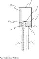
- Figure 1 shows an ignition device known from the prior art for a pyrotechnic protection device, here an airbag igniter as an example. It shows Figure 1 in particular, a sectional view of a metal fixing material feedthrough.
- the metal fixation material feedthrough comprises a metal support part with a base body (1), which here has a disk-shaped basic shape. Basic shapes with a clearance area are also known and encompassed by the invention.
- the metal fixing material leadthrough according to the invention is often also referred to as a base element or base or header for short.
- a metal pin (5) is also arranged as a functional element in a through opening (4) of the base body (1). The through opening (4) was punched out of the base body (1).
- the metal pin (5) is used to contact an ignition bridge (9) with electrical current, via which the propellant charge (25) enclosed in the finished igniter is ignited.
- the ignition bridge rests on the top (11) of the base body.
- the side facing the propellant charge is referred to as the upper side.
- the ignition device is closed by the cap (2) which, together with the base body (1), creates a cavity Forms recording of the propellant charge (25).
- the cap (2) is usually welded to the base body.
- the current feedthrough in the passage opening (4) is designed in the prior art in particular as a glass-metal feedthrough, with glass serving as a fixing material (10) between the metal pin (5) and the wall of the passage opening (4) in the metallic base body (3). It is also possible to use high-performance polymers or other suitable materials in the passage opening, as well as glass ceramic materials.
- the through opening (4) is in the Figure 1
- the example shown is arranged eccentrically with respect to the axial center axis of the base body (1). This ensures that there is sufficient space available for attaching a second metal pin (6) even with a small radius of the base body (3).
- the second metal pin (6) is butt-soldered to the base body (1) by means of a soldered connection and thus serves as a ground pin, also called a ground pin (6).
- metallic solder materials in particular hard solder, are used as the solder material (7).
- the solder material (7) forms a meniscus between the surface of the base body and the ground pin (6).
- FIG. 2 shows, on the other hand, the section through a metal fixing material leadthrough according to the invention parallel to its axial center axis and through it.
- the base body (1) has a first surface (11), here the upper side, and a second surface (12) which in many embodiments runs parallel thereto, here the lower side.
- the upper side (11) usually faces the propellant (25), while the electrical contacts are usually made on the lower side (12).
- the metallic base body (1) has a through opening (4) through which the metal pin (5) is guided as a pin.
- the through opening (4) can be punched out of the base body (1).
- the outer contour of the base body (1) was also punched out of a sheet metal strip in this example, so that the entire base body (1) here is a punched part represents.
- the base body is produced from a wire material by cold forming.
- the metal pin (5) is melted, ie fixed, by means of a glassy or glass-ceramic fixing material (10), electrically insulated from the base body (1) as the first pin, also called the contact pin.
- the first metal pin (5) is in particular hermetically sealed in the first through opening (4) of the metallic base body (1).
- the glassy or glass-ceramic fixing material (10) of this metal fixing material feedthrough is completely surrounded by the material of the base body (1), which represents the outer conductor.
- the vitreous or glass-ceramic fixing material (10) in particular has a lower coefficient of thermal expansion than the metal of the base body (1), so that the base body (1), when it cools down after the metal pin (5) has been glazed into the fixing material (10), so to speak and thus the glass-metal bushing is shrunk on and in this way permanently exerts mechanical pressure on it and the fixing material (10). In this way, a particularly tight and mechanically stable connection between metal pin (5), fixing material (10) and base body (1) is created.
- This arrangement is called pressure glazing and is preferable for airbag igniters, for example.
- the use of glass materials and / or glass ceramic materials is also possible and encompassed by the invention.
- the surface (110) of the fixing material (10) on the top (11) of the base body (1) is a melted-free surface and lies in a plane with the end face (50) of the melted metal pin (5) and advantageously also in a plane with the Upper side (11) of the base body.
- the melted-free surface is advantageously characterized by a glass skin (40) which is reduced compared to the volume of the fixing material (10) Has a proportion of bubbles, in particular no open bubbles on its surface (110), at least in the area of the ignition conductor.
- the ignition conductor (9) rests on the surface (110) of the fixing material and is welded to both the metal pin (5) and the base body (1), ie to the end face (50) of the metal pin (5) and the surface (110) of the base body (1).
- the trench (55) is not shown.
- the second metal pin (6) is connected to the base body (1) as a ground pin by means of solder material (7).
- Figure 3 shows an excerpt from Figure 2 who is in Figure 2 is shown as a broken rectangle. This corresponds to an enlargement in the area of the base body (1), fixing material (10) and the end face (50) of the metal pin (5). For the sake of simplicity, the ignition wire (9) is not shown.
- the trench which is located between the base body (1) and the fixing material (10).
- the trench has the width B and the depth T.
- the trench (55) can in particular be designed as a meniscus-shaped molding of the fixing material (10) onto the base body (1).
- the width B of the trench is at most 0.13 mm, in particular from 0.005 mm to 0.13 mm or from 0.01 to 0.13 mm, and a depth T of at most 0.03 mm, in particular at most 0.015 mm, in particular, the depth T is between 0.025 mm and 0.05 mm.
- the radius of the transition of the surface (11) of the base body to the inner wall (100) of the through opening can be greater than the radius of the transition of the outer wall of the fused metal pin (5) and its end face (50).
- this radius is not in Figure 3 shown.
- this ratio in particular contributes to the fact that the ditch (55) is present at the transition to the base body (1), but not at the transition to the metal pin (5).
- the glass skin (40) which has a significantly lower proportion of bubbles than the volume of the fixing material (10).
- a glass skin (40) on the top (11) of the metal fixing material feedthrough is also possible and encompassed by the invention that a glass skin is also present on the underside (12). This is particularly the case when the fixing material (10) is also melted free on the underside (12).
- the glass skin is visible with optical methods, especially with a microscope, although its thickness can be in the atomic layer range.
- the inner wall (100) of the through opening (4) is in direct contact with the fixing material (10), the fixing material (10) is glazed onto the inner wall (100). It is also possible for a glass skin with a reduced proportion of bubbles to be present between the inner wall (100) of the through opening and the fixing material (10). The same applies to the interface between the fixing material (10) and the outer wall of the metal pin (5).
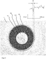
- Figure 4 shows the photograph of the top view of a metal fixing material bushing according to the invention and the measurement curve for the measurement of the trench.
- the through opening is circular and filled with the fixing material (10).
- the metal pin (5) is glazed in; its end face (50) is visible.
- the inner wall (110) of the through opening is again particularly emphasized by the broken line. As described, it is an unsanded surface, the surface of the fixing material has melted free. No exposed bubbles can be seen.
- the glass skin is smooth or dense, so to speak.
- the measurement of the trench (55) with regard to its depth T and width B is also shown.
- the measurement was carried out with a digital measuring microscope.
- the metal fixing material feedthroughs have been ground on their upper side, particularly in industrial mass production for airbag igniters and / or belt tensioners, with both the metal and the fixing material surface being ground. This is usually followed by a cleaning step.
- the metal fixing material feedthroughs according to the invention have the advantage that their fixing material surface is melted free. As a result, the metal surface is not sanded and processing steps can be saved.
- the vitreous or glass-ceramic fixing material according to the invention has the property of forming an at least largely bubble-free surface when it is melted free, so that the risk of exposed bubbles is significantly reduced. Exposed bubbles should be avoided, as they are undesirable when attaching an ignition wire.
Landscapes
- Engineering & Computer Science (AREA)
- Chemical & Material Sciences (AREA)
- General Engineering & Computer Science (AREA)
- Mechanical Engineering (AREA)
- General Chemical & Material Sciences (AREA)
- Organic Chemistry (AREA)
- Life Sciences & Earth Sciences (AREA)
- Chemical Kinetics & Catalysis (AREA)
- Ceramic Engineering (AREA)
- Geochemistry & Mineralogy (AREA)
- Materials Engineering (AREA)
- Combustion & Propulsion (AREA)
- Manufacturing & Machinery (AREA)
- Physics & Mathematics (AREA)
- Fluid Mechanics (AREA)
- Architecture (AREA)
- Civil Engineering (AREA)
- Structural Engineering (AREA)
- Air Bags (AREA)
Abstract
Description
- Die Erfindung betrifft Metall-Fixiermaterial-Durchführung für Durchführungselemente im Allgemeinen, beispielsweise für Durchführungen für Sensoren und/oder Großdurchführungen und/oder Durchführungen in Transistor-Outline-Gehäusen und/oder Batterie- oder Kondensatordurchführungen, sowie solche Durchführungen selbst. Insbesondere vorgesehen sind Durchführungen für Zündvorrichtungen, wie sie zum Zünden einer pyrotechnischen Personenschutzvorrichtung verwendet werden, insbesondere aber solche, die für Airbagzünder und/oder Gurtstraffer und/oder Gasgeneratoren einsetzbar sind. Insbesondere betrifft die Erfindung die Ausgestaltung des Sockels solcher Durchführungselemente, das Verfahren zu dessen Herstellung und dessen Anwendungen.
- Durchführungen von Sensoren können insbesondere Sensorelemente mit Strom versorgen und/oder deren Signale an Auswerteeinheiten weiterleiten. Großdurchführungen werden im Allgemeinen in Sicherheitsbehältern eingesetzt, zum Beispiel in Flüssiggastanks und/oder Reaktoren.
- Als Batterie- oder Kondensatordurchführungen werden in der Regel Durchführungen durch die Gehäuse von Batterien einschließlich Akkumulatoren oder von Kondensatoren verstanden. Der Begriff umfasst ebenfalls das Gebiet der Superkondensatoren, auch Supercaps genannt. Die Durchführung dient üblicherweise dazu, Elektroden im Innern des Batterie- oder Kondensatorgehäuses zu kontaktieren.
- Ein Transistor-Outline-Gehäuse, auch TO-Gehäuse genannt, ist ein stromführendes Elektronikgehäuse. Ein TO-Gehäuse besteht grundsätzlich aus zwei Bauteilen, einem Sockel und einer Kappe. Während die Sockel vor allem die Stromversorgung der gekapselten Bauteile sicherstellt, dient die Kappe im Bereich der Opto-Elektronik der sicheren Übertragung optischer Signale. Dies umfasst sowohl die Sender (z.B. Laserdioden), als auch die Empfänger von optischen Signalen (z.B. Fotodioden). Der TO-Sockel stellt die mechanische Basis für die Montage von elektronischen und optischen Bauteilen dar, wie z.B. Halbleiter, Laserdioden oder auch einem einfachen elektrischen Schaltkreis. Gleichzeitig versorgt er die geschützten Komponenten mit Hilfe von Anschlussstiften mit Strom.
- Als pyrotechnische Personenschutzvorrichtungen kommen in Kraftfahrzeugen insbesondere Airbags und/oder Gurtstraffer zum Einsatz. Derartige Sicherheitssysteme können das Verletzungsrisiko erheblich senken. Voraussetzung ist jedoch, dass im Falle eines Zusammenstoßes die jeweiligen Sicherheitssysteme nicht versagen. Besonderes Augenmerk wird dabei insbesondere auch auf die Zünder solcher pyrotechnischen Einrichtungen gerichtet, welche für die Funktion einer solchen Sicherheitseinrichtung unerlässlich sind. Insbesondere müssen die Zünder auch viele Jahre nach ihrer Herstellung noch einwandfrei funktionieren. Als mittlere Lebensdauer solcher Zünder wird oftmals 15 Jahre angegeben. Um eine dauerhaft einwandfreie Funktion zu gewährleisten, muss dabei sichergestellt sein, dass sich die im Zünder vorhandene Treibladung im Laufe der Zeit nicht verändert. Derartige Veränderungen können beispielsweise durch in den Zünder eindringende Feuchtigkeit verursacht werden. Es ist daher wichtig, die Treibladung des Zünders hermetisch zu verkapseln. Auch muss der Zünder die Gase der gezündeten Treibladung in die richtige Richtung freisetzen, um die Treibladung eines Gasgenerators des Sicherheitssystems zu zünden.
- Um dies zu gewährleisten, weisen aus dem Stand der Technik bekannte Zünder eine Kappe oder einen Deckel und einen vergleichsweise massiven Sockel auf, zwischen denen die Treibladung in einem aus diesen Teilen gebildeten Hohlraum eingeschlossen ist. Durch den Sockel wird mittels elektrischer Anschlüsse der Strom zum Zünden der Treibladung geleitet. Daher weist der Sockel in der Regel Durchgangsöffnungen auf, in denen sich Metallstifte befinden, die auf der einen Seite mittels einer Steckverbindung mit elektrischem Strom versorgt werden können und auf der anderen Seite beispielsweise mittels einer Zündbrücke verbunden sind, die beim Stromdurchfluss in Kontakt mit dem Treibmittel die Zündung desselben bewirkt. Der Sockel wird daher auch allgemein Durchführungselement genannt. Bei der Auslegung des Durchführungselements muss sichergestellt werden, dass bei der Zündung der Treibladung auf jeden Fall die Kappe oder der Deckel oder ein Teil davon abreißt und nicht die elektrischen Durchführungen aus dem Sockel getrieben werden.
- Bei solchen Durchführungselementen besteht der Grundkörper des Sockels aus Metall und die Zündbrücke wird mittels eines angeschweißten Brückendrahtes realisiert. Bei dieser Ausführungsform ist ein Metallstift als Pin in einem elektrisch isolierenden Fixiermaterial in einer Durchgangsöffnung des Grundkörpers fixiert. Als Fixiermaterial wird üblicherweise ein Glasmaterial, insbesondere ein Glaslot verwendet. Dadurch ist dieser Metallstift zum Außenleiter durch Glas isoliert. Ebenso möglich sind Keramik-, Glaskeramik- und/oder Polymer als Isolationsmaterial.
- Ein zweiter Metallstift als Pin ist mit dem Außenleiter, der durch den Grundkörper oder auch Bodenplatte genannt, repräsentiert wird, verschweißt oder verlötet. Auf der Oberseite des Durchführungselements - das ist die Seite, die der Zündkappe der endmontierten Zündvorrichtung zugewandt ist - kommt somit ein Brückendraht (meist aus einer Wolframlegierung) als Zündbrücke in Kontakt mit der Oberfläche des Glasmaterials. Damit der Brückendraht nicht beschädigt wird und das Zündelement im Gebrauch beispielsweise in einem Kraftfahrzeug eine lange Lebensdauer aufweist, muss die Oberfläche des Glasmaterials üblicherweise geschliffen werden, da Rauigkeiten der Oberfläche den Brückendraht beschädigen können.
- Zündvorrichtungen der vorgenannten Art sind beispielsweise aus der
EP 1813906 B1 bekannt. - Die
EP 0586133 A2 beschreibt die Herstellung von Metall-Fixiermaterial-Durchführungen für Airbagzünder, bei welcher der Kontaktpin in ein Glasmaterial in der Durchgangsöffnung eingeglast ist und die Oberfläche des Grundkörpers und des Fixiermaterials vor dem Anbringen des Brückendrahts geschliffen wird. - TO-Gehäuse sind beispielsweise in der
US 8,908,728 B1 dargestellt. Hier ist es denkbar, einen Massestift mit dem Grundkörper zu verbinden, um den Grundkörper elektrisch zu erden. - Vor diesem Hintergrund ist es die Aufgabe der vorliegenden Erfindung, eine Metall-Fixiermaterial-Durchführung für ein Durchführungselement, insbesondere für Anzünder von Airbags und/oder Gurtstraffern, zur Verfügung zu stellen, bei dem die Nachteile des Standes der Technik vermieden werden und ein Schleifen der Oberfläche vermieden wird, sowie ein Verfahren zur Herstellung.
- Die Aufgabe wird gelöst durch die Metall-Fixiermaterial-Durchführung und das Verfahren zu deren Herstellung gemäß den unabhängigen Ansprüchen. Bevorzugte Ausführungsformen und Anwendungen ergeben sich aus den davon abhängigen Ansprüchen.
- Die erfindungsgemäße Metall-Fixiermaterial-Durchführung umfasst einen insbesondere metallischen Grundkörper sowie zumindest eine Durchgangsöffnung, in welcher zumindest ein Metallstift in einem elektrisch isolierenden glasigen oder glaskeramischen Fixiermaterial eingeschmolzen und auf diese Weise in diesem fixiert ist. Die Oberfläche des glasigen oder glaskeramischen Fixiermaterials ist eine freigeschmolzene Oberfläche, die besonders vorteilhaft frei von offenliegenden Blasen ist. Freigeschmolzen im Sinne der Erfindung heißt, dass sich die Oberfläche beim Erkalten des aufgeschmolzenen Glasmaterials von selbst ausbildet. Sie ähnelt visuell feuerpolierten Oberflächen und ist als Solches mit bloßem Auge erkennbar, insbesondere da sie einen spiegelnden Glanz aufweisen kann.
- Die Oberfläche des freigeschmolzenen Fixiermaterials liegt auf einer Ebene mit der Stirnfläche des zumindest einen Metallstifts, der in dem Fixiermaterial eingeschmolzen ist. Damit ist selbstverständlich diejenige Stirnfläche des Metallstifts gemeint, welche dem Fixiermaterial am nächsten liegt und welche zum Verbinden mit dem Leiter oder Zündleiter vorgesehen ist, mithin der Oberseite der Metall-Fixiermaterial-Durchführung.
- Bei der Herstellung der Metall-Fixiermaterial-Durchführung wird üblicherweise von einem Pressling ausgegangen, der zusammen mit dem Metallstift in der Durchgangsöffnung angeordnet und dann erhitzt wird, so dass der Pressling aufschmilzt und sich mit dem Grundkörper und dem Metallstift verbindet. Der Pressling wir üblicherweise hergestellt, indem das Glas- oder glaskeramische Material zermahlen, mit meistens organischen Bindern versetzt und in Form gepresst wird. Es ist ebenso möglich, dass der Pressling ebenfalls gesintert wird, bevor das Einschmelzen des Metallstifts erfolgt. Ebenso ist es möglich, dass das glaskeramische Material während des Erhitzens und/oder Abkühlens aus dem zuvor amorphen glasigen Material entsteht.
- Beim Einschmelzen des Metallstifts und dem Verbinden mit dem Grundkörper brennt der Binder aus. Das glasige oder glaskeramische Fixiermaterial in der Durchgangsöffnung ist üblicherweise mit Blasen versetzt und weist Überstände über die Oberfläche des Grundkörpers auf. Ebenso wird der Metallstift üblicherweise so angeordnet, dass er über die Oberfläche des Grundkörpers hervorsteht. Um eine plane Oberfläche zu erzielen, die auf einer Ebene liegt, wird daher davon ausgegangen, dass die Oberfläche plan geschliffen werden muss.
- Im Gegensatz dazu wird entsprechend der vorliegenden Erfindung die Oberfläche des Fixiermaterials während des Aufschmelzvorgangs freigeschmolzen. Dabei wird insbesondere der zumindest eine Metallstift auch so in der Durchgangsöffnung angeordnet, dass seine Stirnfläche in einer Ebene mit der Oberfläche des Grundkörpers liegt. Die Erfinder haben festgestellt, dass durch das freischmelzen eine glatte Oberfläche des glasigen oder glaskeramischen Fixiermaterials resultiert und das Schleifen unnötig ist.
- Die Erfindung sieht ebenso vor, dass zwischen dem Grundkörper und dem zumindest einen Metallstift ein elektrischer Leiter, insbesondere Zündleiter angebracht ist, der den Grundkörper und den zumindest einen Metallstift elektrisch leitfähig verbindet. Die die Oberfläche des Fixiermaterials ist zumindest im Bereich des Leiters frei von offenliegenden Blasen.
- Besonders vorteilhaft ist die gesamte Oberfläche des Fixiermaterials frei von offenliegenden Blasen. Allerdings ist es auch technisch ausreichend und von der Erfindung, wenn die gesamte Oberfläche des Fixiermaterials im Wesentlichen frei von aufgeschmolzenen Blasen ist, wobei darunter eine Anzahl von höchstens 5 offenen Blasen auf der Oberfläche verstanden wird. Diese können auf der Oberfläche verteilt sein, wie beschrieben nicht jedoch in dem Bereich, auf dem der Zünddraht vorhanden ist, d.h. insbesondere auf dem Fixiermaterial aufliegt.
- Gängigerweise wird für den Grundkörper Normalstahl wie St 35 und/oder St 37 und/oder St 38 oder Edelstahl und/oder nichtrostender Stahl als Material für in Grundkörper eingesetzt. Edelstahl nach DIN EN 10020 ist eine Bezeichnung für legierte oder unlegierte Stähle, deren Schwefel- und Phosphorgehalt (sog. Eisenbegleiter) 0,035 % nicht übersteigt. Häufig sind danach weitere Wärmebehandlungen (z. B. Vergüten) vorgesehen. Zu den Edelstählen zählen zum Beispiel hochreine Stähle, bei denen durch einen besonderen Herstellungsprozess Bestandteile wie Aluminium und Silizium aus der Schmelze ausgeschieden werden, ferner auch hochlegierte Werkzeugstähle, die für eine spätere Wärmebehandlung vorgesehen sind. Solche enthalten insbesondere Chrom. Verwendbar sind beispielsweise: X12CrMoS17, X5CrNi1810, XCrNiS189, X2CrNi1911, X12CrNi177, X5CrNiMo17-12-2, X6CrNiMoTi17-12-2, X6CrNiTi1810 und X15CrNiSi25-20, X10CrNi1808, X2CrNiMo17-12-2, X6CrNiMoTi17-12-2.
- Um eine maximale Herstellungseffizienz der erfindungsgemäßen Durchführung zu gewährleisten, kann der metallische Grundkörper vorteilhaft aber auch aus keinem Edelstahl bestehen. Vorteilhaft wird der Grundkörper stattdessen aus einem Stahl aus der Gruppe 1.01xx bis 1.07xx (unlegierte Qualitätsstähle) gebildet. Die Angabe der Stahlgruppe erfolgt dabei nach DIN EN 10 027-2, wobei die erste Ziffer die Werkstoff-Hauptgruppe und die Ziffernfolge nach dem ersten Punkt die Stahlgruppen-Nummer angibt.
- Um eine möglichst gute Korrosionsbeständigkeit zu gewährleisten, kann der Grundkörper mit Metallen beschichtet sein. Bevorzugt wird eine Nickelbeschichtung verwendet. Dies trifft insbesondere für Grundkörper zu, die aus unlegierten Qualitätsstählen gebildet werden.
- Das glasige oder glaskeramische Fixiermaterial wird vorteilhaft so gewählt, dass dessen thermische Ausdehnung niedriger ist als diejenige des metallischen Grundkörpers. Beim Aufschmelzen und anschließendem Abkühlen schrumpft der Grundkörper sozusagen auf das erstarrte Fixiermaterial, so dass eine sogenannte Druckdurchführung, auch Druckeinglasung genannt, erhalten wird. Dies bedeutet, dass der Grundkörper einen axialen Druck auf das Fixiermaterial ausübt, was dessen mechanische Haltekraft in der Durchgangsöffnung erhöht.
- Auf diese Weise wird eine hermetisch dichte Metall-Fixiermaterial-Durchführung erreicht.
- Die Erfinder haben festgestellt, dass beim vorbeschriebenen Vorgehen, insbesondere beim Freischmelzen der Oberfläche, das glasige oder glaskeramischen Fixiermaterial zwar in seinem Volumen Blasen mit einem Blasenanteil BV aufweisen kann, an seiner Oberfläche aber eine Glashaut, welche einen Blasenanteil aufweist, der erheblich kleiner als BV ist. Besonders bevorzugt ist die Glashaut im Wesentlichen blasenfrei, was heißt dass höchstens 5 Blasen vorliegen, oder sogar vollständig blasenfrei. Insbesondere ist die Glashaut und/oder die Oberfläche des Fixiermaterials in dem Bereich, auf dem der Zünddraht aufliegt, blasenfrei.
- Dadurch, dass das Fixiermaterial eine freigeschmolzene Oberfläche hat, ist ihre Rauigkeit geringer als bei den bisher geschliffenen Metall-Fixiermaterial-Durchführungen. Insbesondere beträgt der Mittenrauwert Ra der Oberfläche des glasigen oder glaskeramischen Fixiermaterials weniger als 0,1 µm insbesondere im Bereich von 0,02 µm bis 0,05 µm liegt. Im Gegensatz dazu betragen übliche Ra Werte bei den bisherigen geschliffenen Metall-Fixiermaterial-Durchführungen zwischen 0,2 µm und 0,5 µm. Die höheren Rauhigkeitswerte des bisheriges geschliffenen Fixiermaterials resultieren i.d.R. aus den verbliebenen Schleifspuren, insbesondere in Form von Riefen.
- Der Mittenrauwert Ra ist gemäß DIN EN ISO 4287:2010 definiert und wird wie dem Fachmann bekannt bestimmt. Die mittlere Rauheit oder auch Mittenrauwert Ra gibt den mittleren Abstand eines Messpunktes innerhalb eines vertikalen Schnitts, d.h. des Profils der Mikrostrukturierung zur Mittellinie an. Die Mittellinie schneidet innerhalb der Bezugsstrecke das wirkliche Profil so, dass die Summe der Profilabweichungen (bezogen auf die Mittellinie) minimal wird. Die mittlere Rauheit Ra entspricht also dem arithmetischen Mittel der betragsmäßigen Abweichung von der Mittellinie.
- Die glattere Oberfläche der erfindungsgemäßen Metall-Fixiermaterial-Durchführung hat gegenüber dem Stand der Technik weiterhin den Vorteil, dass die Gefahr von Beschädigungen des Brückendrahtes verringert wird, wenn dieser auf dem Fixiermaterial aufliegt. In Airbagzündern oder Gurtstraffern ist der Brückendraht in Berührung mit dem Zündmaterial, das häufig in Pulverform vorliegen kann. Auch wenn die Korngröße des Pulvers üblicherweise größer als die Riefen der Schleifspuren sind, kann im Laufe der Produktlebenszeit Pulverabrieb und damit sehr feines Korn entstehen, welches sich in die Riefen unter den Brückendraht klemmen und so mechanischen Stress auf diesen ausüben kann. Durch die erfindungsgemäße Metall-Fixiermaterial-Durchführung wird dies vermieden.
- In einer weiteren bevorzugten Ausführungsform ist der Grundkörper so ausgebildet, dass ein kontinuierlicher Übergang von der Oberfläche des Grundkörpers zur inneren Wandung der Durchgangsöffnung vorhanden ist, insbesondere mit zunehmendem Gefälle in Richtung zur inneren Wandung der Durchgangsöffnung. Kontinuierlicher Übergang bedeutet, dass wenn der Schnitt durch diesen Bereich als Kurve aufgefasst wird, die erste Ableitung dieser Kurve einen stetigen Verlauf hat. Im Unterschied dazu haben die Grundkörper aus dem Stand der Technik einen scharfen Knick, so dass die erste Ableitung deren Schnitts unstetig ist. Diese Ausführung hat den Vorteil, dass der Grundkörper einfach über Umformungs- und/oder Stanzverfahren hergestellt werden kann, insbesondere die Durchgangsöffnung, ohne in weitere Nachverarbeitungsschritte zum Erzielen senkrechter Winkel einsetzen zu müssen. Ein weiterer Vorteil dieser Grundkörpergestaltung ist, dass das Volumen des Presslings, das für den Füllstand des Fixiermaterials in der Durchgangsöffnung verantwortlich ist, unkritischer bzgl. Volumenschwankungen ist. Das bedeutet, bei gegebener Volumenschwankung ändert sich der Füllstand in der Durchgangsöffnung weniger als der Durchmesser des Fixiermaterials, was für das Anbringen des Brückendrahts weniger kritisch ist als eine eventuelle Stufe, wie sie bei nicht ausreichender Füllung resultieren würde.
- Der kontinuierliche Übergang hat weiterhin den Effekt, dass sich eine dünne Fixiermaterialschicht auf dem flach zur Durchgangsöffnung hin abfallenden Bereich befindet. Überraschend hat sich gezeigt, dass obwohl es sich um eine Druckeinglasung handelt, keine Abplatzungen des Fixiermaterials zu beobachten sind.
- Besonders bevorzugt ist vorgesehen, dass sich zwischen der inneren Wandung der Durchgangsöffnung und dem glasigen oder glaskeramischen Fixiermaterial im Bereich von dessen Oberfläche ein Graben befindet. Ein Graben repräsentiert im Allgemeinen eine Vertiefung in der Oberfläche des Fixiermaterials. Die Breite B des Grabens beträgt bevorzugt höchstens 0,13 mm, besonders bevorzugt von 0,005 mm bis 0,13 mm oder 0,01 bis 0,13 mm. Insbesondere bevorzugt beträgt die Tiefe T dieses Grabens höchstens 0,03 mm, insbesondere höchstens 0,015 mm, insbesondere bevorzugt beträgt die Tiefe T zwischen 0,05 mm und 0,025 mm.
- Die Bildung des Grabens kann durch die vorgenannte Ausgestaltung des Übergangs der Oberfläche des Grundkörpers zur inneren Wandung der Durchgangsöffnung begünstigt sein, d.h. diese Ausgestaltung und das Vorhandensein des Grabens wirken besonders vorteilhaft zusammen.
- Das Vorhandensein des Grabens hat den Vorteil, dass dadurch, insbesondere im Betrieb der Metall-Fixiermaterial-Durchführung, ein Stopp für Filmbelegung der Oberfläche des Fixiermaterials und/oder der Oberfläche des Grundkörpers erreicht werden kann. Solche Filme können insbesondere wasserhaltige Filme und/oder Belegungen sein, die im Langzeitbetrieb auftreten können und im schlechtesten Fall zu reduzierten Übergangswiderständen, Kurzschlüssen und/oder elektrochemischer Korrosion und damit zu Beschädigungen des Bauteils umfassend die Metall-Fixiermaterial-Durchführung führen können.
- Der Graben kann insbesondere vorteilhaft beim Aufschmelzen des Fixiermaterials und dessen anschließenden Abkühlen von selbst ausgebildet werden. Es wird vermutet, dass dies aus der Anhaftung- und Benetzungseigenschaften des glasigen oder glaskeramischen Fixiermaterials folgt. Ebenso ist es möglich, den Graben einzuprägen, solange das erwärmte Fixiermaterial noch formbar ist.
- Vorteilhaft ist die Ausführungsform, in der das glasige oder glaskeramische Fixiermaterial ohne Grabenbildung auf der Oberfläche des zumindest einen Metallstifts an- und/oder aufliegt. Dies bedeutet, der vorgenannte Graben befindet sich nur an dem Übergangsbereich von Fixiermaterial zu Grundkörper und nicht an dem Übergangsbereich von Fixiermaterial zu Metallstift. Dies kann insbesondere dadurch erreicht werden, wenn der Radius der ggfls. vorhandenen Abrundung am Metallstift, d.h. beim Überhang von dessen Stirn- zur Mantelfläche, kleiner ist als der Radius des Übergangs des Grundkörpers von dessen Oberfläche zur inneren Wandung der Durchgangsöffnung.
- Wie bereits beschrieben kann der Graben dabei vorteilhaft als Stopp für störende, die Oberfläche belegende Filme dienen, welche einen Einfluss auf das elektrische Verhalten des elektrischen Leiters haben können, insbesondere das Zündverhalten. Andererseits ist der Graben vorteilhaft so dimensioniert, dass sich keine störenden großen Partikel zwischen sie und den elektrischen Leiter klemmen und so den Leiter mechanisch über Gebühr belasten könnten.
- Insbesondere wird der Metallstift so angeordnet, dass die Oberseite, d.h. die ebene Stirnfläche des Metallstifts, in einer Ebene mit der Oberfläche des glasigen oder glaskeramischen Fixiermaterials liegt. Vorteilhaft ist der Metallstift verrundet, d.h. insbesondere ist der Übergang zwischen der Oberseite des Metallstifts und dessen Seitenwand abgerundet, wobei der Übergangspunt zwischen dieser Abrundung und der Seitenwand unterhalb der Oberfläche des glasigen oder glaskeramischen Fixiermaterials liegt.
- Insbesondere ist der Graben umlaufend, v.a. kreisrund. Bevorzugt ist die Durchgangsöffnung in der Aufsicht kreisrund ausgebildet ist und der Graben folgt kreisrund der inneren Wandung der Durchgangsöffnung, ggfls. mit einem Abstand.
- Besonders bevorzugt ist eine Metall-Fixiermaterial-Durchführung, bei der zwischen dem Grundkörper und dem zumindest einen Metallstift ein elektrischer Leiter, insbesondere ein drahtförmiger Leiter, insbesondere ein Zündleiter angebracht ist, der den Grundkörper und den dem zumindest einen Metallstift elektrisch leitfähig verbindet. Der Leiter liegt zumindest bereichsweise auf der Oberfläche des glasigen oder glaskeramischen Fixiermaterials auf und überbrückt bevorzugt den Graben. In diesem Bereich, in dem der Graben überbrückt wird, befindet sich unter dem Leiter ein Freiraum. Ebenso ist es möglich, diesen Freiraum aufzufüllen und/oder zu beschichten, z.B. mit einem Kunststoff, insbes. einem hydrophoben Kunststoff oder einem solchen mit einer hydrophoben Oberfläche. Wie beschrieben kann der Graben als Abrisskante für insbesondere elektrisch leitende Belegungen oder korrosive Filme dienen. Die umlaufende Kante schirmt das Fixiermaterial und/oder den zumindest einen Metallstift sozusagen von diesen Belegungen und/oder Filmen ab.
- In einer weiteren bevorzugten Ausführungsform besteht der Grundkörper zumindest an der Grenzfläche zu dem glasigen oder glaskeramischen Fixiermaterial aus einem Stahl, insbesondere rostfreien Edelstahl. Ebenso bevorzugt besteht der zumindest eine Metallstift zumindest an der Grenzfläche zu dem glasigen oder glaskeramischen Fixiermaterial aus einem Stahl, insbesondere rostfreien Edelstahl. Besonders vorteilhaft weist der Stahl und/oder Edelstahl eine Benetzung und/oder Anhaftung gegenüber Glas auf, welche die Ausbildung des Grabens zumindest unterstützt.
- Vorteilhaft und von der Erfindung umfasst ist es, wenn die Oberseite des Metallstifts in einer Ebene mit der Oberfläche des glasigen oder glaskeramischen Fixiermaterials liegt. Insbesondere kann der Übergang zwischen der Oberseite des Metallstifts und dessen Seitenwand abgerundet sein, wobei der Übergangspunkt zwischen dieser Abrundung und der Seitenwand unterhalb der Oberfläche des glasigen oder glaskeramischen Fixiermaterials liegt. Die Abrundung wird also sozusagen in das Fixiermaterial hineingezogen. Gegenüber einem scharfen Übergang, bei dem die Seitenwand des Metallstifts direkt senkrecht auf dessen Oberfläche trifft, hat dies den Vorteil, dass die Wahrscheinlichkeit zur Rissbildung an der Grenzfläche zwischen Metallstift und Fixiermaterial reduziert ist.
- Wie beschrieben liegt die Oberseite des Metallstifts, d.h. dessen Stirnfläche, in einer Ebene mit der Oberfläche des glasigen oder glaskeramischen Fixiermaterials liegt. Insbesondere kann der Übergang zwischen der Oberseite des Metallstifts und dessen Seitenwand abgerundet sein, wobei der Übergangspunt zwischen dieser Abrundung und der Seitenwand unterhalb der Oberfläche des glasigen oder glaskeramischen Fixiermaterials liegt. Die Abrundung wird also sozusagen in das Fixiermaterial hineingezogen. Gegenüber einem scharfen Übergang, bei dem die Seitenwand des Metallstifts direkt senkrecht auf dessen Oberfläche trifft, hat dies den Vorteil, dass die Wahrscheinlichkeit zur Rissbildung an der Grenzfläche zwischen Metallstift und Fixiermaterial reduziert ist.
- Ebenso vorgesehen ist, dass zwischen dem Grundkörper und dem zumindest einen Metallstift ein elektrischer Leiter, insbesondere Zündleiter angebracht ist, der den Grundkörper und den zumindest einen Metallstift elektrisch leitfähig verbindet. Üblicherweise wird dieser angeschweißt. Dieser Leiter liegt zumindest bereichsweise auf der Oberfläche des glasigen oder glaskeramischen Fixiermaterial auf. Insbesondere überbrückt er den beschriebenen Graben.
- Die Erfindung umfasst ebenso das Verfahren zur Herstellung einer Metall-Fixiermaterial-Durchführung insbesondere für Anzünder von Airbags und/oder Gurtstraffern, mit zumindest einem Metallstift, der in eine Durchgangsöffnung eines Grundköpers in einem glasigen oder glaskeramischen Fixiermaterial durch Erwärmen und anschließendem Abkühlen eingeschmolzen ist, welches eine Oberfläche zwischen dem zumindest einen Metallstift und dem Grundkörper aufweist, wobei beim Einschmelzen des zumindest einen Metallstifts in das glasige oder glaskeramische Fixiermaterial das erwärmte Fixiermaterial an dieser Oberfläche freigeschmolzen wird.
- Bei diesem Vorgang glast das Fixiermaterial an der inneren Wandung der Durchgangsöffnung und der äußeren Wand des zumindest einen Metallstifts an,
- Alle zuvor bzgl. der Metall-Fixiermaterial-Durchführung beschriebenen Merkmale sind auch auf das Verfahren übertragbar.
- Das beanspruchte Verfahren umfasst einen Teil der gesamten Herstellungsschritte einer Durchführung und/oder eines Airbagzünders oder Gurtstraffers.
- Bevorzugt bildet sich beim Freischmelzen eine im wesentlichen blasenfrei Oberfläche des Fixiermaterials insbesondere von selbst aus. Im wesentlichen balsenfrei bedeutet höchstens 5 Blasen an der Oberfläche, wovon natürlich auch eine vollständige Blasenfreiheit umfasst ist. Bevorzugt beträgt der Mittenrauwert Ra der Oberfläche des glasigen oder glaskeramischen Fixiermaterials weniger als 0,1 µm, insbesondere liegt Ra im Bereich von 0,015 µm bis 0,055 µm, besonders vorteilhaft von 0,02 µm bis 0,05 µm. In einer bevorzugten Ausführungsform liegt das glasige oder glaskeramische Fixiermaterial ohne Grabenbildung an der Oberfläche des zumindest einen Metallstifts an. Dies bedeutet, dass es besonders vorteilhaft ist, dass der Graben zwischen Grundkörper und Fixiermaterial vorhanden ist, nicht aber zwischen Fixiermaterial und Metallstift.
- Die Durchgangsöffnung selbst ist bevorzugt in der Aufsicht kreisrund ausgebildet und der Graben folgt besonders bevorzugt kreisrund der inneren Wandung der Durchgangsöffnung. Eine kreisrunde Durchgangsöffnung kann insbesondere durch Stanzen und/oder Umformen erhalten werden. Bohren und andere geeignete Verfahren sind allerdings ebenso möglich.
- Wie bereits beschrieben ist es ein besonders vorteilhaftes Verfahren, den Grundkörper und/oder die Durchgangsöffnung durch Umformen und/oder Stanzen zu erzeugen. Insbesondere materialeffizient kann der Grundkörper durch Umformen hergestellt werden, wobei die zumindest eine Durchgangsöffnung ausgestanzt wird.
- Besonders vorteilhaft ist es, wenn der Grundkörper so geformt ist oder wird, dass ein kontinuierlicher Übergang von der Oberfläche des Grundkörpers zur inneren Wandung der Durchgangsöffnung vorhanden ist, insbesondere mit zunehmendem Gefälle in Richtung zur inneren Wandung der Durchgangsöffnung. Dies entspricht sozusagen einer Abrundung mit progressiver Steigung. Diese Form kann insbesondere beim Stanzvorgang der Durchgangsöffnung erzeugt werden.
- In einem bevorzugten Verfahren bildet sich zwischen der inneren Wandung der Durchgangsöffnung und dem glasigen oder glaskeramischen Fixiermaterial im Bereich dessen Oberfläche beim Erwärmen und/oder Abkühlen einen Graben (55) selbständig ausbildet. Alternativ wird diese eingeprägt, beispielsweise mit einem Stempel- oder Prägewerkzeug. Insbesondere weist der Graben eine Breite B auf, die bevorzugt höchstens 0,13 mm beträgt. Besonders bevorzugt beträgt die Tiefe T des Grabens höchstens 0,03 mm, insbesondere höchstens 0,015 mm, insbesondere bevorzugt beträgt die Tiefe T zwischen 0,05 mm und 0,025 mm.
- Ebenso möglich ist es, den Graben mit geeigneten Werkzeugen, beispielsweise Stempeln, einzuprägen oder materialabtragend zu erzeugen.
- In der Weiterverarbeitung kann ein elektrischer Leiter wie beschrieben zwischen Metallstift und der Oberfläche des Grundkörpers angebracht werden, insbesondere angeschweißt werden.
- Ebenso üblich ist es oftmals, dass zumindest ein weiterer Leiter, insbesondere Metallstift, elektrisch leitend mit dem Grundkörper verbunden wird. Dies ist üblicherweise ein Erdungs- oder Masseleiter. Bei der beschriebenen elektrisch leitenden Verbindung eines Metallstifts mit dem Grundkörper handelt es sich üblicherweise um eine Lotverbindung. Ebenso möglich es es, diesen Leiter an den Grundkörper zu schweißen.
- Bevorzugte Anwendungen der erfindungsgemäßen Metall-Fixiermaterial-Durchführung und/oder des erfindungsgemäßen Verfahrensergebnisses ist in Airbagzündern und/oder Gurtstraffern und/oder Gasgeneratoren.
- Bei Airbagzündern und/oder Gurtstraffern und/oder Gasgeneratoren ist das der in der Durchgangsöffnung fixierte Metallstift, ebenso wie der mit dem Grundkörper verlötete Massestift, üblicherweise zumindest in Teilbereichen entlang ihrer Achse mit Gold beschichtet. Die Goldbeschichtung bewirkt eine dauerhafte Unempfindlichkeit gegenüber Korrosion und einen dauerhaften Kontakt. Häufig sind die Metallstifte an ihren Endbereichen mit Gold beschichtet. Auf diese Weise ist bevorzugt der Bereich des Metallstifts vergoldet, der sich bei der Montage zum Gebrauch der Zündvorrichtung innerhalb der Steckverbindung befindet. Auf diese Weise können die Übergangswiderstände im Steckkontakt reduziert werden.
- In einer vorteilhaften Ausführungsform sind zumindest zwei Metallstifte auf der dem Treibmittel zugewandten Seite des Grundkörpers mittels einer Zündbrücke elektrisch leitend miteinander verbunden. Die Zündbrücke kann durch den bereits beschriebenen Zünddraht gebildet werden.
- Wie voranstehend beschrieben kann Rauheit der Fixiermaterialoberfläche, bzw. im Sinne der Erfindung eher Glattheit, durch die mittlere Rauheit Ra charakterisiert werden. Ebenso kann die gemittelte Rautiefe Rz wie dem Fachmann bekannt angegeben werden.
- In Versuchen, die ebenfalls Ausführungsbeispiele repräsentieren, wurde mittels dem beschriebenen Verfahren die beschriebene Metall-Fixiermaterial-Durchführung hergestellt und die Rauigkeit der Fixiermaterialoberfläche bestimmt, welche erfindungsgemäß freigeschmolzen ist. Als Vergleich sind in Tabelle 1 ebenso die Messwerte für entsprechend dem Stand der Technik geschliffene Fixiermaterialoberflächen angegeben. Als Messmethode fand die dem Fachmann bekannte taktile Messung mittels Hommel Taster Anwendung.
Tabelle 1: Rauhigkeitsmessungen an freigeschmolzener Fixiermaterialoberfläche Erfindungsgemäß: Freigeschmolzene Fixiermaterialoberfläche Stand der Technik: Geschliffene Fixiermaterialoberfläche Messung Nr. Ra [µm] Rmax [µm] Rz [µm] Ra [µm] Rmax [µm] Rz [µm] 1 0,032 0,301 0,249 1,206 15,524 9,217 2 0,030 0,293 0,235 0,905 14,364 9,974 3 0,024 0,275 0,192 0,679 11,667 7,082 4 0,023 0,662 0,261 0,954 11,466 9,286 5 0,024 0,178 0,166 1,174 14,079 8,915 6 0,023 0,200 0,168 Mittelwert: 0,026 0,212 0,984 8,895 - Die Erfindung wird im Folgenden anhand der Figuren näher erläutert. Die Zeichnungen sind nicht maßstabsgetreu, die dargestellten Ausführungsformen sind schematisch. Die Figuren stellen auch exemplarisch Ausführungsbeispiele dar. Alle in den Figuren dargestellten Bezugszeichen gelten auch für die jeweils anderen Figuren.
-
Figur 1 zeigt eine bekannte Zündvorrichtung beinhaltend eine Metall-Fixiermaterial-Durchführung gemäß dem Stand der Technik, mit einer geschliffenen Oberfläche, auf welcher der Zünddraht aufliegt. -
Figur 2 zeigt einen Schnitt durch eine erfindungsgemäße Metall-Fixiermaterial-Durchführung parallel zu deren axialen Mittenachse. -
Figur 3 zeigt einen Ausschnitt ausFigur 2 . -
Figur 4 zeigt die Fotografie der Draufsicht auf eine erfindungsgemäße Metall-Fixiermaterial-Durchführung und die Messkurve der Vermessung des Grabens. - In
Figur 1 ist eine aus dem Stand der Technik bekannte Zündvorrichtung für eine pyrotechnische Schutzvorrichtung dargestellt, hier als Beispiel ein Airbagzünder. Dabei zeigtFigur 1 insbesondere eine Schnittansicht einer Metall-Fixiermaterial-Durchführung. Die Metall-Fixiermaterial-Durchführung umfasst ein Metall-Trägerteil mit einem Grundkörper (1), welcher hier eine scheibenförmige Grundform aufweist. Grundformen mit Freistellungsbereich sind ebenso bekannt und von der Erfindung umfasst. Die erfindungsgemäße Metall-Fixiermaterial-Durchführung wird häufig auch als Sockelelement oder kurz Sockel oder englisch Header bezeichnet. In einer Durchgangsöffnung (4) des Grundkörpers (1) ist außerdem ein Metallstift (5) als Funktionselement angeordnet. Die Durchgangsöffnung (4) wurde dabei aus dem Grundkörper (1) ausgestanzt. Der Metallstift (5) dient zur Kontaktierung einer Zündbrücke (9) mit elektrischem Strom, über die die im fertigen Zünder eingeschlossene Treibladung (25) gezündet wird. Die Zündbrücke liegt auf der Oberseite (11) des Grundkörpers auf. Als Oberseite wird die der Treibladung zugewandte Seite bezeichnet. Die Zündvorrichtung wird durch die Kappe (2) verschlossen, welche zusammen mit dem Grundkörper (1) einen Hohlraum zur Aufnahme der Treibladung (25) bildet. Üblicherweise ist die Kappe (2) mit dem Grundkörper verschweißt. - Die Stromdurchführung in der Durchgansöffnung (4) ist im Stand der Technik insbesondere als Glas-Metall-Durchführung ausgeführt, wobei Glas als Fixiermaterial (10) zwischen Metallstift (5) und der Wandung der Durchgangsöffnung (4) im metallischen Grundkörper (3) dient. Ebenso möglich ist es, Hochleistungspolymere oder andere geeignete Materialien in der Durchgangsöffnung einzusetzen, ebenso Glaskeramikmaterialien.
- Die Durchgangsöffnung (4) ist bei dem in den
Figur 1 gezeigten Beispiel exzentrisch bezüglich der axialen Mittenachse des Grundkörpers (1) angeordnet. Damit wird erreicht, dass auch bei kleinem Radius des Grundkörpers (3) hinreichend viel Platz zur Befestigung eines zweiten Metallstifts (6) zur Verfügung steht. Der zweite Metallstift (6) ist am Grundkörper (1) mittels einer Lötverbindung stumpf verlötet und dient somit als Massestift, auch Massepin (6) genannt. Als Lotmaterial (7) werden insbesondere metallische Lotmaterialien verwendet, insbesondere Hartlot. Das Lotmaterial (7) bildet einen Meniskus zwischen der Oberfläche des Grundkörpers und dem Massepin (6) aus. -
Figur 2 zeigt dahingegen den Schnitt durch eine erfindungsgemäße Metall-Fixiermaterial-Durchführung parallel zu deren axialer Mittenachse und durch diese hindurch. Der Grundkörper (1) weist eine erste Oberfläche (11) auf, hier die Oberseite, und eine in vielen Ausführungsformen parallel dazu verlaufende zweite Oberfläche (12), hier die Unterseite. Die Oberseite (11) ist üblicherweise dem Treibmittel (25) zugewandt, an der Unterseite (12) werden üblicherweise die elektrischen Kontaktierungen vorgenommen. Der metallische Grundkörper (1) weist eine Durchgangsöffnung (4) auf, durch welche der Metallstift (5) als Pin geführt ist. Die Durchgangsöffnung (4) kann aus dem Grundkörper (1) ausgestanzt sein. Die äußere Kontur des Grundkörpers (1) wurde in diesem Beispiel ebenfalls aus einem Blechstreifen ausgestanzt, so dass der gesamte Grundkörper (1) hier ein Stanzteil repräsentiert. Ebenso möglich und von der Erfindung umfasst ist es aber auch, dass der Grundkörper durch Kaltumformen aus einem Drahtmaterial hergestellt ist. In der Durchgangsöffnung (4) ist der Metallstift (5) mittels eines glasigen oder glaskeramischen Fixiermaterials (10) elektrisch isoliert von dem Grundkörper (1) als erster Pin, auch Kontaktpin genannt, eingeschmolzen, d.h. fixiert. - Der erste Metallstift (5) ist insbesondere hermetisch dicht in der ersten Durchgangsöffnung (4) des metallischen Grundköpers (1) eingeglast. Das glasige oder glaskeramische Fixiermaterial (10) dieser Metall-Fixiermaterial-Durchführung ist vollständig vom Material des Grundkörpers (1) umgeben, welcher den Außenleiter repräsentiert.
- Das glasige oder glaskeramische Fixiermaterial (10) weist insbesondere einen kleineren thermischen Ausdehnungskoeffizienten als das Metall des Grundkörpers (1) auf, so dass der Grundkörper (1) beim Erkalten nach dem Einglasen des Metallstifts (5) in das Fixiermaterial (10) sozusagen auf dieses und somit die Glas-Metall-Durchführung aufschrumpft und auf diese Weise dauerhaft einen mechanischen Druck auf diese und das Fixiermaterial (10) ausübt. Auf diese Weise wird eine besonders dichte und mechanisch stabile Verbindung zwischen Metallstift (5), Fixiermaterial (10) und Grundkörper (1) geschaffen. Diese Anordnung wird Druckeinglasung genannt und ist beispielsweise für Airbagzünder zu bevorzugen. Ebenso möglich und von der Erfindung umfasst ist der Einsatz von Glasmaterialien und/oder Glaskeramikmaterialien.
- Die Oberfläche (110) des Fixiermaterials (10) auf der Oberseite (11) des Grundkörpers (1) ist eine freigeschmolzene Oberfläche und liegt in einer Ebene mit der Stirnfläche (50) des eingeschmolzenen Metallstifts (5) und vorteilhaft auch in einer Ebene mit der Oberseite (11) des Grundkörpers. Wie bereits beschrieben zeichnet sich die freigeschmolzene Oberfläche vorteilhaft durch eine Glashaut (40)aus, die verglichen mit dem Volumen des Fixiermaterials (10) einen reduzierten Blasenanteil aufweist, insbesondere keine offenen Blasen an ihrer Oberfläche (110), zumindest im Bereich des Zündleiters.
- Der Zündleiter (9) liegt auf der Oberfläche (110) des Fixiermaterials auf und ist sowohl mit dem Metallstift (5) und dem Grundkörper (1) verschweißt, d.h. mit der Stirnfläche (50) des Metallstifts (5) und der Oberfläche (110) des Grundkörpers (1). Nicht dargestellt ist der Graben (55).
- Der zweite Metallstift (6) ist als Massepin mittels Lotmaterial (7) mit dem Grundkörper (1) verbunden.
-
Figur 3 zeigt einen Ausschnitt ausFigur 2 , der inFigur 2 als durchbrochenes Rechteck dargestellt ist. Dies entspricht einer Vergrößerung im Bereich Grundkörper (1), Fixiermaterial (10) und die Stirnfläche (50) des Metallstifts (5). Der Einfachheit halber ist der Zünddraht (9) nicht dargestellt. - Allerdings ersichtlich in
Figur 3 ist der Graben (55), welcher sich zwischen Grundkörper (1) und Fixiermaterial (10) befindet. Der Graben hat die Breite B und die Tiefe T. Der Graben (55) kann insbesondere als meniskusförmige Anformung des Fixiermaterials (10) an den Grundkörper (1) ausgebildet sein. Die Breite B des Grabens beträgt höchstens 0,13 mm, insbesondere von insbesondere von 0,005 mm bis 0,13 mm oder von 0,01 bis 0,13 mm, und eine Tiefe T von höchstens 0,03 mm, insbesondere höchstens 0,015 mm, insbesondere beträgt die Tiefe T zwischen 0,025 mm 0,05 mm. - Insbesondere kann der Radius des Übergangs der Oberfläche (11) des Grundkörpers zu inneren Wandung (100) der Durchgangsöffnung größer sein als der Radius des Übergangs der äußeren Wandung des eingeschmolzenen Metallstifts (5) und dessen Stirnfläche (50). Dieser Radius ist der Einfachheit halber nicht in
Figur 3 dargestellt. Dieses Verhältnis trägt aber insbesondere dazu bei, dass der Graben (55) am Übergang zum Grundkörper (1) vorliegt, nicht aber am Übergang zum Metallstift (5). - Ebenso dargestellt in
Figur 3 ist die Glashaut (40), welche einen deutlich geringeren Blasenanteil aufweist als das Volumen des Fixiermaterials (10). InFigur 3 befindet sich eine Glashaut (40) auf der Oberseite (11) der Metall-Fixiermaterial-Durchführung. Es ist ebenso möglich und von der Erfindung umfasst, dass ebenso eine Glashaut auch auf der Unterseite (12) vorhanden ist. Dies ist insbesondere der Fall, wenn auch das Fixiermaterial (10) auf der Unterseite (12) freigeschmolzen wird. - Die Glashaut ist mit optischen Methoden sichtbar, insbesondere mit einem Mikroskop, obwohl ihre Dicke im Atomlagenbereich liegen kann.
- Die innere Wandung (100) der Durchgangsöffnung (4) steht in direktem Kontakt mit dem Fixiermaterial (10), das Fixiermaterial (10) ist an der inneren Wandung (100) angeglast. Es ist ebenso möglich, dass zwischen der inneren Wandung (100) der Durchgangsöffnung und dem Fixiermaterial (10) eine Glashaut mit reduziertem Blasenanteil vorhanden ist. Gleiches gilt für die Grenzfläche zwischen Fixiermaterial (10) und äußerer Wandung des Metallstifts (5).
-
Figur 4 zeigt die Fotografie der Draufsicht auf eine erfindungsgemäße Metall-Fixiermaterial-Durchführung und die Messkurve der Vermessung des Grabens. Die Durchgangsöffnung ist kreisrund ausgebildet und mit dem Fixiermaterial (10) gefüllt. Darin eingeglast ist der Metallstift (5), sichtbar ist seine Stirnfläche (50). Die innere Wandung (110) der Durchgangsöffnung ist noch einmal durch die durchbrochene Linie besonders hervorgehoben. Es handelt sich wie beschrieben um eine ungeschliffene Oberfläche, die Fixiermaterialoberfläche ist freigeschmolzen. Es sind keine offenliegenden Blasen erkennbar. Die Glashaut ist sozusagen glatt oder dicht. - Ebenso dargestellt ist die Vermessung des Grabens (55) bzgl. ihrer Tiefe T und Breite B. Die Vermessung erfolgte mit einem digitalen Messmikroskop .
- Bisher wurden die Metall-Fixiermaterial-Durchführungen insbesondere in der industriellen Massenproduktion für Airbagzünder und/oder Gurtstraffer auf ihrer Oberseite geschliffen, wobei sowohl die Metall- als auch die Fixiermaterialoberfläche angeschliffen werden. Danach folgt üblicherweise ein Reinigungsschritt. Demgegenüber haben die erfindungsgemäßen Metall-Fixiermaterial-Durchführungen den Vorteil, dass ihre Fixiermaterialoberfläche freigeschmolzen ist. Dies hat zur Folge, dass die Metalloberfläche ungeschliffen ist und Verarbeitungsschritte eingespart werden können. Weiterhin hat das glasige oder glaskeramische Fixiermaterial entsprechend der Erfindung die Eigenschaft, beim Freischmelzen eine zumindest weitestgehend blasenfreie Oberfläche zu bilden, so dass die Gefahr von offenliegenden Blasen deutlich reduziert ist. Offenliegende Blasen sind zu vermeiden, da sie beim Anbringen eines Zünddrahtes unerwünscht sind.
-
- 1
- Grundkörper
- 2
- Kappe
- 4
- Durchführungsöffnung
- 5
- Funktionselement, 1. Metallstift
- 6
- Leiter, 2. Metallstift, Massestift
- 7
- Metallisches Lotmaterial
- 9
- Brückendraht, Zündleiter
- 10
- elektrisch isolierendes Fixiermaterial
- 11
- Oberfläche des Grundkörpers, Oberseite
- 12
- Oberfläche des Grundkörpers, Unterseite
- 25
- Treibladung
- 50
- Stirnfläche des 1. Metallstifts
- 55
- Graben
- 40
- Glashaut
- 100
- Innere Wandung der Durchgangsöffnung
- 110
- Oberfläche des Fixiermaterials
- B
- Breite des Grabens
- T
- Tiefe des Grabens
Claims (13)
- Metall-Fixiermaterial-Durchführung für Anzünder von Airbags und/oder Gurtstraffern, mit zumindest einem Metallstift (5), der in eine Durchgangsöffnung (4) eines Grundköpers (1) in einem glasigen oder glaskeramischen Fixiermaterial (10) eingeschmolzen ist,
dadurch gekennzeichnet, dass
die Oberfläche (110) des glasigen oder glaskeramischen Fixiermaterials (10) eine freigeschmolzene Oberfläche ist und auf einer Ebene mit der Stirnfläche (50) des zumindest einen Metallstifts (5) liegt. - Metall-Fixiermaterial-Durchführung nach Anspruch 1,
dadurch gekennzeichnet, dass
zwischen dem Grundkörper (1) und dem zumindest einen Metallstift (5) ein elektrischer Leiter (9) oder Zündleiter (9) angebracht ist, der den Grundkörper (1) und den zumindest einen Metallstift (5) elektrisch leitfähig verbindet, und die Oberfläche (110) des glasigen oder glaskeramischen Fixiermaterials (10) im Bereich des Leiters (9) oder Zündleiters (9) frei von offenliegenden Blasen ist. - Metall-Fixiermaterial-Durchführung nach mindestens einem der vorhergehenden Ansprüche,
dadurch gekennzeichnet, dass
das glasige oder glaskeramischen Fixiermaterial (10) in seinem Volumen Blasen mit einem Blasenanteil BV aufweist und an seiner Oberfläche (110) eine Glashaut (40), welche einen Blasenanteil aufweist, der erheblich kleiner als BV ist oder die höchstens 5 Blasen aufweist oder die blasenfrei ist. - Metall-Fixiermaterial-Durchführung nach mindestens einem der vorhergehenden Ansprüche,
dadurch gekennzeichnet, dass
der Mittenrauwert Ra nach DIN EN ISO 4287 der Oberfläche (110) des glasigen oder glaskeramischen Fixiermaterials (10) weniger als 0,1 µm beträgt oder im Bereich von 0,015 µm bis 0,05 µm liegt. - Metall-Fixiermaterial-Durchführung nach mindestens einem der vorhergehenden Ansprüche,
dadurch gekennzeichnet, dass
ein kontinuierlicher Übergang von der Oberfläche (11) des Grundkörpers zur inneren Wandung (100) der Durchgangsöffnung (4) vorhanden ist, bevorzugt mit zunehmendem Gefälle in Richtung zur inneren Wandung (100) der Durchgangsöffnung (4). - Metall-Fixiermaterial-Durchführung nach mindestens einem der vorhergehenden Ansprüchen,
dadurch gekennzeichnet, dass
sich zwischen der inneren Wandung der Durchgangsöffnung (4) und dem glasigen oder glaskeramischen Fixiermaterial (10) im Bereich dessen Oberfläche (110) ein Graben (55) befindet. - Metall-Fixiermaterial-Durchführung nach Anspruch 6,
dadurch gekennzeichnet, dass
dass der Graben (55) eine Breite B aufweist, die höchstens 0,13 mm oder von 0,005 mm bis 0,13 mm oder von 0,01 bis 0,13 mm beträgt, und/oder wobei der Graben (55) eine Tiefe T aufweist, die höchstens 0,03 mm oder höchstens 0,015 mm beträgt oder die Tiefe T zwischen 0,05 mm und 0,025 mm beträgt. - Metall-Fixiermaterial-Durchführung nach mindestens einem der vorhergehenden Ansprüche,
dadurch gekennzeichnet, dass
das glasige oder glaskeramisch Fixiermaterial (10) ohne Grabenbildung an der Oberfläche des zumindest einen Metallstifts (5) anliegt. - Metall-Fixiermaterial-Durchführung nach mindestens einem der Ansprüche 6 bis 8,
dadurch gekennzeichnet, dass
die Durchgangsöffnung (4) in der Aufsicht kreisrund ausgebildet ist und der Graben (55) kreisrund der inneren Wandung (100) der Durchgangsöffnung (4) folgt. - Metall-Fixiermaterial-Durchführung nach mindestens einem der Ansprüche 6 bis 9,
dadurch gekennzeichnet, dass
zwischen dem Grundkörper (1) und dem zumindest einen Metallstift (5) ein elektrischer Leiter (9) oder Zündleiter (9) angebracht ist, der den Grundkörper (1) und den zumindest einen Metallstift (5) elektrisch leitfähig verbindet, wobei der Leiter (9) oder Zündleiter (9) zumindest bereichsweise auf der Oberfläche (110) des glasigen oder glaskeramischen Fixiermaterials (10) aufliegt und den Graben (55) überbrückt. - Metall-Fixiermaterial-Durchführung nach mindestens einem der vorhergehenden Ansprüche,
dadurch gekennzeichnet, dass
der Grundkörper (1) zumindest an der Grenzfläche zu dem glasigen oder glaskeramischen Fixiermaterial (10) aus einem Stahl, insbesondere rostfreien Edelstahl besteht; bevorzugt besteht der zumindest eine Metallstift (5) zumindest an der Grenzfläche zu dem glasigen oder glaskeramischen Fixiermaterial (10) aus einem Stahl, insbesondere rostfreien Edelstahl; insbesondere weist der Stahl und/oder Edelstahl des Grundkörpers (1) eine Benetzung und/oder Anhaftung gegenüber Glas auf, welche die Ausbildung des Grabens (55) zumindest unterstützt. - Verfahren zur Herstellung einer Metall-Fixiermaterial-Durchführung insbesondere für Anzünder von Airbags und/oder Gurtstraffern, mit zumindest einem Metallstift (5), der in eine Durchgangsöffnung (4) eines Grundköpers (1) in einem glasigen oder glaskeramischen Fixiermaterial (10) eingeschmolzen ist, welches eine Oberfläche (110) zwischen dem zumindest einen Metallstift (5) und dem Grundkörper (1) aufweist,
dadurch gekennzeichnet, dass
beim Einschmelzen des zumindest einen Metallstifts (5) in das glasige oder glaskeramische Fixiermaterial (10) das erwärmte Fixiermaterial an seiner Oberfläche (110) freigeschmolzen wird. - Verwendung einer Metall-Fixiermaterial-Durchführung nach mindestens einem der Ansprüche 1 bis 11 in Airbagzündern und/oder Gurtstraffern oder zur Herstellung von Airbagzündern und/oder Gurtstraffern.
Priority Applications (10)
| Application Number | Priority Date | Filing Date | Title |
|---|---|---|---|
| EP19217780.6A EP3839413B1 (de) | 2019-12-19 | 2019-12-19 | Metall-fixiermaterial-durchführung, verfahren zu ihrer herstellung und ihre verwendungen |
| EP22154931.4A EP4015979B1 (de) | 2019-12-19 | 2019-12-19 | Metall-fixiermaterial-durchführung, verfahren zu ihrer herstellung und ihre verwendungen |
| HUE19217780A HUE058671T2 (hu) | 2019-12-19 | 2019-12-19 | Fém-rögzítõanyag-átvezetés, eljárás elõállítására és alkalmazásuk |
| HUE22154931A HUE073120T2 (hu) | 2019-12-19 | 2019-12-19 | Fém - rögzítõanyag - átvezetés, eljárás elõállítására és alkalmazása |
| KR1020200147031A KR102896342B1 (ko) | 2019-12-19 | 2020-11-05 | 금속 고정 재료 피드스루, 그 제조 방법 및 용도 |
| US17/110,753 US11945392B2 (en) | 2019-12-19 | 2020-12-03 | Metal-fixing material feedthrough, method for the production thereof and uses thereof |
| CN202410447558.8A CN118323038A (zh) | 2019-12-19 | 2020-12-04 | 金属-固定材料馈通件及其制造方法和用途 |
| CN202011410984.2A CN113085775B (zh) | 2019-12-19 | 2020-12-04 | 金属-固定材料馈通件及其制造方法和用途 |
| MX2020013672A MX2020013672A (es) | 2019-12-19 | 2020-12-14 | Conector aislante de material fijador de metal, metodo para la produccion del mismo y usos del mismo. |
| JP2020209207A JP7611688B2 (ja) | 2019-12-19 | 2020-12-17 | 金属・固定材フィードスルー、その製造方法、およびその使用 |
Applications Claiming Priority (1)
| Application Number | Priority Date | Filing Date | Title |
|---|---|---|---|
| EP19217780.6A EP3839413B1 (de) | 2019-12-19 | 2019-12-19 | Metall-fixiermaterial-durchführung, verfahren zu ihrer herstellung und ihre verwendungen |
Related Child Applications (2)
| Application Number | Title | Priority Date | Filing Date |
|---|---|---|---|
| EP22154931.4A Division-Into EP4015979B1 (de) | 2019-12-19 | 2019-12-19 | Metall-fixiermaterial-durchführung, verfahren zu ihrer herstellung und ihre verwendungen |
| EP22154931.4A Division EP4015979B1 (de) | 2019-12-19 | 2019-12-19 | Metall-fixiermaterial-durchführung, verfahren zu ihrer herstellung und ihre verwendungen |
Publications (2)
| Publication Number | Publication Date |
|---|---|
| EP3839413A1 true EP3839413A1 (de) | 2021-06-23 |
| EP3839413B1 EP3839413B1 (de) | 2022-03-16 |
Family
ID=68965756
Family Applications (2)
| Application Number | Title | Priority Date | Filing Date |
|---|---|---|---|
| EP19217780.6A Active EP3839413B1 (de) | 2019-12-19 | 2019-12-19 | Metall-fixiermaterial-durchführung, verfahren zu ihrer herstellung und ihre verwendungen |
| EP22154931.4A Active EP4015979B1 (de) | 2019-12-19 | 2019-12-19 | Metall-fixiermaterial-durchführung, verfahren zu ihrer herstellung und ihre verwendungen |
Family Applications After (1)
| Application Number | Title | Priority Date | Filing Date |
|---|---|---|---|
| EP22154931.4A Active EP4015979B1 (de) | 2019-12-19 | 2019-12-19 | Metall-fixiermaterial-durchführung, verfahren zu ihrer herstellung und ihre verwendungen |
Country Status (7)
| Country | Link |
|---|---|
| US (1) | US11945392B2 (de) |
| EP (2) | EP3839413B1 (de) |
| JP (1) | JP7611688B2 (de) |
| KR (1) | KR102896342B1 (de) |
| CN (2) | CN113085775B (de) |
| HU (2) | HUE073120T2 (de) |
| MX (1) | MX2020013672A (de) |
Families Citing this family (1)
| Publication number | Priority date | Publication date | Assignee | Title |
|---|---|---|---|---|
| EP3839413B1 (de) * | 2019-12-19 | 2022-03-16 | Schott Ag | Metall-fixiermaterial-durchführung, verfahren zu ihrer herstellung und ihre verwendungen |
Citations (9)
| Publication number | Priority date | Publication date | Assignee | Title |
|---|---|---|---|---|
| US5243492A (en) * | 1992-08-27 | 1993-09-07 | Coors Ceramics Company | Process for fabricating a hermetic coaxial feedthrough |
| EP0586133A2 (de) | 1992-08-27 | 1994-03-09 | Oea, Inc. | Ganzglas-Zünderkonstruktion für Aufblassysteme |
| JPH06185897A (ja) * | 1992-08-27 | 1994-07-08 | Oea Inc | 膨張装置システムに用いるガラス製ヘッダー装置 |
| WO2000073729A1 (en) * | 1999-05-26 | 2000-12-07 | Nippon Koki Co., Ltd. | Igniter, header assembly, and igniter plug |
| EP1225415A1 (de) * | 1999-10-28 | 2002-07-24 | Daicel Chemical Industries, Ltd. | Elektrischer zünder und gasgenerator |
| DE20314580U1 (de) * | 2003-03-03 | 2004-08-05 | Schott Glas | Metall-Fixiermaterial-Durchführung |
| EP1813906A1 (de) * | 2006-01-27 | 2007-08-01 | Schott AG | Metall-Fixiermaterial-Durchführung und Verwendung einer derartigen Durchführung sowie Airbag und Gurtspanner mit einer Zündeinrichtung |
| JP2010084981A (ja) * | 2008-09-30 | 2010-04-15 | Panasonic Corp | 点火装置用気密端子 |
| US8908728B1 (en) | 2013-07-08 | 2014-12-09 | Schott Ag | Transistor outline package |
Family Cites Families (37)
| Publication number | Priority date | Publication date | Assignee | Title |
|---|---|---|---|---|
| NL283338A (de) * | 1961-12-26 | |||
| US3135200A (en) * | 1964-05-27 | 1964-06-02 | Hi Shear Corp | Squib |
| US4128697A (en) * | 1977-04-22 | 1978-12-05 | Corning Glass Works | Hermetic glass-metal compression seal |
| US5230287A (en) * | 1991-04-16 | 1993-07-27 | Thiokol Corporation | Low cost hermetically sealed squib |
| US5431101A (en) * | 1991-04-16 | 1995-07-11 | Thiokol Corporation | Low cost hermetically sealed squib |
| US5454320A (en) * | 1992-10-23 | 1995-10-03 | Quantic Industries, Inc. | Air bag initiator |
| US5709724A (en) * | 1994-08-04 | 1998-01-20 | Coors Ceramics Company | Process for fabricating a hermetic glass-to-metal seal |
| US6274252B1 (en) * | 1994-08-04 | 2001-08-14 | Coors Ceramics Company | Hermetic glass-to-metal seal useful in headers for airbags |
| US5672841A (en) * | 1995-12-15 | 1997-09-30 | Morton International, Inc. | Inflator initiator with zener diode electrostatic discharge protection |
| US5798476A (en) * | 1996-03-25 | 1998-08-25 | Trw Inc. | Initiator for an air bag inflator |
| US5920029A (en) * | 1997-05-30 | 1999-07-06 | Emerson Electric Company | Igniter assembly and method |
| US6009809A (en) * | 1997-12-12 | 2000-01-04 | Automotive Systems Laboratory, Inc. | Bridgewire initiator |
| US6357355B1 (en) * | 2000-02-10 | 2002-03-19 | Trw Inc. | Pyrotechnic igniter with radio frequency filter |
| US7124688B2 (en) * | 2000-12-08 | 2006-10-24 | Special Devices, Inc. | Overmolded body for pyrotechnic initiator and method of molding same |
| US6578487B2 (en) * | 2000-12-08 | 2003-06-17 | Special Devices, Inc. | Pyrotechnic initiator with a narrowed sleeve retaining a pyrotechnic charge and methods of making same |
| JP2003285712A (ja) * | 2002-03-29 | 2003-10-07 | Toyota Motor Corp | イニシエータ |
| US20030221578A1 (en) * | 2002-05-29 | 2003-12-04 | Forman David M. | Detonator with onboard electronics mechanically connected to ignition element |
| ATE396375T1 (de) * | 2003-03-03 | 2008-06-15 | Schott Ag | Metall-fixiermaterial-durchführung und verfahren zur fertigung eines grundkörpers einer metall- fixiermaterial-durchführung |
| US8327765B2 (en) * | 2003-03-03 | 2012-12-11 | Schott Ag | Metal fixing material bushing and method for producing a base plate of a metal fixing material bushing |
| JP2005001601A (ja) * | 2003-06-13 | 2005-01-06 | Takata Corp | ガス発生器 |
| JP2005069666A (ja) * | 2003-08-06 | 2005-03-17 | Takata Corp | イニシエータ及びガス発生器 |
| US20060017269A1 (en) * | 2004-07-26 | 2006-01-26 | Daicel Chemical Industries, Ltd. | Igniter assembly |
| US20060260498A1 (en) * | 2005-04-05 | 2006-11-23 | Daicel Chemical Industries, Ltd. | Igniter assembly |
| US8733250B2 (en) * | 2006-01-27 | 2014-05-27 | Schott Ag | Metal-sealing material-feedthrough and utilization of the metal-sealing material feedthrough with an airbag, a belt tensioning device, and an ignition device |
| JP4653718B2 (ja) * | 2006-10-26 | 2011-03-16 | 日本化薬株式会社 | スクイブならびにエアバッグ用ガス発生装置およびシートベルトプリテンショナー用ガス発生装置 |
| JP4916868B2 (ja) * | 2006-12-20 | 2012-04-18 | 株式会社ダイセル | 電気的な着火を利用する装置の組立方法 |
| EP2157399A4 (de) * | 2007-06-13 | 2013-03-20 | Nippon Kayaku Kk | Zündelement, gaserzeugungsvorrichtung für einen airbag und gaserzeugungsvorrichtung für einen gurtstraffer |
| DE102009008673B3 (de) * | 2009-02-12 | 2010-08-19 | Schott Ag | Gestanztes Durchführungselement mit eingelötetem Kontaktstift |
| DE102010045641A1 (de) * | 2010-09-17 | 2012-03-22 | Schott Ag | Verfahren zur Herstellung eines ring- oder plattenförmigen Elementes |
| US20120234193A1 (en) * | 2011-03-17 | 2012-09-20 | Special Devices, Inc. | Igniter with a locked consolidated powder charge |
| DE102012004966B3 (de) * | 2012-03-14 | 2013-01-03 | A&O Technologie GmbH | Zündsockel für pyroelektrische Zündvorrichtungen |
| JP5897417B2 (ja) * | 2012-07-13 | 2016-03-30 | 株式会社ダイセル | 点火器用のカバー部材 |
| US9208929B2 (en) * | 2013-09-20 | 2015-12-08 | Schott Corporation | GTMS connector for oil and gas market |
| DE102013020526A1 (de) * | 2013-12-11 | 2015-06-11 | Trw Airbag Systems Gmbh | Polkörper für einen pyrotechnischen anzünder eines gasgenerators, anzünder, gasgenerator und gassackmodul mit einem derartigen polkörper |
| DE102017123278A1 (de) * | 2017-10-06 | 2019-04-11 | Schott Ag | Grundkörper mit angelötetem Massestift, Verfahren zu seiner Herstellung und seine Verwendungen |
| DE102018116483A1 (de) * | 2018-07-06 | 2020-01-09 | Schott Ag | Chemisch vorspannbare Gläser mit hoher chemischer Resistenz und Rißbeständigkeit |
| EP3839413B1 (de) * | 2019-12-19 | 2022-03-16 | Schott Ag | Metall-fixiermaterial-durchführung, verfahren zu ihrer herstellung und ihre verwendungen |
-
2019
- 2019-12-19 EP EP19217780.6A patent/EP3839413B1/de active Active
- 2019-12-19 EP EP22154931.4A patent/EP4015979B1/de active Active
- 2019-12-19 HU HUE22154931A patent/HUE073120T2/hu unknown
- 2019-12-19 HU HUE19217780A patent/HUE058671T2/hu unknown
-
2020
- 2020-11-05 KR KR1020200147031A patent/KR102896342B1/ko active Active
- 2020-12-03 US US17/110,753 patent/US11945392B2/en active Active
- 2020-12-04 CN CN202011410984.2A patent/CN113085775B/zh active Active
- 2020-12-04 CN CN202410447558.8A patent/CN118323038A/zh active Pending
- 2020-12-14 MX MX2020013672A patent/MX2020013672A/es unknown
- 2020-12-17 JP JP2020209207A patent/JP7611688B2/ja active Active
Patent Citations (10)
| Publication number | Priority date | Publication date | Assignee | Title |
|---|---|---|---|---|
| US5243492A (en) * | 1992-08-27 | 1993-09-07 | Coors Ceramics Company | Process for fabricating a hermetic coaxial feedthrough |
| EP0586133A2 (de) | 1992-08-27 | 1994-03-09 | Oea, Inc. | Ganzglas-Zünderkonstruktion für Aufblassysteme |
| JPH06185897A (ja) * | 1992-08-27 | 1994-07-08 | Oea Inc | 膨張装置システムに用いるガラス製ヘッダー装置 |
| WO2000073729A1 (en) * | 1999-05-26 | 2000-12-07 | Nippon Koki Co., Ltd. | Igniter, header assembly, and igniter plug |
| EP1225415A1 (de) * | 1999-10-28 | 2002-07-24 | Daicel Chemical Industries, Ltd. | Elektrischer zünder und gasgenerator |
| DE20314580U1 (de) * | 2003-03-03 | 2004-08-05 | Schott Glas | Metall-Fixiermaterial-Durchführung |
| EP1813906A1 (de) * | 2006-01-27 | 2007-08-01 | Schott AG | Metall-Fixiermaterial-Durchführung und Verwendung einer derartigen Durchführung sowie Airbag und Gurtspanner mit einer Zündeinrichtung |
| EP1813906B1 (de) | 2006-01-27 | 2011-04-20 | Schott AG | Metall-Fixiermaterial-Durchführung und Verwendung einer derartigen Durchführung sowie Airbag und Gurtspanner mit einer Zündeinrichtung |
| JP2010084981A (ja) * | 2008-09-30 | 2010-04-15 | Panasonic Corp | 点火装置用気密端子 |
| US8908728B1 (en) | 2013-07-08 | 2014-12-09 | Schott Ag | Transistor outline package |
Also Published As
| Publication number | Publication date |
|---|---|
| HUE073120T2 (hu) | 2025-12-28 |
| KR102896342B1 (ko) | 2025-12-04 |
| EP3839413B1 (de) | 2022-03-16 |
| EP4015979B1 (de) | 2025-07-16 |
| CN113085775B (zh) | 2024-07-02 |
| CN113085775A (zh) | 2021-07-09 |
| KR20210080185A (ko) | 2021-06-30 |
| JP2021098502A (ja) | 2021-07-01 |
| EP4015979A1 (de) | 2022-06-22 |
| MX2020013672A (es) | 2021-06-21 |
| US11945392B2 (en) | 2024-04-02 |
| HUE058671T2 (hu) | 2022-09-28 |
| CN118323038A (zh) | 2024-07-12 |
| JP7611688B2 (ja) | 2025-01-10 |
| US20210188207A1 (en) | 2021-06-24 |
Similar Documents
| Publication | Publication Date | Title |
|---|---|---|
| DE102009008673B3 (de) | Gestanztes Durchführungselement mit eingelötetem Kontaktstift | |
| EP2431703B1 (de) | Metall-Fixiermaterialdurchführung und Verfahren zu deren Herstellung | |
| DE102017123278A1 (de) | Grundkörper mit angelötetem Massestift, Verfahren zu seiner Herstellung und seine Verwendungen | |
| DE102010045641A1 (de) | Verfahren zur Herstellung eines ring- oder plattenförmigen Elementes | |
| EP3929594A1 (de) | Verfahren zur herstellung einer vorrichtung zur messung von stromstärken und vorrichtung zur messung von stromstärken | |
| EP1061325A1 (de) | Glass-Metall-Durchführung | |
| DE3119924C2 (de) | ||
| EP4199204A1 (de) | Gehäuseteil für eine elektrische speichereinrichtung und elektrische speichereinrichtung | |
| EP1808667B1 (de) | Metall-Fixiermaterial-Durchführung und Verfahren zur Fertigung eines Grundkörpers einer Metall-Fixiermaterial-Durchführung | |
| WO2020016153A1 (de) | Metall-fixiermaterial-durchführung mit geringer fehleranfälligkeit | |
| DE19813468C1 (de) | Sensorbauelement | |
| EP4015979B1 (de) | Metall-fixiermaterial-durchführung, verfahren zu ihrer herstellung und ihre verwendungen | |
| DE102013111963A1 (de) | Plattenelement mit Tiefziehbohrung für Einpresskontakte | |
| DE102014219124A1 (de) | Durchführungselement mit Massespin in Kontakthülse, Verfahren zu seiner Herstellung und seine Verwendung | |
| EP3222374A1 (de) | Bauplattformsystem und verfahren zur additiven fertigung eines formkörpers | |
| DE102010045624C5 (de) | Ring- oder plattenförmiges Element | |
| DE202011106222U1 (de) | Bimetallischer Terminaladapter | |
| DE102018218001B4 (de) | Verfahren zur Herstellung eines Anschlussstiftes für Durchführungen, sowie Anschlussstift | |
| EP2755249A1 (de) | Piezoelektrisches Bauteil und Verfahren zur Herstellung eines piezoelektrischen Bauteils | |
| DE102019128900B4 (de) | Verfahren zum Herstellen eines SMD-lötbaren Bauelements, SMD-lötbares Bauelement, Elektronikeinheit und Feldgerät | |
| DE102025000532B3 (de) | Verfahren zur Verbindung eines elektrischen Leiters mit einer Leiterplatte | |
| DE102014109183A1 (de) | Verfahren zur Herstellung eines Schaltungsträgers und zum Verbinden eines elektrischen Leiters mit einer Metallisierungsschicht eines Schaltungsträgers | |
| DE102020215625A1 (de) | Bauteil und Verfahren zu seiner Herstellung | |
| AT513921B1 (de) | Zündersockel | |
| AT513904B1 (de) | Zündersockel |
Legal Events
| Date | Code | Title | Description |
|---|---|---|---|
| STAA | Information on the status of an ep patent application or granted ep patent |
Free format text: STATUS: EXAMINATION IS IN PROGRESS |
|
| PUAI | Public reference made under article 153(3) epc to a published international application that has entered the european phase |
Free format text: ORIGINAL CODE: 0009012 |
|
| 17P | Request for examination filed |
Effective date: 20191219 |
|
| AK | Designated contracting states |
Kind code of ref document: A1 Designated state(s): AL AT BE BG CH CY CZ DE DK EE ES FI FR GB GR HR HU IE IS IT LI LT LU LV MC MK MT NL NO PL PT RO RS SE SI SK SM TR |
|
| GRAP | Despatch of communication of intention to grant a patent |
Free format text: ORIGINAL CODE: EPIDOSNIGR1 |
|
| STAA | Information on the status of an ep patent application or granted ep patent |
Free format text: STATUS: GRANT OF PATENT IS INTENDED |
|
| GRAJ | Information related to disapproval of communication of intention to grant by the applicant or resumption of examination proceedings by the epo deleted |
Free format text: ORIGINAL CODE: EPIDOSDIGR1 |
|
| GRAP | Despatch of communication of intention to grant a patent |
Free format text: ORIGINAL CODE: EPIDOSNIGR1 |
|
| INTG | Intention to grant announced |
Effective date: 20211013 |
|
| INTG | Intention to grant announced |
Effective date: 20211027 |
|
| GRAS | Grant fee paid |
Free format text: ORIGINAL CODE: EPIDOSNIGR3 |
|
| GRAA | (expected) grant |
Free format text: ORIGINAL CODE: 0009210 |
|
| STAA | Information on the status of an ep patent application or granted ep patent |
Free format text: STATUS: THE PATENT HAS BEEN GRANTED |
|
| RAP3 | Party data changed (applicant data changed or rights of an application transferred) |
Owner name: SCHOTT AG |
|
| AK | Designated contracting states |
Kind code of ref document: B1 Designated state(s): AL AT BE BG CH CY CZ DE DK EE ES FI FR GB GR HR HU IE IS IT LI LT LU LV MC MK MT NL NO PL PT RO RS SE SI SK SM TR |
|
| REG | Reference to a national code |
Ref country code: GB Ref legal event code: FG4D Free format text: NOT ENGLISH |
|
| REG | Reference to a national code |
Ref country code: CH Ref legal event code: EP |
|
| REG | Reference to a national code |
Ref country code: RO Ref legal event code: EPE Ref country code: DE Ref legal event code: R096 Ref document number: 502019003715 Country of ref document: DE |
|
| REG | Reference to a national code |
Ref country code: IE Ref legal event code: FG4D Free format text: LANGUAGE OF EP DOCUMENT: GERMAN |
|
| REG | Reference to a national code |
Ref country code: AT Ref legal event code: REF Ref document number: 1476187 Country of ref document: AT Kind code of ref document: T Effective date: 20220415 |
|
| REG | Reference to a national code |
Ref country code: SE Ref legal event code: TRGR |
|
| REG | Reference to a national code |
Ref country code: LT Ref legal event code: MG9D |
|
| REG | Reference to a national code |
Ref country code: NL Ref legal event code: MP Effective date: 20220316 |
|
| PG25 | Lapsed in a contracting state [announced via postgrant information from national office to epo] |
Ref country code: RS Free format text: LAPSE BECAUSE OF FAILURE TO SUBMIT A TRANSLATION OF THE DESCRIPTION OR TO PAY THE FEE WITHIN THE PRESCRIBED TIME-LIMIT Effective date: 20220316 Ref country code: NO Free format text: LAPSE BECAUSE OF FAILURE TO SUBMIT A TRANSLATION OF THE DESCRIPTION OR TO PAY THE FEE WITHIN THE PRESCRIBED TIME-LIMIT Effective date: 20220616 Ref country code: LT Free format text: LAPSE BECAUSE OF FAILURE TO SUBMIT A TRANSLATION OF THE DESCRIPTION OR TO PAY THE FEE WITHIN THE PRESCRIBED TIME-LIMIT Effective date: 20220316 Ref country code: HR Free format text: LAPSE BECAUSE OF FAILURE TO SUBMIT A TRANSLATION OF THE DESCRIPTION OR TO PAY THE FEE WITHIN THE PRESCRIBED TIME-LIMIT Effective date: 20220316 Ref country code: BG Free format text: LAPSE BECAUSE OF FAILURE TO SUBMIT A TRANSLATION OF THE DESCRIPTION OR TO PAY THE FEE WITHIN THE PRESCRIBED TIME-LIMIT Effective date: 20220616 |
|
| PG25 | Lapsed in a contracting state [announced via postgrant information from national office to epo] |
Ref country code: LV Free format text: LAPSE BECAUSE OF FAILURE TO SUBMIT A TRANSLATION OF THE DESCRIPTION OR TO PAY THE FEE WITHIN THE PRESCRIBED TIME-LIMIT Effective date: 20220316 Ref country code: GR Free format text: LAPSE BECAUSE OF FAILURE TO SUBMIT A TRANSLATION OF THE DESCRIPTION OR TO PAY THE FEE WITHIN THE PRESCRIBED TIME-LIMIT Effective date: 20220617 Ref country code: FI Free format text: LAPSE BECAUSE OF FAILURE TO SUBMIT A TRANSLATION OF THE DESCRIPTION OR TO PAY THE FEE WITHIN THE PRESCRIBED TIME-LIMIT Effective date: 20220316 |
|
| REG | Reference to a national code |
Ref country code: HU Ref legal event code: AG4A Ref document number: E058671 Country of ref document: HU |
|
| PG25 | Lapsed in a contracting state [announced via postgrant information from national office to epo] |
Ref country code: NL Free format text: LAPSE BECAUSE OF FAILURE TO SUBMIT A TRANSLATION OF THE DESCRIPTION OR TO PAY THE FEE WITHIN THE PRESCRIBED TIME-LIMIT Effective date: 20220316 |
|
| PG25 | Lapsed in a contracting state [announced via postgrant information from national office to epo] |
Ref country code: SM Free format text: LAPSE BECAUSE OF FAILURE TO SUBMIT A TRANSLATION OF THE DESCRIPTION OR TO PAY THE FEE WITHIN THE PRESCRIBED TIME-LIMIT Effective date: 20220316 Ref country code: SK Free format text: LAPSE BECAUSE OF FAILURE TO SUBMIT A TRANSLATION OF THE DESCRIPTION OR TO PAY THE FEE WITHIN THE PRESCRIBED TIME-LIMIT Effective date: 20220316 Ref country code: PT Free format text: LAPSE BECAUSE OF FAILURE TO SUBMIT A TRANSLATION OF THE DESCRIPTION OR TO PAY THE FEE WITHIN THE PRESCRIBED TIME-LIMIT Effective date: 20220718 Ref country code: ES Free format text: LAPSE BECAUSE OF FAILURE TO SUBMIT A TRANSLATION OF THE DESCRIPTION OR TO PAY THE FEE WITHIN THE PRESCRIBED TIME-LIMIT Effective date: 20220316 Ref country code: EE Free format text: LAPSE BECAUSE OF FAILURE TO SUBMIT A TRANSLATION OF THE DESCRIPTION OR TO PAY THE FEE WITHIN THE PRESCRIBED TIME-LIMIT Effective date: 20220316 |
|
| PG25 | Lapsed in a contracting state [announced via postgrant information from national office to epo] |
Ref country code: PL Free format text: LAPSE BECAUSE OF FAILURE TO SUBMIT A TRANSLATION OF THE DESCRIPTION OR TO PAY THE FEE WITHIN THE PRESCRIBED TIME-LIMIT Effective date: 20220316 Ref country code: IS Free format text: LAPSE BECAUSE OF FAILURE TO SUBMIT A TRANSLATION OF THE DESCRIPTION OR TO PAY THE FEE WITHIN THE PRESCRIBED TIME-LIMIT Effective date: 20220716 Ref country code: AL Free format text: LAPSE BECAUSE OF FAILURE TO SUBMIT A TRANSLATION OF THE DESCRIPTION OR TO PAY THE FEE WITHIN THE PRESCRIBED TIME-LIMIT Effective date: 20220316 |
|
| REG | Reference to a national code |
Ref country code: DE Ref legal event code: R097 Ref document number: 502019003715 Country of ref document: DE |
|
| PLBE | No opposition filed within time limit |
Free format text: ORIGINAL CODE: 0009261 |
|
| STAA | Information on the status of an ep patent application or granted ep patent |
Free format text: STATUS: NO OPPOSITION FILED WITHIN TIME LIMIT |
|
| PG25 | Lapsed in a contracting state [announced via postgrant information from national office to epo] |
Ref country code: DK Free format text: LAPSE BECAUSE OF FAILURE TO SUBMIT A TRANSLATION OF THE DESCRIPTION OR TO PAY THE FEE WITHIN THE PRESCRIBED TIME-LIMIT Effective date: 20220316 |
|
| 26N | No opposition filed |
Effective date: 20221219 |
|
| P01 | Opt-out of the competence of the unified patent court (upc) registered |
Effective date: 20230516 |
|
| PG25 | Lapsed in a contracting state [announced via postgrant information from national office to epo] |
Ref country code: IT Free format text: LAPSE BECAUSE OF FAILURE TO SUBMIT A TRANSLATION OF THE DESCRIPTION OR TO PAY THE FEE WITHIN THE PRESCRIBED TIME-LIMIT Effective date: 20220316 |
|
| REG | Reference to a national code |
Ref country code: CH Ref legal event code: PL |
|
| REG | Reference to a national code |
Ref country code: BE Ref legal event code: MM Effective date: 20221231 |
|
| PG25 | Lapsed in a contracting state [announced via postgrant information from national office to epo] |
Ref country code: LU Free format text: LAPSE BECAUSE OF NON-PAYMENT OF DUE FEES Effective date: 20221219 |
|
| PG25 | Lapsed in a contracting state [announced via postgrant information from national office to epo] |
Ref country code: LI Free format text: LAPSE BECAUSE OF NON-PAYMENT OF DUE FEES Effective date: 20221231 Ref country code: IE Free format text: LAPSE BECAUSE OF NON-PAYMENT OF DUE FEES Effective date: 20221219 Ref country code: CH Free format text: LAPSE BECAUSE OF NON-PAYMENT OF DUE FEES Effective date: 20221231 |
|
| PG25 | Lapsed in a contracting state [announced via postgrant information from national office to epo] |
Ref country code: BE Free format text: LAPSE BECAUSE OF NON-PAYMENT OF DUE FEES Effective date: 20221231 |
|
| PG25 | Lapsed in a contracting state [announced via postgrant information from national office to epo] |
Ref country code: CY Free format text: LAPSE BECAUSE OF FAILURE TO SUBMIT A TRANSLATION OF THE DESCRIPTION OR TO PAY THE FEE WITHIN THE PRESCRIBED TIME-LIMIT Effective date: 20220316 |
|
| PG25 | Lapsed in a contracting state [announced via postgrant information from national office to epo] |
Ref country code: MK Free format text: LAPSE BECAUSE OF FAILURE TO SUBMIT A TRANSLATION OF THE DESCRIPTION OR TO PAY THE FEE WITHIN THE PRESCRIBED TIME-LIMIT Effective date: 20220316 |
|
| PG25 | Lapsed in a contracting state [announced via postgrant information from national office to epo] |
Ref country code: MC Free format text: LAPSE BECAUSE OF FAILURE TO SUBMIT A TRANSLATION OF THE DESCRIPTION OR TO PAY THE FEE WITHIN THE PRESCRIBED TIME-LIMIT Effective date: 20220316 |
|
| PG25 | Lapsed in a contracting state [announced via postgrant information from national office to epo] |
Ref country code: TR Free format text: LAPSE BECAUSE OF FAILURE TO SUBMIT A TRANSLATION OF THE DESCRIPTION OR TO PAY THE FEE WITHIN THE PRESCRIBED TIME-LIMIT Effective date: 20220316 Ref country code: MC Free format text: LAPSE BECAUSE OF FAILURE TO SUBMIT A TRANSLATION OF THE DESCRIPTION OR TO PAY THE FEE WITHIN THE PRESCRIBED TIME-LIMIT Effective date: 20220316 |
|
| GBPC | Gb: european patent ceased through non-payment of renewal fee |
Effective date: 20231219 |
|
| PG25 | Lapsed in a contracting state [announced via postgrant information from national office to epo] |
Ref country code: MT Free format text: LAPSE BECAUSE OF FAILURE TO SUBMIT A TRANSLATION OF THE DESCRIPTION OR TO PAY THE FEE WITHIN THE PRESCRIBED TIME-LIMIT Effective date: 20220316 |
|
| PG25 | Lapsed in a contracting state [announced via postgrant information from national office to epo] |
Ref country code: GB Free format text: LAPSE BECAUSE OF NON-PAYMENT OF DUE FEES Effective date: 20231219 |
|
| PG25 | Lapsed in a contracting state [announced via postgrant information from national office to epo] |
Ref country code: GB Free format text: LAPSE BECAUSE OF NON-PAYMENT OF DUE FEES Effective date: 20231219 |
|
| PGFP | Annual fee paid to national office [announced via postgrant information from national office to epo] |
Ref country code: DE Payment date: 20251211 Year of fee payment: 7 |
|
| PGFP | Annual fee paid to national office [announced via postgrant information from national office to epo] |
Ref country code: AT Payment date: 20251222 Year of fee payment: 7 |
|
| PGFP | Annual fee paid to national office [announced via postgrant information from national office to epo] |
Ref country code: HU Payment date: 20251223 Year of fee payment: 7 Ref country code: FR Payment date: 20251229 Year of fee payment: 7 |
|
| PGFP | Annual fee paid to national office [announced via postgrant information from national office to epo] |
Ref country code: SE Payment date: 20251219 Year of fee payment: 7 |
|
| PGFP | Annual fee paid to national office [announced via postgrant information from national office to epo] |
Ref country code: CZ Payment date: 20251217 Year of fee payment: 7 |
|
| PGFP | Annual fee paid to national office [announced via postgrant information from national office to epo] |
Ref country code: RO Payment date: 20251216 Year of fee payment: 7 |
|
| PG25 | Lapsed in a contracting state [announced via postgrant information from national office to epo] |
Ref country code: SI Free format text: LAPSE BECAUSE OF FAILURE TO SUBMIT A TRANSLATION OF THE DESCRIPTION OR TO PAY THE FEE WITHIN THE PRESCRIBED TIME-LIMIT Effective date: 20220316 |