EP3839157B1 - Drain fitting for a sanitary tub or shower tray - Google Patents
Drain fitting for a sanitary tub or shower tray Download PDFInfo
- Publication number
- EP3839157B1 EP3839157B1 EP20209956.0A EP20209956A EP3839157B1 EP 3839157 B1 EP3839157 B1 EP 3839157B1 EP 20209956 A EP20209956 A EP 20209956A EP 3839157 B1 EP3839157 B1 EP 3839157B1
- Authority
- EP
- European Patent Office
- Prior art keywords
- drain
- flange
- shower tray
- cover
- inlet
- Prior art date
- Legal status (The legal status is an assumption and is not a legal conclusion. Google has not performed a legal analysis and makes no representation as to the accuracy of the status listed.)
- Active
Links
- 125000006850 spacer group Chemical group 0.000 claims description 33
- 239000000853 adhesive Substances 0.000 claims description 9
- 230000001070 adhesive effect Effects 0.000 claims description 9
- 238000004049 embossing Methods 0.000 claims description 7
- 230000000284 resting effect Effects 0.000 claims description 6
- 238000004873 anchoring Methods 0.000 claims description 2
- 238000007789 sealing Methods 0.000 description 13
- 229910000831 Steel Inorganic materials 0.000 description 12
- 239000010959 steel Substances 0.000 description 12
- XLYOFNOQVPJJNP-UHFFFAOYSA-N water Substances O XLYOFNOQVPJJNP-UHFFFAOYSA-N 0.000 description 10
- 210000003298 dental enamel Anatomy 0.000 description 9
- 239000007788 liquid Substances 0.000 description 5
- 239000004033 plastic Substances 0.000 description 4
- 229920003023 plastic Polymers 0.000 description 4
- 238000005452 bending Methods 0.000 description 3
- 238000004140 cleaning Methods 0.000 description 3
- 229920001971 elastomer Polymers 0.000 description 3
- 239000000806 elastomer Substances 0.000 description 3
- 230000003014 reinforcing effect Effects 0.000 description 3
- 230000007704 transition Effects 0.000 description 3
- 238000005520 cutting process Methods 0.000 description 2
- 238000005516 engineering process Methods 0.000 description 2
- 238000009434 installation Methods 0.000 description 2
- 238000004519 manufacturing process Methods 0.000 description 2
- 239000002184 metal Substances 0.000 description 2
- 238000000034 method Methods 0.000 description 2
- 238000004080 punching Methods 0.000 description 2
- 229920002430 Fibre-reinforced plastic Polymers 0.000 description 1
- 230000001419 dependent effect Effects 0.000 description 1
- 210000005069 ears Anatomy 0.000 description 1
- 239000011151 fibre-reinforced plastic Substances 0.000 description 1
- 238000003698 laser cutting Methods 0.000 description 1
- 239000000463 material Substances 0.000 description 1
- 229910001092 metal group alloy Inorganic materials 0.000 description 1
- 239000007769 metal material Substances 0.000 description 1
- 239000010935 stainless steel Substances 0.000 description 1
- 229910001220 stainless steel Inorganic materials 0.000 description 1
- 238000003860 storage Methods 0.000 description 1
Images


Classifications
-
- E—FIXED CONSTRUCTIONS
- E03—WATER SUPPLY; SEWERAGE
- E03F—SEWERS; CESSPOOLS
- E03F5/00—Sewerage structures
- E03F5/04—Gullies inlets, road sinks, floor drains with or without odour seals or sediment traps
- E03F5/0407—Floor drains for indoor use
- E03F5/0408—Floor drains for indoor use specially adapted for showers
-
- A—HUMAN NECESSITIES
- A47—FURNITURE; DOMESTIC ARTICLES OR APPLIANCES; COFFEE MILLS; SPICE MILLS; SUCTION CLEANERS IN GENERAL
- A47K—SANITARY EQUIPMENT NOT OTHERWISE PROVIDED FOR; TOILET ACCESSORIES
- A47K3/00—Baths; Douches; Appurtenances therefor
- A47K3/28—Showers or bathing douches
- A47K3/40—Pans or trays
-
- E—FIXED CONSTRUCTIONS
- E03—WATER SUPPLY; SEWERAGE
- E03C—DOMESTIC PLUMBING INSTALLATIONS FOR FRESH WATER OR WASTE WATER; SINKS
- E03C1/00—Domestic plumbing installations for fresh water or waste water; Sinks
- E03C1/12—Plumbing installations for waste water; Basins or fountains connected thereto; Sinks
- E03C1/22—Outlet devices mounted in basins, baths, or sinks
-
- E—FIXED CONSTRUCTIONS
- E03—WATER SUPPLY; SEWERAGE
- E03C—DOMESTIC PLUMBING INSTALLATIONS FOR FRESH WATER OR WASTE WATER; SINKS
- E03C1/00—Domestic plumbing installations for fresh water or waste water; Sinks
- E03C1/12—Plumbing installations for waste water; Basins or fountains connected thereto; Sinks
- E03C1/26—Object-catching inserts or similar devices for waste pipes or outlets
-
- E—FIXED CONSTRUCTIONS
- E03—WATER SUPPLY; SEWERAGE
- E03F—SEWERS; CESSPOOLS
- E03F5/00—Sewerage structures
- E03F5/04—Gullies inlets, road sinks, floor drains with or without odour seals or sediment traps
- E03F5/0407—Floor drains for indoor use
- E03F5/0409—Devices for preventing seepage around the floor drain
Definitions
- the invention relates to a drain fitting for a sanitary tub or shower tray, with a drain housing having an inlet opening and a connection for a drain pipe, with a flange surrounding the inlet opening, which has a connection surface intended for arrangement in an edge region of a drain opening of the tub or shower tray, and with a cover, which is detachably connected to the flange and / or the drain housing and, in the assembled state, covers the inlet opening while delimiting an inlet gap, the flange, which is preferably annular, having a horizontal external dimension which is larger than a relative to Horizontal external dimension of the cover, which is the same as the external dimension of the flange.
- the flange is designed in such a way that it can be connected to the underside of the tub or shower tray without a connecting counterpart resting on the top of the tub or shower tray base.
- the flange and/or the drain housing has an inlet surface which is lower than the connecting surface of the flange and which, when the drain fitting is assembled, surrounds the inlet opening and is spaced from the underside of the cover, the cover having spacers on its underside with which it is on the inlet surface rests.
- the invention relates in particular to the use of such a drain fitting in combination with a sanitary tub or shower tray, the drain fitting being attached to a drain opening of the tub or shower tray.
- Such a drain fitting is known (cf. WO 2010/083568 A2 ). There is also a similar drain fitting for a sanitary tub or shower tray DE 20 2008 001 013 U1 known.
- a shower tray in the context of the present invention can also be referred to as a shower tray.
- Conventional bathtubs and shower trays are made of steel enamel or fiber-reinforced plastic and have a trough or circumferential recess in an edge area of the drain opening of the tub or shower tray (see e.g. DE 10 2006 030 481 A1 ).
- the circumferential recess serves to fix a drain fitting using a connecting counterpart in the form of a flange.
- the circumferential recess is produced by forming, usually by embossing the edge area of the drain opening of the tub or shower tray. After forming the steel sheet and cutting it out, e.g. B. Punching out the drain opening - and if necessary cutting out an overflow opening - the tub or shower tray body is enamelled.
- the circumferential recess in the edge area of the drain opening can usually only be achieved with relatively large bending radii.
- the forming properties of sheet steel suitable for bathtubs or shower trays and the forming process there is a need for material-dependent minimum bending radii.
- Relatively small bending radii, in particular angular contours at the drain opening and small drain gap dimensions cannot or can hardly be produced using the usual forming process for tubs and shower trays made of steel enamel.
- the scope for the design of a tub and shower tray made of steel enamel is considerably limited due to the minimum radii required for production.
- the DE 20 2018 104 241 U1 discloses a drain cover for a drain fitting intended for shower trays.
- the drain hood has a base body made of non-metallic material.
- a cover made of a metal or a metal alloy is releasably attached to the top of the base body.
- the drain fitting includes a drain housing with threaded sleeves cast into it for attaching the drain housing to the floor drain opening of the shower tray. Fastening screws are screwed into the threaded sleeves in order to connect a drain flange (mounting flange) located on the top of the shower tray base to the drain housing.
- receptacles for the heads of the fastening screws are formed on the underside of the base body of the drain hood.
- the DE 10 2012 215 761 A1 discloses a drain fitting for arrangement on a drain flange of a basin.
- the drain fitting comprises a drain bowl, a sealing element and a clamping device for clamping the sealing element against the drain flange of the basin, the drain bowl having a sealing element receptacle which, in the assembled state of the drain fitting, overlaps the sealing element at least in sections.
- this drain fitting requires a special drain flange that protrudes downwards from the underside of the basin.
- the invention is based on the object of creating a drain fitting of the type mentioned, which significantly expands the scope for the shape of the shower trays, particularly in shower trays made of steel enamel, and thereby allows the cover to be rotated about a vertical axis relative to the flange prevents or blocks the drain housing.
- the present invention is based on the idea of producing design parts of a bathtub or shower tray, in particular one made of steel enamel, in the area of the drain opening using flat components or base sections without a strong degree of deformation. All or almost all functional parts in the area of the drain opening should be arranged in the invisible area under the cover (drain hood) and thus hidden.
- the drain fitting according to the invention is characterized in that the flange has a plurality of projections, with the spacers engaging in recesses delimited by the projections, or in that the inlet surface is delimited to the outside by a circumferential shoulder or a circumferential inner wall, with the shoulder or the Wall has a plurality of projections, and wherein the spacers engage in recesses delimited by the projections.
- This positive connection prevents or blocks the cover from rotating about a vertical axis relative to the flange and the drain housing.
- the drain fitting according to the invention significantly expands the scope for the design of a shower tray, in particular a shower tray made of steel enamel. Because the drain fitting according to the invention does not require a circumferential recess in an edge region of the drain opening of the shower tray or tub in order to be fixed to a shower tray or tub. Rather, the drain fitting according to the invention offers the possibility of producing the design parts in the area of the drain opening of the shower tray or tub using flat components without a strong degree of deformation. All functional parts in the area of the drain opening can be arranged in the invisible area under the cover and thus hidden.
- the top of the cover is typically clearly visible to an observer when the drain fitting is installed and in the intended state.
- the top of the cover can therefore also be referred to as a decorative top or is designed as a decorative top.
- the decorative top of the cover can be realized, for example, by a decorative plate arranged on the top of the cover.
- the top of the cover or decorative panel can be essentially flat or slightly curved upwards.
- the top of the cover or decorative plate and the top of the edge area of the sanitary tub or shower tray surrounding the drain opening are essentially level with the floor, preferably essentially flush with one another.
- the horizontal external dimension of the flange of the drain fitting according to the invention is at least 5%, preferably at least 10%, particularly preferably at least 15% larger than the horizontal external dimension of the cover, which is oriented in the same direction relative to the external dimension of the flange.
- the drain opening of the shower tray or tub as well as the cover are preferably circular.
- the horizontal outside dimension specified above can then also be referred to as the horizontal outside diameter.
- the flange and/or the drain housing has an inlet surface which is lower relative to the connecting surface of the flange and which, in the assembled state of the drain fitting, surrounds the inlet opening of the drain housing and is spaced from the underside of the cover.
- This allows functional parts of the drain fitting to be conveniently arranged under the cover and thus hidden.
- this configuration enables simple and functional storage and vertical positioning of the cover.
- the cover has spacers on its underside with which it rests on the inlet surface.
- An advantageous embodiment of the drain fitting according to the invention is characterized in that a circumferential annular groove for receiving an annular seal, for example an annular elastomer seal, is formed in the connecting surface of the flange.
- the annular groove surrounds the inlet surface and is preferably arranged in the connection surface of the flange at a relatively small distance from the inlet surface, for example with a distance in the range of 2 mm to 15 mm, in particular in the range of 3 to 10 mm.
- One inserted into the ring groove The ring seal ensures a reliable liquid seal between the shower tray or tub and the drain fitting, especially when the connecting surface of the flange is subsequently glued to the underside of the tub or shower tray base. In particular, this configuration can ensure that the adhesive is effectively sealed from the water drain area of the drain fitting, so that shower or bath water cannot reach the adhesive.
- the connecting surface of the flange is connected in one piece to the inlet surface surrounding the inlet opening of the drain housing via a conical inlet surface.
- the conical inlet surface promotes the flow of water into the drain housing and largely prevents dirt from sticking to the inlet surface.
- the cover can be easily and reliably centered in the drain opening of the tub using the conical inlet surface.
- the spacers formed on the underside of the cover preferably have beveled edges on their outer sections, the respective beveled edge defining an angle relative to a horizontal plane which essentially corresponds to the angle of inclination of the conical inlet surface. In other words, the beveled edge of the spacer runs essentially parallel to the contour of the conical inlet surface.
- the inlet surface which is lower relative to the connecting surface of the flange, is designed to be inclined, preferably conical, towards the inlet opening of the drain housing.
- the inlet surface is limited to the outside by a circumferential shoulder or a circumferential inner wall.
- the inclined, preferably conical inlet surface facilitates the flow of water into the drain housing and largely prevents dirt from adhering to the inlet surface.
- the cover can also be easily attached to the surrounding shoulder or to the surrounding inner wall center reliably relative to the drain opening of the tub.
- the cover has, for example, a large number of spacers on its underside, for example rib-shaped or web-shaped spacers, which protrude radially beyond the outer edge of the cover.
- the outer end faces of the spacers abut against the circumferential shoulder or the circumferential inner wall or end with very little play relative to the shoulder or the inner wall.
- the spacers are preferably designed in such a way that their ends protruding radially beyond the outer edge of the cover or beyond the outer edge of a support of a decorative plate of the cover are inclined or stepped towards the outer end face.
- the spacers are barely visible through the inlet gap, which is an advantage for the aesthetic design of the inlet gap.
- this design also optimizes the drain performance of the drain fitting with a small width of the inlet gap.
- the cover or the decorative panel attached to the carrier preferably has a closed or substantially closed top side.
- a substantially closed top side means a top side which optionally has a single or multiple through-openings, whereby the surface area of the through-opening or through-openings in the total area of the top of the cover or decorative panel is a maximum of 2%.
- a further advantageous embodiment of the drain fitting according to the invention is characterized in that on the inlet surface there is an annular shoulder for positively receiving a flange section of a fastening flange, in particular a screw flange is formed.
- the inlet surface surrounding the inlet opening of the drain housing is connected to the drain housing by means of a screw flange.
- This configuration makes it possible to reduce the number of components of the drain fitting by using only a single screw flange instead of a fastening flange with several fastening screws and a corresponding number of threaded sleeves cast into the drain housing, which is screwed into an internal thread formed at the inlet opening of the drain housing.
- the screw flange preferably has grip elements.
- the screw flange can thus be screwed into the internal thread formed at the inlet opening of the drain housing without tools.
- the grip elements are designed, for example, in the form of ribs which are arranged on the inside and/or the top of the screw flange.
- the screw flange has, for example, two, three or four such grip elements (ribs) that are evenly spaced from one another.
- the ribs protrude radially from the inside of the screw flange and each have an end edge which arcs downwards from the upper end of the respective rib in the direction of the central axis of the screw flange.
- a further advantageous embodiment of the drain fitting according to the invention is characterized in that the flange has a plurality of through holes in the area of its connection surface for receiving fasteners connected to the underside of the shower tray or tub or for anchoring adhesive.
- the fasteners connected to the underside of the shower tray or tub can be, for example, screw bolts or locking bolts.
- the horizontal external dimension of the cover is, for example, at least 130 mm, preferably at least 150 mm, particularly preferably at least 180 mm.
- the drain opening of the shower tray or tub has a slightly larger external dimension than the cover. This allows a high drainage performance to be achieved with a relatively narrow inlet gap.
- the gap width (gap dimension) of the inlet gap is, for example, in the range from 1.0 mm to 2.5 mm, in particular approximately 2 mm.
- the cover and the drain opening of the shower tray or tub are each circular. The then circular inlet gap is ideal from a flow perspective.
- a further advantageous embodiment of the drain fitting according to the invention provides that the cover has an enamelled decorative plate on the top side.
- the cover includes a support, on the top of which the decorative panel is arranged and is firmly connected to the support.
- the carrier which is provided on the underside with the above-mentioned spacers, can be made inexpensively, for example from plastic.
- the enameled decorative panel has excellent hygiene properties.
- the color of the decorative plate can match the visible surface of the shower tray or tub, so that the shower tray or tub then has an inconspicuous, subtle design in the area of the drain opening.
- the support of the cover has on its underside a downwardly tapering liquid guide element, which is preferably designed in the form of a cone, truncated cone, hyperbolic cone or hyperbolic truncated cone, the tip or taper of the liquid guide element preferably entering the inlet opening of the drain housing protrudes.
- a further advantageous embodiment of the drain fitting according to the invention is characterized in that several holes or receptacles for connecting adjustable feet, preferably height-adjustable adjustable feet, are formed on the underside of the flange. Using the adjustable feet, the base of the shower tray or tub can be optimally supported on a raw or screed floor at the installation site.
- the flange is detachably connected to the drain housing when the drain fitting is assembled.
- This design of the drain fitting is advantageous both in terms of production technology and in terms of assembly technology.
- a further embodiment of the drain fitting according to the invention provides that a removable hair strainer is inserted into the inlet opening.
- the hair sieve preferably has a substantially cup or bowl-shaped shape and has a large number of small through openings.
- the small through openings are preferably designed to be gap-shaped.
- it is preferably provided with a handle, preferably a centrally arranged, button or peg-shaped handle, so that the hair sieve can be easily removed from the inlet opening for cleaning purposes and can be reinserted into the inlet opening after cleaning.
- the drain housing of the drain fitting according to the invention preferably has a siphon or odor trap, for example a substantially S-shaped or wave-shaped drain channel.
- the present invention is particularly aimed at using the drain fitting according to the invention in combination with a sanitary tub or shower tray, the tub or shower tray being in has a drain opening at its base, wherein an edge region of the base extending away from the drain opening is essentially flat and/or has no circumferential embossing, and wherein the drain fitting rests on the drain opening without resting on the top of the tub or shower tray base Connection counterpart is connected to the underside of the tub or shower tray.
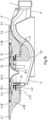
- the drawing shows a section of the floor 1 of a shower tray D.
- shower tray D for example, is a shower tray made of steel enamel.
- the shower tray D has a drain opening 2, which is preferably circular.
- the edge area of the shower tray base surrounding the drain opening has a conical embossing that projects downwards relative to the underside of the base
- the in Figures 1 to 5 shower tray partially shown in the edge region 3 surrounding the drain opening 2 in a ring shape, which extends away from the drain opening 2, does not have any embossing.
- the top of the shower tray disclosed here is thus essentially flat in an edge region 3 surrounding the drain opening 2, which has a circumferential or radial edge width of at least 50 mm, preferably at least 80 mm.
- the top or bottom 1 of the shower tray D is preferably slightly inclined towards the drain opening 2, so that water on the floor 1 flows away towards the drain opening 2.
- the angle of inclination of the bottom top of the shower tray relative to the horizontal is, for example, in a range of 1° to 5°, preferably in the range of 1° to 3°.
- the drain opening 2 of the shower tray D is produced, for example, by laser cutting or punching.
- the drain opening 2 is relatively sharp-edged and delimited by a hole edge 2.1, which has an edge radius in the range of approximately 0.25 mm to 1.25 mm, preferably in the range of approximately 0.5 mm to 1.0 mm.
- An annular flange 4 is arranged on the underside of the shower tray D and surrounds the drain opening 2.
- the flange 4 is assigned to a drain fitting 5 or is part of a drain fitting 5.
- the flange 4 can also be referred to as an adapter flange. It has a connection surface 4.1 intended for placement on the underside of the shower tray.
- the flange 4 is designed in such a way that it can be connected to the shower tray D in a liquid-tight manner without a connecting counterpart resting on the top of the shower tray base 1.
- the flange 4 is cohesively connected to the shower tray.
- the cohesive connection can be achieved, for example, by applying adhesive all around the annular connection surface 4.1 or by using a double-sided adhesive ring.
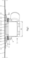
- the drain fitting 5 comprises a drain housing 9 which has an inlet opening 6 and a connection 7 for a drain pipe 8. Furthermore, the drain fitting 5 comprises a cover 10.
- the cover 10 is detachably connected to the flange 4 and/or the drain housing 9 and covers it when installed State the inlet opening 6 of the drain housing 9 with the limitation of an inlet gap 11.
- the flange 4 has a horizontal external dimension or an external diameter A1, which is significantly larger than a horizontal external dimension (e.g. external diameter A2) of the cover 10 that is aligned in the same direction relative to the external dimension of the flange.
- the horizontal external dimension or the outer diameter A1 is at least 5%, preferably at least 15% larger than the horizontal outer dimension (e.g. outer diameter A2) of the cover 10, which is aligned relative to the outer dimension of the flange.
- the flange 4 has a lower inlet surface 4.2 relative to its connection surface 4.1, which, in the assembled state of the drain fitting 5, surrounds the inlet opening 6 of the drain housing 9 and is spaced from the underside of the Cover 10 lies.
- the connection surface 4.1 of the flange is connected in one piece to the inlet surface 4.2 surrounding the inlet opening 6 of the drain housing via a conical inlet surface 4.3.
- the cover 10 has spacers 12 on its underside, with which it rests on the inlet surface 4.2.
- the cover 10 preferably has an enameled decorative panel 10.1 on the top side.
- the decorative panel 10.1 is attached, for example glued, to a support 10.2 having the spacers 12.
- the carrier 10.2 with the downwardly projecting spacers 12 can be made inexpensively from plastic.
- the spacers 12 are dimensioned so that the top of the decorative plate 10.1 of the cover 10 and the top of the edge region 3 of the shower tray surrounding the drain opening 2 are level with each other, preferably flush with each other.
- the cover 10 or the decorative plate 10.1 is preferably slightly curved upwards.
- the drain opening 2 of the shower tray and the cover 10 are relatively large.
- the horizontal external dimension or the external diameter of the decorative panel 10.1 of the cover 10 is at least 130 mm, preferably at least 150 mm, particularly preferably at least 180 mm.
- the drain opening 2 and the cover 10 delimit a circumferential top-side inlet gap 11.1, which has a gap width, for example, in the range of approximately 1.0 mm to 4 mm, preferably in the range of approximately 1.5 mm to 2.5 mm.
- the drain housing 9 has a cup-shaped housing section 9.1, which is adjoined laterally by a substantially S-shaped or wave-shaped drain channel 9.2.
- the drain channel 9.2 is shaped in such a way that it has an overflow edge 9.3, which is significantly higher than a lower inlet edge 9.4, which is formed at the transition from the cup-shaped housing section 9.1 into the drain channel 9.2.
- the vertical distance between the lower inlet edge 9.4 and the overflow edge 9.3 following in the direction of flow defines a sealing water height and is for example approx. 50 mm. Water present in the wave-shaped drain channel 9.2 acts as a sealing water and serves as an odor trap.
- the drain channel 9.2 has a flat channel cross-section between the lower inlet edge 9.4 and the overflow edge 9.3, the width B or horizontal internal dimension of which is a multiple of the channel height H measured orthogonally relative thereto (cf. Figures 1 , 1a and 2 ).
- the width B of the drain channel 9.2 essentially corresponds to that in Fig. 1 shown largest inner width (inner diameter) of the cup-shaped housing section 9.1.
- connection 7 for a drain pipe 8 which follows the overflow edge 9.3 of the drain channel in the flow direction, is preferably designed as a circular cylindrical connecting piece.
- a drain pipe 8 for example in the form of a pipe angle, is inserted into the connection 7.
- An external thread is formed on the outer circumference of the connection 7, onto which a union nut 14 comprising a sealing ring 13 is screwed for the non-positive connection of the drain pipe 8.
- the drain housing 9 can preferably be detachably mounted on the flange (adapter flange) 4.
- the detachable connection is designed, for example, as a screw connection.
- vertically extending threaded sleeves 15 are integrated into the wall of the cup-shaped housing section 9.1, into which fastening screws are screwed.
- the fastening screws are inserted into fastening holes which are arranged evenly spaced apart on a partial circle which surrounds the through opening 4.5 defined by the flange 4, through which water draining from the shower tray base 1 flows into the drain housing 9.
- the fastening holes are formed in the flange 4 or an additional fastening flange that can be inserted into the flange 4 that is connected or connectable to the shower tray.
- the diameter of these mounting holes is smaller than the diameter of the head of the mounting screws inserted therein.
- the spacers 12 of the cover include recesses 16, which form the positive reception of the opposite Inlet surface 4.2 of the flange serves as the heads of the fastening screws protruding upwards.
- the cup-shaped housing section 9.1 of the drain housing has an annular connection surface on its top, on which a sealing ring 17 made of elastomer lies.
- the flange 4 has on its underside a rib structure 4.6 facing the sealing ring 17.
- the rib structure 4.6 can, for example, comprise a plurality of annular, radially spaced, coaxially arranged ribs which press sealingly into the elastic sealing ring 17 after the flange 4 and drain housing 9 have been connected.
- a hair sieve 18 can be arranged below the removable cover 10.
- the hair sieve 18 is preferably inserted into the inlet opening 6 of the drain housing 9 in a removable manner.
- the hair sieve 18 is preferably provided with a cone-shaped, centrally arranged handle 19 (cf. Fig. 1a ).
- FIG. 5 The illustrated embodiment differs from that in the Figures 1 to 4 shown embodiment in that the flange 4 in the area of its connection surface 4.1 has several through holes 4.7 for receiving fasteners 20 connected to the underside of the shower tray base 1.
- the fastening centers 20 are, for example, screw bolts connected to the underside of the shower tray D, onto which fastening nuts are screwed.
- the flange 4 can therefore alternatively or additionally also be non-positively connected to the shower tray D.
- the through holes 4.7 of the flange 4 can also be used to anchor adhesive arranged between the underside of the shower tray base 1 and the connection surface 4.1 of the flange 4.
- a further exemplary embodiment of the invention is shown.
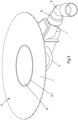
- a shower tray D is shown which is particularly flat, with the bottom 1 of the shower tray D being designed with a slight gradient from the outer edges towards the drain opening 2.
- the angle of inclination of the slope is, for example, in the range of 1° to 3°.
- the drain opening 2 is circular, for example.
- the edge area of the shower tray base surrounding the drain opening has a conical embossing that projects downwards relative to the underside of the base
- the in Figures 6 , 7 and 9 shower tray D shown in the edge region 3 immediately surrounding the drain opening 2, the radial edge width of which is, for example, at least 80 mm, does not have any downwardly projecting embossing. Rather, the edge region 3 surrounding the drain opening 2 is essentially flat.
- a flange 4 is attached to the underside of the shower tray D in the area of the drain opening 2.
- the flange 4 is part of a drain fitting 5 and has an annular connection surface 4.1 intended for connection to the underside of the shower tray base 1 (cf. Fig. 10 , 11 and 12 ).
- the flange 4 is in turn designed in such a way that it can be connected to the shower tray D in a liquid-tight manner without a connecting counterpart resting on the top of the shower tray base 1.
- the flange 4 is or will be cohesively connected to the underside of the shower tray base 1.
- the cohesive, liquid-tight connection can be achieved, for example, by applying adhesive in a ring shape to the connection surface 4.1 or by using a double-sided adhesive ring.
- the flange 4 is preferably designed as a molded part and made of plastic or metal.
- reinforcing ribs 4.81, 4.82 formed, which include, for example, a central, annular reinforcing rib 4.81 and a plurality of radially extending reinforcing ribs 4.82.
- holes or receptacles 4.85 are formed on the underside of the flange 4 for connecting height-adjustable feet. Using the adjustable feet, the floor 1 of the shower tray D or tub can be supported on a raw or screed floor at the installation site.
- the drain fitting 5 has a drain housing 9, which has an inlet opening 6 and a connection 7 for a drain pipe.
- the drain fitting 5 also includes a cover 10.
- the cover 10 is detachably connected to the flange 4 or the drain housing 9 and, in the assembled state, covers the inlet opening 6 of the drain housing 9, delimiting an inlet gap 11.
- the flange 4 has a horizontal external dimension or an external diameter A1, which is significantly larger than the external diameter A2 of the cover 10 or a horizontal external dimension of the cover 10 that is aligned in the same direction relative to the external dimension of the flange.
- the horizontal external dimension or the external diameter is A1 at least 10%, preferably at least 20% larger than the outer diameter A2 of the cover 10 or a horizontal outer dimension of the cover 10 that is aligned in the same direction relative to the outer dimension of the flange 4.
- the flange 4 defines a lower inlet surface 4.2 relative to the connection surface 4.1, which surrounds the inlet opening 6 of the drain housing 9 in the assembled state of the drain fitting 5 and is spaced from the underside of the cover 10.
- the cover 10 is provided on its underside with spacers 12 with which it rests on the inlet surface 4.2.
- a circumferential annular groove 4.30 for receiving an annular seal 26 is formed in the connection surface 4.1 of the flange 4.
- the ring groove 4.30 surrounds it Inlet surface 4.2 and is preferably arranged in the connection surface 4.1 of the flange 4 at a relatively small distance from the inlet surface 4.2, for example with a distance in the range of 2 mm to 15 mm.
- the inlet surface 4.2 which is lower relative to the connection surface 4.1, is inclined, preferably conical, towards the inlet opening 6 of the drain housing.
- the inlet surface 4.2 is limited to the outside by a circumferential shoulder or a circumferential inner wall 4.9.
- the inlet surface 4.2 which is designed with a slope, promotes the flow of water into the drain housing 9.
- the cover 10 has a decorative plate 10.1.
- the preferably enameled decorative panel 10.1 is in turn attached to a support 10.2 which has the spacers 12 and which can be made inexpensively from plastic.
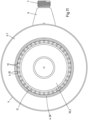
- the cover 10 can be centered on the circumferential wall 4.9 of the flange 4 relative to the drain opening 2 of the shower tray D.
- the spacers 12 are, for example, rib-shaped or web-shaped and protrude radially beyond the outer edge of the cover 10. At least some of the spacers 12 abut with their outer end faces 12.1 against the circumferential shoulder or the circumferential wall 4.9.
- the spacers 12 are designed, for example, in such a way that their ends protruding radially beyond the outer edge of the carrier 10.2 of the decorative plate 10.1 of the cover 10 are inclined towards the outer end face 12.1.
- the circumferential shoulder or the circumferential inner wall 4.9 has a large number of projections 4.10, with the spacers 12 engaging in recesses 4.11 delimited by the projections 4.10. This positive connection prevents or blocks the cover 10 from rotating about a vertical axis relative to the flange 4.
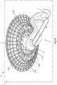
- the cover 10 or the carrier 10.2 of the cover has a tapered liquid guide element 10.3 on the underside, which is designed, for example, in the form of a hyperbolic cone or hyperbolic truncated cone, the tip or taper of the liquid guide element 10.3 protruding into the inlet opening 6 of the drain housing 9.
- the flange 4 has a cylindrical receptacle 4.12, into which a cylindrical connecting piece 9.5 formed on the drain housing 9 is or is inserted.
- the receptacle 4.12 is defined by an inner cylindrical ring web 4.13 of the flange 4.
- the connecting piece 9.5 has ribs or annular grooves 9.6 running parallel to one another on its outside, into which, for example, a sealing ring (O-ring) can be inserted.
- O-ring sealing ring
- a screw flange 21 is provided, by means of which the inlet surface 4.2 of the flange 4 is or will be connected to the drain housing 9.
- the connecting piece 9.5 of the drain housing 9 has an internal thread 9.7 into which the screw flange 21 is screwed.
- An annular shoulder 4.21 is formed on the inlet surface 4.2 for the form-fitting reception of the flange section 21.1 of the screw flange 21.
- the screw flange 21 is provided with handle elements 21.2.
- the handle elements 21.2 enable the screw flange 21 to be screwed without tools into the internal thread 9.7 formed at the inlet opening 6 of the drain housing 9.
- the handle elements 21.2 are designed, for example, in the form of ribs and are arranged on the inside of the screw flange 21.
- the ribs 21.2 preferably protrude radially from the inside of the screw flange 21 and have end edges which from the upper end of the respective rib 21.2 in the direction of the central axis of the screw flange 21 run arcuately downwards.
- the dimensions of the drain opening 2, the cover 10, in particular the decorative plate 10.1, the inlet gap 11.1 and the gap width correspond to those above with reference to those in the Figures 1 to 5 Dimensions shown in the exemplary embodiments shown, so that reference is made to the above description to avoid repetition.
- the drain housing 9 is essentially composed of a lower housing part 9 'and an upper housing part 9", which are or are glued or welded together (cf. Fig. 12 ).
- the illustrated embodiment differs from that in the Figures 6 to 12 shown embodiment in the connection of flange 4 and drain housing 9. Similar to that in Figures 1 to 5
- the exemplary embodiment shown is also in the one in the Figures 7 to 18 shown embodiment threaded sleeves 15 integrated in the wall of the cup-shaped housing section 9.1, into which fastening screws 23 are screwed.
- the fastening screws 23 are combined with a fastening flange 24 which has fastening holes for inserting the fastening screws 23.
- the fastening holes are provided, for example, in radially inwardly projecting ears 24.2 of the fastening flange 24, which is preferably made of stainless steel.
- the fastening screws 23 are countersunk screws. Accordingly, the fastening holes of the fastening flange 24 are essentially conical.
- the cup-shaped housing section 9.1 of the drain housing again has an annular connection surface 9.5' on its upper side, on which a sealing ring 17 made of elastomer lies.
- the flange 4 has one on its underside the sealing ring 17 facing contact surface 4.6 '.
- the contact surface 4.6' can be essentially smooth or in the form of a rib structure, for example a rib structure 4.6 according to Fig. 1a , be trained.
- annular shoulder 4.21 is designed to positively accommodate a flange section 24.1 of the fastening flange 24.
- the cover 10 is again provided with spacers 12 on its underside, with which it rests on the inlet surface 4.2 of the flange.
- the spacers 12 are rib-shaped or web-shaped and protrude beyond the outer edge of the cover 10. At least some of the spacers 12 abut with their outer end faces 12.1 the circumferential shoulder or the circumferential wall 4.9 of the flange.
- the spacers 12 are, for example, designed in such a way that their ends protruding radially beyond the outer edge of the carrier 10.2 of the decorative plate 10.1 of the cover have a step-shaped reduced height towards the outer end face 12.1.
- the spacers 12 according to Fig. 18 wider and define a comparatively coarse star-shaped spoke structure with larger recesses between the spokes or spacers 12.
- FIGS. 15 , 16 and 18 show that the circumferential inner wall 4.9 of the flange has a plurality of projections 4.10, and that the spacers 12 engage in recesses 4.11 delimited by the projections 4.10. This positive connection prevents or blocks the cover 10 from rotating about a vertical axis relative to the flange 4.
- the dimensions of the drain opening 2, the cover 10, the decorative plate 10.1, the inlet gap 11.1 and the gap width correspond to that in the Figures 13 to 18
- the exemplary embodiment shown also corresponds to the dimensions already given above with reference to the other exemplary embodiments, so that to avoid this of repetitions, particularly in the description of the Figures 1 to 5 is referred.
- the drain opening 2 of the shower tray D and the cover 10 can also be rectangular, in particular square, or oval.
Description
Die Erfindung betrifft eine Ablaufarmatur für eine sanitäre Wanne oder Duschtasse, mit einem eine Einlauföffnung und einen Anschluss für ein Ablaufrohr aufweisenden Ablaufgehäuse, mit einem die Einlauföffnung umgehenden Flansch, der eine zur Anordnung in einem Randbereich einer Ablauföffnung der Wanne oder Duschtasse bestimmte Anschlussfläche aufweist, und mit einer Abdeckhaube, welche lösbar mit dem Flansch und/oder dem Ablaufgehäuse verbunden ist und im montierten Zustand die Einlauföffnung unter Begrenzung eines Einlaufspaltes abdeckt, wobei der Flansch, der vorzugsweise ringförmig ausgebildet ist, ein horizontales Außenmaß aufweist, welches größer ist als ein relativ zu dem Außenmaß des Flansches gleichgerichtetes, horizontales Außenmaß der Abdeckhaube. Der Flansch ist derart ausgeführt, dass er ohne ein an der Oberseite des Wannen- oder Duschtassenbodens anliegendes Verbindungsgegenstück mit der Unterseite der Wanne oder Duschtasse verbindbar ist. Der Flansch und/oder das Ablaufgehäuse weist eine zu der Anschlussfläche des Flansches tieferliegende Einlauffläche auf, welche im montierten Zustand der Ablaufarmatur die Einlauföffnung umgibt und beabstandet zu der Unterseite der Abdeckhaube liegt, wobei die Abdeckhaube an ihrer Unterseite Abstandhalter aufweist, mit denen sie auf der Einlauffläche aufliegt. Die Erfindung betrifft insbesondere die Verwendung einer solchen Ablaufarmatur in Kombination mit einer sanitären Wanne oder Duschtasse, wobei die Ablaufarmatur an einer Ablauföffnung der Wanne oder Duschtasse befestigt wird.The invention relates to a drain fitting for a sanitary tub or shower tray, with a drain housing having an inlet opening and a connection for a drain pipe, with a flange surrounding the inlet opening, which has a connection surface intended for arrangement in an edge region of a drain opening of the tub or shower tray, and with a cover, which is detachably connected to the flange and / or the drain housing and, in the assembled state, covers the inlet opening while delimiting an inlet gap, the flange, which is preferably annular, having a horizontal external dimension which is larger than a relative to Horizontal external dimension of the cover, which is the same as the external dimension of the flange. The flange is designed in such a way that it can be connected to the underside of the tub or shower tray without a connecting counterpart resting on the top of the tub or shower tray base. The flange and/or the drain housing has an inlet surface which is lower than the connecting surface of the flange and which, when the drain fitting is assembled, surrounds the inlet opening and is spaced from the underside of the cover, the cover having spacers on its underside with which it is on the inlet surface rests. The invention relates in particular to the use of such a drain fitting in combination with a sanitary tub or shower tray, the drain fitting being attached to a drain opening of the tub or shower tray.
Eine derartige Ablaufarmatur ist bekannt (vgl.
Eine Duschtasse im Kontext der vorliegenden Erfindung kann auch als Duschwanne bezeichnet werden.A shower tray in the context of the present invention can also be referred to as a shower tray.
Herkömmliche Badewannen sowie Duschtassen sind aus Stahl-Email oder faserverstärktem Kunststoff hergestellt und weisen in einem Randbereich der Ablauföffnung der Wanne oder Duschtasse eine Mulde oder umlaufende Vertiefung auf (vgl. z. B.
Insbesondere bei Duschtassen aus Stahl-Email lässt sich die umlaufende Vertiefung im Randbereich der Ablauföffnung in der Regel nur mit relativ großen Biegeradien verwirklichen. Denn aufgrund der Umformeigenschaften von für Badewannen oder Duschtassen geeignetem Stahlblech und durch den Umformprozess besteht die Notwendigkeit von materialabhängigen Mindestbiegeradien. Relativ kleine Biegeradien, insbesondere kantige Konturen an der Ablauföffnung und geringe Ablaufspaltmaße können durch den üblichen Umformprozess bei Wannen und Duschtassen aus Stahl-Email nicht oder kaum hergestellt werden. Der Spielraum für die Formgestaltung einer Wanne und Duschtasse aus Stahl-Email ist aufgrund der fertigungstechnischen Mindestradien erheblich eingeschränkt.Especially with shower trays made of steel enamel, the circumferential recess in the edge area of the drain opening can usually only be achieved with relatively large bending radii. Because of the forming properties of sheet steel suitable for bathtubs or shower trays and the forming process, there is a need for material-dependent minimum bending radii. Relatively small bending radii, in particular angular contours at the drain opening and small drain gap dimensions, cannot or can hardly be produced using the usual forming process for tubs and shower trays made of steel enamel. The scope for the design of a tub and shower tray made of steel enamel is considerably limited due to the minimum radii required for production.
Die
Die
Davon ausgehend liegt der Erfindung die Aufgabe zugrunde, eine Ablaufarmatur der eingangs genannten Art zu schaffen, die insbesondere bei Duschtassen aus Stahl-Email den Spielraum für die Formgestaltung der Duschtassen deutlich erweitert und dabei ein Drehen der Abdeckhaube um eine vertikale Achse relativ zu dem Flansch sowie dem Ablaufgehäuse verhindert oder sperrt.Proceeding from this, the invention is based on the object of creating a drain fitting of the type mentioned, which significantly expands the scope for the shape of the shower trays, particularly in shower trays made of steel enamel, and thereby allows the cover to be rotated about a vertical axis relative to the flange prevents or blocks the drain housing.
Gelöst wird diese Aufgabe durch eine Ablaufarmatur mit den in Anspruch 1 angegebenen Merkmalen. Vorteilhafte Ausgestaltungen der erfindungsgemäßen Ablaufarmatur sind in den auf Anspruch 1 rückbezogenen Unteransprüchen angegeben.This task is solved by a drain fitting with the features specified in
Die vorliegende Erfindung basiert auf der Idee, Designteile einer Badewanne oder Duschtasse, insbesondere einer solchen aus Stahl-Email, im Bereich der Ablauföffnung durch flächige Bauteile bzw. Bodenabschnitte ohne starken Umformungsgrad herzustellen. Alle oder nahezu alle Funktionsteile im Bereich der Ablauföffnung sollen dabei in den nicht sichtbaren Bereich unter der Abdeckhaube (Ablaufhaube) angeordnet und damit verborgen werden.The present invention is based on the idea of producing design parts of a bathtub or shower tray, in particular one made of steel enamel, in the area of the drain opening using flat components or base sections without a strong degree of deformation. All or almost all functional parts in the area of the drain opening should be arranged in the invisible area under the cover (drain hood) and thus hidden.
Die erfindungsgemäße Ablaufarmatur ist dadurch gekennzeichnet, dass der Flansch eine Vielzahl von Vorsprüngen aufweist, wobei die Abstandhalter in von den Vorsprüngen begrenzte Ausnehmungen eingreifen, oder dass die Einlauffläche nach außen durch einen umlaufenden Absatz oder eine umlaufende innere Wandung begrenzt ist, wobei der Absatz oder die Wandung eine Vielzahl von Vorsprüngen aufweist, und wobei die Abstandhalter in von den Vorsprüngen begrenzte Ausnehmungen eingreifen. Durch diese formschlüssige Verbindung wird ein Drehen der Abdeckhaube um eine vertikale Achse relativ zu dem Flansch sowie dem Ablaufgehäuse verhindert oder gesperrt.The drain fitting according to the invention is characterized in that the flange has a plurality of projections, with the spacers engaging in recesses delimited by the projections, or in that the inlet surface is delimited to the outside by a circumferential shoulder or a circumferential inner wall, with the shoulder or the Wall has a plurality of projections, and wherein the spacers engage in recesses delimited by the projections. This positive connection prevents or blocks the cover from rotating about a vertical axis relative to the flange and the drain housing.
Die erfindungsgemäße Ablaufarmatur erweitert den Spielraum für die Formgestaltung einer Duschtasse, insbesondere einer Duschtasse aus Stahl-Email deutlich. Denn die erfindungsgemäße Ablaufarmatur erfordert für ihre Fixierung an einer Duschtasse oder Wanne keine umlaufende Vertiefung in einem Randbereich der Ablauföffnung der Duschtasse oder Wanne. Vielmehr bietet die erfindungsgemäße Ablaufarmatur die Möglichkeit, die Designteile im Bereich der Ablauföffnung der Duschtasse oder Wanne durch flächige Bauteile ohne starken Umformungsgrad herzustellen. Alle Funktionsteile im Bereich der Ablauföffnung können dabei in den nicht sichtbaren Bereich unter der Abdeckhaube angeordnet und damit verborgen werden.The drain fitting according to the invention significantly expands the scope for the design of a shower tray, in particular a shower tray made of steel enamel. Because the drain fitting according to the invention does not require a circumferential recess in an edge region of the drain opening of the shower tray or tub in order to be fixed to a shower tray or tub. Rather, the drain fitting according to the invention offers the possibility of producing the design parts in the area of the drain opening of the shower tray or tub using flat components without a strong degree of deformation. All functional parts in the area of the drain opening can be arranged in the invisible area under the cover and thus hidden.
Die Oberseite der Abdeckhaube ist im montierten, bestimmungsgemäßen Zustand der Ablaufarmatur für einen Betrachter typischerweise gut sichtbar. Die Oberseite der Abdeckhaube kann daher auch als dekorative Oberseite bezeichnet werden oder ist als dekorative Oberseite ausgeführt. Die dekorative Oberseite der Abdeckhaube kann beispielsweise durch eine an der Oberseite der Abdeckhaube angeordnete Dekorplatte realisiert sein. Die Oberseite der Abdeckhaube bzw. Dekorplatte kann im Wesentlichen eben oder geringfügig nach oben gewölbt ausgebildet sein. Im montierten, bestimmungsgemäßen Zustand der Ablaufarmatur liegen die Oberseite der Abdeckhaube bzw. Dekorplatte und die Oberseite des die Ablauföffnung umgebenden Randbereichs der sanitären Wanne oder Duschtasse im Wesentlichen bodengleich, vorzugsweise im Wesentlichen flächenbündig zueinander.The top of the cover is typically clearly visible to an observer when the drain fitting is installed and in the intended state. The top of the cover can therefore also be referred to as a decorative top or is designed as a decorative top. The decorative top of the cover can be realized, for example, by a decorative plate arranged on the top of the cover. The top of the cover or decorative panel can be essentially flat or slightly curved upwards. In the When the drain fitting is assembled, as intended, the top of the cover or decorative plate and the top of the edge area of the sanitary tub or shower tray surrounding the drain opening are essentially level with the floor, preferably essentially flush with one another.
Vorzugsweise ist das horizontale Außenmaß des Flansches der erfindungsgemäßen Ablaufarmatur um mindestens 5%, bevorzugt um mindestens 10%, besonders bevorzugt um mindestens 15% größer als das relativ zu dem Außenmaß des Flansches gleichgerichtete, horizontale Außenmaß der Abdeckhaube.Preferably, the horizontal external dimension of the flange of the drain fitting according to the invention is at least 5%, preferably at least 10%, particularly preferably at least 15% larger than the horizontal external dimension of the cover, which is oriented in the same direction relative to the external dimension of the flange.
Die Ablauföffnung der Duschtasse oder Wanne sowie die Abdeckhaube sind vorzugsweise kreisförmig ausgeführt. Das oben angegebene horizontale Außenmaß kann dann auch als horizontaler Außendurchmesser bezeichnet werden.The drain opening of the shower tray or tub as well as the cover are preferably circular. The horizontal outside dimension specified above can then also be referred to as the horizontal outside diameter.
Erfindungsgemäß weist der Flansch und/oder das Ablaufgehäuse eine relativ zu der Anschlussfläche des Flansches tieferliegende Einlauffläche auf, welche im montierten Zustand der Ablaufarmatur die Einlauföffnung des Ablaufgehäuses umgibt und beabstandet zu der Unterseite der Abdeckhaube liegt. Hierdurch lassen sich Funktionsteile der Ablaufarmatur in günstiger Weise unter der Abdeckhaube anordnen und damit verbergen. Insbesondere ermöglicht diese Ausgestaltung eine einfache und funktionsgerechte Lagerung sowie vertikale Positionierung der Abdeckhaube. Hierzu weist die Abdeckhaube an ihrer Unterseite Abstandhalter auf, mit denen sie auf der Einlauffläche aufliegt.According to the invention, the flange and/or the drain housing has an inlet surface which is lower relative to the connecting surface of the flange and which, in the assembled state of the drain fitting, surrounds the inlet opening of the drain housing and is spaced from the underside of the cover. This allows functional parts of the drain fitting to be conveniently arranged under the cover and thus hidden. In particular, this configuration enables simple and functional storage and vertical positioning of the cover. For this purpose, the cover has spacers on its underside with which it rests on the inlet surface.
Eine vorteilhafte Ausgestaltung der erfindungsgemäßen Ablaufarmatur ist dadurch gekennzeichnet, dass in der Anschlussfläche des Flansches eine umlaufende Ringnut zur Aufnahme einer Ringdichtung, beispielsweise einer ringförmigen Elastomerdichtung, ausgebildet ist. Die Ringnut umgibt die Einlauffläche und ist vorzugsweise mit relativ geringem Abstand von der Einlauffläche, beispielsweise mit einem Abstand im Bereich von 2 mm bis 15 mm, insbesondere im Bereich von 3 bis 10 mm, in der Anschlussfläche des Flansches angeordnet. Eine in die Ringnut eingelegte Ringdichtung stellt insbesondere auch bei anschließender Verklebung der Anschlussfläche des Flansches mit der Unterseite des Wannen- oder Duschtassenbodens eine zuverlässige Flüssigkeitsabdichtung zwischen Duschtasse bzw. Wanne und Ablaufarmatur sicher. Insbesondere kann durch diese Ausgestaltung sichergestellt werden, dass das Klebemittel gegenüber dem Wasserablaufbereich der Ablaufarmatur wirksam abgedichtet ist, so dass Dusch- oder Badewasser nicht zu dem Klebemittel gelangen kann.An advantageous embodiment of the drain fitting according to the invention is characterized in that a circumferential annular groove for receiving an annular seal, for example an annular elastomer seal, is formed in the connecting surface of the flange. The annular groove surrounds the inlet surface and is preferably arranged in the connection surface of the flange at a relatively small distance from the inlet surface, for example with a distance in the range of 2 mm to 15 mm, in particular in the range of 3 to 10 mm. One inserted into the ring groove The ring seal ensures a reliable liquid seal between the shower tray or tub and the drain fitting, especially when the connecting surface of the flange is subsequently glued to the underside of the tub or shower tray base. In particular, this configuration can ensure that the adhesive is effectively sealed from the water drain area of the drain fitting, so that shower or bath water cannot reach the adhesive.
Nach einer weiteren vorteilhaften Ausgestaltung der erfindungsgemäßen Ablaufarmatur ist die Anschlussfläche des Flansches über eine konische Einlauffläche einstückig mit der die Einlauföffnung des Ablaufgehäuses umgebenden Einlauffläche verbunden. Durch die konische Einlauffläche wird das Abfließen von Wasser in das Ablaufgehäuse begünstigt und ein Anhaften von Schmutz auf der Einlauffläche weitgehend verhindert. Des Weiteren lässt sich die Abdeckhaube mittels der konischen Einlauffläche einfach und zuverlässig in der Ablauföffnung der Wanne zentrieren. Hierzu weisen die an der Unterseite der Abdeckhaube ausgebildeten Abstandshalter vorzugsweise an ihren äußeren Abschnitten abgeschrägte Kanten auf, wobei die jeweilige abgeschrägte Kante relativ zu einer horizontalen Ebene einen Winkel definiert, der im Wesentlichen dem Neigungswinkel der konischen Einlauffläche entspricht. Anders ausgedrückt, verläuft die abgeschrägte Kante des Abstandshalters im Wesentlichen konturparallel zu der konischen Einlauffläche.According to a further advantageous embodiment of the drain fitting according to the invention, the connecting surface of the flange is connected in one piece to the inlet surface surrounding the inlet opening of the drain housing via a conical inlet surface. The conical inlet surface promotes the flow of water into the drain housing and largely prevents dirt from sticking to the inlet surface. Furthermore, the cover can be easily and reliably centered in the drain opening of the tub using the conical inlet surface. For this purpose, the spacers formed on the underside of the cover preferably have beveled edges on their outer sections, the respective beveled edge defining an angle relative to a horizontal plane which essentially corresponds to the angle of inclination of the conical inlet surface. In other words, the beveled edge of the spacer runs essentially parallel to the contour of the conical inlet surface.
Eine andere vorteilhafte Ausgestaltung der erfindungsgemäßen Ablaufarmatur ist dadurch gekennzeichnet, dass die relativ zu der Anschlussfläche des Flansches tieferliegende Einlauffläche geneigt, vorzugsweise konisch, zu der Einlauföffnung des Ablaufgehäuses hin ausgebildet ist. Die Einlauffläche ist dabei nach außen durch einen umlaufenden Absatz oder eine umlaufende innere Wandung begrenzt. Durch die geneigt, vorzugsweise konisch ausgebildete Einlauffläche wird das Abfließen von Wasser in das Ablaufgehäuse begünstigt und ein Anhaften von Schmutz auf der Einlauffläche weitgehend verhindert. Auch lässt sich die Abdeckhaube an dem umlaufenden Absatz oder an der umlaufenden inneren Wandung einfach und zuverlässig relativ zu der Ablauföffnung der Wanne zentrieren. Hierzu weist die Abdeckhaube an ihrer Unterseite beispielsweise eine Vielzahl von Abstandshaltern, beispielsweise rippen- oder stegförmiger Abstandshalter auf, die radial über die Außenkante der Abdeckhaube hinaus vorstehen. Die äußeren Stirnseiten der Abstandhalter stoßen dabei gegen den umlaufenden Absatz bzw. die umlaufende innere Wandung oder enden mit sehr geringem Spiel relativ zu dem Absatz bzw. der inneren Wandung. Des Weiteren sind die Abstandhalter vorzugsweise derart ausgebildet, dass ihre radial über die Außenkante der Abdeckhaube bzw. über die Außenkante eines Trägers einer Dekorplatte der Abdeckhaube hinaus vorstehenden Enden zur äußeren Stirnseite hin geneigt oder abgestuft sind. Hierdurch sind die Abstandhalter durch den Einlaufspalt hindurch kaum sichtbar, was für das ästhetische Design des Einlaufspaltes von Vorteil ist. Allerdings wird durch diese Ausgestaltung bei geringer Breite des Einlaufspaltes auch die Ablaufleistung der Ablaufarmatur optimiert.Another advantageous embodiment of the drain fitting according to the invention is characterized in that the inlet surface, which is lower relative to the connecting surface of the flange, is designed to be inclined, preferably conical, towards the inlet opening of the drain housing. The inlet surface is limited to the outside by a circumferential shoulder or a circumferential inner wall. The inclined, preferably conical inlet surface facilitates the flow of water into the drain housing and largely prevents dirt from adhering to the inlet surface. The cover can also be easily attached to the surrounding shoulder or to the surrounding inner wall center reliably relative to the drain opening of the tub. For this purpose, the cover has, for example, a large number of spacers on its underside, for example rib-shaped or web-shaped spacers, which protrude radially beyond the outer edge of the cover. The outer end faces of the spacers abut against the circumferential shoulder or the circumferential inner wall or end with very little play relative to the shoulder or the inner wall. Furthermore, the spacers are preferably designed in such a way that their ends protruding radially beyond the outer edge of the cover or beyond the outer edge of a support of a decorative plate of the cover are inclined or stepped towards the outer end face. As a result, the spacers are barely visible through the inlet gap, which is an advantage for the aesthetic design of the inlet gap. However, this design also optimizes the drain performance of the drain fitting with a small width of the inlet gap.
Die Abdeckhaube oder die auf dem Träger angebrachte Dekorplatte hat vorzugsweise eine geschlossene oder im Wesentlichen geschlossene Oberseite. Unter einer im Wesentlichen geschlossenen Oberseite ist im vorliegenden Kontext eine Oberseite gemeint, die optional eine einzige oder mehrere Durchgangsöffnungen aufweist, wobei der Flächenanteil der Durchgangsöffnung oder Durchgangsöffnungen an der Gesamtfläche der Oberseite der Abdeckhaube oder Dekorplatte maximal 2% beträgt.The cover or the decorative panel attached to the carrier preferably has a closed or substantially closed top side. In the present context, a substantially closed top side means a top side which optionally has a single or multiple through-openings, whereby the surface area of the through-opening or through-openings in the total area of the top of the cover or decorative panel is a maximum of 2%.
Eine weitere vorteilhafte Ausgestaltung der erfindungsgemäßen Ablaufarmatur ist dadurch gekennzeichnet, dass an der Einlauffläche ein ringförmiger Absatz zur formschlüssigen Aufnahme eines Flanschabschnitts eines Befestigungsflansches, insbesondere eines Schraubflansches ausgebildet ist. Hierdurch kann der Übergang von der Einlauffläche zu dem Befestigungs- oder Schraubflansch im Wesentlichen flächenbündig, vorzugsweise ohne nach oben vorstehenden Vorsprung, ausgeführt werden. Somit können Ablagerungen am Übergang von der Einlauffläche zu dem Schraubflansch weitgehend verhindert werden.A further advantageous embodiment of the drain fitting according to the invention is characterized in that on the inlet surface there is an annular shoulder for positively receiving a flange section of a fastening flange, in particular a screw flange is formed. As a result, the transition from the inlet surface to the fastening or screw flange can be carried out essentially flush with the surface, preferably without an upwardly projecting projection. This means that deposits at the transition from the inlet surface to the screw flange can be largely prevented.
Nach einer weiteren Ausgestaltung der Erfindung ist die die Einlauföffnung des Ablaufgehäuses umgebende Einlauffläche mittels eines Schraubflansches mit dem Ablaufgehäuse verbunden. Diese Ausgestaltung ermöglicht eine Reduzierung der Anzahl der Bauteile der Ablaufarmatur, indem anstelle eines Befestigungsflansches mit mehreren Befestigungsschrauben und einer entsprechenden Anzahl von im Ablaufgehäuse eingegossenen Gewindehülsen lediglich ein einzelner Schraubflansch verwendet wird, der in ein an der Einlauföffnung des Ablaufgehäuses ausgebildetes Innengewinde eingeschraubt wird.According to a further embodiment of the invention, the inlet surface surrounding the inlet opening of the drain housing is connected to the drain housing by means of a screw flange. This configuration makes it possible to reduce the number of components of the drain fitting by using only a single screw flange instead of a fastening flange with several fastening screws and a corresponding number of threaded sleeves cast into the drain housing, which is screwed into an internal thread formed at the inlet opening of the drain housing.
Vorzugsweise weist der Schraubflansch Griffelemente auf. Somit lässt sich der Schraubflansch werkzeuglos in das an der Einlauföffnung des Ablaufgehäuses ausgebildete Innengewinde einschrauben. Die Griffelemente sind beispielsweise in Form von Rippen ausgebildet, die an der Innenseite und/oder der Oberseite des Schraubflansches angeordnet sind. Der Schraubflansch weist beispielsweise zwei, drei oder vier solcher Griffelemente (Rippen) auf, die gleichmäßig voneinander beabstandet sind. Vorzugsweise stehen die Rippen radial von der Innenseite des Schraubflansches ab und weisen jeweils eine Stirnkante auf, die vom oberen Ende der jeweiligen Rippe aus in Richtung der Mittelachse des Schraubflansches bogenförmig nach unten verläuft.The screw flange preferably has grip elements. The screw flange can thus be screwed into the internal thread formed at the inlet opening of the drain housing without tools. The grip elements are designed, for example, in the form of ribs which are arranged on the inside and/or the top of the screw flange. The screw flange has, for example, two, three or four such grip elements (ribs) that are evenly spaced from one another. Preferably, the ribs protrude radially from the inside of the screw flange and each have an end edge which arcs downwards from the upper end of the respective rib in the direction of the central axis of the screw flange.
Eine weitere vorteilhafte Ausgestaltung der erfindungsgemäßen Ablaufarmatur ist dadurch gekennzeichnet, dass der Flansch im Bereich seiner Anschlussfläche mehrere Durchgangslöcher zur Aufnahme von mit der Unterseite der Duschtasse oder Wanne verbundenen Befestigungsmitteln oder zur Verankerung von Klebstoff aufweist. Hierdurch lässt sich eine besonders zuverlässige Fixierung der Ablaufarmatur an der Duschtasse oder Wanne erzielen. Bei den mit der Unterseite der Duschtasse oder Wanne verbundenen Befestigungsmitteln kann es sich beispielsweise um Schraubbolzen oder Rastbolzen handeln.A further advantageous embodiment of the drain fitting according to the invention is characterized in that the flange has a plurality of through holes in the area of its connection surface for receiving fasteners connected to the underside of the shower tray or tub or for anchoring adhesive. This allows a particularly reliable fixation of the drain fitting on the Shower tray or tub. The fasteners connected to the underside of the shower tray or tub can be, for example, screw bolts or locking bolts.
Das horizontale Außenmaß der Abdeckhaube beträgt nach einer weiteren vorteilhaften Ausgestaltung der erfindungsgemäßen Ablaufarmatur beispielsweise mindestens 130 mm, vorzugsweise mindestens 150 mm, besonders bevorzugt mindestens 180 mm. Die Ablauföffnung der Duschtasse oder Wanne hat dabei ein etwas größeres Außenmaß als die Abdeckhaube. Hierdurch lässt sich eine hohe Ablaufleistung bei einem relativ schmalen Einlaufspalt erzielen. Die Spaltbreite (Spaltmaß) des Einlaufspaltes liegt beispielsweise im Bereich von 1,0 mm bis 2,5 mm, insbesondere bei ca. 2 mm. Vorzugsweise sind die Abdeckhaube und die Ablauföffnung der Duschtasse oder Wanne jeweils kreisrund ausgebildet. Der dann kreisförmige Einlaufspalt ist in strömungstechnischer Hinsicht ideal.According to a further advantageous embodiment of the drain fitting according to the invention, the horizontal external dimension of the cover is, for example, at least 130 mm, preferably at least 150 mm, particularly preferably at least 180 mm. The drain opening of the shower tray or tub has a slightly larger external dimension than the cover. This allows a high drainage performance to be achieved with a relatively narrow inlet gap. The gap width (gap dimension) of the inlet gap is, for example, in the range from 1.0 mm to 2.5 mm, in particular approximately 2 mm. Preferably, the cover and the drain opening of the shower tray or tub are each circular. The then circular inlet gap is ideal from a flow perspective.
Eine weitere vorteilhafte Ausgestaltung der erfindungsgemäßen Ablaufarmatur sieht vor, dass die Abdeckhaube oberseitig eine emaillierte Dekorplatte aufweist. Die Abdeckhaube vermittelt im montierten Zustand somit einen hochwertigen Eindruck. Die Abdeckhaube umfasst dabei einen Träger, auf dessen Oberseite die Dekorplatte angeordnet und mit dem Träger fest verbunden ist. Der Träger, der unterseitig mit den oben erwähnten Abstandshaltern versehen ist, kann kostengünstig zum Beispiel aus Kunststoff gefertigt sein. Die emaillierte Dekorplatte hat hervorragende Hygieneeigenschaften. Die Dekorplatte kann farblich der sichtbaren Oberfläche der Duschtasse oder Wanne entsprechen, so dass die Duschtasse oder Wanne dann im Bereich der Ablauföffnung ein unauffälliges, dezentes Design besitzt.A further advantageous embodiment of the drain fitting according to the invention provides that the cover has an enamelled decorative plate on the top side. When installed, the cover gives a high-quality impression. The cover includes a support, on the top of which the decorative panel is arranged and is firmly connected to the support. The carrier, which is provided on the underside with the above-mentioned spacers, can be made inexpensively, for example from plastic. The enameled decorative panel has excellent hygiene properties. The color of the decorative plate can match the visible surface of the shower tray or tub, so that the shower tray or tub then has an inconspicuous, subtle design in the area of the drain opening.
Nach einer weiteren Ausgestaltung weist der Träger der Abdeckhaube an seiner Unterseite ein sich nach unten verjüngendes Flüssigkeitsleitelement auf, das vorzugsweise in Form eines Kegels, Kegelstumpfs, hyperbolischen Kegels oder hyperbolischen Kegelstumpfs ausgebildet ist, wobei die Spitze oder Verjüngung des Flüssigkeitsleitelements vorzugsweise in die Einlauföffnung des Ablaufgehäuses ragt.According to a further embodiment, the support of the cover has on its underside a downwardly tapering liquid guide element, which is preferably designed in the form of a cone, truncated cone, hyperbolic cone or hyperbolic truncated cone, the tip or taper of the liquid guide element preferably entering the inlet opening of the drain housing protrudes.
Eine weitere vorteilhafte Ausgestaltung der erfindungsgemäßen Ablaufarmatur ist dadurch gekennzeichnet, dass an der Unterseite des Flansches mehrere Löcher oder Aufnahmen zur Anbindung von Stellfüßen, vorzugsweise höhenverstellbaren Stellfüßen, ausgebildet sind. Mittels der Stellfüße lässt sich der Boden der Duschtasse oder Wanne auf einem Roh- oder Estrichboden am Aufstellungsort optimal abstützen.A further advantageous embodiment of the drain fitting according to the invention is characterized in that several holes or receptacles for connecting adjustable feet, preferably height-adjustable adjustable feet, are formed on the underside of the flange. Using the adjustable feet, the base of the shower tray or tub can be optimally supported on a raw or screed floor at the installation site.
Nach einer weiteren Ausgestaltung der erfindungsgemäßen Ablaufarmatur ist der Flansch im montierten Zustand der Ablaufarmatur lösbar mit dem Ablaufgehäuse verbunden. Diese Ausgestaltung der Ablaufgarnitur ist sowohl in fertigungstechnischer Hinsicht als auch in montagetechnischer Hinsicht vorteilhaft.According to a further embodiment of the drain fitting according to the invention, the flange is detachably connected to the drain housing when the drain fitting is assembled. This design of the drain fitting is advantageous both in terms of production technology and in terms of assembly technology.
Eine weitere Ausgestaltung der erfindungsgemäßen Ablaufarmatur sieht vor, dass in die Einlauföffnung ein herausnehmbares Haarsieb eingesetzt ist. Hierdurch lassen sich Verstopfungen eines in dem Ablaufgehäuse ausgebildeten Geruchverschlusses verhindern. Das Haarsieb hat vorzugsweise eine im Wesentlichen napf- oder schüsselförmige Form und weist eine Vielzahl kleiner Durchgangsöffnungen auf. Vorzugsweise sind die kleinen Durchgangsöffnungen spaltförmig ausgeführt. Für eine Reinigung des Haarsiebes ist dieses vorzugsweise mit einem Griff, vorzugsweise einem mittig angeordneten, knopf- oder zapfenförmigen Griff versehen, so dass das Haarsieb zu Reinigungszwecken auf einfache Weise aus der Einlauföffnung entnommen und nach der Reinigung wieder in die Einlauföffnung eingesetzt werden kann.A further embodiment of the drain fitting according to the invention provides that a removable hair strainer is inserted into the inlet opening. This makes it possible to prevent blockages of an odor trap formed in the drain housing. The hair sieve preferably has a substantially cup or bowl-shaped shape and has a large number of small through openings. The small through openings are preferably designed to be gap-shaped. For cleaning the hair sieve, it is preferably provided with a handle, preferably a centrally arranged, button or peg-shaped handle, so that the hair sieve can be easily removed from the inlet opening for cleaning purposes and can be reinserted into the inlet opening after cleaning.
Das Ablaufgehäuse der erfindungsgemäßen Ablaufarmatur weist vorzugsweise einen Siphon oder Geruchverschluss auf, beispielsweise einen im Wesentlichen S-förmigen oder wellenförmigen Ablaufkanal.The drain housing of the drain fitting according to the invention preferably has a siphon or odor trap, for example a substantially S-shaped or wave-shaped drain channel.
Wie voranstehend dargelegt, ist die vorliegende Erfindung insbesondere auf eine Verwendung der erfindungsgemäßen Ablaufarmatur in Kombination mit einer sanitären Wanne oder Duschtasse gerichtet, wobei die Wanne oder Duschtasse in ihrem Boden eine Ablauföffnung aufweist, wobei ein sich von der Ablauföffnung von dieser weg erstreckender Randbereich des Bodens im Wesentlichen flach ausgebildet ist und/oder keine umlaufende Prägung aufweist, und wobei die Ablaufarmatur an der Ablauföffnung ohne ein an der Oberseite des Wannen- oder Duschtassenbodens anliegendes Verbindungsgegenstück mit der Unterseite der Wanne oder Duschtasse verbunden wird.As explained above, the present invention is particularly aimed at using the drain fitting according to the invention in combination with a sanitary tub or shower tray, the tub or shower tray being in has a drain opening at its base, wherein an edge region of the base extending away from the drain opening is essentially flat and/or has no circumferential embossing, and wherein the drain fitting rests on the drain opening without resting on the top of the tub or shower tray base Connection counterpart is connected to the underside of the tub or shower tray.
Nachfolgend wird die Erfindung anhand einer mehrere Ausführungsbeispiele darstellenden Zeichnung näher erläutert. Es zeigen:
- Fig. 1
- einen Abschnitt einer Duschtasse mit einer erfindungsgemäßen Ablaufarmatur in einer ersten vertikalen Schnittansicht;
- Fig. 1a
- eine Ablaufarmatur gemäß
Fig. 1 mit einem darin eingesetzten Haarsieb, wiederum in einer vertikalen Schnittansicht; - Fig. 2
- den Abschnitt der Duschtasse mit der Ablaufarmatur aus
Fig. 1 in einer zweiten vertikalen Schnittansicht, die rechtwinklig zu der ersten vertikalen Schnittansicht verläuft; - Fig. 3
- den Abschnitt der Duschtasse mit der Ablaufarmatur aus
den Figuren 1 und2 in einer perspektivischen Draufsicht; - Fig. 4
- den Abschnitt der Duschtasse mit der Ablaufarmatur aus
den Figuren 1 und2 in einer perspektivischen Unteransicht; - Fig. 5
- einen Abschnitt einer Duschtasse mit einer erfindungsgemäßen Ablaufarmatur in einem weiteren Ausführungsbeispiel, in einer perspektivischen Unteransicht;
- Fig. 6
- eine Duschtasse mit einer erfindungsgemäßen Ablaufarmatur in einem weiteren Ausführungsbeispiel, in einer perspektivischen Draufsicht;
- Fig. 7
- die Duschtasse mit der Ablaufarmatur aus
Fig. 6 in einer perspektivischen Unteransicht; - Fig. 8
- die Ablaufarmatur aus
Fig. 7 , ohne Duschtasse, in einer Längsseitenansicht; - Fig. 9
- die Ablaufarmatur aus
Fig. 8 mit Duschtasse in einer vertikalen Schnittansicht; - Fig. 10
- die Ablaufarmatur aus
Fig. 8 , ohne Duschtasse, in einer vertikalen Schnittansicht; - Fig. 11
- die Ablaufarmatur aus
Fig. 8 , ohne Duschtasse, in Draufsicht; - Fig. 12
- die Ablaufarmatur
aus den Figuren 8 und11 in einer perspektivischen Explosionsdarstellung; - Fig. 13
- einen Duschtassenabschnitt mit einer erfindungsgemäßen Ablaufarmatur in einem weiteren Ausführungsbeispiel, in einer perspektivischen Unteransicht;
- Fig. 14
- die Ablaufarmatur aus
Fig. 13 , ohne Duschtasse, in einer Längsseitenansicht; - Fig. 15
- die Ablaufarmatur aus
Fig. 14 mit Duschtassenabschnitt in einer vertikalen Schnittansicht; - Fig. 16
- die Ablaufarmatur aus
Fig. 14 , ohne Duschtasse, in einer vertikalen Schnittansicht; - Fig. 17
- die Ablaufarmatur aus
Fig. 14 , ohne Duschtasse, in Draufsicht; und - Fig. 18
- die Ablaufarmatur
aus den Figuren 14 und17 in einer perspektivischen Explosionsdarstellung.
- Fig. 1
- a section of a shower tray with a drain fitting according to the invention in a first vertical sectional view;
- Fig. 1a
- a drain fitting in accordance with
Fig. 1 with a hair sieve inserted therein, again in a vertical sectional view; - Fig. 2
- the section of the shower tray with the drain fitting
Fig. 1 in a second vertical sectional view that is perpendicular to the first vertical sectional view; - Fig. 3
- Remove the section of the shower tray with the drain fitting
Figures 1 and2 in a perspective top view; - Fig. 4
- Remove the section of the shower tray with the drain fitting
Figures 1 and2 in a perspective bottom view; - Fig. 5
- a section of a shower tray with a drain fitting according to the invention in a further exemplary embodiment, in a perspective bottom view;
- Fig. 6
- a shower tray with a drain fitting according to the invention in a further exemplary embodiment, in a perspective top view;
- Fig. 7
- the shower tray with the drain fitting
Fig. 6 in a perspective bottom view; - Fig. 8
- the drain fitting
Fig. 7 , without shower tray, in a long side view; - Fig. 9
- the drain fitting
Fig. 8 with shower tray in a vertical sectional view; - Fig. 10
- the drain fitting
Fig. 8 , without shower tray, in a vertical sectional view; - Fig. 11
- the drain fitting
Fig. 8 , without shower tray, top view; - Fig. 12
- the drain fitting from the
Figures 8 and11 in a perspective exploded view; - Fig. 13
- a shower tray section with a drain fitting according to the invention in a further exemplary embodiment, in a perspective bottom view;
- Fig. 14
- the drain fitting
Fig. 13 , without shower tray, in a long side view; - Fig. 15
- the drain fitting
Fig. 14 with shower tray section in a vertical sectional view; - Fig. 16
- the drain fitting
Fig. 14 , without shower tray, in a vertical sectional view; - Fig. 17
- the drain fitting
Fig. 14 , without shower tray, top view; and - Fig. 18
- the drain fitting from the
Figures 14 and17 in a perspective exploded view.
In der Zeichnung ist ein Abschnitt des Bodens 1 einer Duschtasse D dargestellt. Bei der Duschtasse D handelt es sich beispielsweise um eine Duschtasse aus Stahl-Email. Die Duschtasse D weist eine Ablauföffnung 2 auf, die vorzugsweise kreisrund ausgebildet ist. Im Unterschied zu herkömmlichen Duschtassen aus Stahl-Email, bei denen der die Ablauföffnung umgebende Randbereich des Duschtassenbodens eine konische, gegenüber der Unterseite des Bodens nach unten vorstehende Prägung aufweist, weist die in
Die Oberseite der hier offenbarten Duschtasse ist somit in einem die Ablauföffnung 2 umgebenden Randbereich 3, der eine umlaufende oder radiale Randbreite von mindestens 50 mm, vorzugsweise mindestens 80 mm aufweist, im Wesentlichen flach ausgebildet. Die Oberseite bzw. der Boden 1 der Duschtasse D ist allerdings vorzugsweise geringfügig in Richtung der Ablauföffnung 2 geneigt, so dass auf dem Boden 1 befindliches Wasser in Richtung Ablauföffnung 2 abfließt. Der Neigungswinkel der Bodenoberseite der Duschtasse gegenüber der Horizontalen liegt beispielsweise in einem Bereich von 1° bis 5°, vorzugsweise im Bereich von 1° bis 3°.The top of the shower tray disclosed here is thus essentially flat in an
Die Ablauföffnung 2 der Duschtasse D ist beispielsweise durch Laserschneiden oder Stanzen hergestellt. Die Ablauföffnung 2 ist relativ scharfkantig und durch eine Lochkante 2.1 begrenzt, die einen Kantenradius im Bereich von ca. 0,25 mm bis 1,25 mm, vorzugsweise im Bereich von ca. 0,5 mm bis 1,0 mm aufweist.The
An der Unterseite der Duschtasse D ist ein ringförmiger Flansch 4 angeordnet, der die Ablauföffnung 2 umgibt. Der Flansch 4 ist einer Ablaufarmatur 5 zugeordnet oder Teil einer Ablaufarmatur 5. Der Flansch 4 kann auch als Adapterflansch bezeichnet werden. Er weist eine zur Anordnung an die Unterseite der Duschtasse bestimmte Anschlussfläche 4.1 auf.An
Der Flansch 4 ist derart ausgeführt, dass er ohne ein an der Oberseite des Duschtassenbodens 1 anliegendes Verbindungsgegenstück mit der Duschtasse D flüssigkeitsdicht verbindbar ist. In dem in den
Die Ablaufarmatur 5 umfasst ein eine Einlauföffnung 6 und einen Anschluss 7 für ein Ablaufrohr 8 aufweisendes Ablaufgehäuse 9. Des Weiteren umfasst die Ablaufarmatur 5 eine Abdeckhaube 10. Die Abdeckhaube 10 ist lösbar mit dem Flansch 4 und/oder dem Ablaufgehäuse 9 verbunden und deckt im montierten Zustand die Einlauföffnung 6 des Ablaufgehäuses 9 unter Begrenzung eines Einlaufspaltes 11 ab. Der Flansch 4 hat ein horizontales Außenmaß bzw. einen Außendurchmesser A1, welches/welcher deutlich größer ist als ein relativ zu dem Außenmaß des Flansches gleichgerichtetes, horizontales Außenmaß (z. B. Außendurchmesser A2) der Abdeckhaube 10. Beispielsweise ist das horizontale Außenmaß bzw. der Außendurchmesser A1 um mindestens 5%, vorzugsweise um mindestens 15% größer als das relativ zu dem Außenmaß des Flansches gleichgerichtete, horizontale Außenmaß (z. B. Außendurchmesser A2) der Abdeckhaube 10.The
Der Flansch 4 hat eine relativ zu seiner Anschlussfläche 4.1 tieferliegende Einlauffläche 4.2, welche im montierten Zustand der Ablaufarmatur 5 die Einlauföffnung 6 des Ablaufgehäuses 9 umgibt und beabstandet zu der Unterseite der Abdeckhaube 10 liegt. Die Anschlussfläche 4.1 des Flansches ist dabei über eine konische Einlauffläche 4.3 einstückig mit der die Einlauföffnung 6 des Ablaufgehäuses umgebenden Einlauffläche 4.2 verbunden. Die Abdeckhaube 10 weist an ihrer Unterseite Abstandhalter 12 auf, mit denen sie auf der Einlauffläche 4.2 aufliegt.The
Vorzugsweise weist die Abdeckhaube 10 oberseitig eine emaillierte Dekorplatte 10.1 auf. Die Dekorplatte 10.1 ist auf einem die Abstandhalter 12 aufweisenden Träger 10.2 befestigt, zum Beispiel aufgeklebt. Der Träger 10.2 mit den nach unten vorstehenden Abstandhaltern 12 kann kostengünstig aus Kunststoff hergestellt sein.The
Die Abstandhalter 12 sind so bemessen, dass die Oberseite der Dekorplatte 10.1 der Abdeckhaube 10 und die Oberseite des die Ablauföffnung 2 umgebenden Randbereichs 3 der Duschwanne zueinander bodengleich, vorzugsweise flächenbündig verlaufen. Die Abdeckhaube 10 bzw. die Dekorplatte 10.1 ist dabei vorzugsweise geringfügig nach oben gewölbt.The
Die Ablauföffnung 2 der Duschtasse sowie die Abdeckhaube 10 sind relativ groß bemessen. Beispielsweise beträgt das horizontale Außenmaß bzw. der Außendurchmesser der Dekorplatte 10.1 der Abdeckhaube 10 mindestens 130 mm, vorzugsweise mindestens 150 mm, besonders bevorzugt mindestens 180 mm. Die Ablauföffnung 2 und die Abdeckhaube 10 begrenzen dabei einen umlaufenden oberseitigen Einlaufspalt 11.1, der eine Spaltbreite beispielsweise im Bereich von ca. 1,0 mm bis 4 mm, vorzugsweise im Bereich von ca. 1,5 mm bis 2,5 mm aufweist.The
Das Ablaufgehäuse 9 hat einen topfförmigen Gehäuseabschnitt 9.1, an den sich seitlich ein im Wesentlichen S-förmiger oder wellenförmiger Ablaufkanal 9.2 anschließt. Der Ablaufkanal 9.2 ist derart geformt, dass er eine Überlaufkante 9.3 aufweist, die deutlich höher liegt als eine untere Einlaufkante 9.4, die am Übergang vom topfförmigen Gehäuseabschnitt 9.1 in den Ablaufkanal 9.2 ausgebildet ist. Der vertikale Abstand zwischen unterer Einlaufkante 9.4 und der in Fließrichtung nachfolgenden Überlaufkante 9.3 definiert eine Sperrwasserhöhe und beträgt beispielsweise ca. 50 mm. In dem wellenförmigen Ablaufkanal 9.2 anstehendes Wasser wirkt als Sperrwasser und dient als Geruchverschluss. Der Ablaufkanal 9.2 hat zwischen der unteren Einlaufkante 9.4 und der Überlaufkante 9.3 einen flachen Kanalquerschnitt, dessen Breite B oder horizontales Innenmaß ein Vielfaches der relativ dazu orthogonal gemessenen Kanalhöhe H beträgt (vgl.
Der in Fließrichtung auf die Überlaufkante 9.3 des Ablaufkanals nachfolgende Anschluss 7 für ein Ablaufrohr 8 ist vorzugsweise als kreiszylindrischer Anschlussstutzen ausgebildet. Ein Ablaufrohr 8, beispielsweise in Form eines Rohrwinkels, ist in den Anschluss 7 eingesteckt. Am Außenumfang des Anschlusses 7 ist ein Außengewinde ausgebildet, auf das eine einen Dichtungsring 13 umfassende Überwurfmutter 14 zur kraftschlüssigen Anbindung des Ablaufrohres 8 aufgeschraubt ist.The
Das Ablaufgehäuse 9 ist vorzugsweise lösbar an dem Flansch (Adapterflansch) 4 montierbar. Die lösbare Verbindung ist beispielsweise als Schraubverbindung ausgeführt. Beispielsweise sind hierzu in der Wandung des topfförmigen Gehäuseabschnitts 9.1 sich vertikal erstreckende Gewindehülsen 15 integriert, in die Befestigungsschrauben eingedreht werden. Die Befestigungsschrauben werden in Befestigungslöcher gesteckt, die gleichmäßig voneinander beabstandet auf einem Teilkreis angeordnet sind, der die vom Flansch 4 definierte Durchgangsöffnung 4.5 umgibt, durch welche vom Duschtassenboden 1 abfließendes Wasser in das Ablaufgehäuse 9 fließt. Die Befestigungslöcher sind in dem Flansch 4 oder einem zusätzlichen Befestigungsflansch, der in den mit der Duschtasse verbundenen oder verbindbaren Flansch 4 einsetzbar ist, ausgebildet. Der Durchmesser dieser Befestigungslöcher ist kleiner als der Durchmesser des Kopfes der darin eingesteckten Befestigungsschrauben. Die Abstandhalter 12 der Abdeckhaube umfassen Aussparungen 16, welche der formschlüssigen Aufnahme der gegenüber der Einlauffläche 4.2 des Flansches nach oben vorstehenden Köpfe der Befestigungsschrauben dienen.The
Der topfförmige Gehäuseabschnitt 9.1 des Ablaufgehäuses hat an seiner Oberseite eine ringförmige Anschlussfläche, auf der ein aus Elastomer hergestellter Dichtungsring 17 liegt. Der Flansch 4 weist an seiner Unterseite eine dem Dichtungsring 17 zugewandte Rippenstruktur 4.6 auf. Die Rippenstruktur 4.6 kann beispielsweise mehrere ringförmige, voneinander radial beabstandete, koaxial zueinander angeordnete Rippen umfassen, die nach Verbinden von Flansch 4 und Ablaufgehäuse 9 dichtend in den elastischen Dichtungsring 17 drücken.The cup-shaped housing section 9.1 of the drain housing has an annular connection surface on its top, on which a
Unterhalb der abnehmbaren Abdeckhaube 10 kann ein Haarsieb 18 angeordnet sein. Das Haarsieb 18 ist vorzugsweise in die Einlauföffnung 6 des Ablaufgehäuses 9 herausnehmbar eingesetzt. Hierzu ist das Haarsieb 18 vorzugsweise mit einem zapfförmigen, mittig angeordneten Handgriff 19 versehen (vgl.
Das in
Nach einem weiteren nicht gezeigten Ausführungsbeispiel können die Durchgangslöcher 4.7 des Flansches 4 auch zur Verankerung von zwischen der Unterseite des Duschtassenbodens 1 und der Anschlussfläche 4.1 des Flansches 4 angeordnetem Klebstoff genutzt werden.According to a further exemplary embodiment, not shown, the through holes 4.7 of the
In den
Im Unterschied zu herkömmlichen Duschtassen, bei denen der die Ablauföffnung umgebende Randbereich des Duschtassenbodens eine konische, gegenüber der Unterseite des Bodens nach unten vorstehende Prägung aufweist, weist die in
An der Unterseite der Duschtasse D ist im Bereich der Ablauföffnung 2 ein Flansch 4 befestigt. Der Flansch 4 ist Teil einer Ablaufarmatur 5 und weist eine zur Anbindung an die Unterseite des Duschtassenbodens 1 bestimmte ringförmige Anschlussfläche 4.1 auf (vgl.
Der Flansch 4 ist wiederum derart ausgeführt, dass er ohne ein an der Oberseite des Duschtassenbodens 1 anliegendes Verbindungsgegenstück mit der Duschtasse D flüssigkeitsdicht verbindbar ist. In dem Ausführungsbeispiel gemäß den
Der Flansch 4 ist vorzugsweise als Formgussteil ausgeführt und aus Kunststoff oder Metall gefertigt. An der Unterseite des Flansches 4 sind Verstärkungsrippen 4.81, 4.82 ausgebildet, die beispielsweise eine mittlere, ringförmige Verstärkungsrippe 4.81 und mehrere radial verlaufende Verstärkungsrippen 4.82 umfassen.The
Des Weiteren sind an der Unterseite des Flansches 4 mehrere Löcher oder Aufnahmen 4.85 zur Anbindung von höhenverstellbaren Stellfüßen ausgebildet. Mittels der Stellfüße lässt sich der Boden 1 der Duschtasse D oder Wanne auf einem Roh- oder Estrichboden am Aufstellungsort abstützen.Furthermore, several holes or receptacles 4.85 are formed on the underside of the
Die Ablaufarmatur 5 hat ein Ablaufgehäuse 9, das eine Einlauföffnung 6 und einen Anschluss 7 für ein Ablaufrohr aufweist. Auch umfasst die Ablaufarmatur 5 eine Abdeckhaube 10. Die Abdeckhaube 10 ist lösbar mit dem Flansch 4 bzw. dem Ablaufgehäuse 9 verbunden und deckt im montierten Zustand die Einlauföffnung 6 des Ablaufgehäuses 9 unter Begrenzung eines Einlaufspaltes 11 ab. Der Flansch 4 besitzt ein horizontales Außenmaß bzw. einen Außendurchmesser A1, welcher deutlich größer ist als der Außendurchmesser A2 der Abdeckhaube 10 oder ein relativ zu dem Außenmaß des Flansches gleichgerichtetes, horizontales Außenmaß der Abdeckhaube 10. Beispielsweise ist das horizontale Außenmaß bzw. der Außendurchmesser A1 um mindestens 10%, vorzugsweise um mindestens 20% größer als der Außendurchmesser A2 der Abdeckhaube 10 oder ein relativ zu dem Außenmaß des Flansches 4 gleichgerichtetes, horizontales Außenmaß der Abdeckhaube 10.The
Der Flansch 4 definiert eine relativ zu der Anschlussfläche 4.1 tieferliegende Einlauffläche 4.2, die im montierten Zustand der Ablaufarmatur 5 die Einlauföffnung 6 des Ablaufgehäuses 9 umgibt und beabstandet zu der Unterseite der Abdeckhaube 10 liegt. Die Abdeckhaube 10 ist an ihrer Unterseite mit Abstandhaltern 12 versehen, mit denen sie auf der Einlauffläche 4.2 aufliegt.The
In der Anschlussfläche 4.1 des Flansches 4 ist eine umlaufende Ringnut 4.30 zur Aufnahme einer Ringdichtung 26 ausgebildet. Die Ringnut 4.30 umgibt die Einlauffläche 4.2 und ist vorzugsweise mit relativ geringem Abstand von der Einlauffläche 4.2, beispielsweise mit einem Abstand im Bereich von 2 mm bis 15 mm, in der Anschlussfläche 4.1des Flansches 4 angeordnet.A circumferential annular groove 4.30 for receiving an
Die relativ zu der Anschlussfläche 4.1 tieferliegende Einlauffläche 4.2 ist geneigt, vorzugsweise konisch, zu der Einlauföffnung 6 des Ablaufgehäuses hin ausgebildet. Die Einlauffläche 4.2 ist dabei nach außen durch einen umlaufenden Absatz oder eine umlaufende innere Wandung 4.9 begrenzt. Durch die mit Gefälle ausgebildete Einlauffläche 4.2 wird ein Abfließen von Wasser in das Ablaufgehäuse 9 begünstigt.The inlet surface 4.2, which is lower relative to the connection surface 4.1, is inclined, preferably conical, towards the
Auch in dem in den
Die Abdeckhaube 10 lässt sich an der umlaufenden Wandung 4.9 des Flansches 4 relativ zu der Ablauföffnung 2 der Duschtasse D zentrieren. Hierzu sind die Abstandhalter 12 beispielsweise rippen- oder stegförmig ausgebildet und stehen radial über die Außenkante der Abdeckhaube 10 hinaus vor. Zumindest einige der Abstandhalter 12 stoßen mit ihren äußeren Stirnseiten 12.1 gegen den umlaufenden Absatz bzw. die umlaufende Wandung 4.9. Des Weiteren sind die Abstandhalter 12 beispielsweise derart ausgebildet, dass ihre radial über die Außenkante des Trägers 10.2 der Dekorplatte 10.1 der Abdeckhaube 10 hinaus vorstehenden Enden zur äußeren Stirnseite 12.1 hin geneigt sind.The
Insbesondere anhand der
Die Abdeckhaube 10 bzw. der Träger 10.2 der Abdeckhaube weist unterseitig ein sich verjüngendes Flüssigkeitsleitelement 10.3 auf, das beispielsweise in Form eines hyperbolischen Kegels oder hyperbolischen Kegelstumpfs ausgebildet ist, wobei die Spitze oder Verjüngung des Flüssigkeitsleitelements 10.3 in die Einlauföffnung 6 des Ablaufgehäuses 9 ragt.The
Zur Verbindung von Flansch 4 und Ablaufgehäuse 9 weist der Flansch 4 eine zylindrische Aufnahme 4.12 auf, in die ein am Ablaufgehäuse 9 ausgebildeter zylindrischer Anschlussstutzen 9.5 eingesteckt ist bzw. wird. Die Aufnahme 4.12 ist durch einen inneren zylindrischen Ringsteg 4.13 des Flansches 4 definiert. Der Anschlussstutzen 9.5 weist an seiner Außenseite parallel zueinander umlaufende Rippen oder Ringnuten 9.6 auf, in die beispielsweise ein Dichtring (O-Ring) eingesetzt werden kann. Am oberen Ende der Aufnahme 4.12 ist ein umlaufender, radial nach innen vorstehender Vorsprung 4.14 ausgebildet, der als axialer Anschlag für den Anschlussstutzen 9.5 dient (vgl.
Des Weiteren ist zur Verbindung von Flansch 4 und Ablaufgehäuse 9 ein Schraubflansch 21 vorgesehen, mittels dem die Einlauffläche 4.2 des Flansches 4 mit dem Ablaufgehäuse 9 verbunden ist bzw. wird. Hierzu weist der Anschlussstutzen 9.5 des Ablaufgehäuses 9 ein Innengewinde 9.7 auf, in welches der Schraubflansch 21 eingeschraubt wird. An der Einlauffläche 4.2 ist ein ringförmiger Absatz 4.21 zur formschlüssigen Aufnahme des Flanschabschnitts 21.1 des Schraubflansches 21 ausgebildet.Furthermore, to connect the
Der Schraubflansch 21 ist mit Griffelementen 21.2 versehen. Die Griffelemente 21.2 ermöglichen ein werkzeugloses Einschrauben der Schraubflansches 21 in das an der Einlauföffnung 6 des Ablaufgehäuses 9 ausgebildete Innengewinde 9.7. Die Griffelemente 21.2 sind beispielsweise in Form von Rippen ausgebildet und an der Innenseite des Schraubflansches 21 angeordnet. Vorzugsweise stehen die Rippen 21.2 radial von der Innenseite des Schraubflansches 21 ab und weisen Stirnkanten auf, die vom oberen Ende der jeweiligen Rippe 21.2 aus in Richtung der Mittelachse des Schraubflansches 21 bogenförmig nach unten verlaufen.The
Die Abmessungen der Ablauföffnung 2, der Abdeckhaube 10, insbesondere der Dekorplatte 10.1, des Einlaufspaltes 11.1 sowie die Spaltbreite entsprechen den oben mit Bezug auf die in den
Entsprechendes gilt hinsichtlich der S-förmigen oder wellenförmigen Ausgestaltung des Ablaufkanals 9.2 des Ablaufgehäuses 9. Das Ablaufgehäuse 9 ist im Wesentlichen aus einem Gehäuseunterteil 9' und einem Gehäuseoberteil 9" zusammengesetzt, die miteinander verklebt oder verschweißt sind bzw. werden (vgl.
Das in den
Der topfförmige Gehäuseabschnitt 9.1 des Ablaufgehäuses weist an seiner Oberseite wiederum eine ringförmige Anschlussfläche 9.5`, auf der ein aus Elastomer hergestellter Dichtungsring 17 liegt. Der Flansch 4 weist an seiner Unterseite eine dem Dichtungsring 17 zugewandte Anlagefläche 4.6' auf. Die Anlagefläche 4.6' kann im Wesentlichen glatt oder in Form einer Rippenstruktur, beispielsweise einer Rippenstruktur 4.6 gemäß
An der Einlauffläche 4.2 des Flansches 4 ist ähnlich wie bei dem Ausführungsbeispiel gemäß den
Die Abdeckhaube 10 ist an ihrer Unterseite wiederum mit Abstandhaltern 12 versehen, mit denen sie auf der Einlauffläche 4.2 des Flansches aufliegt. Die Abstandhalter 12 sind rippen- oder stegförmig ausgeführt und stehen über die Außenkante der Abdeckhaube 10 hinaus vor. Zumindest einige der Abstandhalter 12 stoßen mit ihren äußeren Stirnseiten 12.1 an den umlaufenden Absatz bzw. die umlaufende Wandung 4.9 des Flansches. Die Abstandhalter 12 sind beispielsweise derart ausgebildet, dass ihre radial über die Außenkante des Trägers 10.2 der Dekorplatte 10.1 der Abdeckhaube hinaus vorstehenden Enden zur äußeren Stirnseite 12.1 hin eine stufenförmig reduzierte Höhe aufweisen. Im Unterschied zu dem in den
Die
Die Abmessungen der Ablauföffnung 2, der Abdeckhaube 10, der Dekorplatte 10.1, des Einlaufspaltes 11.1 sowie die Spaltbreite entsprechen bei dem in den
Gleiches gilt hinsichtlich der S-förmigen oder wellenförmigen Ausgestaltung des Ablaufkanals 9.2 des Ablaufgehäuses 9 sowie hinsichtlich des Aufbaus des Ablaufgehäuses 9 aus einem Gehäuseunterteil 9' und einem Gehäuseoberteil 9", die miteinander verklebt oder verschweißt sind bzw. werden.The same applies with regard to the S-shaped or wave-shaped design of the drain channel 9.2 of the
Die Ausführung der Erfindung ist nicht auf die in der Zeichnung dargestellten Ausführungsbeispiele beschränkt. Vielmehr sind zahlreiche Varianten möglich, die auch bei einer von den gezeigten Beispielen abweichenden Ausführung von der in den beigefügten Ansprüchen angegebenen Erfindung Gebrauch machen. So können beispielsweise die Ablauföffnung 2 der Duschtasse D sowie die Abdeckhaube 10 auch rechteckig, insbesondere quadratisch, oder oval ausgebildet sein.The implementation of the invention is not limited to the exemplary embodiments shown in the drawing. Rather, numerous variants are possible which make use of the invention specified in the appended claims even in an embodiment that deviates from the examples shown. For example, the
Claims (12)
- Drain fitting for a sanitary tub or shower tray (D),with a drain housing (9) having an inlet opening (6) and a connection (7) for a drain pipe,with a flange (4) surrounding the inlet opening (6), which has a connection surface (4.1) intended for arrangement in an edge region (3) of a drain opening (2) of the tub or shower tray, andwith a cover (10), which is detachably connected to the flange (4) and/or the drain housing (9) and, in the assembled state, covers the inlet opening (6) while limiting an inlet gap (11), wherein the flange (4) has a horizontal outer dimension (A1) which is larger than a horizontal outer dimension (A2) of the cover (10) which is aligned in the same direction relative to the outer dimension (A1) of the flange (4), the flange (4) being designed in such a way that it can be connected to the underside of the tub base or shower tray base (1) in a liquid-tight manner without a connecting counterpart resting against the upper side of the tub or shower base, the flange (4) and/or the drain housing (9) having an inlet surface (4.2) which is lower relative to the connection surface (4.1) of the flange (4), surrounds the inlet opening (6) of the drain housing (9) in the assembled state of the drain fitting (5) and is at a distance from the underside of the cover (10), and wherein the cover (10) has spacers (12) on its underside, with which it rests on the inlet surface (4.2),characterized in that the flange (4) has a plurality of projections (4.10), the spacers (12) engaging in recesses (4.11) delimited by the projections (4.10), or in that the inlet surface (4.2) is bounded on the outside by a circumferential shoulder or a circumferential inner wall (4.9), the shoulder or the wall (4.9) having a plurality of projections (4.10), and the spacers (12) engaging in recesses (4.11) bounded by the projections (4.10).
- Drain fitting according to claim 1, characterized in that the horizontal outer dimension (A1) of the flange (4) is at least 5%, preferably at least 10%, particularly preferably at least 15% larger than the horizontal outer dimension (A2) of the cover (10), which is aligned in the same direction relative to the outer dimension (A1) of the flange (4).
- Drain fitting according to claim 1 or 2, characterized in that a circumferential annular groove (4.30) for receiving an annular seal (26) is formed in the connecting surface (4.1) of the flange (4).
- Drain fitting according to any one of claims 1 to 3, characterized in that the connection surface (4.1) of the flange (4) is connected in one piece via a conical inlet surface (4.3) to the inlet surface (4.2) surrounding the inlet opening (6) of the drain housing (9).
- Drain fitting according to any one of claims 1 to 4, characterized in that the inlet surface (4.2) is inclined, preferably conical, towards the inlet opening (6) of the drain housing (9).
- Drain fitting according to any one of claims 1 to 5, characterized in that an annular shoulder (4.21) is formed on the inlet surface (4.2) for the form-fitting reception of a flange section (21.1) of a fastening flange, in particular a screw flange (21).
- Drain fitting according to any one of claims 1 to 6, characterized in that the inlet surface (4.2) is connected to the drain housing (9) by means of a screw flange (21).
- Drain fitting according to any one of claims 1 to 7, characterized in that the flange (4) has a plurality of through-holes (4.7) in the region of its connection surface (4.1) for receiving fasteners (20) connected to the underside of the shower tray (D) or tub or for anchoring adhesive.
- Drain fitting according to any one of claims 1 to 8, characterized in that the horizontal outer dimension of the cover (10) is at least 130 mm, preferably at least 150 mm, particularly preferably at least 180 mm.
- Drain fitting according to any one of claims 1 to 9, characterized in that the cover (10) has an enamelled decorative plate (10.1) on the top.
- Drain fitting according to any one of claims 1 to 10, characterized in that one or more receptacles (4.85) for connecting one or more adjustable feet are formed on the underside of the flange (4).
- Use of the drain fitting (5) according to any one of claims 1 to 11 in combination with a sanitary tub or shower tray (D), wherein the tub or shower tray (D) has a drain opening (2) in its base (1), wherein an edge region (3) of the base (1) extending away from the drain opening (2) is substantially flat and/or has no circumferential embossing, and wherein the drain fitting (5) at the drain opening (2) is connected to the underside of the tub or shower tray (D) without a connecting counterpart resting against the upper side of the tub or shower tray base (1).
Applications Claiming Priority (1)
| Application Number | Priority Date | Filing Date | Title |
|---|---|---|---|
| DE102019135414.5A DE102019135414A1 (en) | 2019-12-20 | 2019-12-20 | Drain fitting for a sanitary tub or shower tray |
Publications (2)
| Publication Number | Publication Date |
|---|---|
| EP3839157A1 EP3839157A1 (en) | 2021-06-23 |
| EP3839157B1 true EP3839157B1 (en) | 2024-02-07 |
Family
ID=73598703
Family Applications (1)
| Application Number | Title | Priority Date | Filing Date |
|---|---|---|---|
| EP20209956.0A Active EP3839157B1 (en) | 2019-12-20 | 2020-11-26 | Drain fitting for a sanitary tub or shower tray |
Country Status (3)
| Country | Link |
|---|---|
| EP (1) | EP3839157B1 (en) |
| DE (1) | DE102019135414A1 (en) |
| RU (1) | RU2753676C1 (en) |
Family Cites Families (11)
| Publication number | Priority date | Publication date | Assignee | Title |
|---|---|---|---|---|
| DE20311666U1 (en) * | 2003-07-28 | 2004-12-09 | Illbruck Gmbh | Shower floor element |
| DE102006030481B4 (en) | 2006-07-01 | 2010-03-25 | Bette Gmbh & Co. Kg | Method for producing a shower tray |
| US7739757B2 (en) * | 2006-12-20 | 2010-06-22 | Kohler Co. | Shower base with flow enhancing covered drain |
| DE202008001013U1 (en) | 2008-01-23 | 2009-06-18 | Viega Gmbh & Co. Kg | Drain fitting, especially for shower or bathtubs |
| EP2389486A4 (en) * | 2009-01-22 | 2014-12-17 | William Francis Swanston | Weir grate |
| ATE546594T1 (en) * | 2009-05-28 | 2012-03-15 | Kaldewei Franz Gmbh & Co | PROCESS, ESPECIALLY FOR SANITARY FACILITIES |
| DE102011018518A1 (en) * | 2011-03-24 | 2012-09-27 | Mostafa, Dr. Kamal | Water drain for use in e.g. shower floor, has connecting device for connecting outlet upper part and outlet base part, and water removing device for removing water between water-impermeable top face of floor and outlet upper part |
| DE102012215764A1 (en) * | 2012-09-05 | 2014-03-06 | Blanco Gmbh + Co Kg | Sieve element for drain of basin, particularly for retaining coarse dirt, has base body with sieve opening and multi-part handle, where handle has handle upper part and handle lower part that is connected with handle upper part |
| DE102012215761A1 (en) * | 2012-09-05 | 2014-03-06 | Blanco Gmbh + Co Kg | Drain fitting and method for arranging a waste set on a drain flange of a basin |
| DE102015102247B4 (en) * | 2015-02-17 | 2018-09-20 | Wedi Gmbh | Shower floor plate module |
| DE202018104241U1 (en) * | 2018-07-24 | 2019-10-25 | Viega Technology Gmbh & Co. Kg | Drain hood for a waste set for baths and / or shower trays |
-
2019
- 2019-12-20 DE DE102019135414.5A patent/DE102019135414A1/en active Pending
-
2020
- 2020-11-26 EP EP20209956.0A patent/EP3839157B1/en active Active
- 2020-12-17 RU RU2020141801A patent/RU2753676C1/en active
Also Published As
| Publication number | Publication date |
|---|---|
| DE102019135414A1 (en) | 2021-06-24 |
| RU2753676C1 (en) | 2021-08-19 |
| EP3839157A1 (en) | 2021-06-23 |
Similar Documents
| Publication | Publication Date | Title |
|---|---|---|
| EP2423394B1 (en) | Drainage channel for showers flush with the floor | |
| EP2108751B1 (en) | Drainage fitting for bath or shower basin with floor inlet | |
| DE202005017965U1 (en) | Drainage device for a floor-level shower | |
| EP2808457A2 (en) | Water draining device for a sanitary installation, such as a shower basin that is level with the floor | |
| DE102006003722A1 (en) | Kitchen sink, especially for household purposes | |
| DE102016103064A1 (en) | Sanitary bath arrangement | |
| EP3599315B1 (en) | Drain cover for a drainage fitting for bath and/or shower trays | |
| CH704479B1 (en) | Sanitary tub. | |
| EP2083125B1 (en) | Drain fittings, in particular for showers or bathtubs | |
| EP3839158B1 (en) | Shower tray | |
| EP3839157B1 (en) | Drain fitting for a sanitary tub or shower tray | |
| EP2703573B1 (en) | Floor drain and sanitary tub or shower tray with such a floor drain | |
| DE102008036900B3 (en) | Overflow assembly for placement at an overflow opening | |
| EP1783285B1 (en) | Adjustable floor drain for sanitairy units | |
| EP3354808B1 (en) | Outlet device with actuatable drain plug | |
| DE102019132270B3 (en) | Sanitary tub | |
| EP3835499B1 (en) | Drain fitting, in particular for a shower tray or in the form of a floor drain | |
| EP2372029B1 (en) | Drainange fitting for bathtub or shower tray with floor inlet | |
| DE10210496C1 (en) | Device for positioning a siphon below a waste outlet of a shower or bath between the floor and the under surface of the bath comprises a height-adjustable platform onto which one under side of the siphon is fixed | |
| DE202005018839U1 (en) | Adjustable floor drain e.g. for sanitary units, has flange and circular recess having tube end element with disc shaped element inserted into circular recess and framework provided in disc shaped element | |
| EP2848744B1 (en) | Sink with an overflow | |
| DE102007040234A1 (en) | Overflow body for placing at an overflow opening | |
| DE102007040235A1 (en) | Overflow assembly for placement at an overflow opening | |
| CH705794B1 (en) | Floor area with a floor drain, in particular a tub or a basin. | |
| DE2262709A1 (en) | CEILING DRAIN FOR BATHROOM |
Legal Events
| Date | Code | Title | Description |
|---|---|---|---|
| PUAI | Public reference made under article 153(3) epc to a published international application that has entered the european phase |
Free format text: ORIGINAL CODE: 0009012 |
|
| STAA | Information on the status of an ep patent application or granted ep patent |
Free format text: STATUS: THE APPLICATION HAS BEEN PUBLISHED |
|
| AK | Designated contracting states |
Kind code of ref document: A1 Designated state(s): AL AT BE BG CH CY CZ DE DK EE ES FI FR GB GR HR HU IE IS IT LI LT LU LV MC MK MT NL NO PL PT RO RS SE SI SK SM TR |
|
| STAA | Information on the status of an ep patent application or granted ep patent |
Free format text: STATUS: REQUEST FOR EXAMINATION WAS MADE |
|
| 17P | Request for examination filed |
Effective date: 20211029 |
|
| RBV | Designated contracting states (corrected) |
Designated state(s): AL AT BE BG CH CY CZ DE DK EE ES FI FR GB GR HR HU IE IS IT LI LT LU LV MC MK MT NL NO PL PT RO RS SE SI SK SM TR |
|
| RIC1 | Information provided on ipc code assigned before grant |
Ipc: E03C 1/26 20060101ALI20230718BHEP Ipc: E03F 5/04 20060101ALI20230718BHEP Ipc: E03C 1/22 20060101AFI20230718BHEP |
|
| GRAP | Despatch of communication of intention to grant a patent |
Free format text: ORIGINAL CODE: EPIDOSNIGR1 |
|
| STAA | Information on the status of an ep patent application or granted ep patent |
Free format text: STATUS: GRANT OF PATENT IS INTENDED |
|
| INTG | Intention to grant announced |
Effective date: 20231011 |
|
| GRAS | Grant fee paid |
Free format text: ORIGINAL CODE: EPIDOSNIGR3 |
|
| GRAA | (expected) grant |
Free format text: ORIGINAL CODE: 0009210 |
|
| STAA | Information on the status of an ep patent application or granted ep patent |
Free format text: STATUS: THE PATENT HAS BEEN GRANTED |
|
| AK | Designated contracting states |
Kind code of ref document: B1 Designated state(s): AL AT BE BG CH CY CZ DE DK EE ES FI FR GB GR HR HU IE IS IT LI LT LU LV MC MK MT NL NO PL PT RO RS SE SI SK SM TR |
|
| REG | Reference to a national code |
Ref country code: GB Ref legal event code: FG4D Free format text: NOT ENGLISH |
|
| REG | Reference to a national code |
Ref country code: CH Ref legal event code: EP |
|
| REG | Reference to a national code |
Ref country code: DE Ref legal event code: R096 Ref document number: 502020006931 Country of ref document: DE |
|
| REG | Reference to a national code |
Ref country code: IE Ref legal event code: FG4D Free format text: LANGUAGE OF EP DOCUMENT: GERMAN |
|
| U01 | Request for unitary effect filed |
Effective date: 20240219 |
|
| U07 | Unitary effect registered |
Designated state(s): AT BE BG DE DK EE FI FR IT LT LU LV MT NL PT SE SI Effective date: 20240229 |