EP3838202A1 - Système d'implant intravertébral expansible avec fixation pédiculaire postérieure - Google Patents
Système d'implant intravertébral expansible avec fixation pédiculaire postérieure Download PDFInfo
- Publication number
- EP3838202A1 EP3838202A1 EP21156698.9A EP21156698A EP3838202A1 EP 3838202 A1 EP3838202 A1 EP 3838202A1 EP 21156698 A EP21156698 A EP 21156698A EP 3838202 A1 EP3838202 A1 EP 3838202A1
- Authority
- EP
- European Patent Office
- Prior art keywords
- posterior
- pedicle
- implant
- intravertebral implant
- anterior
- Prior art date
- Legal status (The legal status is an assumption and is not a legal conclusion. Google has not performed a legal analysis and makes no representation as to the accuracy of the status listed.)
- Granted
Links
Images






Classifications
-
- A—HUMAN NECESSITIES
- A61—MEDICAL OR VETERINARY SCIENCE; HYGIENE
- A61B—DIAGNOSIS; SURGERY; IDENTIFICATION
- A61B17/00—Surgical instruments, devices or methods
- A61B17/56—Surgical instruments or methods for treatment of bones or joints; Devices specially adapted therefor
- A61B17/58—Surgical instruments or methods for treatment of bones or joints; Devices specially adapted therefor for osteosynthesis, e.g. bone plates, screws or setting implements
- A61B17/88—Osteosynthesis instruments; Methods or means for implanting or extracting internal or external fixation devices
- A61B17/885—Tools for expanding or compacting bones or discs or cavities therein
- A61B17/8852—Tools for expanding or compacting bones or discs or cavities therein capable of being assembled or enlarged, or changing shape, inside the bone or disc
- A61B17/8858—Tools for expanding or compacting bones or discs or cavities therein capable of being assembled or enlarged, or changing shape, inside the bone or disc laterally or radially expansible
-
- A—HUMAN NECESSITIES
- A61—MEDICAL OR VETERINARY SCIENCE; HYGIENE
- A61B—DIAGNOSIS; SURGERY; IDENTIFICATION
- A61B17/00—Surgical instruments, devices or methods
- A61B17/16—Instruments for performing osteoclasis; Drills or chisels for bones; Trepans
- A61B17/1613—Component parts
- A61B17/1615—Drill bits, i.e. rotating tools extending from a handpiece to contact the worked material
- A61B17/1617—Drill bits, i.e. rotating tools extending from a handpiece to contact the worked material with mobile or detachable parts
-
- A—HUMAN NECESSITIES
- A61—MEDICAL OR VETERINARY SCIENCE; HYGIENE
- A61B—DIAGNOSIS; SURGERY; IDENTIFICATION
- A61B17/00—Surgical instruments, devices or methods
- A61B17/16—Instruments for performing osteoclasis; Drills or chisels for bones; Trepans
- A61B17/1655—Instruments for performing osteoclasis; Drills or chisels for bones; Trepans for tapping
-
- A—HUMAN NECESSITIES
- A61—MEDICAL OR VETERINARY SCIENCE; HYGIENE
- A61B—DIAGNOSIS; SURGERY; IDENTIFICATION
- A61B17/00—Surgical instruments, devices or methods
- A61B17/16—Instruments for performing osteoclasis; Drills or chisels for bones; Trepans
- A61B17/1662—Instruments for performing osteoclasis; Drills or chisels for bones; Trepans for particular parts of the body
- A61B17/1671—Instruments for performing osteoclasis; Drills or chisels for bones; Trepans for particular parts of the body for the spine
-
- A—HUMAN NECESSITIES
- A61—MEDICAL OR VETERINARY SCIENCE; HYGIENE
- A61B—DIAGNOSIS; SURGERY; IDENTIFICATION
- A61B17/00—Surgical instruments, devices or methods
- A61B17/56—Surgical instruments or methods for treatment of bones or joints; Devices specially adapted therefor
- A61B17/58—Surgical instruments or methods for treatment of bones or joints; Devices specially adapted therefor for osteosynthesis, e.g. bone plates, screws or setting implements
- A61B17/68—Internal fixation devices, including fasteners and spinal fixators, even if a part thereof projects from the skin
- A61B17/70—Spinal positioners or stabilisers, e.g. stabilisers comprising fluid filler in an implant
-
- A—HUMAN NECESSITIES
- A61—MEDICAL OR VETERINARY SCIENCE; HYGIENE
- A61B—DIAGNOSIS; SURGERY; IDENTIFICATION
- A61B17/00—Surgical instruments, devices or methods
- A61B17/56—Surgical instruments or methods for treatment of bones or joints; Devices specially adapted therefor
- A61B17/58—Surgical instruments or methods for treatment of bones or joints; Devices specially adapted therefor for osteosynthesis, e.g. bone plates, screws or setting implements
- A61B17/68—Internal fixation devices, including fasteners and spinal fixators, even if a part thereof projects from the skin
- A61B17/70—Spinal positioners or stabilisers, e.g. stabilisers comprising fluid filler in an implant
- A61B17/7001—Screws or hooks combined with longitudinal elements which do not contact vertebrae
- A61B17/7032—Screws or hooks with U-shaped head or back through which longitudinal rods pass
-
- A—HUMAN NECESSITIES
- A61—MEDICAL OR VETERINARY SCIENCE; HYGIENE
- A61B—DIAGNOSIS; SURGERY; IDENTIFICATION
- A61B17/00—Surgical instruments, devices or methods
- A61B17/56—Surgical instruments or methods for treatment of bones or joints; Devices specially adapted therefor
- A61B17/58—Surgical instruments or methods for treatment of bones or joints; Devices specially adapted therefor for osteosynthesis, e.g. bone plates, screws or setting implements
- A61B17/68—Internal fixation devices, including fasteners and spinal fixators, even if a part thereof projects from the skin
- A61B17/84—Fasteners therefor or fasteners being internal fixation devices
- A61B17/844—Fasteners therefor or fasteners being internal fixation devices with expandable anchors or anchors having movable parts
-
- A—HUMAN NECESSITIES
- A61—MEDICAL OR VETERINARY SCIENCE; HYGIENE
- A61B—DIAGNOSIS; SURGERY; IDENTIFICATION
- A61B17/00—Surgical instruments, devices or methods
- A61B17/56—Surgical instruments or methods for treatment of bones or joints; Devices specially adapted therefor
- A61B17/58—Surgical instruments or methods for treatment of bones or joints; Devices specially adapted therefor for osteosynthesis, e.g. bone plates, screws or setting implements
- A61B17/88—Osteosynthesis instruments; Methods or means for implanting or extracting internal or external fixation devices
- A61B17/8802—Equipment for handling bone cement or other fluid fillers
- A61B17/8847—Equipment for handling bone cement or other fluid fillers for removing cement from a bone cavity
-
- A—HUMAN NECESSITIES
- A61—MEDICAL OR VETERINARY SCIENCE; HYGIENE
- A61F—FILTERS IMPLANTABLE INTO BLOOD VESSELS; PROSTHESES; DEVICES PROVIDING PATENCY TO, OR PREVENTING COLLAPSING OF, TUBULAR STRUCTURES OF THE BODY, e.g. STENTS; ORTHOPAEDIC, NURSING OR CONTRACEPTIVE DEVICES; FOMENTATION; TREATMENT OR PROTECTION OF EYES OR EARS; BANDAGES, DRESSINGS OR ABSORBENT PADS; FIRST-AID KITS
- A61F2/00—Filters implantable into blood vessels; Prostheses, i.e. artificial substitutes or replacements for parts of the body; Appliances for connecting them with the body; Devices providing patency to, or preventing collapsing of, tubular structures of the body, e.g. stents
- A61F2/02—Prostheses implantable into the body
- A61F2/30—Joints
- A61F2/44—Joints for the spine, e.g. vertebrae, spinal discs
-
- A—HUMAN NECESSITIES
- A61—MEDICAL OR VETERINARY SCIENCE; HYGIENE
- A61F—FILTERS IMPLANTABLE INTO BLOOD VESSELS; PROSTHESES; DEVICES PROVIDING PATENCY TO, OR PREVENTING COLLAPSING OF, TUBULAR STRUCTURES OF THE BODY, e.g. STENTS; ORTHOPAEDIC, NURSING OR CONTRACEPTIVE DEVICES; FOMENTATION; TREATMENT OR PROTECTION OF EYES OR EARS; BANDAGES, DRESSINGS OR ABSORBENT PADS; FIRST-AID KITS
- A61F2/00—Filters implantable into blood vessels; Prostheses, i.e. artificial substitutes or replacements for parts of the body; Appliances for connecting them with the body; Devices providing patency to, or preventing collapsing of, tubular structures of the body, e.g. stents
- A61F2/02—Prostheses implantable into the body
- A61F2/30—Joints
- A61F2/46—Special tools for implanting artificial joints
- A61F2/4603—Special tools for implanting artificial joints for insertion or extraction of endoprosthetic joints or of accessories thereof
- A61F2/4611—Special tools for implanting artificial joints for insertion or extraction of endoprosthetic joints or of accessories thereof of spinal prostheses
-
- A—HUMAN NECESSITIES
- A61—MEDICAL OR VETERINARY SCIENCE; HYGIENE
- A61B—DIAGNOSIS; SURGERY; IDENTIFICATION
- A61B17/00—Surgical instruments, devices or methods
- A61B17/56—Surgical instruments or methods for treatment of bones or joints; Devices specially adapted therefor
- A61B17/58—Surgical instruments or methods for treatment of bones or joints; Devices specially adapted therefor for osteosynthesis, e.g. bone plates, screws or setting implements
- A61B17/68—Internal fixation devices, including fasteners and spinal fixators, even if a part thereof projects from the skin
- A61B17/686—Plugs, i.e. elements forming interface between bone hole and implant or fastener, e.g. screw
-
- A—HUMAN NECESSITIES
- A61—MEDICAL OR VETERINARY SCIENCE; HYGIENE
- A61B—DIAGNOSIS; SURGERY; IDENTIFICATION
- A61B17/00—Surgical instruments, devices or methods
- A61B17/56—Surgical instruments or methods for treatment of bones or joints; Devices specially adapted therefor
- A61B17/58—Surgical instruments or methods for treatment of bones or joints; Devices specially adapted therefor for osteosynthesis, e.g. bone plates, screws or setting implements
- A61B17/68—Internal fixation devices, including fasteners and spinal fixators, even if a part thereof projects from the skin
- A61B17/84—Fasteners therefor or fasteners being internal fixation devices
- A61B17/86—Pins or screws or threaded wires; nuts therefor
- A61B17/8685—Pins or screws or threaded wires; nuts therefor comprising multiple separate parts
-
- A—HUMAN NECESSITIES
- A61—MEDICAL OR VETERINARY SCIENCE; HYGIENE
- A61B—DIAGNOSIS; SURGERY; IDENTIFICATION
- A61B17/00—Surgical instruments, devices or methods
- A61B2017/00831—Material properties
- A61B2017/00867—Material properties shape memory effect
-
- A—HUMAN NECESSITIES
- A61—MEDICAL OR VETERINARY SCIENCE; HYGIENE
- A61F—FILTERS IMPLANTABLE INTO BLOOD VESSELS; PROSTHESES; DEVICES PROVIDING PATENCY TO, OR PREVENTING COLLAPSING OF, TUBULAR STRUCTURES OF THE BODY, e.g. STENTS; ORTHOPAEDIC, NURSING OR CONTRACEPTIVE DEVICES; FOMENTATION; TREATMENT OR PROTECTION OF EYES OR EARS; BANDAGES, DRESSINGS OR ABSORBENT PADS; FIRST-AID KITS
- A61F2220/00—Fixations or connections for prostheses classified in groups A61F2/00 - A61F2/26 or A61F2/82 or A61F9/00 or A61F11/00 or subgroups thereof
- A61F2220/0008—Fixation appliances for connecting prostheses to the body
- A61F2220/0016—Fixation appliances for connecting prostheses to the body with sharp anchoring protrusions, e.g. barbs, pins, spikes
Definitions
- the present invention relates to an expandable intravertebral implant system with posterior pedicle fixation. More particularly, the present invention relates to a system comprising an expandable intravertebral implant providing improved vertebral anchorage by the addition of a pedicle socket firmly anchored in a vertebral pedicle.
- vertebroplasty techniques are known for carrying out vertebral straightening making it possible to restore its shape or its initial morphology to a deformed vertebra following bone compression, for example due to osteoporosis or to trauma.
- the kyphoplasty technique which consists in introducing an inflatable balloon into a vertebra, then in sending a pressurized fluid into the balloon placed in the vertebra in order to force the cortical envelope of the vertebra, and in particular the lower and lower vertebral endplates. superior to regain an upright form under the effect of pressure.
- the balloon is then deflated and then withdrawn from the vertebra, in order to be able to inject into the latter a bone cement intended to give the straightened vertebra a stable mechanical resistance over time.
- an expandable implant comprising a first and a second opposing endplates, able to respectively form a first and a second bearing surfaces in a vertebral body; these two bearing surfaces being called to move away from one another according to a predefined expansion plan.
- the expandable implant is positioned in the vertebral body, and the endplates are deployed in an expansion plane that corresponds to the desired bone straightening plane.
- a bone cement is then injected in order to stabilize the bone straightening.
- the bone cement can be injected with relatively low pressure thanks to the implant which remains in place in the vertebral body.
- the disadvantage of this technique lies in the fusion of two vertebral articular levels generated by the fixation of the posterior bars connecting the upper and underlying vertebrae. Moreover, these methods do not always allow the bony straightening of the compressed vertebra but only the stabilization of three adjacent vertebrae and therefore the blocking of two joint levels.
- the surgical gesture associated with this procedure is also very invasive and requires access to at least two vertebrae.
- the object of the invention is to associate with an expandable intravertebral implant, positioned in a vertebral body, a pedicle fixation (for example sleeve or sleeve), intended to be anchored in the pedicle.
- This pedicle fixation provides high quality support and bone anchoring.
- the vertebral body consists of cancellous bone, having a significant porosity of 30 to 90%
- the pedicle consists of cortical bone, having a porosity of 5 to 30%, thus offering a solid mechanical support for the intravertebral implant and allowing to reconstruct vertebral fractures, and in particular vertebral compression fractures, even the most severe.
- Scalable bone implant systems comprising additional anchoring in the pedicle bone are known, such as, for example, the systems described in patent applications. EP 2,074,956 and US 2009/005821 . However, these systems describe an expandable member rigidly connected to said pedicle fixation, for example by screwing the two parts. Therefore, the direction of expansion of the expandable limb as well as the positioning of the limb within the vertebral body are directly dependent on the position of the pedicle attachment.
- the invention has the advantage of allowing the expansion of the expandable intravertebral implant independently, according to at least one degree of freedom, of the position of the pedicle fixation.
- the implant system also makes it possible to secure (i.e. block all degrees of freedom) said extensible intravertebral implant with respect to the pedicle fixation, when the implant system is positioned in extension in the vertebra.
- the pedicle fixing element is associated with a posterior element serving as a connection system, making it possible to add to the expandable intravertebral implant means supplementing the bone straightening, for example by posterior bars or other systems aimed at further stabilize the fracture site.
- the present invention provides vertebral straightening using a modular expandable intravertebral implant system with posterior pedicle fixation.
- the invention therefore relates to an expandable intravertebral implant system comprising an intravertebral implant comprising an anterior portion expandable into a vertebral body and a posterior portion; and a pedicle attachment having at least a hollow portion for receiving the posterior portion of the intravertebral implant.
- the pedicle fixation comprises a thread ensuring the anchoring of said pedicle fixation in a vertebral pedicle.
- the pedicle fixation comprises a hollow posterior internal portion and a hollow anterior internal portion in which the posterior part of the intravertebral implant can move with at least one degree of freedom.
- the pedicle fixation comprises a main axis and the posterior part of the intravertebral implant can move in translation and in rotation, along the main axis of the pedicle fixation, in the anterior internal portion of the pedicle fixation ; so that the direction of expansion of the anterior part of the intravertebral implant is independent of the position of the pedicle fixation in the vertebral pedicle.
- the anterior part of the intravertebral implant comprises a first and a second endplates, able to form respectively a first and a second bearing surfaces in a vertebral body; these two surfaces being able to move away one into the other according to a predefined expansion plan.
- the anterior internal portion comprises at least one groove on its internal surface.
- a posterior portion of the posterior part of the intravertebral implant comprises a cylindrical recess and at least one securing means making it possible to block in rotation and in translation the relative movements between the intervertebral implant and the pedicle fixation.
- the securing means comprises at least one through orifice, passing through the rear portion and a peripheral chamber on the surface of the rear portion in fluid communication with the at least one through orifice.
- the securing means comprises at least two slots extending axially along the rear portion, an internal thread and a flared rear end; which can cooperate with a conical expansion plug.
- the posterior element is integral with the pedicle fixation by means of a threaded rod screwed into an internal thread of the posterior internal portion.
- the posterior element comprises a posterior portion allowing assembly with complementary posterior fixing elements such as bars or artificial ligaments.
- the present invention relates to an expandable intravertebral implant system with posterior pedicle fixation.
- the implant system comprises an intravertebral implant associated with a pedicle fixation providing additional anchoring at the level of the vertebral pedicle.
- the implant system comprises an intravertebral implant 1 associated with a pedicle fixation 2 and a posterior element 3 making it possible to connect, posteriorly to the vertebra, any device aimed at stabilizing, strengthening or repairing the vertebral fracture, in particular the vertebral fracture by compression.
- the intravertebral implant 1 As shown on the Figure 2 , the intravertebral implant 1 according to the present invention comprises an anterior part 11 and a posterior part 12.
- the central traction tube 13 is hollow and comprises at least one through orifice 131 allowing the injection of a filling material into the vertebra 4, such as bone cement, after expansion of the first and second plates.
- the central traction tube 13 comprises at least 1, 2, 3, 4, 5, 6, 7, 8, 9, 10 through orifices 131.
- the orifice (s) ( s) passing through 131 radially passes through the central traction tube 13 in order to allow fluid communication between the internal duct and the external surface.
- the central traction tube 13 comprises a plurality of through orifices 131 regularly distributed over its surface.
- the at least one through orifice 131 is located between the two plates in order to be in fluid communication with the interior of the vertebra after the expansion of the implant and the separation of the two plates.
- the injection of a filling material into the vertebra 4 makes it possible to maintain the anterior part 11 of the implant 1 in position in the vertebral body after expansion.
- the filling material is a biocompatible bone cement, for example an ionic cement, a phosphocalcic cement, an acrylic cement or a compound thereof, or a resin.
- the filling material solidifies after injection.
- the solidification of the filling material makes it possible to consolidate the vertebra 4 and to reinforce the solidity of the implantation of the implant system in the vertebra 4.
- the posterior part 12 is a hollow cylindrical body connected, at its anterior end, to the posterior end of the anterior part 11 by a shoulder 121.
- Said posterior part 12 comprises a cylindrical recess 122 through which can be obtained.
- the central traction tube 13 slides in the cylindrical recess 122 of the posterior part 12 and the anterior and posterior ends of the anterior part 11 approaches causing the expansion of the first and second plates of the anterior part 11 of the intravertebral implant 1.
- the central traction tube 13 makes it possible to control the deployment of the expandable deformable anterior part 11. Once the pull tube 13 towed inside the recess 122, the tube can no longer return to its initial position, which maintains the expansion d e the anterior part 11, while awaiting the injection of cement or bone substitute.
- the posterior part 12 of the intravertebral implant 1 comprises a cylindrical recess 122 and at least one through orifice 124.
- the at least one orifice crossing is located in the posterior portion 128 of the posterior part 12.
- the posterior portion 128 corresponds to the portion of the posterior part of the intravertebral implant 12 which remains permanently inside the internal portion. anterior 23.
- the cylindrical recess 122 passes through the entire posterior part of the implant 12.
- the posterior part of the intravertebral implant 12, and in particular the posterior portion 128 further comprises a portion with a reduced external diameter thus defining a peripheral chamber 123.
- the at least one through orifice 124 passes through the posterior part of the implant 12 from the cylindrical recess 122 to the peripheral chamber 123.
- the posterior part 12 of the implant, and in particular its posterior portion 128 comprises at least 1, 2, 3, 4, 5, 6, 7, 8, 9, 10 orifices traversed nt 124.
- the through orifices 124 are regularly distributed over the rear portion 128.
- the posterior part of the intravertebral implant 12 comprises a cylindrical recess 122 and at least one slot 125 passing through the posterior part 12 and extending axially.
- the at least one slot 125 is located in the posterior portion 128 of the posterior part 12.
- the posterior portion 128 corresponds to the portion of the posterior part of the intravertebral implant 12 which remains permanently at the center. 'inside the anterior internal portion 23.
- the cylindrical recess 122 passes through the entire posterior part of the implant 12.
- the posterior part of the intravertebral implant 12, and in particular the posterior portion 128 further comprises an internal thread 126 located on the internal surface of the cylindrical recess 122.
- the posterior part of the intravertebral implant 12, and in particular the posterior portion 128 further comprises a posterior end flared 127 which can cooperate with a conical expansion plug 6.
- the rear part 12 comprises at least 1, 2, 3, 4, 5, 6, 7, 8, 9, 1 0 slots 125.
- the slot 125 extends over all or part of the rear portion 128.
- the tapping 126 extends over all or part of the rear portion 128.
- the expansion of the intervertebral implant 1 is not due to the injection of a product into the posterior part of the implant 1.
- the injection of a filling material can. allow the implant to stabilize once in its expanding position.
- the intervertebral implant 1 does not include a pocket intended to be filled with a product (eg a material of filling) to allow the pocket to expand.
- the sole injection of a filling material through the anterior part 11 does not allow the expansion of the intervertebral implant 1.
- the posterior part 12 of the intervertebral implant 1 does not include an external thread intended to be screwed with the pedicle fixation 2.
- the pedicle fixation 2 comprises at least one thread 21.
- the pedicle fixation 2 comprises a thread 21 on the external surface of the pedicle fixation 2.
- Said external thread 21 is able to provide an anchorage bony in the pedicle.
- the anchoring of the pedicle fixation 2 in a vertebral pedicle provides additional mechanical support to the intravertebral implant 1, and in particular to the expandable anterior part 11 of said implant 1.
- the insertion of the pedicle fixation 2 into the bone tissue is facilitated. by a chamfer 25 located at the anterior end of the pedicle fixation 2.
- the external surface of the pedicle fixation 2 does not have any texture other than that induced by a thread, such as for example a mesh structure, streaked or speckled.
- the pedicle fixation 2 is a hollow cylindrical pedicle sleeve or sleeve comprising a posterior internal portion 22 and an anterior internal portion 23.
- the pedicle fixation 2 is not a solid pedicle screw comprising a hollow internal partial portion .
- the pedicle fixation 2 is hollow over its entire length.
- the rear 22 and front 23 internal portions do not have the same surface condition.
- the rear internal portion 22 comprises an internal thread 221 or any other means within the reach of a person skilled in the art making it possible to connect the binding 2 to a rear element 3.
- the anterior internal portion 23 comprises a bore defining a hollow receiving portion of the posterior part 12 of the intravertebral implant 1.
- the surface of the anterior internal portion 23 is smooth.
- the surface of the anterior internal portion 23 is not threaded.
- the intravertebral implant 1, and in particular the posterior part 12 does not pass through the entirety of the hollow pedicle fixation 2.
- the posterior part 12 of the intervertebral implant 1 is intended to be inserted inside the anterior internal portion 23.
- the posterior portion 12 serves as a guide for the pedicle fixation 2.
- the shoulder 121 thus serves as a stopper. guide for the fixation 2.
- the posterior part 12 of the intravertebral implant 1 can move according to at least one degree of freedom, preferably 2 degrees of freedom in the anterior internal portion 23 of the pedicle fixation 2
- the posterior part 12 of the intervertebral implant 1 is sliding in the anterior internal portion 23.
- the mechanical connection between the posterior part 12 and the anterior internal portion 23 is a pivot connection. sliding.
- the pedicle fixation 2, in particular the pedicle sleeve defines a main axis.
- the posterior part 12 of the intravertebral implant 1 can move in rotation and in translation along said main axis in the anterior internal portion 23 of the pedicle fixation 2.
- the anterior portion 23 allows the expansion of the intervertebral implant 1 independently of the anchoring of the pedicle fixation 2 in the vertebral pedicle.
- the degree of freedom in translation along the main axis of the pedicle fixation 2 makes it possible not to constrain the positioning (i.e. the advancement due to the deployment) of the intervertebral implant 1 in the vertebral body.
- the degree of freedom in rotation around the main axis of the pedicle fixation 2 makes it possible not to constrain the direction of expansion of the intervertebral implant 1.
- the intervertebral implant 1, when it is deployed adapts its position of deployment according to the environment in which it is deployed (ie the vertebral body).
- the anterior internal portion 23 does not include a thread. According to one embodiment, the anterior internal portion 23 and the intervertebral implant 1 are not screwed on.
- the anterior internal portion 23 further comprises at least one groove 231, as shown in FIG. Figure 8C .
- the anterior internal portion 23 comprises at least one axial groove (i. A groove parallel to the z axis).
- the anterior internal portion 23 comprises at least one transverse groove (ie perpendicular to the z axis).
- the anterior internal portion 23 comprises at least one oblique groove 231.
- the anterior internal portion 23 comprises at least one axial and / or transverse and / or oblique groove 231.
- the at least one groove 231 comprises a non-constant section.
- the anterior internal portion 23 comprises at least 2, 3, 4, 5, 6, 7, 8, 9, 10 grooves 231.
- the grooves are regularly distributed over the internal surface of the front portion 12.
- the pedicle fixation 2 comprises at least one notch 24, or any other means within the reach of a person skilled in the art, making it possible to drive the pedicle fixation 2 in rotation, using an insertion instrument 5.
- the posterior element 3 comprises an anterior portion 31 consisting of a rod, preferably a threaded rod 311 cooperating with the internal thread 221 of the pedicle attachment 2, thus allowing the attachment of the posterior element 3 to the pedicle fixation 2.
- the posterior element 3 also comprises a posterior portion 32, external to the vertebra 4, the geometry of which makes it possible to perform assembly functions with complementary posterior fixation elements known to those skilled in the art such as artificial bars or ligaments. Any other configuration for assembly with other systems known to those skilled in the art can be envisaged.
- the posterior element 3 also comprises a bearing surface 33 against the bone tissue or against the posterior portion of the pedicle fixation 2, according to the choice made by the operator and / or the depression of the pedicle fixation 2 in the pedicle bone.
- the implant system comprising the pedicle fixation 2 and the vertebral implant 1, the posterior part 12 of which is inserted into the anterior internal portion 23 of the fixation pedicle 2 is inserted, then screwed, into the pedicle using an insertion instrument 5, as shown in Figure 5 .
- Said insertion instrument 5 comprises a working cannula 51 integral with (ie connected) in rotation with the pedicle fixation 2 via the notches 24 making it possible to screw the pedicle fixation 2 into the pedicle.
- Said insertion instrument 5 also comprises an expansion tube 52 located along the main axis of the insertion instrument 5 and it is configured to traverse at least the length of the posterior internal portion 22.
- the tube d 'expansion 52 is integral with (ie connected) the posterior part 12 of the intravertebral implant 1, and in particular integral with the central traction tube 13 of the intravertebral implant 1.
- the depth of insertion of the implant system is controlled by the operator by screwing the thread 21 of the pedicle fixation 2 in the bone tissue, in order to position the intravertebral implant 1 optimally in the vertebral body.
- the positioning of the intravertebral implant 1 in axial rotation is controlled by the operator independently of the insertion of the pedicle fixation 2, using the tube 52 so as to maintain an expansion plane, for example a cranio-caudal expansion plane of the intravertebral implant 1 regardless of the screwing angle obtained during the insertion of the pedicle fixation 2.
- the intravertebral implant system is inserted through a vertebral pedicle, the intravertebral implant 1 then being located in the vertebral body and the pedicle fixation 2 being anchored in the pedicle.
- the pedicle fixation 2 is firmly fixed in the pedicle and the intravertebral implant 1 is partially secured to the pedicle fixation 2 by its cylindrical posterior part 12.
- the part cylindrical posterior 12 is inserted into the anterior internal portion 23 thus blocking rotational movements around the y and x axes and blocking translations along said x and y axes.
- these blocked degrees of freedom ensure partial solidarity between the posterior cylindrical part 12 inserted into the anterior internal portion 23.
- joining is meant the blocking of all the degrees of freedom between the pedicle fixation 2 and the intravertebral implant 1
- partial securing is meant the blocking of at least one degree of freedom between these two parts.
- the intravertebral implant 1 has an additional fulcrum in the pedicle.
- the vertebral implant 1 is not integral with the pedicle fixation 2 by screwing.
- the posterior part 12 of the intervertebral implant 1 assembled to the pedicle fixation 2 does not pass right through the pedicle fixation 2.
- the posterior part 12 of the vertebral implant 1 is mounted in the anterior internal portion 23 of the pedicle fixation 2.
- the expansion of the intravertebral implant 1 is carried out by traction on the central traction tube 13, through the tube 52 of the insertion instrument 5 (not shown in the figures).
- the central traction tube 13 can slide unidirectionally in the posterior part 12 of the implant 1 to allow deployment while preventing withdrawal.
- the traction of the central traction tube 13 allows the deployment of the intervertebral implant 1 by bringing the anterior and posterior ends of the anterior part 11 together. According to one embodiment, the deployment allows the spacing of the plates in the vertebral body.
- This expansion in the vertebral body causes the displacement anterior part of the implant: the anterior part 11 of the expandable implant slides through the anterior internal portion 23 so that the anterior part 11 of the intervertebral implant adapts optimally to the environment in which it is deployed .
- the sliding connection between the posterior internal portion 23 of the pedicle fixation 2 and the posterior part 12 of the implant 1 allows the adaptation of the position of the intervertebral implant 1 deployed in the vertebral body independently of the position of pedicle fixation 2.
- the posterior part 12 can slide freely in the anterior internal portion 23, without however leaving it in order to ensure a permanent additional support, so as not to constrain the deployment of the intravertebral implant in a position dependent on the location of the pedicle fixation 2 in the pedicle.
- the anterior internal portion 23 is configured to block translations and rotations of the intervertebral implant 1 along the x and y axes of the pedicle fixation 2, and allow translation and rotation along the main axis of the fixation. pedicle 2 (ie the z axis).
- the dimensions of the posterior part 12 of the implant 1 are such that once the posterior part 12 has been inserted into the anterior internal portion 23, the implant 1 can no longer be extracted from the pedicle fixation when 'it is implanted.
- the longitudinal dimension of the anterior internal portion 23 is long enough for the posterior part 12 to remain inserted and partially secured to said anterior internal portion 23 during deployment.
- the length of the front internal portion 23 is in fact between 1 and 20 mm or between 5 and 15 mm.
- the intravertebral implant 1 is free in axial rotation and in anterior translation with respect to the pedicle fixation 2.
- the deployment of the intravertebral implant 1 thus occurs only as a function of the intravertebral bone environment which imposes at the anterior extensible part 11 of the intervertebral implant 1, the orientation and the deployment depth of said extensible part.
- the intravertebral implant, and in particular its posterior part 12 can move according to one, two, three, four, five degrees of freedom, preferably two degrees of freedom, even more preferably a degree of freedom in rotation. and a degree of freedom in translation, in the anterior internal portion 23.
- the intravertebral implant 1, and in particular its posterior part 12 can move in rotation and in translation along the z axis in the portion. internal anterior 23.
- the rotation and the translation along z between the intravertebral implant and the pedicle fixation are blocked, thus making the expandable intravertebral implant 1 integral with the pedicle fixation 2 .
- the anterior part of the intravertebral implant 11 is stabilized in the expansion position by injecting a filling material into the vertebra 4, through at least one through orifice 131.
- the filling material is injected by means of an injector through the pedicle fixation 2, the cylindrical recess 122 of the posterior part of the implant 12 and the hollow traction tube 13, up to the level of the anterior part 11 of the implant 1.
- the posterior part of the intravertebral implant 12 is secured to the pedicle fixation 2 by blocking the relative movements of the posterior portion 12 with respect to the pedicle fixation 2 by means of securing means.
- the posterior part of the intravertebral implant 12 is secured in the pedicle fixation 2 by injection of a filling material.
- the filling material is injected through the posterior internal portion 22 into the cylindrical recess 122 and into the at least one through orifice 124 in order to come into contact with the internal surface of the anterior internal portion 23.
- the posterior portion 128 comprises a peripheral chamber 123 into which the at least one through orifice 124 emerges.
- the filling material fills the at least one through orifice 124 and the peripheral chamber 123 in order to distribute the filling material at the interface between the rear portion. 128 and the anterior internal portion 23 and thus increase the contact surface.
- the anterior internal portion 23 comprises at least one groove 231 and the filling material injected into the cylindrical recess 122 fills the at least one through orifice 124, the peripheral chamber 123 and the at least one groove 231. of the anterior internal portion 23.
- the solidification of the filling material in the at least axial groove 231 strengthens the connection according to the degree of freedom in rotation about the z axis.
- the solidification of the filling material in the at least transverse groove 231 strengthens the connection according to the degree of freedom in translation along the z axis.
- the solidification of the filling material in the at least oblique groove 231 strengthens the connection according to the degrees of freedom in translation and in rotation along the z axis.
- the solidification of the filling material in the at least one groove 231 of non-constant section reinforces the connection according to the degree of freedom in translation and in rotation along the z axis.
- the grooves 231 also allow the injection of the filling material into the anterior internal potion 23, further strengthening the connection.
- the filling material injected into the cylindrical recess 122 fills the at least one through orifice 124, the peripheral chamber 123 and the at least one groove 231 of the anterior internal portion 23, and all or part of the volume of the anterior internal portion 23.
- the peripheral chamber 123 makes it possible to reach the grooves 231 independently of the Practice of the intervertebral implant 1, and in particular of the orientation of the posterior portion 128, in the pedicle fixation 2.
- the posterior part of the intravertebral implant 12 is secured in the pedicle fixation 2 by means of a conical expansion plug 6.
- Said conical plug comprises an external thread and a flared posterior end.
- Said stopper 6 is inserted through the posterior internal portion 22, optionally after injection of cement into the vertebra via the through-hole 131, and targeted in the thread 126 of the posterior portion 128.
- the flared end of the stopper abuts against the flared end of the rear portion 127 causing the radial deployment of the rear portion, made possible by the slots 125.
- the radial deployment of the posterior portion 128 in the anterior internal portion 23 secures the posterior part of the intravertebral implant 12 in the pedicle fixation 2 by support.
- the intravertebral implant 1 once the intravertebral implant 1 has been deployed, secured to the pedicle fixation 2 and stabilized, if necessary by means of the injection of cement or of a specially adapted bone substitute, it is then possible to join (ie connect ) to the pedicle fixation assembly 2 - intravertebral implant 1 the posterior element 3 by simply screwing and tightening the latter in the posterior internal portion 22 of the pedicle fixation 2.
- the posterior element 3 is at the less partially outside the vertebra 4 and is then capable of receiving posterior fixing elements such as bars or artificial ligament systems or any other means of stabilization of the vertebral fracture known to those skilled in the art.
Landscapes
- Health & Medical Sciences (AREA)
- Orthopedic Medicine & Surgery (AREA)
- Life Sciences & Earth Sciences (AREA)
- Surgery (AREA)
- Engineering & Computer Science (AREA)
- Biomedical Technology (AREA)
- Animal Behavior & Ethology (AREA)
- Heart & Thoracic Surgery (AREA)
- General Health & Medical Sciences (AREA)
- Public Health (AREA)
- Veterinary Medicine (AREA)
- Neurology (AREA)
- Molecular Biology (AREA)
- Medical Informatics (AREA)
- Nuclear Medicine, Radiotherapy & Molecular Imaging (AREA)
- Oral & Maxillofacial Surgery (AREA)
- Transplantation (AREA)
- Dentistry (AREA)
- Vascular Medicine (AREA)
- Cardiology (AREA)
- Physical Education & Sports Medicine (AREA)
- Prostheses (AREA)
- Surgical Instruments (AREA)
Abstract
Description
- La présente invention concerne un système d'implant intravertébral expansible avec fixation pédiculaire postérieure. Plus particulièrement, la présente invention concerne un système comprenant un implant intravertébral expansible offrant un ancrage vertébral amélioré par l'ajout d'une douille pédiculaire solidement ancrée dans un pédicule vertébral.
- Plusieurs techniques de vertébroplastie sont connues pour effectuer un redressement vertébral permettant de faire reprendre sa forme ou sa morphologie initiale à une vertèbre déformée suite à une compression osseuse, par exemple due à l'ostéoporose ou à un traumatisme.
- On connaît par exemple la technique de kyphoplastie consistant à introduire dans une vertèbre un ballonnet gonflable, puis à envoyer un fluide sous pression dans le ballonnet placé dans la vertèbre afin de forcer l'enveloppe corticale de la vertèbre, et notamment les plateaux vertébraux inférieur et supérieur à reprendre une forme redressée sous l'effet de la pression. Une fois l'enveloppe corticale osseuse redressée, le ballonnet est ensuite dégonflé, puis retiré de la vertèbre, afin de pouvoir injecter dans cette dernière un ciment osseux destiné à conférer à la vertèbre redressée une résistance mécanique stable dans le temps.
- On connaît également, par l'intermédiaire notamment de la demande de brevet internationale
WO2005/120400 , un implant expansible comprenant un premier et un deuxième plateaux opposés, aptes à former respectivement une première et une deuxième surfaces d'appui dans un corps vertébral ; ces deux surfaces d'appui étant appelées à s'éloigner l'une dans l'autre suivant un plan d'expansion prédéfini. L'implant expansible est positionné dans le corps vertébral, et les plateaux sont déployés suivant un plan d'expansion qui correspond au plan de redressement osseux souhaité. Un ciment osseux est ensuite injecté afin de stabiliser le redressement osseux. Le ciment osseux pourra être injecté avec une pression relativement faible grâce à l'implant qui reste en place dans le corps vertébral. - Dans les cas des traumatismes les plus sévères, l'emploi des méthodes précitées peut se révéler insuffisant. La réparation des fractures vertébrales, et notamment des fractures vertébrales par compression s'effectue alors préférentiellement par le biais de vis insérées dans les pédicules des vertèbres sus et sous-jacentes à la vertèbre compressée, ces vis étant associés à des barres postérieures, reliant ainsi mécaniquement les deux vertèbres sus et sous-jacente pour permettre une consolidation vertébrale. Les vis pédiculaires sont bien connues dans l'état de la technique. On connaît notamment des vis tels que décrites dans le brevet
US 5,209,753 . - L'inconvénient de cette technique réside dans la fusion de deux niveaux articulaires vertébraux engendrée par la fixation des barres postérieures reliant les vertèbres sus et sous-jacentes. De plus ces méthodes ne permettent pas toujours le redressement osseux de la vertèbre compressée mais uniquement la stabilisation de trois vertèbres adjacentes et donc le blocage de deux niveaux articulaires. Le geste chirurgical associé à cette procédure est par ailleurs très invasif et oblige à accéder à au moins deux vertèbres.
- Afin de pallier à ces inconvénients, il apparaît nécessaire de fournir un dispositif permettant la réparation de fractures vertébrales, et notamment de fractures vertébrales sévères par compression, évitant la fusion et permettant la consolidation, au niveau du pédicule, d'un implant intravertébral expansible situé dans le corps vertébral.
- Ainsi, l'invention a pour objet d'associer à un implant intravertébral expansible, positionné dans un corps vertébral, une fixation (par exemple douille ou chemise) pédiculaire, destinée à être ancrée dans le pédicule. Cette fixation pédiculaire assure un appui et un ancrage osseux de grande qualité. En effet, si le corps vertébral est constitué d'os spongieux, ayant une porosité importante de 30 à 90%, le pédicule est constitué d'os cortical, ayant une porosité de 5 à 30%, offrant ainsi un appui mécanique solide pour l'implant intravertébral et permettant de reconstruire les fractures vertébrales, et notamment les fractures vertébrales par compression, même les plus sévères.
- Des systèmes d'implants osseux extensibles comprenant un ancrage supplémentaire dans l'os pédiculaire sont connus, comme par exemple les systèmes décrits dans les demandes de brevet
EP 2 074 956 etUS 2009/005821 . Cependant, ces systèmes décrivent un membre expansible rigidement connecté à ladite fixation pédiculaire, par exemple par vissage des deux parties. De ce fait, la direction d'expansion du membre expansible ainsi que le positionnement du membre au sein du corps vertébral sont directement dépendants de la position de la fixation pédiculaire. - L'invention présente l'avantage de permettre le déploiement de l'implant intravertébral expansible indépendamment, selon au moins un degré de liberté, de la position de la fixation pédiculaire. Le système d'implant permet aussi de solidariser (i.e. de bloquer tous les degrés de liberté) ledit implant intravertébral extensible par rapport à la fixation pédiculaire, lorsque le système d'implant est positionné en extension dans la vertèbre.
- Avantageusement, on associe à l'élément de fixation pédiculaire un élément postérieur servant de système de connexion, permettant d'adjoindre à l'implant intravertébral expansible des moyens complétant le redressement osseux, par exemple par des barres postérieures ou d'autres systèmes visant à stabiliser encore davantage le foyer de fracture.
- Ainsi la présente invention assure un redressement vertébral à l'aide d'un système d'implant intravertébral expansible modulable avec fixation pédiculaire postérieure.
- L'invention concerne donc un système d'implant intravertébral expansible comprenant un implant intravertébral comprenant une partie antérieure expansible dans un corps vertébral et une partie postérieure; et une fixation pédiculaire ayant au moins une portion creuse de réception de la partie postérieure de l'implant intravertébral.
- Selon un mode de réalisation, la fixation pédiculaire comprend un filetage assurant l'ancrage de ladite fixation pédiculaire dans un pédicule vertébral.
- Selon un mode de réalisation, la fixation pédiculaire comprend une portion interne postérieure creuse et une portion interne antérieure creuse dans laquelle la partie postérieure de l'implant intravertébral peut se déplacer selon au moins un degré de liberté.
- Selon un mode de réalisation, la fixation pédiculaire comprend un axe principal et la partie postérieure de l'implant intravertébral peut se déplacer en translation et en rotation, selon l'axe principal de la fixation pédiculaire, dans la portion interne antérieure de la fixation pédiculaire ; de manière à ce que la direction d'expansion de la partie antérieure de l'implant intravertébral soit indépendante de la position de la fixation pédiculaire dans le pédicule vertébral.
- Selon un mode de réalisation, la partie antérieure de l'implant intravertébral comprend un premier et un deuxième plateaux, aptes à former respectivement une première et une deuxième surfaces d'appui dans un corps vertébral ; ces deux surfaces pouvant s'éloigner l'une dans l'autre suivant un plan d'expansion prédéfini.
- Selon un mode de réalisation, la portion interne antérieure comprend au moins une rainure sur sa surface interne.
- Selon un mode de réalisation, une portion postérieure de la partie postérieure de l'implant intravertébral comprend un évidement cylindrique et au moins un moyen de solidarisation permettant de bloquer en rotation et en translation les mouvements relatifs entre l'implant intervertébral et la fixation pédiculaire.
- Selon un mode de réalisation, le moyen de solidarisation comprend au moins un orifice traversant, traversant la portion postérieure et une chambre périphérique à la surface de la portion postérieure en communication fluide avec le au moins un orifice traversant.
- Selon un mode de réalisation, le moyen de solidarisation comprend au moins deux fentes s'étendant axialement le long de la portion postérieure, un taraudage interne et une extrémité postérieure évasée; pouvant coopérer avec un bouchon conique d'expansion.
- Selon un mode de réalisation, l'élément postérieur est solidaire de la fixation pédiculaire par l'intermédiaire d'une tige filetée vissée dans un taraudage de la portion interne postérieure.
- Selon un mode de réalisation, l'élément postérieur comprend une portion postérieure permettant l'assemblage avec des éléments de fixation postérieurs complémentaires tels que des barres ou des ligaments artificiels.
- D'autres particularités et avantages ressortiront clairement de la description qui en est faite ci-après, à titre indicatif et nullement limitatif, en référence aux dessins annexés, dans lesquels :
-
Figure 1 est une vue éclatée du système d'implant selon un mode de réalisation de la présente invention. -
Figure 2 est une vue latérale de l'implant intravertébral selon un mode de réalisation de la présente invention. -
Figure 3A est une vue latérale de la fixation pédiculaire selon un mode de réalisation de la présente invention.Figure 3B est une vue en coupe de la fixation pédiculaire selon un mode de réalisation de la présente invention. -
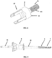
Figure 4 est une vue en perspective de l'élément postérieur selon un mode de réalisation de la présente invention. -
Figure 5 est une vue latérale du système d'implant selon un mode de réalisation de la présente invention, monté sur un instrument adapté pour l'insertion du système d'implant. -
Figure 6A est une vue latérale du système d'implant, selon un mode de réalisation de la présente invention, placé dans une vertèbre ; ladite vertèbre étant représentée transparente, visible uniquement par ses contours. -
Figure 6B est une vue de dessus du système d'implant, selon un mode de réalisation de la présente invention, placé dans une vertèbre ; ladite vertèbre étant représentée transparente, visible uniquement par ses contours. -
Figure 7A est une vue en coupe du système d'implant selon un mode de réalisation de la présente invention, avant expansion de la partie antérieure de l'implant. -
Figure 7B est une vue en coupe du système d'implant selon un mode de réalisation de la présente invention, après expansion de la partie antérieure de l'implant. -
Figure 8A est une vue en coupe du système d'implant, après expansion de la partie antérieure de l'implant illustrant les moyens de solidarisation de la fixation pédiculaire à l'implant intravertébral selon un mode de réalisation de la présente invention. -
Figure 8B est une vue en perspective de l'implant intervertébral, après expansion de la partie antérieure de l'implant illustrant les moyens de solidarisation de la fixation pédiculaire à l'implant selon un mode de réalisation de la présente invention. -
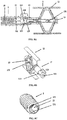
Figure 8C est une vue en perspective de la fixation pédiculaire illustrant notamment la portion interne antérieure selon un mode de réalisation de la présente invention. -
Figure 9A est une vue en coupe du système d'implant, après expansion de la partie antérieure de l'implant illustrant les moyens de solidarisation de la fixation pédiculaire à l'implant intravertébral selon un mode de réalisation de la présente invention. -
Figure 9B est une vue en perspective de l'implant, après expansion de la partie antérieure de illustrant les moyens de solidarisation de la fixation pédiculaire à l'implant intravertébral selon un mode de réalisation de la présente invention. -
Figure 10A est une vue latérale du système d'implant selon un mode de réalisation de la présente invention placé dans une vertèbre ; ladite vertèbre étant représentée transparente, visible uniquement par ses contours. -
Figure 10B est une vue en coupe du système d'implant selon un mode de réalisation de la présente invention placé dans une vertèbre ; ladite vertèbre étant représentée transparente, visible uniquement par ses contours. - Les dessins des figures ne sont pas à l'échelle. Il va de soi que la portée de l'invention ne se limite pas aux exemples de réalisation plus spécialement décrit et représentés en référence aux dessins annexés ; elle en embrasse au contraire toutes les variantes.
-
- 1 Implant intravertébral,
- 11 Partie antérieure de l'implant intravertébral,
- 12 Partie postérieure de l'implant intravertébral,
- 121 Épaulement,
- 122 Évidement cylindrique,
- 123 Chambre,
- 124 Orifice traversant,
- 125 Fente,
- 126 Taraudage interne,
- 127 Extrémité postérieure évasée,
- 128 Portion postérieure de la partie postérieure de l'implant intravertébral,
- 13 Tube de traction central,
- 131 Orifice traversant,
- 2 Fixation pédiculaire, notamment douille pédiculaire,
- 21 Filetage,
- 22 Portion interne postérieure,
- 221 Taraudage,
- 23 Portion interne antérieure,
- 231 Rainure,
- 24 Moyen d'entraînement en rotation de la fixation pédiculaire - Encoche,
- 25 Chanfrein d'entrée,
- 3 Élément postérieur, 31 Portion antérieure,
- 311 Filetage,
- 32 Portion postérieure,
- 33 Surface d'appui,
- 4 Vertèbre,
- 5 Instrument d'insertion,
- 51 Canule solidaire en rotation de la fixation pédiculaire,
- 52 Tube d'expansion,
- 6 Bouchon conique d'expansion.
- La présente invention concerne un système d'implant intravertébral expansible avec fixation pédiculaire postérieure.
- Selon un premier mode de réalisation, le système d'implant comprend un implant intravertébral associé à une fixation pédiculaire assurant un ancrage supplémentaire au niveau du pédicule vertébral.
- Selon un second mode de réalisation, comme représenté sur la
Figure 1 , le système d'implant comprend un implant intravertébral 1 associé à une fixation pédiculaire 2 et à un élément postérieur 3 permettant de connecter, postérieurement à la vertèbre, tout dispositif visant à stabiliser, renforcer ou réparer la fracture vertébrale, notamment la fracture vertébrale par compression. - Comme représenté sur la
Figure 2 , l'implant intravertébral 1 selon la présente invention comprend une partie antérieure 11 et une partie postérieure 12. - Selon un mode de réalisation, la partie antérieure 11 correspond à un implant intravertébral 1 déformable et expansible tel que l'implant SpineJack® commercialisé par la société VEXIM, connu de l'homme du métier et également décrit dans la demande de brevet
EP 1 778 136 , incorporée ici par référence. Il est précisé que l'homme du métier, à la lecture de ladite demande de brevet saurait facilement retrouver les caractéristiques nécessaires pour la réalisation de la présente invention. En particulier, la partie antérieure 11 de l'implant intravertébral 1 de la présente invention consiste en une partie expansible permettant un redressement osseux et comprenant : - un plan d'expansion unique déterminé, intrinsèque à ladite partie antérieure 11,
- un premier et un deuxième plateaux opposés, aptes à former respectivement une première et une deuxième surfaces d'appui dans un corps vertébral destinées à s'éloigner l'une de l'autre suivant ledit plan d'expansion unique lors de l'expansion de l'implant,
- un premier et un deuxième appuis pour chacun desdits premier et deuxième plateaux, situés sous ces derniers respectivement, et
- des moyens de réglage d'une valeur déterminée d'expansion, comportant un voile de matière disposé entre chaque appui et un plateau correspondant, ledit voile possédant une épaisseur déterminée qui permet de contrôler l'expansion de l'implant. Selon un mode de réalisation, ladite partie antérieure 11 comprend également un tube de traction central 13 permettant de piloter l'expansion des premiers et deuxièmes plateaux. Selon un mode de réalisation alternatif, la partie antérieure 11 de l'implant intravertébral 1 correspond à tout implant intravertébral connu de l'homme du métier qui soit déformable, expansible et apte à rester dans le corps vertébral après expansion.
- Selon un mode de réalisation, tel que représenté sur les
Figures 7A-B ,8A-B ,9A-B et10A-B , le tube de traction central 13 est creux et comprend au moins un orifice traversant 131 permettant l'injection d'un matériau de remplissage dans la vertèbre 4, tel que du ciment osseux, après expansion des premier et deuxième plateaux. Selon un mode de réalisation, le tube de traction central 13 comprend au moins 1, 2, 3, 4, 5, 6, 7, 8, 9, 10 orifices traversant 131. Selon un mode de réalisation, le(s) orifice(s) traversant 131 traverse radialement le tube de traction central 13 afin de permettre une communication fluide entre le conduit interne et la surface externe. Selon un mode de réalisation, le tube de traction central 13 comprend une pluralité d'orifices traversant 131 régulièrement répartis sur sa surface. Selon un mode de réalisation, le au moins un orifice traversant 131 se situe entre les deux plateaux afin d'être en communication fluide avec l'intérieur de la vertèbre après l'expansion de l'implant et l'écartement des deux plateaux. Avantageusement, l'injection d'un matériau de remplissage dans la vertèbre 4 permet de maintenir la partie antérieure 11 de l'implant 1 en position dans le corps vertébral après expansion. Selon un mode de réalisation, le matériau de remplissage est un ciment osseux biocompatible, par exemple un ciment ionique, un ciment phosphocalcique, un ciment acrylique ou un composé de ceux-ci, ou une résine. Selon un mode de réalisation, le matériau de remplissage se solidifie après injection. Avantageusement, la solidification du matériau de remplissage permet de consolider la vertèbre 4 et de renforcer la solidité de l'implantation du système d'implant dans la vertèbre 4. - Selon un mode de réalisation, la partie postérieure 12 est un corps cylindrique creux relié, à son extrémité antérieure, à l'extrémité postérieure de la partie antérieure 11 par un épaulement 121. Ladite partie postérieure 12 comprend un évidement cylindrique 122 au travers duquel peut coulisser un tube de traction central 13, situé initialement dans la partie antérieure 11. Par traction sur le tube de traction central 13, le tube de traction central 13 coulisse dans l'évidement cylindrique 122 de la partie postérieure 12 et les extrémités antérieures et postérieures de la partie antérieure 11 se rapproche entraînant l'expansion des premiers et deuxièmes plateaux de la partie antérieure 11 de l'implant intravertébral 1. Le tube de traction central 13 permet de piloter le déploiement de la partie antérieure déformable expansible 11. Une fois le tube de traction 13 tracté à l'intérieur de l'évidement 122, le tube ne peut plus revenir à sa position initiale, ce qui maintient l'expansion de la partie antérieure 11, en attendant l'injection de ciment ou substitut osseux.
- Selon un mode de réalisation illustré notamment par la
Figure 8B , la partie postérieure 12 de l'implant intravertébral 1 comprend un évidement cylindrique 122 et au moins un orifice traversant 124. Avantageusement le au moins un orifice traversant se situe dans la portion postérieure 128 de la partie postérieure 12. Selon un mode de réalisation, la portion postérieure 128 correspond à la portion de la partie postérieure de l'implant intravertébral 12 qui reste en permanence à l'intérieur de la portion interne antérieure 23. Selon un mode de réalisation, l'évidement cylindrique 122 traverse toute la partie postérieure de l'implant 12. Selon un mode de réalisation, la partie postérieure de l'implant intravertébral 12, et notamment la portion postérieure 128 comprend en outre une portion avec un diamètre externe réduit définissant ainsi une chambre périphérique 123. Selon un mode de réalisation, le au moins un orifice traversant 124 traverse la partie postérieure de l'implant 12 depuis l'évidement cylindrique 122 jusqu'à la chambre périphérique 123. Selon un mode de réalisation, la partie postérieure 12 de l'implant, et notamment sa portion postérieure 128 comprend au moins 1, 2, 3, 4, 5, 6, 7, 8, 9, 10 orifices traversant 124. Selon un mode de réalisation, les orifices traversant 124 sont régulièrement répartis sur la portion postérieure 128. - Selon un mode de réalisation illustré par la
Figure 9B , la partie postérieure de l'implant intravertébral 12 comprend un évidement cylindrique 122 et au moins une fente 125 traversant la partie postérieure 12 et s'étendant axialement. Avantageusement la au moins une fente 125 se situe dans la portion postérieure 128 de la partie postérieure 12. Selon un mode de réalisation, la portion postérieure 128 correspond à la portion de la partie postérieure de l'implant intravertébral 12 qui reste en permanence à l'intérieur de la portion interne antérieure 23. Selon un mode de réalisation, l'évidement cylindrique 122 traverse toute la partie postérieure de l'implant 12. Selon un mode de réalisation, la partie postérieure de l'implant intravertébral 12, et notamment la portion postérieure 128 comprend en outre un taraudage interne 126 situé sur la surface interne de l'évidement cylindrique 122. Selon un mode de réalisation, la partie postérieure de l'implant intravertébral 12, et notamment la portion postérieure 128 comprend en outre une extrémité postérieure évasée 127 pouvant coopérer avec un bouchon conique d'expansion 6. Selon un mode de réalisation, la partie postérieure 12 comprend au moins 1, 2, 3, 4, 5, 6, 7, 8, 9, 10 fentes 125. Selon un mode de réalisation, la fente 125 s'étend sur tout ou partie de la portion postérieure 128. Selon un mode de réalisation, le taraudage 126 s'étend sur tout ou partie de la portion postérieure 128. - Selon un mode de réalisation, l'expansion de l'implant intervertébral 1 n'est pas due à l'injection d'un produit dans la partie postérieure de l'implant 1. Cependant, l'injection d'un matériau de remplissage peut permettre de stabiliser l'implant une fois dans sa position en expansion. Selon un mode de réalisation, l'implant intervertébral 1 ne comprend pas une poche destinée à être emplie d'un produit (e.g. un matériau de remplissage) afin de permettre l'expansion de la poche. Selon un mode de réalisation, la seule injection d'un matériau de remplissage au travers de la partie antérieure 11 ne permet pas l'expansion de l'implant intervertébral 1.
- Selon un mode de réalisation, la partie postérieure 12 de l'implant intervertébral 1 ne comprend pas de filetage externe destiné à être vissé avec la fixation pédiculaire 2.
- Comme représentée sur la
Figure 3A , la fixation pédiculaire 2 selon la présente invention comprend au moins un filetage 21. Selon un mode de réalisation, la fixation pédiculaire 2 comprend un filetage 21 sur la surface externe de la fixation pédiculaire 2. Ledit filetage 21 externe est apte à fournir un ancrage osseux dans le pédicule. L'ancrage de la fixation pédiculaire 2 dans un pédicule vertébral offre un appui mécanique supplémentaire à l'implant intravertébral 1, et notamment à la partie antérieure expansible 11 dudit implant 1. L'insertion de la fixation pédiculaire 2 dans le tissu osseux est facilitée par un chanfrein 25 situé à l'extrémité antérieure de la fixation pédiculaire 2. Selon un mode de réalisation, la surface externe de la fixation pédiculaire 2 ne présente pas de texture autre que celle induite par un filetage, comme par exemple une structure maillée, striée ou mouchetée. Comme représentée sur laFigure 3B , la fixation pédiculaire 2 est une douille ou chemise pédiculaire cylindrique creuse comprenant une portion interne postérieure 22 et une portion interne antérieure 23. Selon un mode de réalisation, la fixation pédiculaire 2 n'est pas une vis pédiculaire pleine comprenant une portion partielle interne creuse. Selon un mode de réalisation, la fixation pédiculaire 2 est creuse sur toute sa longueur. Selon un mode de réalisation, les portions internes postérieure 22 et antérieure 23 ne présentent pas le même état de surface. - Selon un mode de réalisation, la portion interne postérieure 22 comprend un taraudage 221 ou tout autre moyen à la portée de l'homme du métier permettant de relier la fixation 2 à un élément postérieur 3.
- Selon un mode de réalisation, la portion interne antérieure 23 comprend un alésage définissant une portion creuse de réception de la partie postérieure 12 de l'implant intravertébral 1. Selon un mode de réalisation, la surface de la portion interne antérieure 23 est lisse. Selon un mode de réalisation, la surface de la portion interne antérieure 23 n'est pas taraudée. Selon un mode de réalisation, l'implant intravertébral 1, et notamment la partie postérieure 12, ne traverse pas l'intégralité de la fixation pédiculaire creuse 2. Selon un mode de réalisation, la partie postérieure 12 de l'implant intervertébral 1 est destinée à être insérée à l'intérieur de la portion interne antérieure 23. Selon un mode de réalisation, la partie postérieure 12 sert de guidage à la fixation pédiculaire 2. L'épaulement 121 sert ainsi de butée de guidage pour la fixation 2. Selon un mode de réalisation, la partie postérieure 12 de l'implant intravertébral 1 peut se déplacer selon au moins un degré de liberté, préférentiellement 2 degrés de liberté dans la portion interne antérieure 23 de la fixation pédiculaire 2. Selon un mode de réalisation, la partie postérieure 12 de l'implant intervertébral 1 est coulissante dans la portion interne antérieure 23. Selon un mode de réalisation, la liaison mécanique entre la partie postérieure 12 et la portion interne antérieure 23 est une liaison pivot glissant. Selon un mode de réalisation, la fixation pédiculaire 2, notamment la douille pédiculaire, définit un axe principal. Selon ce mode de réalisation, la partie postérieure 12 de l'implant intravertébral 1 peut se déplacer en rotation et en translation selon ledit axe principal dans la portion interne antérieure 23 de la fixation pédiculaire 2.
- Avantageusement, la portion antérieure 23 permet l'expansion de l'implant intervertébral 1 indépendamment de l'ancrage de la fixation pédiculaire 2 dans le pédicule vertébral. En effet, le degré de liberté en translation selon l'axe principal de la fixation pédiculaire 2 permet de ne pas contraindre le positionnement (i.e. l'avancement dû au déploiement) de l'implant intervertébral 1 dans le corps vertébral. De plus, le degré de liberté en rotation autour de l'axe principal de la fixation pédiculaire 2 permet de ne pas contraindre la direction d'expansion de l'implant intervertébral 1. Ainsi, l'implant intervertébral 1, lorsqu'il est déployé, adapte sa position de déploiement en fonction du milieu dans lequel il est déployé (i.e. le corps vertébral).
- Selon un mode de réalisation, la portion interne antérieure 23 ne comprend pas de filetage. Selon un mode de réalisation, la portion interne antérieure 23 et l'implant intervertébral 1 ne sont pas vissés.
- Selon un mode de réalisation, la portion interne antérieure 23 comprend en outre au moins une rainure 231, comme représenté sur la
Figure 8C . Selon un mode de réalisation, la portion interne antérieure 23 comprend au moins une rainure axiale (i. une rainure parallèle à l'axe z). Selon un mode de réalisation, la portion interne antérieure 23 comprend au moins une rainure transverse (i.e. perpendiculaire à l'axe z). Selon un mode de réalisation, la portion interne antérieure 23 comprend au moins une rainure oblique 231. Selon un mode de réalisation, la portion interne antérieure 23 comprend au moins une rainure 231 axiale et/ou transverse et/ou oblique. Selon un mode de réalisation, la au moins une rainure 231 comprend une section non constante. Selon un mode de réalisation, la portion interne antérieure 23 comprend au moins 2, 3, 4, 5, 6, 7, 8, 9, 10 rainures 231. Selon un mode de réalisation, les rainures sont régulièrement réparties sur la surface interne de la portion antérieure 12. Selon un mode de réalisation, la fixation pédiculaire 2 comprend au moins une encoche 24, ou tout autre moyen à la portée de l'homme du métier, permettant d'entraîner en rotation la fixation pédiculaire 2, à l'aide d'un instrument d'insertion 5. - Comme représenté sur la
Figure 4 , l'élément postérieur 3 selon la présente invention comprend une portion antérieure 31 constituée d'une tige, de préférence une tige filetée 311 coopérant avec le taraudage 221 de la fixation pédiculaire 2, permettant ainsi la fixation de l'élément postérieur 3 à la fixation pédiculaire 2. L'élément postérieur 3 comprend également une portion postérieure 32, externe à la vertèbre 4, dont la géométrie permet d'assurer des fonctions d'assemblage avec des éléments de fixation postérieurs complémentaires et connus de l'homme du métier comme des barres ou des ligaments artificiels. Toute autre configuration d'assemblage à d'autres systèmes connu de l'homme du métier peut être envisagée. L'élément postérieur 3 comprend également une surface d'appui 33 contre le tissu osseux ou contre la portion postérieure de la fixation pédiculaire 2, selon le choix effectué par l'opérateur et/ou l'enfoncement de la fixation pédiculaire 2 dans l'os pédiculaire. - Après la création d'une voie d'abord et l'alésage du pédicule vertébral, le système d'implant comprenant la fixation pédiculaire 2 et l'implant vertébral 1 dont la partie postérieure 12 est insérée dans la portion interne antérieure 23 de la fixation pédiculaire 2 est inséré, puis vissé, dans le pédicule l'aide d'un instrument d'insertion 5, comme représenté sur la
Figure 5 . Ledit instrument d'insertion 5 comprend une canule de travail 51 solidaire (i.e. connectée) en rotation de la fixation pédiculaire 2 par l'intermédiaire des encoches 24 permettant de visser la fixation pédiculaire 2 dans le pédicule. Ledit instrument d'insertion 5 comprend également un tube d'expansion 52 situé le long de l'axe principal de l'instrument d'insertion 5 et il est configuré pour traverser au moins la longueur de la portion interne postérieure 22. Le tube d'expansion 52 est solidaire (i.e. connecté) de la partie postérieure 12 de l'implant intravertébral 1, et notamment solidaire du tube de traction central 13 de l'implant intravertébral 1. La profondeur d'insertion du système d'implant est contrôlée par l'opérateur par le vissage du filetage 21 de la fixation pédiculaire 2 dans le tissu osseux, afin de positionner l'implant intravertébral 1 de manière optimale dans le corps vertébral. Le positionnement de l'implant intravertébral 1 en rotation axiale est contrôlé par l'opérateur de manière indépendante de l'insertion de la fixation pédiculaire 2, à l'aide du tube 52 de manière à conserver un plan d'expansion, par exemple un plan d'expansion cranio-caudal de l'implant intravertébral 1 quel que soit l'angle de vissage obtenu lors de l'insertion de la fixation pédiculaire 2. Comme représenté sur lesFigures 6A, 6B ,10A et 10B , le système d'implant intravertébral selon la présente invention est inséré à travers un pédicule vertébral, l'implant intravertébral 1 étant alors situé dans le corps vertébral et la fixation pédiculaire 2 étant ancrée dans le pédicule. - Selon un mode de réalisation, après insertion du système d'implant, la fixation pédiculaire 2 est solidement fixée dans le pédicule et l'implant intravertébral 1 est partiellement solidaire de la fixation pédiculaire 2 par sa partie postérieure cylindrique 12. En effet, la partie postérieure cylindrique 12 est insérée dans la portion interne antérieure 23 bloquant ainsi les mouvements de rotations autour des axes y et x et bloquant les translations le long desdits axes x et y. De ce fait, ces degrés de liberté bloqués assurent une solidarité partielle entre la partie postérieure cylindrique 12 insérée dans la portion interne antérieure 23. Par solidarisation on entend le blocage de tous les degrés de liberté entre la fixation pédiculaire 2 et l'implant intravertébral 1. Par solidarisation partielle, on entend, le blocage d'au moins un degré de liberté entre ces deux parties. La fixation pédiculaire 2 vient alors en butée sur l'épaulement 121. Ainsi l'implant intravertébral 1 possède un point d'appui supplémentaire dans le pédicule. Selon un mode de réalisation, l'implant vertébral 1 n'est pas solidaire de la fixation pédiculaire 2 par vissage. Selon un mode de réalisation, la partie postérieure 12 de l'implant intervertébral 1 assemblée à la fixation pédiculaire 2 ne traverse pas de part en part la fixation pédiculaire 2. Selon un mode de réalisation, la partie postérieure 12 de l'implant vertébral 1 est montée dans la portion interne antérieure 23 de la fixation pédiculaire 2.
- Comme représentée sur les
Figures 7A et 7B , l'expansion de l'implant intravertébral 1 est réalisée par traction sur le tube de traction central 13, à travers le tube 52 de l'instrument d'insertion 5 (non représenté sur les figures). Le tube de traction central 13 peut coulisser unidirectionnellement dans la partie postérieure 12 de l'implant 1 afin de permettre le déploiement tout en empêchant le retrait. La traction du tube de traction central 13 permet le déploiement de l'implant intervertébral 1 par rapprochement des extrémités antérieure et postérieure de la partie antérieure 11. Selon un mode de réalisation, le déploiement permet l'écartement des plateaux dans le corps vertébral. Cette expansion dans le corps vertébral provoque le déplacement antérieur de l'implant : la partie antérieure 11 de l'implant expansible coulisse au travers de la portion interne antérieure 23 afin que la partie antérieure 11 de l'implant intervertébrale s'adapte de manière optimale à l'environnement dans lequel elle se déploie. Avantageusement, la liaison coulissante entre la portion interne postérieure 23 de la fixation pédiculaire 2 et de la partie postérieure 12 de l'implant 1 permet l'adaptation de la position de l'implant intervertébral 1 déployé dans le corps vertébral indépendamment de la position de la fixation pédiculaire 2. - Comme représentée sur la
Figure 7B , la partie postérieure 12 peut coulisser librement dans la portion interne antérieure 23, sans toutefois en sortir afin d'assurer un appui supplémentaire permanent, de manière à ne pas contraindre le déploiement de l'implant intravertébral dans une position dépendante de la localisation de la fixation pédiculaire 2 dans le pédicule. En effet, la portion interne antérieure 23 est configurée pour bloquer les translations et les rotations de l'implant intervertébral 1 selon les axes x et y de la fixation pédiculaire 2, et permettre la translation et la rotation selon l'axe principal de la fixation pédiculaire 2 (i.e. l'axe z). - Selon un mode de réalisation, les dimensions de la partie postérieure 12 de l'implant 1 sont telles qu'une fois la partie postérieure 12 insérée dans la portion interne antérieure 23, l'implant 1 ne peut plus être extrait de la fixation pédiculaire lorsqu'il est implanté. La dimension longitudinale de la portion interne antérieure 23 est suffisamment longue pour que la partie postérieure 12 reste insérée et partiellement solidaire de ladite portion interne antérieure 23 lors du déploiement. Selon un mode de réalisation, la longueur de la portion interne antérieure 23 est en effet comprise entre 1 et 20 mm ou entre 5 et 15 mm.
- Selon ce mode de réalisation, l'implant intravertébral 1 est libre en rotation axiale et en translation antérieure par rapport à la fixation pédiculaire 2. Le déploiement de l'implant intravertébral 1 se produit ainsi uniquement en fonction de l'environnement osseux intravertébral qui impose à la partie antérieure 11 extensible de l'implant intervertébrale 1 l'orientation et la profondeur de déploiement de ladite partie extensible. Selon un mode de réalisation, l'implant intravertébral, et notamment sa partie postérieure 12, peut se déplacer selon un, deux, trois, quatre, cinq degrés de liberté, préférentiellement deux degrés de liberté, encore plus préférentiellement un degré de liberté en rotation et un degré de liberté en translation, dans la portion interne antérieure 23. Selon un mode de réalisation, l'implant intravertébral 1, et notamment sa partie postérieure 12, peut se déplacer en rotation et en translation selon l'axe z dans la portion interne antérieure 23.
- Selon un mode de réalisation, après l'expansion de l'implant intravertébral 1, la rotation et la translation suivant z entre l'implant intravertébral et la fixation pédiculaire sont bloquées, rendant ainsi solidaire l'implant intravertébral expansible 1 de la fixation pédiculaire 2.
- Selon un mode de réalisation, la partie antérieure de l'implant intravertébral 11 est stabilisée en position d'expansion par injection d'un matériau de remplissage dans la vertèbre 4, au travers du au moins un orifice traversant 131. Le matériau de remplissage est injecté au moyen d'un injecteur au travers de la fixation pédiculaire 2, de l'évidement cylindrique 122 de la partie postérieure de l'implant 12 et du tube de traction creux 13, jusqu'au niveau de la partie antérieure 11 de l'implant 1.
- Selon un mode de réalisation, la partie postérieure de l'implant intravertébral 12 est solidarisée à la fixation pédiculaire 2 en bloquant les mouvements relatifs de la portion postérieure 12 par rapport à la fixation pédiculaire 2 à l'aide de moyens de solidarisation.
- Selon un mode de réalisation, tel qu'illustré sur la
Figure 8A , la partie postérieure de l'implant intravertébral 12 est solidarisée dans la fixation pédiculaire 2 par injection d'un matériau de remplissage. Le matériau de remplissage est injecté au travers de la portion interne postérieure 22 dans l'évidement cylindrique 122 et dans le au moins un orifice traversant 124 afin d'entrer en contact avec la surface interne de la portion interne antérieur 23. Avantageusement la portion postérieure 128 comprend une chambre périphérique 123 dans laquelle débouche le au moins un orifice traversant 124. Ainsi le matériau de remplissage rempli le au moins un orifice traversant 124 et la chambre périphérique 123 afin de répartir le matériau de remplissage à l'interface entre la portion postérieure 128 et la portion interne antérieure 23 et ainsi augmenter la surface de contact. Afin de renforcer encore la solidarisation, la portion interne antérieure 23 comprend au moins une rainure 231 et le matériau de remplissage injecté dans l'évidement cylindrique 122 rempli le au moins un orifice traversant 124, la chambre périphérique 123 et la au moins une rainure 231 de la portion interne antérieure 23. Avantageusement, la solidification du matériau de remplissage dans la au moins rainure 231 axiale renforce la solidarisation selon le degré de liberté en rotation autour de l'axe z. Avantageusement, la solidification du matériau de remplissage dans la au moins rainure 231 transverse renforce la solidarisation selon le degré de liberté en translation suivant l'axe z. Avantageusement, la solidification du matériau de remplissage dans la au moins rainure 231 oblique renforce la solidarisation selon les degrés de liberté en translation et en rotation suivant l'axe z. Avantageusement, la solidification du matériau de remplissage dans la au moins une rainure 231 de section non constante renforce la solidarisation selon le degré de liberté en translation et en rotation suivant l'axe z. Selon un mode de réalisation, les rainures 231 permettent en outre l'injection du matériau de remplissage jusque dans la potion interne antérieure 23 renforçant davantage la solidarisation. Selon un mode de réalisation, le matériau de remplissage injecté dans l'évidement cylindrique 122 rempli le au moins un orifice traversant 124, la chambre périphérique 123 et la au moins une rainure 231 de la portion interne antérieure 23, et tout ou partie du volume de la portion interne antérieure 23. Avantageusement, la chambre périphérique 123 permet d'atteindre les rainures 231 indépendamment de l'orientation de l'implant intervertébral 1, et notamment de l'orientation de la portion postérieure 128, dans la fixation pédiculaire 2. - Selon un mode de réalisation, tel qu'illustré sur la
Figure 9A , la partie postérieure de l'implant intravertébral 12 est solidarisée dans la fixation pédiculaire 2 par l'intermédiaire d'un bouchon conique d'expansion 6. Ledit bouchon conique comprend un filetage externe et une extrémité postérieure évasée. Ledit bouchon 6 est inséré au travers de la portion interne postérieure 22, optionnellement après injection de ciment dans la vertèbre par l'intermédiaire de l'orifice traversant 131, et visé dans le taraudage 126 de la portion postérieure 128. Lors du vissage du bouchon conique 6 dans le taraudage 126 de la portion postérieure 128, l'extrémité évasée du bouchon butte contre l'extrémité évasée de la portion postérieure 127 entraînant le déploiement radiale de la portion postérieur, rendu possible grâce aux fentes 125. Avantageusement, le déploiement radial de la portion postérieure 128 dans la portion interne antérieure 23 solidarise la partie postérieure de l'implant intravertébral 12 dans la fixation pédiculaire 2 par appui. - Selon un mode de réalisation, une fois l'implant intravertébral 1 déployé, solidarisé à la fixation pédiculaire 2 et stabilisé, si besoin au moyen de l'injection de ciment ou de substitut osseux spécialement adapté, il est alors possible de solidariser (i.e. connecter) à l'ensemble fixation pédiculaire 2 - implant intravertébral 1 l'élément postérieur 3 par simple vissage et serrage de ce dernier dans la portion interne postérieure 22 de la fixation pédiculaire 2. Dans ce mode de réalisation, l'élément postérieur 3 est au moins partiellement extérieur à la vertèbre 4 et est alors capable de recevoir des éléments postérieurs de fixation tels que des barres ou systèmes de ligaments artificiels ou tout autre moyen de stabilisation de la fracture vertébrale connu de l'homme du métier.
- La présente invention concerne également une méthode de traitement de fractures vertébrales comprenant :
- l'insertion d'un système d'implant selon l'invention dont la partie postérieure 12 est déjà insérée dans la portion interne antérieure 23 dans une vertèbre 4 et le vissage de la fixation pédiculaire 2 dans le pédicule vertébrale par l'intermédiaire du filetage externe 21 ;
- l'expansion de la partie antérieure 11 de l'implant intravertébral 1, notamment par traction du tube de traction centrale 13 ;
- le positionnement de la partie antérieure 11 de l'implant intravertébral dans le corps vertébral rendu possible par le déplacement de la partie postérieure 12 de l'implant intravertébral 1 en translation et en rotation, selon l'axe principal de la fixation pédiculaire 2, dans la portion interne antérieure 23 de la fixation pédiculaire 2 ; optionnellement, l'injection d'un matériau de remplissage dans le corps vertébral par l'intermédiaire d'un orifice traversant 131 pour stabiliser la partie antérieure de l'implant intravertébral 11 ; et
- optionnellement, la solidarisation de la partie postérieure 12 dans la portion interne antérieure 23.
-
- 1. Système d'implant intravertébral expansible comprenant un implant intravertébral (1) comprenant une partie antérieure (11) expansible dans un corps vertébral et une partie postérieure (12); et une fixation pédiculaire (2) comprenant une portion interne postérieure (22) et une portion interne antérieure (23) définissant une portion creuse de réception de la partie postérieure (12), dans laquelle la partie postérieure (12) de l'implant intravertébral (1) peut se déplacer selon au moins un degré de liberté.
- 2. Système d'implant intravertébral expansible selon le mode 1, dans lequel la fixation pédiculaire (2) comprend un filetage (21) assurant l'ancrage de ladite fixation pédiculaire dans un pédicule vertébral.
- 3. Système d'implant intravertébral expansible selon le mode 1 ou le mode 2, dans lequel la fixation pédiculaire (2) comprend un axe principal et la partie postérieure (12) de l'implant intravertébral (1) peut se déplacer en translation et en rotation, selon l'axe principal de la fixation pédiculaire (2), dans la portion interne antérieure (23) de la fixation pédiculaire (2); de manière à ce que la direction d'expansion de la partie antérieure (11) de l'implant intravertébral (1) soit indépendante de la position de la fixation pédiculaire (2) dans le pédicule vertébral.
- 4. Système d'implant intravertébral expansible selon l'un quelconque des modes 1 à 3, dans lequel la partie antérieure (11) de l'implant intravertébral (1) comprend un premier et un deuxième plateaux, aptes à former respectivement une première et une deuxième surfaces d'appui dans un corps vertébral ; ces deux surfaces d'appui étant appelées à s'éloigner l'une dans l'autre suivant un plan d'expansion prédéfini.
- 5. Système d'implant intravertébral expansible selon l'un quelconque des modes 1 à 4, dans lequel la portion interne antérieure (23) comprend au moins une rainure (231) sur sa surface interne.
- 6. Système d'implant intravertébral expansible selon l'un quelconque des modes 1 à 5, dans lequel une portion postérieure (128) de la partie postérieure de l'implant intravertébral (12) comprend un évidement cylindrique (122) et au moins un moyen de solidarisation permettant de bloquer en rotation et en translation les mouvements relatifs entre l'implant intervertébral (1) et la fixation pédiculaire (2).
- 7. Système d'implant intravertébral expansible selon le mode 6, dans lequel le moyen de solidarisation comprend au moins un orifice traversant (124), traversant la portion postérieure (128), et une chambre périphérique (123) à la surface de la portion postérieure (128) en communication fluide avec le au moins un orifice traversant (124).
- 8. Système d'implant intravertébral expansible selon le mode 6, dans lequel le moyen de solidarisation comprend au moins deux fentes (125) s'étendant axialement le long de la portion postérieure (128), un taraudage interne (126) et une extrémité postérieure évasée (127) ; pouvant coopérer avec un bouchon conique d'expansion (6).
- 9. Système d'implant intravertébral expansible selon l'un quelconque des modes 1 à 8, comprenant en outre un élément postérieur (3), partiellement extérieur à la vertèbre et solidaire de la fixation pédiculaire (2).
- 10.Système d'implant intravertébral expansible selon le mode 9, dans lequel l'élément postérieur (3) est solidaire de la fixation pédiculaire (2) par l'intermédiaire d'une tige filetée (311) vissée dans un taraudage (221) de la portion interne postérieure (22).
- 11.Système d'implant intravertébral expansible selon l'un quelconque des modes 9 ou 10, dans lequel l'élément postérieur (3) comprend une portion postérieure (32) permettant l'assemblage avec des éléments de fixation postérieurs complémentaires tels que des barres ou des ligaments artificiels.
Claims (13)
- Système d'implant intravertébral expansible comprenant:un implant intravertébral (1) comprenant :une partie postérieure (12), etune partie antérieure (11) expansible configurée pour placement dans un corps vertébral, et comprenant un premier et un deuxième plateaux, aptes à former respectivement une première et une deuxième surfaces d'appui dans le corps vertébral ; etune fixation pédiculaire (2) comprenant une portion interne postérieure (22) et une portion interne antérieure (23) définissant une portion creuse de réception de la partie postérieure (12) du implant intravertébral (1) ;charactérisée en ce que la partie postérieure (12) de l'implant intravertébral (1) peut se déplacer selon au moins un degré de liberté relative à la fixation pédiculaire (2), et en ce que les deux surfaces d'appui étant appelées à s'éloigner l'une dans l'autre suivant un plan d'expansion prédéfini.
- Système d'implant intravertébral expansible selon la revendication 1, dans lequel la fixation pédiculaire (2) comprend un filetage (21) assurant l'ancrage de ladite fixation pédiculaire dans un pédicule vertébral.
- Système d'implant intravertébral expansible selon l'une quelconque des modes 1 à 2, dans lequel la portion interne antérieure (23) comprend au moins une rainure (231) sur sa surface interne.
- Système d'implant intravertébral expansible selon l'une quelconque des revendications 1 à 3, dans lequel une portion postérieure (128) de la partie postérieure de l'implant intravertébral (12) comprend un évidement cylindrique (122) et au moins un moyen de solidarisation permettant de bloquer en rotation et en translation les mouvements relatifs entre l'implant intervertébral (1) et la fixation pédiculaire (2).
- Système d'implant intravertébral expansible selon l'une quelconque des revendications 1 à 4, comprenant en outre un élément postérieur (3), partiellement extérieur à la vertèbre et solidaire de la fixation pédiculaire (2).
- Système d'implant intravertébral expansible selon la revendication 5, dans lequel l'élément postérieur (3) est solidaire de la fixation pédiculaire (2) par l'intermédiaire d'une tige filetée (311) vissée dans un taraudage (221) de la portion interne postérieure (22).
- Système d'implant intravertébral expansible selon l'une quelconque des revendications 5 ou 6, dans lequel l'élément postérieur (3) comprend une portion postérieure (32) permettant l'assemblage avec des éléments de fixation postérieurs complémentaires tels que des barres ou des ligaments artificiels.
- Système d'implant intravertébral expansible selon l'une quelconque des revendications 1 à 7, dans lequel la partie postérieure (12) de l'implant intervertébral (1) est coulissante dans la portion interne antérieure (23) et, optionnellement, dans lequel cette liaison coulissante permet l'adaptation de la position de l'implant intravertébral (1) déployé dans le corps vertébral (30) indépendamment de la position de la fixation pédiculaire (2).
- Système d'implant intravertébral expansible selon l'une quelconque des revendications 1 à 8, dans lequel la partie postérieure (12) comprend un épaulement (121) que sert de butée de guidage pour la fixation pédiculaire (2).
- Système d'implant intravertébral expansible selon l'une quelconque des revendications 1 à 9, dans lequel la fixation pédiculaire (2) comprend un chanfrein (25) situé a l'extrémité antérieure de la fixation pédiculaire (2) pour faciliter l'insertion de la fixation pédiculaire (2) dans le corps vertébral.
- Système d'implant intravertébral expansible selon l'une quelconque des revendications 1 à 10, dans lequel la portion interne antérieure (23) ne comprend pas de filetage.
- Système d'implant intravertébral expansible selon l'une quelconque des revendications 1 à 11, dans lequel la partie postérieure (12) peut coulisser librement dans la portion interne antérieure (23).
- Système d'implant intravertébral expansible selon l'une quelconque des revendications 1 à 12, dans lequel la fixation pédiculaire (2) comprend au moins une encoche (24) permettant d'entraîner en rotation la fixation pédiculaire (2) a l'aide d'un instrument d'insertion (5).
Applications Claiming Priority (3)
| Application Number | Priority Date | Filing Date | Title |
|---|---|---|---|
| FR1363467A FR3015221B1 (fr) | 2013-12-23 | 2013-12-23 | Systeme d'implant intravertebral expansible avec fixation pediculaire posterieure |
| PCT/FR2014/053549 WO2015097416A1 (fr) | 2013-12-23 | 2014-12-23 | Système d'implant intravertébral expansible avec fixation pédiculaire postérieure |
| EP14831026.1A EP3086729B1 (fr) | 2013-12-23 | 2014-12-23 | Système d'implant intravertébral expansible avec fixation pédiculaire postérieure |
Related Parent Applications (1)
| Application Number | Title | Priority Date | Filing Date |
|---|---|---|---|
| EP14831026.1A Division EP3086729B1 (fr) | 2013-12-23 | 2014-12-23 | Système d'implant intravertébral expansible avec fixation pédiculaire postérieure |
Publications (2)
| Publication Number | Publication Date |
|---|---|
| EP3838202A1 true EP3838202A1 (fr) | 2021-06-23 |
| EP3838202B1 EP3838202B1 (fr) | 2024-06-19 |
Family
ID=50829004
Family Applications (2)
| Application Number | Title | Priority Date | Filing Date |
|---|---|---|---|
| EP14831026.1A Active EP3086729B1 (fr) | 2013-12-23 | 2014-12-23 | Système d'implant intravertébral expansible avec fixation pédiculaire postérieure |
| EP21156698.9A Active EP3838202B1 (fr) | 2013-12-23 | 2014-12-23 | Système d'implant intravertébral expansible avec fixation pédiculaire postérieure |
Family Applications Before (1)
| Application Number | Title | Priority Date | Filing Date |
|---|---|---|---|
| EP14831026.1A Active EP3086729B1 (fr) | 2013-12-23 | 2014-12-23 | Système d'implant intravertébral expansible avec fixation pédiculaire postérieure |
Country Status (11)
| Country | Link |
|---|---|
| US (3) | US10603080B2 (fr) |
| EP (2) | EP3086729B1 (fr) |
| JP (1) | JP2017500999A (fr) |
| KR (1) | KR102112902B1 (fr) |
| CN (1) | CN105934211B (fr) |
| BR (1) | BR112016014802B1 (fr) |
| ES (1) | ES2863556T3 (fr) |
| FR (1) | FR3015221B1 (fr) |
| MX (1) | MX395517B (fr) |
| RU (1) | RU2016130357A (fr) |
| WO (1) | WO2015097416A1 (fr) |
Cited By (2)
| Publication number | Priority date | Publication date | Assignee | Title |
|---|---|---|---|---|
| EP4717210A1 (fr) * | 2024-09-25 | 2026-04-01 | In Life Vet Sa | Implant osseux expansible de chirurgie orthopédique vétérinaire, système orthopédique et procédé de fabrication de l'implant |
| EP4717206A1 (fr) * | 2024-09-25 | 2026-04-01 | Lock-In VCF SA | Implant osseux expansible de chirurgie orthopédique humaine, système orthopédique et procédé de fabrication de l'implant |
Families Citing this family (33)
| Publication number | Priority date | Publication date | Assignee | Title |
|---|---|---|---|---|
| US20220304814A1 (en) * | 2010-07-27 | 2022-09-29 | Tenon Medical, Inc. | Prostheses for Stabilizing Bone Structures |
| US9788971B1 (en) | 2013-05-22 | 2017-10-17 | Nuvasive, Inc. | Expandable fusion implant and related methods |
| FR3015221B1 (fr) | 2013-12-23 | 2017-09-01 | Vexim | Systeme d'implant intravertebral expansible avec fixation pediculaire posterieure |
| US9907593B2 (en) | 2014-08-05 | 2018-03-06 | Woven Orthopedic Technologies, Llc | Woven retention devices, systems and methods |
| WO2016183382A1 (fr) | 2015-05-12 | 2016-11-17 | Nuvasive, Inc. | Implants intervertébraux de lordose extensibles |
| EP3331459A4 (fr) | 2015-08-05 | 2019-08-14 | Woven Orthopedic Technologies, LLC | Dispositifs, systèmes et procédés de prélèvement à utiliser dans un tissu osseux |
| US10973650B2 (en) | 2015-12-30 | 2021-04-13 | Nuvasive, Inc. | Lordotic expandable fusion implant |
| CN106420028A (zh) * | 2016-11-24 | 2017-02-22 | 常州好利医疗科技有限公司 | 椎体复位成型器 |
| EP3551105A4 (fr) | 2016-12-09 | 2020-07-29 | Woven Orthopedic Technologies, LLC | Dispositifs de retenue, treillis et systèmes et procédés associés |
| CN107115140B (zh) * | 2017-05-23 | 2024-01-02 | 温州医科大学附属第二医院温州医科大学附属育英儿童医院 | 一种用于脊柱加强椎弓根螺钉内固定装置 |
| US10172656B1 (en) | 2017-09-15 | 2019-01-08 | Alphatec Spine, Inc. | Surgical screw |
| EP3727207B1 (fr) | 2017-12-18 | 2024-04-17 | Nuvasive, Inc. | Dispositif implantable expansible |
| CN108125710B (zh) * | 2018-01-24 | 2023-11-24 | 艾科美医疗器械(深圳)有限公司 | 一种带囊袋的椎弓根钉结构 |
| NL2021874B1 (en) | 2018-10-25 | 2020-05-13 | Am Solutions Holding B V | Implants, assemblies and methods of manufacturing such implants or assemblies |
| US11344425B2 (en) | 2019-03-22 | 2022-05-31 | Nimesis Technology | Vertebral spacer |
| AU2020270775B2 (en) | 2019-04-11 | 2025-08-21 | Am Solutions Holding B.V. | Implantable expandable bone support device |
| JP7011076B2 (ja) | 2019-08-20 | 2022-01-26 | 董謝平 | 分割型動的・静的両用椎弓根スクリュー及びその取付ツール |
| US11540926B2 (en) | 2019-11-01 | 2023-01-03 | Stryker European Operations Limited | Implant for restoring height of a vertebral body |
| NL2026145B1 (en) | 2020-07-27 | 2022-03-29 | Am Solutions Holding B V | Expandable implant, implant system, kit of parts for assembling an expandable implant, and method of placing an implant in a bone |
| WO2023122005A1 (fr) | 2021-12-20 | 2023-06-29 | Stryker Corporation | Dispositif comprenant un implant expansible et des éléments d'ancrage pour ancrer le dispositif à l'intérieur d'un pédicule vertébral |
| WO2024211754A1 (fr) * | 2023-04-07 | 2024-10-10 | Texas Scottish Rite Hospital For Children | Outil et procédé de remodelage osseux |
| CN119498942A (zh) * | 2023-08-22 | 2025-02-25 | 武汉联影智融医疗科技有限公司 | 椎体撑开装置及椎体撑开操作装置 |
| CN119498904A (zh) * | 2023-08-25 | 2025-02-25 | 武汉联影智融医疗科技有限公司 | 椎体撑开装置 |
| EP4717205A1 (fr) | 2024-09-25 | 2026-04-01 | Lock-In VCF SA | Implant osseux expansible de chirurgie orthopédique humaine, système orthopédique et procédé de fabrication de l'implant |
| EP4717201A1 (fr) | 2024-09-25 | 2026-04-01 | In Life Vet Sa | Implant osseux expansible de chirurgie orthopédique vétérinaire, système orthopédique et procédé de fabrication de l'implant |
| EP4717200A1 (fr) | 2024-09-25 | 2026-04-01 | In Life Vet Sa | Implant osseux expansible, système orthopédique et procédé de fabrication de l'implant |
| EP4717207A1 (fr) | 2024-09-25 | 2026-04-01 | Lock-In VCF SA | Instruments de chirurgie orthopédique humaine d'installation d'implants osseux expansibles |
| EP4717212A1 (fr) | 2024-09-25 | 2026-04-01 | In Life Vet Sa | Implant osseux expansible de chirurgie orthopédique vétérinaire, système orthopédique et procédé de fabrication de l'implant |
| EP4717198A1 (fr) | 2024-09-25 | 2026-04-01 | Lock-In VCF SA | Implant osseux expansible de chirurgie orthopédique humaine, système orthopédique et procédé de fabrication de l'implant |
| EP4717211A1 (fr) | 2024-09-25 | 2026-04-01 | In Life Vet Sa | Implant osseux expansible de chirurgie orthopédique vétérinaire, système orthopédique et instrument associé |
| EP4717199A1 (fr) * | 2024-09-25 | 2026-04-01 | Lock-In VCF SA | Implant osseux expansible de chirurgie orthopédique humaine et système orthopédique |
| EP4717208A1 (fr) | 2024-09-25 | 2026-04-01 | Lock-In VCF SA | Implant osseux expansible de chirurgie orthopédique et système orthopédique |
| EP4717209A1 (fr) | 2024-09-25 | 2026-04-01 | In Life Vet Sa | Implant osseux expansible de chirurgie orthopédique vétérinaire, système orthopédique et procédé de fabrication de l'implant |
Citations (7)
| Publication number | Priority date | Publication date | Assignee | Title |
|---|---|---|---|---|
| US5209753A (en) | 1989-11-03 | 1993-05-11 | Lutz Biedermann | Bone screw |
| WO2005120400A2 (fr) | 2004-06-09 | 2005-12-22 | Vexim | Procedes et dispositif pour la restauration osseuse |
| US7291150B2 (en) * | 1999-12-01 | 2007-11-06 | Sdgi Holdings, Inc. | Intervertebral stabilising device |
| US20090005821A1 (en) | 2007-06-29 | 2009-01-01 | Spineworks Medical, Inc. | Methods and devices for stabilizing bone compatible for use with bone screws |
| EP2074956A1 (fr) | 2007-12-28 | 2009-07-01 | BIEDERMANN MOTECH GmbH | Implant pour la stabilisation des vertèbres |
| US20100324607A1 (en) * | 2009-06-23 | 2010-12-23 | Davis Reginald J | Pedicle screw with expansion anchor sleeve |
| US20120123481A1 (en) * | 2010-11-15 | 2012-05-17 | Lin Chih I | Bone fixation device |
Family Cites Families (205)
| Publication number | Priority date | Publication date | Assignee | Title |
|---|---|---|---|---|
| US4796612A (en) | 1986-08-06 | 1989-01-10 | Reese Hewitt W | Bone clamp and method |
| JPS6254313A (ja) | 1986-08-29 | 1987-03-10 | Toshiba Corp | 定電圧回路 |
| CA1333209C (fr) | 1988-06-28 | 1994-11-29 | Gary Karlin Michelson | Implants artificiels pour la soudure osseuse intervertebrale |
| US5451204A (en) | 1988-07-22 | 1995-09-19 | Yoon; Inbae | Multifunctional devices for endoscopic surgical procedures |
| US4961740B1 (en) | 1988-10-17 | 1997-01-14 | Surgical Dynamics Inc | V-thread fusion cage and method of fusing a bone joint |
| US4969888A (en) | 1989-02-09 | 1990-11-13 | Arie Scholten | Surgical protocol for fixation of osteoporotic bone using inflatable device |
| US4932975A (en) | 1989-10-16 | 1990-06-12 | Vanderbilt University | Vertebral prosthesis |
| US5059193A (en) | 1989-11-20 | 1991-10-22 | Spine-Tech, Inc. | Expandable spinal implant and surgical method |
| US5454365A (en) * | 1990-11-05 | 1995-10-03 | Bonutti; Peter M. | Mechanically expandable arthroscopic retractors |
| DE4021153A1 (de) * | 1990-07-03 | 1992-01-16 | Wolf Gmbh Richard | Organmanipulator |
| DE69209494T2 (de) | 1991-02-22 | 1996-10-31 | Pisharodi Madhavan | Implantat aus einer expandierbaren zwischenwirbelscheibe |
| ES2041221B1 (es) | 1992-04-24 | 1994-05-16 | Alacreu Jose Vicente Barbera | Procedimiento para la substitucion vertebral protesica en la cirugia de los tumores malignos y protesis para la practica de dicho procedimiento. |
| RU2070006C1 (ru) | 1993-03-29 | 1996-12-10 | Российский научно-исследовательский нейрохирургический институт им.проф.А.Л.Поленова | Межпозвонковый дистрактор |
| KR100318703B1 (ko) | 1993-06-10 | 2002-11-13 | 카린 테크놀러지 인코포레이티드 | 척추임플란트를 삽입하는 척주 디스트랙터 |
| US5545209A (en) | 1993-09-30 | 1996-08-13 | Texas Petrodet, Inc. | Controlled deployment of a medical device |
| RU2147213C1 (ru) | 1994-01-26 | 2000-04-10 | А. Рейли Марк | Усовершенствованное наполняемое устройство для использования в хирургическом протоколе применительно к фиксации кости |
| US7044954B2 (en) | 1994-01-26 | 2006-05-16 | Kyphon Inc. | Method for treating a vertebral body |
| US20030032963A1 (en) | 2001-10-24 | 2003-02-13 | Kyphon Inc. | Devices and methods using an expandable body with internal restraint for compressing cancellous bone |
| US6248110B1 (en) | 1994-01-26 | 2001-06-19 | Kyphon, Inc. | Systems and methods for treating fractured or diseased bone using expandable bodies |
| US6716216B1 (en) | 1998-08-14 | 2004-04-06 | Kyphon Inc. | Systems and methods for treating vertebral bodies |
| DE4415960A1 (de) | 1994-05-06 | 1995-11-09 | Schaeffler Waelzlager Kg | Transportsicherung bei einem Kettenspanner |
| US5980522A (en) | 1994-07-22 | 1999-11-09 | Koros; Tibor | Expandable spinal implants |
| DE69507333T2 (de) | 1994-11-16 | 1999-09-02 | Soubeiran | Vorrichtung zum verschieben zweier körper zueinander |
| US5665122A (en) | 1995-01-31 | 1997-09-09 | Kambin; Parviz | Expandable intervertebral cage and surgical method |
| AU705930B2 (en) | 1995-03-27 | 1999-06-03 | Warsaw Orthopedic, Inc. | Interbody fusion device and method for restoration of normal spinal anatomy |
| US5713907A (en) | 1995-07-20 | 1998-02-03 | Endotex Interventional Systems, Inc. | Apparatus and method for dilating a lumen and for inserting an intraluminal graft |
| US5800500A (en) | 1995-08-18 | 1998-09-01 | Pi Medical Corporation | Cochlear implant with shape memory material and method for implanting the same |
| US5824040A (en) | 1995-12-01 | 1998-10-20 | Medtronic, Inc. | Endoluminal prostheses and therapies for highly variable body lumens |
| US5800550A (en) | 1996-03-13 | 1998-09-01 | Sertich; Mario M. | Interbody fusion cage |
| CA2199462C (fr) | 1996-03-14 | 2006-01-03 | Charles J. Winslow | Methode et instruments pour proceder a l'insertion d'un implant |
| CA2213015A1 (fr) | 1996-08-23 | 1998-02-23 | Arterial Vascular Engineering, Inc. | Extenseur profile et procede de fabrication |
| US6190414B1 (en) | 1996-10-31 | 2001-02-20 | Surgical Dynamics Inc. | Apparatus for fusion of adjacent bone structures |
| US5695515A (en) | 1996-12-26 | 1997-12-09 | Orejola; Wilmo C. | Mitral valve dilator |
| US7959652B2 (en) | 2005-04-18 | 2011-06-14 | Kyphon Sarl | Interspinous process implant having deployable wings and method of implantation |
| US5749916A (en) | 1997-01-21 | 1998-05-12 | Spinal Innovations | Fusion implant |
| DE69840774D1 (de) | 1997-02-06 | 2009-06-04 | Howmedica Osteonics Corp | Erweiterbare, gewindelose vorrichtung zur wirbelsäulenfusion |
| US6039761A (en) | 1997-02-12 | 2000-03-21 | Li Medical Technologies, Inc. | Intervertebral spacer and tool and method for emplacement thereof |
| WO2001054598A1 (fr) | 1998-03-06 | 2001-08-02 | Disc-O-Tech Medical Technologies, Ltd. | Implants osseux expansibles |
| ES2302349T3 (es) | 1997-03-07 | 2008-07-01 | Disc-O-Tech Medical Technologies, Ltd. | Sistemas para la estabilizacion, fijacion y reparacion osea y vertebral percutaneas. |
| IL128261A0 (en) | 1999-01-27 | 1999-11-30 | Disc O Tech Medical Tech Ltd | Expandable element |
| US5972015A (en) | 1997-08-15 | 1999-10-26 | Kyphon Inc. | Expandable, asymetric structures for deployment in interior body regions |
| AU8386798A (en) | 1997-07-09 | 1999-02-08 | Tegementa, L.L.C. | Interbody device and method for treatment of osteoporotic vertebral collapse |
| JP4158339B2 (ja) | 1997-10-27 | 2008-10-01 | メドトロニック スパイン エルエルシー | 背骨用伸延インプラント |
| DE19807236C2 (de) | 1998-02-20 | 2000-06-21 | Biedermann Motech Gmbh | Zwischenwirbelimplantat |
| US6664897B2 (en) | 1998-03-09 | 2003-12-16 | William R. Pape | Method and system for livestock data collection and management |
| US6197033B1 (en) | 1998-04-09 | 2001-03-06 | Sdgi Holdings, Inc. | Guide sleeve for offset vertebrae |
| US6719773B1 (en) | 1998-06-01 | 2004-04-13 | Kyphon Inc. | Expandable structures for deployment in interior body regions |
| AU756969B2 (en) | 1998-06-01 | 2003-01-30 | Kyphon Sarl | Expandable preformed structures for deployment in interior body regions |
| US6126689A (en) | 1998-06-15 | 2000-10-03 | Expanding Concepts, L.L.C. | Collapsible and expandable interbody fusion device |
| US6146387A (en) | 1998-08-26 | 2000-11-14 | Linvatec Corporation | Cannulated tissue anchor system |
| FR2782632B1 (fr) | 1998-08-28 | 2000-12-29 | Materiel Orthopedique En Abreg | Cage de fusion intersomatique expansible |
| US6554833B2 (en) | 1998-10-26 | 2003-04-29 | Expanding Orthopedics, Inc. | Expandable orthopedic device |
| US6261289B1 (en) | 1998-10-26 | 2001-07-17 | Mark Levy | Expandable orthopedic device |
| US6193757B1 (en) | 1998-10-29 | 2001-02-27 | Sdgi Holdings, Inc. | Expandable intervertebral spacers |
| US7044134B2 (en) | 1999-11-08 | 2006-05-16 | Ev3 Sunnyvale, Inc | Method of implanting a device in the left atrial appendage |
| ES2228165T3 (es) | 1998-12-09 | 2005-04-01 | Cook Incorporated | Aguja hueca, curvada, superelastica, para uso medico. |
| US6183517B1 (en) | 1998-12-16 | 2001-02-06 | Loubert Suddaby | Expandable intervertebral fusion implant and applicator |
| US6102950A (en) | 1999-01-19 | 2000-08-15 | Vaccaro; Alex | Intervertebral body fusion device |
| US7621950B1 (en) | 1999-01-27 | 2009-11-24 | Kyphon Sarl | Expandable intervertebral spacer |
| DE29901611U1 (de) | 1999-01-30 | 1999-04-22 | Aesculap AG & Co. KG, 78532 Tuttlingen | Chirurgisches Instrument zum Einführen von Zwischenwirbelimplantaten |
| WO2000049978A1 (fr) | 1999-02-22 | 2000-08-31 | Guagliano Peter A | Procede de traitement de disque intervertebral |
| US6214050B1 (en) | 1999-05-11 | 2001-04-10 | Donald R. Huene | Expandable implant for inter-bone stabilization and adapted to extrude osteogenic material, and a method of stabilizing bones while extruding osteogenic material |
| US6419705B1 (en) | 1999-06-23 | 2002-07-16 | Sulzer Spine-Tech Inc. | Expandable fusion device and method |
| AU5701200A (en) | 1999-07-02 | 2001-01-22 | Petrus Besselink | Reinforced expandable cage |
| FR2796268B1 (fr) | 1999-07-13 | 2001-09-14 | Frederic Fortin | Dispositif de maintien d'une ossature permettant de recevoir un produit de maintien et de comblement sans risque d'epandage de ce dernier a l'interieur du corps humain |
| JP2001173863A (ja) | 1999-12-22 | 2001-06-29 | Osaka Gas Co Ltd | フレキシブルチューブ用ワンタッチ継手 |
| US6575979B1 (en) | 2000-02-16 | 2003-06-10 | Axiamed, Inc. | Method and apparatus for providing posterior or anterior trans-sacral access to spinal vertebrae |
| US6740093B2 (en) | 2000-02-28 | 2004-05-25 | Stephen Hochschuler | Method and apparatus for treating a vertebral body |
| US6332895B1 (en) | 2000-03-08 | 2001-12-25 | Loubert Suddaby | Expandable intervertebral fusion implant having improved stability |
| KR100717224B1 (ko) | 2000-04-05 | 2007-05-11 | 키폰 인크. | 골절되거나 병든 뼈를 치료하는 방법 및 장치 |
| JP2003529438A (ja) | 2000-04-07 | 2003-10-07 | カイフォン インコーポレイテッド | 挿入デバイスおよびその使用方法 |
| US6749595B1 (en) | 2000-06-15 | 2004-06-15 | Kieran P. J. Murphy | Cement delivery needle |
| US20080086133A1 (en) | 2003-05-16 | 2008-04-10 | Spineology | Expandable porous mesh bag device and methods of use for reduction, filling, fixation and supporting of bone |
| US20020068974A1 (en) | 2000-07-21 | 2002-06-06 | Kuslich Stephen D. | Expandable porous mesh bag device and methods of use for reduction, filling, fixation and supporting of bone |
| WO2002013700A2 (fr) | 2000-08-11 | 2002-02-21 | Sdgi Holdings, Inc. | Instrumentation chirurgicale et procede de traitement du rachis |
| US7114501B2 (en) | 2000-08-14 | 2006-10-03 | Spine Wave, Inc. | Transverse cavity device and method |
| WO2002030338A1 (fr) | 2000-10-10 | 2002-04-18 | Vertx, Inc. | Procédé et appareil permettant de traiter un corps vertébral |
| DE20017962U1 (de) | 2000-10-20 | 2001-01-04 | Aesculap AG & Co. KG, 78532 Tuttlingen | Wirbelersatzkörper |
| DE60140558D1 (de) | 2000-10-25 | 2009-12-31 | Kyphon S A R L | Systeme zur reposition von gebrochenen knochen mittels einer kanüle zur reponierung von knochenfrakturen |
| US6666891B2 (en) | 2000-11-13 | 2003-12-23 | Frank H. Boehm, Jr. | Device and method for lumbar interbody fusion |
| US6454807B1 (en) | 2000-11-30 | 2002-09-24 | Roger P. Jackson | Articulated expandable spinal fusion cage system |
| US6929647B2 (en) | 2001-02-21 | 2005-08-16 | Howmedica Osteonics Corp. | Instrumentation and method for implant insertion |
| US6595998B2 (en) | 2001-03-08 | 2003-07-22 | Spinewave, Inc. | Tissue distraction device |
| US7128760B2 (en) | 2001-03-27 | 2006-10-31 | Warsaw Orthopedic, Inc. | Radially expanding interbody spinal fusion implants, instrumentation, and methods of insertion |
| US6632235B2 (en) | 2001-04-19 | 2003-10-14 | Synthes (U.S.A.) | Inflatable device and method for reducing fractures in bone and in treating the spine |
| NL1018438C1 (nl) | 2001-07-02 | 2003-01-08 | Baat Medical Engineering B V | In- en uitklapbaar gereedschap voor plaatsing in een ruggenwervel. |
| US6648917B2 (en) | 2001-10-17 | 2003-11-18 | Medicinelodge, Inc. | Adjustable bone fusion implant and method |
| DE10154163A1 (de) | 2001-11-03 | 2003-05-22 | Advanced Med Tech | Vorrichtung zum Aufrichten und Stabilisieren der Wirbelsäule |
| US20030171812A1 (en) | 2001-12-31 | 2003-09-11 | Ilan Grunberg | Minimally invasive modular support implant device and method |
| AU2003218189A1 (en) | 2002-03-18 | 2003-10-08 | American Osteomedix, Inc. | Minimally invasive bone manipulation device and method of use |
| US20040236342A1 (en) | 2002-04-23 | 2004-11-25 | Ferree Bret A. | Device to assess ADR motion |
| AU2003248714A1 (en) | 2002-06-17 | 2003-12-31 | Trimedyne, Inc. | Devices and methods for minimally invasive treatment of degenerated spinal discs |
| US7070598B2 (en) | 2002-06-25 | 2006-07-04 | Sdgi Holdings, Inc. | Minimally invasive expanding spacer and method |
| US7087055B2 (en) | 2002-06-25 | 2006-08-08 | Sdgi Holdings, Inc. | Minimally invasive expanding spacer and method |
| US6730095B2 (en) | 2002-06-26 | 2004-05-04 | Scimed Life Systems, Inc. | Retrograde plunger delivery system |
| ATE447894T1 (de) | 2002-07-19 | 2009-11-15 | Interventional Spine Inc | Vorrichtung zur wirbelsäulenfixierung |
| US20040087947A1 (en) | 2002-08-28 | 2004-05-06 | Roy Lim | Minimally invasive expanding spacer and method |
| US20040087994A1 (en) | 2002-08-29 | 2004-05-06 | Loubert Suddaby | Mechanical bone tamping device for repair of osteoporotic bone fractures |
| US7018415B1 (en) | 2002-09-23 | 2006-03-28 | Sdgi Holdings, Inc. | Expandable spinal fusion device and methods of promoting spinal fusion |
| IL152278A0 (en) | 2002-10-14 | 2003-05-29 | Expandis Ltd | Minimally invasive support implant device and method |
| US6723126B1 (en) | 2002-11-01 | 2004-04-20 | Sdgi Holdings, Inc. | Laterally expandable cage |
| WO2004047689A1 (fr) | 2002-11-21 | 2004-06-10 | Sdgi Holdings, Inc. | Systemes et techniques de stabilisation rachidienne intravertebrale au moyen de dispositifs dilatables |
| AU2003298670A1 (en) | 2002-11-21 | 2004-06-18 | Sdgi Holdings, Inc. | Systems and techniques for intravertebral spinal stabilization with expandable devices |
| US7222331B2 (en) | 2003-01-16 | 2007-05-22 | Sun Microsystems, Inc. | Linking of virtual methods |
| DE10309986B4 (de) | 2003-02-28 | 2005-03-17 | Aesculap Ag & Co. Kg | Implantat, Implantatsystem zum Wiederaufbau eines Wirbelkörpers |
| IL155146A0 (en) | 2003-03-30 | 2003-10-31 | Expandis Ltd | Minimally invasive distraction device and method |
| EP1506753B1 (fr) | 2003-07-23 | 2009-09-09 | Ebi, Llc | Implant intervertébral déployable |
| US7513900B2 (en) | 2003-09-29 | 2009-04-07 | Boston Scientific Scimed, Inc. | Apparatus and methods for reducing compression bone fractures using high strength ribbed members |
| WO2005048856A1 (fr) | 2003-11-10 | 2005-06-02 | Umc Utrecht Holding B.V. | Implant dilatable pour le traitement d'os fracture and/ou d'os affaisse |
| US7699852B2 (en) | 2003-11-19 | 2010-04-20 | Zimmer Spine, Inc. | Fenestrated bone tap and method |
| US7217293B2 (en) | 2003-11-21 | 2007-05-15 | Warsaw Orthopedic, Inc. | Expandable spinal implant |
| JP4440939B2 (ja) | 2004-01-08 | 2010-03-24 | スパイン・ウェイブ・インコーポレーテッド | 伸延した組織部位に流動性材料を注入する装置及び方法 |
| US7763028B2 (en) | 2004-02-13 | 2010-07-27 | Warsaw Orthopedic, Inc. | Spacer with height and angle adjustments for spacing vertebral members |
| US7993373B2 (en) * | 2005-02-22 | 2011-08-09 | Hoy Robert W | Polyaxial orthopedic fastening apparatus |
| EP1732459A2 (fr) | 2004-03-31 | 2006-12-20 | Advanced Biomaterial Systems, Inc. | Procedes et dispositifs pour creer une cavite dans un tissu osseux de mammifere |
| US7507241B2 (en) | 2004-04-05 | 2009-03-24 | Expanding Orthopedics Inc. | Expandable bone device |
| US7465318B2 (en) | 2004-04-15 | 2008-12-16 | Soteira, Inc. | Cement-directing orthopedic implants |
| US8257389B2 (en) | 2004-05-07 | 2012-09-04 | W.L. Gore & Associates, Inc. | Catching mechanisms for tubular septal occluder |
| US20050256576A1 (en) | 2004-05-13 | 2005-11-17 | Moskowitz Nathan C | Artificial expansile total lumbar and thoracic discs for posterior placement without supplemental instrumentation and its adaptation for anterior placement of artificial cervical, thoracic and lumbar discs |
| EP1773205A2 (fr) | 2004-06-16 | 2007-04-18 | Warsaw Orthopedic, Inc. | Instruments chirurgicaux de réparation de corps vertébraux |
| WO2006068682A1 (fr) | 2004-09-24 | 2006-06-29 | Stout Medical Group, L.P. | Dispositif de support expansible et procede d'utilisation |
| WO2006042206A2 (fr) | 2004-10-06 | 2006-04-20 | Nuvasive, Inc. | Systemes et procedes de restauration directe de volume foraminal |
| US8425559B2 (en) | 2004-10-20 | 2013-04-23 | Vertiflex, Inc. | Systems and methods for posterior dynamic stabilization of the spine |
| US7763074B2 (en) | 2004-10-20 | 2010-07-27 | The Board Of Trustees Of The Leland Stanford Junior University | Systems and methods for posterior dynamic stabilization of the spine |
| US8409282B2 (en) | 2004-10-20 | 2013-04-02 | Vertiflex, Inc. | Systems and methods for posterior dynamic stabilization of the spine |
| US8562607B2 (en) | 2004-11-19 | 2013-10-22 | Dfine, Inc. | Bone treatment systems and methods |
| US20060184192A1 (en) | 2005-02-11 | 2006-08-17 | Markworth Aaron D | Systems and methods for providing cavities in interior body regions |
| US8034080B2 (en) | 2005-02-17 | 2011-10-11 | Kyphon Sarl | Percutaneous spinal implants and methods |
| US8940048B2 (en) | 2005-03-31 | 2015-01-27 | Life Spine, Inc. | Expandable spinal interbody and intravertebral body devices |
| US9034041B2 (en) | 2005-03-31 | 2015-05-19 | Life Spine, Inc. | Expandable spinal interbody and intravertebral body devices |
| US20060235423A1 (en) | 2005-04-01 | 2006-10-19 | Cantu Alberto R | Apparatus having at least one actuatable planar surface and method using the same for a spinal procedure |
| US7799080B2 (en) | 2005-04-22 | 2010-09-21 | Doty Keith L | Spinal disc prosthesis and methods of use |
| WO2006116760A2 (fr) | 2005-04-27 | 2006-11-02 | Stout Medical Group, L.P. | Dispositif support extensible et son procede d'utilisation |
| US7727279B2 (en) | 2005-06-03 | 2010-06-01 | Zipnick Richard I | Minimally invasive apparatus to manipulate and revitalize spinal column disc |
| KR20080021008A (ko) | 2005-06-06 | 2008-03-06 | 신세스 게엠바하 | 척추 안정용 임플란트 및 그 사용 방법 |
| JP4677291B2 (ja) | 2005-06-13 | 2011-04-27 | ボルグワーナー・モールステック・ジャパン株式会社 | テンショナ |
| EP1909658A2 (fr) | 2005-07-11 | 2008-04-16 | Kyphon Inc. | Systemes et procedes permettant de menager des cavites dans des regions internes du corps |
| US20070032791A1 (en) | 2005-07-14 | 2007-02-08 | Greenhalgh E S | Expandable support device and method of use |
| WO2007009107A2 (fr) | 2005-07-14 | 2007-01-18 | Stout Medical Group, P.L. | Dispositif de support dilatable et sa methode d'utilisation |
| US7753938B2 (en) | 2005-08-05 | 2010-07-13 | Synthes Usa, Llc | Apparatus for treating spinal stenosis |
| US7670375B2 (en) | 2005-08-16 | 2010-03-02 | Benvenue Medical, Inc. | Methods for limiting the movement of material introduced between layers of spinal tissue |
| US20070067034A1 (en) | 2005-08-31 | 2007-03-22 | Chirico Paul E | Implantable devices and methods for treating micro-architecture deterioration of bone tissue |
| US8998923B2 (en) | 2005-08-31 | 2015-04-07 | Spinealign Medical, Inc. | Threaded bone filling material plunger |
| CN100340215C (zh) | 2005-09-19 | 2007-10-03 | 吴乃庆 | 骨扩张器 |
| US8236058B2 (en) | 2005-09-27 | 2012-08-07 | Fabian Henry F | Spine surgery method and implant |
| US20070093899A1 (en) | 2005-09-28 | 2007-04-26 | Christof Dutoit | Apparatus and methods for treating bone |
| WO2007041665A2 (fr) | 2005-10-04 | 2007-04-12 | Stout Medical Group, L.P. | Dispositif a support deployable et procede d'utilisation |
| CN101312696B (zh) | 2005-11-23 | 2010-12-22 | 十字桅杆药品公司 | 治疗椎体骨折或塌陷的装置 |
| WO2007076308A2 (fr) | 2005-12-15 | 2007-07-05 | Stout Medical Group, L.P. | Dispositif de support dilatable et son procede d’utilisation |
| WO2007073488A2 (fr) | 2005-12-19 | 2007-06-28 | Stout Medical Group, L.P | Dispositif de support extensible et procede d'utilisation |
| WO2007084239A2 (fr) | 2005-12-19 | 2007-07-26 | Stout Medical Group, L.P. | Dispositifs de support extensibles et procédés |
| WO2007076376A2 (fr) | 2005-12-19 | 2007-07-05 | Stout Medical Group, L.P. | Dispositif de distribution dilatable |
| WO2007076374A2 (fr) | 2005-12-19 | 2007-07-05 | Stout Medical Group, L.P. | Dispositif de support dilatable et son procede d’utilisation |
| US20070173939A1 (en) | 2005-12-23 | 2007-07-26 | The Board Of Trustees Of The Leland Stanford Junior University | Systems and methods for fixation of bone with an expandable device |
| EP1965713A2 (fr) | 2005-12-28 | 2008-09-10 | Stout Medical Group, L.P. | Dispositif de support extensible et sa methode d'utilisation |
| US7901409B2 (en) | 2006-01-20 | 2011-03-08 | Canaveral Villegas Living Trust | Intramedullar devices and methods to reduce and/or fix damaged bone |
| ATE548000T1 (de) | 2006-02-01 | 2012-03-15 | Synthes Gmbh | Interspinaler eingriffsabstandhalter |
| WO2007093192A1 (fr) | 2006-02-16 | 2007-08-23 | Universite Libre De Bruxelles | ENSEMBLE D'outilS de perçage chirurgicaUX |
| GB2435292B (en) | 2006-02-21 | 2010-10-13 | Cornelius Horgan | A fence post driving apparatus |
| CN100434046C (zh) | 2006-03-16 | 2008-11-19 | 刘小勇 | 一种用于治疗椎体压缩骨折的装置 |
| GB2436292B (en) | 2006-03-24 | 2011-03-16 | Galley Geoffrey H | Expandable spacing means for insertion between spinous processes of adjacent vertebrae |
| US20070260315A1 (en) | 2006-05-03 | 2007-11-08 | Foley Kevin T | Devices and methods for disc height restoration |
| JP4951160B2 (ja) | 2006-06-29 | 2012-06-13 | ボルグワーナー・モールステック・ジャパン株式会社 | テンショナ |
| US20080114367A1 (en) | 2006-11-10 | 2008-05-15 | Syberspine Limited | Method and relaxable distracters for in-situ formation of intervertebral disc prosthesis |
| AU2007322320B2 (en) | 2006-11-10 | 2013-02-14 | Illuminoss Medical, Inc. | Systems and methods for internal bone fixation |
| US7879104B2 (en) | 2006-11-15 | 2011-02-01 | Warsaw Orthopedic, Inc. | Spinal implant system |
| CA2670263A1 (fr) * | 2006-11-22 | 2008-05-29 | Sonoma Orthopedic Products, Inc. | Dispositif, outils et procedes de fixation de fracture |
| EP1925272B1 (fr) | 2006-11-23 | 2010-01-13 | BIEDERMANN MOTECH GmbH | Implant intervertébral expansible |
| WO2008070863A2 (fr) | 2006-12-07 | 2008-06-12 | Interventional Spine, Inc. | Implant intervertébral |
| US7834662B2 (en) | 2006-12-13 | 2010-11-16 | Apple Inc. | Level shifter with embedded logic and low minimum voltage |
| US20080167657A1 (en) | 2006-12-31 | 2008-07-10 | Stout Medical Group, L.P. | Expandable support device and method of use |
| ATE506904T1 (de) | 2007-03-02 | 2011-05-15 | Spinealign Medical Inc | Fraktur-fixationssystem |
| US20080215151A1 (en) | 2007-03-02 | 2008-09-04 | Andrew Kohm | Bone barrier device, system, and method |
| US20080269766A1 (en) | 2007-04-30 | 2008-10-30 | Warsaw Orthopedic, Inc. | Intravertebral reduction device with retention balls |
| US20080280712A1 (en) | 2007-05-07 | 2008-11-13 | Yoshiaki Ryouno | Chain tensioner |
| US20090276048A1 (en) | 2007-05-08 | 2009-11-05 | Chirico Paul E | Devices and method for bilateral support of a compression-fractured vertebral body |
| US8133232B2 (en) | 2007-07-17 | 2012-03-13 | Expanding Orthopedics Inc. | Expandable bone device |
| US8328818B1 (en) | 2007-08-31 | 2012-12-11 | Globus Medical, Inc. | Devices and methods for treating bone |
| GB2452923A (en) | 2007-09-19 | 2009-03-25 | Surgicraft Ltd | Expandable medical device |
| US7799056B2 (en) | 2007-12-31 | 2010-09-21 | Warsaw Orthopedic, Inc. | Bone fusion device and methods |
| WO2009100200A1 (fr) | 2008-02-08 | 2009-08-13 | Vexim Sas | Dispositifs, systèmes et procédés pour créer un plan chirurgical dans un corps vertébral |
| WO2009125242A1 (fr) | 2008-04-08 | 2009-10-15 | Vexim | Appareil de restauration de la colonne vertébrale et ses procédés d'utilisation |
| WO2009125243A1 (fr) | 2008-04-08 | 2009-10-15 | Vexim | Manchon de guidage pour accéder à un corps vertébral et procédés d'utilisation apparentés |
| JP2011517595A (ja) | 2008-04-14 | 2011-06-16 | ジョセフ ギンズバーグ,ハワード | 棘状突起の安定化装置および方法 |
| US20090292323A1 (en) | 2008-05-20 | 2009-11-26 | Chirico Paul E | Systems, devices and methods for posterior lumbar interbody fusion |
| US20090299378A1 (en) | 2008-06-02 | 2009-12-03 | Knopp Peter G | Controlled deployment handles for bone stabilization devices |
| US8187333B2 (en) | 2008-09-18 | 2012-05-29 | Mayer Peter L | Intervertebral disc prosthesis and method for implanting and explanting |
| JP2012514703A (ja) | 2008-12-31 | 2012-06-28 | エフ. ヒメネス、オマール | フレキシャ部材を組み入れた可撓性ジョイント構成 |
| US8721723B2 (en) | 2009-01-12 | 2014-05-13 | Globus Medical, Inc. | Expandable vertebral prosthesis |
| WO2010100287A1 (fr) | 2009-03-06 | 2010-09-10 | Somatex Medical Technologies Gmbh | Barrière pour implantation dans un os, en particulier pour la vertébroplastie |
| BRPI0924440B8 (pt) | 2009-03-12 | 2021-06-22 | Vexim | implante expansível vertebral |
| US8628577B1 (en) | 2009-03-19 | 2014-01-14 | Ex Technology, Llc | Stable device for intervertebral distraction and fusion |
| JP4480789B1 (ja) | 2009-07-21 | 2010-06-16 | 株式会社椿本チエイン | チェーンテンショナ |
| US9179944B2 (en) | 2009-09-11 | 2015-11-10 | Globus Medical, Inc. | Spinous process fusion devices |
| US8556979B2 (en) | 2009-10-15 | 2013-10-15 | Globus Medical, Inc. | Expandable fusion device and method of installation thereof |
| US8709086B2 (en) | 2009-10-15 | 2014-04-29 | Globus Medical, Inc. | Expandable fusion device and method of installation thereof |
| US8636746B2 (en) | 2009-12-31 | 2014-01-28 | Spinex Tec, Llc | Methods and apparatus for insertion of vertebral body distraction and fusion devices |
| US8876866B2 (en) | 2010-12-13 | 2014-11-04 | Globus Medical, Inc. | Spinous process fusion devices and methods thereof |
| CN103841909B (zh) | 2011-04-07 | 2017-02-15 | 维克辛姆公司 | 可张开矫形设备 |
| US8864833B2 (en) | 2011-09-30 | 2014-10-21 | Globus Medical, Inc. | Expandable fusion device and method of installation thereof |
| TWI503097B (zh) | 2012-10-23 | 2015-10-11 | Spirit Spine Holdings Corp Inc | Bone fixation device |
| TWI495458B (zh) | 2012-11-13 | 2015-08-11 | Univ Chang Gung | A device that supports bone strength |
| FR3015221B1 (fr) | 2013-12-23 | 2017-09-01 | Vexim | Systeme d'implant intravertebral expansible avec fixation pediculaire posterieure |
| US9913727B2 (en) | 2015-07-02 | 2018-03-13 | Medos International Sarl | Expandable implant |
| NL2026145B1 (en) | 2020-07-27 | 2022-03-29 | Am Solutions Holding B V | Expandable implant, implant system, kit of parts for assembling an expandable implant, and method of placing an implant in a bone |
-
2013
- 2013-12-23 FR FR1363467A patent/FR3015221B1/fr active Active
-
2014
- 2014-12-23 RU RU2016130357A patent/RU2016130357A/ru not_active Application Discontinuation
- 2014-12-23 EP EP14831026.1A patent/EP3086729B1/fr active Active
- 2014-12-23 ES ES14831026T patent/ES2863556T3/es active Active
- 2014-12-23 EP EP21156698.9A patent/EP3838202B1/fr active Active
- 2014-12-23 MX MX2016008198A patent/MX395517B/es unknown
- 2014-12-23 JP JP2016560047A patent/JP2017500999A/ja active Pending
- 2014-12-23 US US15/107,886 patent/US10603080B2/en active Active
- 2014-12-23 CN CN201480070702.5A patent/CN105934211B/zh active Active
- 2014-12-23 KR KR1020167020246A patent/KR102112902B1/ko active Active
- 2014-12-23 BR BR112016014802-9A patent/BR112016014802B1/pt not_active IP Right Cessation
- 2014-12-23 WO PCT/FR2014/053549 patent/WO2015097416A1/fr not_active Ceased
-
2020
- 2020-02-26 US US16/801,842 patent/US11344335B2/en active Active
-
2022
- 2022-04-19 US US17/723,974 patent/US11998245B2/en active Active
Patent Citations (9)
| Publication number | Priority date | Publication date | Assignee | Title |
|---|---|---|---|---|
| US5209753A (en) | 1989-11-03 | 1993-05-11 | Lutz Biedermann | Bone screw |
| US7291150B2 (en) * | 1999-12-01 | 2007-11-06 | Sdgi Holdings, Inc. | Intervertebral stabilising device |
| WO2005120400A2 (fr) | 2004-06-09 | 2005-12-22 | Vexim | Procedes et dispositif pour la restauration osseuse |
| EP1778136A2 (fr) | 2004-06-09 | 2007-05-02 | Vexim | Procedes et dispositif pour la restauration osseuse |
| EP2572680A1 (fr) * | 2004-06-09 | 2013-03-27 | Vexim | Dispositif pour la restauration osseuse |
| US20090005821A1 (en) | 2007-06-29 | 2009-01-01 | Spineworks Medical, Inc. | Methods and devices for stabilizing bone compatible for use with bone screws |
| EP2074956A1 (fr) | 2007-12-28 | 2009-07-01 | BIEDERMANN MOTECH GmbH | Implant pour la stabilisation des vertèbres |
| US20100324607A1 (en) * | 2009-06-23 | 2010-12-23 | Davis Reginald J | Pedicle screw with expansion anchor sleeve |
| US20120123481A1 (en) * | 2010-11-15 | 2012-05-17 | Lin Chih I | Bone fixation device |
Cited By (4)
| Publication number | Priority date | Publication date | Assignee | Title |
|---|---|---|---|---|
| EP4717210A1 (fr) * | 2024-09-25 | 2026-04-01 | In Life Vet Sa | Implant osseux expansible de chirurgie orthopédique vétérinaire, système orthopédique et procédé de fabrication de l'implant |
| EP4717206A1 (fr) * | 2024-09-25 | 2026-04-01 | Lock-In VCF SA | Implant osseux expansible de chirurgie orthopédique humaine, système orthopédique et procédé de fabrication de l'implant |
| WO2026069192A1 (fr) * | 2024-09-25 | 2026-04-02 | In Life Vet Sa | Implant osseux expansible de chirurgie orthopédique vétérinaire, système orthopédique et procédé de fabrication de l'implant |
| WO2026069185A1 (fr) * | 2024-09-25 | 2026-04-02 | Lock-In VCF SA | Implant osseux expansible de chirurgie orthopédique humaine, système orthopédique et procédé de fabrication de l'implant |
Also Published As
| Publication number | Publication date |
|---|---|
| FR3015221A1 (fr) | 2015-06-26 |
| KR20160102536A (ko) | 2016-08-30 |
| US20160317188A1 (en) | 2016-11-03 |
| FR3015221B1 (fr) | 2017-09-01 |
| MX395517B (es) | 2025-03-25 |
| US11998245B2 (en) | 2024-06-04 |
| EP3086729A1 (fr) | 2016-11-02 |
| WO2015097416A1 (fr) | 2015-07-02 |
| MX2016008198A (es) | 2017-03-06 |
| US20200187992A1 (en) | 2020-06-18 |
| ES2863556T3 (es) | 2021-10-11 |
| US20220240987A1 (en) | 2022-08-04 |
| BR112016014802A2 (pt) | 2017-08-08 |
| US10603080B2 (en) | 2020-03-31 |
| EP3086729B1 (fr) | 2021-02-24 |
| KR102112902B1 (ko) | 2020-05-19 |
| EP3838202B1 (fr) | 2024-06-19 |
| BR112016014802B1 (pt) | 2021-12-21 |
| US11344335B2 (en) | 2022-05-31 |
| CN105934211B (zh) | 2019-03-08 |
| RU2016130357A (ru) | 2018-01-30 |
| CN105934211A (zh) | 2016-09-07 |
| JP2017500999A (ja) | 2017-01-12 |
Similar Documents
| Publication | Publication Date | Title |
|---|---|---|
| EP3086729B1 (fr) | Système d'implant intravertébral expansible avec fixation pédiculaire postérieure | |
| CA2266126C (fr) | Cage d'osteosynthese expansive | |
| FR2799638A1 (fr) | Fixateur et articulation vertebrale | |
| EP0953317B1 (fr) | Implant squelettique | |
| FR2782632A1 (fr) | Cage de fusion intersomatique expansible | |
| EP2293742A1 (fr) | Cage intersomatique | |
| EP2231074A2 (fr) | Ensemble de stabilisation intervertebrale pour arthrodese comprenant un corps de cage a impaction, et son ancillaire de pose | |
| FR2871366A1 (fr) | Implant expansible prothetique osseux | |
| WO1998048717A1 (fr) | Dispositif pour solidariser deux vertebres contigues, notamment lombaires | |
| EP1432370B1 (fr) | Prothese de nucleus intervertebral et son dispositif d'insertion | |
| WO2008132322A2 (fr) | Ensemble de stabilisation dynamique intervertebrale pour arthrodese | |
| EP2854674A1 (fr) | Systeme d'instrumentation pour la realisation d'une intervention chirurgicale sur des vertebres comprenant des moyens de blocage temporaire | |
| EP4132391B1 (fr) | Implant d'ancrage osseux à stabilisation corticale | |
| EP3054873B1 (fr) | Dispositif implantable d'arthrodèse vertébrale pour la fusion de deux vertèbres sus et sous jacentes | |
| WO2014068210A1 (fr) | Dispositif de resurfaçage phalangien et métatarsien ou métacarpien et instrumentation pour la mise en place de tels dispositifs | |
| WO2009024729A2 (fr) | Ensemble de stabilisation intervertebrale pour arthrodese comprenant un element intra-discal gonflable, et materiel ancillaire correspondant | |
| JP2016506831A (ja) | 生物医学的インプラント挿入器並びに関連する装置、システム、及び方法 | |
| FR2923158A1 (fr) | Implant intervertebral permettant d'immobiliser une vertebre par rapport a une autre et instrument de pose de cet implant. | |
| FR2926213A1 (fr) | Ensemble de stabilisation intervertebrale comprenant un corps de cage a impaction, et son ancillaire de pose | |
| WO2026069199A1 (fr) | Instruments de chirurgie orthopédique vétérinaire d'installation d'implants osseux expansibles | |
| WO2026069197A1 (fr) | Implant osseux expansible de chirurgie orthopédique vétérinaire, système orthopédique et procédé de fabrication de l'implant | |
| WO2026069192A1 (fr) | Implant osseux expansible de chirurgie orthopédique vétérinaire, système orthopédique et procédé de fabrication de l'implant | |
| WO2026069198A1 (fr) | Instruments de chirurgie orthopédique humaine d'installation d'implants osseux expansibles | |
| WO2026069189A1 (fr) | Implant osseux expansible de chirurgie orthopédique humaine, système orthopédique et procédé de fabrication de l'implant | |
| WO2008043906A2 (fr) | Ensemble de stabilisation intervertebrale |
Legal Events
| Date | Code | Title | Description |
|---|---|---|---|
| PUAI | Public reference made under article 153(3) epc to a published international application that has entered the european phase |
Free format text: ORIGINAL CODE: 0009012 |
|
| STAA | Information on the status of an ep patent application or granted ep patent |
Free format text: STATUS: THE APPLICATION HAS BEEN PUBLISHED |
|
| AC | Divisional application: reference to earlier application |
Ref document number: 3086729 Country of ref document: EP Kind code of ref document: P |
|
| AK | Designated contracting states |
Kind code of ref document: A1 Designated state(s): AL AT BE BG CH CY CZ DE DK EE ES FI FR GB GR HR HU IE IS IT LI LT LU LV MC MK MT NL NO PL PT RO RS SE SI SK SM TR |
|
| STAA | Information on the status of an ep patent application or granted ep patent |
Free format text: STATUS: REQUEST FOR EXAMINATION WAS MADE |
|
| 17P | Request for examination filed |
Effective date: 20211222 |
|
| RBV | Designated contracting states (corrected) |
Designated state(s): AL AT BE BG CH CY CZ DE DK EE ES FI FR GB GR HR HU IE IS IT LI LT LU LV MC MK MT NL NO PL PT RO RS SE SI SK SM TR |
|
| RAP1 | Party data changed (applicant data changed or rights of an application transferred) |
Owner name: STRYKER EUROPEAN OPERATIONS LIMITED |
|
| RIC1 | Information provided on ipc code assigned before grant |
Ipc: A61B 17/68 20060101ALN20231128BHEP Ipc: A61B 17/16 20060101ALI20231128BHEP Ipc: A61B 17/70 20060101ALI20231128BHEP Ipc: A61B 17/86 20060101ALI20231128BHEP Ipc: A61B 17/88 20060101AFI20231128BHEP |
|
| GRAP | Despatch of communication of intention to grant a patent |
Free format text: ORIGINAL CODE: EPIDOSNIGR1 |
|
| STAA | Information on the status of an ep patent application or granted ep patent |
Free format text: STATUS: GRANT OF PATENT IS INTENDED |
|
| RIC1 | Information provided on ipc code assigned before grant |
Ipc: A61B 17/68 20060101ALN20240108BHEP Ipc: A61B 17/16 20060101ALI20240108BHEP Ipc: A61B 17/70 20060101ALI20240108BHEP Ipc: A61B 17/86 20060101ALI20240108BHEP Ipc: A61B 17/88 20060101AFI20240108BHEP |
|
| INTG | Intention to grant announced |
Effective date: 20240124 |
|
| RIN1 | Information on inventor provided before grant (corrected) |
Inventor name: MAESTRETTI, GIANLUCA Inventor name: RATRON, YVES-ALAIN Inventor name: OGLAZA, JEAN-FRANCOIS |
|
| GRAS | Grant fee paid |
Free format text: ORIGINAL CODE: EPIDOSNIGR3 |
|
| GRAA | (expected) grant |
Free format text: ORIGINAL CODE: 0009210 |
|
| STAA | Information on the status of an ep patent application or granted ep patent |
Free format text: STATUS: THE PATENT HAS BEEN GRANTED |
|
| AC | Divisional application: reference to earlier application |
Ref document number: 3086729 Country of ref document: EP Kind code of ref document: P |
|
| AK | Designated contracting states |
Kind code of ref document: B1 Designated state(s): AL AT BE BG CH CY CZ DE DK EE ES FI FR GB GR HR HU IE IS IT LI LT LU LV MC MK MT NL NO PL PT RO RS SE SI SK SM TR |
|
| P01 | Opt-out of the competence of the unified patent court (upc) registered |
Effective date: 20240510 |
|
| REG | Reference to a national code |
Ref country code: GB Ref legal event code: FG4D Free format text: NOT ENGLISH |
|
| REG | Reference to a national code |
Ref country code: CH Ref legal event code: EP |
|
| REG | Reference to a national code |
Ref country code: DE Ref legal event code: R096 Ref document number: 602014090391 Country of ref document: DE |
|
| REG | Reference to a national code |
Ref country code: NL Ref legal event code: FP |
|
| PG25 | Lapsed in a contracting state [announced via postgrant information from national office to epo] |
Ref country code: BG Free format text: LAPSE BECAUSE OF FAILURE TO SUBMIT A TRANSLATION OF THE DESCRIPTION OR TO PAY THE FEE WITHIN THE PRESCRIBED TIME-LIMIT Effective date: 20240619 |
|
| PG25 | Lapsed in a contracting state [announced via postgrant information from national office to epo] |
Ref country code: HR Free format text: LAPSE BECAUSE OF FAILURE TO SUBMIT A TRANSLATION OF THE DESCRIPTION OR TO PAY THE FEE WITHIN THE PRESCRIBED TIME-LIMIT Effective date: 20240619 Ref country code: FI Free format text: LAPSE BECAUSE OF FAILURE TO SUBMIT A TRANSLATION OF THE DESCRIPTION OR TO PAY THE FEE WITHIN THE PRESCRIBED TIME-LIMIT Effective date: 20240619 |
|
| REG | Reference to a national code |
Ref country code: LT Ref legal event code: MG9D |
|
| PG25 | Lapsed in a contracting state [announced via postgrant information from national office to epo] |
Ref country code: GR Free format text: LAPSE BECAUSE OF FAILURE TO SUBMIT A TRANSLATION OF THE DESCRIPTION OR TO PAY THE FEE WITHIN THE PRESCRIBED TIME-LIMIT Effective date: 20240920 |
|
| PG25 | Lapsed in a contracting state [announced via postgrant information from national office to epo] |
Ref country code: LV Free format text: LAPSE BECAUSE OF FAILURE TO SUBMIT A TRANSLATION OF THE DESCRIPTION OR TO PAY THE FEE WITHIN THE PRESCRIBED TIME-LIMIT Effective date: 20240619 |
|
| PG25 | Lapsed in a contracting state [announced via postgrant information from national office to epo] |
Ref country code: NO Free format text: LAPSE BECAUSE OF FAILURE TO SUBMIT A TRANSLATION OF THE DESCRIPTION OR TO PAY THE FEE WITHIN THE PRESCRIBED TIME-LIMIT Effective date: 20240919 Ref country code: LV Free format text: LAPSE BECAUSE OF FAILURE TO SUBMIT A TRANSLATION OF THE DESCRIPTION OR TO PAY THE FEE WITHIN THE PRESCRIBED TIME-LIMIT Effective date: 20240619 Ref country code: HR Free format text: LAPSE BECAUSE OF FAILURE TO SUBMIT A TRANSLATION OF THE DESCRIPTION OR TO PAY THE FEE WITHIN THE PRESCRIBED TIME-LIMIT Effective date: 20240619 Ref country code: GR Free format text: LAPSE BECAUSE OF FAILURE TO SUBMIT A TRANSLATION OF THE DESCRIPTION OR TO PAY THE FEE WITHIN THE PRESCRIBED TIME-LIMIT Effective date: 20240920 Ref country code: FI Free format text: LAPSE BECAUSE OF FAILURE TO SUBMIT A TRANSLATION OF THE DESCRIPTION OR TO PAY THE FEE WITHIN THE PRESCRIBED TIME-LIMIT Effective date: 20240619 Ref country code: BG Free format text: LAPSE BECAUSE OF FAILURE TO SUBMIT A TRANSLATION OF THE DESCRIPTION OR TO PAY THE FEE WITHIN THE PRESCRIBED TIME-LIMIT Effective date: 20240619 Ref country code: RS Free format text: LAPSE BECAUSE OF FAILURE TO SUBMIT A TRANSLATION OF THE DESCRIPTION OR TO PAY THE FEE WITHIN THE PRESCRIBED TIME-LIMIT Effective date: 20240919 |
|
| REG | Reference to a national code |
Ref country code: AT Ref legal event code: MK05 Ref document number: 1695408 Country of ref document: AT Kind code of ref document: T Effective date: 20240619 |
|
| PG25 | Lapsed in a contracting state [announced via postgrant information from national office to epo] |
Ref country code: PT Free format text: LAPSE BECAUSE OF FAILURE TO SUBMIT A TRANSLATION OF THE DESCRIPTION OR TO PAY THE FEE WITHIN THE PRESCRIBED TIME-LIMIT Effective date: 20241021 |
|
| PG25 | Lapsed in a contracting state [announced via postgrant information from national office to epo] |
Ref country code: PT Free format text: LAPSE BECAUSE OF FAILURE TO SUBMIT A TRANSLATION OF THE DESCRIPTION OR TO PAY THE FEE WITHIN THE PRESCRIBED TIME-LIMIT Effective date: 20241021 |
|
| PG25 | Lapsed in a contracting state [announced via postgrant information from national office to epo] |
Ref country code: PL Free format text: LAPSE BECAUSE OF FAILURE TO SUBMIT A TRANSLATION OF THE DESCRIPTION OR TO PAY THE FEE WITHIN THE PRESCRIBED TIME-LIMIT Effective date: 20240619 |
|
| PG25 | Lapsed in a contracting state [announced via postgrant information from national office to epo] |
Ref country code: EE Free format text: LAPSE BECAUSE OF FAILURE TO SUBMIT A TRANSLATION OF THE DESCRIPTION OR TO PAY THE FEE WITHIN THE PRESCRIBED TIME-LIMIT Effective date: 20240619 |
|
| PG25 | Lapsed in a contracting state [announced via postgrant information from national office to epo] |
Ref country code: IS Free format text: LAPSE BECAUSE OF FAILURE TO SUBMIT A TRANSLATION OF THE DESCRIPTION OR TO PAY THE FEE WITHIN THE PRESCRIBED TIME-LIMIT Effective date: 20241019 Ref country code: AT Free format text: LAPSE BECAUSE OF FAILURE TO SUBMIT A TRANSLATION OF THE DESCRIPTION OR TO PAY THE FEE WITHIN THE PRESCRIBED TIME-LIMIT Effective date: 20240619 |
|
| PG25 | Lapsed in a contracting state [announced via postgrant information from national office to epo] |
Ref country code: CZ Free format text: LAPSE BECAUSE OF FAILURE TO SUBMIT A TRANSLATION OF THE DESCRIPTION OR TO PAY THE FEE WITHIN THE PRESCRIBED TIME-LIMIT Effective date: 20240619 |
|
| PG25 | Lapsed in a contracting state [announced via postgrant information from national office to epo] |
Ref country code: RO Free format text: LAPSE BECAUSE OF FAILURE TO SUBMIT A TRANSLATION OF THE DESCRIPTION OR TO PAY THE FEE WITHIN THE PRESCRIBED TIME-LIMIT Effective date: 20240619 Ref country code: SK Free format text: LAPSE BECAUSE OF FAILURE TO SUBMIT A TRANSLATION OF THE DESCRIPTION OR TO PAY THE FEE WITHIN THE PRESCRIBED TIME-LIMIT Effective date: 20240619 |
|
| PG25 | Lapsed in a contracting state [announced via postgrant information from national office to epo] |
Ref country code: SM Free format text: LAPSE BECAUSE OF FAILURE TO SUBMIT A TRANSLATION OF THE DESCRIPTION OR TO PAY THE FEE WITHIN THE PRESCRIBED TIME-LIMIT Effective date: 20240619 Ref country code: ES Free format text: LAPSE BECAUSE OF FAILURE TO SUBMIT A TRANSLATION OF THE DESCRIPTION OR TO PAY THE FEE WITHIN THE PRESCRIBED TIME-LIMIT Effective date: 20240619 |
|
| PG25 | Lapsed in a contracting state [announced via postgrant information from national office to epo] |
Ref country code: SM Free format text: LAPSE BECAUSE OF FAILURE TO SUBMIT A TRANSLATION OF THE DESCRIPTION OR TO PAY THE FEE WITHIN THE PRESCRIBED TIME-LIMIT Effective date: 20240619 Ref country code: SK Free format text: LAPSE BECAUSE OF FAILURE TO SUBMIT A TRANSLATION OF THE DESCRIPTION OR TO PAY THE FEE WITHIN THE PRESCRIBED TIME-LIMIT Effective date: 20240619 Ref country code: RO Free format text: LAPSE BECAUSE OF FAILURE TO SUBMIT A TRANSLATION OF THE DESCRIPTION OR TO PAY THE FEE WITHIN THE PRESCRIBED TIME-LIMIT Effective date: 20240619 Ref country code: PL Free format text: LAPSE BECAUSE OF FAILURE TO SUBMIT A TRANSLATION OF THE DESCRIPTION OR TO PAY THE FEE WITHIN THE PRESCRIBED TIME-LIMIT Effective date: 20240619 Ref country code: IS Free format text: LAPSE BECAUSE OF FAILURE TO SUBMIT A TRANSLATION OF THE DESCRIPTION OR TO PAY THE FEE WITHIN THE PRESCRIBED TIME-LIMIT Effective date: 20241019 Ref country code: ES Free format text: LAPSE BECAUSE OF FAILURE TO SUBMIT A TRANSLATION OF THE DESCRIPTION OR TO PAY THE FEE WITHIN THE PRESCRIBED TIME-LIMIT Effective date: 20240619 Ref country code: EE Free format text: LAPSE BECAUSE OF FAILURE TO SUBMIT A TRANSLATION OF THE DESCRIPTION OR TO PAY THE FEE WITHIN THE PRESCRIBED TIME-LIMIT Effective date: 20240619 Ref country code: CZ Free format text: LAPSE BECAUSE OF FAILURE TO SUBMIT A TRANSLATION OF THE DESCRIPTION OR TO PAY THE FEE WITHIN THE PRESCRIBED TIME-LIMIT Effective date: 20240619 Ref country code: AT Free format text: LAPSE BECAUSE OF FAILURE TO SUBMIT A TRANSLATION OF THE DESCRIPTION OR TO PAY THE FEE WITHIN THE PRESCRIBED TIME-LIMIT Effective date: 20240619 |
|
| PG25 | Lapsed in a contracting state [announced via postgrant information from national office to epo] |
Ref country code: IT Free format text: LAPSE BECAUSE OF FAILURE TO SUBMIT A TRANSLATION OF THE DESCRIPTION OR TO PAY THE FEE WITHIN THE PRESCRIBED TIME-LIMIT Effective date: 20240619 |
|
| REG | Reference to a national code |
Ref country code: DE Ref legal event code: R097 Ref document number: 602014090391 Country of ref document: DE |
|
| PG25 | Lapsed in a contracting state [announced via postgrant information from national office to epo] |
Ref country code: DK Free format text: LAPSE BECAUSE OF FAILURE TO SUBMIT A TRANSLATION OF THE DESCRIPTION OR TO PAY THE FEE WITHIN THE PRESCRIBED TIME-LIMIT Effective date: 20240619 |
|
| PLBE | No opposition filed within time limit |
Free format text: ORIGINAL CODE: 0009261 |
|
| STAA | Information on the status of an ep patent application or granted ep patent |
Free format text: STATUS: NO OPPOSITION FILED WITHIN TIME LIMIT |
|
| 26N | No opposition filed |
Effective date: 20250320 |
|
| PG25 | Lapsed in a contracting state [announced via postgrant information from national office to epo] |
Ref country code: MC Free format text: LAPSE BECAUSE OF FAILURE TO SUBMIT A TRANSLATION OF THE DESCRIPTION OR TO PAY THE FEE WITHIN THE PRESCRIBED TIME-LIMIT Effective date: 20240619 |
|
| REG | Reference to a national code |
Ref country code: CH Ref legal event code: PL |
|
| PG25 | Lapsed in a contracting state [announced via postgrant information from national office to epo] |
Ref country code: LU Free format text: LAPSE BECAUSE OF NON-PAYMENT OF DUE FEES Effective date: 20241223 |
|
| PG25 | Lapsed in a contracting state [announced via postgrant information from national office to epo] |
Ref country code: SE Free format text: LAPSE BECAUSE OF FAILURE TO SUBMIT A TRANSLATION OF THE DESCRIPTION OR TO PAY THE FEE WITHIN THE PRESCRIBED TIME-LIMIT Effective date: 20240619 |
|
| REG | Reference to a national code |
Ref country code: BE Ref legal event code: MM Effective date: 20241231 |
|
| PG25 | Lapsed in a contracting state [announced via postgrant information from national office to epo] |
Ref country code: BE Free format text: LAPSE BECAUSE OF NON-PAYMENT OF DUE FEES Effective date: 20241231 |
|
| PG25 | Lapsed in a contracting state [announced via postgrant information from national office to epo] |
Ref country code: CH Free format text: LAPSE BECAUSE OF NON-PAYMENT OF DUE FEES Effective date: 20241231 |
|
| PG25 | Lapsed in a contracting state [announced via postgrant information from national office to epo] |
Ref country code: IE Free format text: LAPSE BECAUSE OF NON-PAYMENT OF DUE FEES Effective date: 20241223 |
|
| PGFP | Annual fee paid to national office [announced via postgrant information from national office to epo] |
Ref country code: NL Payment date: 20251003 Year of fee payment: 12 |
|
| PGFP | Annual fee paid to national office [announced via postgrant information from national office to epo] |
Ref country code: DE Payment date: 20250930 Year of fee payment: 12 |
|
| PGFP | Annual fee paid to national office [announced via postgrant information from national office to epo] |
Ref country code: GB Payment date: 20251001 Year of fee payment: 12 |
|
| PGFP | Annual fee paid to national office [announced via postgrant information from national office to epo] |
Ref country code: FR Payment date: 20251110 Year of fee payment: 12 |