EP3837439B1 - Hubkolbenkompressor - Google Patents
Hubkolbenkompressor Download PDFInfo
- Publication number
- EP3837439B1 EP3837439B1 EP19745087.7A EP19745087A EP3837439B1 EP 3837439 B1 EP3837439 B1 EP 3837439B1 EP 19745087 A EP19745087 A EP 19745087A EP 3837439 B1 EP3837439 B1 EP 3837439B1
- Authority
- EP
- European Patent Office
- Prior art keywords
- crankcase
- bearing
- crankshaft
- support part
- lubricating oil
- Prior art date
- Legal status (The legal status is an assumption and is not a legal conclusion. Google has not performed a legal analysis and makes no representation as to the accuracy of the status listed.)
- Active
Links
Images

Classifications
-
- F—MECHANICAL ENGINEERING; LIGHTING; HEATING; WEAPONS; BLASTING
- F04—POSITIVE - DISPLACEMENT MACHINES FOR LIQUIDS; PUMPS FOR LIQUIDS OR ELASTIC FLUIDS
- F04B—POSITIVE-DISPLACEMENT MACHINES FOR LIQUIDS; PUMPS
- F04B17/00—Pumps characterised by combination with, or adaptation to, specific driving engines or motors
- F04B17/05—Pumps characterised by combination with, or adaptation to, specific driving engines or motors driven by internal-combustion engines
-
- F—MECHANICAL ENGINEERING; LIGHTING; HEATING; WEAPONS; BLASTING
- F04—POSITIVE - DISPLACEMENT MACHINES FOR LIQUIDS; PUMPS FOR LIQUIDS OR ELASTIC FLUIDS
- F04B—POSITIVE-DISPLACEMENT MACHINES FOR LIQUIDS; PUMPS
- F04B35/00—Piston pumps specially adapted for elastic fluids and characterised by the driving means to their working members, or by combination with, or adaptation to, specific driving engines or motors, not otherwise provided for
- F04B35/01—Piston pumps specially adapted for elastic fluids and characterised by the driving means to their working members, or by combination with, or adaptation to, specific driving engines or motors, not otherwise provided for the means being mechanical
-
- F—MECHANICAL ENGINEERING; LIGHTING; HEATING; WEAPONS; BLASTING
- F04—POSITIVE - DISPLACEMENT MACHINES FOR LIQUIDS; PUMPS FOR LIQUIDS OR ELASTIC FLUIDS
- F04B—POSITIVE-DISPLACEMENT MACHINES FOR LIQUIDS; PUMPS
- F04B39/00—Component parts, details, or accessories, of pumps or pumping systems specially adapted for elastic fluids, not otherwise provided for in, or of interest apart from, groups F04B25/00 - F04B37/00
- F04B39/0094—Component parts, details, or accessories, of pumps or pumping systems specially adapted for elastic fluids, not otherwise provided for in, or of interest apart from, groups F04B25/00 - F04B37/00 crankshaft
-
- F—MECHANICAL ENGINEERING; LIGHTING; HEATING; WEAPONS; BLASTING
- F04—POSITIVE - DISPLACEMENT MACHINES FOR LIQUIDS; PUMPS FOR LIQUIDS OR ELASTIC FLUIDS
- F04B—POSITIVE-DISPLACEMENT MACHINES FOR LIQUIDS; PUMPS
- F04B39/00—Component parts, details, or accessories, of pumps or pumping systems specially adapted for elastic fluids, not otherwise provided for in, or of interest apart from, groups F04B25/00 - F04B37/00
- F04B39/12—Casings; Cylinders; Cylinder heads; Fluid connections
- F04B39/121—Casings
-
- F—MECHANICAL ENGINEERING; LIGHTING; HEATING; WEAPONS; BLASTING
- F04—POSITIVE - DISPLACEMENT MACHINES FOR LIQUIDS; PUMPS FOR LIQUIDS OR ELASTIC FLUIDS
- F04B—POSITIVE-DISPLACEMENT MACHINES FOR LIQUIDS; PUMPS
- F04B39/00—Component parts, details, or accessories, of pumps or pumping systems specially adapted for elastic fluids, not otherwise provided for in, or of interest apart from, groups F04B25/00 - F04B37/00
- F04B39/14—Provisions for readily assembling or disassembling
Definitions
- the invention relates to a reciprocating compressor for attachment to and drive via an internal combustion engine.
- a reciprocating compressor comprises a crankcase, a support part and a crankshaft, which is rotatably mounted relative to the crankcase by means of an A bearing and a B bearing.
- Such a reciprocating compressor is, for example, from DE 4 110 912 A1 known.
- This is a single-stage compressor for compressing a gas.
- the crankshaft is mounted relative to the crankcase via first and second bearings.
- a flange is provided which is centered relative to the crankcase and is screwed onto the crankcase at the front.
- the second bearing is arranged between the flange and the crankshaft. With this variant, space is required in the axial direction for the flange.
- compressors that have an additional clutch between the compressor and the drive motor.
- the coupling device is arranged in the compressor housing and protrudes from the housing of the compressor with at least one area containing at least one coupling means.
- the required installation space is increased in the axial direction by the coupling, so that such compressors are usually too long to be able to be installed in a given installation space.
- One of the objects of the invention is to propose a structure for a reciprocating compressor which, with and without a clutch, requires the smallest possible installation space in the axial direction and is simpler in structure.
- the invention relates to a reciprocating compressor for attachment to and drive via an internal combustion engine, comprising a crankcase, a carrier part and a crankshaft which is rotatably mounted relative to the crankcase by means of an A bearing and a B bearing.
- the A bearing is located between the compressor and the combustion engine.
- the support part is arranged between the A bearing and the crankshaft housing, with the support part being essentially pushed into the crankshaft housing and being centered by it.
- the structure and the ease of assembly are improved.
- the alignment tolerances between bearings A and B are reduced.
- the carrier part no longer has a flange via which the compressor was connected to the engine in StdT.
- the support part now only needs to be screwed to the crankshaft housing to prevent it from rotating.
- crankshaft housing for the coupling between the internal combustion engine and the reciprocating piston compressor.
- the crankshaft housing can thus be flanged directly to the combustion engine. Only one seal is required between the compressor and the drive motor.
- a switchable clutch can be arranged between the crankshaft and the carrier part, by means of which a drive power can be transmitted from a drive wheel rotatably mounted on the crankshaft to the crankshaft.
- the primary side of the clutch is non-rotatably coupled to the drive wheel, eg gear wheel, and the secondary side of the clutch is coupled to the crankshaft.
- the clutch is in the closed position in the non-actuated state, so that the compressor is driven. This ensures that the compressor is only switched off when this is actively intended.
- the clutch can, for example, comprise a pneumatically actuable cylinder which can be supplied with compressed air via a control air connection in the crankshaft housing.
- the control air duct runs through the crankshaft housing and the support part, with a parting plane running at an angle to the axis of rotation being provided between the crankshaft housing and the support part.
- the angled arrangement of the parting plane results in an easy-to-seal interface between the components, which can be sealed using a simple O-ring and at the same time enables cost-effective production.
- crankshaft housing is designed as a cast part which, viewed in the axial direction, is closed on the B-bearing side, with a lubricating oil connection being provided via which the B-bearing can be supplied with lubricating oil.
- the B-side of the bearing does not have the bearing cover that is usual in the StdT.
- the lubricating oil connection is connected via the B bearing to a lubricating oil channel running through the crankshaft, via which the A bearing, the clutch and other bearing points of the reciprocating compressor can be supplied with lubricating oil.
- the other bearing points are, for example, the connecting rod bearings.
- crankshaft chamber of the crankshaft housing is able to be connected to the oil chamber of the internal combustion engine via connecting channels in the carrier part, so that excess oil can flow back into the engine oil sump.
- a lubricating oil circuit is proposed by a reciprocating compressor as described above, in which a device is provided by means of which lubricating oil can be pumped into the lubricating oil channel via the lubricating oil connection and the B-bearing, with each bearing point of the compressor being traversed by a partial oil flow, with the partial flows in the crankcase after the flow through the bearing points and are returned to the engine oil sump via the connection channels in the carrier part.
- figure 1 shows a view of the reciprocating compressor in the direction of the connection flange. You can see the cylinder head 4, the crankcase 5, with the cylinder area at the top and the crankshaft area at the bottom.
- the compressor 1 is fastened to the engine housing via the compressor flange 19, which is designed in one piece with the crankshaft housing 5.
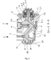
- FIG 2 shows the sectional view with the section line BB through the compressor 1 in the area of the crankshaft.
- the crankshaft housing 5 is designed as a cast part, with this B-bearing side 11 being designed to be closed.
- the carrier part 13 is arranged in the crankshaft housing 5, with the carrier part 13 being pushed into the crankshaft housing 5 and screwed to it.
- the carrier part can be designed with or without the clutch 16 and the associated actuating cylinder 15, depending on whether the compressor 1 is to be designed to be switchable or non-switchable.
- the type of design of the carrier part 13 enables flexible use, which also allows, for example, different crankcase designs to be combined with the same clutch unit 16 in the carrier part 13 .
- a prefabricated structural unit consisting of carrier part 13 and clutch 16 can simply be plugged onto crankshaft 8, pushed into the crankcase and screwed for axial and radial fixation.
- crankshaft 8 is mounted via the B-bearing directly opposite the crankshaft housing 5 and on the carrier part side via the A-bearing 12 which is arranged in the carrier part 13 .
- the support member is centered in the crankcase 5 via a fit and is located entirely within the crankcase 5 .
- the lubricating oil circuit is off figure 2 to recognize.
- the necessary lubricating oil is pumped by a device or pump, not shown here, preferably from the oil sump of the drive motor, to the lubricating oil connection 10 on the crankcase 5 . From there it reaches the lubricating oil channel 9.1 to 9.6 via the B-bearing 11. A partial oil flow reaches all bearing points via the lubricating oil channel 9.1 to 9.6, which supplies the bearings with oil or flows through them, with the partial oil flows collecting again in the crankshaft housing and being returned to the engine oil sump via the connecting channels 21 in the carrier part 13.
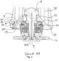
- FIG 3 shows the section AA through the compressor flange area. From this representation it can be seen how the actuating cylinder 15 is controlled to actuate the clutch 16 . Compressed air reaches the cylinder chamber of the actuating cylinder 15 via the control air connection 14 and the control air duct 25 when the latter is to be moved into the open position. If there is no compressed air, the clutch 15 is closed and the compressor 1 is driven.
- the control air duct 25 runs through the crankshaft housing 5 and the support part 13, with a separating plane running at an angle to the axis of rotation being provided between the crankshaft housing 5 and the support part 13.
- the separation point can be sealed with a simple O-ring seal.
- the screw plug 22a closes the control air duct 25, which is very easy to manufacture due to its sloping shape.
- the lubricating oil channel 9.1 to 9.6 is also closed on the motor connection side by means of a screw plug 22b.
- the structure described also has the advantage that the structure is significantly simplified and the manufacturing costs can be reduced. Furthermore, the weight is reduced because additional flanges, such as the carrier part flange and the B bearing cap flange, are no longer required thanks to the simple design.
Landscapes
- Engineering & Computer Science (AREA)
- Mechanical Engineering (AREA)
- General Engineering & Computer Science (AREA)
- Chemical & Material Sciences (AREA)
- Combustion & Propulsion (AREA)
- Compressor (AREA)
Description
- Die Erfindung betrifft einen Hubkolbenkompressor zum Anbau an und Antrieb über einen Verbrennungsmotor. Ein derartiger Hubkolbenkompressor umfasst ein Kurbelgehäuse, ein Trägerteil und eine Kurbelwelle, die mittels einem A-Lager und einem B-Lager gegenüber dem Kurbelgehäuse drehbar gelagert ist.
- Ein derartiger Hubkolbenkompressor ist beispielsweise aus der
DE 4 110 912 A1 bekannt. Es handelt sich hier um einen einstufigen Verdichter zum Verdichten eines Gases. Die Kurbelwelle ist über ein erstes und zweites Lager gegenüber dem Kurbelgehäuse gelagert. Weiterhin ist ein Flansch vorgesehen der gegenüber dem Kurbelgehäuse zentriert ist und stirnseitig am Kurbelgehäuse angeschraubt ist. Zwischen Flansch und Kurbelwelle ist das zweite Lager angeordnet. Bei dieser Variante wird in Axialrichtung für den Flansch ein Bauraum benötigt.. - Bekannt sind auch Kompressoren die eine zusätzliche Kupplung zwischen Kompressor und Antriebsmotor aufweisen. Aus der
DE 3 511 607 A1 ist ein derartiger Kompressor bekannt, bei dem die Kupplungseinrichtung in dem Kompressorgehäuse angeordnet ist und zumindest mit einem wenigstens ein Koppelmittel beinhaltenden Bereich aus dem Gehäuse des Kompressors hinausragt. Durch die Kupplung wird der benötigte Bauraum in Axialrichtung vergrößert, so dass derartige Kompressoren meist zu lang sind um in einen vorgegebenen Bauraum montiert werden zu können. - Eine weitere Ausführung ist aus der
DE10 2009 020 070 A1 bekannt. Bei dieser Lösung ist das Lager auf der Antriebsseite direkt im Kurbelgehäuse angeordnet und die Kupplung komplett außerhalb des Kurbelgehäuses. - Eine der Aufgaben der Erfindung ist es, einen Aufbau für einen Hubkolbenkompressor vorzuschlagen der mit und ohne Kupplung einen möglichst kleinen Bauraum in Axialrichtung benötigt und einfacher aufgebaut ist.
- Die Aufgabe wird erfindungsgemäß durch eine Ausführung entsprechend Anspruch 1 gelöst. Weitere vorteilhafte Merkmale der erfindungsgemäßen Ausführung finden sich in den Unteransprüchen.
- Bei der Erfindung geht es um einen Hubkolbenkompressor, zum Anbau an und Antrieb über einen Verbrennungsmotor, umfassend ein Kurbelgehäuse, ein Trägerteil und eine Kurbelwelle die mittels einem A-Lager und einem B-Lager gegenüber dem Kurbelgehäuse drehbar gelagert ist. Dabei ist zwischen Kompressor und Verbrennungsmotor das A-Lager angeordnet.
- Erfindungsgemäß wird vorgeschlagen, dass das Trägerteil zwischen A-Lager und Kurbelwellengehäuse angeordnet ist, wobei das Trägerteil im Wesentlichen in das Kurbelwellengehäuse eingeschoben ist und durch dieses zentriert wird. Durch das Einschieben in das Kurbelwellengehäuse wird der Aufbau und die Montierbarkeit verbessert. So werden beispielweise die Fluchtungstoleranzen zwischen den Lager A und B verringert. Des Weiteren hat das Trägerteil hat keinen Flansch mehr, über den der Kompressor in StdT mit dem Motor verbunden wurde. Das Trägerteil braucht nun nur noch gegen Verdrehen mit dem Kurbelwellengehäuse verschraubt werden.
- Weiterhin wird vorgeschlagen, dass für die Kopplung zwischen Verbrennungsmotor und Hubkolbenkompressor ein Zentrieransatz und eine Flanschverbindung am Kurbelwellengehäuse vorgesehen sind. Das Kurbelwellengehäuse kann so direkt am Verbrennungsmotor angeflanscht werden. Es ist nur noch eine Dichtung zwischen Kompressor und Antriebsmotor notwendig.
- In einer Ausführung kann zwischen Kurbelwelle und Trägerteil eine schaltbare Kupplung angeordnet sein, mittels der eine Antriebsleistung von einem auf der Kurbelwelle drehbar gelagerten Antriebsrad auf die Kurbelwelle übertragbar ist.
- Dabei sind die Primärseite der Kupplung mit dem Antriebsrad, z.B. Zahnrad und die Sekundärseite der Kupplung mit der Kurbelwelle drehfest gekoppelt. Vorzugsweise ist die Kupplung im nicht betätigten Zustand in der Schließstellung, so dass der Kompressor angetrieben wird. So wird sichergestellt, dass der Kompressor nur abgestellt wird, wenn dies aktiv beabsichtigt ist.
- Die Kupplung kann beispielsweise einen pneumatisch betätigbaren Zylinder umfassen, der über einen Steuerluftanschluss im Kurbelwellengehäuse mit Druckluft versorgbar ist. Der Steuerluftkanal verläuft durch das Kurbelwellengehäuse und das Trägerteil, wobei eine winkelig zur Drehachse verlaufende Trennebene zwischen Kurbelwellengehäuse und Trägerteil vorgesehen ist. Durch die winklige Anordnung der Trennebene erhält man eine einfach zu dichtende Nahtstelle zwischen den Bauteilen, die mittels eines einfachen O-Rings abgedichtet werden kann und die gleichzeitig eine kostengünstige Fertigung erlaubt.
- In einer bevorzugten Ausführung ist das Kurbelwellengehäuse als Gußteil ausgeführt, das in Axialrichtung gesehen B-Lagerseitig geschlossen ausgeführt ist, wobei ein Schmierölanschluss vorgesehen ist über den das B-Lager mit Schmieröl versorgbar ist. B-Lagerseitig entfällt damit der Lagerdeckel wie er im StdT üblich ist.
- Zur Sicherstellung der Lagerschmierung wird weiterhin vorgeschlagen, dass der Schmierölanschluss über das B-Lager mit einem durch die Kurbelwelle verlaufenden Schmierölkanal verbunden ist, über den das A-Lager, die Kupplung und weitere Lagerstellen des Hubkolbenkompressors mit Schmieröl versorgbar sind. Die weiteren Lagerstellen sind beispielsweise die Pleuellager.
- Weiterhin ist vorgesehen, dass der Kurbelwellenraum des Kurbelwellengehäuses über Verbindungskanäle im Trägerteil mit dem Ölraum des Verbrennungsmotors verbindbar ist, so dass überschüssiges Öl in den Motorölsumpf zurückfließen kann.
- Weiterhin wird ein Schmierölkreislauf durch einen Hubkolbenkompressor wie oben beschrieben vorgeschlagen bei dem eine Vorrichtung vorgesehen ist, mittels der Schmieröl über den Schmierölanschluss und das B-Lager in den Schmierölkanal pumpbar ist, wobei jede Lagerstelle des Kompressors von einem Teilölstrom durchflossen wird, wobei sich die Teilströme im Kurbelwellengehäuse nach dem durchströmen der Lagerstellen sammeln und über die Verbindungskanäle im Trägerteil in den Motorölsumpf zurückgeführt werden.
- Anhand von Ausführungsbeispielen werden weitere vorteilhafte Ausprägungen der Erfindung unter Bezugnahme auf die Zeichnungen erläutert. Die genannten Merkmale können nicht nur in der dargestellten Kombination vorteilhaft umgesetzt werden, sondern auch einzeln untereinander kombiniert werden.
- Die Figuren zeigen im Einzelnen:
- Fig.1
- Ansicht auf den Anschlussflansch des Kompressors
- Fig.2
- Schnitt B-B durch den Kompressor im Bereich der Kurbelwelle
- Fig.3
- Schnitt A-A durch den Kompressorflanschbereich
-
Figur 1 zeigt eine Ansicht des Hubkolbenkompressors in Richtung des Anschlussflansches. Zu sehen ist der Zylinderkopf 4 das Kurbelgehäuse 5, mit dem Zylinderbereich oben und dem Kurbelwellenbereich unten. Über den Kompressorflansch 19, der einstückig mit dem Kurbelwellengehäuse 5 ausgeführt ist, wird der Kompressor 1 an den Motorgehäuse befestigt. -
Figur 2 zeigt die Schnittdarstellung mit dem Schnittverlauf B-B durch den Kompressor 1 im Bereich der Kurbelwelle. Das Kurbelwellengehäuse 5 ist als Gußteil ausgeführt, wobei dieses B-Lagerseitig 11 geschlossen ausgeführt ist. A-Lagerseitig 12 ist das Trägerteil 13 in dem Kurbelwellengehäuse 5 angeordnet, wobei das Trägerteil 13 in das Kurbelwellengehäuse 5 eingeschoben und mit diesem verschraubt ist. Das Trägerteil kann mit und ohne die Kupplung 16 und dem dazugehörigen Betätigungszylinder 15 ausgeführt sein, je nachdem ob der Kompressor 1 schaltbar oder nichtschaltbar ausgeführt sein soll. - Die Art der Ausführung des Trägerteils 13 ermöglicht einen flexiblen Einsatz, der es beispielsweise auch erlaubt, dass unterschiedliche Kurbelwellengehäuseausführungen mit der gleichen Kupplungseinheit 16 im Trägerteil 13 kombiniert werden können.
- So kann eine vorgefertigte Baueinheit aus Trägerteil 13 und Kupplung 16 einfach auf die Kurbelwelle 8 aufgesteckt, in das Kurbelgehäuse geschoben und zur axialen und radialen Fixierung verschraubt werden.
- Die Lagerung der Kurbelwelle 8 erfolgt über das B-Lager direkt gegenüber dem Kurbelwellengehäuse 5 und auf der Trägerteilseite über das A-Lager 12 welches in dem Trägerteil 13 angeordnet ist. Das Trägerteil ist über eine Passung im Kurbelwellengehäuse 5 zentriert und ist vollständig innerhalb des Kurbelwellengehäuses 5 angeordnet.
- Weiterhin ist der Schmierölkreislauf aus
Figur 2 zu erkennen. Das notwendige Schmieröl wird von einer hier nicht dargestellten Vorrichtung bzw. Pumpe, vorzugsweise aus dem Ölsumpf des Antriebsmotors, zum Schmierölanschluss 10 am Kurbelwellengehäuse 5 gepumpt. Von dort gelangt es über das B-Lager 11 in den Schmierölkanal 9.1 bis 9.6. Über den Schmierölkanal 9.1 bis 9.6 gelangt an alle Lagerstellen ein Teilölstrom, der die Lager mit Öl versorgt bzw. diese durchströmt, wobei sich die Teilölströme im Kurbelwellengehäuse wieder sammeln und über die Verbindungskanäle 21 im Trägerteil 13 in den Motorölsumpf zurückgeführt werden. - Da sich durch den B-Lagerseitigen geschlossenen Aufbau des Kurbelwellengehäuses 5 eine Kammer 28 zwischen Kurbelwellengehäuse 5 und Kurbelwelle 8 bildet ist es notwendig, dass ein Ölabflusskanal 29 vorgesehen wird. Dieser lässt sich durch den vorteilhaften Gehäuseaufbau sehr einfach über die Zylindermontageöffnung 6 bohren.
-
Figur 3 zeigt den Schnitt A-A durch den Kompressorflanschbereich. Aus dieser Darstellung ist zu erkennen wie der Betätigungszylinder 15 zur Betätigung der Kupplung 16 angesteuert wird. Über den Steuerluftanschluss 14 und den Steuerluftkanal 25 gelangt Druckluft in den Zylinderraum des Betätigungszylinders 15, wenn dieser in die Offenstellung bewegt werden soll. Liegt keine Druckluft an ist die Kupplung 15 geschlossen und der Kompressor 1 wird angetrieben. - Der Steuerluftkanal 25 verläuft durch das Kurbelwellengehäuse 5 und das Trägerteil 13, wobei eine winkelig zur Drehachse verlaufende Trennebene zwischen Kurbelwellengehäuse 5 und Trägerteil 13 vorgesehen ist. Die Trennstelle lässt sich mittels einer einfachen O-Ring Dichtung abdichten. Die Verschlussschraube 22a verschließt den Steuerluftkanal 25, der durch seinen schrägen Verlauf sehr einfach zu fertigen ist.
- Auch der Schmierölkanal 9.1 bis 9.6 ist ebenfalls auf der Motoranschlussseite mittels einer Verschlussschraube 22b verschlossen.
- Durch den beschriebenen Aufbau ergibt sich weiterhin der Vorteil, dass der Aufbau wesentlich vereinfacht wird und die Herstellungskosten reduziert werden können. Weiterhin reduziert sich das Gewicht, da durch den einfachen Aufbau zusätzliche Flansche wegfallen, wie der Trägerteilflansch und der B-Lagerdeckelflansch.
-
- 1
- Hubkolbenkompressor
- 2
- erste Verdichterstufe
- 3
- zweite Verdichterstufe
- 4
- Zylinderkopf
- 5
- Kurbelgehäuse
- 6
- Verschlussdeckel - Zylindermontageöffnung
- 7
- Pleuel
- 8
- Kurbelwelle
- 9.1- 9.6
- Schmierölkanal
- 10
- Schmierölanschluss
- 11
- B-Lager
- 12
- A-Lager
- 13
- Trägerteil
- 14
- Steuerluftanschluss
- 15
- Betätigungszylinder
- 16
- Kupplung
- 17
- Dichtung
- 18
- Flanschverschraubung
- 19
- Kompressorflansch
- 20
- Zahnrad
- 21
- Verbindungskanäle
- 22a, b
- Verschlussstopfen
- 24
- Zylinder
- 25
- Steuerluftkanal
- 26
- Trennebene
- 27
- Zentrieransatz
- 28
- Kammer
- 29
- Ölabflusskanal
- 30
- Ölraum
Claims (8)
- Hubkolbenkompressor (1), zum Anbau an und Antrieb über einen Verbrennungsmotor, umfassend ein Kurbelgehäuse (5), ein Trägerteil (13) und eine Kurbelwelle (8) die mittels einem B-Lager (11) und einem A-Lager (12) gegenüber dem Kurbelwellengehäuse (5) drehbar gelagert ist,
dadurch gekennzeichnet,dass das Trägerteil (13) zwischen A-Lager (12) und Kurbelwellengehäuse (5) angeordnet ist, wobei das Trägerteil (13) vollständig innerhalb des Kurbelwellengehäuses (5) angeordnet ist und durch dieses zentriert wird, und zwischen Kurbelwelle (8) und Trägerteil (13) eine Bauraum für eine schaltbare Kupplung (16) angeordnet ist, mittels der eine Antriebsleistung von einem auf der Kurbelwelle (8) drehbar gelagerten Antriebsrad (20) auf die Kurbelwelle (8) übertragbar ist unddas Kurbelwellengehäuse (5) als Gußteil ausgeführt ist, das in Axialrichtung B-Lagerseitig geschlossen ausgeführt ist. - Hubkolbenkompressor (1) nach Anspruch 1
dadurch gekennzeichnet,
dass für die Kopplung zwischen Verbrennungsmotor und Hubkolbenkompressor (1) ein Zentrieransatz (27) und eine Flanschverbindung (19) am Kurbelwellengehäuse (5) vorgesehen sind. - Hubkolbenkompressor (1) nach Anspruch 1
dadurch gekennzeichnet,
dass zwischen Kurbelwelle (8) und Trägerteil (13) eine schaltbare Kupplung (16) angeordnet ist, mittels der eine Antriebsleistung von einem auf der Kurbelwelle (8) drehbar gelagerten Antriebsrad (20) auf die Kurbelwelle (8) übertragbar ist. - Hubkolbenkompressor (1) nach Anspruch 2
dadurch gekennzeichnet,
dass die Kupplung (16) einen pneumatisch betätigbaren Zylinder (24) umfasst, der über einen Steuerluftanschluss (14) im Kurbelwellengehäuse (5) mit Druckluft versorgbar ist, wobei ein Steuerluftkanal (25) durch das Kurbelwellengehäuse (5) und das Trägerteil (13) verläuft, wobei eine winkelig zur Drehachse verlaufende Trennebene (26) zwischen Kurbelwellengehäuse (5) und Trägerteil (13) vorgesehen ist. - Hubkolbenkompressor (1) nach Anspruch 1
dadurch gekennzeichnet,
dass ein Schmierölanschluss (10) vorgesehen ist über den das B-Lager (11) mit Schmieröl versorgbar ist. - Hubkolbenkompressor (1) nach Anspruch 1
dadurch gekennzeichnet,
dass der Schmierölanschluss (10) über das B-Lager (11) mit einem durch die Kurbelwelle (8) verlaufenden Schmierölkanal (9.1 bis 9.6) verbunden ist, über den das A-Lager (12), die Kupplung (16) und weitere Lagerstellen des Hubkolbenkompressors (1) mit Schmieröl versorgbar sind. - Hubkolbenkompressor (1) nach Anspruch 1
dadurch gekennzeichnet,
dass der Kurbelwellenraum (30) des Kurbelwellengehäuses (5) über Verbindungskanäle (21) im Trägerteil (13) mit dem Ölraum des Verbrennungsmotors verbindbar ist, so dass überschüssiges Öl in den Motorölsumpf zurückfließen kann. - Hubkolbenkompressor (1) nach einem der Ansprüche 1 bis 7
dadurch gekennzeichnet,
dass das eine Vorrichtung vorgesehen ist, mittels der Schmieröl über den Schmierölanschluss (10) und das B-Lager (11) in den Schmierölkanal (9.1 bis 9.6) pumpbar ist, wobei jede Lagerstelle von einem Teilölstrom durchflossen wird, wobei sich die Teilölströme im Kurbelwellengehäuse (5) wieder sammeln und über die Verbindungskanäle (21) im Trägerteil (13) in den Motorölsumpf zurückgeführt werden.
Applications Claiming Priority (2)
| Application Number | Priority Date | Filing Date | Title |
|---|---|---|---|
| DE102018119924.4A DE102018119924A1 (de) | 2018-08-16 | 2018-08-16 | Hubkolbenkompressor |
| PCT/EP2019/069733 WO2020035266A1 (de) | 2018-08-16 | 2019-07-23 | Hubkolbenkompressor |
Publications (3)
| Publication Number | Publication Date |
|---|---|
| EP3837439A1 EP3837439A1 (de) | 2021-06-23 |
| EP3837439B1 true EP3837439B1 (de) | 2023-06-28 |
| EP3837439C0 EP3837439C0 (de) | 2023-06-28 |
Family
ID=67441103
Family Applications (1)
| Application Number | Title | Priority Date | Filing Date |
|---|---|---|---|
| EP19745087.7A Active EP3837439B1 (de) | 2018-08-16 | 2019-07-23 | Hubkolbenkompressor |
Country Status (3)
| Country | Link |
|---|---|
| EP (1) | EP3837439B1 (de) |
| DE (1) | DE102018119924A1 (de) |
| WO (1) | WO2020035266A1 (de) |
Family Cites Families (14)
| Publication number | Priority date | Publication date | Assignee | Title |
|---|---|---|---|---|
| US3211365A (en) * | 1961-10-16 | 1965-10-12 | Copeland Refrigeration Corp | Compressor structure |
| GB1082686A (en) * | 1963-06-27 | 1967-09-06 | J & E Hall Ltd | Improvements in and relating to compressors |
| US3335942A (en) * | 1966-01-03 | 1967-08-15 | John W Seigart | Hermetic motor compressor |
| DE8021411U1 (de) * | 1980-08-09 | 1980-11-13 | Knorr-Bremse Gmbh, 8000 Muenchen | Regeleinrichtung fuer einen kompressor, insbesondere zum betrieb in kraftfahrzeugen |
| GB2162255B (en) * | 1984-03-30 | 1988-02-03 | Grau Girling Limited | Multi-plate clutch in an air compressor |
| US4657127A (en) * | 1984-06-19 | 1987-04-14 | Baruffaldi Frizioni Spa | Clutch for linking a compressor with a drive means therefor |
| ES2023819B3 (es) * | 1986-12-12 | 1992-02-16 | Bendix Ltd | Montaje compresor |
| DE4110912A1 (de) * | 1990-04-18 | 1991-10-24 | Bauer Kompressoren | Trockenlaufender hubkolben-kompressor |
| GB9625938D0 (en) * | 1996-12-13 | 1997-01-29 | Knorr Bremse Systeme | Clutch driven gas compressor |
| EP1995482B1 (de) * | 2007-05-25 | 2012-07-18 | Hoerbiger Drivetrain Mechatronics B.V.B.A. | Motor-Kompressor-Einheit |
| DE102009012214A1 (de) | 2009-03-07 | 2009-10-29 | Daimler Ag | Radspoileranordnung für ein Fahrzeug |
| DE102009018842A1 (de) | 2009-04-17 | 2010-10-21 | Juliane Delkeskamp | Vorrichtung zur Visualisierung |
| DE102009020070A1 (de) * | 2009-05-06 | 2010-11-11 | Wabco Gmbh | Kompressor mit Kupplungseinrichtung |
| DE102016014787A1 (de) * | 2016-12-10 | 2018-06-14 | Wabco Gmbh | Verdichteranordnung, Druckluftversorgungsanlage zum Betreiben einer Pneumatikanlage und Verfahren zur Montage einer Verdichteranordnung |
-
2018
- 2018-08-16 DE DE102018119924.4A patent/DE102018119924A1/de active Pending
-
2019
- 2019-07-23 EP EP19745087.7A patent/EP3837439B1/de active Active
- 2019-07-23 WO PCT/EP2019/069733 patent/WO2020035266A1/de not_active Ceased
Also Published As
| Publication number | Publication date |
|---|---|
| WO2020035266A1 (de) | 2020-02-20 |
| EP3837439A1 (de) | 2021-06-23 |
| DE102018119924A1 (de) | 2020-02-20 |
| EP3837439C0 (de) | 2023-06-28 |
Similar Documents
| Publication | Publication Date | Title |
|---|---|---|
| EP1843012B1 (de) | Brennkraftmaschine mit einer Vorrichtung zur hydraulischen Drehwinkelverstellung ihrer Nockenwelle gegenüber ihrer Kurbelwelle sowie mit einer Vakuumpumpe für einen Servorverbraucher, insbesondere für einen Bremskraftverstärker | |
| DE19941891B4 (de) | Wasserpumpenanordnung für einen Motor | |
| EP0515929B1 (de) | An einem Motorgehäuse eines Kraftfahrzeugmotors befestigte Flügelzellenvakuumpumpe | |
| DE102013022320B4 (de) | Anbindung eines Verstellaktuators an ein Zentralventilsystem für einen trockenen Riementrieb | |
| DE102014208775A1 (de) | Gasflügelpumpe und Verfahren zum Betrieb der Gasflügelpumpe | |
| EP1948938B1 (de) | Pumpe mit zylindrischer kühlbuchse | |
| DE10305781B4 (de) | Mehrstufige Schmierölpumpe | |
| EP1310672B1 (de) | Kraftstoff-Pumpeinrichtung für ein Kraftstoffsystem einer Brennkraftmaschine sowie Kraftstoffsystem | |
| WO2020035266A1 (de) | Hubkolbenkompressor | |
| WO2020007396A1 (de) | Leitungselement, hybridmodul und antriebsanordnung | |
| DE10149388A1 (de) | Fluidpumpe, insbesondere Hydraulik- oder Schmiermittelpumpe, für eine Brennkraftmaschine, sowie Baueinheit aus mindestens zwei Fluidpumpen für eine Brennkraftmaschine | |
| DE102012017325B4 (de) | Abgasturbolader | |
| DE102009020070A1 (de) | Kompressor mit Kupplungseinrichtung | |
| EP1315906B1 (de) | Kolbenkompressor mit dynamisch massenausgeglichener kurbelwelle, insbesondere für schienenfahrzeuge (lösbare ausgleichsmasse) | |
| EP1264965A2 (de) | Lagergehäuse eines Abgasturboladers für eine Brennkraftmaschine | |
| WO2014063681A1 (de) | Intermittierende kupplungsbeölung | |
| DE10240316A1 (de) | Klappenelement und Klappenanordnung | |
| DE19737491A1 (de) | Brennkraftmaschine mit mehreren zur Öl- und Kraftstoffversorgung vorgesehenen Einrichtungen | |
| DE102013114304A1 (de) | Kompressorsystem mit einer Kolbenhubeinstellvorrichtung | |
| DE102007055225A1 (de) | Ladeeinrichtung | |
| DE102017118190A1 (de) | Nockenwellenverstellsystem | |
| DE102023210509A1 (de) | Pumpeneinheit für Schmiermittelpumpe | |
| DE102015216867A1 (de) | Kühlmittelregler mit robuster Lagerung und Wärmekraftmaschine | |
| DE102019217295A1 (de) | Nockenwellen-Anordnung | |
| WO2025087696A1 (de) | Pumpeneinheit für eine schmiermittelpumpe |
Legal Events
| Date | Code | Title | Description |
|---|---|---|---|
| STAA | Information on the status of an ep patent application or granted ep patent |
Free format text: STATUS: UNKNOWN |
|
| STAA | Information on the status of an ep patent application or granted ep patent |
Free format text: STATUS: THE INTERNATIONAL PUBLICATION HAS BEEN MADE |
|
| PUAI | Public reference made under article 153(3) epc to a published international application that has entered the european phase |
Free format text: ORIGINAL CODE: 0009012 |
|
| STAA | Information on the status of an ep patent application or granted ep patent |
Free format text: STATUS: REQUEST FOR EXAMINATION WAS MADE |
|
| 17P | Request for examination filed |
Effective date: 20210316 |
|
| AK | Designated contracting states |
Kind code of ref document: A1 Designated state(s): AL AT BE BG CH CY CZ DE DK EE ES FI FR GB GR HR HU IE IS IT LI LT LU LV MC MK MT NL NO PL PT RO RS SE SI SK SM TR |
|
| DAV | Request for validation of the european patent (deleted) | ||
| DAX | Request for extension of the european patent (deleted) | ||
| GRAP | Despatch of communication of intention to grant a patent |
Free format text: ORIGINAL CODE: EPIDOSNIGR1 |
|
| STAA | Information on the status of an ep patent application or granted ep patent |
Free format text: STATUS: GRANT OF PATENT IS INTENDED |
|
| RIC1 | Information provided on ipc code assigned before grant |
Ipc: F04B 39/14 20060101ALI20230119BHEP Ipc: F04B 39/12 20060101ALI20230119BHEP Ipc: F04B 39/00 20060101ALI20230119BHEP Ipc: F04B 35/01 20060101ALI20230119BHEP Ipc: F04B 17/05 20060101AFI20230119BHEP |
|
| INTG | Intention to grant announced |
Effective date: 20230203 |
|
| GRAS | Grant fee paid |
Free format text: ORIGINAL CODE: EPIDOSNIGR3 |
|
| GRAA | (expected) grant |
Free format text: ORIGINAL CODE: 0009210 |
|
| STAA | Information on the status of an ep patent application or granted ep patent |
Free format text: STATUS: THE PATENT HAS BEEN GRANTED |
|
| AK | Designated contracting states |
Kind code of ref document: B1 Designated state(s): AL AT BE BG CH CY CZ DE DK EE ES FI FR GB GR HR HU IE IS IT LI LT LU LV MC MK MT NL NO PL PT RO RS SE SI SK SM TR |
|
| REG | Reference to a national code |
Ref country code: CH Ref legal event code: EP |
|
| REG | Reference to a national code |
Ref country code: AT Ref legal event code: REF Ref document number: 1582894 Country of ref document: AT Kind code of ref document: T Effective date: 20230715 |
|
| REG | Reference to a national code |
Ref country code: IE Ref legal event code: FG4D Free format text: LANGUAGE OF EP DOCUMENT: GERMAN |
|
| REG | Reference to a national code |
Ref country code: DE Ref legal event code: R096 Ref document number: 502019008343 Country of ref document: DE |
|
| U01 | Request for unitary effect filed |
Effective date: 20230718 |
|
| U07 | Unitary effect registered |
Designated state(s): AT BE BG DE DK EE FI FR IT LT LU LV MT NL PT SE SI Effective date: 20230725 |
|
| REG | Reference to a national code |
Ref country code: LT Ref legal event code: MG9D |
|
| PG25 | Lapsed in a contracting state [announced via postgrant information from national office to epo] |
Ref country code: NO Free format text: LAPSE BECAUSE OF FAILURE TO SUBMIT A TRANSLATION OF THE DESCRIPTION OR TO PAY THE FEE WITHIN THE PRESCRIBED TIME-LIMIT Effective date: 20230928 |
|
| PG25 | Lapsed in a contracting state [announced via postgrant information from national office to epo] |
Ref country code: RS Free format text: LAPSE BECAUSE OF FAILURE TO SUBMIT A TRANSLATION OF THE DESCRIPTION OR TO PAY THE FEE WITHIN THE PRESCRIBED TIME-LIMIT Effective date: 20230628 Ref country code: HR Free format text: LAPSE BECAUSE OF FAILURE TO SUBMIT A TRANSLATION OF THE DESCRIPTION OR TO PAY THE FEE WITHIN THE PRESCRIBED TIME-LIMIT Effective date: 20230628 Ref country code: GR Free format text: LAPSE BECAUSE OF FAILURE TO SUBMIT A TRANSLATION OF THE DESCRIPTION OR TO PAY THE FEE WITHIN THE PRESCRIBED TIME-LIMIT Effective date: 20230929 |
|
| U20 | Renewal fee for the european patent with unitary effect paid |
Year of fee payment: 5 Effective date: 20231106 |
|
| PG25 | Lapsed in a contracting state [announced via postgrant information from national office to epo] |
Ref country code: SK Free format text: LAPSE BECAUSE OF FAILURE TO SUBMIT A TRANSLATION OF THE DESCRIPTION OR TO PAY THE FEE WITHIN THE PRESCRIBED TIME-LIMIT Effective date: 20230628 |
|
| PG25 | Lapsed in a contracting state [announced via postgrant information from national office to epo] |
Ref country code: ES Free format text: LAPSE BECAUSE OF FAILURE TO SUBMIT A TRANSLATION OF THE DESCRIPTION OR TO PAY THE FEE WITHIN THE PRESCRIBED TIME-LIMIT Effective date: 20230628 |
|
| PG25 | Lapsed in a contracting state [announced via postgrant information from national office to epo] |
Ref country code: IS Free format text: LAPSE BECAUSE OF FAILURE TO SUBMIT A TRANSLATION OF THE DESCRIPTION OR TO PAY THE FEE WITHIN THE PRESCRIBED TIME-LIMIT Effective date: 20231028 |
|
| PG25 | Lapsed in a contracting state [announced via postgrant information from national office to epo] |
Ref country code: SM Free format text: LAPSE BECAUSE OF FAILURE TO SUBMIT A TRANSLATION OF THE DESCRIPTION OR TO PAY THE FEE WITHIN THE PRESCRIBED TIME-LIMIT Effective date: 20230628 Ref country code: SK Free format text: LAPSE BECAUSE OF FAILURE TO SUBMIT A TRANSLATION OF THE DESCRIPTION OR TO PAY THE FEE WITHIN THE PRESCRIBED TIME-LIMIT Effective date: 20230628 Ref country code: RO Free format text: LAPSE BECAUSE OF FAILURE TO SUBMIT A TRANSLATION OF THE DESCRIPTION OR TO PAY THE FEE WITHIN THE PRESCRIBED TIME-LIMIT Effective date: 20230628 Ref country code: IS Free format text: LAPSE BECAUSE OF FAILURE TO SUBMIT A TRANSLATION OF THE DESCRIPTION OR TO PAY THE FEE WITHIN THE PRESCRIBED TIME-LIMIT Effective date: 20231028 Ref country code: ES Free format text: LAPSE BECAUSE OF FAILURE TO SUBMIT A TRANSLATION OF THE DESCRIPTION OR TO PAY THE FEE WITHIN THE PRESCRIBED TIME-LIMIT Effective date: 20230628 Ref country code: CZ Free format text: LAPSE BECAUSE OF FAILURE TO SUBMIT A TRANSLATION OF THE DESCRIPTION OR TO PAY THE FEE WITHIN THE PRESCRIBED TIME-LIMIT Effective date: 20230628 |
|
| PG25 | Lapsed in a contracting state [announced via postgrant information from national office to epo] |
Ref country code: PL Free format text: LAPSE BECAUSE OF FAILURE TO SUBMIT A TRANSLATION OF THE DESCRIPTION OR TO PAY THE FEE WITHIN THE PRESCRIBED TIME-LIMIT Effective date: 20230628 |
|
| REG | Reference to a national code |
Ref country code: CH Ref legal event code: PL |
|
| PG25 | Lapsed in a contracting state [announced via postgrant information from national office to epo] |
Ref country code: MC Free format text: LAPSE BECAUSE OF FAILURE TO SUBMIT A TRANSLATION OF THE DESCRIPTION OR TO PAY THE FEE WITHIN THE PRESCRIBED TIME-LIMIT Effective date: 20230628 |
|
| PG25 | Lapsed in a contracting state [announced via postgrant information from national office to epo] |
Ref country code: MC Free format text: LAPSE BECAUSE OF FAILURE TO SUBMIT A TRANSLATION OF THE DESCRIPTION OR TO PAY THE FEE WITHIN THE PRESCRIBED TIME-LIMIT Effective date: 20230628 |
|
| REG | Reference to a national code |
Ref country code: DE Ref legal event code: R097 Ref document number: 502019008343 Country of ref document: DE |
|
| REG | Reference to a national code |
Ref country code: IE Ref legal event code: MM4A |
|
| PG25 | Lapsed in a contracting state [announced via postgrant information from national office to epo] |
Ref country code: CH Free format text: LAPSE BECAUSE OF NON-PAYMENT OF DUE FEES Effective date: 20230731 |
|
| PLBE | No opposition filed within time limit |
Free format text: ORIGINAL CODE: 0009261 |
|
| STAA | Information on the status of an ep patent application or granted ep patent |
Free format text: STATUS: NO OPPOSITION FILED WITHIN TIME LIMIT |
|
| GBPC | Gb: european patent ceased through non-payment of renewal fee |
Effective date: 20230928 |
|
| 26N | No opposition filed |
Effective date: 20240402 |
|
| PG25 | Lapsed in a contracting state [announced via postgrant information from national office to epo] |
Ref country code: IE Free format text: LAPSE BECAUSE OF NON-PAYMENT OF DUE FEES Effective date: 20230723 |
|
| PG25 | Lapsed in a contracting state [announced via postgrant information from national office to epo] |
Ref country code: GB Free format text: LAPSE BECAUSE OF NON-PAYMENT OF DUE FEES Effective date: 20230928 |
|
| PG25 | Lapsed in a contracting state [announced via postgrant information from national office to epo] |
Ref country code: IE Free format text: LAPSE BECAUSE OF NON-PAYMENT OF DUE FEES Effective date: 20230723 Ref country code: GB Free format text: LAPSE BECAUSE OF NON-PAYMENT OF DUE FEES Effective date: 20230928 |
|
| U20 | Renewal fee for the european patent with unitary effect paid |
Year of fee payment: 6 Effective date: 20240731 |
|
| PG25 | Lapsed in a contracting state [announced via postgrant information from national office to epo] |
Ref country code: CY Free format text: LAPSE BECAUSE OF FAILURE TO SUBMIT A TRANSLATION OF THE DESCRIPTION OR TO PAY THE FEE WITHIN THE PRESCRIBED TIME-LIMIT; INVALID AB INITIO Effective date: 20190723 |
|
| PG25 | Lapsed in a contracting state [announced via postgrant information from national office to epo] |
Ref country code: HU Free format text: LAPSE BECAUSE OF FAILURE TO SUBMIT A TRANSLATION OF THE DESCRIPTION OR TO PAY THE FEE WITHIN THE PRESCRIBED TIME-LIMIT; INVALID AB INITIO Effective date: 20190723 |
|
| U20 | Renewal fee for the european patent with unitary effect paid |
Year of fee payment: 7 Effective date: 20250731 |
|
| PG25 | Lapsed in a contracting state [announced via postgrant information from national office to epo] |
Ref country code: TR Free format text: LAPSE BECAUSE OF FAILURE TO SUBMIT A TRANSLATION OF THE DESCRIPTION OR TO PAY THE FEE WITHIN THE PRESCRIBED TIME-LIMIT Effective date: 20230628 |