EP3837101B1 - Winkelstiftbuchse und spritzgiessschieber damit - Google Patents
Winkelstiftbuchse und spritzgiessschieber damit Download PDFInfo
- Publication number
- EP3837101B1 EP3837101B1 EP19849769.5A EP19849769A EP3837101B1 EP 3837101 B1 EP3837101 B1 EP 3837101B1 EP 19849769 A EP19849769 A EP 19849769A EP 3837101 B1 EP3837101 B1 EP 3837101B1
- Authority
- EP
- European Patent Office
- Prior art keywords
- angle pin
- slide
- mold
- pin bushing
- angle
- Prior art date
- Legal status (The legal status is an assumption and is not a legal conclusion. Google has not performed a legal analysis and makes no representation as to the accuracy of the status listed.)
- Active
Links
Images


Classifications
-
- B—PERFORMING OPERATIONS; TRANSPORTING
- B29—WORKING OF PLASTICS; WORKING OF SUBSTANCES IN A PLASTIC STATE IN GENERAL
- B29C—SHAPING OR JOINING OF PLASTICS; SHAPING OF MATERIAL IN A PLASTIC STATE, NOT OTHERWISE PROVIDED FOR; AFTER-TREATMENT OF THE SHAPED PRODUCTS, e.g. REPAIRING
- B29C45/00—Injection moulding, i.e. forcing the required volume of moulding material through a nozzle into a closed mould; Apparatus therefor
- B29C45/17—Component parts, details or accessories; Auxiliary operations
- B29C45/26—Moulds
- B29C45/33—Moulds having transversely, e.g. radially, movable mould parts
- B29C45/332—Mountings or guides therefor; Drives therefor
-
- B—PERFORMING OPERATIONS; TRANSPORTING
- B29—WORKING OF PLASTICS; WORKING OF SUBSTANCES IN A PLASTIC STATE IN GENERAL
- B29C—SHAPING OR JOINING OF PLASTICS; SHAPING OF MATERIAL IN A PLASTIC STATE, NOT OTHERWISE PROVIDED FOR; AFTER-TREATMENT OF THE SHAPED PRODUCTS, e.g. REPAIRING
- B29C45/00—Injection moulding, i.e. forcing the required volume of moulding material through a nozzle into a closed mould; Apparatus therefor
- B29C45/17—Component parts, details or accessories; Auxiliary operations
- B29C45/26—Moulds
- B29C45/33—Moulds having transversely, e.g. radially, movable mould parts
Definitions
- the present disclosure is generally directed to injection molding equipment, and more particularly to side actions or slides for injection molding.
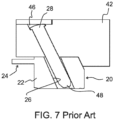
- a typical side action or slide part i.e., a slide 20 has a body 22 with a coring element 24 of some geometric form extending therefrom.
- the coring element 24 is used to form a void or desired surface or shape within a molded part.
- the coring element 24 lies in the part ejection path from the mold.
- the slide 20 is movable so that the coring element 24 can move toward the mold cavity prior to part formation and can be withdrawn from the mold cavity to permit the part to be ejected from the cavity and the mold.
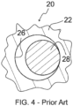
- the slide 20 has a slightly oversized round or circular shaped hole 26 in the body 22 for receiving an angle pin 28. As shown in FIGS.
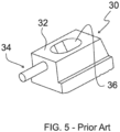
- a slide 30 is similar to the slide 20 in that it has a body 32 with a coring element 34 projecting from the body.
- the slide 30 has an elongate, non-round, oval, or oblong shaped hole, i.e., a slot 36 in the body 32.
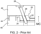
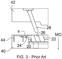
- FIGS. 2 and 3 depict a generic mold construction that incorporates the slide 20.
- the mold includes a first mold half 40 and a second mold half 42 that are movable toward and away from one another in the direction of the arrows MC and MO, respectively, i.e., "Mold Close” (MC) and "Mold Open” (MO).
- FIG. 2 shows the mold with the mold halves 40, 42 closed
- FIG. 3 shows the mold with the mold halves open.
- the mold halves 40, 42 define a mold cavity 44, which can form a molded part in the closed position of FIG. 2 , and which can eject the molded part in the open position of FIG. 3 .
- the angle pin 28 has a proximal end mounted to the mold half 42 through an opening 46 in the second mold half.
- a distal or working end 48 of the angle pin 28 protrudes from the second mold half to engage the slide 20.
- the coring element 24 extends into the mold cavity 44 to form a void, space, or other shape in a molded part.
- the coring element 24 must move out of the way to clear the mold cavity 44.
- the working end 48 of the angle pin 28 and the hole 26 in this example, move the slide 20 in a direction perpendicular to the mold open/close directions MO/MC.
- the coring element 24 is simultaneously moved outward from the cavity 44 as the mold halves 40, 42 are separated in the direction MO to the open position of FIG. 3 , allowing for the molded part to be ejected from the cavity 44.
- the hole 26 diameter or slot 36 radius are always oversized so that the motion, i.e., the stroke S of the slide 20 (or 30) can be achieved, as depicted in FIGS. 2 and 3 .
- This is typically referenced as “fit” or “running fit”.
- this running fit is very loose by virtually any standard so as not to add additional force requirements to facilitate the mold opening process.
- This conventional loose fit is depicted in FIGS. 4 and 6 .
- This loose fit also allows for pin deflection without binding and breaking the angle pin 28 under load.
- the typical hole size could be 0.397 - 0.794 mm (i.e. 1/64 inch -1/32 inch) larger in diameter than the diameter of the angle pin 28.
- this slot 36 geometry is to add a significant or a predetermined delay, i.e., a lost motion effect, to the transverse motion of the slide 30 relative to the separation of the mold halves 40, 42 and removal of the coring element 34 in relation to the mold opening sequence in the direction MO. Adding this motion delay or lost motion can improve the mold cycle time, as the coring element 34 of the slide 30 assists the natural shrinkage and adhesion of a cooling molded part by holding the part to the ejection half 40 of the mold.
- the typical slot 36 geometry is an oval.
- the oval width would again be oversized by 0.397 - 0.794 mm (i.e. 1/64 inch - 1/32 inch) with a full, larger clearance oversized radius at each end of the slot.
- the slot length is elongate to the desired amount of mold half 40, 42 separation prior to angle pin 28 engagement, which would then move the slide 30.
- the hole 26 or the oval slot 36 geometry utilized to engage with an angle pin 28 has an oversized internal surface geometry that is intentionally designed for simplicity of installation.
- the hole 26 or slot 36 is formed using a common drill and ream or milling process. While more sophisticated and accurate methods for installing or forming the angle pin hole geometry are known, the geometry itself is a legacy to machining practices available at the inception of mold tool building. This legacy geometry minimizes the surface contact area between the angle pin 28 and the slide hole 26 or slot 36 during operation.
- clean room molding is a segment of the molding community that is desired or required to mold parts that necessitate certain processes to mold parts for food packaging, medical devices, and other products minimizing potential dust, grease, and other contaminants during production.
- a clean room is a positive pressure room with air filters to minimize airborne contamination particulates. Prior to entry and for the duration of time spent within the clean room, all persons are required to wear gowns, hair and beard nets, shoe covers, and the like.
- Food grade grease is used for lubrication in clean room molding operations.
- Food grade grease has very low performance characteristics with respect to pressure and heat tolerance, both of which can be required in the operation of an injection mold. Due to the precision of the mold and molding process, clearances are minimal and therefore grease is spread to a thickness or thinness that is more typical of how an oil lubricant would be used. Oil is not an option as there is no containment system for the oil that would allow for the necessary mechanical operation of componentry within the mold.
- both oil and grease when utilized for injection mold tool operation, flow away over time and contaminate the mold, molded parts, and production facility. While FDA approved grease is edible, grease contamination on food packaging, decorated parts or packaging, or medical device molded parts would render those parts as rejects. Rejected parts set into motion an expensive process that is unique to each part or to the processer's procedures as to the disposition of the rejected parts. Fines may be levied by a customer. Lost production or machine down time may result. Remanufacturing or repackaging of parts may be required. Significant resin loss may be incurred. The list goes on and on of potential repercussions from rejected parts, and none of these repercussions is desirable or inexpensive to remedy.
- a mold slide has a slide with a slide body movable along a first direction.
- the slide body has an angle pin hole formed therein and defines an axis.
- the angle pin hole has a pocket at one end thereof.
- An angle pin bushing is seated in the pocket and defines an angle pin bore that is parallel to the axis of the angle pin hole.
- a mold part is adjacent to the slide part and is movable relative to the slide part along a second direction different from the first direction.
- An angle pin is carried on the mold part. A portion of the angle pin is positioned in and movable in concert with the mold part relative to the angle pin bore in the angle pin bushing to move the slide part along the first direction.
- the slide part and the mold part can be part of an injection mold tool.
- the second direction can be perpendicular to the first direction.
- the angle pin can be oriented parallel to the axis of the angle pin hole and the axis can be oriented at an angle greater than 0 degrees and less than 90 degrees relative to the first and second directions.
- the angle pin hole can be nearly a circular cross-section shape, with the body of the angle pin bushing having two limited flat regions on opposed sides of the body.
- the angle pin hole can be a slot having a non-round oval or oblong cross-section shape.
- the angle pin bore of the angle pin bushing can be a slot having a non-round oval or oblong cross-section shape.
- the pocket can have a larger width than a remainder of the angle pin hole and can define a shoulder at a terminus of the pocket adjacent the remainder of the angle pin hole.
- the angle pin bushing can be borne against the shoulder within the pocket.
- the angle pin bushing can have a top face that is flush and parallel with a top surface of the slide part surrounding the angle pin hole.
- the angle pin bushing can have a scalloped region on a portion of an exterior surface thereof.
- the scalloped region can define a step on the exterior surface.
- a clip recess can be formed adjacent the pocket and can have a depth corresponding to the position of a step formed on an exterior surface of the angle pin bushing.
- a retention clip can be received and retained within the clip recess and can abut against the step to retain the angle pin bushing within the pocket of the angle pin hole.
- the angle pin bushing can be formed from a fabric/resin composite material.
- the angle pin bushing can have an elongate slit formed along a length of the angle pin bushing and through the angle pin bushing from the exterior surface to the angle pin bore.
- the angle pin bushing can have a flat surface region formed on an exterior surface at each of opposed sides of the angle pin bushing.
- the angle pin bushing can have a lead-in relief section at one end thereof.
- the lead in relief section can include a chamfer at a bottom surface of the slide body.
- the axis of the angle pin hole, the angle pin bore of the angle pin bushing, and the angle pin can each be oriented concentric with one another.
- a retention clip can be received in a clip recess adjacent the pocket and can abut against a step on the angle pin bushing.
- a fastener hole can be formed through the retention clip and a fastener bore can be formed in the slide body to receive a fastener that retains the angle pin bushing within the pocket.
- the fastener hole and fastener bore can also each have an axis that is at least parallel with the axis of the angle pin hole.
- the body can be formed of a fabric/resin composite material.
- a slit can be formed along a length of the body and through the body from the exterior surface to the angle pin bore.
- the top face can be non-parallel with the bottom face and the angle pin bore can be perpendicular to the bottom face.
- the disclosed angle pin bushings and mold tool slides solve or improve upon one or more of the aforementioned and/or other problems, deficiencies, and disadvantages with the prior known mold slides and angle pin methodology.
- the disclosure relates to an angle pin bushing applied to a side action or slide of a mold to improve the functionality of the angle pin.
- the disclosed angle pin bushings do so by addressing the necessary geometry while increasing the contact surface area with the angle pin exponentially.
- the disclosed angle pin bushings are in the form of replaceable inserts engineered to saddle the angle pin diameter.
- the disclosed angle pin bushings can extend the service life of both the angle pin and the slide hole or slot, thereby reducing the preventive maintenance schedule of the slide components and mold tool or components.
- the disclosed angle pin bushings eliminate the need for using lubricants or grease for the angle pins.
- the saddle geometry of the disclosed angle pin bushings establishes what would be the wear pattern of a slide hole or slot that one would see over an extended life cycle of a mold to the point that additional wear would be negligible. Such minimal wear may be multiples of 0.0254 ⁇ m to 25.4 ⁇ m (i.e. millionths of an inch vs. thousandths of an inch), essentially yielding no measurable difference to the slide stroke over time.
- the saddle geometry then flares to a functional clearance width typical for smooth operation. Again, the geometry of the disclosed angle pin bushings serves to improve the overall function of the mold tooling.
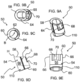
- FIGS. 8A and 8B illustrate two examples of angle pin bushings 50 and 52 constructed according to the teachings of the present disclosure.
- the angle pin bushing 50 defines a generally round or circular slide hole shape for a mold slide.
- the angle pin bushing 52 defines an oblong or oval slide slot shape for a mold slide.
- FIGS. 9A-9E illustrate various view of the angle pin bushing 50, which is described in detail. Other than the oblong or oval shape of the body and slot, the description is equally applicable to the angle pin bushing 52.
- the angle pin bushing 50 has a generally cylinder-shaped body 54 with an outer or exterior surface 56, a top end or face 58, and a bottom end or face 60.
- a bore 62 extends completely through the body 54 in a lengthwise direction and thus opens to both the top face 58 and bottom face 60.
- the bore in this example is generally round or circular, though it may not be precisely circular, as discussed below with regard the saddle geometry shape.
- the bottom face 60 is generally flat or planar and is oriented orthogonal or perpendicular to an axis B of the bore 62.
- the top face 58 is oriented at an angle relative to the axis B such that the top face is not parallel to the bottom face 60 and is not perpendicular to the bore axis.
- a thin or narrow slit 64 is formed lengthwise along and through the body 54 from the outer surface 56 to the bore 62. The slit 64 forms a break in the circumference of the body 54.
- the body 54 has a scalloped or reduced thickness region 68 formed in the outer surface 56 on the front of the body 54 from the top face 58 and terminating partway along the length of the body.
- the terminus or end of the scalloped region 68 defines a step 70 on the front of the angle pin bushing 50.
- the angle pin bushing 52 has substantially the same structure in this example. However, the angle pin bushing 52 has a body 72 that is substantially oval or oblong in configuration instead of being substantially round. Further, the angle pin bushing 52 has a bore 74 with an oval or oblong shape as well to create the above-described lost motion delay, if desired.
- the other features of the angle pin bushing 52 are essentially the same as the angle pin bushing 50 and thus are depicted using the same reference numbers in the drawings.
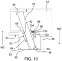
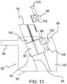
- a mold and slide arrangement i.e., a mold slide
- the mold again has a first half (not shown) and a second half 42, i.e., a mold part, that carries the angle pin 28.
- the mold halves are movable relative to one another in the direction of the arrows MC/MO, as described earlier.
- the mold also has a slide part, i.e., a slide 80 having a body 82 and a coring element 84.
- the slide 80 further has a hole 86 with a generally round or circular cross section shape.
- the hole 86 is formed at an angle through the body 82 or in other words is not perpendicular to the top and bottom surfaces 88, 90 of the body nor to the movement or slide direction S.
- the disclosed angle pin bushing 50 is received within the hole 86.
- the angle pin bushing 50 is received within a pocket 92, i.e., a larger diameter section of the hole 86 at one end of the hole in the slide part.
- the bottom face 60 of the angle pin bushing 50 is borne against a shoulder 94 or ledge at the depth or terminus of the pocket, i.e., where the larger diameter pocket 92 terminates within the hole 86.
- the shoulder 94 stops further insertion of the angle pin bushing 50 into the hole and thus properly positions the angle pin bushing at the desired depth within the hole in the slide 80.
- the angled top face 58 is oriented at the same angle relative to the axis B of the bore 62 as the angle of the hole 86 relative to the orientation of the slide 80 and slide direction S.
- the top face 58 lies flush with the top surface 88 on the body 82 of the slide 80.
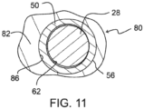
- the phrase"saddle geometry generally refers to the contact area between the angle pin and the bushing surfaces.
- the radius at the contact sides of the angle pin bushing bore is essentially the same as the angle pin catalog size.
- Actual angle pins are about 0.0254mm (i.e. 0.001 inch) undersized of the catalog size.
- the bushing will have a 0.0127mm (i.e. 0.0005) clearance on the functional radii, i.e. the saddle or pin to bushing contact area.
- this radius is carried about 90 degrees (45 degrees in each direction from the mid-plane of the bushing at each contact side.
- there is a 90 degree sweep of radius that is within 0.0127mm (i.e. 0.0005 inches) of the angle pin diameter.
- the retention clip 96 is sized and shaped to fit within a void in the body 82 of the slide 80 created by the clip recess 98 in the body and the scalloped region 68 on the angle pin bushing 50.
- the retention clip 96 is borne against both the step 70 on the angle pin bushing 50 and the ledge 100within the pocket 92.
- a fastener such as a screw 102, can be inserted through a hole 104 in the retention clip 96 and engage a threaded bore 106 in the clip recess 98 to secure the retention clip 96 in place.
- the angle pin bushing 52 with the slot shaped bore 74 can be secured in the same manner but in a slide modified to accommodate the oval or oblong shape of the body 72.
- the sizes and shapes of the clip recess 98 in the slide body 82, the scalloped region 68 on the front of the angle pin bushing 50 or 52, and the retention clip 96 can vary considerably and yet function as intended. However, these components and aspects of the mold tool should be cooperatively shaped to accommodate one another.
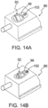
- FIGS. 14A and 14B show the angle pin bushings 50 and 52 installed in corresponding slides. Both the retention clips 96 and the angle pin bushings 50, 52 can be flush with the top surfaces 88 of the slides when the slide is assembled.
- the disclosed angle pin bushings 50 and 52 as shown and described herein provide improvements over conventional angle pin methods. Additionally, the installation and retention of the disclosed angle pin bushings 50 and 52 are also novel. As noted below, the angle pin bushings 50 and 52 can be made from different materials and thus the angle pin contact surfaces within the slide bodies are not limited to the material of the slide body, as in the prior art. The material of choice for the angle pin bushing 50 and 52 can be selected for maximizing the wear properties, cost, durability, friction characteristics, replacement schedule, and the like in view of a given mold application. The disclosed angle pin bushings 50 and 52 are installed into a matching angled pocket within the hole or slot of the slide component or part. The sizes and shapes of the pockets in the slides and the bushing bodies 54 and 72 can vary considerably from the disclosed examples, depending on the needs of a given mold application.
- the pocket shoulder 94 in the slide body 54 or 72 limits the installation depth of the angle bushings 50 and 52 into the hole 86 or slot of the slide to a predetermined level.
- the angle pin bushings 50 and 52 in the disclosed examples have the two flat timing surfaces 66 on the opposite sides of the body 54 or 72. These surfaces or flats 66 orient the angle pin bushing 50 or 52 about its longitudinal axis so that the bushing geometry will align with the hole 86 or slot in the corresponding slide body. Thus, the angle pin bushings 50 and 52 can be precisely aligned with the mold angle pin 28.
- the flat surfaces 66 and the installation depth of the angle pin bushings 50 and 52 can be configured so that the bushing top face 58 is flush with the top surface 88 of a slide 80 or the like when installed.
- the flat surfaces 66 may be wider on the angle pin bushing 52 because of the oval or oblong shape of the body 72.
- the angle pin bushings 50 and 52 as described herein may be fabricated of a highly wear resistant metal, such as bronze, aluminum bronze, or other suitable metal bearing materials. Such bushings could include a coating and/or lubricant at least on the inner surface of the respective bores 62 or 74 to minimize frictional heat build-up and allow for smooth operation. A product manufactured from these materials would be readily adopted by the industry due to the familiarity the industry has with these types of common materials. However, the disclosed angle pin bushing geometry now broadens the consideration and scope of materials that may be used to fabricate the angle pin bushings 50 and 52.
- angle pin bushings 50 and 52 would not require any lubrication, would be naturally wear resistant to enhance the unique and novel geometry, and would perform in all current molding environments.
- such an alternative material would be a wear resistant fabric/resin composite with a resin system capable of performing within the wide-ranging environments as seen in production manufacturing.
- the disclosed angle pin bushings 50 and 52 are essentially bushings, and some standard bushings are used for other purposes in injection molds.
- standard bushings are typically designed with an intentional interference press fit into their respective openings.
- standard bushings typically require the assistance of a press, typically fitted with a hydraulic cylinder that can produce several tons of pressure, to be fit or inserted. This is necessary, as the standard bushings are intentionally oversized on their outside diameter creating the interference fit with the mating hole geometry in the mold tool. This process is relatively simple in nature, as the bushing and receiving bore are axially vertical relative to the mold tool surfaces and the initial contact between bushing and orifice is parallel to each other.
- the first such optional feature is a lead-in relief section 110 at the base of the angle pin bushing body 54 or 72, i.e., adjacent the bottom face 60.
- the relief section 110 is tilted and thus not perpendicular to the bottom face 60 of the angle pin bushing 50 or 52.
- the taper angle of the relief section 110 can be the same as the angle ⁇ of the hole 86 or slot in the slide body.
- the relief section 110 can also be slightly chamfered such that the relief section is engineered to readily fit in the hole 86 or slot and to maintain a line of surface intersection between the relief section and the axial outer profile of the bushing that is parallel with the receiving angle of the installation pocket 92.
- the second such optional feature is the narrow slit 64 provided along the length of the angle pin bushings 50 and 52 and located specifically within one of the two flat timing surfaces 66.
- the slit 64 is engineered to allow the angle pin bushing 50 or 52 to have a minimal amount of deflection during installation.
- the placement of the slit 64 is intentionally located away from the working surfaces, i.e., the inner front and rear pin contact surfaces, of the angle pin bushings 50 and 52. The positioning is such that the bushings can perform as intended while allowing installation without the need for excess force that could damage the bushing during this process.
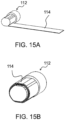
- the novel geometry of the angle pin bushing 50 or 52 may be created with unique mandrels, such as a mandrel 112 as depicted in FIG. 15A .
- the mandrel 112 can be precisely shaped to form the internal bushing geometry.
- the fabric/resin composite material 114 can be wrapped around the mandrel to yield a bushing body 54 having the desired thickness.
- the composite material substrate 114 can be oriented in a way that mates the functional surface in direct contact with the appropriate size angle pin thereby maximizing the wear resistance properties of the composite.
- Outer surface features, such as the slit 66 and the scalloped region 68 and step 70 can be machined in the bushing body after the composite material 114 is formed to the mandrel 112.
- angle pin bushings 50 and 52 have largely been described as beneficial to the mold processing community (molders of plastic parts), the mold tool building community (machinists who build the tooling) would also benefit from the availability and implementation of the angle pin bushings constructed of either a wear resistant metal alloy or fabric/resin composite. As earlier described, there can be significant force required to move a slide. That force may necessitate the fabrication of the slide parts themselves from what is normally referenced as a tool steel alloy.
- the angle pin bushing acting as the bearing surface for the force to move the slide allows alternate materials, such as certain stainless steels, aluminum, and others, to be considered for use as a mold tool slide.
- Tool steel alloys are more expensive per 0.45Kg (i.e. per pound), generally require more time to initially machine, and necessitate heat treatment to maximize the alloy properties. While the heat treatment process adds expense and time, the greater expense comes from the secondary machining operations required to form the parts. Further, heat treatment alters the molecular structure of the alloy. This alteration in molecular structure is known to the mold tool building community and is factored in during the initial machining process prior to having the heat treatment service performed. To summarize, tool steel alloys are machined the first time leaving excess steel that allows for warp and dimensional change that occurs during the heat treatment process.
- the disclosed angle pin bushings 50 and 52 broaden the scope of materials to be considered for use as slide body components, not only in the conventional sense with current materials and manufacturing practices, but further to include evolving materials and processes.
- the mold slides can include 3D printed components and new material combinations that may be developed to enhance molding but may not be well suited for a load bearing surface to interface with an angle pin during mold operation. Again, the heat treatment process adds expense and delay as this is typically a specialty service.
- the mold angle pin 28 will engage the disclosed angle pin bushings 50 or 52 in such a way that the pin will try to extract the bushing from the receiving pocket 92 during mold half separation and then reversibly drive the bushing deeper into the pocket as the mold halves close.
- the shoulder 94 on the pocket bottom prevents the angle pin bushing 50 or 52 from being forcibly pushed through the slide component as the mold halves close.
- the engineered retention clip 96 holds the angle pin bushing 50 or 52 in place while providing solid support at the top of the bushing as the angle pin exits the bushing.
- the disclosed clip geometry provides support behind the force receiving surface area of the angle pin bushing 50 or 52.
- the disclosed angle pin bushing pocket 92 and retention clip recess 98 are disposed at matching angles to the hole 86 or slot in the slide component, such as the slide 80, so that the pocket and recess depths are easily achieved and so that the pocket surfaces are parallel to the angle of the hole or slot, allowing a single set up regardless of the machine tool being used.
- angle pin bushing location and installation method within the slide parts yields benefits for both the molder and mold builder.
- the location of the angle pin bushing 50 or 52 ensures that, as the angle pin 28 engages the bushing, the necessary force to function the slide motion is nearer to the proximal end of the angle pin, i.e., closer to the mounting opening 46 where the angle pin is supported in the second mold half 42.
- a portion of the working end 48 of the angle pin extends through the angle pin bushing 50 or 52 and into the available clearance space or portion of the hole 86 below or beyond the angle pin bushing and the pocket 92.
- angle pin holes are required to be smooth along the entire depth of the hole. Creating a smooth and straight hole through a deep slide is limited to special equipment such as a Gun Drill. Gun Drilling is most often performed by a unique service provider who specializes in the Gun Drilling process. This now requires that the slide be shipped to the service provider, adding significant expense and delay for the mold builder.
- the disclosed angle pin bushings 50 and 52 allow for conventional drilling of clearance through a deep slide without concern for the surface finish of the hole through the entirety of the slide angle pin hole geometry.
- the angle pin bushing 50 or 52 provide smooth functional surfaces and the necessary machining of the hole 86 and the receiving pocket 92 in the slide is easily accomplished with conventional machine tool equipment.
- the angle pin hole 86 (or slot) in the slide 80, the angle pin bushing 50 (or 52), and the angle pin bore 62 (or 74) are each formed having axes that are at least oriented parallel with one another, if not concentric with one another.
- the retention clip 96 abuts against the step 70 on the angle pin bushing 50 (or 52) and is thus received in a portion of the pocket 92, as well as the clip recess 98.
- the retention clip screw hole 104, the threaded bore 106 in the slide 80, and the screw 102 retain the angle pin bushing 50 (or 52) within the hole 86 (or slot) and are installed in a direction parallel with the angle pin hole.
- the retention clip 96, screw hole 104, threaded bore 106, and screw 102 also each have axes that are at least parallel with each other and parallel with the axes of the angle pin hole 86 (or slot), angle pin bushing 50 (or 52), and angle pin bore 62 (or 74). In this arrangement, all of these various axes are parallel with the axis of the angle pin hole 86 (or slot).
- all the various surfaces and holes can be formed without having to reposition the slide 80 to another angle to form the bushing pocket 92 and retainer clip recess 98.
- angle pin hole 86 can be drilled, the bushing pocket 92 can be formed, the clip recess 98 for the retention clip 96 can be formed, and the screw hole 104 and threaded bore 106 for the retention clip 96 clip can be drilled, all along the same axis angle, without having to reorient the slide 80.
- This geometry thus simplifies the fabrication process while still offering the many benefits of utilizing the disclosed angle pin bushings.
- the angle pin 28 is oriented at a desired angle to create a desired amount of movement of the slide 80 in one direction as the second mold part 42 is moved in a different direction.
- the slide 80 may move in a horizontal direction, back and forth, depending on whether the mold is opened or closed.
- the mold part 42 may move in a vertical direction, up and down, perpendicular to the slide movement direction. Other varied relative movement directions are possible as well.
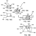
- angle pin bushing 120 is split into two separate bushing parts 122a and 122b.
- Each part 122a and 122b has a bearing face 124, which face one another, and which define the saddle geometry of the bushing 120.
- Each bushing part 122a and 122b has a separate fastener hole 126 for securing the angle pin bushing 120 in an angled pocket of a slide.
- the parts 122a and 122b may be tapered in height across the angle pin bushing 120 so that an angled pocket, similar to the prior examples, can be used in the slide, leaving the top faces flush with the slide and the bearing surfaces oriented at the angle of the angle pin.
- FIGS. 17A-17C show another alternative example of an angle pin bushing 130.
- the angle pin bushing 130 has a rectangular body 132 that includes four fastener holes 134 surrounding an angle pin bore 136 for securing the angle pin bushing in a rectangular pocket of a slide.
- the angle pin busing 130 may otherwise be similar to the prior described angle pin bushing 50, 52 examples.
- FIGS. 18A-18C show another alternative example of an angle pin bushing 140.
- the angle pin bushing 140 again has a rectangular body 142, but instead includes only two fastener holes 144 adjacent a front side of an angle pin bore 146 for securing the angle pin bushing in a rectangular pocket of a slide.
- the angle pin bushing 140 may otherwise be similar to the prior described angle pin bushing 50, 52, 130, examples.
- FIGS. 19A-19C show another alternative example of an angle pin bushing 150.
- the angle pin bushing 150 again has a rectangular body 152 with two fastener holes 154 adjacent a front side of an angle pin bore 156 for securing the angle pin bushing in a rectangular pocket of a slide.
- a top face 158 and a bottom face 160 of the body 152 are parallel to one another.
- the angle pin bore 156 is oriented at the angle of the angle pin relative to the orientation of the top face 158.
- FIGS. 19A-19C show another alternative example of an angle pin bushing 150.
- the angle pin bushing 150 again has a rectangular body 152 with two fastener holes 154 adjacent a front side of an angle pin bore 156 for securing the angle pin bushing in a rectangular pocket of a slide.
- a top face 158 and a bottom face 160 of the body 152 are parallel to one another.
- the angle pin bore 156 is oriented at the angle of the angle pin relative to the orientation of the top
- each of the alternative angle pin bushings 120, 130, 140, and 150 eliminates the retention clip, retention screw, and clip recess in favor of using fasteners to directly retain the bodies of the angle pin bushings in the slide pockets.
- the leader pins When assembled in the closed position, the leader pins are typically aligned within holes and standard bushings located on the "B" side.
- the angle pins would then also be on the"A" side of the mold and would align with the holes or slots in the slide parts.
- the slides may typically move toward one another and as the mold closes.
- the size and productivity of the mold tool can vary widely, depending on the size and complexity of the parts, and thus the mold cavities.
- a mold can be a four-cavity tool with two opposing slides.
- the mold can have a dozen or more cavities and numerous complex slides.
- the mold tools can be on the order of hundreds of 0.45Kgs (i.e. hundreds of pounds) or can be on the order of thousands of 0.45Kgs (i.e. thousands of pounds).
- the disclosed angle pin bushings are not intended to be limited to any particular mold type, size, or arrangement.
Landscapes
- Engineering & Computer Science (AREA)
- Manufacturing & Machinery (AREA)
- Mechanical Engineering (AREA)
- Moulds For Moulding Plastics Or The Like (AREA)
Claims (20)
- Gießschieber, umfassend:ein Schieberteil (80), das einen Schieberkörper (82) aufweist, der entlang einer ersten Richtung bewegbar ist, wobei der Schieberkörper (82) ein Winkelstiftloch (86) aufweist, das darin ausgebildet ist und eine Achse definiert;ein Gießteil (42), das zu dem das Schieberteil (80) benachbart ist und relativ zu dem Schieberteil (80) entlang einer zweiten Richtung bewegbar ist, die sich von der ersten Richtung unterscheidet; undeinen Winkelstift (28), der an dem Gießteil (42) getragen ist;wobei die erste Richtung und die zweite Richtung jeweils nicht parallel zu der Achse des Winkelstiftlochs (86) sind;dadurch gekennzeichnet, dass:das Winkelstiftloch (86) an einem Ende davon eine Tasche (92) aufweist;wobei eine Winkelstiftbuchse (50, 52) in der Tasche (92) sitzt und eine Winkelstiftbohrung (62, 74) definiert, die parallel zu der Achse des Winkelstiftlochs (86) ist; undein Abschnitt des Winkelstifts (28) in dem Gießteil (42) positioniert und zusammen mit diesem relativ zu der Winkelstiftbohrung (62, 74) in der Winkelstiftbuchse (50, 52) bewegbar ist, um das Schieberteil (80) entlang der ersten Richtung zu bewegen.
- Gießschieber nach Anspruch 1, wobei das Schieberteil (80) und das Gießteil (42) Teil eines Spritzgießwerkzeugs sind.
- Gießschieber nach Anspruch 1, wobei die zweite Richtung senkrecht zu der ersten Richtung ist.
- Gießschieber nach Anspruch 1, wobei der Winkelstift (28) parallel zu der Achse des Winkelstiftlochs (86) ausgerichtet ist und wobei die Achse in einem Winkel von mehr als 0 Grad und weniger als 90 Grad relativ zu der ersten und der zweiten Richtung ausgerichtet ist.
- Gießschieber nach Anspruch 1, wobei das Winkelstiftloch (86) über eine kreisförmige Querschnittsform verfügt.
- Gießschieber nach Anspruch 5, wobei die Winkelstiftbohrung (62, 74) der Winkelstiftbuchse (50, 52) über eine im Allgemeinen kreisförmige Querschnittsform verfügt.
- Gießschieber nach Anspruch 1, wobei das Winkelstiftloch (86) ein Schlitz ist, der eine nicht runde ovale oder längliche Querschnittsform aufweist.
- Gießschieber nach Anspruch 7, wobei die Winkelstiftbohrung (62, 74) der Winkelstiftbuchse (50, 52) ein Schlitz ist, der eine nicht runde ovale oder längliche Querschnittsform aufweist.
- Gießschieber nach Anspruch 1, wobei die Tasche (92) eine größere Breite als ein Rest des Winkelstiftlochs (86) aufweist und eine Schulter (94) an einem Ende der Tasche (92) benachbart zu dem Rest des Winkelstiftlochs (86) definiert und wobei die Winkelstiftbuchse (50, 52) innerhalb der Tasche (92) an der Schulter (94) anliegt.
- Gießschieber nach Anspruch 9, wobei die Winkelstiftbuchse (50, 52) eine obere Fläche (58) aufweist, die bündig und parallel zu einer oberen Fläche (88) des Schieberteils (80) ist, die das Winkelstiftloch (86) umgibt.
- Gießschieber nach Anspruch 1, wobei die Winkelstiftbuchse (50, 52) an einem Abschnitt einer äußeren Oberfläche (56) davon eine ausgekehlte Region (68) aufweist, wobei die ausgekehlte Region (68) eine Stufe (70) an der äußeren Oberfläche (56) definiert.
- Gießschieber nach Anspruch 11, wobei eine Klammeraussparung (98) benachbart zu der Tasche (92) ausgebildet ist und eine Tiefe aufweist, die der Position der Stufe (70) entspricht, und wobei eine Halteklammer (96) innerhalb der Klammeraussparung (98) aufgenommen und gehalten ist und an die Stufe (70) angrenzt, um die Winkelstiftbuchse (50, 52) innerhalb der Tasche (92) des Winkelstiftlochs (86) zu halten.
- Gießschieber nach Anspruch 1, wobei die Winkelstiftbuchse (50, 52) aus einem Gewebe-/Harz-Verbundmaterial ausgebildet ist.
- Gießschieber nach Anspruch 1, wobei die Winkelstiftbuchse (50, 52) einen langgestreckten Schlitz (64) aufweist, der entlang einer Länge der Winkelstiftbuchse (50, 52) und durch die Winkelstiftbuchse von einer äußeren Oberfläche (56) zu der Winkelstiftbohrung (62, 74) ausgebildet ist.
- Gießschieber nach Anspruch 1, wobei die Winkelstiftbuchse (50, 52) eine flache Oberflächenregion aufweist, die an einer äußeren Oberfläche (56) an jeder von gegenüberliegenden Seiten der Winkelstiftbuchse (50, 52) ausgebildet ist.
- Gießschieber nach Anspruch 1, wobei die Winkelstiftbuchse (50, 52) an einem Ende davon einen Einführungsentlastungsbereich (110) aufweist, wobei der Einführungsentlastungsbereich (110) eine Abschrägung an einer unteren Oberfläche des Schieberkörpers (82) einschließt.
- Gießschieber nach Anspruch 1, wobei die Achse des Winkelstiftlochs (86), der Winkelstiftbohrung (62, 74) der Winkelstiftbuchse (50, 52) und des Winkelstifts (28) jeweils konzentrisch zueinander ausgerichtet sind.
- Gießschieber nach Anspruch 17, wobei eine Halteklammer (96) in einer Klammeraussparung (98) benachbart zu der Tasche (92) aufgenommen ist und an eine Stufe (70) an der Winkelstiftbuchse (50, 52) angrenzt, wobei ein Befestigungselementloch (126) durch die Halteklammer (96) und eine Befestigungselementbohrung in dem Schieberkörper (82) ein Befestigungselement (102) aufnehmen, das die Winkelstiftbuchse (50, 52) innerhalb der Tasche (92) hält, und wobei das Befestigungselementloch (126) und die Befestigungselementbohrung auch jeweils eine Achse aufweisen, die mindestens parallel zu der Achse des Winkelstiftlochs (86) ist.
- Winkelstiftbuchse (50, 52) für einen Gießschieber (80), dadurch gekennzeichnet, dass die Winkelstiftbuchse Folgendes umfasst:einen Körper (54, 72), der eine äußere Oberfläche (56) aufweist, die sich zwischen einer oberen Fläche (58) und einer unteren Fläche (60) erstreckt;eine Winkelstiftbohrung (62), die durch den Körper (54, 72) zwischen der oberen Fläche (58) und der unteren Fläche (60) ausgebildet ist;wobei die obere Fläche (58) und eine Achse der Winkelstiftbohrung (62) nicht senkrecht zueinander sind.
- Winkelstiftbuchse nach Anspruch 19, wobei die obere Fläche (58) nicht parallel zu der unteren Fläche (60) ist, wobei die Winkelstiftbohrung (62) senkrecht zu der unteren Fläche (60) ist und wobei der Körper (54, 72) aus einem Gewebe-/Harz-Verbundmaterial ausgebildet ist.
Applications Claiming Priority (2)
| Application Number | Priority Date | Filing Date | Title |
|---|---|---|---|
| US201862718470P | 2018-08-14 | 2018-08-14 | |
| PCT/US2019/046572 WO2020037081A1 (en) | 2018-08-14 | 2019-08-14 | Angle pin bushing and injection mold slide having same |
Publications (4)
| Publication Number | Publication Date |
|---|---|
| EP3837101A1 EP3837101A1 (de) | 2021-06-23 |
| EP3837101A4 EP3837101A4 (de) | 2022-05-11 |
| EP3837101B1 true EP3837101B1 (de) | 2024-10-09 |
| EP3837101C0 EP3837101C0 (de) | 2024-10-09 |
Family
ID=69524425
Family Applications (1)
| Application Number | Title | Priority Date | Filing Date |
|---|---|---|---|
| EP19849769.5A Active EP3837101B1 (de) | 2018-08-14 | 2019-08-14 | Winkelstiftbuchse und spritzgiessschieber damit |
Country Status (7)
| Country | Link |
|---|---|
| US (2) | US12049034B2 (de) |
| EP (1) | EP3837101B1 (de) |
| JP (2) | JP7434284B2 (de) |
| CA (1) | CA3109469A1 (de) |
| ES (1) | ES2993813T3 (de) |
| MX (2) | MX2021001785A (de) |
| WO (1) | WO2020037081A1 (de) |
Families Citing this family (2)
| Publication number | Priority date | Publication date | Assignee | Title |
|---|---|---|---|---|
| CN114734586A (zh) * | 2022-03-11 | 2022-07-12 | 精英模具(珠海)有限公司 | 注塑模具的防擦烧结构 |
| CN114953365B (zh) * | 2022-07-29 | 2022-09-30 | 赫比(成都)精密塑胶制品有限公司 | 模具结构 |
Citations (2)
| Publication number | Priority date | Publication date | Assignee | Title |
|---|---|---|---|---|
| JPH0985786A (ja) * | 1995-09-27 | 1997-03-31 | Olympus Optical Co Ltd | アンダーカット処理金型 |
| EP2553286B1 (de) * | 2010-03-29 | 2016-11-30 | H.E.F. | Selbstschmierende buchse für ein gelenk zur montage auf einem schaft |
Family Cites Families (32)
| Publication number | Priority date | Publication date | Assignee | Title |
|---|---|---|---|---|
| US3516302A (en) * | 1968-07-15 | 1970-06-23 | Vincent H Muttart | Ejector pin retraction mechanism for molding operation |
| US4009979A (en) * | 1974-06-26 | 1977-03-01 | Master Unit Die Products, Inc. | Molding die apparatus |
| US4052033A (en) * | 1976-09-29 | 1977-10-04 | Pixley Richards West, Inc. | Ejector pin retracting means for plastic molding dies |
| SE8203023L (sv) * | 1981-05-21 | 1982-11-22 | Volvo Penta Ab | Forfarande vid framstellning av en batdel samt genom forfarandet framstelld del |
| US4502660A (en) * | 1983-11-21 | 1985-03-05 | Luther Leroy D | Mold including side walls with locking projections |
| US4828480A (en) * | 1986-10-22 | 1989-05-09 | Smith Kenneth J | Sprue bushing with automatically activated gate |
| US4765585A (en) * | 1987-02-27 | 1988-08-23 | Superior Die Set Corporation | Slide retainer for injection molds |
| US4768747A (en) * | 1987-07-31 | 1988-09-06 | Williams John B | Slide clip |
| US5880043A (en) * | 1991-04-03 | 1999-03-09 | Hoechst Aktiengesellschaft | Fiber-reinforced material and production and use thereof |
| US5167898A (en) * | 1992-03-05 | 1992-12-01 | Triangle Tool Corporation | Injection mold assembly and method for manufacturing a plastic tub with holes |
| US5234329A (en) * | 1992-10-02 | 1993-08-10 | Vandenberg Leo A | Angle pin assembly |
| US5407344A (en) | 1993-07-12 | 1995-04-18 | Lake Center Industries, Inc. | Single direction cam for insert molding machine |
| US5882695A (en) * | 1996-02-09 | 1999-03-16 | D & L Incorporated | Demountable mold pin and bushing system and replaceable bushings therefor |
| US6398541B1 (en) * | 1997-06-13 | 2002-06-04 | Incoe Corporation | Injection molding shut-off bushing with separate material flow path |
| US6364654B1 (en) * | 1999-10-06 | 2002-04-02 | Luther Leroy D. | Mold assembly for manufacturing a plastic tub with holes |
| ES2203261B1 (es) * | 2000-05-23 | 2005-06-16 | Alberto Navarra Pruna | Retentor para correderas de moldes de inyeccion de plasticos. |
| US6877974B2 (en) * | 2000-12-22 | 2005-04-12 | Acushnet Company | Split vent pin for injection molding |
| US6431852B1 (en) * | 2001-02-02 | 2002-08-13 | Leo A. Vandenberg | Internal latch for an injection mold |
| DE60115964T2 (de) * | 2001-07-27 | 2006-08-24 | Freni Brembo S.P.A., Curno | Form und verfahren zur herstellung eines mit kühlöffnungen versehenen bremsbelages aus verbundwerkstoff |
| US20030146551A1 (en) * | 2002-02-01 | 2003-08-07 | Weeks Bruce V. | Blow-molding large, relatively thick-walled, thermoplastic resin products |
| JP3846448B2 (ja) * | 2002-04-19 | 2006-11-15 | 通則 竹元 | スライドコアユニット |
| US7387505B1 (en) * | 2006-11-24 | 2008-06-17 | Cheng Uei Precision Industry Co., Ltd. | Side-action mechanism and injection mold using the same |
| US8113812B2 (en) | 2007-07-17 | 2012-02-14 | Mold-Masters (2007) Limited | Valve pin bushing assembly for an injection molding apparatus |
| US7628605B2 (en) * | 2007-07-20 | 2009-12-08 | Husky Injection Molding Systems Ltd. | Mold stack |
| US8038425B2 (en) * | 2008-04-21 | 2011-10-18 | Progressive Components International Corporation | Injection mold friction puller |
| IT1410977B1 (it) * | 2010-06-14 | 2014-10-03 | Automobili Lamborghini Spa | Processo e dispositivi per fabbricare prodotti in materiali compositi |
| US20120082752A1 (en) * | 2010-09-30 | 2012-04-05 | Cheng Uei Precision Industry Co., Ltd. | Plastic injection mold |
| US8371842B2 (en) * | 2010-10-27 | 2013-02-12 | Cheng Uei Precision Industry Co., Ltd. | Mold with sliders |
| US8459332B1 (en) * | 2012-07-09 | 2013-06-11 | Kevin M. O'Connor | Piston outer panel mold and method of constructing a piston and forming an undercut cooling gallery of a piston therewith |
| TW201442844A (zh) | 2013-05-10 | 2014-11-16 | Hon Hai Prec Ind Co Ltd | 模具斜梢結構以及注射成型模具 |
| CN104786445B (zh) | 2015-04-20 | 2017-09-26 | 中山市利群精密实业有限公司 | 一种用于塑料模具的行位抽芯结构 |
| US9855675B1 (en) * | 2016-09-20 | 2018-01-02 | RELIGN Corporation | Arthroscopic devices and methods |
-
2019
- 2019-08-14 WO PCT/US2019/046572 patent/WO2020037081A1/en not_active Ceased
- 2019-08-14 ES ES19849769T patent/ES2993813T3/es active Active
- 2019-08-14 JP JP2021507688A patent/JP7434284B2/ja active Active
- 2019-08-14 EP EP19849769.5A patent/EP3837101B1/de active Active
- 2019-08-14 CA CA3109469A patent/CA3109469A1/en active Pending
- 2019-08-14 MX MX2021001785A patent/MX2021001785A/es unknown
- 2019-08-14 US US16/541,075 patent/US12049034B2/en active Active
-
2021
- 2021-02-12 MX MX2025005583A patent/MX2025005583A/es unknown
-
2024
- 2024-02-07 JP JP2024017055A patent/JP7743551B2/ja active Active
- 2024-07-26 US US18/786,153 patent/US20240383180A1/en active Pending
Patent Citations (2)
| Publication number | Priority date | Publication date | Assignee | Title |
|---|---|---|---|---|
| JPH0985786A (ja) * | 1995-09-27 | 1997-03-31 | Olympus Optical Co Ltd | アンダーカット処理金型 |
| EP2553286B1 (de) * | 2010-03-29 | 2016-11-30 | H.E.F. | Selbstschmierende buchse für ein gelenk zur montage auf einem schaft |
Also Published As
| Publication number | Publication date |
|---|---|
| US12049034B2 (en) | 2024-07-30 |
| MX2021001785A (es) | 2021-07-15 |
| US20240383180A1 (en) | 2024-11-21 |
| CA3109469A1 (en) | 2020-02-20 |
| EP3837101A1 (de) | 2021-06-23 |
| EP3837101A4 (de) | 2022-05-11 |
| US20200055222A1 (en) | 2020-02-20 |
| EP3837101C0 (de) | 2024-10-09 |
| JP2024040294A (ja) | 2024-03-25 |
| MX2025005583A (es) | 2025-06-02 |
| ES2993813T3 (en) | 2025-01-09 |
| JP7434284B2 (ja) | 2024-02-20 |
| JP7743551B2 (ja) | 2025-09-24 |
| WO2020037081A1 (en) | 2020-02-20 |
| JP2021534018A (ja) | 2021-12-09 |
Similar Documents
| Publication | Publication Date | Title |
|---|---|---|
| US20240383180A1 (en) | Angle pin bushing and injection mold slide having same | |
| US6872069B2 (en) | Ejector sleeve for molding a raised aperture in a molded article | |
| US6569370B1 (en) | Injection molding system and method using cavity flange and neck ring insert | |
| EP0571102B1 (de) | Zusammenbau gepaarter einander angepasster Gussteile und ihr Herstellungsverfahren | |
| EP2651598B1 (de) | Zum einspannen einer turbinenschaufel eingerichtete einrichtung und turbinenschaufel | |
| US8567228B2 (en) | Tool system with interchangeable tool inserts for punching machines | |
| EP0595061A1 (de) | Strangpressmatrize und Matrizeeinsatz dafür | |
| US9199400B2 (en) | Methods of injection molding an article | |
| JP2007503322A (ja) | 切れ刃を有するドリルボディ及びその製造方法並びにそのドリルボディを備える穴明け工具 | |
| KR102510360B1 (ko) | 공구 헤드의 제조 방법 | |
| US6752616B2 (en) | Dry, lubricated ejector pins | |
| US5882695A (en) | Demountable mold pin and bushing system and replaceable bushings therefor | |
| KR101414110B1 (ko) | 베어링 장치 | |
| US5233738A (en) | Tool for fine machining | |
| EP1857244A1 (de) | Gekühlter Formeinsatz für Spritzwerkzeuge | |
| US7309229B2 (en) | Mold die | |
| EP2796218A1 (de) | Ziehmatrizenwerkzeug und Verfahren zur Herstellung eines solchen Werkzeugs | |
| JPH09141702A (ja) | ディスク射出成形金型の固定側と可動側の円盤キャビティプレートの整列案内装置 | |
| JP7656902B2 (ja) | 成形体 | |
| JP4642686B2 (ja) | 滑り軸受の製造方法 | |
| US10814454B2 (en) | Tool guide for tie bar removal from casting cores | |
| JP2007203719A (ja) | 射出成形用樹脂型及び射出成形用樹脂型の製造方法 |
Legal Events
| Date | Code | Title | Description |
|---|---|---|---|
| STAA | Information on the status of an ep patent application or granted ep patent |
Free format text: STATUS: THE INTERNATIONAL PUBLICATION HAS BEEN MADE |
|
| PUAI | Public reference made under article 153(3) epc to a published international application that has entered the european phase |
Free format text: ORIGINAL CODE: 0009012 |
|
| STAA | Information on the status of an ep patent application or granted ep patent |
Free format text: STATUS: REQUEST FOR EXAMINATION WAS MADE |
|
| 17P | Request for examination filed |
Effective date: 20210308 |
|
| AK | Designated contracting states |
Kind code of ref document: A1 Designated state(s): AL AT BE BG CH CY CZ DE DK EE ES FI FR GB GR HR HU IE IS IT LI LT LU LV MC MK MT NL NO PL PT RO RS SE SI SK SM TR |
|
| DAV | Request for validation of the european patent (deleted) | ||
| DAX | Request for extension of the european patent (deleted) | ||
| REG | Reference to a national code |
Ref country code: DE Ref legal event code: R079 Ipc: B29C0045330000 Ref country code: DE Ref legal event code: R079 Ref document number: 602019060229 Country of ref document: DE Free format text: PREVIOUS MAIN CLASS: B29C0033000000 Ipc: B29C0045330000 |
|
| A4 | Supplementary search report drawn up and despatched |
Effective date: 20220413 |
|
| RIC1 | Information provided on ipc code assigned before grant |
Ipc: B29C 45/33 20060101AFI20220407BHEP |
|
| GRAP | Despatch of communication of intention to grant a patent |
Free format text: ORIGINAL CODE: EPIDOSNIGR1 |
|
| STAA | Information on the status of an ep patent application or granted ep patent |
Free format text: STATUS: GRANT OF PATENT IS INTENDED |
|
| INTG | Intention to grant announced |
Effective date: 20240510 |
|
| GRAS | Grant fee paid |
Free format text: ORIGINAL CODE: EPIDOSNIGR3 |
|
| GRAA | (expected) grant |
Free format text: ORIGINAL CODE: 0009210 |
|
| STAA | Information on the status of an ep patent application or granted ep patent |
Free format text: STATUS: THE PATENT HAS BEEN GRANTED |
|
| AK | Designated contracting states |
Kind code of ref document: B1 Designated state(s): AL AT BE BG CH CY CZ DE DK EE ES FI FR GB GR HR HU IE IS IT LI LT LU LV MC MK MT NL NO PL PT RO RS SE SI SK SM TR |
|
| REG | Reference to a national code |
Ref country code: CH Ref legal event code: EP |
|
| REG | Reference to a national code |
Ref country code: DE Ref legal event code: R096 Ref document number: 602019060229 Country of ref document: DE |
|
| REG | Reference to a national code |
Ref country code: IE Ref legal event code: FG4D |
|
| U01 | Request for unitary effect filed |
Effective date: 20241025 |
|
| U07 | Unitary effect registered |
Designated state(s): AT BE BG DE DK EE FI FR IT LT LU LV MT NL PT RO SE SI Effective date: 20241107 |
|
| REG | Reference to a national code |
Ref country code: ES Ref legal event code: FG2A Ref document number: 2993813 Country of ref document: ES Kind code of ref document: T3 Effective date: 20250109 |
|
| PG25 | Lapsed in a contracting state [announced via postgrant information from national office to epo] |
Ref country code: IS Free format text: LAPSE BECAUSE OF FAILURE TO SUBMIT A TRANSLATION OF THE DESCRIPTION OR TO PAY THE FEE WITHIN THE PRESCRIBED TIME-LIMIT Effective date: 20250209 Ref country code: HR Free format text: LAPSE BECAUSE OF FAILURE TO SUBMIT A TRANSLATION OF THE DESCRIPTION OR TO PAY THE FEE WITHIN THE PRESCRIBED TIME-LIMIT Effective date: 20241009 |
|
| PG25 | Lapsed in a contracting state [announced via postgrant information from national office to epo] |
Ref country code: NO Free format text: LAPSE BECAUSE OF FAILURE TO SUBMIT A TRANSLATION OF THE DESCRIPTION OR TO PAY THE FEE WITHIN THE PRESCRIBED TIME-LIMIT Effective date: 20250109 |
|
| PG25 | Lapsed in a contracting state [announced via postgrant information from national office to epo] |
Ref country code: GR Free format text: LAPSE BECAUSE OF FAILURE TO SUBMIT A TRANSLATION OF THE DESCRIPTION OR TO PAY THE FEE WITHIN THE PRESCRIBED TIME-LIMIT Effective date: 20250110 |
|
| PG25 | Lapsed in a contracting state [announced via postgrant information from national office to epo] |
Ref country code: PL Free format text: LAPSE BECAUSE OF FAILURE TO SUBMIT A TRANSLATION OF THE DESCRIPTION OR TO PAY THE FEE WITHIN THE PRESCRIBED TIME-LIMIT Effective date: 20241009 |
|
| PG25 | Lapsed in a contracting state [announced via postgrant information from national office to epo] |
Ref country code: RS Free format text: LAPSE BECAUSE OF FAILURE TO SUBMIT A TRANSLATION OF THE DESCRIPTION OR TO PAY THE FEE WITHIN THE PRESCRIBED TIME-LIMIT Effective date: 20250109 |
|
| PG25 | Lapsed in a contracting state [announced via postgrant information from national office to epo] |
Ref country code: SM Free format text: LAPSE BECAUSE OF FAILURE TO SUBMIT A TRANSLATION OF THE DESCRIPTION OR TO PAY THE FEE WITHIN THE PRESCRIBED TIME-LIMIT Effective date: 20241009 |
|
| PG25 | Lapsed in a contracting state [announced via postgrant information from national office to epo] |
Ref country code: SK Free format text: LAPSE BECAUSE OF FAILURE TO SUBMIT A TRANSLATION OF THE DESCRIPTION OR TO PAY THE FEE WITHIN THE PRESCRIBED TIME-LIMIT Effective date: 20241009 |
|
| PG25 | Lapsed in a contracting state [announced via postgrant information from national office to epo] |
Ref country code: CZ Free format text: LAPSE BECAUSE OF FAILURE TO SUBMIT A TRANSLATION OF THE DESCRIPTION OR TO PAY THE FEE WITHIN THE PRESCRIBED TIME-LIMIT Effective date: 20241009 |
|
| PLBE | No opposition filed within time limit |
Free format text: ORIGINAL CODE: 0009261 |
|
| STAA | Information on the status of an ep patent application or granted ep patent |
Free format text: STATUS: NO OPPOSITION FILED WITHIN TIME LIMIT |
|
| 26N | No opposition filed |
Effective date: 20250710 |
|
| U20 | Renewal fee for the european patent with unitary effect paid |
Year of fee payment: 7 Effective date: 20250811 |
|
| PGFP | Annual fee paid to national office [announced via postgrant information from national office to epo] |
Ref country code: ES Payment date: 20250901 Year of fee payment: 7 |
|
| PGFP | Annual fee paid to national office [announced via postgrant information from national office to epo] |
Ref country code: GB Payment date: 20250811 Year of fee payment: 7 |