EP3836618A1 - Procédé et appareil de transmission de données, et procédé et appareil de commutation de service - Google Patents
Procédé et appareil de transmission de données, et procédé et appareil de commutation de service Download PDFInfo
- Publication number
- EP3836618A1 EP3836618A1 EP19846735.9A EP19846735A EP3836618A1 EP 3836618 A1 EP3836618 A1 EP 3836618A1 EP 19846735 A EP19846735 A EP 19846735A EP 3836618 A1 EP3836618 A1 EP 3836618A1
- Authority
- EP
- European Patent Office
- Prior art keywords
- terminal
- information
- qos flow
- qos
- sidelink
- Prior art date
- Legal status (The legal status is an assumption and is not a legal conclusion. Google has not performed a legal analysis and makes no representation as to the accuracy of the status listed.)
- Pending
Links
- 230000005540 biological transmission Effects 0.000 title claims abstract description 158
- 238000000034 method Methods 0.000 title claims abstract description 91
- 238000013507 mapping Methods 0.000 claims description 146
- 230000004044 response Effects 0.000 claims description 36
- 230000015654 memory Effects 0.000 claims description 17
- 238000004590 computer program Methods 0.000 claims description 11
- 230000006835 compression Effects 0.000 claims description 4
- 238000007906 compression Methods 0.000 claims description 4
- 230000014759 maintenance of location Effects 0.000 claims description 4
- 230000006978 adaptation Effects 0.000 claims description 2
- 102100022734 Acyl carrier protein, mitochondrial Human genes 0.000 claims 27
- 101000678845 Homo sapiens Acyl carrier protein, mitochondrial Proteins 0.000 claims 27
- XHSQDZXAVJRBMX-UHFFFAOYSA-N 2-(5,6-dichlorobenzimidazol-1-yl)-5-(hydroxymethyl)oxolane-3,4-diol Chemical compound OC1C(O)C(CO)OC1N1C2=CC(Cl)=C(Cl)C=C2N=C1 XHSQDZXAVJRBMX-UHFFFAOYSA-N 0.000 claims 2
- 230000000977 initiatory effect Effects 0.000 claims 2
- 238000004891 communication Methods 0.000 description 32
- 238000010586 diagram Methods 0.000 description 14
- 230000006870 function Effects 0.000 description 8
- 230000007246 mechanism Effects 0.000 description 6
- 238000012935 Averaging Methods 0.000 description 5
- 230000011664 signaling Effects 0.000 description 4
- 238000010295 mobile communication Methods 0.000 description 3
- 238000012986 modification Methods 0.000 description 3
- 230000004048 modification Effects 0.000 description 3
- 238000012545 processing Methods 0.000 description 3
- 238000013506 data mapping Methods 0.000 description 2
- 238000007726 management method Methods 0.000 description 2
- 230000003287 optical effect Effects 0.000 description 2
- 230000008569 process Effects 0.000 description 2
- 238000000275 quality assurance Methods 0.000 description 2
- 238000011160 research Methods 0.000 description 2
- 238000011161 development Methods 0.000 description 1
- 238000005516 engineering process Methods 0.000 description 1
- 230000003993 interaction Effects 0.000 description 1
- 230000007774 longterm Effects 0.000 description 1
Images


Classifications
-
- H—ELECTRICITY
- H04—ELECTRIC COMMUNICATION TECHNIQUE
- H04W—WIRELESS COMMUNICATION NETWORKS
- H04W8/00—Network data management
- H04W8/005—Discovery of network devices, e.g. terminals
-
- H—ELECTRICITY
- H04—ELECTRIC COMMUNICATION TECHNIQUE
- H04W—WIRELESS COMMUNICATION NETWORKS
- H04W28/00—Network traffic management; Network resource management
- H04W28/02—Traffic management, e.g. flow control or congestion control
- H04W28/0231—Traffic management, e.g. flow control or congestion control based on communication conditions
- H04W28/0236—Traffic management, e.g. flow control or congestion control based on communication conditions radio quality, e.g. interference, losses or delay
-
- H—ELECTRICITY
- H04—ELECTRIC COMMUNICATION TECHNIQUE
- H04W—WIRELESS COMMUNICATION NETWORKS
- H04W28/00—Network traffic management; Network resource management
- H04W28/02—Traffic management, e.g. flow control or congestion control
- H04W28/0252—Traffic management, e.g. flow control or congestion control per individual bearer or channel
- H04W28/0257—Traffic management, e.g. flow control or congestion control per individual bearer or channel the individual bearer or channel having a maximum bit rate or a bit rate guarantee
-
- H—ELECTRICITY
- H04—ELECTRIC COMMUNICATION TECHNIQUE
- H04W—WIRELESS COMMUNICATION NETWORKS
- H04W28/00—Network traffic management; Network resource management
- H04W28/02—Traffic management, e.g. flow control or congestion control
- H04W28/0252—Traffic management, e.g. flow control or congestion control per individual bearer or channel
- H04W28/0263—Traffic management, e.g. flow control or congestion control per individual bearer or channel involving mapping traffic to individual bearers or channels, e.g. traffic flow template [TFT]
-
- H—ELECTRICITY
- H04—ELECTRIC COMMUNICATION TECHNIQUE
- H04W—WIRELESS COMMUNICATION NETWORKS
- H04W28/00—Network traffic management; Network resource management
- H04W28/02—Traffic management, e.g. flow control or congestion control
- H04W28/0268—Traffic management, e.g. flow control or congestion control using specific QoS parameters for wireless networks, e.g. QoS class identifier [QCI] or guaranteed bit rate [GBR]
-
- H—ELECTRICITY
- H04—ELECTRIC COMMUNICATION TECHNIQUE
- H04W—WIRELESS COMMUNICATION NETWORKS
- H04W28/00—Network traffic management; Network resource management
- H04W28/16—Central resource management; Negotiation of resources or communication parameters, e.g. negotiating bandwidth or QoS [Quality of Service]
- H04W28/24—Negotiating SLA [Service Level Agreement]; Negotiating QoS [Quality of Service]
-
- H—ELECTRICITY
- H04—ELECTRIC COMMUNICATION TECHNIQUE
- H04W—WIRELESS COMMUNICATION NETWORKS
- H04W36/00—Hand-off or reselection arrangements
- H04W36/02—Buffering or recovering information during reselection ; Modification of the traffic flow during hand-off
-
- H—ELECTRICITY
- H04—ELECTRIC COMMUNICATION TECHNIQUE
- H04W—WIRELESS COMMUNICATION NETWORKS
- H04W36/00—Hand-off or reselection arrangements
- H04W36/03—Reselecting a link using a direct mode connection
-
- H—ELECTRICITY
- H04—ELECTRIC COMMUNICATION TECHNIQUE
- H04W—WIRELESS COMMUNICATION NETWORKS
- H04W4/00—Services specially adapted for wireless communication networks; Facilities therefor
- H04W4/30—Services specially adapted for particular environments, situations or purposes
- H04W4/40—Services specially adapted for particular environments, situations or purposes for vehicles, e.g. vehicle-to-pedestrians [V2P]
-
- H—ELECTRICITY
- H04—ELECTRIC COMMUNICATION TECHNIQUE
- H04W—WIRELESS COMMUNICATION NETWORKS
- H04W76/00—Connection management
- H04W76/10—Connection setup
- H04W76/14—Direct-mode setup
-
- H—ELECTRICITY
- H04—ELECTRIC COMMUNICATION TECHNIQUE
- H04W—WIRELESS COMMUNICATION NETWORKS
- H04W92/00—Interfaces specially adapted for wireless communication networks
- H04W92/16—Interfaces between hierarchically similar devices
- H04W92/18—Interfaces between hierarchically similar devices between terminal devices
Definitions
- the present application relates to the field of communication, for example, to a data transmission method and apparatus and a traffic switch method and apparatus.
- vehicle to everything refers to a large system network for wireless communication and information exchange between a vehicle and X (X: a vehicle, a pedestrian, an infrastructure, the Internet, or the like) in accordance with an agreed communication protocol and a data interaction standard.
- the vehicle-to-everything communication ensures the driving safety of the vehicle, improves the transport efficiency, and provides the vehicle with convenience or entertainment information.
- the vehicle-to-everything communication includes three different types: vehicle-to-vehicle (V2V) communication, vehicle-to-infrastructure/vehicle-to-network (V2I/V2N) communication, and vehicle-to-pedestrian (V2P) communication.
- V2V vehicle-to-vehicle
- V2I/V2N vehicle-to-infrastructure/vehicle-to-network
- V2P vehicle-to-pedestrian
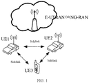
- FIG. 1 is a schematic diagram of a V2X sidelink traffic scenario in the related art.
- FIG. 1 shows a base station, UE1, UE2, and UE3, and sidelink traffic transmission is performed among the three terminals.
- V2X communication method based on a sidelink between user equipments is one way of implementing V2X standards. That is, traffic data is directly transmitted from a source user equipment to a target user equipment via an air interface without being forwarded by a base station and a core network.
- V2X communication method as shown in FIG. 1 , is simply referred to as PC5-based V2X communication or V2X sidelink communication.
- V2X traffic is mainly divided into four categories: vehicle platooning, extended sensors, advanced driving (semi-automated or full-automated driving), and remote driving.
- Performance requirements to be met are as follows: a packet size supporting 50 bytes to 12000 bytes, a transmission rate of 2 messages to 50 messages per second, a maximum end-to-end delay of 3 ms to 500 ms, a reliability of 90% to 99.999%, a data rate of 0.5 Mbps to 1000 Mbps, and a transmission range supporting 50 m to 1000 m.
- 3GPP has approved the research of vehicle-to-everything communication based on 5th Generation (5G) including vehicle-to-everything communication based on a 5G air interface and vehicle-to-everything communication based on a 5G sidelink.
- 5G 5th Generation
- a data transmission method and apparatus and a traffic switch method and apparatus are provided in the embodiments of the present application to solve at least the problem in the related art of lacking solutions of determining sidelink service quality assurance and a bearer suitable for the new radio.
- a data transmission method includes: a first terminal acquiring first information of quality of service (QoS) of a to-be-transmitted data packet on a sidelink; configuring a sidelink bearer; and mapping, according to the first information, the to-be-transmitted data packet to the sidelink bearer for transmission to a second terminal.
- QoS quality of service
- a traffic switch method is further provided according to another embodiment of the present application.
- the method includes: a first terminal acquiring traffic switch information; and performing traffic switch according to the traffic switch information, where the traffic switch is configured for switching a to-be-transmitted data packet between a Uu interface and a PC5 interface.
- a data transmission apparatus is further provided according to another embodiment of the present application.
- the apparatus includes: a first acquisition module configured to acquire first information of quality of service (QoS) of a to-be-transmitted data packet on a sidelink, a first configuration module configured to configure a sidelink bearer, and a first mapping module configured to map, according to the first information, the to-be-transmitted data packet to the sidelink bearer for transmission to a second terminal.
- QoS quality of service
- a traffic switch apparatus is further provided according to another embodiment of the present application.
- the apparatus includes: a second acquisition module configured to enable a first terminal to acquire traffic switch information and a second switch module configured to perform traffic switch according to the traffic switch information, where the traffic switch is configured for switching a to-be-transmitted data packet between a Uu interface and a PC5 interface.
- a storage medium is further provided according to another embodiment of the present application.
- the storage medium stores a computer program.
- the computer program is configured to, when executed, perform the steps of any one of the foregoing method embodiments.
- An electronic apparatus is further provided according to another embodiment of the present application, and includes a memory and a processor.
- the memory stores a computer program and the processor is configured to execute the computer program to perform the steps of any one of the foregoing method embodiments.
- the first terminal acquires the first information of the quality of service (QoS) of the to-be-transmitted data packet on the sidelink, configures the sidelink bearer, and maps, according to the first information, the to-be-transmitted data packet to the sidelink bearer for transmission to the second terminal.
- QoS quality of service
- sidelink traffic transmission is performed according to the first information related to QoS. Solutions of sidelink quality of service assurance and bearer configuration and mapping suitable for the new radio are provided, solving the problems in the related art of lacking solutions of sidelink quality of service assurance and determination of a sidelink bearer suitable for the new radio.
- Embodiments of the present application provide a mobile communication network (including a 5G mobile communication network).
- a network side device such as a base station
- a terminal may be included in the network architecture of the network.
- This embodiment provides an information transmission method executable on the foregoing network architecture. It is to be noted that an execution environment of the foregoing information transmission method provided by this embodiment of the present application is not limited to the foregoing network architecture.
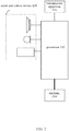
- FIG. 2 is a block diagram of hardware of a mobile terminal for a data transmission method according to an embodiment of the present application.
- a mobile terminal 20 may include one or more (merely one is shown in FIG. 2 ) processors 202 (the processor 202 may include a processing apparatus such as a microcontroller unit (MCU) and a field-programmable gate array (FPGA)), and a memory 204 configured to store data.
- the foregoing mobile terminal may further include a transmission apparatus 206 configured to implement a communication function and an input and output device 208.
- the structure shown in FIG. 2 is merely illustrative and not intended to limit the structure of the foregoing mobile terminal.
- the mobile terminal 20 may further include more or fewer components than the components shown in FIG. 2 , or may have a configuration different from the configuration shown in FIG. 2 .
- the memory 204 may be configured to store software programs and modules of application software, such as program instructions/modules corresponding to the data transmission method in the embodiments of the present application.
- the one or more processors 202 execute the software programs and modules stored in the memory 204 to perform multiple functional applications and data processing, that is, to implement the foregoing method.
- the memory 204 may include a high-speed random access memory, and may further include a nonvolatile memory such as one or more magnetic storage apparatuses, flash memories, or other nonvolatile solid-state memories.
- the memory 204 may further include memories that are remotely disposed with respect to the one or processors 202. These remote memories may be connected to the mobile terminal 20 via a network.
- the examples of the foregoing network include, but are not limited to, the Internet, an intranet, a local area network, a mobile communication network, and a combination thereof.
- the transmission apparatus 206 is configured to receive or send data via a network. Examples of such a network may include a wireless network provided by a communication provider of the mobile terminal 20.
- the transmission apparatus 206 includes a network interface controller (NIC) and may be connected to other network equipment via a base station and thus be capable of communicating with the Internet.
- the transmission apparatus 206 may be a radio frequency (RF) module and is configured to communicate with the Internet in a wireless manner.
- RF radio frequency
- FIG. 3 is a flowchart of a data transmission method according to an embodiment of the present application. As shown in FIG. 3 , the method includes the steps described below.
- a first terminal acquires first information of quality of service (QoS) of a to-be-transmitted data packet on a sidelink.
- QoS quality of service
- step S304 a sidelink bearer is configured.
- step S306 the to-be-transmitted data packet is mapped to the sidelink bearer according to the first information for transmission to a second terminal.
- the to-be-transmitted data packet may be a sidelink data packet.
- the first terminal acquires the first information of the quality of service (QoS) of the to-be-transmitted data packet on the sidelink, configures the sidelink bearer, and maps, according to the first information, the to-be-transmitted data packet to the sidelink bearer for transmission to the second terminal.
- QoS quality of service
- sidelink traffic transmission is performed according to the first information related to QoS.
- a solution of sidelink bearer mapping suitable for the new radio is provided, solving the problem in the related art of lacking a solution of determining a sidelink bearer suitable for the new radio.
- the technical solution regarding the sidelink bearer in the present application may be applied to a logical channel.
- the foregoing steps may be executed by a mobile terminal such as a vehicle.
- the first information includes at least one of: second information including a fifth-generation mobile system quality of service identifier (5QI) and/or a transmission range corresponding to the to-be-transmitted data packet; third information including at least one of the following information corresponding to the to-be-transmitted data packet: a priority, reliability, a transmission delay, a data rate, a packet error rate, or a transmission range; fourth information including sidelink QoS rules; or fifth information including a sidelink QoS profile.
- 5QI fifth-generation mobile system quality of service identifier
- third information including at least one of the following information corresponding to the to-be-transmitted data packet: a priority, reliability, a transmission delay, a data rate, a packet error rate, or a transmission range
- fourth information including sidelink QoS rules
- fifth information including a sidelink QoS profile.
- the step in which the first terminal acquires the first information of the quality of service (QoS) on the sidelink includes that the first terminal acquires the second information or the third information from a V2X application layer.
- V2X may be a data transmission between a vehicle and X and includes vehicle-to-vehicle communication, vehicle-to-pedestrian communication, vehicle-to-infrastructure communication, and the like.
- the step in which the first terminal acquires the first information of the quality of service (QoS) on the sidelink includes one of the following: the first terminal acquires the fourth information and/or the fifth information from a V2X control function entity; the first terminal acquires the fourth information and/or the fifth information from preconfigured information; or the first terminal acquires the fourth information from an access and mobility management function entity at the network side.
- QoS quality of service
- the fourth information includes at least one of: a 5QI, a guaranteed flow bit rate (GFBR), a maximum flow bit rate (MFBR), or an averaging window.
- GFBR guaranteed flow bit rate
- MFBR maximum flow bit rate
- the sidelink QoS rules are the same as or different from the Uu (user equipment) QoS rules of the first terminal.
- the step of configuring the sidelink bearer includes one of the following: the first terminal independently configures the sidelink bearer according to the fourth information and/or the fifth information; or the first terminal sends sidelink bearer configuration information to the second terminal, receives sidelink bearer configuration response information fed back by the second terminal, and configures the sidelink bearer according to the sidelink bearer configuration response information.
- the sidelink bearer configuration information includes at least one of: a bearer identifier, a service data adaptation protocol (SDAP) configuration, a packet data convergence protocol (PDCP) configuration, a radio link control (RLC) configuration, a logical channel configuration, a mirror QoS indication, or a QoS parameter.
- SDAP service data adaptation protocol
- PDCP packet data convergence protocol
- RLC radio link control
- the QoS parameter includes multiple information: the 5QI, the GFBR, the MFBR, and the averaging window.
- the method satisfies at least one of the features described below.
- the SDAP configuration includes at least one of: NULL, a default bearer indication, a list of QoS flows mapped to the bearer, or whether an SDAP subheader is included.
- the PDCP configuration includes at least one of: a packet discarding timer, a length of a PDCP sequence number, header compression, or a reordering timer.
- the RLC configuration includes at least one of: a non-acknowledgement mode or an acknowledgement mode, a polling-related configuration in an acknowledgement mode, a maximum number of retransmissions in an acknowledgement mode, or whether out-of-order delivery is supported.
- the logical channel configuration includes at least one of: a logical channel identifier, a logical channel priority, a prioritized guaranteed bit rate, bucket size duration, subcarrier spacing, an associated sidelink bandwidth part (BWP) index, or an associated carrier indication.
- the QoS parameter includes at least one of: a 5QI, an allocation retention priority, a UE-PC5-aggregate maximum bit rate (AMBR), a PC5 guaranteed flow bit rate (GFBR), a PC5 maximum flow bit rate (MFBR), a PC5 mirror QoS indication, a priority, a packet delay, a packet error rate, reliability, or a resource type.
- a 5QI a 5QI
- ABR UE-PC5-aggregate maximum bit rate
- GFBR PC5 guaranteed flow bit rate
- MFBR maximum flow bit rate
- PC5 mirror QoS indication a priority, a packet delay, a packet error rate, reliability, or a resource type.
- the sidelink bearer configuration response information includes at least one of: a list of sidelink bearers supported by the second terminal or a list of sidelink bearers not supported by the second terminal. The reason why the sidelink bearers are not supported by the second terminal may also be included.
- the step of configuring the sidelink bearer includes that: the first terminal receives sidelink bearer configuration information sent by a base station; and the sidelink bearer is configured according to the sidelink bearer configuration information.
- the step of mapping, according to the first information, the to-be-transmitted data packet to the sidelink bearer for the transmission includes one of the following: in response to the first information being the second information, mapping a to-be-transmitted data packet associated with a first 5QI to a sidelink bearer associated with the first 5QI for the transmission; or in response to the first information being the fourth information, mapping, according to the sidelink rules and the sidelink bearer configuration information, the to-be-transmitted data packet to a corresponding sidelink bearer for the transmission.
- the step of mapping, according to the sidelink rules, the to-be-transmitted data packet to the corresponding sidelink bearer for the transmission includes that: the first terminal maps the to-be-transmitted data packet to a QoS flow according to the sidelink rules; and a sidelink SDAP entity of the first terminal maps the QoS flow to the sidelink bearer for the transmission.
- the method includes that: in the first terminal, the sidelink SDAP entity is the same as or different from a Uu SDAP entity.
- the step in which the sidelink SDAP entity of the first terminal maps the QoS flow to the sidelink bearer for the transmission includes the cases described below.
- the first terminal determines a rule of mapping between the QoS flow and the sidelink bearer.
- the first terminal maps, according to a mapping relationship of the non-empty list, the QoS flow to the sidelink bearer for the transmission.
- the SDAP entity of the first terminal marks a QoS flow identifier (QFI) corresponding to a data packet of the QoS flow.
- QFI QoS flow identifier
- the QFI and the QoS flow are configured for providing a basis for a peer UE to update a first mapping relationship which is a mapping relationship between a QFI and a sidelink bearer stored by the peer UE.
- the method further includes: the first terminal acquiring traffic switch information; and performing traffic switch according to the traffic switch information, where the traffic switch is configured for switching the to-be-transmitted data packet between a Uu interface and a PC5 interface.
- the traffic switch information includes at least one of: application layer information, access layer information, or traffic switch indication information configured by a base station.
- the method satisfies at least one of the features described below.
- the application layer information includes at least one of: a data packet traffic type, a QoS flow traffic type, or QoS demand information.
- the QoS demand information includes at least one of: a priority, a delay, reliability, a transmission rate, a data rate, or a transmission range.
- the access layer information includes at least one of: Uu link quality, Uu reference signal received power, a Uu bearer and QoS parameter, a Uu congestion degree, PC5 link quality, a PC5 connection establishment state, a PC5 channel busy-idle rate, a PC5 discovery signal received power, a PC5 synchronization signal received power, a PC5 resource conflict probability, a PC5 congestion situation, a PC5 bearer, or a QoS parameter.
- the traffic switch indication information configured by the base station includes at least one of: a traffic switch indication, a Uu link quality threshold, a PC5 link quality threshold, a delay threshold, a reliability threshold, a data rate threshold, a traffic type, an application type, a QoS flow identifier (QFI) of a switched PC5 QoS flow, a mapping relationship between a switched PC5 QoS flow and a data radio bearer (DRB), information about a switched Uu QoS flow, or a mapping relationship between a switched Uu QoS flow and a sidelink bearer.
- QFI QoS flow identifier
- information about a Uu QoS flow includes a PDU session identifier and a QFI.
- the step of performing the traffic switch according to the traffic switch information includes one of the steps described below.
- the first terminal maps the fourth data packet to a fourth QoS flow through Uu QoS rules, and an SDAP entity of the first terminal maps the fourth QoS flow to a DRB for transmission.
- the application layer of the first terminal determines that a fifth data packet is transmitted via the PC5 interface
- the application layer of the first terminal configures a fifth 5QI corresponding to the fifth data packet
- the first terminal maps the fifth data packet to a sidelink bearer associated with the fifth 5QI.
- the first terminal switches and maps a QoS flow of a fourth QFI transmitted via the Uu interface to a sidelink bearer associated with a same 5QI or the fourth QFI in the PC5 interface.
- the first terminal acquires a sixth data packet associated with a sixth 5QI at the PC5 interface and maps the sixth data packet to a sixth QoS flow of the sixth 5QI in the Uu interface or to a newly established seventh QoS flow; and an SDAP entity of the first terminal maps the sixth QoS flow or the seventh QoS flow to a DRB.
- the first terminal determines, according to the traffic switch information, that a seventh data packet is transmitted at the PC5 interface, the first terminal maps the seventh data packet to a PC5 QoS flow through PC5 QoS rules, and an SDAP entity of the first terminal maps the PC5 QoS flow to a sidelink bearer for transmission.
- the first terminal maps a data packet to an eighth QoS flow according to QoS rules, in response to determining that the eighth QoS flow is transmitted via the Uu interface, eighth information of a transmission path is indicated to an SDAP entity of the first terminal, and the SDAP entity of the first terminal maps, according to the eighth information, the eighth QoS flow to a DRB for transmission.
- the first terminal maps a data packet to a ninth QoS flow according to QoS rules, in response to determining that the ninth QoS flow is transmitted via the PC5 interface, ninth information of a transmission path is indicated to an SDAP entity of the first terminal, and the SDAP entity of the first terminal maps, according to the ninth information, the ninth QoS flow to a sidelink bearer for transmission.
- the method further includes at least one of the following: the first terminal sends first notification information to a base station, and the base station updates the mapping relationship between a DRB and a QFI according to the first notification information; or the first terminal sends a second notification message to the second terminal, where the second terminal updates a mapping relationship between a sidelink bearer and a QFI or releases a PC5 connection with the first terminal according to the second notification message.
- a traffic switch method is further provided according to another embodiment of the present application.
- the method includes steps described below.
- step 110 a first terminal acquires traffic switch information.
- step 210 traffic switch is performed according to the traffic switch information, where the traffic switch is configured for switching a to-be-transmitted data packet between a Uu interface and a PC5 interface.
- the first terminal acquires the traffic switch information and the switch is performed according to the traffic switch information.
- a manner of traffic switch between the Uu interface and the PC5 interface suitable for the new radio is provided, solving the problem in the related art of lacking a solution of traffic switch between the Uu interface and the PC5 interface suitable for the new radio.
- the traffic switch information includes at least one of: application layer information, access layer information, or traffic switch indication information configured by a base station.
- the method satisfies at least one of the features described below.
- the application layer information includes at least one of: a data packet traffic type, a QoS flow traffic type, or QoS demand information.
- the QoS demand information includes at least one of: a priority, a delay, reliability, a transmission rate, a data rate, or a transmission range.
- the access layer information includes at least one of: Uu link quality, Uu reference signal received power, a Uu bearer and QoS parameter, a Uu congestion degree, PC5 link quality, a PC5 connection establishment state, a PC5 channel busy-idle rate, a PC5 discovery signal received power, a PC5 synchronization signal received power, a PC5 resource conflict probability, a PC5 congestion situation, a PC5 bearer, or a QoS parameter.
- the traffic switch indication information configured by the base station includes at least one of: a traffic switch indication, a Uu link quality threshold, a PC5 link quality threshold, a delay threshold, a reliability threshold, a data rate threshold, a traffic type, an application type, a QoS flow identifier (QFI) of a switched PC5 QoS flow, a mapping relationship between a switched PC5 QoS flow and a DRB, information about a switched Uu QoS flow, or a mapping relationship between a switched Uu QoS flow and a sidelink bearer.
- QFI QoS flow identifier
- Information about a Uu QoS flow includes a PDU session identifier and a QFI.
- the step of performing the traffic switch according to the traffic switch information includes one of the steps described below.
- the first terminal independently decides, according to the traffic switch information, to perform the traffic switch.
- the first terminal acquires traffic switch indication information sent by the base station, and performs the traffic switch according to the traffic switch indication information.
- the step of performing the traffic switch according to the traffic switch information includes one of the steps described below.
- Traffic switch for each data packet is performed according to the traffic switch information.
- Traffic switch for each QoS flow is performed according to the traffic switch information.
- the step of performing the traffic switch according to the traffic switch information includes one of the steps described below.
- the first terminal maps the fourth data packet to a fourth QoS flow through Uu QoS rules, and an SDAP entity of the first terminal maps the fourth QoS flow to a DRB for transmission.
- the application layer of the first terminal determines that a fifth data packet is transmitted via the PC5 interface
- the application layer of the first terminal configures a fifth 5QI corresponding to the fifth data packet
- the first terminal maps the fifth data packet to a sidelink bearer associated with the fifth 5QI.
- the first terminal switches and maps a QoS flow of a fourth QFI transmitted via the Uu interface to a sidelink bearer associated with a same 5QI or the fourth QFI in the PC5 interface.
- the first terminal acquires a sixth data packet associated with a sixth 5QI at the PC5 interface and maps the sixth data packet to a sixth QoS flow of the sixth 5QI in the Uu interface or to a newly established seventh QoS flow; and an SDAP entity of the first terminal maps the sixth QoS flow or the seventh QoS flow to a DRB.
- the first terminal determines, according to the traffic switch information, that a seventh data packet is transmitted at the PC5 interface, the first terminal maps the seventh data packet to a PC5 QoS flow through PC5 QoS rules, and an SDAP entity of the first terminal maps the PC5 QoS flow to a sidelink bearer for transmission.
- the first terminal maps a data packet to an eighth QoS flow according to QoS rules, in response to determining that the eighth QoS flow is transmitted via the Uu interface, eighth information of a transmission path is indicated to an SDAP entity of the first terminal, and the SDAP entity of the first terminal maps, according to the eighth information, the eighth QoS flow to a DRB for transmission.
- the first terminal maps a data packet to a ninth QoS flow according to QoS rules, in response to determining that the ninth QoS flow is transmitted via the PC5 interface, ninth information of a transmission path is indicated to an SDAP entity of the first terminal, and the SDAP entity of the first terminal maps, according to the ninth information, the ninth QoS flow to a sidelink bearer for transmission.
- the to-be-transmitted data packet is mapped to a QoS flow according to QoS rules, and the SDAP entity of the first terminal maps the QoS flow to a data radio bearer (DRB) for transmission.
- DRB data radio bearer
- the step in which the SDAP entity of the first terminal maps the sixth QoS flow, the seventh QoS flow, or the eighth QoS flow to the DRB includes one of the steps described below.
- the SDAP entity of the first terminal maps, according to a mapping relationship between a QoS flow and a DRB in a sidelink bearer configuration, the sixth QoS flow, the seventh QoS flow, or the eighth QoS flow to the DRB for transmission.
- the SDAP entity of the first terminal maps the sixth QoS flow, the seventh QoS flow, or the eighth QoS flow to a default DRB for transmission.
- the first terminal In response to not configuring a mapping relationship between a QoS flow and a DRB, the first terminal initiates a session request to establish a new session and configures the mapping relationship between the QoS flow and the DRB, or the first terminal initiates a session request to modify a current session and configures the mapping relationship between the QoS flow and the DRB.
- the method before the SDAP entity of the first terminal maps the PC5 QoS flow to the sidelink bearer for the transmission, the method further includes that the first terminal acquires a second mapping relationship between the PC5 QoS flow and the sidelink bearer in one of the manners described below.
- the first terminal independently determines the second mapping relationship.
- the second mapping relationship configured by a base station is received.
- the first terminal and a peer terminal determine the second mapping relationship through negotiation.
- Mirror mapping is performed according to a third mapping relationship between a sidelink bearer and a PC5 QoS flow of a peer terminal to acquire the second mapping relationship.
- the method further includes at least one of the following steps:
- the first notification message is used to indicate that the tenth QoS flow transmitted at the Uu interface is switched to the PC5 interface.
- the first terminal after the first terminal sends the first notification information to the base station, the first terminal receives the sidelink bearer configuration configured by the base station for the first terminal according to the QoS parameter of the tenth QoS flow.
- a V2X application layer associates a V2X packet to a corresponding 5QI.
- the V2X application layer carries the 5QI corresponding to the V2X packet when transmitting the V2X packet to an access (AS) layer.
- Each SL logical channel (LCH) is associated with one or more 5QIs (the mapping relationship between an SL LCH and a 5QI is implemented by the UE or configured by the eNB).
- the UE maps, according to the 5QI associated with the V2X packet, the packet to the SL LCH associated with the same 5QI.
- the 5QI may be standardized, pre-configured, or dynamically allocated. Each 5QI includes at least one of: a priority, a delay, a packet error rate, a resource type, or an averaging window.
- the V2X application layer may also carry the required transmission range when transmitting the V2X packet to the AS layer.
- the Prose Per Packet Priority (PPPP) of the V2X data packet (which may derive a packet delay budget (PDB)) and ProSe per packet reliability (PPPR) are carried.
- PDB packet delay budget
- PPPP ProSe Per Packet Priority
- Each SL LCH is associated with one priority, and the UE maps the data packet to the SL LCH having the same priority for transmission. After obtaining the delay according to the priority, the UE AS tells the delay requirement to a physical layer, and the physical layer considers the delay when selecting resources.
- the V2X application layer merely needs to provide one 5QI value instead of a set of parameters, reducing overhead.
- the UE is pre-configured with sidelink QoS rules or obtains sidelink QoS rules from a V2X control function, the sidelink QoS rules being configured for mapping V2X packets to sidelink QoS flows.
- the UE is pre-configured with sidelink QoS profiles or obtains sidelink QoS profiles from the V2X control function, the sidelink QoS profiles being used as reference to establish a sidelink radio bearer (SL RB).
- SL RB sidelink radio bearer
- FIG. 4 is a schematic diagram of UE data mapping according to embodiment 2 of the present application.
- the UE maps V2X packets to QoS flows according to sidelink QoS rules (each QoS flow is associated with one QFI), finds the QoS parameter in the corresponding QoS profile according to the QFI of the QoS flow, and then establishes an SL RB according to the QoS parameter.
- Multiple QoS flows may be transmitted through one SL RB, and the mapping relationship between the QFI and the SL RB may be implemented by the UE.
- An SDAP layer is added to the sidelink and is used for mapping the QoS flow to the SL RB, and each UE has one SDAP entity.
- the UE independently establishes the sidelink bearer according to the arrived data packet and the QoS parameter corresponding to the data packet. This manner may also be used for sidelink unicast communication.
- a source UE sends the sidelink bearer-related configuration information to a target UE.
- Such configuration information includes at least one of: a bearer identifier, an SDAP configuration, a PDCP configuration, an RLC configuration, a logical channel configuration, a mirror QoS indication, or a QoS parameter.
- the SDAP configuration includes at least one of: NULL, a default bearer indication, a list of QoS flows (QFIs) mapped to the bearer, or whether an SDAP subheader is included.
- the PDCP configuration includes at least one of: a packet discarding timer, a length of a PDCP sequence number, header compression, or a reordering timer.
- the RLC configuration includes at least one of: a non-acknowledgement mode or an acknowledgement mode, a polling-related configuration in an acknowledgement mode, a maximum number of retransmissions in an acknowledgement mode, or whether out-of-order delivery exists.
- the logical channel configuration includes at least one of: a logical channel identifier, a logical channel priority, a prioritized guaranteed bit rate, bucket size duration, subcarrier spacing, an associated sidelink BWP index, or an associated carrier indication.
- the SDAP configuration indicates NULL or the list of QoS flows mapped to the bearer is empty, a mapping relationship between the QoS flow and the SL RB is implemented by the sending UE itself. If the list of QoS flows mapped to the bearer is non-empty, the two UEs map the QoS flow to the SL RB according to the mapping relationship. If the list of QoS flows mapped to the bearer is non-empty and an indication of supporting mirror QoS exists, the UE SDAP entity marks a QFI corresponding to a data packet, and the peer UE may update the mapping relationship between the SL RB and the QFI (QoS flow) according to the marked QFI of the data packet and the SL RB configuration of the peer UE.
- the QoS parameter includes at least one of: a 5QI, an allocation retention priority, a UE-PC5-aggregate maximum bit rate (AMBR), a PC5 guaranteed flow bit rate (GFBR), a PC5 maximum flow bit rate (MFBR), a PC5 mirror QoS indication, a priority, a packet delay, a packet error rate, reliability, or a resource type.
- a 5QI a 5QI
- ABR UE-PC5-aggregate maximum bit rate
- GFBR PC5 guaranteed flow bit rate
- MFBR maximum flow bit rate
- PC5 mirror QoS indication a priority, a packet delay, a packet error rate, reliability, or a resource type.
- the target UE After receiving the sidelink bearer configuration information, the target UE evaluates whether these sidelink bearer configurations can be supported and feeds back sidelink bearer configuration response information which includes a list of supported sidelink bearers, a list of unsupported sidelink bearers, reasons for not supporting, etc.
- the reasons for not supporting may be as follows: QoS requirements cannot be guaranteed, sidelink resources are insufficient, the sidelink resource conflict probability is high, etc.
- FIG. 5 is a schematic diagram of a sidelink unicast bearer configuration according to embodiment 2 of the present application.
- the sidelink bearer may be configured by the base station for the UE.
- a UE NAS obtains sidelink QoS rules from the AMF and maps the V2X packet to a QoS flow.
- the gNB obtains QoS profiles from the AMF to configure the sidelink bearer for the UE and configure an optional mapping relationship between the SL RB and the QoS flow (QFI).
- QFI QoS flow
- the UE SDAP entity maps the QoS flow to the SL RB for transmission.
- Sidelink QoS rules and Uu QoS rules may be interchangeable.
- the sidelink bearer configuration by the gNB for the UE includes at least one of: a bearer identifier, an SDAP configuration, a PDCP configuration, an RLC configuration, a logical channel configuration, a mirror QoS indication, or a QoS parameter.
- the SL RB-related configuration of the receiving UE is as follows: 1) the gNB broadcasts the SL RB-related configuration information of the sending UE (through a destination (dest) ID) through a broadcast message; 2) if the gNB knows the peer UE (connected state) of the sending UE, the gNB can configure the SL RB for the peer UE; 3) the sending UE sends the SL RB configuration to the receiving UE.
- Traffic switch from a Uu interface to a PC5 interface is as described below.
- V2X V2V/V2I/V2N/V2P
- V2X V2V/V2I/V2N/V2P
- part of V2V traffic can be considered to be switched to the PC5 interface for transmission when the Uu interface is congested or heavily loaded, QoS cannot be satisfied due to some traffic delay at the Uu interface, or the Uu link quality deteriorates while the PC5 interface has small load, sufficient resources, and low channel busy-idle rate.
- the application layer can recognize that the UE communicating via the Uu interface and discovered through the SL discovery is the same UE, and the UE establishes s PC5 connection with the peer UE.
- the Uu interface is congested or heavily loaded, QoS cannot be satisfied due to some traffic delay at the Uu interface, or the Uu link quality deteriorates, part of V2V traffic is switched to the PC5 interface for transmission.
- the UE For traffic switch from the PC5 interface to the Uu interface, when a UE is detected to have been within the coverage, the UE establishes an RRC connection with the base station; if the PC5 interface is congested, has high channel busy-idle rate, or has a high resource conflict probability or the PC5 link quality deteriorates, the UE can switch the traffic at the PC5 interface to the Uu interface for transmission.
- FIG. 6 is a schematic diagram of V2X data packet-based traffic switch according to embodiment 3 of the present application.
- the application layer switches, according to a traffic type, a delay, reliability, and the like, a V2V packet originally transmitted via the Uu interface to the PC5 interface for transmission, associates the packet with a 5QI, and provides the packet to the AS layer.
- Each SL LCH is associated with one or more 5QIs.
- the AS layer maps the packet to the SL LCH associated with the same 5QI.
- the AS layer needs to provide a load situation at the Uu interface, the Uu link quality, a state (connection/availability) of the PC5 interface, a PC5 resource utilization rate, a PC5 channel busy-idle rate, the PC5 link quality and other information.
- the UE application layer switches the packet originally transmitted via the PC5 interface to the Uu interface and maps the packet to a QoS flow through Uu QoS rules, and then the UE SDAP entity maps the QoS flow to a corresponding DRB for transmission.
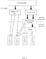
- FIG. 7 is a flowchart of traffic switch from a Uu interface to a PC5 interface according to embodiment 3 of the present application.
- a QoS flow originally transmitted via the Uu interface (each QoS flow has a corresponding QFI and 5QI) is switched/mapped to an SL LCH (the SL LCH is associated with the 5QI).
- the application layer needs to provide the traffic types corresponding to QoS flows, so as to determine which QoS flows to switch.
- the AS layer provides the connection states, congestion situations, resource situations, link qualities, and the like of the Uu interface and the PC5 interface.
- the UE combines the application layer and AS layer information to determine which QoS flow to switch to the PC5 interface.
- FIG. 8 is a flowchart of traffic switch from a PC5 interface to a Uu interface according to embodiment 3 of the present application.
- V2X packets associated with a particular 5QI and originally transmitted via the PC5 interface are mapped to a QoS flow having the same 5QI at the Uu interface or as a new QoS flow and then mapped to a DRB for transmission according to a mapping relationship between a QoS flow and a DRB at the Uu interface.
- the QoS flow is mapped to a default DRB, or a PDU session modification/request process is initiated to establish a new DRB or update the mapping relationship between the QoS flow and the DRB to transmit the QoS flow.
- Embodiment 4 Traffic switch based on the QoS framework of embodiment 2 is described below.
- FIG. 9 is a schematic diagram of V2X data packet-based traffic switch according to embodiment 4 of the present application.
- the application layer determines V2V traffic, and selects, based on traffic QoS requirements, some V2V traffic to be switched to the PC5 interface for transmission.
- the application layer maps a V2X packet to a QoS flow (PC5) according to PC5 QoS rules and submits the V2X packet to the AS layer (PC5).
- the UE SDAP entity maps the PC5 QoS flow to an SL RB for transmission, where a mapping relationship between the PC5 QoS flow and the SL RB may be implemented by the UE or configured by the gNB.
- the AS layer needs to provide states (RRC/PC5 connection states), congestion situations, resource usage situations, link qualities and other information of the Uu interface and the PC5 interface.
- the application layer switches, based on traffic QoS requirements, some traffic at the PC5 interface to the Uu interface for transmission and then maps the traffic to QoS flows (Uu) through Uu QoS rules. Conventional data routing processing is performed at the Uu interface.
- FIG. 10 is a schematic diagram of QoS flow-based traffic switch according to embodiment 4 of the present application.
- the UE application layer provides the traffic type and QoS requirement corresponding to a QoS flow
- the AS layer provides the state, congestion situation, resource usage situation, and link quality of the Uu interface and/or the PC5 interface, the SL RB situation at the PC5 interface and the DRB situation at the Uu interface.
- the UE combines the application layer information and the AS layer information to decide whether to switch some traffic from the Uu interface to the PC5 interface for transmission and which QoS flow traffic to switch.
- the UE upper layer indicates to the SDAP layer whether a QoS flow is transmitted via the Uu interface or the PC5 interface.
- the UE SDAP entity maps the QoS flow transmitted via the PC5 interface to the sidelink bearer for transmission, and the mapping relationship between the QoS flow and the SL RB may be implemented by the UE or configured by the gNB. If no suitable SL RBs are provided for some particular QoS flows switched from the Uu interface to the PC5 interface, suitable SL RBs need to be established first.
- the UE For traffic switch from the PC5 interface to the Uu interface, the UE combines the application layer information and the AS layer information to decide whether to switch some traffic from the PC5 interface to the Uu interface for transmission and which QoS flow traffic to switch.
- the UE upper layer indicates to the SDAP layer whether the QoS flow is transmitted via the Uu interface or the PC5 interface.
- the UE SDAP entity maps the QoS flow transmitted via the Uu interface to the DRB for transmission according to the configured mapping relationship between the QoS flow and the DRB and marks the QFI for the data packet.
- the QoS flow is mapped to the default DRB, or a PDU session modification/request process is initiated to establish a new DRB or update the mapping relationship between the QoS flow and the DRB to transmit the QoS flow.
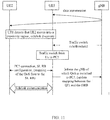
- This embodiment uses the example of switching V2V traffic from the Uu interface to the PC5 interface for sidelink unicast communication to illustrate the traffic switch signaling flow.
- UE1 and UE2 originally perform V2X communication via the Uu interface. If UE1 detects that UE2 moves into a proximity service range and discovers the peer UE2 through sidelink discovery, the application layer can recognize that the UE communicating via the Uu interface and discovered through the SL discovery is the same UE. After UE 1 discovers UE2 through the sidelink discovery, UE1 independently decides or the base station controls to perform traffic switch. In some embodiments:
- This embodiment uses the example of switching V2V traffic from the PC5 interface for sidelink unicast communication to the Uu interface for transmission to illustrate the traffic switch signaling flow.
- UE1 discovers UE2 through the sidelink discovery
- UE1 and UE2 establish a PC5 connection, negotiate a sidelink bearer, and then perform sidelink communication.
- UE1 detects network coverage and establishes an RRC connection with the gNB.
- UE1 can independently decide whether and when to switch V2V traffic at the PC5 interface to the Uu interface for transmission.
- UE1 reports to the gNB state information of the PC5 interface, such as the PC5 link quality, the PC5 congestion situation, the PC5 channel busy-idle rate, the PC5 resource conflict situation, the PC5 bearer and corresponding QoS parameter information, and the mapping relationship between the PC5 bearer and the PC5 QoS flow.
- the traffic switch indication information delivered by the base station includes at least one of: a traffic switch indication, a Uu link quality threshold, a PC5 link quality threshold, a delay threshold, a reliability threshold, information about a switched PC5 QoS flow (QFI), or a mapping relationship between a switched PC5 QoS flow and the DRB.
- FIG. 13 is a flowchart of traffic switch from a PC5 interface to a Uu interface according to embodiment 5 of the present application.
- the method in the foregoing embodiment may be implemented by software plus a necessary general-purpose hardware platform or may of course be implemented by hardware. However, in many cases, the former is a preferred implementation.
- the solutions of the present application substantially, or the part contributing to the existing art, may be embodied in the form of a software product.
- the computer software product is stored on a storage medium (such as a ROM/RAM, a magnetic disk, or an optical disk) and includes one or more instructions to enable a terminal device (which may be a mobile phone, a computer, a server, or a network device) to perform the method according to embodiments of the present application.
- This embodiment further provides a data transmission apparatus and a traffic switch apparatus.
- the apparatuses are configured to implement the foregoing embodiments and preferred embodiments. What has been described will not be repeated.
- the term "module” may be software, hardware, or a combination thereof capable of implementing predetermined functions.
- the apparatuses in this embodiment described below are preferably implemented by software, but an implementation by hardware or by a combination of software and hardware is also possible and conceivable.
- a data transmission apparatus includes a first acquisition module, a first configuration module, and a first mapping module.
- the first acquisition module is configured to acquire first information of quality of service (QoS) of a to-be-transmitted data packet on a sidelink.
- QoS quality of service
- the first configuration module is configured to configure a sidelink bearer.
- the first mapping module is configured to map, according to the first information, the to-be-transmitted data packet to the sidelink bearer for transmission to a second terminal.
- sidelink traffic transmission is performed according to the first information related to QoS.
- a solution of sidelink bearer mapping suitable for the new radio is provided, solving the problem in the related art of lacking a solution of determining a sidelink bearer suitable for the new radio.
- the technical solution regarding the sidelink bearer in the present application may be applied to a logical channel.
- the foregoing steps may, but may not necessarily, be executed by a mobile terminal such as a vehicle.
- the first information includes at least one of: second information including a fifth-generation mobile system quality of service identifier (5QI) and/or a transmission range corresponding to the to-be-transmitted data packet; third information including at least one of the following information corresponding to the to-be-transmitted data packet: a priority, reliability, a transmission delay, a data rate, a packet error rate, or a transmission range; fourth information including sidelink QoS rules; or fifth information including a sidelink QoS profile.
- 5QI fifth-generation mobile system quality of service identifier
- third information including at least one of the following information corresponding to the to-be-transmitted data packet: a priority, reliability, a transmission delay, a data rate, a packet error rate, or a transmission range
- fourth information including sidelink QoS rules
- fifth information including a sidelink QoS profile.
- the step in which the first terminal acquires the first information of the quality of service (QoS) on the sidelink includes that the first terminal acquires the second information or the third information from a V2X application layer.
- QoS quality of service
- the step in which the first terminal acquires the first information of the quality of service (QoS) on the sidelink includes one of the following: the first terminal acquires the fourth information and/or the fifth information from a V2X control function entity; the first terminal acquires the fourth information and/or the fifth information from preconfigured information; or the first terminal acquires the fourth information from an access and mobility management function entity at the network side.
- QoS quality of service
- the fourth information includes at least one of: a 5QI, a guaranteed flow bit rate (GFBR), a maximum flow bit rate (MFBR), or an averaging window.
- GFBR guaranteed flow bit rate
- MFBR maximum flow bit rate
- the sidelink QoS rules are the same as or different from the Uu QoS rules of the first terminal.
- the step of configuring the sidelink bearer includes one of the following: the first terminal independently configures the sidelink bearer according to the fourth information and/or the fifth information; or the first terminal sends sidelink bearer configuration information to the second terminal, receives sidelink bearer configuration response information fed back by the second terminal, and configures the sidelink bearer according to the sidelink bearer configuration response information.
- the sidelink bearer configuration information includes at least one of: a bearer identifier, an SDAP configuration, a PDCP configuration, an RLC configuration, a logical channel configuration, a mirror QoS indication, or a QoS parameter.
- the QoS parameter includes multiple information: the 5QI, the GFBR, the MFBR, and the averaging window.
- the method satisfies at least one of the features described below.
- the SDAP configuration includes at least one of: NULL, a default bearer indication, a list of QoS flows mapped to the bearer, or whether an SDAP subheader is included.
- the PDCP configuration includes at least one of: a packet discarding timer, a length of a PDCP sequence number, header compression, or a reordering timer.
- the RLC configuration includes at least one of: a non-acknowledgement mode or an acknowledgement mode, a polling-related configuration in an acknowledgement mode, a maximum number of retransmissions in an acknowledgement mode, or whether out-of-order delivery is supported.
- the logical channel configuration includes at least one of: a logical channel identifier, a logical channel priority, a prioritized guaranteed bit rate, bucket size duration, subcarrier spacing, an associated sidelink bandwidth part (BWP) index, or an associated carrier indication.
- the QoS parameter includes at least one of: a 5QI, an allocation retention priority, a UE-PC5-aggregate maximum bit rate (AMBR), a PC5 guaranteed flow bit rate (GFBR), a PC5 maximum flow bit rate (MFBR), a PC5 mirror QoS indication, a priority, a packet delay, a packet error rate, reliability, or a resource type.
- a 5QI a 5QI
- ABR UE-PC5-aggregate maximum bit rate
- GFBR PC5 guaranteed flow bit rate
- MFBR maximum flow bit rate
- PC5 mirror QoS indication a priority, a packet delay, a packet error rate, reliability, or a resource type.
- the sidelink bearer configuration response information includes at least one of: a list of sidelink bearers supported by the second terminal or a list of sidelink bearers not supported by the second terminal. The reason why the sidelink bearers are not supported by the second terminal may also be included.
- the step of configuring the sidelink bearer includes that: the first terminal receives sidelink bearer configuration information sent by a base station; and the sidelink bearer is configured according to the sidelink bearer configuration information.
- the step of mapping, according to the first information, the to-be-transmitted data packet to the sidelink bearer for the transmission includes one of the following: in response to the first information being the second information, mapping a to-be-transmitted data packet associated with a first 5QI to a sidelink bearer associated with the first 5QI for the transmission; or in response to the first information being the fourth information, mapping, according to the sidelink rules and the sidelink bearer configuration information, the to-be-transmitted data packet to a corresponding sidelink bearer for the transmission.
- the step of mapping, according to the sidelink rules, the to-be-transmitted data packet to the corresponding sidelink bearer for the transmission includes that: the first terminal maps the to-be-transmitted data packet to a QoS flow according to the sidelink rules; and a sidelink SDAP entity of the first terminal maps the QoS flow to the sidelink bearer for the transmission.
- the method includes that: in the first terminal, the sidelink SDAP entity is the same as or different from a Uu SDAP entity.
- the step in which the sidelink SDAP entity of the first terminal maps the QoS flow to the sidelink bearer for the transmission includes the cases described below.
- the first terminal determines a rule of mapping between the QoS flow and the sidelink bearer.
- the first terminal maps, according to a mapping relationship of the non-empty list, the QoS flow to the sidelink bearer for the transmission.
- the SDAP entity of the first terminal marks a QoS flow identifier (QFI) corresponding to a data packet of the QoS flow.
- QFI QoS flow identifier
- the QFI and the QoS flow are configured for providing a basis for a peer UE to update a first mapping relationship which is a mapping relationship between a QFI and a sidelink bearer stored by the peer UE.
- the method further includes: the first terminal acquiring traffic switch information; and performing traffic switch according to the traffic switch information, where the traffic switch is configured for switching the to-be-transmitted data packet between a Uu interface and a PC5 interface.
- the traffic switch information includes at least one of: application layer information, access layer information, or traffic switch indication information configured by a base station.
- the method satisfies at least one of the features described below.
- the application layer information includes at least one of: a data packet traffic type, a QoS flow traffic type, or QoS demand information.
- the QoS demand information includes at least one of: a priority, a delay, reliability, a transmission rate, a data rate, or a transmission range.
- the access layer information includes at least one of: Uu link quality, Uu reference signal received power, a Uu bearer and QoS parameter, a Uu congestion degree, PC5 link quality, a PC5 connection establishment state, a PC5 channel busy-idle rate, a PC5 discovery signal received power, a PC5 synchronization signal received power, a PC5 resource conflict probability, a PC5 congestion situation, a PC5 bearer, or a QoS parameter.
- the traffic switch indication information configured by the base station includes at least one of: a traffic switch indication, a Uu link quality threshold, a PC5 link quality threshold, a delay threshold, a reliability threshold, a data rate threshold, a traffic type, an application type, a QoS flow identifier (QFI) of a switched PC5 QoS flow, a mapping relationship between a switched PC5 QoS flow and a DRB, information about a switched Uu QoS flow, or a mapping relationship between a switched Uu QoS flow and a sidelink bearer.
- QFI QoS flow identifier
- information about a Uu QoS flow includes a PDU session identifier and a QFI.
- the step of performing the traffic switch according to the traffic switch information includes one of the steps described below.
- the first terminal maps the fourth data packet to a fourth QoS flow through Uu QoS rules, and an SDAP entity of the first terminal maps the fourth QoS flow to a DRB for transmission.
- the application layer of the first terminal determines that a fifth data packet is transmitted via the PC5 interface
- the application layer of the first terminal configures a fifth 5QI corresponding to the fifth data packet
- the first terminal maps the fifth data packet to a sidelink bearer associated with the fifth 5QI.
- the first terminal switches and maps a QoS flow of a fourth QFI transmitted via the Uu interface to a sidelink bearer associated with a same 5QI or the fourth QFI in the PC5 interface.
- the first terminal acquires a sixth data packet associated with a sixth 5QI at the PC5 interface and maps the sixth data packet to a sixth QoS flow of the sixth 5QI in the Uu interface or to a newly established seventh QoS flow; and an SDAP entity of the first terminal maps the sixth QoS flow or the seventh QoS flow to a DRB.
- the first terminal determines, according to the traffic switch information, that a seventh data packet is transmitted at the PC5 interface, the first terminal maps the seventh data packet to a PC5 QoS flow through PC5 QoS rules, and an SDAP entity of the first terminal maps the PC5 QoS flow to a sidelink bearer for transmission.
- the first terminal maps a data packet to an eighth QoS flow according to QoS rules, in response to determining that the eighth QoS flow is transmitted via the Uu interface, eighth information of a transmission path is indicated to an SDAP entity of the first terminal, and the SDAP entity of the first terminal maps, according to the eighth information, the eighth QoS flow to a DRB for transmission.
- the first terminal maps a data packet to a ninth QoS flow according to QoS rules, in response to determining that the ninth QoS flow is transmitted via the PC5 interface, ninth information of a transmission path is indicated to an SDAP entity of the first terminal, and the SDAP entity of the first terminal maps, according to the ninth information, the ninth QoS flow to a sidelink bearer for transmission.
- the method further includes at least one of the following: the first terminal sends first notification information to a base station, and the base station updates the mapping relationship between a DRB and a QFI according to the first notification information; or the first terminal sends a second notification message to the second terminal, where the second terminal updates a mapping relationship between a sidelink bearer and a QFI or releases a PC5 connection with the first terminal according to the second notification message.
- a traffic switch apparatus is further provided according to another embodiment of the present application.
- the apparatus includes a second acquisition module and a second switch module.
- the second acquisition module is configured to enable a first terminal to acquire traffic switch information.
- the second switch module is configured to perform traffic switch according to the traffic switch information, where the traffic switch is configured for switching a to-be-transmitted data packet between a Uu interface and a PC5 interface.
- the first terminal acquires the traffic switch information and the switch is performed according to the traffic switch information.
- a manner of traffic switch between the Uu interface and the PC5 interface suitable for the new radio is provided, solving the problem in the related art of lacking a solution of traffic switch between the Uu interface and the PC5 interface suitable for the new radio.
- the traffic switch information includes at least one of: application layer information, access layer information, or traffic switch indication information configured by a base station.
- the method satisfies at least one of the features described below.
- the application layer information includes at least one of: a data packet traffic type, a QoS flow traffic type, or QoS demand information.
- the QoS demand information includes at least one of: a priority, a delay, reliability, a transmission rate, a data rate, or a transmission range.
- the access layer information includes at least one of: Uu link quality, Uu reference signal received power, a Uu bearer and QoS parameter, a Uu congestion degree, PC5 link quality, a PC5 connection establishment state, a PC5 channel busy-idle rate, a PC5 discovery signal received power, a PC5 synchronization signal received power, a PC5 resource conflict probability, a PC5 congestion situation, a PC5 bearer, or a QoS parameter.
- the traffic switch indication information configured by the base station includes at least one of: a traffic switch indication, a Uu link quality threshold, a PC5 link quality threshold, a delay threshold, a reliability threshold, a data rate threshold, a traffic type, an application type, a QoS flow identifier (QFI) of a switched PC5 QoS flow, a mapping relationship between a switched PC5 QoS flow and a DRB, information about a switched Uu QoS flow, or a mapping relationship between a switched Uu QoS flow and a sidelink bearer.
- QFI QoS flow identifier
- Information about a Uu QoS flow includes a PDU session identifier and a QFI.
- the step of performing the traffic switch according to the traffic switch information includes one of the steps described below.
- the first terminal independently decides, according to the traffic switch information, to perform the traffic switch.
- the first terminal acquires traffic switch indication information sent by the base station, and performs the traffic switch according to the traffic switch indication information.
- the step of performing the traffic switch according to the traffic switch information includes one of the steps described below.
- Traffic switch for each data packet is performed according to the traffic switch information.
- Traffic switch for each QoS flow is performed according to the traffic switch information.
- the step of performing the traffic switch according to the traffic switch information includes one of the steps described below.
- the first terminal maps the fourth data packet to a fourth QoS flow through Uu QoS rules, and an SDAP entity of the first terminal maps the fourth QoS flow to a DRB for transmission.
- the application layer of the first terminal determines that a fifth data packet is transmitted via the PC5 interface
- the application layer of the first terminal configures a fifth 5QI corresponding to the fifth data packet
- the first terminal maps the fifth data packet to a sidelink bearer associated with the fifth 5QI.
- the first terminal switches and maps a QoS flow of a fourth QFI transmitted via the Uu interface to a sidelink bearer associated with a same 5QI or the fourth QFI in the PC5 interface.
- the first terminal acquires a sixth data packet associated with a sixth 5QI at the PC5 interface and maps the sixth data packet to a sixth QoS flow of the sixth 5QI in the Uu interface or to a newly established seventh QoS flow; and an SDAP entity of the first terminal maps the sixth QoS flow or the seventh QoS flow to a DRB.
- the first terminal determines, according to the traffic switch information, that a seventh data packet is transmitted at the PC5 interface, the first terminal maps the seventh data packet to a PC5 QoS flow through PC5 QoS rules, and an SDAP entity of the first terminal maps the PC5 QoS flow to a sidelink bearer for transmission.
- the first terminal maps a data packet to an eighth QoS flow according to QoS rules, in response to determining that the eighth QoS flow is transmitted via the Uu interface, eighth information of a transmission path is indicated to an SDAP entity of the first terminal, and the SDAP entity of the first terminal maps, according to the eighth information, the eighth QoS flow to a DRB for transmission.
- the first terminal maps a data packet to a ninth QoS flow according to QoS rules, in response to determining that the ninth QoS flow is transmitted via the PC5 interface, ninth information of a transmission path is indicated to an SDAP entity of the first terminal, and the SDAP entity of the first terminal maps, according to the ninth information, the ninth QoS flow to a sidelink bearer for transmission.
- the to-be-transmitted data packet is mapped to a QoS flow according to QoS rules, and the SDAP entity of the first terminal maps the QoS flow to a data radio bearer (DRB) for transmission.
- DRB data radio bearer
- the step in which the SDAP entity of the first terminal maps the sixth QoS flow, the seventh QoS flow, or the eighth QoS flow to the DRB includes one of the steps described below.
- the SDAP entity of the first terminal maps, according to a mapping relationship between a QoS flow and a DRB in a sidelink bearer configuration, the sixth QoS flow, the seventh QoS flow, or the eighth QoS flow to the DRB for transmission.
- the SDAP entity of the first terminal maps the sixth QoS flow, the seventh QoS flow, or the eighth QoS flow to a default DRB for transmission.
- the first terminal In response to not configuring a mapping relationship between a QoS flow and a DRB, the first terminal initiates a session request to establish a new session and configures the mapping relationship between the QoS flow and the DRB, or the first terminal initiates a session request to modify a current session and configures the mapping relationship between the QoS flow and the DRB.
- the method before the SDAP entity of the first terminal maps the PC5 QoS flow to the sidelink bearer for the transmission, the method further includes that the first terminal acquires a second mapping relationship between the PC5 QoS flow and the sidelink bearer in one of the manners described below.
- the first terminal independently determines the second mapping relationship.
- the second mapping relationship configured by a base station is received.
- the first terminal and a peer terminal determine the second mapping relationship through negotiation.
- Mirror mapping is performed according to a third mapping relationship between a sidelink bearer and a PC5 QoS flow of a peer terminal to acquire the second mapping relationship.
- the method further includes at least one of the following steps:
- the first notification message is used to indicate that the tenth QoS flow transmitted at the Uu interface is switched to the PC5 interface.
- the first terminal after the first terminal sends the first notification information to the base station, the first terminal receives the sidelink bearer configuration configured by the base station for the first terminal according to the QoS parameter of the tenth QoS flow.
- each module described above may be implemented by software or hardware. Implementation by hardware may, but may not necessarily, be performed in the following manners: the various modules described above are located in the same processor, or each module described above is located in their respective processors in any combination form.
- a storage medium is further provided in this embodiment of the present application.
- the storage medium may be configured to store program codes for executing steps described below.
- the storage medium is further configured to store program codes for executing the steps described below.
- the storage medium may include, but is not limited to, a USB flash disk, a read-only memory (ROM), a random access memory (RAM), a mobile hard disk, a magnetic disk, an optical disk or another medium capable of storing program codes.
- An electronic apparatus is further provided in the embodiments of the present application and includes a memory and a processor.
- the memory stores a computer program
- the processor is configured to execute the computer program to perform the steps in any one of the foregoing method embodiments.
- the electronic apparatus may further include a transmission apparatus and an input and output device.
- the transmission apparatus is connected to the processor.
- the input and output device is connected to the processor.
- the foregoing processor may be configured to execute the steps below through a computer program.
- various modules or steps described above in the present application may be implemented by a general-purpose computing apparatus, the various modules or steps may be concentrated on a single computing apparatus or distributed on a network composed of multiple computing apparatuses.
- the various modules or steps may be implemented by program codes executable by the computing apparatus, so that the modules or steps may be stored in a storage apparatus for execution by the computing apparatus, and in some particular circumstances, the illustrated or described steps may be performed in sequences different from those described herein, or the module or steps may be made into various integrated circuit modules separately, or multiple modules or steps therein may be made into a single integrated circuit module for implementation. In this manner, the present application is not limited to any particular combination of hardware and software.
Landscapes
- Engineering & Computer Science (AREA)
- Computer Networks & Wireless Communication (AREA)
- Signal Processing (AREA)
- Quality & Reliability (AREA)
- Databases & Information Systems (AREA)
- Mobile Radio Communication Systems (AREA)
Applications Claiming Priority (2)
| Application Number | Priority Date | Filing Date | Title |
|---|---|---|---|
| CN201810912164.XA CN110831075A (zh) | 2018-08-10 | 2018-08-10 | 数据传输方法及装置,业务切换方法及装置 |
| PCT/CN2019/100110 WO2020030165A1 (fr) | 2018-08-10 | 2019-08-10 | Procédé et appareil de transmission de données, et procédé et appareil de commutation de service |
Publications (2)
| Publication Number | Publication Date |
|---|---|
| EP3836618A1 true EP3836618A1 (fr) | 2021-06-16 |
| EP3836618A4 EP3836618A4 (fr) | 2022-04-27 |
Family
ID=69414046
Family Applications (1)
| Application Number | Title | Priority Date | Filing Date |
|---|---|---|---|
| EP19846735.9A Pending EP3836618A4 (fr) | 2018-08-10 | 2019-08-10 | Procédé et appareil de transmission de données, et procédé et appareil de commutation de service |
Country Status (4)
| Country | Link |
|---|---|
| US (1) | US20210329487A1 (fr) |
| EP (1) | EP3836618A4 (fr) |
| CN (1) | CN110831075A (fr) |
| WO (1) | WO2020030165A1 (fr) |
Cited By (1)
| Publication number | Priority date | Publication date | Assignee | Title |
|---|---|---|---|---|
| EP4135400A4 (fr) * | 2020-04-30 | 2023-10-11 | Huawei Technologies Co., Ltd. | Procédé et appareil de communication |
Families Citing this family (32)
| Publication number | Priority date | Publication date | Assignee | Title |
|---|---|---|---|---|
| JP2022502921A (ja) * | 2018-09-25 | 2022-01-11 | アイディーエーシー ホールディングス インコーポレイテッド | ユニキャスト及び/又はマルチキャストリンク確立及び維持のためのl2手順 |
| CN113016229A (zh) * | 2018-11-13 | 2021-06-22 | 瑞典爱立信有限公司 | 无线通信系统中副链路服务质量流管理以及相关方法和装置 |
| US20220014973A1 (en) * | 2018-11-16 | 2022-01-13 | Idac Holdings, Inc. | Quality of service adaptation for pc5 reference point communication |
| US11224007B2 (en) * | 2018-11-19 | 2022-01-11 | Huawei Technologies Co., Ltd. | System and method for supporting sidelink radio bearers |
| CN113475158A (zh) * | 2019-02-13 | 2021-10-01 | 康维达无线有限责任公司 | 用于5g中面向连接的车辆对x(vtx)通信的装置、系统、方法和计算机可读介质 |
| ES2897684T3 (es) * | 2019-03-14 | 2022-03-02 | Asustek Comp Inc | Procedimientos y aparatos para el establecimiento de canales lógicos de enlace lateral en un sistema de comunicación inalámbrica |
| US20220191733A1 (en) * | 2019-03-27 | 2022-06-16 | Apple Inc. | Assistance information indication for rat and interface selection for new radio vehicle-to-everything (v2x) |
| CN111866796B (zh) * | 2019-04-30 | 2022-07-22 | 华为技术有限公司 | 用于获取无线承载配置的方法和装置 |
| US20220225156A1 (en) * | 2019-05-01 | 2022-07-14 | Lg Electronics Inc. | Sdap configuration for destination in sidelink communication |
| CN113163454B (zh) | 2020-01-07 | 2022-05-03 | 华硕电脑股份有限公司 | 无线通信系统中请求侧链路传送资源的方法和设备 |
| CN116709424A (zh) * | 2020-04-03 | 2023-09-05 | 华为技术有限公司 | 一种临近服务的数据传输方法、设备及系统 |
| US11838894B2 (en) * | 2020-04-08 | 2023-12-05 | Qualcomm Incorporated | Quality of service or priority configuration for relay user equipment |
| CN113543241A (zh) * | 2020-04-17 | 2021-10-22 | 华为技术有限公司 | 通信接口切换的方法和通信装置 |
| CN117279037A (zh) * | 2020-04-28 | 2023-12-22 | 华为技术有限公司 | 通信方法和装置 |
| CN113573327B (zh) * | 2020-04-28 | 2023-11-10 | 维沃移动通信有限公司 | 远端ue的传输方法、配置方法、装置及电子设备 |
| CN117693022A (zh) * | 2020-04-29 | 2024-03-12 | 华为技术有限公司 | 一种数据通信方法 |
| CN113660680B (zh) * | 2020-05-12 | 2023-11-07 | 维沃移动通信有限公司 | 副链路中继架构中的配置方法和设备 |
| CN113747509A (zh) * | 2020-05-27 | 2021-12-03 | 华为技术有限公司 | 一种通信方法及相关设备 |
| CN113766575A (zh) * | 2020-06-04 | 2021-12-07 | 华为技术有限公司 | 通信方法及通信设备 |
| CN113784415A (zh) * | 2020-06-09 | 2021-12-10 | 华为技术有限公司 | 一种建立中继承载的方法及通信装置 |
| CN113810949A (zh) * | 2020-06-12 | 2021-12-17 | 华为技术有限公司 | 数据传输方法和装置 |
| US11849346B2 (en) * | 2020-08-19 | 2023-12-19 | Arris Enterprises Llc | Unilateral quality-of-service mirroring |
| CN111970735B (zh) * | 2020-08-27 | 2023-12-26 | 北京中科晶上科技股份有限公司 | 数据传输方法及装置,VoWiFi通信的方法 |
| CN114339714B (zh) * | 2020-09-29 | 2023-07-11 | 维沃移动通信有限公司 | 传输配置的方法、装置和设备 |
| KR20220066840A (ko) * | 2020-11-16 | 2022-05-24 | 아서스테크 컴퓨터 인코포레이션 | 무선 통신 시스템에서 uu 무선 베어러 대 pc5 무선 링크 제어(rlc) 베어러 매핑을 위한 방법 및 장치 |
| US11671815B2 (en) * | 2020-12-22 | 2023-06-06 | Qualcomm Incorporated | Frequency range 2 (FR2) sidelink discovery |
| CN114793357A (zh) * | 2021-01-26 | 2022-07-26 | 展讯通信(上海)有限公司 | 同步传输方法及装置、存储介质、发送端设备、接收端设备 |
| CN114666265B (zh) * | 2022-03-28 | 2024-04-02 | 阿里巴巴(中国)有限公司 | 数据传输方法、装置、计算设备及介质 |
| CN117998652A (zh) * | 2022-11-03 | 2024-05-07 | 华为技术有限公司 | 一种通信方法和相关设备 |
| CN116017560B (zh) * | 2022-12-27 | 2024-04-19 | 深圳市领创星通科技有限公司 | 数据转发方法和系统 |
| CN116761210B (zh) * | 2023-08-11 | 2023-12-15 | 深圳国人无线通信有限公司 | 5qi业务流到drb的映射方法和系统 |
| CN116828555A (zh) * | 2023-08-30 | 2023-09-29 | 华砺智行(武汉)科技有限公司 | Pc5和uu自主切换的通信系统和方法 |
Family Cites Families (15)
| Publication number | Priority date | Publication date | Assignee | Title |
|---|---|---|---|---|
| CN106604336B (zh) * | 2011-09-29 | 2020-03-20 | 华为技术有限公司 | 通信模式切换的方法和装置 |
| JP6239280B2 (ja) * | 2013-06-27 | 2017-11-29 | 京セラ株式会社 | ユーザ端末、プロセッサ及び移動通信システム |
| WO2015163625A1 (fr) * | 2014-04-24 | 2015-10-29 | Lg Electronics Inc. | Procédé de création d'entités de couche 2 pour un système de communication d2d et dispositif associé |
| US20170188404A1 (en) * | 2014-05-23 | 2017-06-29 | Telefonaktiebolaget Lm Ericsson (Publ) | User equipment, a network node, a first and a second core network node, and methods therein for enabling radio admission control (rac) of device-to-device (d2d) services |
| CN106162930B (zh) * | 2015-04-07 | 2021-08-06 | 中兴通讯股份有限公司 | 在设备直通系统中承载的管理方法和装置 |
| CN106341839B (zh) * | 2015-07-07 | 2019-08-30 | 电信科学技术研究院 | 一种信息上报、接收,承载建立的方法及装置 |
| CN106470384A (zh) * | 2015-08-18 | 2017-03-01 | 北京信威通信技术股份有限公司 | 一种d2d通信中的承载配置方法 |
| EP3148285B1 (fr) * | 2015-09-25 | 2019-04-17 | Panasonic Intellectual Property Corporation of America | Mappage de liens radio amélioré pour relais terminal cellulaire a réseau de 3gpp proximity services au moyen d'une signalisation de la priorité du traffic |
| CN106658424B (zh) * | 2015-11-02 | 2019-01-25 | 中兴通讯股份有限公司 | 车联网v2x业务的发送方法及装置 |
| CN107018162B (zh) * | 2016-01-28 | 2021-03-16 | 电信科学技术研究院 | 一种进行数据传输的方法和终端 |
| WO2017146710A1 (fr) * | 2016-02-25 | 2017-08-31 | Nokia Solutions And Networks Oy | Techniques permettant de fournir des informations concernant la priorité de services de proximité (prose) à une station de base dans un réseau sans fil |
| CN113316197A (zh) * | 2016-04-05 | 2021-08-27 | 华为技术有限公司 | QoS生成方法、设备以及系统 |
| CN107580340B (zh) * | 2016-07-05 | 2020-01-17 | 普天信息技术有限公司 | 一种v2x网络中的资源调度方法 |
| US10397836B2 (en) * | 2016-10-27 | 2019-08-27 | Ofinno, Llc | Handover for UE with V2X service |
| US11665730B2 (en) * | 2017-01-09 | 2023-05-30 | Interdigital Patent Holdings, Inc. | Relay for wireless communication system |
-
2018
- 2018-08-10 CN CN201810912164.XA patent/CN110831075A/zh active Pending
-
2019
- 2019-08-10 US US17/267,437 patent/US20210329487A1/en active Pending
- 2019-08-10 WO PCT/CN2019/100110 patent/WO2020030165A1/fr unknown
- 2019-08-10 EP EP19846735.9A patent/EP3836618A4/fr active Pending
Cited By (1)
| Publication number | Priority date | Publication date | Assignee | Title |
|---|---|---|---|---|
| EP4135400A4 (fr) * | 2020-04-30 | 2023-10-11 | Huawei Technologies Co., Ltd. | Procédé et appareil de communication |
Also Published As
| Publication number | Publication date |
|---|---|
| US20210329487A1 (en) | 2021-10-21 |
| WO2020030165A1 (fr) | 2020-02-13 |
| EP3836618A4 (fr) | 2022-04-27 |
| KR20210042963A (ko) | 2021-04-20 |
| CN110831075A (zh) | 2020-02-21 |
Similar Documents
| Publication | Publication Date | Title |
|---|---|---|
| EP3836618A1 (fr) | Procédé et appareil de transmission de données, et procédé et appareil de commutation de service | |
| US20210168814A1 (en) | Method and apparatus for resource configuration for sidelink in internet of vehicles | |
| US10973000B2 (en) | Message sending method and apparatus | |
| US20220217575A1 (en) | Sidelink communication method and apparatus, and storage medium | |
| CN108923894B (zh) | 一种信息传输的方法、用户设备、基站、存储介质和系统 | |
| EP3689061B1 (fr) | Procédés permettant d'exécuter des communications de liaison latérale à double connectivité, noeud de communication et support lisible par ordinateur | |
| US20210410129A1 (en) | L2 procedures for unicast and/or multicast link establishment and maintenance | |
| US11979859B2 (en) | Methods and systems for autonomous sidelink resource allocation | |
| WO2021183920A1 (fr) | Prise en charge de qualité de service pour service de relais de liaison latérale | |
| EP3048845A1 (fr) | Dispositif et procédé de transmission de données | |
| CN110366140B (zh) | 一种数据传输方法和装置 | |
| CN110831174A (zh) | 信息传输方法及装置 | |
| WO2020200135A1 (fr) | Procédé de configuration de ressources et dispositif de communication | |
| CN107534572B (zh) | 通信网络聚合测试有效载荷 | |
| US20200413235A1 (en) | Entity, network, and user equipment for a v2x service as well as v2x application | |
| US20230370902A1 (en) | Relay UE Selection for Transmission Over Sidelink | |
| CN113973322A (zh) | 一种通信方法及装置 | |
| US20230370948A1 (en) | Method and Apparatus for Path Switch | |
| JP2024501702A (ja) | Nr v2xにおける端末タイプによるsl drx動作方法及び装置 | |
| KR102667781B1 (ko) | 데이터 전송 방법 및 장치, 트래픽 전환 방법 및 장치 | |
| CN116848885A (zh) | 一种通信方法及装置 | |
| EP3269172B1 (fr) | Procédé et appareil de commande de couverture de liaison montante dans un système de communication sans fil | |
| WO2024027615A1 (fr) | Procédé de communication, appareil de communication et système de communication | |
| WO2024033295A2 (fr) | Découverte et (re-)sélection de relais u2u | |
| CN114145062A (zh) | 促进侧链路上的逻辑信道传输的终端设备、网络节点和方法 |
Legal Events
| Date | Code | Title | Description |
|---|---|---|---|
| STAA | Information on the status of an ep patent application or granted ep patent |
Free format text: STATUS: THE INTERNATIONAL PUBLICATION HAS BEEN MADE |
|
| PUAI | Public reference made under article 153(3) epc to a published international application that has entered the european phase |
Free format text: ORIGINAL CODE: 0009012 |
|
| STAA | Information on the status of an ep patent application or granted ep patent |
Free format text: STATUS: REQUEST FOR EXAMINATION WAS MADE |
|
| 17P | Request for examination filed |
Effective date: 20210309 |
|
| AK | Designated contracting states |
Kind code of ref document: A1 Designated state(s): AL AT BE BG CH CY CZ DE DK EE ES FI FR GB GR HR HU IE IS IT LI LT LU LV MC MK MT NL NO PL PT RO RS SE SI SK SM TR |
|
| DAV | Request for validation of the european patent (deleted) | ||
| DAX | Request for extension of the european patent (deleted) | ||
| REG | Reference to a national code |
Ref country code: DE Ref legal event code: R079 Free format text: PREVIOUS MAIN CLASS: H04W0028240000 Ipc: H04W0028020000 |
|
| A4 | Supplementary search report drawn up and despatched |
Effective date: 20220325 |
|
| RIC1 | Information provided on ipc code assigned before grant |
Ipc: H04W 4/40 20180101ALN20220321BHEP Ipc: H04W 8/00 20090101ALI20220321BHEP Ipc: H04W 76/14 20180101ALI20220321BHEP Ipc: H04W 28/02 20090101AFI20220321BHEP |
|
| STAA | Information on the status of an ep patent application or granted ep patent |
Free format text: STATUS: EXAMINATION IS IN PROGRESS |
|
| 17Q | First examination report despatched |
Effective date: 20231123 |