EP3835471A1 - Nähmaschine mit einem abstandselement, und verwendung eines abstandselements in einer nähmaschine - Google Patents
Nähmaschine mit einem abstandselement, und verwendung eines abstandselements in einer nähmaschine Download PDFInfo
- Publication number
- EP3835471A1 EP3835471A1 EP20212348.5A EP20212348A EP3835471A1 EP 3835471 A1 EP3835471 A1 EP 3835471A1 EP 20212348 A EP20212348 A EP 20212348A EP 3835471 A1 EP3835471 A1 EP 3835471A1
- Authority
- EP
- European Patent Office
- Prior art keywords
- presser foot
- spacer element
- sewing machine
- sewing
- throat plate
- Prior art date
- Legal status (The legal status is an assumption and is not a legal conclusion. Google has not performed a legal analysis and makes no representation as to the accuracy of the status listed.)
- Granted
Links
Images
Classifications
-
- D—TEXTILES; PAPER
- D05—SEWING; EMBROIDERING; TUFTING
- D05B—SEWING
- D05B29/00—Pressers; Presser feet
- D05B29/02—Presser-control devices
-
- D—TEXTILES; PAPER
- D05—SEWING; EMBROIDERING; TUFTING
- D05B—SEWING
- D05B29/00—Pressers; Presser feet
- D05B29/06—Presser feet
-
- D—TEXTILES; PAPER
- D05—SEWING; EMBROIDERING; TUFTING
- D05B—SEWING
- D05B29/00—Pressers; Presser feet
- D05B29/12—Presser-foot attachment
Definitions
- the present invention relates to a sewing machine which has at least one throat plate, a presser foot and a presser foot bar.
- the invention also relates to the use of a spacer element in a sewing machine.
- Sewing machines are generally used for the mechanical production of a seam.
- sewing machines are used in the automotive sector to add seams or decorative seams to leather objects.
- automobile seats, instrument panels or door panels in vehicles are equipped with such seams or decorative seams.
- the seams or decorative seams primarily serve as a decorative element that is intended to give the leather object a high-quality visual impression or at least to support it.
- Known sewing machines have a presser foot which is used to hold the leather object as a sewing material in order to ensure that the sewing material arranged on a throat plate is transported precisely and evenly under the sewing machine.
- This presser foot rests on the throat plate, whereby an often continuously adjustable sewing foot pressure can be specified, which is applied to the presser foot via a presser foot bar works.
- the correct presser foot pressure to be used usually depends on the material being sewn, with a lower pressure being set for soft materials, such as for example a cloth, and a higher pressure being set for firm materials, such as for example leather. If the sewing foot pressure is set correctly, the sewing material does not slip and is transported without any problems.
- the adjustment options currently known for the presser foot are not sufficient to achieve a satisfactory result. If the pressure is set low, the material will slip and will not be fed evenly. If, on the other hand, the pressure is set higher, the presser foot leaves a visible imprint on the leather object, so that it no longer meets the optical requirements.
- the invention is therefore based on the object of specifying a sewing machine which overcomes the above-mentioned problems and disadvantages of the prior art.
- the invention is also based on the object of specifying an element for use in sewing machines which overcomes the above problems and disadvantages of the prior art.
- the solution according to the invention consists in specifying a sewing machine which has the following: a throat plate on which a sewing material can be arranged; a presser foot configured to hold the fabric; and a presser foot bar to which the presser foot is attached, the sewing machine further comprising a spacer element, the spacer element being designed and arranged such that the spacer element defines a minimum distance h between the needle plate and the presser foot.
- the sewing material for example a leather object
- the presser foot is designed to hold the material to be sewn. This means that the material to be sewn does not slip and is pressed in the direction of the throat plate.
- the presser foot supports the even transport of the sewing material.
- sewing leather this is usually done according to the triple transport principle, in which a specially designed transport foot presses the material from above against a transport dog which is arranged under the throat plate. This then grasps the sewing material and transports it on.
- presser foot bar typically works under spring pressure, so that the presser foot can be pressed elastically onto the material to be sewn.
- the object is achieved in a satisfactory manner with the sewing machine according to the invention.
- the minimum distance h between the throat plate and the presser foot ensures that the presser foot no longer leaves an imprint on the material to be sewn.
- the sewing material is still held securely so that it cannot slip and can be transported evenly.
- the minimum distance h is parallel to an axial direction of the presser foot bar between the presser foot and the throat plate.
- the presser foot bar has a stop element which comes into contact with the spacer element.
- the stop element can be, for example, a flange on an end region of the presser foot bar opposite the presser foot bar. Such flanges are often formed anyway, for example for power transmission, on the end region of the presser foot bar. Alternatively, it can also be a collar or some other element, for example a rod-shaped element, which protrudes outward from the presser foot bar.
- the spacer element is arranged between a head element of the sewing machine and the stop element of the presser foot bar.
- the head element of the sewing machine is located above the throat plate.
- the head element can, for example, be part of a housing of a sewing machine head.
- the spacer element is at least partially elastic.
- the spacer element can be compressed by the force exerted by the presser foot bar and somewhat dampen the force and thus the pressure exerted on the material to be sewn.
- the spacer element can in particular be a spring element, for example a spiral spring.
- it can also be a sleeve element made of an elastic material.
- the pressure acting on the material to be sewn can be reduced to such an extent that the presser foot does not leave any visible imprint on the material to be sewn.
- the minimum distance h can be kept so small that the sewing material is held securely and can be transported evenly.
- the spacer element is sleeve-shaped, the presser foot bar being arranged in a sleeve interior of the spacer element.
- a sleeve is particularly suitable for specifying the desired minimum distance h between the throat plate and the presser foot.
- the inner radius of the sleeve is smaller than the outer radius of the presser foot bar, so that it is guided in the sleeve is, however, can also move in the axial direction, in particular from top to bottom and vice versa.
- the presser foot bar also has a stop element, for example in the form of a flange, a collar or the like, the minimum distance h can be reliably predefined.
- a sleeve is inexpensive to manufacture and easy to install. In particular, it can also be easily retrofitted to machines that have already been produced.
- a soft metal alloy such as a copper alloy, preferably brass, is particularly suitable as the material.
- the presser foot has a friction layer on an underside facing the throat plate.
- a friction layer is understood to be a layer that increases the coefficient of friction.
- the friction layer can be a coating with which the presser foot is coated. Alternatively, it can also be a layer in the sense of an additional plate-shaped element which is attached to the underside of the presser foot.
- a rubber material is particularly suitable as the material.
- the friction layer increases the friction between the material and the presser foot and thus prevents the material from slipping.
- the friction between the material and the presser foot is also reduced, since a normal force can only act on the material when the minimum distance h from the presser foot has been overcome.
- the coefficient of friction between the presser foot and the sewing material can be increased, so that the sewing material is still held reliably.
- the solution according to the invention also consists in specifying the use of a spacer element in a sewing machine in order to specify a minimum distance h between a throat plate of the sewing machine and a presser foot of the sewing machine.
- the spacer element can be retrofitted in conventional sewing machines so that they can be improved easily and inexpensively.
- the spacer element specified for use is at least partially elastic.
- the spacer element specified for use comes into contact with a stop element of a presser foot bar of the sewing machine when it is used.
- the spacer element specified for use is designed in the form of a sleeve.
- the spacer element can be securely arranged around the presser foot bar when it is used.
- a reliable specification of the minimum distance h can thus be achieved.
- the size of the minimum distance h depends directly on the length in a direction of the axis of rotation of the spacer element, in particular the sleeve.
- the minimum distance h can thus be specified simply by the length of the sleeve.
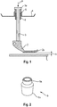
- the Fig. 1 shows a schematic representation of a region of the sewing machine according to the invention.
- FIG. 1 initially a throat plate 1, a presser foot 2, a presser foot bar 3 and a head element 4 of the sewing machine are shown.
- the sewing material is arranged on the needle plate 1 during a sewing process.
- a transporter (not shown) can be arranged under the throat plate 1, which is designed to transport the sewing material further after a stitch by the set stitch length.
- Also not shown are, for example, the needle, needle bar and transport foot.
- the presser foot 2 has the task of pressing the material to be sewn down in the direction of the needle plate 1 and holding it in its position. With a triple feed, the feed foot can then ensure that the sewing material can be fed evenly. Furthermore, the sewing material is kept taut so that a uniform stitch pattern can be obtained.
- the force transmission elements required for this and the force generating device are housed in a sewing machine head, which is in Fig. 1 is indicated as head element 4.
- the head element 4 can in particular be part of a housing of the sewing machine head.
- the head element 4 is usually located above the throat plate 1, so that the presser foot bar 3 extends from the head element 4 through the head element 4 downwards (in the direction of the throat plate 1) to the presser foot 2.
- the head element 4 has an optional guide sleeve 6 which is designed to guide the presser foot bar 3.
- the presser foot pressure P presses the presser foot 2 via the presser foot bar onto the throat plate 1. This means that there is no distance between the presser foot 2 and the throat plate 1 if there is no material to be sewn on the throat plate 1. If less pressure is to be exerted on the material to be sewn, the sewing foot pressure P has been set correspondingly lower. As described above, however, even this does not lead to the desired sewing results.
- the sewing machine therefore also has a spacer element 5.
- the spacer element 5 is sleeve-shaped. As in Fig. 1 As can be seen, the spacer element 5 is arranged above the presser foot 2 and in particular in the sewing machine head of the sewing machine.
- the presser foot bar 3 runs inside the spacer element 5 Fig. 1 shown) upper area on a stop element 3a.
- the stop element 3 a is pressed in the direction of the spacer element 5 by the presser foot pressure P and comes into contact with an upper region of the spacer element 5.
- the spacer element 5 itself is restricted in a downward direction of movement.
- a lower region of the spacer element 5 rests on the head element 4.
- resting on the guide sleeve 6 would also be conceivable.
- the guide sleeve 6 itself is designed as a spacer element 5. Then this would extend upwards longer. If a spacer element 5 is mentioned in the application, these aspects can thus also be transferred to the correspondingly modified guide sleeve 6.
- the stop element 3a does not move the spacer element 5 downwards, apart from an elastic behavior of the spacer element 5.
- the spacer element 5 thus offers a stopper structure for the stop element 3a and thus also for the presser foot bar 3 and the presser foot attached to this 2.
- a minimum distance h between the throat plate 1 and the presser foot 2 is achieved. More precisely, the minimum distance h is formed between an upper side of the throat plate 1 and an underside of the presser foot 2.
- the elastic spacer element 5 could be compressed so far that the minimum distance h is no longer formed . However, this should be regarded as an exception. This minimum distance h is reached in normal operation.
- the minimum distance h formed on the basis of the spacer element 5 prevents imprints from the presser foot 2 on the material to be sewn. Nevertheless, sufficient pressure can be exerted on the sewing material at the same time so that it cannot slip and be transported evenly.
- a friction layer 2a may be arranged, which increases the friction with the sewing material.
- the effect of the friction layer 2 a works synergistically with that of the spacer element 5.
- the spacer 5 is in Fig. 2 once again shown more clearly. It shows Fig. 2 a schematic plan view of the spacer element 5 according to the invention Spacer element 5 is sleeve-shaped and has an upper region 5a and a lower region 5b.
- the upper area 5a has an outer radius which is smaller than an outer radius of the lower area 5b.
- a transition area is formed between the two areas 5a and 5b, which connects the two outer radii to one another.
- a sleeve interior is also formed within the spacer element 5.
- the interior of the sleeve is delimited by the inner circumferential walls of the spacer element 5.
- the inner radius of the spacer element 5 can change along the length of the spacer element 5.
- the inner radius in the upper region 5a can be smaller than the inner radius in the lower region 5b.
- the wall thickness of the sleeve-shaped spacer element 5 would be uniform despite different outer radii.
- Such a spacer element 5 is particularly easy to manufacture from a tubular starting element.
- the starting material must allow a certain deformability, so that a soft metal such as brass is preferably chosen.
- the smallest inner radius of the spacer element 5 is, however, always so large that it can surround the presser foot bar 3 without interference.
- interference-free means that it still has sufficient play in the spacer element 5.
- the presser foot bar 3 can, as in Figure 1 shown, are movably arranged within the spacer element 5.
- the spacer element 5 can also have a fastening element (not shown) which is used to fasten the spacer element 5 at a fixed position within the sewing machine.
- the fastening element is preferably a threaded element.
Landscapes
- Engineering & Computer Science (AREA)
- Textile Engineering (AREA)
- Sewing Machines And Sewing (AREA)
Abstract
Description
- Die vorliegende Erfindung betrifft eine Nähmaschine, die zumindest eine Stichplatte, einen Stoffdrückerfuß und eine Drückerfußstange aufweist. Ferner betrifft die Erfindung die Verwendung eines Abstandselements in einer Nähmaschine.
- Nähmaschinen dienen allgemein zur mechanischen Herstellung einer Naht. Beispielsweise werden Nähmaschinen im Automobilbereich dazu verwendet, Lederobjekte mit Nähten oder Ziernähten zu versehen. Insbesondere werden in Fahrzeugen beispielsweise Automobilsitze, Instrumententafeln oder Türverkleidungen mit derartigen Nähten bzw. Ziernähten ausgestattet. Die Nähte bzw. Ziernähte dienen hierbei primär auch als dekoratives Element, das dem Lederobjekt einen hochwertigen optischen Eindruck verleihen soll oder einen solchen zumindest unterstützen soll.
- Dies wird allerdings nur dann erreicht, wenn die Naht einerseits optisch gleichmäßig und andererseits beständig auf das Lederobjekt aufgebracht wird, ohne das Lederobjekt hierbei zu beschädigen oder nachteilig optisch zu verändern. Bei der Verwendung der gängigen Nähmaschinen stellt allerdings insbesondere der letzte Punkt nach wie vor ein großes Problem dar.
- So weisen bekannte Nähmaschinen einen Stoffdrückerfuß auf, der dazu dient, das Lederobjekt als Nähgut zu halten, um einen genauen und gleichmäßigen Transport des auf einer Stichplatte angeordneten Nähguts unter der Nähmaschine zu gewährleisten. Dieser Stoffdrückerfuß liegt auf der Stichplatte auf, wobei ein oftmals stufenlos einstellbarer Nähfuß-Druck vorgegeben werden kann, der über eine Drückerfußstange auf den Stoffdrückerfuß wirkt. Der korrekt zu verwendende Nähfuß-Druck hängt üblicherweise von dem Nähgut ab, wobei für weiche Materialien, wie beispielsweise ein Tuch, ein geringerer Druck eingestellt wird und für feste Materialen, wie beispielsweise Leder, ein größerer Druck eingestellt wird. Bei der richtigen Einstellung des Nähfuß-Drucks verrutscht das Nähgut nicht und wird störungsfrei transportiert.
- Bei der Herstellung von Nähten auf insbesondere hochwertigen Lederobjekten reichen die derzeit für den Stoffdrückerfuß bekannten Einstellmöglichkeiten allerdings nicht aus, um ein zufriedenstellendes Ergebnis zu erzielen. Wird der Druck niedrig eingestellt, verrutscht das Nähgut und wird nicht gleichmäßig transportiert. Wird der Druck hingegen höher eingestellt, hinterlässt der Stoffdrückerfuß einen sichtbaren Abdruck auf dem Lederobjekt, so dass dieses nicht mehr den optischen Anforderungen genügt.
- Der Erfindung liegt daher die Aufgabe zugrunde, eine Nähmaschine anzugeben, die die oben genannten Probleme und Nachteile des Standes der Technik ausräumt. Insbesondere ist es Aufgabe der vorliegenden Erfindung, eine Nähmaschine anzugeben, die es ermöglicht ein Nähgut, insbesondere ein Lederobjekt, so mit Nähten zu versehen, dass das Ergebnis hohen optischen Ansprüchen gerecht wird und insbesondere keine sichtbaren Abdrücke des Stoffdrückerfußes der Nähmaschine auf dem Nähgut hinterlassen werden.
- Der Erfindung liegt ferner die Aufgabe zugrunde, ein Element für die Verwendung in Nähmaschinen anzugeben, das die obigen Probleme und Nachteile des Standes der Technik ausräumt.
- Die erfindungsgemäße Lösung besteht darin, eine Nähmaschine anzugeben, die Folgendes aufweist: eine Stichplatte, auf der ein Nähgut anordbar ist; einen Stoffdrückerfuß, der dazu ausgebildet ist, das Nähgut zu halten; und eine Drückerfußstange, an der der Stoffdrückerfuß angebracht ist, wobei die Nähmaschine ferner ein Abstandselement aufweist, wobei das Abstandselement so ausgebildet und angeordnet ist, dass das Abstandselement einen Mindestabstand h zwischen der Stichplatte und dem Stoffdrückerfuß vorgibt.
- Auf die Stichplatte kann das Nähgut, also beispielsweise ein Lederobjekt, aufgelegt werden. Der Stoffdrückerfuß ist so ausgebildet, dass er das Nähgut hält. Das bedeutet, dass das Nähgut beim Nähen nicht wegrutscht und in Richtung Stichplatte gedrückt wird. Außerdem unterstützt der Stoffdrückerfuß einen gleichmäßigen Transport des Nähguts. Dieser erfolgt beim Nähen von Leder in der Regel nach dem Dreifachtransport-Prinzip, bei dem ein hierfür ausgebildeter Transportfuß das Nähgut von oben gegen einen Transporteur drückt, der unter der Stichplatte angeordnet ist. Dieser erfasst dann das Nähgut und transportiert es weiter.
- Damit dieser Ablauf gewährleistet wird, muss über Drückerfußstange und Stoffdrückerfuß allerdings auf das Nähgut von oben Druck ausgeübt werden. Die Drückerfußstange arbeitet typischerweise unter Federdruck, so dass ein elastisches Drücken des Stoffdrückerfußes auf das Nähgut möglich ist.
- Mit der erfindungsgemäßen Nähmaschine wird die Aufgabe in zufriedenstellender Weise gelöst. Insbesondere wird durch den Mindestabstand h zwischen der Stichplatte und dem Stoffdrückerfuß erreicht, dass der Stoffdrückerfuß keinen Abdruck mehr auf dem Nähgut hinterlässt. Gleichzeitig wird das Nähgut dennoch sicher gehalten, so dass es nicht verrutscht und gleichmäßig transportiert werden kann.
- Der Mindestabstand h ist parallel zu einer Axialrichtung der Drückerfußstange zwischen Stoffdrückerfuß und Stichplatte ausgebildet.
- Gemäß einer vorteilhaften Weiterbildung der Erfindung weist die Drückerfußstange ein Anschlagelement auf, das mit dem Abstandselement in Anschlag kommt.
- Durch diesen Anschlag geben Anschlagelement und Abstandselement den Mindestabstand h vor. Bei dem Anschlagelement kann es sich beispielsweise um einen Flansch an einem dem Stoffdrückerfuß entgegengesetzten Endbereich der Drückerfußstange handeln. Häufig sind derartige Flansche ohnehin, beispielsweise zur Kraftübertragung, an dem Endbereich der Drückerfußstange ausgebildet. Alternativ kann es sich auch um einen Kragen oder ein sonstiges Element, beispielsweise ein stabförmiges Element, handeln, das nach außen hin von der Drückerfußstange aus vorsteht.
- Gemäß einer vorteilhaften Weiterbildung der Erfindung ist das Abstandselement zwischen einem Kopfelement der Nähmaschine und dem Anschlagelement der Drückerfußstange angeordnet.
- Das Kopfelement der Nähmaschine befindet sich über der Stichplatte. Bei dem Kopfelement kann es sich beispielsweise um einen Teil eines Gehäuses eines Nähmaschinenkopfes handeln.
- Alternativ oder zusätzlich hierzu wäre auch ein Aufliegen auf einer Führungshülse denkbar, die in an dem Kopfelement angeordnet ist, um die Drückerfußstange in ihrer Bewegung zu führen. Alternativ wäre es denkbar, dass die Führungshülse selbst als Abstandselement ausgebildet ist und mit dem Anschlagelement in Kontakt kommt.
- Gemäß einer vorteilhaften Weiterbildung der Erfindung ist das Abstandselement zumindest bereichsweise elastisch ausgebildet.
- Das bedeutet, dass das Abstandselement durch die von der Drückerfußstange wirkende Kraft gestaucht werden kann und die Kraft und damit den auf das Nähgut wirkenden Druck etwas abdämpft. Wenn das Abstandselement elastisch ausgebildet ist, kann es sich insbesondere um ein Federelement, beispielsweise eine Spiralfeder, handeln. Alternativ hierzu kann es sich auch um ein Hülsenelement aus einem elastischen Material handeln.
- Durch die dämpfende Wirkung des Abstandselements kann der auf das Nähgut wirkende Druck so weit verringert werden, dass der Stoffdrückerfuß keinen sichtbaren Abdruck auf dem Nähgut hinterlässt. Gleichzeitig kann der Mindestabstand h so gering gehalten werden, dass das Nähgut sicher gehalten wird und gleichmäßig transportiert werden kann.
- Gemäß einer vorteilhaften Weiterbildung der Erfindung ist das Abstandselement hülsenförmig ausgebildet, wobei die Drückerfußstange in einem Hülsen-Innenraum des Abstandselements angeordnet ist.
- Eine Hülse eignet sich besonders, um den gewünschten Mindestabstand h zwischen der Stichplatte und dem Stoffdrückerfuß vorzugeben. Der Innenradius der Hülse ist hierbei kleiner als der Außenradius der Drückerfußstange, so dass diese zwar in der Hülse geführt wird, sich allerdings auch in Axialrichtung, insbesondere von oben nach unten und umgekehrt, bewegen kann.
- Wenn die Drückerfußstange außerdem eine Anschlagelement, beispielsweise in Form eines Flansches, eines Kragens oder ähnlich, aufweist, kann der Mindestabstand h zuverlässig vorgegeben werden.
- Außerdem ist eine Hülse kostengünstig herzustellen und einfach einzubauen. Insbesondere ist eine solche auch bei bereits produzierten Maschinen einfach nachrüstbar. Als Material eignet sich insbesondere eine weiche Metalllegierung, wie beispielsweise eine Kupferlegierung, vorzugsweise Messing.
- Gemäß einer vorteilhaften Weiterbildung der Erfindung weist der Stoffdrückerfuß an einer zu der Stichplatte zeigenden Unterseite eine Reibungsschicht auf.
- Als Reibungsschicht wird eine den Reibungskoeffizienten erhöhende Schicht verstanden. Bei der Reibungsschicht kann es sich um eine Beschichtung handeln, mit der der Stoffdrückerfuß beschichtet wird. Alternativ kann es sich auch um eine Schicht im Sinne eines zusätzlichen plattenförmigen Elements handeln, das an der Unterseite des Stoffdrückerfußes angebracht ist. Als Material eignet sich insbesondere ein Gummimaterial.
- Die Reibungsschicht erhöht die Reibung zwischen Nähgut und Stoffdrückerfuß und wirkt somit einem Wegrutschen des Nähguts entgegen. Durch das Vorgeben des Mindestabstands h zwischen Stoffdrückerfuß und Stichplatte wird auch die Reibung zwischen Nähgut und Stoffdrückerfuß verringert, da eine Normalkraft erst bei Überwindung des Mindestabstands h von dem Stoffdrückerfuß auf das Nähgut wirken kann. Mittels Anordnen der Reibungsschicht kann der Reibungskoeffizient zwischen dem Stoffdrückerfuß und dem Nähgut erhöht werden, so dass dennoch ein zuverlässiges Halten des Nähguts erfolgt.
- Die erfindungsgemäße Lösung besteht ferner darin, die Verwendung eines Abstandselements in einer Nähmaschine anzugeben, um einen Mindestabstand h zwischen einer Stichplatte der Nähmaschine und einem Stoffdrückerfuß der Nähmaschine vorzugeben.
- Hierbei ergeben sich die gleichen Vorteile wie bei der erfindungsgemäßen Nähmaschine. Zu betonen ist allerdings die Nachrüstbarkeit. So ist das Abstandselement bei gängigen Nähmaschinen nachrüstbar, so dass diese einfach und kostengünstig verbessert werden können.
- Gemäß einer vorteilhaften Weiterbildung der Erfindung ist das zur Verwendung angegebene Abstandselement zumindest bereichsweise elastisch ausgebildet.
- Dadurch lässt sich das Abstandselement stauchen, so dass es den Druck dämpft, der auf das Nähgut wirkt. Hierdurch kann das Nähergebnis weiter verbessert werden.
- Gemäß einer vorteilhaften Weiterbildung der Erfindung kommt das zur Verwendung angegebene Abstandselement bei seiner Verwendung mit einem Anschlagelement einer Drückerfußstange der Nähmaschine in Anschlag.
- Dies stellt insbesondere eine gut umzusetzende Möglichkeit zum Vorgeben des Mindestabstands h dar. Insbesondere eignen sich ein Anschlag des Abstandselements mit der Drückerfußstage auf der oberen Seite und ein Anschlag mit einem Kopfelement der Nähmaschine auf der entgegengesetzten unteren Seite.
- Gemäß einer vorteilhaften Weiterbildung der Erfindung ist das zur Verwendung angegebene Abstandselement hülsenförmig ausgebildet.
- Hierdurch kann das Abstandselement bei seiner Verwendung sicher um die Drückerfußstange herum angeordnet werden. Eine zuverlässige Vorgabe des Mindestabstands h kann somit erreicht werden. Die Größe des Mindestabstands h hängt direkt von der Länge in einer Rotationsachsenrichtung des Abstandselements, insbesondere der Hülse, ab. Damit lässt sich der Mindestabstand h einfach durch die Länge der Hülse vorgeben.
- Weitere Vorteile der Erfindung gehen aus der Beschreibung und den Zeichnungen hervor.
- Die Erfindung wird nachstehend anhand der Beschreibung von Ausführungsbeispielen unter Bezugnahme auf die beiliegenden Zeichnungen näher erläutert. Dabei ergeben sich aus der nachfolgenden Beschreibung und der Gesamtheit der Patentansprüche weitere vorteilhafte Ausführungsformen und Merkmalskombinationen der Erfindung.
- Die zu der Erläuterung der Ausführungsbeispiele verwendeten Zeichnungen zeigen in:
- Fig. 1
- eine schematische Darstellung eines Bereichs der erfindungsgemäßen Nähmaschine, in dem ein erfindungsgemäßes Abstandselement angeordnet ist; und
- Fig. 2
- eine schematische Draufsicht eines erfindungsgemäßen Abstandselement.
- In den Figuren werden Richtungsangaben "oben" oder "unten" verwendet, die sich aus Sicht eines seitlich (wie in
Fig. 1 ) auf die Nähmaschine schauenden Benutzers ergeben. - Die
Fig. 1 zeigt eine schematische Darstellung eines Bereichs der erfindungsgemäßen Nähmaschine. - Im Einzelnen ist in
Figur 1 zunächst eine Stichplatte 1, ein Stoffdrückerfuß 2, eine Drückerfußstange 3 und ein Kopfelement 4 der Nähmaschine gezeigt. Auf der Stichplatte 1 wird das Nähgut bei einem Nähprozess angeordnet. Unter der Stichplatte 1 kann ein (nicht dargestellter) Transporteur angeordnet sein, der dazu ausgebildet ist, das Nähgut nach einem Stich, um die eingestellte Stichlänge weiter zu transportierten. Ebenfalls nicht dargestellt sind beispielsweise Nadel, Nadelstange und Transportfuß. - Dem Stoffdrückerfuß 2 fällt die Aufgabe zu, das Nähgut nach unten in Richtung der Stichplatte 1 zu drücken und in seiner Position zu halten. Bei einem Dreifachtransport kann dann der Transportfuß dafür sorgen, dass das Nähgut gleichmäßig transportiert werden kann. Ferner wird das Nähgut straff gehalten, damit ein gleichmäßiges Stichbild erhalten werden kann.
- Hierfür ist ein Druck nötig, der von oben auf den Stoffdrückerfuß 2 wirkt und diesen nach unten in Richtung der Stichplatte 1 drückt. Dieser Druck wird als eingezeichneter Nähfuß-Druck P über die Drückerfußstange 3 auf den Stoffdrückerfuß 2 aufgebracht. Die hierfür nötigen Kraftübertragungselemente und die Krafterzeugungseinrichtung, beispielsweise ein pneumatisches System, sind in einem Nähmaschinenkopf untergebracht, der in
Fig. 1 als Kopfelement 4 angedeutet ist. Bei dem Kopfelement 4 kann es sich insbesondere um einen Teil eines Gehäuses des Nähmaschinenkopfes handeln. - Das Kopfelement 4 befindet sich üblicherweise über der Stichplatte 1, so dass die Drückerfußstange 3 von dem Kopfelement 4 durch das Kopfelement 4 hindurch nach unten (in Richtung der Stichplatte 1) zu dem Stoffdrückerfuß 2 reicht. Hierzu weist das Kopfelement 4 eine optionale Führungshülse 6 auf, die dazu ausgebildet ist, die Drückerfußstange 3 zu führen.
- Bei den derzeit gängigen Nähmaschinen drückt der Nähfuß-Druck P den Stoffdrückerfuß 2 über die Drückerfußstange auf die Stichplatte 1. Das heißt, dass kein Abstand zwischen dem Stoffdrückerfuß 2 und der Stichplatte 1 vorhanden ist, wenn kein Nähgut auf der Stichplatte 1 angeordnet ist. Wenn weniger Druck auf das Nähgut ausgeübt werden soll, wurde der Nähfuß-Druck P entsprechend geringer eingestellt. Wie eingangs beschrieben führt selbst dies allerdings nicht zu den gewünschten Nähergebnissen.
- In
Fig. 1 weist die Nähmaschine daher außerdem ein Abstandselement 5 auf. In dieser Ausführungsform ist das Abstandselement 5 hülsenförmig ausgebildet. Wie inFig. 1 zu erkennen, ist das Abstandselement 5 über dem Stoffdrückerfuß 2 und insbesondere in dem Nähmaschinenkopf der Nähmaschine angeordnet. - Innerhalb des Abstandselements 5 verläuft die Drückerfußstange 3. Dabei weist die Drückerfußstange 3 an einem (in
Fig. 1 dargestellten) oberen Bereich ein Anschlagelement 3a auf. Das Anschlagelement 3a wird durch den Nähfuß-Druck P in Richtung des Abstandselements 5 gedrückt und kommt mit einem oberen Bereich des Abstandselements 5 in Kontakt. - Das Abstandselement 5 selbst ist in eine Bewegungsrichtung nach unten hin beschränkt. Dies kann beispielsweise, wie in
Figur 1 dargestellt, dadurch erreicht werden, dass ein unterer Bereich des Abstandselements 5 auf dem Kopfelement 4 aufliegt. Alternativ oder zusätzlich hierzu wäre auch ein Aufliegen auf der Führungshülse 6 denkbar. Weiterhin alternativ wäre es denkbar, dass die Führungshülse 6 selbst als Abstandselement 5 ausgebildet ist. Dann würde sich diese länger nach oben erstrecken. Wenn in der Anmeldung von einem Abstandselement 5 die Rede ist, können diese Aspekte somit auch auf die entsprechend abgeänderte Führungshülse 6 übertragen werden. - Zurückkommend auf das Anschlagelement 3a bedeutet dies, dass das Anschlagelement 3a das Abstandselement 5 an sich nicht nach unten bewegt, abgesehen von einem elastischen Verhalten des Abstandselements 5. Das Abstandselement 5 bietet somit eine Stopperstruktur für das Anschlagelement 3a und hiermit auch für die Drückerfußstange 3 und den an dieser angebrachten Stoffdrückerfuß 2.
- Dadurch wird ein Mindestabstand h zwischen der Stichplatte 1 und dem Stoffdrückerfuß 2 erreicht. Genauer gesagt wird der Mindestabstand h zwischen einer Oberseite der Stichplatte 1 und einer Unterseite des Stoffdrückerfußes 2 ausgebildet. Der Vollständigkeit halber wird an dieser Stelle darauf hingewiesen, dass es bei einem sehr hohen Nähfuß-Druck P und der Verwendung eines stark elastischen Abstandselements 5 dazu kommen könnte, dass das elastische Abstandselement 5 so weit zusammengedrückt wird, dass der Mindestabstand h nicht mehr ausgebildet ist. Die ist allerdings als Ausnahme zu betrachten. Im normalen Betrieb wird dieser Mindestabstand h erreicht.
- Durch den aufgrund des Abstandselements 5 ausgebildeten Mindestabstand h werden Abdrücke von dem Stoffdrückerfuß 2 auf dem Nähgut verhindert. Dennoch kann gleichzeitig ausreichend Druck auf das Nähgut ausgeübt werden, so dass dieses nicht verrutscht und gleichmäßig transportiert werden kann.
- Um das Verrutschen des Nähguts weiter zu verhindern und einen Transport zu verbessern, kann an einer Unterseite des Stoffdrückerfußes 2, wie in
Fig. 1 gezeigt, eine Reibungsschicht 2a angeordnet sein, die die Reibung mit dem Nähgut erhöht. Die Wirkung der Reibungsschicht 2a wirkt hierbei synergistisch mit der des Abstandselements 5 zusammen. - Das Abstandselement 5 ist in
Fig. 2 noch einmal deutlicher dargestellt. Dabei zeigtFig. 2 eine schematische Draufsicht des erfindungsgemäßen Abstandselements 5. Das Abstandselement 5 ist hülsenförmig ausgebildet und weist einen oberen Bereich 5a und einen unteren Bereich 5b auf. - Der obere Bereich 5a weist einen Außenradius auf, der geringer ist als ein Außenradius des unteren Bereichs 5b. Zwischen den beiden Bereichen 5a und 5b ist ein Übergangsbereich ausgebildet, der die beiden Außenradien miteinander verbindet.
- Innerhalb des Abstandselements 5 ist ferner ein Hülsen-Innenraum ausgebildet. Der Hülsen-Innenraum wird durch Innenumfangs-Wände des Abstandselements 5 begrenzt. Dabei kann sich - wie auch der Außenradius - der Innenradius des Abstandselements 5 entlang der Länge des Abstandselements 5 verändern. Insbesondere kann der Innenradius in dem oberen Bereich 5a geringer sein als der Innenradius in dem unteren Bereich 5b. Dann wäre die Wandstärke des hülsenförmigen Abstandselements 5 trotz unterschiedlicher Außenradien gleichmäßig. Ein solches Abstandselement 5 ist insbesondere einfach aus einem rohrförmigen Ausgangselement herstellbar. Dabei muss das Ausgangsmaterial eine gewisse Verformbarkeit zulassen, sodass vorzugsweise ein weiches Metall wie Messing gewählt wird.
- Der kleinste Innenradius des Abstandselements 5 ist allerdings immer so groß, dass dieser die Drückerfußstange 3 störungsfrei umgeben kann. Störungsfrei bedeutet hier, dass diese noch ausreichend Spiel in dem Abstandselement 5 hat. Die Drückerfußstange 3 kann also, wie in
Figur 1 gezeigt, bewegbar innerhalb des Abstandselements 5 angeordnet werden. - Das Abstandselement 5 kann ferner ein (nicht dargestelltes) Befestigungselement aufweisen, das dazu dient, das Abstandselement 5 an einer festgelegten Position innerhalb der Nähmaschine zu befestigen. Bei dem Befestigungselement handelt es sich vorzugsweise um ein Gewindeelement.
-
- 1
- Stichplatte
- 2
- Stoffdrückerfuß
- 2a
- Reibungsschicht
- 3
- Drückerfußstange
- 3a
- Anschlagelement
- 4
- Kopfelement
- 5
- Abstandselement
- 5a
- oberer Bereich (des Abstandselements)
- 5b
- unterer Bereich (des Abstandselements)
- 6
- Führungshülse (für die Drückerfußstange)
- h
- Mindestabstand (zwischen Stichplatte und Stoffdrückerfuß)
- P
- Nähfuß-Druck
Claims (10)
- Nähmaschine, die Folgendes aufweist:- eine Stichplatte (1), auf der ein Nähgut anordnebar ist;- einen Stoffdrückerfuß (2), der dazu ausgebildet ist, das Nähgut zu halten; und- eine Drückerfußstange (3), an der der Stoffdrückerfuß (2) angebracht ist,
dadurch gekennzeichnet, dass
die Nähmaschine ferner ein Abstandselement (5) aufweist,
wobei das Abstandselement (5) so ausgebildet und angeordnet ist, dass das Abstandselement (5) einen Mindestabstand (h) zwischen der Stichplatte (1) und dem Stoffdrückerfuß (2) vorgibt. - Nähmaschine gemäß Anspruch 1,
wobei die Drückerfußstange (3) ein Anschlagelement (3a) aufweist, das mit dem Abstandselement (5) in Anschlag kommt. - Nähmaschine gemäß Anspruch 2,
wobei das Abstandselement (5) zwischen einem Kopfelement (4) der Nähmaschine und dem Anschlagelement (3a) der Drückerfußstange (3) angeordnet ist. - Nähmaschine gemäß einem der vorherigen Ansprüche,
wobei das Abstandselement (5) zumindest bereichsweise elastisch ausgebildet ist. - Nähmaschine gemäß einem der vorherigen Ansprüche,
wobei das Abstandselement (5) hülsenförmig ausgebildet ist und wobei die Drückerfußstange (3) in einem Hülsen-Innenraum des Abstandselements (5) angeordnet ist. - Nähmaschine gemäß einem der vorherigen Ansprüche,
wobei der Stoffdrückerfuß (2) an einer zu der Stichplatte (1) zeigenden Unterseite eine Reibungsschicht (2a) aufweist. - Verwendung eines Abstandselements (5) in einer Nähmaschine, um einen Mindestabstand (h) zwischen einer Stichplatte (1) der Nähmaschine und einem Stoffdrückerfuß (2) der Nähmaschine vorzugeben.
- Verwendung eines Abstandselements (5) in einer Nähmaschine gemäß Anspruch 7, wobei das Abstandselement (5) zumindest bereichsweise elastisch ausgebildet ist.
- Verwendung eines Abstandselements (5) in einer Nähmaschine gemäß Anspruch 7 oder 8, wobei das Abstandselement (5) bei seiner Verwendung mit einem Anschlagelement (3a) einer Drückerfußstange (3) der Nähmaschine in Anschlag kommt.
- Verwendung eines Abstandselements (5) in einer Nähmaschine gemäß einem der Ansprüche 7 bis 9, wobei das Abstandselement (5) hülsenförmig ausgebildet ist.
Applications Claiming Priority (1)
| Application Number | Priority Date | Filing Date | Title |
|---|---|---|---|
| DE102019133956.1A DE102019133956B4 (de) | 2019-12-11 | 2019-12-11 | Nähmaschine mit einem abstandselement, und verwendung eines abstandselements in einer nähmaschine |
Publications (2)
| Publication Number | Publication Date |
|---|---|
| EP3835471A1 true EP3835471A1 (de) | 2021-06-16 |
| EP3835471B1 EP3835471B1 (de) | 2025-08-27 |
Family
ID=73747887
Family Applications (1)
| Application Number | Title | Priority Date | Filing Date |
|---|---|---|---|
| EP20212348.5A Active EP3835471B1 (de) | 2019-12-11 | 2020-12-08 | Nähmaschine mit einem abstandselement, und verwendung eines abstandselements in einer nähmaschine |
Country Status (3)
| Country | Link |
|---|---|
| EP (1) | EP3835471B1 (de) |
| CN (1) | CN112941737B (de) |
| DE (1) | DE102019133956B4 (de) |
Citations (3)
| Publication number | Priority date | Publication date | Assignee | Title |
|---|---|---|---|---|
| DE90984C (de) * | 1896-04-09 | 1897-03-10 | Merrick Frank Woodard | Regelbare vorrichtung zum lüften des stoffdrückers von nähmaschinen |
| DE3132044A1 (de) * | 1981-08-13 | 1983-03-03 | Pfaff Industriemaschinen Gmbh, 6750 Kaiserslautern | Stoffdrueckereinrichtung an einer naehmaschine |
| DE19918169A1 (de) * | 1999-04-21 | 2000-10-26 | Zsk Stickmasch Gmbh | Höheneinstellung eines Stoffdrückers |
Family Cites Families (10)
| Publication number | Priority date | Publication date | Assignee | Title |
|---|---|---|---|---|
| DE2943013A1 (de) * | 1978-10-30 | 1980-05-14 | Kenichi Iwamoto | Presserfussanordnung einer naehmaschine |
| DE3117140C2 (de) * | 1981-04-30 | 1984-05-17 | Maschinenfabrik Carl Zangs Ag, 4150 Krefeld | Stickmaschine |
| SE509654C2 (sv) * | 1995-03-17 | 1999-02-22 | Viking Sewing Machines Ab | Anordning i en symaskin |
| JPH1099573A (ja) * | 1996-09-30 | 1998-04-21 | Tokai Ind Sewing Mach Co Ltd | ミシン |
| DE102007052876A1 (de) * | 2007-11-07 | 2009-05-20 | Dürkopp Adler AG | Nähmaschine |
| KR101852830B1 (ko) * | 2016-06-23 | 2018-04-27 | 박보인 | 재봉기용 재봉물 이송장치 |
| CN208055597U (zh) * | 2018-01-18 | 2018-11-06 | 台州市速普机电有限公司 | 一种缝纫机抬压脚装置 |
| CN209555497U (zh) * | 2018-10-13 | 2019-10-29 | 石家庄净源特清洁制品有限公司 | 一种用于生产超细纤维清洁巾的缝纫机 |
| CN209508576U (zh) * | 2019-01-14 | 2019-10-18 | 杰克缝纫机股份有限公司 | 一种缝纫机 |
| CN209602763U (zh) * | 2019-03-13 | 2019-11-08 | 杰克缝纫机股份有限公司 | 缝纫机及缝纫机压脚 |
-
2019
- 2019-12-11 DE DE102019133956.1A patent/DE102019133956B4/de active Active
-
2020
- 2020-12-08 EP EP20212348.5A patent/EP3835471B1/de active Active
- 2020-12-08 CN CN202011453442.3A patent/CN112941737B/zh active Active
Patent Citations (3)
| Publication number | Priority date | Publication date | Assignee | Title |
|---|---|---|---|---|
| DE90984C (de) * | 1896-04-09 | 1897-03-10 | Merrick Frank Woodard | Regelbare vorrichtung zum lüften des stoffdrückers von nähmaschinen |
| DE3132044A1 (de) * | 1981-08-13 | 1983-03-03 | Pfaff Industriemaschinen Gmbh, 6750 Kaiserslautern | Stoffdrueckereinrichtung an einer naehmaschine |
| DE19918169A1 (de) * | 1999-04-21 | 2000-10-26 | Zsk Stickmasch Gmbh | Höheneinstellung eines Stoffdrückers |
Also Published As
| Publication number | Publication date |
|---|---|
| CN112941737B (zh) | 2024-08-09 |
| EP3835471B1 (de) | 2025-08-27 |
| CN112941737A (zh) | 2021-06-11 |
| DE102019133956A1 (de) | 2021-06-17 |
| DE102019133956B4 (de) | 2022-12-29 |
Similar Documents
| Publication | Publication Date | Title |
|---|---|---|
| DE1941398B2 (de) | Befestigungsstift aus spiralig aufgewickeltem Metallblech | |
| DE102010005720B3 (de) | Haspel zur Aufnahme eines Coils aus Draht oder einem rohrförmigen oder einem bandförmigen Material zur Abgabe an eine nachgeschaltete Verarbeitungsmaschine | |
| EP0132532B1 (de) | Zylinder für eine Rotationsdruckmaschine | |
| DE1602660A1 (de) | Verfahren und Maschine zur Herstellung von Rotationsformkoerpern durch Walzen | |
| DE19720546A1 (de) | Spulengehäuse für eine Nähmaschine | |
| DE9406102U1 (de) | Fadenspeicher mit Fadenabzugsbremse | |
| DE69922436T2 (de) | Haltebremse für Treibscheibenaufzug | |
| EP2145991B1 (de) | Betätigungsvorrichtung zur Bedienung einer Nähmaschine | |
| DE2432975C2 (de) | Ausleger für Tonabnehmer und Verfahren zu seiner Herstellung | |
| DE102019133956B4 (de) | Nähmaschine mit einem abstandselement, und verwendung eines abstandselements in einer nähmaschine | |
| EP3290370A1 (de) | Drahtlaufvorrichtung | |
| DE102024201272A1 (de) | Vorrichtung und Verfahren zum Steuern einer Zugspannung eines Verpackungsmittels sowie Verpackungsmaschine | |
| DE2630765A1 (de) | Fadenspannvorrichtung fuer eine naehmaschine | |
| DE3043665A1 (de) | Halte- und fuehrungsvorrichtung fuer die stoffdrueckerstange von einer naehmaschine | |
| DE2242755A1 (de) | Steuerring fuer eine haspel | |
| DE29518006U1 (de) | Abspulvorrichtung fuer Drahtspulen | |
| EP2138621B1 (de) | Nähmaschine sowie Spuleinrichtung für eine derartige Nähmaschine | |
| DE3439453A1 (de) | Feinsteuervorrichtung | |
| CH699544B1 (de) | Kettenwirkmaschine. | |
| DE1585127A1 (de) | Verbundnadel | |
| DE102010046692A1 (de) | Verfahren zum Wickeln einer Warenbahn und Dockenwickler zur Durchführung des Verfahrens | |
| EP0461332B1 (de) | Schiffchen für Stick- und Steppmaschinen | |
| DE9305070U1 (de) | Maschine zur Herstellung eines Rohrstutzens | |
| EP3330027B1 (de) | Trommel für drahtsäge | |
| DE2217522A1 (de) | Seilandrueckvorrichtung |
Legal Events
| Date | Code | Title | Description |
|---|---|---|---|
| PUAI | Public reference made under article 153(3) epc to a published international application that has entered the european phase |
Free format text: ORIGINAL CODE: 0009012 |
|
| STAA | Information on the status of an ep patent application or granted ep patent |
Free format text: STATUS: THE APPLICATION HAS BEEN PUBLISHED |
|
| AK | Designated contracting states |
Kind code of ref document: A1 Designated state(s): AL AT BE BG CH CY CZ DE DK EE ES FI FR GB GR HR HU IE IS IT LI LT LU LV MC MK MT NL NO PL PT RO RS SE SI SK SM TR |
|
| STAA | Information on the status of an ep patent application or granted ep patent |
Free format text: STATUS: REQUEST FOR EXAMINATION WAS MADE |
|
| 17P | Request for examination filed |
Effective date: 20211209 |
|
| RBV | Designated contracting states (corrected) |
Designated state(s): AL AT BE BG CH CY CZ DE DK EE ES FI FR GB GR HR HU IE IS IT LI LT LU LV MC MK MT NL NO PL PT RO RS SE SI SK SM TR |
|
| STAA | Information on the status of an ep patent application or granted ep patent |
Free format text: STATUS: EXAMINATION IS IN PROGRESS |
|
| 17Q | First examination report despatched |
Effective date: 20230919 |
|
| GRAP | Despatch of communication of intention to grant a patent |
Free format text: ORIGINAL CODE: EPIDOSNIGR1 |
|
| STAA | Information on the status of an ep patent application or granted ep patent |
Free format text: STATUS: GRANT OF PATENT IS INTENDED |
|
| INTG | Intention to grant announced |
Effective date: 20250327 |
|
| GRAS | Grant fee paid |
Free format text: ORIGINAL CODE: EPIDOSNIGR3 |
|
| GRAA | (expected) grant |
Free format text: ORIGINAL CODE: 0009210 |
|
| STAA | Information on the status of an ep patent application or granted ep patent |
Free format text: STATUS: THE PATENT HAS BEEN GRANTED |
|
| AK | Designated contracting states |
Kind code of ref document: B1 Designated state(s): AL AT BE BG CH CY CZ DE DK EE ES FI FR GB GR HR HU IE IS IT LI LT LU LV MC MK MT NL NO PL PT RO RS SE SI SK SM TR |
|
| REG | Reference to a national code |
Ref country code: GB Ref legal event code: FG4D Free format text: NOT ENGLISH |
|
| REG | Reference to a national code |
Ref country code: CH Ref legal event code: EP |
|
| REG | Reference to a national code |
Ref country code: DE Ref legal event code: R096 Ref document number: 502020011737 Country of ref document: DE |
|
| REG | Reference to a national code |
Ref country code: IE Ref legal event code: FG4D Free format text: LANGUAGE OF EP DOCUMENT: GERMAN |
|
| REG | Reference to a national code |
Ref country code: NL Ref legal event code: MP Effective date: 20250827 |
|
| PG25 | Lapsed in a contracting state [announced via postgrant information from national office to epo] |
Ref country code: IS Free format text: LAPSE BECAUSE OF FAILURE TO SUBMIT A TRANSLATION OF THE DESCRIPTION OR TO PAY THE FEE WITHIN THE PRESCRIBED TIME-LIMIT Effective date: 20251227 |
|
| PG25 | Lapsed in a contracting state [announced via postgrant information from national office to epo] |
Ref country code: NO Free format text: LAPSE BECAUSE OF FAILURE TO SUBMIT A TRANSLATION OF THE DESCRIPTION OR TO PAY THE FEE WITHIN THE PRESCRIBED TIME-LIMIT Effective date: 20251127 |
|
| REG | Reference to a national code |
Ref country code: LT Ref legal event code: MG9D |
|
| PG25 | Lapsed in a contracting state [announced via postgrant information from national office to epo] |
Ref country code: PT Free format text: LAPSE BECAUSE OF FAILURE TO SUBMIT A TRANSLATION OF THE DESCRIPTION OR TO PAY THE FEE WITHIN THE PRESCRIBED TIME-LIMIT Effective date: 20251229 |
|
| PG25 | Lapsed in a contracting state [announced via postgrant information from national office to epo] |
Ref country code: FI Free format text: LAPSE BECAUSE OF FAILURE TO SUBMIT A TRANSLATION OF THE DESCRIPTION OR TO PAY THE FEE WITHIN THE PRESCRIBED TIME-LIMIT Effective date: 20250827 |
|
| PG25 | Lapsed in a contracting state [announced via postgrant information from national office to epo] |
Ref country code: HR Free format text: LAPSE BECAUSE OF FAILURE TO SUBMIT A TRANSLATION OF THE DESCRIPTION OR TO PAY THE FEE WITHIN THE PRESCRIBED TIME-LIMIT Effective date: 20250827 Ref country code: NL Free format text: LAPSE BECAUSE OF FAILURE TO SUBMIT A TRANSLATION OF THE DESCRIPTION OR TO PAY THE FEE WITHIN THE PRESCRIBED TIME-LIMIT Effective date: 20250827 |
|
| PG25 | Lapsed in a contracting state [announced via postgrant information from national office to epo] |
Ref country code: GR Free format text: LAPSE BECAUSE OF FAILURE TO SUBMIT A TRANSLATION OF THE DESCRIPTION OR TO PAY THE FEE WITHIN THE PRESCRIBED TIME-LIMIT Effective date: 20251128 |
|
| PG25 | Lapsed in a contracting state [announced via postgrant information from national office to epo] |
Ref country code: SE Free format text: LAPSE BECAUSE OF FAILURE TO SUBMIT A TRANSLATION OF THE DESCRIPTION OR TO PAY THE FEE WITHIN THE PRESCRIBED TIME-LIMIT Effective date: 20250827 |
|
| PG25 | Lapsed in a contracting state [announced via postgrant information from national office to epo] |
Ref country code: LV Free format text: LAPSE BECAUSE OF FAILURE TO SUBMIT A TRANSLATION OF THE DESCRIPTION OR TO PAY THE FEE WITHIN THE PRESCRIBED TIME-LIMIT Effective date: 20250827 |
|
| PG25 | Lapsed in a contracting state [announced via postgrant information from national office to epo] |
Ref country code: BG Free format text: LAPSE BECAUSE OF FAILURE TO SUBMIT A TRANSLATION OF THE DESCRIPTION OR TO PAY THE FEE WITHIN THE PRESCRIBED TIME-LIMIT Effective date: 20250827 Ref country code: PL Free format text: LAPSE BECAUSE OF FAILURE TO SUBMIT A TRANSLATION OF THE DESCRIPTION OR TO PAY THE FEE WITHIN THE PRESCRIBED TIME-LIMIT Effective date: 20250827 |
|
| PG25 | Lapsed in a contracting state [announced via postgrant information from national office to epo] |
Ref country code: RS Free format text: LAPSE BECAUSE OF FAILURE TO SUBMIT A TRANSLATION OF THE DESCRIPTION OR TO PAY THE FEE WITHIN THE PRESCRIBED TIME-LIMIT Effective date: 20251127 |
|
| PG25 | Lapsed in a contracting state [announced via postgrant information from national office to epo] |
Ref country code: ES Free format text: LAPSE BECAUSE OF FAILURE TO SUBMIT A TRANSLATION OF THE DESCRIPTION OR TO PAY THE FEE WITHIN THE PRESCRIBED TIME-LIMIT Effective date: 20250827 |
|
| PG25 | Lapsed in a contracting state [announced via postgrant information from national office to epo] |
Ref country code: RO Free format text: LAPSE BECAUSE OF FAILURE TO SUBMIT A TRANSLATION OF THE DESCRIPTION OR TO PAY THE FEE WITHIN THE PRESCRIBED TIME-LIMIT Effective date: 20250827 |
|
| PG25 | Lapsed in a contracting state [announced via postgrant information from national office to epo] |
Ref country code: SM Free format text: LAPSE BECAUSE OF FAILURE TO SUBMIT A TRANSLATION OF THE DESCRIPTION OR TO PAY THE FEE WITHIN THE PRESCRIBED TIME-LIMIT Effective date: 20250827 |
|
| PG25 | Lapsed in a contracting state [announced via postgrant information from national office to epo] |
Ref country code: DK Free format text: LAPSE BECAUSE OF FAILURE TO SUBMIT A TRANSLATION OF THE DESCRIPTION OR TO PAY THE FEE WITHIN THE PRESCRIBED TIME-LIMIT Effective date: 20250827 |
|
| PG25 | Lapsed in a contracting state [announced via postgrant information from national office to epo] |
Ref country code: IT Free format text: LAPSE BECAUSE OF FAILURE TO SUBMIT A TRANSLATION OF THE DESCRIPTION OR TO PAY THE FEE WITHIN THE PRESCRIBED TIME-LIMIT Effective date: 20250827 |
|
| PG25 | Lapsed in a contracting state [announced via postgrant information from national office to epo] |
Ref country code: CZ Free format text: LAPSE BECAUSE OF FAILURE TO SUBMIT A TRANSLATION OF THE DESCRIPTION OR TO PAY THE FEE WITHIN THE PRESCRIBED TIME-LIMIT Effective date: 20250827 |
|
| PG25 | Lapsed in a contracting state [announced via postgrant information from national office to epo] |
Ref country code: EE Free format text: LAPSE BECAUSE OF FAILURE TO SUBMIT A TRANSLATION OF THE DESCRIPTION OR TO PAY THE FEE WITHIN THE PRESCRIBED TIME-LIMIT Effective date: 20250827 Ref country code: SK Free format text: LAPSE BECAUSE OF FAILURE TO SUBMIT A TRANSLATION OF THE DESCRIPTION OR TO PAY THE FEE WITHIN THE PRESCRIBED TIME-LIMIT Effective date: 20250827 |