EP3833913B1 - Eiserzeugungsanordnungen zur herstellung von klareis - Google Patents
Eiserzeugungsanordnungen zur herstellung von klareis Download PDFInfo
- Publication number
- EP3833913B1 EP3833913B1 EP19847712.7A EP19847712A EP3833913B1 EP 3833913 B1 EP3833913 B1 EP 3833913B1 EP 19847712 A EP19847712 A EP 19847712A EP 3833913 B1 EP3833913 B1 EP 3833913B1
- Authority
- EP
- European Patent Office
- Prior art keywords
- ice
- mold cavity
- mold
- water
- ice making
- Prior art date
- Legal status (The legal status is an assumption and is not a legal conclusion. Google has not performed a legal analysis and makes no representation as to the accuracy of the status listed.)
- Active
Links
Images


Classifications
-
- F—MECHANICAL ENGINEERING; LIGHTING; HEATING; WEAPONS; BLASTING
- F25—REFRIGERATION OR COOLING; COMBINED HEATING AND REFRIGERATION SYSTEMS; HEAT PUMP SYSTEMS; MANUFACTURE OR STORAGE OF ICE; LIQUEFACTION SOLIDIFICATION OF GASES
- F25C—PRODUCING, WORKING OR HANDLING ICE
- F25C1/00—Producing ice
- F25C1/12—Producing ice by freezing water on cooled surfaces, e.g. to form slabs
-
- F—MECHANICAL ENGINEERING; LIGHTING; HEATING; WEAPONS; BLASTING
- F25—REFRIGERATION OR COOLING; COMBINED HEATING AND REFRIGERATION SYSTEMS; HEAT PUMP SYSTEMS; MANUFACTURE OR STORAGE OF ICE; LIQUEFACTION SOLIDIFICATION OF GASES
- F25C—PRODUCING, WORKING OR HANDLING ICE
- F25C1/00—Producing ice
- F25C1/18—Producing ice of a particular transparency or translucency, e.g. by injecting air
-
- F—MECHANICAL ENGINEERING; LIGHTING; HEATING; WEAPONS; BLASTING
- F25—REFRIGERATION OR COOLING; COMBINED HEATING AND REFRIGERATION SYSTEMS; HEAT PUMP SYSTEMS; MANUFACTURE OR STORAGE OF ICE; LIQUEFACTION SOLIDIFICATION OF GASES
- F25C—PRODUCING, WORKING OR HANDLING ICE
- F25C1/00—Producing ice
- F25C1/04—Producing ice by using stationary moulds
- F25C1/045—Producing ice by using stationary moulds with the open end pointing downwards
-
- F—MECHANICAL ENGINEERING; LIGHTING; HEATING; WEAPONS; BLASTING
- F25—REFRIGERATION OR COOLING; COMBINED HEATING AND REFRIGERATION SYSTEMS; HEAT PUMP SYSTEMS; MANUFACTURE OR STORAGE OF ICE; LIQUEFACTION SOLIDIFICATION OF GASES
- F25C—PRODUCING, WORKING OR HANDLING ICE
- F25C1/00—Producing ice
- F25C1/22—Construction of moulds; Filling devices for moulds
- F25C1/25—Filling devices for moulds
-
- F—MECHANICAL ENGINEERING; LIGHTING; HEATING; WEAPONS; BLASTING
- F25—REFRIGERATION OR COOLING; COMBINED HEATING AND REFRIGERATION SYSTEMS; HEAT PUMP SYSTEMS; MANUFACTURE OR STORAGE OF ICE; LIQUEFACTION SOLIDIFICATION OF GASES
- F25C—PRODUCING, WORKING OR HANDLING ICE
- F25C1/00—Producing ice
- F25C1/22—Construction of moulds; Filling devices for moulds
-
- F—MECHANICAL ENGINEERING; LIGHTING; HEATING; WEAPONS; BLASTING
- F25—REFRIGERATION OR COOLING; COMBINED HEATING AND REFRIGERATION SYSTEMS; HEAT PUMP SYSTEMS; MANUFACTURE OR STORAGE OF ICE; LIQUEFACTION SOLIDIFICATION OF GASES
- F25C—PRODUCING, WORKING OR HANDLING ICE
- F25C2400/00—Auxiliary features or devices for producing, working or handling ice
- F25C2400/14—Water supply
Definitions
- the present subject matter relates generally to ice making appliances, and more particularly to appliances for making substantially clear ice.
- ice In domestic and commercial applications, ice is often formed as solid cubes, such as crescent cubes or generally rectangular blocks.
- the shape of such cubes is often dictated by the environment during a freezing process.
- an ice maker can receive liquid water, and such liquid water can freeze within the ice maker to form ice cubes.
- certain ice makers include a freezing mold that defines a plurality of cavities. The plurality of cavities can be filled with liquid water, and such liquid water can freeze within the plurality of cavities to form solid ice cubes.
- Typical solid cubes or blocks may be relatively small in order to accommodate a large number of uses, such as temporary cold storage and rapid cooling of liquids in a wide range of sizes.
- ice cubes or blocks may be useful in a variety of circumstances, there are certain conditions in which distinct or unique ice shapes may be desirable.
- relatively large ice cubes or spheres e.g., larger than two inches in diameter
- Slow melting of ice may be especially desirable in certain liquors or cocktails.
- such cubes or spheres may provide a unique or upscale impression for the user.
- ice presses have come to market.
- certain presses include metal press elements that define a profile to which a relatively large ice billet may be reshaped (e.g., in response to gravity or generated heat).
- Such systems reduce some of the dangers and user skill required when reshaping ice by hand.
- the time needed for the systems to melt an ice billet is generally contingent upon the size and shape of the initial ice billet.
- the quality (e.g., clarity) of the final solid cube or block may be dependent on the quality of the initial ice billet.
- impurities and gases may be trapped within the billet.
- impurities and gases may collect near the outer regions of the ice billet due to their inability to escape and as a result of the freezing liquid to solid phase change of the ice cube surfaces.
- a dull or cloudy finish may form on the exterior surfaces of an ice billet (e.g., during rapid freezing of the ice cube).
- a cloudy or opaque ice billet is the resulting product of typical ice making appliances.
- US 3 043 117 A discloses an ice making assembly according to the preamble of claim 1.
- an ice making assembly in one exemplary aspect of the present disclosure, includes a conductive ice mold, an insulation jacket, a sealed refrigeration system, and a water dispenser.
- the conductive ice mold defines an upper portion of a mold cavity extending from a top end to a bottom end.
- the insulation jacket extends downward from the conductive ice mold.
- the insulation jacket defines a lower portion of the mold cavity.
- the lower portion of the mold cavity is a vertically open passage aligned with the upper portion of the mold cavity.
- the sealed refrigeration system includes an evaporator in conductive thermal communication with the conductive ice mold above the insulation jacket.
- the water dispenser is positioned below the insulation jacket to direct an ice-building spray of water to the mold cavity through the vertically open passage of the insulation jacket.
- controller may be configured to alternately initiate the ice-building spray and a discrete ice-reducing to the mold cavity.
- the ice-reducing spray may be initiated subsequent to and separate from the ice-building spray.
- the terms “first,” “second,” and “third” may be used interchangeably to distinguish one component from another and are not intended to signify location or importance of the individual components.
- upstream and downstream refer to the relative flow direction with respect to fluid flow in a fluid pathway.
- upstream refers to the flow direction from which the fluid flows
- downstream refers to the flow direction to which the fluid flows.
- the terms “includes” and “including” are intended to be inclusive in a manner similar to the term “comprising.”
- the term “or” is generally intended to be inclusive (i.e., "A or B” is intended to mean “A or B or both”).
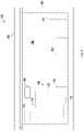
- FIG. 1 provides a side plan view of an ice making appliance 100, including an ice making assembly 102.
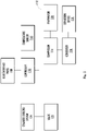
- FIG. 2 provides a schematic view of ice making assembly 102.
- FIG. 3 provides a simplified perspective view of ice making assembly 102.
- ice making appliance 100 includes a cabinet 104 (e.g., insulated housing) and defines a mutually orthogonal vertical direction V, lateral direction, and transverse direction.
- the lateral direction and transverse direction may be generally understood to be horizontal directions H.
- cabinet 104 defines one or more chilled chambers, such as a freezer chamber 106.
- ice making appliance 100 is understood to be formed as, or as part of, a stand-alone freezer appliance. It is recognized, however, that additional or alternative examples may be provided within the context of other refrigeration appliances.
- a refrigerator appliance e.g., a top mount refrigerator appliance, a bottom mount refrigerator appliance, a side-by-side style refrigerator appliance, etc.
- a freezer chamber e.g., a refrigerator appliance that includes a freezer chamber.
- Ice making appliance 100 generally includes an ice making assembly 102 on or within freezer chamber 106.
- ice making appliance 100 includes a door 105 that is rotatably attached to cabinet 104 (e.g., at a top portion thereof).
- door 105 may selectively cover an opening defined by cabinet 104.
- door 105 may rotate on cabinet 104 between an open position (not pictured) permitting access to freezer chamber 106 and a closed position ( FIG. 2 ) restricting access to freezer chamber 106.
- a user interface panel 108 is provided for controlling the mode of operation.
- user interface panel 108 may include a plurality of user inputs (not labeled), such as a touchscreen or button interface, for selecting a desired mode of operation.
- Operation of ice making appliance 100 can be regulated by a controller 110 that is operatively coupled to user interface panel 108 or various other components, as will be described below.
- User interface panel 108 provides selections for user manipulation of the operation of ice making appliance 100 such as (e.g., selections regarding chamber temperature, ice making speed, or other various options).
- controller 110 may operate various components of the ice making appliance 100 or ice making assembly 102.
- Controller 110 may include a memory (e.g., non-transitive memory) and one or more microprocessors, CPUs or the like, such as general or special purpose microprocessors operable to execute programming instructions or micro-control code associated with operation of ice making appliance 100.
- the memory may represent random access memory such as DRAM, or read only memory such as ROM or FLASH.
- the processor executes programming instructions stored in memory.
- the memory may be a separate component from the processor or may be included onboard within the processor.
- controller 110 may be constructed without using a microprocessor (e.g., using a combination of discrete analog or digital logic circuitry; such as switches, amplifiers, integrators, comparators, flip-flops, AND gates, and the like; to perform control functionality instead of relying upon software).
- a microprocessor e.g., using a combination of discrete analog or digital logic circuitry; such as switches, amplifiers, integrators, comparators, flip-flops, AND gates, and the like; to perform control functionality instead of relying upon software).
- Controller 110 may be positioned in a variety of locations throughout ice making appliance 100. In optional embodiments, controller 110 is located within the user interface panel 108. In other embodiments, the controller 110 may be positioned at any suitable location within ice making appliance 100, such as for example within cabinet 104. Input/output ("I/O") signals may be routed between controller 110 and various operational components of ice making appliance 100. For example, user interface panel 108 may be in communication with controller 110 via one or more signal lines or shared communication busses.
- controller 110 may be in communication with the various components of ice making assembly 102 and may control operation of the various components. For example, various valves, switches, etc. may be actuatable based on commands from the controller 110. As discussed, user interface panel 108 may additionally be in communication with the controller 110. Thus, the various operations may occur based on user input or automatically through controller 110 instruction.
- ice making appliance 100 includes a sealed refrigeration system 112 for executing a vapor compression cycle for cooling water within ice making appliance 100 (e.g., within freezer chamber 106).
- Sealed refrigeration system 112 includes a compressor 114, a condenser 116, an expansion device 118, and an evaporator 120 connected in fluid series and charged with a refrigerant.
- sealed refrigeration system 112 may include additional components (e.g., one or more directional flow valves or an additional evaporator, compressor, expansion device, or condenser).
- At least one component e.g., evaporator 120
- evaporator 120 is provided in thermal communication (e.g., conductive thermal communication) with an ice mold or mold assembly 130 ( FIG. 3 ) to cool mold assembly 130, such as during ice making operations.
- evaporator 120 is mounted within freezer chamber 106, as generally illustrated in FIG. 1 .
- gaseous refrigerant flows into compressor 114, which operates to increase the pressure of the refrigerant.
- This compression of the refrigerant raises its temperature, which is lowered by passing the gaseous refrigerant through condenser 116.
- condenser 116 heat exchange with ambient air takes place so as to cool the refrigerant and cause the refrigerant to condense to a liquid state.
- Expansion device 118 receives liquid refrigerant from condenser 116. From expansion device 118, the liquid refrigerant enters evaporator 120. Upon exiting expansion device 118 and entering evaporator 120, the liquid refrigerant drops in pressure and vaporizes. Due to the pressure drop and phase change of the refrigerant, evaporator 120 is cool relative to freezer chamber 106. As such, cooled water and ice or air is produced and refrigerates ice making appliance 100 or freezer chamber 106. Thus, evaporator 120 is a heat exchanger which transfers heat from water or air in thermal communication with evaporator 120 to refrigerant flowing through evaporator 120.
- evaporator 120 is a heat exchanger which transfers heat from water or air in thermal communication with evaporator 120 to refrigerant flowing through evaporator 120.
- one or more directional valves may be provided (e.g., between compressor 114 and condenser 116) to selectively redirect refrigerant through a bypass line connecting the directional valve or valves to a point in the fluid circuit downstream from the expansion device 118 and upstream from the evaporator 120.
- the one or more directional valves may permit refrigerant to selectively bypass the condenser 116 and expansion device 120.
- ice making appliance 100 further includes a valve 122 for regulating a flow of liquid water to ice making assembly 102.
- valve 122 may be selectively adjustable between an open configuration and a closed configuration. In the open configuration, valve 122 permits a flow of liquid water to ice making assembly 102 (e.g., to a water dispenser 132 or a water basin 134 of ice making assembly 102). Conversely, in the closed configuration, valve 122 hinders the flow of liquid water to ice making assembly 102.
- ice making appliance 100 also includes a discrete chamber cooling system 124 (e.g., separate from sealed refrigeration system 112) to generally draw heat from within freezer chamber 106.
- discrete chamber cooling system 124 may include a corresponding sealed refrigeration circuit (e.g., including a unique compressor, condenser, evaporator, and expansion device) or air handler (e.g., axial fan, centrifugal fan, etc.) configured to motivate a flow of chilled air within freezer chamber 106.
- one or more sensors are mounted on or within ice mold 130.
- a temperature sensor 144 may be mounted adjacent to ice mold 130. Temperature sensor 144 may be electrically coupled to controller 110 and configured to detect the temperature within ice mold 130. Temperature sensor 144 may be formed as any suitable temperature detecting device, such as a thermocouple, thermistor, etc.
- FIG. 4 provides a cross-sectional, schematic view of ice making assembly 102.
- ice making assembly 102 includes a mold assembly 130 that defines a mold cavity 136 within which an ice billet 138 may be formed.
- a plurality of mold cavities 136 may be defined by mold assembly 130 and spaced apart from each other (e.g., perpendicular to the vertical direction V).
- One or more portions of sealed refrigeration system 112 may be in thermal communication with mold assembly 130.
- evaporator 120 may be placed on or in contact (e.g., conductive contact) with a portion of mold assembly 130. During use, evaporator 120 may selectively draw heat from mold cavity 136, as will be further described below.
- a water dispenser 132 positioned below mold assembly 130 may selectively direct the flow of water into mold cavity 136.
- water dispenser 132 includes a water pump 140 and at least one nozzle 142 directed (e.g., vertically) toward mold cavity 136.
- water dispenser 132 may include a plurality of nozzles 142 or fluid pumps vertically aligned with the plurality mold cavities 136. For instance, each mold cavity 136 may be vertically aligned with a discrete nozzle 142.
- a water basin 134 is positioned below the ice mold (e.g., directly beneath mold cavity 136 along the vertical direction V).
- Water basin 134 includes a solid nonpermeable body and may define a vertical opening 145 and interior volume 146 in fluid communication with mold cavity 136. When assembled, fluids, such as excess water falling from mold cavity 136, may pass into interior volume 146 of water basin 134 through vertical opening 145.
- one or more portions of water dispenser 132 are positioned within water basin 134 (e.g., within interior volume 146).
- water pump 140 may be mounted within water basin 134 in fluid communication with interior volume 146. Thus, water pump 140 may selectively draw water from interior volume 146 (e.g., to be dispensed by spray nozzle 142).
- Nozzle 142 may extend (e.g., vertically) from water pump 140 through interior volume 146.
- a guide ramp 148 is positioned between mold assembly 130 and water basin 134 along the vertical direction V.
- guide ramp 148 may include a ramp surface that extends at a negative angle (e.g., relative to a horizontal direction) from a location beneath mold cavity 136 to another location spaced apart from water basin 134 (e.g., horizontally).
- guide ramp 148 extends to or terminates above an ice bin 150.
- guide ramp 148 may define a perforated portion 152 that is, for example, vertically aligned between mold cavity 136 and nozzle 142 or between mold cavity 136 and interior volume 146.
- One or more apertures are generally defined through guide ramp 148 at perforated portion 152. Fluids, such as water, may thus generally pass through perforated portion 152 of guide ramp 148 (e.g., along the vertical direction between mold cavity 136 and interior volume 146).
- ice bin 150 generally defines a storage volume 154 and may be positioned below mold assembly 130 and mold cavity 136. Ice billets 138 formed within mold cavity 136 may be expelled from mold assembly 130 and subsequently stored within storage volume 154 of ice bin 150 (e.g., within freezer chamber 106). In some such examples, ice bin 150 is positioned within freezer chamber 106 and horizontally spaced apart from water basin 134, water dispenser 132, or mold assembly 130. Guide ramp 148 may span the horizontal distance between mold assembly 130 and ice bin 150. As ice billets 138 descend or fall from mold cavity 136, the ice billets 138 may thus be motivated (e.g., by gravity) toward ice bin 150.
- FIGS. 5 and 6 illustrate portions of ice making assembly 102 during exemplary ice forming operations ( FIG. 5 ) and releasing operations ( FIG. 6 ).
- mold assembly 130 is formed from discrete conductive ice mold 160 and insulation jacket 162.
- insulation jacket 162 extends downward from (e.g., directly from) conductive ice mold 160.
- insulation jacket 162 may be fixed to conductive ice mold 160 through one or more suitable adhesives or attachment fasteners (e.g., bolts, latches, mated prongs-channels, etc.) positioned or formed between conductive ice mold 160 and insulation jacket 162.
- conductive ice mold 160 and insulation jacket 162 may define mold cavity 136.
- conductive ice mold 160 may define an upper portion 136A of mold cavity 136 while insulation jacket 162 defines a lower portion 136B of mold cavity 136.
- Upper portion 136A of mold cavity 136 may extend between a nonpermeable top end 164 and an open bottom end 166.
- upper portion 136A of mold cavity 136 may be curved (e.g., hemispherical) in open fluid communication with lower portion 136B of mold cavity 136.
- Lower portion 136B of mold cavity 136 may be a vertically open passage that is aligned (e.g., in the vertical direction V) with upper portion 136A of mold cavity 136.
- mold cavity 136 may extend along the vertical direction between a mold opening 168 at a bottom portion or bottom surface 170 of insulation jacket 162 to top end 164 within conductive ice mold 160.
- mold cavity 136 defines a constant diameter or horizontal width from lower portion 136B to upper portion 136A.
- fluids such as water may pass to upper portion 136A of mold cavity 136 through lower portion 136B of mold cavity 136 (e.g., after flowing through the bottom opening defined by insulation jacket 162).
- Conductive ice mold 160 and insulation jacket 162 are formed, at least in part, from two different materials.
- Conductive ice mold 160 is generally formed from a thermally conductive material (e.g., metal, such as aluminum or stainless steel, including alloys thereof) while insulation jacket 162 is generally formed from a thermally insulating material (e.g., insulating polymer, such as a synthetic silicone configured for use within subfreezing temperatures without significant deterioration).
- conductive ice mold 160 is formed from material having a greater amount of water surface adhesion than the material from which insulation jacket 162 is formed. Water freezing within mold cavity 136 may be prevented from extending horizontally along bottom surface 170 of insulation jacket 162.
- an ice billet within mold cavity 136 may be prevented from mushrooming beyond the bounds of mold cavity 136.
- ice making assembly 102 may advantageously prevent a connecting layer of ice from being formed along the bottom surface 170 of insulation jacket 162 between the separate mold cavities 136 (and ice billets therein). Further advantageously, the present examples may ensure an even heat distribution across an ice billet within mold cavity 136. Cracking of the ice billet or formation of a concave dimple at the bottom of the ice billet may thus be prevented.
- the unique materials of conductive ice mold 160 and insulation jacket 162 each extend to the surfaces defining upper portion 136A and lower portion 136B of mold cavity 136.
- a material having a relatively high water adhesion may define the bounds of upper portion 136A of mold cavity 136 while a material having a relatively low water adhesion defines the bounds of lower portion 136B of mold cavity 136.
- the surface of insulation jacket 162 defining the bounds of lower portion 136B of mold cavity 136 may be formed from an insulating polymer (e.g., silicone).
- the surface of conductive mold cavity 136 defining the bounds of upper portion 136A of mold cavity 136 may be formed from a thermally conductive metal (e.g. aluminum). In some such embodiments, the thermally conductive metal of conductive ice mold 160 may extend along (e.g., the entirety of) of upper portion 136A.
- the material or materials defining the bounds of upper portion 136A of mold cavity 136 and lower portion 136B of mold cavity 136 may both have a relatively low water adhesion.
- an insulation film 172 may extend along and define the bounds of upper portion 136A of mold cavity 136.
- insulation film 172 may extend along an inner surface of conductive ice mold 160 at upper portion 136A of mold cavity 136.
- Insulation film 172 extends from insulation jacket 162 (e.g., as a unitary or monolithic integral unit with insulation jacket 162).
- the material which forms insulation film 172 may be the same as the material that defines the bounds of lower portion 136B of mold cavity 136.
- a plurality of fluid channels 174 are defined through insulation jacket 162.
- the plurality of fluid channels 174 extends through insulation jacket 162 to lower portion 136B of mold cavity 136.
- each fluid channel 174 may define an outlet 176 above mold opening 168.
- One or more of fluid channels 174 may extend at an angle that is nonparallel to the vertical direction V. For instance, channels may be perpendicular to the vertical direction V.
- fluid channels 174 may be in fluid communication with one or more fluid pumps and fluid sources to direct a fluid therefrom as an ice-reducing spray (e.g., as indicated at arrows 182).
- the fluid channels 174 are in fluid communication with a water pump (e.g., water pump 140 within water basin 134).
- Water pump 140 may be configured to direct a water flow to lower portion 136B of mold cavity 136.
- At least a portion of the ice-reducing spray 182 may thus be a water spray to partially melt an ice billet within mold cavity 136 and encourage an ice billet to release from mold cavity 136.
- One or more of fluid channels 174 are in fluid communication with an air pump 180 (e.g., in fluid communication with a compressed or ambient air source).
- the air pump 180 may be configured to direct an airflow to lower portion 136B of mold cavity 136. At least a portion of the ice-reducing spray 182 may thus be an air spray to partially melt and ice billet within mold cavity 136 and encourage an ice billet to release from mold cavity 136.
- controller 110 may be in communication (e.g., electrical communication) with one or more portions of ice making assembly 102.
- controller 110 is in communication with one or more fluid pumps (e.g., water pump 140 or air pump 180).
- Controller 110 may be configured to initiate discrete ice making operations and ice release operations. For instance, controller 110 may alternate the fluid source spray to mold cavity 136.
- controller 110 may initiate or direct water dispenser 132 to motivate an ice-building spray (e.g., as indicated at arrows 184) through nozzle 142 and into mold cavity 136 (e.g., through mold opening 168). Controller 110 may further direct sealed refrigeration system 112 (e.g., at compressor 114) ( FIG. 3 ) to motivate refrigerant through evaporator 120 and draw heat from within mold cavity 136. As the water from the ice-building spray 184 strikes mold assembly 130 within mold cavity 136, a portion of the water may freeze in progressive layers from top end 164 to bottom end 166.
- sealed refrigeration system 112 e.g., at compressor 114
- Excess water e.g., water within mold cavity 136 that does not freeze upon contact with mold assembly 130 or the frozen volume herein
- impurities within the ice-building spray 184 may fall from mold cavity 136 and, for example, to water basin 134.
- controller 110 may direct an ice release operation. During release operations, controller 110 may halt or prevent the ice-building spray 184 and initiate a discrete ice-reducing spray 182 to mold cavity 136. In other words, the ice-reducing spray 182 may be subsequent to and separate from the ice-building spray 184. Optionally, controller 110 may restrict or halt operation of sealed refrigeration system 112 (e.g., at compressor 114) ( FIG. 3 ) during release operations. Accordingly, the ice-reducing spray 182 flows from plurality of fluid channels 174.
- sealed refrigeration system 112 e.g., at compressor 114
- the ice-reducing spray 182 may be formed from a flow of water or air motivated from a fluid pump (e.g., water pump 140 or air pump 180), as described above.
- the ice-reducing spray 182 may be formed from a flow of water motivated from water dispenser 132.
- nozzle 142 is configured to vary or alternate a spray pattern of water therefrom.
- the spray pattern from nozzle 142 at the ice-building spray 184 may be unique and distinct from the spray pattern from nozzle 142 at the ice-reducing spray 182.
- the ice-reducing spray 182 may be motivated by and from the same pump or a separate pump as the fluid pump which motivates the ice-building spray 184. As the ice-reducing spray 182 flows to a portion of an ice billet within mold cavity 136, the ice billet may separate from mold assembly 130 and fall from mold cavity 136 through mold opening 168 (e.g., as motivated by gravity).
Landscapes
- Engineering & Computer Science (AREA)
- Physics & Mathematics (AREA)
- Mechanical Engineering (AREA)
- Thermal Sciences (AREA)
- General Engineering & Computer Science (AREA)
- Production, Working, Storing, Or Distribution Of Ice (AREA)
Claims (7)
- Eiserzeugungsanordnung (102), umfassend:eine leitfähige Eisform (160), die einen oberen Abschnitt (136A) eines Formhohlraumes (136), der sich von einem oberen Ende (164) zu einem unteren Ende (166) erstreckt, definiert;eine Isolierummantelung (162), die sich von der leitfähigen Eisform (160) nach unten erstreckt, wobei die Isolierummantelung (162) einen unteren Abschnitt (136B) des Formhohlraumes (136) definiert, wobei der untere Abschnitt (136B) des Formhohlraumes (136) ein vertikal offener Durchlass ist, der mit dem oberen Abschnitt (136A) des Formhohlraumes (136) ausgerichtet ist;ein abgedichtetes Kühlsystem (112), das einen Verdampfer (120), der in wärmeleitfähiger Verbindung mit der leitfähigen Eisform (160) steht, über der Isolierummantelung (162) umfasst; undeinen Wasserspender (132), der unter der Isolierummantelung (162) befindlich ist, um einen eisformenden Sprühnebel (184) aus Wasser durch den vertikal offenen Durchlass der Isolierummantelung (162) hindurch in den Formhohlraum (136) zu führen, dadurch gekennzeichnet, dass eine Mehrzahl von Fluidkanälen (174) durch die Isolierummantelung (162) hindurch in den unteren Abschnitt (136B) des Formhohlraumes (136) definiert ist, und wobei die Mehrzahl von Fluidkanälen (174) mit einer Fluidpumpe in Fluidverbindung steht, um einen eisreduzierenden Sprühnebel (182) aus Fluid in den unteren Abschnitt (136B) des Formhohlraumes (136) zu führen.
- Eiserzeugungsanordnung (102) nach Anspruch 1, ferner umfassend:eine Wasserwanne (134), die unter der leitfähigen Eisform (160) befindlich ist, um überschüssiges Wasser von dem eisformenden Sprühnebel (184) aufzunehmen; und/odereine Eiswanne (150), die unter der leitfähigen Eisform (160) befindlich ist, um Eis daraus aufzunehmen.
- Eiserzeugungsanordnung (102) nach Anspruch 1, wobei die Isolierummantelung (162) ein isolierendes Polymer umfasst, das den unteren Abschnitt (136B) des Formhohlraumes (136) definiert,
wobei die leitfähige Eisform (160) Aluminium umfasst, das sich entlang des oberen Abschnitts (136A) des Formhohlraumes (136) erstreckt. - Eiserzeugungsanordnung (102) nach Anspruch 1, ferner umfassend einen Isolierfilm (172), der sich von der Isolierummantelung (162) entlang einer inneren Oberfläche der leitfähigen Eisform (160) an dem oberen Abschnitt (136A) des Formhohlraumes (136) erstreckt.
- Eiserzeugungsanordnung (102) nach Anspruch 1, wobei die Fluidpumpe eine Luftpumpe ist, die dazu ausgestaltet ist, einen Luftstrom in den unteren Abschnitt (136B) des Formhohlraumes (136) zu führen.
- Eiserzeugungsanordnung (102) nach Anspruch 1, wobei die Fluidpumpe eine Wasserpumpe ist, die dazu ausgestaltet ist, einen Wasserstrom in den unteren Abschnitt (136B) des Formhohlraumes (136) zu führen,
wobei die Eiserzeugungsanordnung (102) ferner eine Steuerung (110) umfasst, die dazu ausgestaltet ist, Wasser abwechselnd zu dem Wasserspender (132) und zu der Mehrzahl von Fluidkanälen (174) zu führen. - Eiserzeugungsanordnung (102) nach Anspruch 1, ferner umfassend eine Steuerung (110), die dazu ausgestaltet ist, abwechselnd den eisformenden Sprühnebel (184) und einen diskreten eisreduzierenden Sprühnebel (182) in den Formhohlraum (136) zu veranlassen, wobei der eisreduzierende Sprühnebel (182) nach und getrennt von dem eisformenden Sprühnebel (184) veranlasst wird.
Priority Applications (1)
| Application Number | Priority Date | Filing Date | Title |
|---|---|---|---|
| EP22176232.1A EP4177547B1 (de) | 2018-08-06 | 2019-08-06 | Eiserzeugungsanordnungen zur herstellung von klareis |
Applications Claiming Priority (2)
| Application Number | Priority Date | Filing Date | Title |
|---|---|---|---|
| US16/055,244 US10801768B2 (en) | 2018-08-06 | 2018-08-06 | Ice making assemblies for making clear ice |
| PCT/CN2019/099396 WO2020029948A1 (en) | 2018-08-06 | 2019-08-06 | Ice making assemblies for making clear ice |
Related Child Applications (1)
| Application Number | Title | Priority Date | Filing Date |
|---|---|---|---|
| EP22176232.1A Division EP4177547B1 (de) | 2018-08-06 | 2019-08-06 | Eiserzeugungsanordnungen zur herstellung von klareis |
Publications (3)
| Publication Number | Publication Date |
|---|---|
| EP3833913A1 EP3833913A1 (de) | 2021-06-16 |
| EP3833913A4 EP3833913A4 (de) | 2021-11-03 |
| EP3833913B1 true EP3833913B1 (de) | 2022-06-29 |
Family
ID=69227418
Family Applications (2)
| Application Number | Title | Priority Date | Filing Date |
|---|---|---|---|
| EP19847712.7A Active EP3833913B1 (de) | 2018-08-06 | 2019-08-06 | Eiserzeugungsanordnungen zur herstellung von klareis |
| EP22176232.1A Active EP4177547B1 (de) | 2018-08-06 | 2019-08-06 | Eiserzeugungsanordnungen zur herstellung von klareis |
Family Applications After (1)
| Application Number | Title | Priority Date | Filing Date |
|---|---|---|---|
| EP22176232.1A Active EP4177547B1 (de) | 2018-08-06 | 2019-08-06 | Eiserzeugungsanordnungen zur herstellung von klareis |
Country Status (4)
| Country | Link |
|---|---|
| US (1) | US10801768B2 (de) |
| EP (2) | EP3833913B1 (de) |
| CN (1) | CN112567190B (de) |
| WO (1) | WO2020029948A1 (de) |
Families Citing this family (21)
| Publication number | Priority date | Publication date | Assignee | Title |
|---|---|---|---|---|
| KR102823935B1 (ko) | 2018-11-16 | 2025-06-23 | 엘지전자 주식회사 | 아이스 메이커 및 이를 구비하는 냉장고 |
| KR102696156B1 (ko) * | 2018-12-12 | 2024-08-19 | 엘지전자 주식회사 | 아이스 머신 |
| US11255593B2 (en) * | 2019-06-19 | 2022-02-22 | Haier Us Appliance Solutions, Inc. | Ice making assembly including a sealed system for regulating the temperature of the ice mold |
| US11391501B2 (en) * | 2019-07-17 | 2022-07-19 | Haier Us Appliance Solutions, Inc. | Modulator for an ice maker |
| WO2021092108A1 (en) | 2019-11-06 | 2021-05-14 | Abstract Ice, Inc. | Systems and methods for creating clear ice |
| US11009281B1 (en) * | 2020-07-15 | 2021-05-18 | Haier Us Appliance Solutions, Inc. | Ice making assemblies and removable nozzles therefor |
| WO2022077347A1 (en) * | 2020-10-15 | 2022-04-21 | Haier Us Appliance Solutions, Inc. | Flow rate control method for an ice making assembly |
| US20240027118A1 (en) * | 2020-11-20 | 2024-01-25 | Abstract Ice, Inc. | Devices for producing clear ice products and related methods |
| US11874051B2 (en) * | 2021-02-15 | 2024-01-16 | Courtright Engineering Company, Llc | Ice ball press |
| WO2023279354A1 (en) * | 2021-07-09 | 2023-01-12 | Haier Us Appliance Solutions, Inc. | Evaporator for an ice making assembly |
| US20230027053A1 (en) * | 2021-07-21 | 2023-01-26 | Haier Us Appliance Solutions, Inc. | Clear ice making systems and methods |
| US11859886B2 (en) * | 2021-08-11 | 2024-01-02 | Haier Us Appliance Solutions, Inc. | Ice making assemblies for making clear ice |
| EP4224096B1 (de) * | 2021-12-24 | 2025-02-12 | Intyco Co., Ltd. | System zur herstellung von transparentem eis und herstellungsverfahren dafür |
| US12196473B2 (en) * | 2022-04-18 | 2025-01-14 | Haier Us Appliance Solutions, Inc. | Refrigerator appliance having an air-cooled clear ice making assembly |
| TWM633089U (zh) * | 2022-05-26 | 2022-10-11 | 沛豐能源科技股份有限公司 | 冰球之製造裝置 |
| US12571573B2 (en) | 2022-11-21 | 2026-03-10 | Abstract Ice, Inc. | Devices for producing clear ice products |
| US20240247852A1 (en) * | 2023-01-23 | 2024-07-25 | Haier Us Appliance Solutions, Inc. | Refrigerator and ice-making assembly and methods for reliably forming clear ice |
| US12326287B2 (en) * | 2023-01-23 | 2025-06-10 | Haier Us Appliance Solutions, Inc. | Refrigerator and ice-making assembly for making and holding clear ice billets |
| US12209786B2 (en) * | 2023-01-23 | 2025-01-28 | Haier Us Appliance Solutions, Inc. | Refrigerator and ice-making assembly having a removable water basin |
| AU2024215251A1 (en) | 2023-02-02 | 2025-08-14 | Abstract Ice, Inc. | Devices for shaping clear ice products and related methods |
| CN116907148B (zh) * | 2023-07-10 | 2024-03-19 | 哈尔滨工程大学 | 一种透明冰制冰机 |
Family Cites Families (86)
| Publication number | Priority date | Publication date | Assignee | Title |
|---|---|---|---|---|
| US1996050A (en) * | 1932-09-13 | 1935-03-26 | George L Pownall | Method for making table ice |
| US2145773A (en) * | 1933-11-08 | 1939-01-31 | Muffly Glenn | Refrigerator and method and apparatus for freezing ice |
| US2145774A (en) * | 1934-04-05 | 1939-01-31 | Muffly Glenn | Apparatus for freezing ice |
| US2488529A (en) * | 1944-06-05 | 1949-11-22 | Flakice Corp | Method and apparatus for making ice |
| US2542892A (en) * | 1947-10-01 | 1951-02-20 | Icecrafter Trust | Machine for manufacturing ice |
| US2593874A (en) * | 1948-10-29 | 1952-04-22 | Flakice Corp | Ice-making |
| US2612030A (en) * | 1950-05-13 | 1952-09-30 | Servel Inc | Refrigeration |
| US2645095A (en) * | 1950-05-13 | 1953-07-14 | Servel Inc | Automatic icemaking machine |
| US2613506A (en) * | 1950-05-13 | 1952-10-14 | Servel Inc | Ice-making machine |
| US2999371A (en) * | 1950-07-01 | 1961-09-12 | Carrier Corp | Ice cube makers |
| US2656686A (en) * | 1951-08-04 | 1953-10-27 | John R Bayston | Ice-making machine |
| US2677249A (en) * | 1951-09-18 | 1954-05-04 | Sabra E Mason | Apparatus for forming ice cubes |
| US2729070A (en) * | 1952-06-28 | 1956-01-03 | Ward A Ames | Ice cube machine |
| US2995905A (en) * | 1952-08-25 | 1961-08-15 | Whirlpool Co | Ice cube forming machine |
| US2743588A (en) * | 1953-03-05 | 1956-05-01 | Servel Inc | Ice maker |
| US2723536A (en) * | 1953-03-18 | 1955-11-15 | Sabra E Mason | Apparatus for forming ice cubes |
| US2722110A (en) * | 1953-05-06 | 1955-11-01 | Romeo S Denzer | Ice cube maker |
| US2747375A (en) * | 1953-05-14 | 1956-05-29 | Gen Motors Corp | Ice making apparatus |
| US2746262A (en) * | 1954-01-11 | 1956-05-22 | Albert M Gallo | Ice making machine |
| US2740265A (en) * | 1954-05-03 | 1956-04-03 | John R Bayston | Machine for manufacturing ice cubes |
| US2791103A (en) * | 1954-05-25 | 1957-05-07 | Hooper Kimball & Williams Inc | Controls for an ice making machine |
| US2866322A (en) * | 1954-07-20 | 1958-12-30 | Muffly Glenn | Refrigerator and ice maker |
| US2892323A (en) * | 1954-11-09 | 1959-06-30 | Glenn E Woodmark | Ice cube making machine |
| US2763993A (en) * | 1954-11-16 | 1956-09-25 | John R Bayston Trustee Icecraf | Ice cube manufacturing apparatus |
| US2805557A (en) * | 1955-03-21 | 1957-09-10 | Raymond G Hilger | Ice making unit |
| US2834189A (en) * | 1955-05-27 | 1958-05-13 | Carbonic Dispenser Inc | Ice cube making machine |
| US3009336A (en) * | 1956-09-04 | 1961-11-21 | John R Bayston | Ice making machine |
| US2997861A (en) * | 1958-10-17 | 1961-08-29 | Vilter Manufacturing Corp | Art of producing ice briquettes |
| US2978882A (en) * | 1959-09-24 | 1961-04-11 | Dwight L Bollefer | Ice cube making machine |
| US3045438A (en) * | 1960-07-05 | 1962-07-24 | Carrier Corp | Ice making |
| US3045443A (en) * | 1960-07-05 | 1962-07-24 | Carrier Corp | Ice making |
| US3045439A (en) * | 1960-07-05 | 1962-07-24 | Carrier Corp | Grid and platen ice making |
| US3003335A (en) * | 1960-07-22 | 1961-10-10 | Kattis Theodore | Ice making machine |
| US3043117A (en) * | 1960-10-28 | 1962-07-10 | Kodiak Inc | Freezing mold for ice cube making machines |
| US3062018A (en) * | 1961-01-30 | 1962-11-06 | Jess F Baker | Method and apparatus for defrosting ice cubing machines |
| US3171266A (en) * | 1961-07-06 | 1965-03-02 | Weisco Products Corp | Ice making machine with water distribution means |
| US3106072A (en) * | 1961-10-03 | 1963-10-08 | Muffly Glenn | Refrigerator-freezer |
| US3220214A (en) * | 1963-06-13 | 1965-11-30 | Cornelius Co | Spray type ice cube maker |
| US3171267A (en) * | 1963-07-01 | 1965-03-02 | Clifford F Mitchell | Ice cube making machine having removable ice cube molds |
| US3230736A (en) * | 1963-11-13 | 1966-01-25 | Whirlpool Co | Plate type evaporator for ice slabs |
| US3164972A (en) * | 1964-01-06 | 1965-01-12 | Whirlpool Co | Mounting for ice maker cutting grid |
| US3289430A (en) * | 1964-03-27 | 1966-12-06 | Manitowoc Co | Spray type ice cube making machine |
| US3277661A (en) * | 1965-04-20 | 1966-10-11 | Square Cube Corp | Ice cube making machine |
| US3386258A (en) * | 1967-02-06 | 1968-06-04 | Alfred E. Zygiel | Spray type icemaker |
| US3423952A (en) * | 1967-03-10 | 1969-01-28 | Lloyd R Pugh | Ice making apparatus |
| US3465537A (en) * | 1967-09-12 | 1969-09-09 | King Seeley Thermos Co | Icemaker using condenser cooling water as thawing medium |
| GB1244831A (en) * | 1967-09-29 | 1971-09-02 | Winget Ltd | Ice making apparatus |
| US4008740A (en) * | 1974-09-03 | 1977-02-22 | Chermack Robert W | Dispensing apparatus for filling drinking containers |
| US4142678A (en) * | 1977-07-11 | 1979-03-06 | Bottum Edward W | Combined heat pump system and ice making system |
| US4363220A (en) * | 1981-09-25 | 1982-12-14 | Ripley Wayne H | Ice making apparatus |
| US4602489A (en) * | 1984-12-18 | 1986-07-29 | Hoshizaki Electric Co., Ltd. | Automatic ice making machine |
| US4942742A (en) * | 1986-04-23 | 1990-07-24 | Burruel Sergio G | Ice making apparatus |
| US4910974A (en) * | 1988-01-29 | 1990-03-27 | Hoshizaki Electric Company Limited | Automatic ice making machine |
| US4899548A (en) * | 1989-02-17 | 1990-02-13 | Berge A. Dimijian | Ice forming apparatus |
| US4970877A (en) | 1989-02-17 | 1990-11-20 | Berge A. Dimijian | Ice forming apparatus |
| DE19538026A1 (de) * | 1995-10-12 | 1997-04-17 | Josef Hobelsberger | Vorrichtung zur Erzeugung von Eisstücken |
| US5606869A (en) * | 1996-04-08 | 1997-03-04 | Joo; Sung I. | Cylindrical ice cube maker |
| JP4289708B2 (ja) * | 1998-12-28 | 2009-07-01 | 三洋電機株式会社 | 逆セル型製氷機 |
| US6311501B1 (en) * | 1999-11-11 | 2001-11-06 | Scotsman Ice Systems | Ice machine water distribution and cleaning system and method |
| JP3834183B2 (ja) * | 2000-04-12 | 2006-10-18 | ホシザキ電機株式会社 | オープンセルタイプ自動製氷機 |
| AU8260601A (en) * | 2000-09-01 | 2002-03-13 | Katsuzo Somura | Method and apparatus for producing stereoscopic ice of transparent sphere or thelike |
| JP2003042608A (ja) * | 2001-07-30 | 2003-02-13 | Matsushita Refrig Co Ltd | 製氷装置 |
| JP2003042619A (ja) * | 2001-07-30 | 2003-02-13 | Matsushita Refrig Co Ltd | 製氷装置 |
| US6681580B2 (en) * | 2001-09-12 | 2004-01-27 | Manitowoc Foodservice Companies, Inc. | Ice machine with assisted harvest |
| JP2003262442A (ja) | 2002-03-06 | 2003-09-19 | Hoshizaki Electric Co Ltd | 縦形製氷機 |
| JP2004325064A (ja) * | 2003-04-11 | 2004-11-18 | Hoshizaki Electric Co Ltd | 製氷機の製氷機構 |
| TWI335407B (en) * | 2003-12-19 | 2011-01-01 | Hoshizaki Electric Co Ltd | Automatic ice making machine |
| US7437885B2 (en) * | 2004-10-26 | 2008-10-21 | Whirlpool Corporation | Water spillage management for in the door ice maker |
| US7661275B2 (en) * | 2005-10-06 | 2010-02-16 | Mile High Equipment L.L.C. | Ice making method and machine with PETD harvest |
| US7665316B2 (en) * | 2005-10-25 | 2010-02-23 | Japan Servo Co., Ltd. | Automatic icemaker |
| US7444828B2 (en) * | 2005-11-30 | 2008-11-04 | Hoshizaki Denki Kabushiki Kaisha | Ice discharging structure of ice making mechanism |
| CN101460792A (zh) * | 2006-09-01 | 2009-06-17 | 星崎电机株式会社 | 流下式制冰机 |
| CN100412472C (zh) * | 2006-10-16 | 2008-08-20 | 戴进军 | 制冰机的水循环机构 |
| JP5097459B2 (ja) * | 2007-06-22 | 2012-12-12 | ホシザキ電機株式会社 | 製氷機の運転方法 |
| JP5052277B2 (ja) * | 2007-09-26 | 2012-10-17 | ホシザキ電機株式会社 | 自動製氷機の製氷水タンク |
| CN102221276B (zh) * | 2011-05-17 | 2013-01-09 | 合肥美的荣事达电冰箱有限公司 | 一种用于冰箱的制冰装置和具有其的冰箱 |
| US20130186113A1 (en) * | 2012-01-20 | 2013-07-25 | Pepsico, Inc. | Method and Apparatus for Ice Harvesting |
| US20140047859A1 (en) * | 2012-08-14 | 2014-02-20 | Kyle E. E. Schwulst | System For Forming Frozen Liquids |
| US9080800B2 (en) * | 2012-12-13 | 2015-07-14 | Whirlpool Corporation | Molded clear ice spheres |
| US9074803B2 (en) * | 2012-12-13 | 2015-07-07 | Whirlpool Corporation | Clear ice spheres |
| US9200823B2 (en) * | 2012-12-13 | 2015-12-01 | Whirlpool Corporation | Ice maker with thermoelectrically cooled mold for producing spherical clear ice |
| AU2014201376B2 (en) * | 2013-03-15 | 2016-07-14 | Manitowoc Foodservice Companies, Llc | A method and system for controlling the initiation of a freeze cycle pre-set time in an ice maker |
| JP6089974B2 (ja) | 2013-05-30 | 2017-03-08 | 株式会社デンソー | 電力線通信システム、マスタ及びスレーブ |
| US9528737B2 (en) * | 2013-10-31 | 2016-12-27 | Pepsico, Inc. | Ice making and harvesting |
| JP2015190707A (ja) | 2014-03-28 | 2015-11-02 | ホシザキ電機株式会社 | クローズドセル式の自動製氷機 |
| CN103913026A (zh) * | 2014-04-03 | 2014-07-09 | 广州高野能源科技有限公司 | 制冰机脱冰装置及其脱冰工艺 |
-
2018
- 2018-08-06 US US16/055,244 patent/US10801768B2/en active Active
-
2019
- 2019-08-06 EP EP19847712.7A patent/EP3833913B1/de active Active
- 2019-08-06 WO PCT/CN2019/099396 patent/WO2020029948A1/en not_active Ceased
- 2019-08-06 EP EP22176232.1A patent/EP4177547B1/de active Active
- 2019-08-06 CN CN201980053054.5A patent/CN112567190B/zh active Active
Also Published As
| Publication number | Publication date |
|---|---|
| EP4177547A1 (de) | 2023-05-10 |
| US10801768B2 (en) | 2020-10-13 |
| WO2020029948A1 (en) | 2020-02-13 |
| EP3833913A4 (de) | 2021-11-03 |
| CN112567190A (zh) | 2021-03-26 |
| US20200041186A1 (en) | 2020-02-06 |
| CN112567190B (zh) | 2022-07-22 |
| EP4177547B1 (de) | 2023-11-22 |
| EP3833913A1 (de) | 2021-06-16 |
Similar Documents
| Publication | Publication Date | Title |
|---|---|---|
| EP3833913B1 (de) | Eiserzeugungsanordnungen zur herstellung von klareis | |
| EP3988872B1 (de) | Eisbereitungsanlage | |
| US10788250B2 (en) | Ice making assemblies and methods for making clear ice | |
| US11009281B1 (en) | Ice making assemblies and removable nozzles therefor | |
| EP4030126B1 (de) | Verdampferanordnung für eisbereiter | |
| US12188707B2 (en) | Evaporator for an ice making assembly | |
| US20240247852A1 (en) | Refrigerator and ice-making assembly and methods for reliably forming clear ice | |
| US12196473B2 (en) | Refrigerator appliance having an air-cooled clear ice making assembly | |
| WO2022099601A1 (en) | Ice mold for a clear ice making assembly | |
| US11859886B2 (en) | Ice making assemblies for making clear ice | |
| US11920845B2 (en) | Flow rate control method for an ice making assembly | |
| US12209786B2 (en) | Refrigerator and ice-making assembly having a removable water basin | |
| US12326287B2 (en) | Refrigerator and ice-making assembly for making and holding clear ice billets | |
| US11988432B2 (en) | Refrigerator appliance having an air-cooled clear ice making assembly |
Legal Events
| Date | Code | Title | Description |
|---|---|---|---|
| STAA | Information on the status of an ep patent application or granted ep patent |
Free format text: STATUS: THE INTERNATIONAL PUBLICATION HAS BEEN MADE |
|
| PUAI | Public reference made under article 153(3) epc to a published international application that has entered the european phase |
Free format text: ORIGINAL CODE: 0009012 |
|
| STAA | Information on the status of an ep patent application or granted ep patent |
Free format text: STATUS: REQUEST FOR EXAMINATION WAS MADE |
|
| 17P | Request for examination filed |
Effective date: 20210305 |
|
| AK | Designated contracting states |
Kind code of ref document: A1 Designated state(s): AL AT BE BG CH CY CZ DE DK EE ES FI FR GB GR HR HU IE IS IT LI LT LU LV MC MK MT NL NO PL PT RO RS SE SI SK SM TR |
|
| STAA | Information on the status of an ep patent application or granted ep patent |
Free format text: STATUS: EXAMINATION IS IN PROGRESS |
|
| A4 | Supplementary search report drawn up and despatched |
Effective date: 20210930 |
|
| RIC1 | Information provided on ipc code assigned before grant |
Ipc: F25C 1/04 20180101AFI20210924BHEP |
|
| 17Q | First examination report despatched |
Effective date: 20211012 |
|
| DAV | Request for validation of the european patent (deleted) | ||
| DAX | Request for extension of the european patent (deleted) | ||
| GRAP | Despatch of communication of intention to grant a patent |
Free format text: ORIGINAL CODE: EPIDOSNIGR1 |
|
| STAA | Information on the status of an ep patent application or granted ep patent |
Free format text: STATUS: GRANT OF PATENT IS INTENDED |
|
| INTG | Intention to grant announced |
Effective date: 20220407 |
|
| GRAS | Grant fee paid |
Free format text: ORIGINAL CODE: EPIDOSNIGR3 |
|
| GRAA | (expected) grant |
Free format text: ORIGINAL CODE: 0009210 |
|
| STAA | Information on the status of an ep patent application or granted ep patent |
Free format text: STATUS: THE PATENT HAS BEEN GRANTED |
|
| AK | Designated contracting states |
Kind code of ref document: B1 Designated state(s): AL AT BE BG CH CY CZ DE DK EE ES FI FR GB GR HR HU IE IS IT LI LT LU LV MC MK MT NL NO PL PT RO RS SE SI SK SM TR |
|
| REG | Reference to a national code |
Ref country code: CH Ref legal event code: EP |
|
| REG | Reference to a national code |
Ref country code: AT Ref legal event code: REF Ref document number: 1501598 Country of ref document: AT Kind code of ref document: T Effective date: 20220715 |
|
| REG | Reference to a national code |
Ref country code: IE Ref legal event code: FG4D |
|
| REG | Reference to a national code |
Ref country code: DE Ref legal event code: R096 Ref document number: 602019016567 Country of ref document: DE |
|
| REG | Reference to a national code |
Ref country code: LT Ref legal event code: MG9D |
|
| PG25 | Lapsed in a contracting state [announced via postgrant information from national office to epo] |
Ref country code: SE Free format text: LAPSE BECAUSE OF FAILURE TO SUBMIT A TRANSLATION OF THE DESCRIPTION OR TO PAY THE FEE WITHIN THE PRESCRIBED TIME-LIMIT Effective date: 20220629 Ref country code: NO Free format text: LAPSE BECAUSE OF FAILURE TO SUBMIT A TRANSLATION OF THE DESCRIPTION OR TO PAY THE FEE WITHIN THE PRESCRIBED TIME-LIMIT Effective date: 20220929 Ref country code: LT Free format text: LAPSE BECAUSE OF FAILURE TO SUBMIT A TRANSLATION OF THE DESCRIPTION OR TO PAY THE FEE WITHIN THE PRESCRIBED TIME-LIMIT Effective date: 20220629 Ref country code: HR Free format text: LAPSE BECAUSE OF FAILURE TO SUBMIT A TRANSLATION OF THE DESCRIPTION OR TO PAY THE FEE WITHIN THE PRESCRIBED TIME-LIMIT Effective date: 20220629 Ref country code: GR Free format text: LAPSE BECAUSE OF FAILURE TO SUBMIT A TRANSLATION OF THE DESCRIPTION OR TO PAY THE FEE WITHIN THE PRESCRIBED TIME-LIMIT Effective date: 20220930 Ref country code: FI Free format text: LAPSE BECAUSE OF FAILURE TO SUBMIT A TRANSLATION OF THE DESCRIPTION OR TO PAY THE FEE WITHIN THE PRESCRIBED TIME-LIMIT Effective date: 20220629 Ref country code: BG Free format text: LAPSE BECAUSE OF FAILURE TO SUBMIT A TRANSLATION OF THE DESCRIPTION OR TO PAY THE FEE WITHIN THE PRESCRIBED TIME-LIMIT Effective date: 20220929 |
|
| REG | Reference to a national code |
Ref country code: NL Ref legal event code: MP Effective date: 20220629 |
|
| REG | Reference to a national code |
Ref country code: AT Ref legal event code: MK05 Ref document number: 1501598 Country of ref document: AT Kind code of ref document: T Effective date: 20220629 |
|
| PG25 | Lapsed in a contracting state [announced via postgrant information from national office to epo] |
Ref country code: RS Free format text: LAPSE BECAUSE OF FAILURE TO SUBMIT A TRANSLATION OF THE DESCRIPTION OR TO PAY THE FEE WITHIN THE PRESCRIBED TIME-LIMIT Effective date: 20220629 Ref country code: LV Free format text: LAPSE BECAUSE OF FAILURE TO SUBMIT A TRANSLATION OF THE DESCRIPTION OR TO PAY THE FEE WITHIN THE PRESCRIBED TIME-LIMIT Effective date: 20220629 |
|
| PG25 | Lapsed in a contracting state [announced via postgrant information from national office to epo] |
Ref country code: NL Free format text: LAPSE BECAUSE OF FAILURE TO SUBMIT A TRANSLATION OF THE DESCRIPTION OR TO PAY THE FEE WITHIN THE PRESCRIBED TIME-LIMIT Effective date: 20220629 |
|
| PG25 | Lapsed in a contracting state [announced via postgrant information from national office to epo] |
Ref country code: SM Free format text: LAPSE BECAUSE OF FAILURE TO SUBMIT A TRANSLATION OF THE DESCRIPTION OR TO PAY THE FEE WITHIN THE PRESCRIBED TIME-LIMIT Effective date: 20220629 Ref country code: SK Free format text: LAPSE BECAUSE OF FAILURE TO SUBMIT A TRANSLATION OF THE DESCRIPTION OR TO PAY THE FEE WITHIN THE PRESCRIBED TIME-LIMIT Effective date: 20220629 Ref country code: RO Free format text: LAPSE BECAUSE OF FAILURE TO SUBMIT A TRANSLATION OF THE DESCRIPTION OR TO PAY THE FEE WITHIN THE PRESCRIBED TIME-LIMIT Effective date: 20220629 Ref country code: PT Free format text: LAPSE BECAUSE OF FAILURE TO SUBMIT A TRANSLATION OF THE DESCRIPTION OR TO PAY THE FEE WITHIN THE PRESCRIBED TIME-LIMIT Effective date: 20221031 Ref country code: ES Free format text: LAPSE BECAUSE OF FAILURE TO SUBMIT A TRANSLATION OF THE DESCRIPTION OR TO PAY THE FEE WITHIN THE PRESCRIBED TIME-LIMIT Effective date: 20220629 Ref country code: EE Free format text: LAPSE BECAUSE OF FAILURE TO SUBMIT A TRANSLATION OF THE DESCRIPTION OR TO PAY THE FEE WITHIN THE PRESCRIBED TIME-LIMIT Effective date: 20220629 Ref country code: AT Free format text: LAPSE BECAUSE OF FAILURE TO SUBMIT A TRANSLATION OF THE DESCRIPTION OR TO PAY THE FEE WITHIN THE PRESCRIBED TIME-LIMIT Effective date: 20220629 |
|
| PG25 | Lapsed in a contracting state [announced via postgrant information from national office to epo] |
Ref country code: PL Free format text: LAPSE BECAUSE OF FAILURE TO SUBMIT A TRANSLATION OF THE DESCRIPTION OR TO PAY THE FEE WITHIN THE PRESCRIBED TIME-LIMIT Effective date: 20220629 Ref country code: IS Free format text: LAPSE BECAUSE OF FAILURE TO SUBMIT A TRANSLATION OF THE DESCRIPTION OR TO PAY THE FEE WITHIN THE PRESCRIBED TIME-LIMIT Effective date: 20221029 |
|
| REG | Reference to a national code |
Ref country code: DE Ref legal event code: R097 Ref document number: 602019016567 Country of ref document: DE |
|
| PG25 | Lapsed in a contracting state [announced via postgrant information from national office to epo] |
Ref country code: MC Free format text: LAPSE BECAUSE OF FAILURE TO SUBMIT A TRANSLATION OF THE DESCRIPTION OR TO PAY THE FEE WITHIN THE PRESCRIBED TIME-LIMIT Effective date: 20220629 Ref country code: AL Free format text: LAPSE BECAUSE OF FAILURE TO SUBMIT A TRANSLATION OF THE DESCRIPTION OR TO PAY THE FEE WITHIN THE PRESCRIBED TIME-LIMIT Effective date: 20220629 |
|
| REG | Reference to a national code |
Ref country code: CH Ref legal event code: PL |
|
| PG25 | Lapsed in a contracting state [announced via postgrant information from national office to epo] |
Ref country code: LU Free format text: LAPSE BECAUSE OF NON-PAYMENT OF DUE FEES Effective date: 20220806 Ref country code: LI Free format text: LAPSE BECAUSE OF NON-PAYMENT OF DUE FEES Effective date: 20220831 Ref country code: DK Free format text: LAPSE BECAUSE OF FAILURE TO SUBMIT A TRANSLATION OF THE DESCRIPTION OR TO PAY THE FEE WITHIN THE PRESCRIBED TIME-LIMIT Effective date: 20220629 Ref country code: CZ Free format text: LAPSE BECAUSE OF FAILURE TO SUBMIT A TRANSLATION OF THE DESCRIPTION OR TO PAY THE FEE WITHIN THE PRESCRIBED TIME-LIMIT Effective date: 20220629 Ref country code: CH Free format text: LAPSE BECAUSE OF NON-PAYMENT OF DUE FEES Effective date: 20220831 |
|
| REG | Reference to a national code |
Ref country code: BE Ref legal event code: MM Effective date: 20220831 |
|
| PLBE | No opposition filed within time limit |
Free format text: ORIGINAL CODE: 0009261 |
|
| STAA | Information on the status of an ep patent application or granted ep patent |
Free format text: STATUS: NO OPPOSITION FILED WITHIN TIME LIMIT |
|
| 26N | No opposition filed |
Effective date: 20230330 |
|
| PG25 | Lapsed in a contracting state [announced via postgrant information from national office to epo] |
Ref country code: IE Free format text: LAPSE BECAUSE OF NON-PAYMENT OF DUE FEES Effective date: 20220806 |
|
| PG25 | Lapsed in a contracting state [announced via postgrant information from national office to epo] |
Ref country code: SI Free format text: LAPSE BECAUSE OF FAILURE TO SUBMIT A TRANSLATION OF THE DESCRIPTION OR TO PAY THE FEE WITHIN THE PRESCRIBED TIME-LIMIT Effective date: 20220629 |
|
| PG25 | Lapsed in a contracting state [announced via postgrant information from national office to epo] |
Ref country code: BE Free format text: LAPSE BECAUSE OF NON-PAYMENT OF DUE FEES Effective date: 20220831 |
|
| PG25 | Lapsed in a contracting state [announced via postgrant information from national office to epo] |
Ref country code: IT Free format text: LAPSE BECAUSE OF FAILURE TO SUBMIT A TRANSLATION OF THE DESCRIPTION OR TO PAY THE FEE WITHIN THE PRESCRIBED TIME-LIMIT Effective date: 20220629 |
|
| PG25 | Lapsed in a contracting state [announced via postgrant information from national office to epo] |
Ref country code: CY Free format text: LAPSE BECAUSE OF FAILURE TO SUBMIT A TRANSLATION OF THE DESCRIPTION OR TO PAY THE FEE WITHIN THE PRESCRIBED TIME-LIMIT Effective date: 20220629 |
|
| PG25 | Lapsed in a contracting state [announced via postgrant information from national office to epo] |
Ref country code: MK Free format text: LAPSE BECAUSE OF FAILURE TO SUBMIT A TRANSLATION OF THE DESCRIPTION OR TO PAY THE FEE WITHIN THE PRESCRIBED TIME-LIMIT Effective date: 20220629 Ref country code: HU Free format text: LAPSE BECAUSE OF FAILURE TO SUBMIT A TRANSLATION OF THE DESCRIPTION OR TO PAY THE FEE WITHIN THE PRESCRIBED TIME-LIMIT; INVALID AB INITIO Effective date: 20190806 |
|
| PG25 | Lapsed in a contracting state [announced via postgrant information from national office to epo] |
Ref country code: TR Free format text: LAPSE BECAUSE OF FAILURE TO SUBMIT A TRANSLATION OF THE DESCRIPTION OR TO PAY THE FEE WITHIN THE PRESCRIBED TIME-LIMIT Effective date: 20220629 |
|
| PG25 | Lapsed in a contracting state [announced via postgrant information from national office to epo] |
Ref country code: MT Free format text: LAPSE BECAUSE OF FAILURE TO SUBMIT A TRANSLATION OF THE DESCRIPTION OR TO PAY THE FEE WITHIN THE PRESCRIBED TIME-LIMIT Effective date: 20220629 |
|
| PG25 | Lapsed in a contracting state [announced via postgrant information from national office to epo] |
Ref country code: BG Free format text: LAPSE BECAUSE OF FAILURE TO SUBMIT A TRANSLATION OF THE DESCRIPTION OR TO PAY THE FEE WITHIN THE PRESCRIBED TIME-LIMIT Effective date: 20220629 |
|
| PG25 | Lapsed in a contracting state [announced via postgrant information from national office to epo] |
Ref country code: BG Free format text: LAPSE BECAUSE OF FAILURE TO SUBMIT A TRANSLATION OF THE DESCRIPTION OR TO PAY THE FEE WITHIN THE PRESCRIBED TIME-LIMIT Effective date: 20220629 |
|
| PGFP | Annual fee paid to national office [announced via postgrant information from national office to epo] |
Ref country code: DE Payment date: 20250812 Year of fee payment: 7 |
|
| PGFP | Annual fee paid to national office [announced via postgrant information from national office to epo] |
Ref country code: GB Payment date: 20250826 Year of fee payment: 7 |
|
| PGFP | Annual fee paid to national office [announced via postgrant information from national office to epo] |
Ref country code: FR Payment date: 20250828 Year of fee payment: 7 |