EP3832018A1 - Asphalt finisher - Google Patents
Asphalt finisher Download PDFInfo
- Publication number
- EP3832018A1 EP3832018A1 EP19844096.8A EP19844096A EP3832018A1 EP 3832018 A1 EP3832018 A1 EP 3832018A1 EP 19844096 A EP19844096 A EP 19844096A EP 3832018 A1 EP3832018 A1 EP 3832018A1
- Authority
- EP
- European Patent Office
- Prior art keywords
- contractible
- screed
- extensible
- asphalt finisher
- light
- Prior art date
- Legal status (The legal status is an assumption and is not a legal conclusion. Google has not performed a legal analysis and makes no representation as to the accuracy of the status listed.)
- Granted
Links
Images


Classifications
-
- E—FIXED CONSTRUCTIONS
- E01—CONSTRUCTION OF ROADS, RAILWAYS, OR BRIDGES
- E01C—CONSTRUCTION OF, OR SURFACES FOR, ROADS, SPORTS GROUNDS, OR THE LIKE; MACHINES OR AUXILIARY TOOLS FOR CONSTRUCTION OR REPAIR
- E01C19/00—Machines, tools or auxiliary devices for preparing or distributing paving materials, for working the placed materials, or for forming, consolidating, or finishing the paving
- E01C19/48—Machines, tools or auxiliary devices for preparing or distributing paving materials, for working the placed materials, or for forming, consolidating, or finishing the paving for laying-down the materials and consolidating them, or finishing the surface, e.g. slip forms therefor, forming kerbs or gutters in a continuous operation in situ
-
- B—PERFORMING OPERATIONS; TRANSPORTING
- B60—VEHICLES IN GENERAL
- B60Q—ARRANGEMENT OF SIGNALLING OR LIGHTING DEVICES, THE MOUNTING OR SUPPORTING THEREOF OR CIRCUITS THEREFOR, FOR VEHICLES IN GENERAL
- B60Q1/00—Arrangement of optical signalling or lighting devices, the mounting or supporting thereof or circuits therefor
- B60Q1/02—Arrangement of optical signalling or lighting devices, the mounting or supporting thereof or circuits therefor the devices being primarily intended to illuminate the way ahead or to illuminate other areas of way or environments
- B60Q1/24—Arrangement of optical signalling or lighting devices, the mounting or supporting thereof or circuits therefor the devices being primarily intended to illuminate the way ahead or to illuminate other areas of way or environments for lighting other areas than only the way ahead
-
- B—PERFORMING OPERATIONS; TRANSPORTING
- B60—VEHICLES IN GENERAL
- B60Q—ARRANGEMENT OF SIGNALLING OR LIGHTING DEVICES, THE MOUNTING OR SUPPORTING THEREOF OR CIRCUITS THEREFOR, FOR VEHICLES IN GENERAL
- B60Q1/00—Arrangement of optical signalling or lighting devices, the mounting or supporting thereof or circuits therefor
- B60Q1/26—Arrangement of optical signalling or lighting devices, the mounting or supporting thereof or circuits therefor the devices being primarily intended to indicate the vehicle, or parts thereof, or to give signals, to other traffic
- B60Q1/2615—Arrangement of optical signalling or lighting devices, the mounting or supporting thereof or circuits therefor the devices being primarily intended to indicate the vehicle, or parts thereof, or to give signals, to other traffic mounted on the vehicle body, e.g. with magnets
-
- B—PERFORMING OPERATIONS; TRANSPORTING
- B60—VEHICLES IN GENERAL
- B60Q—ARRANGEMENT OF SIGNALLING OR LIGHTING DEVICES, THE MOUNTING OR SUPPORTING THEREOF OR CIRCUITS THEREFOR, FOR VEHICLES IN GENERAL
- B60Q2800/00—Features related to particular types of vehicles not otherwise provided for
- B60Q2800/20—Utility vehicles, e.g. for agriculture, construction work
-
- E—FIXED CONSTRUCTIONS
- E01—CONSTRUCTION OF ROADS, RAILWAYS, OR BRIDGES
- E01C—CONSTRUCTION OF, OR SURFACES FOR, ROADS, SPORTS GROUNDS, OR THE LIKE; MACHINES OR AUXILIARY TOOLS FOR CONSTRUCTION OR REPAIR
- E01C2301/00—Machine characteristics, parts or accessories not otherwise provided for
- E01C2301/14—Extendable screeds
Definitions
- the present disclosure relates to an asphalt finisher.
- Patent Document 1 an asphalt finisher provided with lighting facilities has been known (see Patent Document 1).
- the lighting facilities are configured to illuminate work areas during night work.
- Patent Document 1 Japanese Laid-Open Patent Application No. 2004-116448
- the lighting facilities described above are not configured to illuminate parts protruding out of the width of a tractor, such as a bucket and a screed. Therefore, the parts protruding out of the width of the tractor may not be visible from the surroundings.
- An asphalt finisher includes a tractor; a protruding part protruding out of a width of the tractor; and a light emitting part arranged consecutively or separately on the protruding part.
- an asphalt finisher that can improve the visibility of the parts protruding out of the width of the tractor is provided.
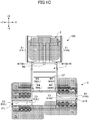
- FIGs. 1A to 1C illustrate an example of an asphalt finisher 100 as an example of a road machine according to an embodiment of the present invention.
- FIG. 1A is a side view of the asphalt finisher 100
- FIGs. 1B and 1C are top views of the asphalt finisher 100.
- the coarsest dot patterns AP in FIG. 1B indicate surfaces of existing pavement or the like
- a cross pattern NP indicates a new pavement.
- the asphalt finisher 100 is primarily constituted with a tractor 1, a hopper 2, and a screed 3.
- the direction of the hopper 2 viewed from the tractor 1 (+X direction) is assumed to be the front
- the direction of the screed 3 viewed from the tractor 1 (-X direction) is assumed to be the rear.
- the tractor 1 is a mechanism for causing the asphalt finisher 100 to travel.
- the tractor 1 rotates rear wheels 5 by using rear-wheel traction motors, and rotates front wheels 6 by using front-wheel traction motors, to move the asphalt finisher 100.
- the rear-wheel traction motors and the front-wheel traction motors receive supply of hydraulic oil from the hydraulic pump, to rotate.
- the rear wheels 5 and the front wheels 6 may be replaced with crawlers.
- a controller 50 is a control device to control the asphalt finisher 100.
- the controller 50 is constituted with an arithmetic/logic processing device including a CPU, a volatile storage device, and a non-volatile storage device, and installed in the tractor 1.
- Various functions of the controller 50 are implemented by the CPU executing programs stored in the non-volatile storage device.
- the hopper 2 is a mechanism for receiving paving materials.
- the hopper 2 is arranged in front of the tractor 1, and includes hopper wings 2W.
- the hopper wings 2W are configured to be capable of being opened and closed in the Y-axis direction (the vehicle-width direction) by hopper cylinders 24.
- the hopper wings 2W include a left hopper wing 2WL and a right hopper wing 2WR
- the hopper cylinders 24 include a left hopper cylinder 24L and a right hopper cylinder 24R.
- the left hopper wing 2WL is configured to be capable of being opened and closed by the left hopper cylinder 24L in the Y-axis direction (the vehicle-width direction)
- the right hopper wing 2WR is configured to be capable of being opened and closed by the right hopper cylinder 24R in the Y-axis direction (the vehicle-width direction).
- the asphalt finisher 100 normally receives a paving material (e.g., an asphalt mixture) from the bed of a dump truck with the hopper wings 2W in a fully opened state.
- FIGs. 1A to 1C illustrate the hopper wings 2W in a fully opened state.
- the paving material in the hopper 2 decreases, the hopper wings 2W are closed, and the paving material remaining near the inner walls of the hopper wings 2W is collected to be gathered at the center of the hopper 2.
- This is to allow a conveyor CV at the center of the hopper 2 to feed the paving material behind the tractor 1.
- the paving material fed behind the tractor 1 is laid and spread by a screw SC in the vehicle-width direction behind the tractor 1 and in front of the screed 3.
- the screw SC is in a state where extension screws are connected on the left and on the right.
- the screed 3 is a mechanism for laying and leveling the pavement material.
- the screed 3 primarily includes front screeds 30 and rear extensible/contractible screeds 31.
- the screed 3 is a floating screed towed by the tractor 1 and coupled with the tractor 1 via leveling arms 3A.
- the screed 3 is moved up and down together with the leveling arms 3A by extension and contraction of screed lift cylinders 25.
- the front screeds 30 include a left front screed 30L and a right front screed 30R
- the rear extensible/contractible screeds 31 include a left rear extensible/contractible screed 31L and a right rear extensible/contractible screed 31R.
- the left rear extensible/contractible screed 31L is extended or contracted in the vehicle-width direction by using a screed extension cylinder 26L
- the right rear extensible/contractible screed 31R is extended or contracted in the vehicle-width direction by using a screed extension cylinder 26R.
- the left front screed 30L is vibrated by a left front vibrator 27L
- the right front screed 30R is vibrated by a right front vibrator 27R
- the left rear extensible/contractible screed 31L is vibrated by a left rear vibrator 28L
- the right rear extensible/contractible screed 31R is vibrated by a right rear vibrator 28R.
- Leveling cylinders 23 are hydraulic cylinders that move the front end parts of the leveling arms 3A up and down to spread and level the asphalt mixture so as to adjust the thickness.
- FIGs. 1A and 1B illustrate the paving material PV to be laid and spread by the screw SC with fine dot patterns.
- the side plates 40 include a right side plate 40R extending forward from the right rear extensible/contractible screed 31R, and a left side plate 40L extending from the left rear extensible/contractible screed 31L.
- Retaining plates 42 are attached to the sides of the tractor 1.
- the retaining plates 42 prevent the paving material PV from spattering forward in the vicinity of the tractor 1 (particularly the rear wheels 5) due to rotation of the screw SC.
- the retaining plates 42 include a right retaining plate 42R attached to the right side surface of the tractor 1, and a left retaining plate 42L attached to the left side surface of the tractor 1.
- the left retaining plate 42L is attached to the left side surface of the tractor 1, to be rotatable (collapsible). The same applies to the right retaining plate 42R.
- Extensible/contractible moldboards 43 are attached to the front of the screed 3.
- the extensible/contractible moldboards 43 constitute a mechanism for adjusting the amount of the paving material PV remaining in front of the screed 3.
- the extensible/contractible moldboards 43 are configured to be extensible and contractible by hydraulic actuators (not illustrated) in accordance with extension and contraction of the rear extensible/contractible screeds 31.
- the paving material PV passes through gaps between the lower ends of the extensible/contractible moldboards 43 and a roadbed RB, to reach a space beneath the screed 3.
- the extensible/contractible moldboards 43 include a right extensible/contractible moldboard 43R attached in front of the right rear extensible/contractible screed 31R, and a left extensible/contractible moldboard 43L attached in front of the left rear extensible/contractible screed 31L.
- the left extensible/contractible moldboard 43L is configured to be adjustable in height in the Z-axis direction, irrespective of the left side plate 40L and the left rear extensible/contractible screed 31L. This is to adjust the amount of paving material remaining in front of the left rear extensible/contractible screed 31L, by moving the left extensible/contractible moldboard 43L up and down. The same applies to the right extensible/contractible moldboard 43R.
- Steps 32 are attached to the rear of the screed 3.
- the steps 32 are footholds that can be used by the operator.
- the steps 32 include a central step 32C attached to the rear of the front screed 30, a right step 32R attached to the rear of the right rear extensible/contractible screed 31R, and a left step 32L attached to the rear of the left rear extensible/contractible screed 31L.
- the asphalt finisher 100 is provided with working lights W1 to W4.
- the working lights W1 to W4 illuminate predetermined spaces by typically using power generated by a generator 12 (an alternator) installed in the tractor 1.
- the generator 12 is driven by an engine 11 as the drive source installed in the tractor 1.
- the working lights W1 to W4 may illuminate predetermined spaces by using power of a storage battery 13 as a battery installed in the tractor 1.
- the working lights W1 to W4 are LED lamps. However, the working lights W1 to W4 may be HID lamps, halogen lamps, or the like.
- the working lights W1 to W4 are configured to be switched between turned-on and turned-off states typically by a switch SW. As illustrated in FIG. 1A , the switch SW is typically included in an operation panel arranged in front of the driver's seat. However, the switch SW may be arranged in another part of the asphalt finisher 100, such as in an operation box SB (see FIG. 2 ) arranged on the screed 3.
- the working lights W1 to W4 may be configured be switched between turned-on and turned-off states by a single switch SW, or may be configured be switched between turned-on and turned-off states by separate switches SW.
- the working lights W1 are headlights illuminating a space in front of (in the traveling direction of) the asphalt finisher 100. As illustrated in FIG. 1B , the working lights W1 include a left headlight W1L arranged at the left end of the front end of the tractor 1, and a right headlight W1R arranged at the right end of the front end of the tractor 1.
- the working light W2 illuminates the interior of the hopper 2. As illustrated in FIG. 1B , the working light W2 is arranged at the center of the front end of the tractor 1, to illuminate an area R1 inside the hopper 2 designated by a coarse dot pattern in FIG. 1C .
- the working lights W3 illuminate spaces in front of the rear extensible/contractible screeds 31. As illustrated in FIGs. 1A and 1B , the working lights W3 are arranged on the sidewalls of the tractor 1. Specifically, the working lights W3 include a left sidelight W3L and a right sidelight W3R.
- the left sidelight W3L illuminates an area R2 in front of the left rear extensible/contractible screed 31L designated by a coarse dot pattern in FIG. 1C .
- the right sidelight W3R illuminates an area R3 in front of the right rear extensible/contractible screed 31R designated by a coarse dot pattern in FIG. 1C .
- the working lights W4 illuminate spaces behind the rear extensible/contractible screeds 31. As illustrated in FIGs. 1A and 1B , the working lights W4 are arranged at the rear end of a canopy CP. Specifically, the working lights W4 include a left backlight W4L and a right backlight W4R.
- the left backlight W4L illuminates an area R4 on the left and behind the left rear extensible/contractible screed 31L designated by a coarse dot pattern in FIG. 1C .
- the right backlight W4R illuminates an area R5 on the right and behind the right rear extensible/contractible screed 31R designated by a coarse dot pattern in FIG. 1C .
- the asphalt finisher 100 is provided with light emitting parts that are arranged consecutively or separately at protruding parts that protrude out of the width of the tractor 1.
- the protruding parts include the hopper 2, the rear extensible/contractible screeds 31, the extensible/contractible moldboards 43, and the like.
- the light emitting parts include attention lights E1 to E3.
- the attention lights E1 to E3 emit light by typically using power generated by the generator 12 (an alternator), similar to the working lights W1 to W4.
- the attention lights E1 to E3 may emit light by using power of the battery 13 installed in the tractor 1.
- the attention lights E1 to E3 are LED ribbon lights in the present embodiment. However, the attention lights E1 to E3 may be filament lamps, xenon lamps, or the like. The attention lights E1 to E3 are configured to be typically turned on when the working lights W1 to W4 are turned on. In the present embodiment, the attention lights E1 to E3 are configured to be turned on when the working lights W1 to W4 are turned on by the switch SW, and to be turned off when the working lights W1 to W4 are turned off by the switch SW. However, the attention lights E1 to E3 may be switched between on and off irrespective of the working lights W1 to W4. For example, the attention lights E1 to E3 may be configured to be automatically turned on when the surroundings are determined to become dark based on the output of an irradiation sensor (not illustrated).
- Each of the attention lights E1 to E3 may be configured to emit light in any lighting/blinking mode such as continuous lighting, simultaneous blinking, sequential blinking, or the like.
- Continuous lighting designates a lighting mode, for example, in which all of the multiple LEDs constituting the attention lights E2 are lit continuously.
- Simultaneous blinking designates a blinking mode, for example, in which each of the multiple LEDs constituting the attention lights E2 blinks at the same timing.
- Sequential blinking designates a blinking mode in which each of the multiple LEDs constituting the attention lights E2 blinks at a timing different from one another and in a predetermined order.
- a lighting/blinking mode may be configured to vary depending on the state of protrusion, the protrusion speed, or the like of the protruding parts.
- the protrusion speed includes, for example, the opening/closing speed of the hopper 2, the extension and contraction speed of the rear extensible/contractible screeds 31, the extension and contraction speed of the extensible/contractible moldboards 43, and the like.
- the attention lights E1 are light emitting parts that increase the visibility of the hopper wings 2W as the protruding parts. As illustrated in FIG. 1B , the attention lights E1 include a left ribbon light E1L arranged along the end surface at the edge of the left hopper wing 2WL, and a right ribbon light E1R arranged along the end surface at the edge of the right hopper wing 2WR. The left ribbon light E1L is connected to the controller 50 via a signal line S1L, and the right ribbon light E1R is connected to the controller 50 via a signal line S1R. Note that the attention lights E1 may be arranged at portions of the hopper wings 2W close to the edges of the outer walls.
- the driver of a dump truck supplying the paving material to the hopper 2 can easily recognize an opening/closing state of the hopper wings 2W when moving backward toward the asphalt finisher 100 during night work. Also, the driver of a vehicle driving on an existing road adjacent to the road under construction can easily recognize an opening/closing state of the hopper wings 2W, when approaching the asphalt finisher 100 from the front side (+X side) while driving in the night.
- the attention lights E2 are light emitting parts that increase the visibility from the front side of the rear extensible/contractible screeds 31 as the protruding parts. As illustrated in FIG. 1B , the attention lights E2 include a left front ribbon light E2L arranged along the front edge of the top surface of the left rear extensible/contractible screed 31L, and a right front ribbon light E2R arranged along the front edge of the top surface of the right rear extensible/contractible screed 31R.
- the left front ribbon light E2L is connected to the controller 50 via a signal line S2L
- the right front ribbon light E2R is connected to the controller 50 via a signal line S2R.
- the left front ribbon light E2L illuminates an area R2A in front of the left rear extensible/contractible screed 31L designated by a fine dot pattern in FIG. 1C .
- the area R2A is part of the area R2.
- the right front ribbon light E2R illuminates an area R3A in front of the right rear extensible/contractible screed 31R designated by a fine dot pattern in FIG. 1C .
- the area R3A is part of the area R3.
- the driver of a vehicle driving on an existing road adjacent to the road under construction can easily recognize the state of extension and contraction of the rear extensible/contractible screeds 31, when approaching the asphalt finisher 100 from the front side (+X side) while driving in the night.
- the attention lights E2 may also function as auxiliary lights to assist illumination by the working lights W3.
- the attention lights E3 are light emitting parts that increase the visibility from behind the rear extensible/contractible screeds 31 as the protruding parts. As illustrated in FIG. 1B , the attention lights E3 include a left rear ribbon light E3L arranged along the rear edge of the top surface of the left rear extensible/contractible screed 31L, and a right rear ribbon light E3R arranged along the rear edge of the top surface of the right rear extensible/contractible screed 31R.
- the left rear ribbon light E3L is connected to the controller 50 via a signal line S3L
- the right rear ribbon light E3R is connected to the controller 50 via a signal line S3R.
- the left rear ribbon light E3L illuminates an area R4A behind the left rear extensible/contractible screed 31L designated by a fine dot pattern in FIG. 1C .
- the area R4A is part of the area R4.
- the right rear ribbon light E3R illuminates an area R5A behind the right rear extensible/contractible screed 31R designated by a fine dot pattern in FIG. 1C .
- the area R5A is part of the area R5.
- the driver of a vehicle driving on an existing road adjacent to the road under construction can easily recognize the state of extension and contraction of the rear extensible/contractible screeds 31, when approaching the asphalt finisher 100 from behind (-X side) while driving in the night.
- the attention lights E3 may also function as auxiliary lights to assist illumination by the working lights W4.
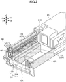
- FIG. 2 is a perspective view of the right rear extensible/contractible screed 31R.
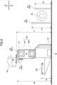
- FIG. 3 is a side view of the right rear extensible/contractible screed 31R as viewed from the -Y side (right side) of the right rear extensible/contractible screed 31R.
- FIG. 3 omits illustration of the right side plate 40R for the sake of clarification.
- the following description of the right rear extensible/contractible screed 31R also applies to the left rear extensible/contractible screed 31L.
- the right rear extensible/contractible screed 31R is primarily constituted with a shaft cover UF, guide shafts GS, a strike-off plate 33, and a screed plate 35. Further, as illustrated in FIG. 3 , the -Z side part (bottom part) of the right rear extensible/contractible screed 31R is primarily constituted with the strike-off plate 33 and the screed plate 35.
- the shaft cover UF is a member that constitutes the top end of the right rear extensible/contractible screed 31R.
- the shaft cover UF is formed to be virtually a rectangular parallelepiped, and configured to cover the top of the guide shafts GS.
- the guide shafts GS are configured to guide extension and contraction of the right rear extensible/contractible screed 31R.
- the guide shafts GS include an upper guide shaft GS1 and a lower guide shaft GS2.
- the strike-off plate 33 is a member to swallow (push) the paving material PV, that has been laid and spread by the screw SC and adjusted in quantity by the right extensible/contractible moldboard 43R, under the right rear extensible/contractible screed 31R.
- the strike-off plate 33 extends over the entire span of the right rear extensible/contractible screed 31R in the Y-axis direction (the vehicle-width direction), and has an inclined surface inclined with respect to the -Z side surface (bottom surface) of the screed plate 35 provided at the lower part.
- the inclined surface of the strike-off plate 33 and the bottom surface of the screed plate 35 form a swallowing angle of the paving material.
- the screed plate 35 is a member constituting the bottom part of the rear extensible/contractible screed 31 vibrated by a vibrator, to compact the paving material PV swallowed through a space between the roadbed RB and the strike-off plate 33.
- the screed plate 35 extends over the entire span of the rear extensible/contractible screed 31 in the vehicle-width direction.
- the operation box SB is a device used by the operator working behind the asphalt finisher 100 to operate the asphalt finisher 100.
- the operation box SB includes a lever switch, a push switch, a monitor, and the like (not illustrated), and is configured to allow the operator to adjust the state of extension and contraction of the leveling cylinders 23, the state of extension and contraction of the rear extensible/contractible screeds 31, and the spreading speed (operating speed) of the conveyor CV.
- the right front ribbon light E2R is arranged along the extension/contraction direction (Y-axis direction) at the front edge (the edge on the +X side) of the top surface of the shaft cover UF being virtually a rectangular parallelepiped constituting the right rear extensible/contractible screed 31R.
- the right front ribbon light E2R has a configuration in which 15 LEDs are separately arranged at predetermined equidistant intervals.
- the LEDs have the same size.
- the LEDs may be arranged separately at non-equidistant intervals, or may be arranged consecutively so that the LEDs are contiguous to one another in the extension/contraction direction.
- the LEDs may have different sizes.
- the right front ribbon light E2R may be constituted with a single elongated LED. The same applies to the left front ribbon light E2L.
- the right front ribbon light E2R may be configured to emit light in any luminescent color.
- the right front ribbon light E2R is configured to emit light in the same color as the right sidelight W3R.
- the right front ribbon light E2R may be configured to emit light in a luminescent color different from that of the right sidelight W3R. The same applies to the left front ribbon light E2L.
- the right front ribbon light E2R may be arranged on the front surface of the shaft cover UF (surface on the +X side), or may be arranged on the front edge of the lower surface of the shaft cover UF. Also, the right front ribbon light E2R may be arranged on another member constituting the right rear extensible/contractible screed 31R (desirably an elongated member extending in the extension/contraction direction). The same applies to the left front ribbon light E2L.
- the right front ribbon light E2R is desirably arranged at a relatively high position so as not to be hidden behind other members when viewed by the operator and the like from the front side (+X side).
- a height H1 of the right front ribbon light E2R from the ground is higher than a height H2 of the right retaining plate 42R from the ground, and higher than a height H3 of the right extensible/contractible moldboard 43R from the ground. The same applies to the left front ribbon light E2L.
- the right rear ribbon light E3R is arranged along the extension/contraction direction (Y-axis direction) at the rear edge (the edge on the -X side) of the top surface of the shaft cover UF of the right rear extensible/contractible screed 31R.
- the right rear ribbon light E3R has a configuration in which 15 LEDs are separately arranged at predetermined equidistant intervals.
- the LEDs have the same size.
- the LEDs may be arranged separately at non-equidistant intervals, or may be arranged consecutively so that the LEDs are contiguous to one another in the extension/contraction direction.
- the LEDs may have different sizes.
- the right rear ribbon light E3R may be constituted with a single elongated LED. The same applies to the left rear ribbon light E3L.
- the right rear ribbon light E3R may be configured to emit light in any luminescent color.
- the right rear ribbon light E3R is configured to emit light of the same color as the right backlight W4R.
- the right rear ribbon light E3R may be configured to emit light in a luminescent color different from that of the right backlight W4R. The same applies to the left rear ribbon light E3L.
- the right rear ribbon light E3R may be arranged on the rear surface of the shaft cover UF (surface on the -X side), or may be arranged on the rear edge of the lower surface of the shaft cover UF. Also, the right rear ribbon light E3R may be arranged on another member constituting the right rear extensible/contractible screed 31R (desirably an elongated member extending in the extension/contraction direction). The same applies to the left rear ribbon light E3L.
- the right rear ribbon light E3R is arranged at a relatively high position so as not to be hidden behind other members when viewed from the rear side (+X side).
- a height H4 of the right rear ribbon light E3R from the ground is higher than a height H5 of the right step 32R from the ground. The same applies to the left rear ribbon light E3L.
- both the right front ribbon light E2R and the right rear ribbon light E3R are attached to the right rear extensible/contractible screed 31R, so as not to hinder the right rear extensible/contractible screed 31R from being housed in a screed cover 3C. Therefore, in the present embodiment, the right front ribbon light E2R and the right rear ribbon light E3R are configured to be housed in the screed cover 3C together with the right rear extensible/contractible screed 31R. In other words, the attention lights E3 as the light emitting parts are configured to be housed in the screed cover 3C when the rear extensible/contractible screeds 31 are in a contracted state.
- the right front ribbon light E2R and the right rear ribbon light E3R may be configured to be easily attachable to and detachable from the right rear extensible/contractible screed 31R.
- the LEDs may be configured to be easily attachable and detachable.
- the right front ribbon light E2R and the right rear ribbon light E3R may be detached from the right rear extensible/contractible screed 31R when the right rear extensible/contractible screed 31R is to be housed in the screed cover 3C.
- the asphalt finisher 100 includes the tractor 1, the protruding parts protruding out of the width of the tractor 1, and the light emitting parts arranged consecutively or separately on the protruding parts.
- the protruding parts include, for example, the hopper 2, the rear extensible/contractible screeds 31, the extensible/contractible moldboards 43, and the like.
- the light emitting parts include, for example, the attention lights E1 to E3 and the like.
- the asphalt finisher 100 can improve the visibility of the parts protruding out of the width of the tractor 1. Therefore, a person viewing the asphalt finisher 100 from the outside can easily recognize the presence of the protruding parts, such as the hopper 2, the rear extensible/contractible screeds 31, the extensible/contractible moldboards 43, and the like even in the night. As a result, the asphalt finisher 100 can increase the safety of the work.
- the attention lights E2 and E3 as the light emitting parts are desirably arranged consecutively or separately along the extension/contraction direction of the rear extensible/contractible screeds 31.
- a person viewing the asphalt finisher 100 from the outside can easily recognize that the rear extensible/contractible screeds 31 extend continuously in the vehicle-width direction, namely, the rear extensible/contractible screeds 31 are connected to the main body of the asphalt finisher 100. Therefore, this configuration can prevent, for example, a person viewing the asphalt finisher 100 from the outside from erroneously recognizing that gaps (spaces) are present between the main body of the asphalt finisher 100 and the ends of the rear extensible/contractible screeds 31.
- the protruding parts may be the rear extensible/contractible screeds 31 that are extendable and contractible in the vehicle-width direction.
- the attention lights E2 and E3 as the light emitting parts may be arranged to illuminate spaces in front of and behind the rear extensible/contractible screeds 31.
- the asphalt finisher 100 can illuminate the spaces in front of and behind the rear extensible/contractible screeds 31 more brightly than in the case of illuminating only with the working lights W3 and W4.
- the operator working around the asphalt finisher 100 can easily confirm the amount of the paving material PV carried around the screw SC even in the night.
- the protruding parts may be the extensible/contractible moldboards 43 that are extendable and contractible in the vehicle-width direction.
- the light emitting parts may be arranged consecutively or separately on the extensible/contractible moldboards 43 along the extension/contraction direction of the extensible/contractible moldboards 43. With this configuration, the asphalt finisher 100 can improve the visibility of the extensible/contractible moldboards 43.
- the protruding parts may be the hopper 2 that can be opened and closed in the vehicle-width direction.
- the protruding parts may be the hopper wings 2W that can be opened and closed in the vehicle-width direction.
- the attention lights E1 as the light emitting parts may be arranged consecutively or separately along the end surfaces of the hopper wings 2W. With this configuration, the asphalt finisher 100 can improve the visibility of the hopper 2.
- the asphalt finisher 100 is typically provided with the working lights W1 to W4. Therefore, the attention lights E1 to E3 as the light emitting parts may be configured to be turned on when the working lights W1 to W4 are turned on. With this configuration, the operator can securely turn on the attention lights E1 to E3 when turning on the working lights W1 to W4. Therefore, the attention lights E1 to E3 can be prevented from being left turned off when night work starts.
- the light emitting parts include the attention lights E1 arranged along the end surfaces of the edges of the hopper wings 2W, the attention lights E2 arranged along the front edges of the top surfaces of the rear extensible/contractible screeds 31, and the attention lights E3 arranged along the rear edges of the top surfaces of the rear extensible/contractible screeds 31.
- the light emitting parts may include attention lights arranged at the front and the rear of the screed cover 3C.
- the light emitting parts may include an attention light arranged along the front edge of the top surface of the screed cover 3C, and an attention light arranged along the rear edge of the top surface of the screed cover 3C.
Landscapes
- Engineering & Computer Science (AREA)
- Mechanical Engineering (AREA)
- Architecture (AREA)
- Civil Engineering (AREA)
- Structural Engineering (AREA)
- Road Paving Machines (AREA)
Abstract
Description
- The present disclosure relates to an asphalt finisher.
- Conventionally, an asphalt finisher provided with lighting facilities has been known (see Patent Document 1). The lighting facilities are configured to illuminate work areas during night work.
- Patent Document 1: Japanese Laid-Open Patent Application No.
2004-116448 - However, the lighting facilities described above are not configured to illuminate parts protruding out of the width of a tractor, such as a bucket and a screed. Therefore, the parts protruding out of the width of the tractor may not be visible from the surroundings.
- Thereupon, it is desirable to provide an asphalt finisher that can improve the visibility of the parts protruding out of the width of the tractor.
- An asphalt finisher according to an embodiment of the present invention includes a tractor; a protruding part protruding out of a width of the tractor; and a light emitting part arranged consecutively or separately on the protruding part.
- By the means described above, an asphalt finisher that can improve the visibility of the parts protruding out of the width of the tractor is provided.
-
-
FIG. 1A is a side view of an asphalt finisher; -
FIG. 1B is a top view of the asphalt finisher; -
FIG. 1C is a top view of the asphalt finisher; -
FIG. 2 is a perspective view of a right rear extensible/contractible screed; and -
FIG. 3 is a side view of the right rear extensible/contractible screed. -
FIGs. 1A to 1C illustrate an example of anasphalt finisher 100 as an example of a road machine according to an embodiment of the present invention. Specifically,FIG. 1A is a side view of theasphalt finisher 100, andFIGs. 1B and1C are top views of theasphalt finisher 100. The coarsest dot patterns AP inFIG. 1B indicate surfaces of existing pavement or the like, and a cross pattern NP indicates a new pavement. - The
asphalt finisher 100 is primarily constituted with atractor 1, ahopper 2, and a screed 3. In the following, the direction of thehopper 2 viewed from the tractor 1 (+X direction) is assumed to be the front, and the direction of the screed 3 viewed from the tractor 1 (-X direction) is assumed to be the rear. - The
tractor 1 is a mechanism for causing theasphalt finisher 100 to travel. In the present embodiment, thetractor 1 rotatesrear wheels 5 by using rear-wheel traction motors, and rotatesfront wheels 6 by using front-wheel traction motors, to move theasphalt finisher 100. The rear-wheel traction motors and the front-wheel traction motors receive supply of hydraulic oil from the hydraulic pump, to rotate. Therear wheels 5 and thefront wheels 6 may be replaced with crawlers. - A
controller 50 is a control device to control theasphalt finisher 100. In the present embodiment, thecontroller 50 is constituted with an arithmetic/logic processing device including a CPU, a volatile storage device, and a non-volatile storage device, and installed in thetractor 1. Various functions of thecontroller 50 are implemented by the CPU executing programs stored in the non-volatile storage device. - The
hopper 2 is a mechanism for receiving paving materials. In the present embodiment, thehopper 2 is arranged in front of thetractor 1, and includeshopper wings 2W. Thehopper wings 2W are configured to be capable of being opened and closed in the Y-axis direction (the vehicle-width direction) byhopper cylinders 24. - Specifically, the
hopper wings 2W include a left hopper wing 2WL and a right hopper wing 2WR, and thehopper cylinders 24 include aleft hopper cylinder 24L and aright hopper cylinder 24R. Further, the left hopper wing 2WL is configured to be capable of being opened and closed by theleft hopper cylinder 24L in the Y-axis direction (the vehicle-width direction), and the right hopper wing 2WR is configured to be capable of being opened and closed by theright hopper cylinder 24R in the Y-axis direction (the vehicle-width direction). When thehopper wings 2W open, thehopper wings 2W protrude out of the width of the tractor 1 (the length in the Y-axis direction); therefore, the width of the asphalt finisher 100 (the length in the Y-axis direction) becomes greater. - The
asphalt finisher 100 normally receives a paving material (e.g., an asphalt mixture) from the bed of a dump truck with thehopper wings 2W in a fully opened state.FIGs. 1A to 1C illustrate thehopper wings 2W in a fully opened state. When the paving material in thehopper 2 decreases, thehopper wings 2W are closed, and the paving material remaining near the inner walls of thehopper wings 2W is collected to be gathered at the center of thehopper 2. This is to allow a conveyor CV at the center of thehopper 2 to feed the paving material behind thetractor 1. The paving material fed behind thetractor 1 is laid and spread by a screw SC in the vehicle-width direction behind thetractor 1 and in front of thescreed 3. In the present embodiment, the screw SC is in a state where extension screws are connected on the left and on the right. - The
screed 3 is a mechanism for laying and leveling the pavement material. In the present embodiment, thescreed 3 primarily includesfront screeds 30 and rear extensible/contractible screeds 31. Thescreed 3 is a floating screed towed by thetractor 1 and coupled with thetractor 1 via levelingarms 3A. Thescreed 3 is moved up and down together with the levelingarms 3A by extension and contraction of screedlift cylinders 25. - The
front screeds 30 include a left front screed 30L and a right front screed 30R, and the rear extensible/contractible screeds 31 include a left rear extensible/contractible screed 31L and a right rear extensible/contractible screed 31R. The left rear extensible/contractible screed 31L is extended or contracted in the vehicle-width direction by using a screedextension cylinder 26L, and the right rear extensible/contractible screed 31R is extended or contracted in the vehicle-width direction by using a screedextension cylinder 26R. When the rear extensible/contractible screeds 31 extend, the width of the asphalt finisher 100 (the length in the Y-axis direction) becomes greater because the rear extensible/contractible screeds 31 protrude out of the width of thetractor 1. - In order to compact the pavement, the left front screed 30L is vibrated by a left
front vibrator 27L, and the right front screed 30R is vibrated by a rightfront vibrator 27R. Similarly, the left rear extensible/contractible screed 31L is vibrated by a left rear vibrator 28L, and the right rear extensible/contractible screed 31R is vibrated by a right rear vibrator 28R. - Leveling
cylinders 23 are hydraulic cylinders that move the front end parts of the levelingarms 3A up and down to spread and level the asphalt mixture so as to adjust the thickness. -
Side plates 40 are attached to the ends of thescreed 3. Theside plates 40 limit excessive spread of the paving material PV laid and spread by the screw SC in the vehicle-width direction.FIGs. 1A and1B illustrate the paving material PV to be laid and spread by the screw SC with fine dot patterns. Theside plates 40 include aright side plate 40R extending forward from the right rear extensible/contractible screed 31R, and aleft side plate 40L extending from the left rear extensible/contractible screed 31L. - Retaining
plates 42 are attached to the sides of thetractor 1. The retainingplates 42 prevent the paving material PV from spattering forward in the vicinity of the tractor 1 (particularly the rear wheels 5) due to rotation of the screw SC. In the present embodiment, the retainingplates 42 include aright retaining plate 42R attached to the right side surface of thetractor 1, and aleft retaining plate 42L attached to the left side surface of thetractor 1. Theleft retaining plate 42L is attached to the left side surface of thetractor 1, to be rotatable (collapsible). The same applies to theright retaining plate 42R. - Extensible/
contractible moldboards 43 are attached to the front of thescreed 3. The extensible/contractible moldboards 43 constitute a mechanism for adjusting the amount of the paving material PV remaining in front of thescreed 3. In the present embodiment, the extensible/contractible moldboards 43 are configured to be extensible and contractible by hydraulic actuators (not illustrated) in accordance with extension and contraction of the rear extensible/contractible screeds 31. The paving material PV passes through gaps between the lower ends of the extensible/contractible moldboards 43 and a roadbed RB, to reach a space beneath thescreed 3. In the present embodiment, the extensible/contractible moldboards 43 include a right extensible/contractible moldboard 43R attached in front of the right rear extensible/contractible screed 31R, and a left extensible/contractible moldboard 43L attached in front of the left rear extensible/contractible screed 31L. The left extensible/contractible moldboard 43L is configured to be adjustable in height in the Z-axis direction, irrespective of theleft side plate 40L and the left rear extensible/contractible screed 31L. This is to adjust the amount of paving material remaining in front of the left rear extensible/contractible screed 31L, by moving the left extensible/contractible moldboard 43L up and down. The same applies to the right extensible/contractible moldboard 43R. -
Steps 32 are attached to the rear of thescreed 3. Thesteps 32 are footholds that can be used by the operator. In the present embodiment, thesteps 32 include a central step 32C attached to the rear of thefront screed 30, aright step 32R attached to the rear of the right rear extensible/contractible screed 31R, and aleft step 32L attached to the rear of the left rear extensible/contractible screed 31L. - The
asphalt finisher 100 is provided with working lights W1 to W4. In the present embodiment, the working lights W1 to W4 illuminate predetermined spaces by typically using power generated by a generator 12 (an alternator) installed in thetractor 1. Thegenerator 12 is driven by anengine 11 as the drive source installed in thetractor 1. However, the working lights W1 to W4 may illuminate predetermined spaces by using power of astorage battery 13 as a battery installed in thetractor 1. - In the present embodiment, the working lights W1 to W4 are LED lamps. However, the working lights W1 to W4 may be HID lamps, halogen lamps, or the like. The working lights W1 to W4 are configured to be switched between turned-on and turned-off states typically by a switch SW. As illustrated in
FIG. 1A , the switch SW is typically included in an operation panel arranged in front of the driver's seat. However, the switch SW may be arranged in another part of theasphalt finisher 100, such as in an operation box SB (seeFIG. 2 ) arranged on thescreed 3. The working lights W1 to W4 may be configured be switched between turned-on and turned-off states by a single switch SW, or may be configured be switched between turned-on and turned-off states by separate switches SW. - The working lights W1 are headlights illuminating a space in front of (in the traveling direction of) the
asphalt finisher 100. As illustrated inFIG. 1B , the working lights W1 include a left headlight W1L arranged at the left end of the front end of thetractor 1, and a right headlight W1R arranged at the right end of the front end of thetractor 1. - The working light W2 illuminates the interior of the
hopper 2. As illustrated inFIG. 1B , the working light W2 is arranged at the center of the front end of thetractor 1, to illuminate an area R1 inside thehopper 2 designated by a coarse dot pattern inFIG. 1C . - The working lights W3 illuminate spaces in front of the rear extensible/
contractible screeds 31. As illustrated inFIGs. 1A and1B , the working lights W3 are arranged on the sidewalls of thetractor 1. Specifically, the working lights W3 include a left sidelight W3L and a right sidelight W3R. The left sidelight W3L illuminates an area R2 in front of the left rear extensible/contractible screed 31L designated by a coarse dot pattern inFIG. 1C . The right sidelight W3R illuminates an area R3 in front of the right rear extensible/contractible screed 31R designated by a coarse dot pattern inFIG. 1C . - The working lights W4 illuminate spaces behind the rear extensible/
contractible screeds 31. As illustrated inFIGs. 1A and1B , the working lights W4 are arranged at the rear end of a canopy CP. Specifically, the working lights W4 include a left backlight W4L and a right backlight W4R. The left backlight W4L illuminates an area R4 on the left and behind the left rear extensible/contractible screed 31L designated by a coarse dot pattern inFIG. 1C . The right backlight W4R illuminates an area R5 on the right and behind the right rear extensible/contractible screed 31R designated by a coarse dot pattern inFIG. 1C . - The
asphalt finisher 100 is provided with light emitting parts that are arranged consecutively or separately at protruding parts that protrude out of the width of thetractor 1. In the present embodiment, the protruding parts include thehopper 2, the rear extensible/contractible screeds 31, the extensible/contractible moldboards 43, and the like. The light emitting parts include attention lights E1 to E3. - In the present embodiment, the attention lights E1 to E3 emit light by typically using power generated by the generator 12 (an alternator), similar to the working lights W1 to W4. However, the attention lights E1 to E3 may emit light by using power of the
battery 13 installed in thetractor 1. - The attention lights E1 to E3 are LED ribbon lights in the present embodiment. However, the attention lights E1 to E3 may be filament lamps, xenon lamps, or the like. The attention lights E1 to E3 are configured to be typically turned on when the working lights W1 to W4 are turned on. In the present embodiment, the attention lights E1 to E3 are configured to be turned on when the working lights W1 to W4 are turned on by the switch SW, and to be turned off when the working lights W1 to W4 are turned off by the switch SW. However, the attention lights E1 to E3 may be switched between on and off irrespective of the working lights W1 to W4. For example, the attention lights E1 to E3 may be configured to be automatically turned on when the surroundings are determined to become dark based on the output of an irradiation sensor (not illustrated).
- Each of the attention lights E1 to E3 may be configured to emit light in any lighting/blinking mode such as continuous lighting, simultaneous blinking, sequential blinking, or the like. Continuous lighting designates a lighting mode, for example, in which all of the multiple LEDs constituting the attention lights E2 are lit continuously. Simultaneous blinking designates a blinking mode, for example, in which each of the multiple LEDs constituting the attention lights E2 blinks at the same timing. Sequential blinking designates a blinking mode in which each of the multiple LEDs constituting the attention lights E2 blinks at a timing different from one another and in a predetermined order. A lighting/blinking mode may be configured to vary depending on the state of protrusion, the protrusion speed, or the like of the protruding parts. The protrusion speed includes, for example, the opening/closing speed of the
hopper 2, the extension and contraction speed of the rear extensible/contractible screeds 31, the extension and contraction speed of the extensible/contractible moldboards 43, and the like. - The attention lights E1 are light emitting parts that increase the visibility of the
hopper wings 2W as the protruding parts. As illustrated inFIG. 1B , the attention lights E1 include a left ribbon light E1L arranged along the end surface at the edge of the left hopper wing 2WL, and a right ribbon light E1R arranged along the end surface at the edge of the right hopper wing 2WR. The left ribbon light E1L is connected to thecontroller 50 via a signal line S1L, and the right ribbon light E1R is connected to thecontroller 50 via a signal line S1R. Note that the attention lights E1 may be arranged at portions of thehopper wings 2W close to the edges of the outer walls. - With this configuration, the driver of a dump truck supplying the paving material to the
hopper 2 can easily recognize an opening/closing state of thehopper wings 2W when moving backward toward theasphalt finisher 100 during night work. Also, the driver of a vehicle driving on an existing road adjacent to the road under construction can easily recognize an opening/closing state of thehopper wings 2W, when approaching theasphalt finisher 100 from the front side (+X side) while driving in the night. - The attention lights E2 are light emitting parts that increase the visibility from the front side of the rear extensible/
contractible screeds 31 as the protruding parts. As illustrated inFIG. 1B , the attention lights E2 include a left front ribbon light E2L arranged along the front edge of the top surface of the left rear extensible/contractible screed 31L, and a right front ribbon light E2R arranged along the front edge of the top surface of the right rear extensible/contractible screed 31R. The left front ribbon light E2L is connected to thecontroller 50 via a signal line S2L, and the right front ribbon light E2R is connected to thecontroller 50 via a signal line S2R. - The left front ribbon light E2L illuminates an area R2A in front of the left rear extensible/
contractible screed 31L designated by a fine dot pattern inFIG. 1C . The area R2A is part of the area R2. The right front ribbon light E2R illuminates an area R3A in front of the right rear extensible/contractible screed 31R designated by a fine dot pattern inFIG. 1C . The area R3A is part of the area R3. - With this configuration, the driver of a vehicle driving on an existing road adjacent to the road under construction can easily recognize the state of extension and contraction of the rear extensible/
contractible screeds 31, when approaching theasphalt finisher 100 from the front side (+X side) while driving in the night. Also, the attention lights E2 may also function as auxiliary lights to assist illumination by the working lights W3. - The attention lights E3 are light emitting parts that increase the visibility from behind the rear extensible/
contractible screeds 31 as the protruding parts. As illustrated inFIG. 1B , the attention lights E3 include a left rear ribbon light E3L arranged along the rear edge of the top surface of the left rear extensible/contractible screed 31L, and a right rear ribbon light E3R arranged along the rear edge of the top surface of the right rear extensible/contractible screed 31R. The left rear ribbon light E3L is connected to thecontroller 50 via a signal line S3L, and the right rear ribbon light E3R is connected to thecontroller 50 via a signal line S3R. - The left rear ribbon light E3L illuminates an area R4A behind the left rear extensible/
contractible screed 31L designated by a fine dot pattern inFIG. 1C . The area R4A is part of the area R4. The right rear ribbon light E3R illuminates an area R5A behind the right rear extensible/contractible screed 31R designated by a fine dot pattern inFIG. 1C . The area R5A is part of the area R5. - With this configuration, the driver of a vehicle driving on an existing road adjacent to the road under construction can easily recognize the state of extension and contraction of the rear extensible/
contractible screeds 31, when approaching theasphalt finisher 100 from behind (-X side) while driving in the night. Also, the attention lights E3 may also function as auxiliary lights to assist illumination by the working lights W4. - Next, with reference to
FIGs. 2 and3 , the rear extensible/contractible screeds 31 will be described.FIG. 2 is a perspective view of the right rear extensible/contractible screed 31R.FIG. 3 is a side view of the right rear extensible/contractible screed 31R as viewed from the -Y side (right side) of the right rear extensible/contractible screed 31R. However,FIG. 3 omits illustration of theright side plate 40R for the sake of clarification. The following description of the right rear extensible/contractible screed 31R also applies to the left rear extensible/contractible screed 31L. - As illustrated in
FIGs. 2 and3 , the right rear extensible/contractible screed 31R is primarily constituted with a shaft cover UF, guide shafts GS, a strike-off plate 33, and ascreed plate 35. Further, as illustrated inFIG. 3 , the -Z side part (bottom part) of the right rear extensible/contractible screed 31R is primarily constituted with the strike-off plate 33 and thescreed plate 35. - The shaft cover UF is a member that constitutes the top end of the right rear extensible/
contractible screed 31R. In the present embodiment, the shaft cover UF is formed to be virtually a rectangular parallelepiped, and configured to cover the top of the guide shafts GS. - The guide shafts GS are configured to guide extension and contraction of the right rear extensible/
contractible screed 31R. In the present embodiment, the guide shafts GS include an upper guide shaft GS1 and a lower guide shaft GS2. - The strike-
off plate 33 is a member to swallow (push) the paving material PV, that has been laid and spread by the screw SC and adjusted in quantity by the right extensible/contractible moldboard 43R, under the right rear extensible/contractible screed 31R. In the present embodiment, the strike-off plate 33 extends over the entire span of the right rear extensible/contractible screed 31R in the Y-axis direction (the vehicle-width direction), and has an inclined surface inclined with respect to the -Z side surface (bottom surface) of thescreed plate 35 provided at the lower part. The inclined surface of the strike-off plate 33 and the bottom surface of thescreed plate 35 form a swallowing angle of the paving material. - The
screed plate 35 is a member constituting the bottom part of the rear extensible/contractible screed 31 vibrated by a vibrator, to compact the paving material PV swallowed through a space between the roadbed RB and the strike-off plate 33. In the present embodiment, thescreed plate 35 extends over the entire span of the rear extensible/contractible screed 31 in the vehicle-width direction. - The operation box SB is a device used by the operator working behind the
asphalt finisher 100 to operate theasphalt finisher 100. In the present embodiment, the operation box SB includes a lever switch, a push switch, a monitor, and the like (not illustrated), and is configured to allow the operator to adjust the state of extension and contraction of the levelingcylinders 23, the state of extension and contraction of the rear extensible/contractible screeds 31, and the spreading speed (operating speed) of the conveyor CV. - The right front ribbon light E2R is arranged along the extension/contraction direction (Y-axis direction) at the front edge (the edge on the +X side) of the top surface of the shaft cover UF being virtually a rectangular parallelepiped constituting the right rear extensible/
contractible screed 31R. Specifically, the right front ribbon light E2R has a configuration in which 15 LEDs are separately arranged at predetermined equidistant intervals. The LEDs have the same size. However, the LEDs may be arranged separately at non-equidistant intervals, or may be arranged consecutively so that the LEDs are contiguous to one another in the extension/contraction direction. Also, the LEDs may have different sizes. Also, the right front ribbon light E2R may be constituted with a single elongated LED. The same applies to the left front ribbon light E2L. - The right front ribbon light E2R may be configured to emit light in any luminescent color. In the present embodiment, the right front ribbon light E2R is configured to emit light in the same color as the right sidelight W3R. However, the right front ribbon light E2R may be configured to emit light in a luminescent color different from that of the right sidelight W3R. The same applies to the left front ribbon light E2L.
- The right front ribbon light E2R may be arranged on the front surface of the shaft cover UF (surface on the +X side), or may be arranged on the front edge of the lower surface of the shaft cover UF. Also, the right front ribbon light E2R may be arranged on another member constituting the right rear extensible/
contractible screed 31R (desirably an elongated member extending in the extension/contraction direction). The same applies to the left front ribbon light E2L. - The right front ribbon light E2R is desirably arranged at a relatively high position so as not to be hidden behind other members when viewed by the operator and the like from the front side (+X side). In the present embodiment, as illustrated in
FIG. 3 , a height H1 of the right front ribbon light E2R from the ground is higher than a height H2 of theright retaining plate 42R from the ground, and higher than a height H3 of the right extensible/contractible moldboard 43R from the ground. The same applies to the left front ribbon light E2L. - The right rear ribbon light E3R is arranged along the extension/contraction direction (Y-axis direction) at the rear edge (the edge on the -X side) of the top surface of the shaft cover UF of the right rear extensible/
contractible screed 31R. Specifically, as in the case of the right front ribbon light E2R, the right rear ribbon light E3R has a configuration in which 15 LEDs are separately arranged at predetermined equidistant intervals. The LEDs have the same size. However, the LEDs may be arranged separately at non-equidistant intervals, or may be arranged consecutively so that the LEDs are contiguous to one another in the extension/contraction direction. Also, the LEDs may have different sizes. Also, the right rear ribbon light E3R may be constituted with a single elongated LED. The same applies to the left rear ribbon light E3L. - The right rear ribbon light E3R may be configured to emit light in any luminescent color. In the present embodiment, the right rear ribbon light E3R is configured to emit light of the same color as the right backlight W4R. However, the right rear ribbon light E3R may be configured to emit light in a luminescent color different from that of the right backlight W4R. The same applies to the left rear ribbon light E3L.
- The right rear ribbon light E3R may be arranged on the rear surface of the shaft cover UF (surface on the -X side), or may be arranged on the rear edge of the lower surface of the shaft cover UF. Also, the right rear ribbon light E3R may be arranged on another member constituting the right rear extensible/
contractible screed 31R (desirably an elongated member extending in the extension/contraction direction). The same applies to the left rear ribbon light E3L. - The right rear ribbon light E3R is arranged at a relatively high position so as not to be hidden behind other members when viewed from the rear side (+X side). In the present embodiment, as illustrated in
FIG. 3 , a height H4 of the right rear ribbon light E3R from the ground is higher than a height H5 of theright step 32R from the ground. The same applies to the left rear ribbon light E3L. - Both the right front ribbon light E2R and the right rear ribbon light E3R are attached to the right rear extensible/
contractible screed 31R, so as not to hinder the right rear extensible/contractible screed 31R from being housed in ascreed cover 3C. Therefore, in the present embodiment, the right front ribbon light E2R and the right rear ribbon light E3R are configured to be housed in thescreed cover 3C together with the right rear extensible/contractible screed 31R. In other words, the attention lights E3 as the light emitting parts are configured to be housed in thescreed cover 3C when the rear extensible/contractible screeds 31 are in a contracted state. However, the right front ribbon light E2R and the right rear ribbon light E3R may be configured to be easily attachable to and detachable from the right rear extensible/contractible screed 31R. For example, the LEDs may be configured to be easily attachable and detachable. In this case, the right front ribbon light E2R and the right rear ribbon light E3R may be detached from the right rear extensible/contractible screed 31R when the right rear extensible/contractible screed 31R is to be housed in thescreed cover 3C. The same applies to the left front ribbon light E2L and the left rear ribbon light E3L. - As described above, the
asphalt finisher 100 includes thetractor 1, the protruding parts protruding out of the width of thetractor 1, and the light emitting parts arranged consecutively or separately on the protruding parts. The protruding parts include, for example, thehopper 2, the rear extensible/contractible screeds 31, the extensible/contractible moldboards 43, and the like. The light emitting parts include, for example, the attention lights E1 to E3 and the like. - With this configuration, the
asphalt finisher 100 can improve the visibility of the parts protruding out of the width of thetractor 1. Therefore, a person viewing theasphalt finisher 100 from the outside can easily recognize the presence of the protruding parts, such as thehopper 2, the rear extensible/contractible screeds 31, the extensible/contractible moldboards 43, and the like even in the night. As a result, theasphalt finisher 100 can increase the safety of the work. - The attention lights E2 and E3 as the light emitting parts are desirably arranged consecutively or separately along the extension/contraction direction of the rear extensible/
contractible screeds 31. With this configuration, a person viewing theasphalt finisher 100 from the outside can easily recognize that the rear extensible/contractible screeds 31 extend continuously in the vehicle-width direction, namely, the rear extensible/contractible screeds 31 are connected to the main body of theasphalt finisher 100. Therefore, this configuration can prevent, for example, a person viewing theasphalt finisher 100 from the outside from erroneously recognizing that gaps (spaces) are present between the main body of theasphalt finisher 100 and the ends of the rear extensible/contractible screeds 31. - The protruding parts may be the rear extensible/
contractible screeds 31 that are extendable and contractible in the vehicle-width direction. In this case, the attention lights E2 and E3 as the light emitting parts may be arranged to illuminate spaces in front of and behind the rear extensible/contractible screeds 31. With this configuration, theasphalt finisher 100 can illuminate the spaces in front of and behind the rear extensible/contractible screeds 31 more brightly than in the case of illuminating only with the working lights W3 and W4. As a result, for example, the operator working around theasphalt finisher 100 can easily confirm the amount of the paving material PV carried around the screw SC even in the night. - The protruding parts may be the extensible/
contractible moldboards 43 that are extendable and contractible in the vehicle-width direction. In this case, the light emitting parts may be arranged consecutively or separately on the extensible/contractible moldboards 43 along the extension/contraction direction of the extensible/contractible moldboards 43. With this configuration, theasphalt finisher 100 can improve the visibility of the extensible/contractible moldboards 43. - The protruding parts may be the
hopper 2 that can be opened and closed in the vehicle-width direction. Specifically, the protruding parts may be thehopper wings 2W that can be opened and closed in the vehicle-width direction. In this case, the attention lights E1 as the light emitting parts may be arranged consecutively or separately along the end surfaces of thehopper wings 2W. With this configuration, theasphalt finisher 100 can improve the visibility of thehopper 2. - The
asphalt finisher 100 is typically provided with the working lights W1 to W4. Therefore, the attention lights E1 to E3 as the light emitting parts may be configured to be turned on when the working lights W1 to W4 are turned on. With this configuration, the operator can securely turn on the attention lights E1 to E3 when turning on the working lights W1 to W4. Therefore, the attention lights E1 to E3 can be prevented from being left turned off when night work starts. - As described above, favorable embodiments according to the present invention have been described. However, the present invention is not limited to the embodiments described above. Various modifications, substitutions, and the like may be applied to the embodiments described above without deviating from the scope of the present invention. Also, each of the features described with reference to the embodiments described above may be combined with the other appropriately, unless no technical conflict is introduced.
- For example, in the embodiments described above, the light emitting parts include the attention lights E1 arranged along the end surfaces of the edges of the
hopper wings 2W, the attention lights E2 arranged along the front edges of the top surfaces of the rear extensible/contractible screeds 31, and the attention lights E3 arranged along the rear edges of the top surfaces of the rear extensible/contractible screeds 31. However, the light emitting parts may include attention lights arranged at the front and the rear of thescreed cover 3C. For example, the light emitting parts may include an attention light arranged along the front edge of the top surface of thescreed cover 3C, and an attention light arranged along the rear edge of the top surface of thescreed cover 3C. - This application claims priority based on Japanese Patent Application No.
2018-146897, filed on August 3, 2018 -
- 1 tractor
- 2 hopper
- 2W hopper wing
- 2WL left hopper wing
- 2WR right hopper wing
- 3 screed
- 3a leveling arm
- 5 rear wheel
- 6 front wheel
- 11 engine
- 12 generator
- 13 storage battery
- 23 leveling cylinder
- 24 hopper cylinder
- 25 screed lift cylinder
- 26L, 26R screed extension/contraction cylinder
- 27L left front vibrator
- 27R right front vibrator
- 28L left rear vibrator
- 28R right rear vibrator
- 30 front screed
- 31 rear extensible/contractible screed
- 32 step
- 33 strike-off plate
- 35 screed plate
- 40 side plate
- 42 retaining plate
- 43 extensible/contractible moldboard
- 50 controller
- 100 asphalt finisher
- CP canopy
- CV conveyor
- E1 to E3 attention light
- PV paving material
- RB roadbed
- S1L, S1R, S2L, S2R, S3L, S3R signal line
- SC screw
- SW switch
- UF shaft cover
- W1 to W4 working light
Claims (9)
- An asphalt finisher comprising:a tractor;a protruding part protruding out of a width of the tractor; anda light emitting part arranged consecutively or separately on the protruding part.
- The asphalt finisher as claimed in claim 1, wherein the protruding part is an extension/contraction screed that is extendable and contractible in a vehicle-width direction, and
wherein the light emitting part is arranged consecutively or separately along an extension/contraction direction of the extension/contraction screed. - The asphalt finisher as claimed in claim 2, wherein the light emitting part is arranged to illuminate a space in front of and a space behind the extension/contraction screed.
- The asphalt finisher as claimed in claim 1, wherein the protruding part is an extensible/contractible moldboard that is extendable and contractible in a vehicle-width direction, and
wherein the light emitting part is consecutively or separately arranged on the extensible/contractible moldboard along an extension/contraction direction of the extensible/contractible moldboard. - The asphalt finisher as claimed in claim 1, wherein the protruding part is a hopper that can be opened and closed in a vehicle-width direction, and
wherein the light emitting part is arranged consecutively or separately along an end surface of the hopper. - The asphalt finisher as claimed in claim 1, further comprising: a working light,
wherein the light emitting part is configured to be turned on when the working light is turned on. - The asphalt finisher as claimed in claim 2, wherein, the light emitting part is configured to be housed in a screed cover while the extension/contraction screed is in a contracted state.
- The asphalt finisher as claimed in claim 7, wherein the light emitting part is arranged at a front of and a rear of the screed cover.
- The asphalt finisher as claimed in claim 1, wherein the light emitting part is configured to blink.
Applications Claiming Priority (2)
| Application Number | Priority Date | Filing Date | Title |
|---|---|---|---|
| JP2018146897 | 2018-08-03 | ||
| PCT/JP2019/030410 WO2020027313A1 (en) | 2018-08-03 | 2019-08-02 | Asphalt finisher |
Publications (3)
| Publication Number | Publication Date |
|---|---|
| EP3832018A1 true EP3832018A1 (en) | 2021-06-09 |
| EP3832018A4 EP3832018A4 (en) | 2021-09-15 |
| EP3832018B1 EP3832018B1 (en) | 2024-12-18 |
Family
ID=69231861
Family Applications (1)
| Application Number | Title | Priority Date | Filing Date |
|---|---|---|---|
| EP19844096.8A Active EP3832018B1 (en) | 2018-08-03 | 2019-08-02 | Asphalt finisher |
Country Status (4)
| Country | Link |
|---|---|
| EP (1) | EP3832018B1 (en) |
| JP (1) | JP7585787B2 (en) |
| CN (1) | CN112368446A (en) |
| WO (1) | WO2020027313A1 (en) |
Families Citing this family (2)
| Publication number | Priority date | Publication date | Assignee | Title |
|---|---|---|---|---|
| EP3868957B1 (en) * | 2020-02-20 | 2023-08-02 | Joseph Vögele AG | Road finisher with indirect lighting of a working area |
| JP2024021360A (en) * | 2022-08-03 | 2024-02-16 | 日本道路株式会社 | Road construction display device and road construction location display method |
Family Cites Families (20)
| Publication number | Priority date | Publication date | Assignee | Title |
|---|---|---|---|---|
| JPH0743133Y2 (en) * | 1991-04-17 | 1995-10-04 | 株式会社新潟鉄工所 | Dump truck guidance device in asphalt finisher |
| US5352063A (en) * | 1992-09-30 | 1994-10-04 | Allen Engineering Corporation | Polymer concrete paving machine |
| JPH0660608U (en) * | 1993-02-03 | 1994-08-23 | 範多機械株式会社 | Asphalt finisher hopper |
| JP2505210Y2 (en) * | 1993-04-09 | 1996-07-24 | 建設省東北地方建設局長 | Automatic steering device for paving vehicles |
| JPH074166U (en) * | 1993-06-17 | 1995-01-20 | 株式会社アイチコーポレーション | Work display device for work vehicles |
| JP2001138803A (en) * | 1999-11-12 | 2001-05-22 | Shin Caterpillar Mitsubishi Ltd | Side marker lamp mounting structure of working device |
| JP2002160575A (en) * | 2000-11-28 | 2002-06-04 | Shinmeiwa Auto Engineering Ltd | Alarm device for working vehicle |
| JP2004116448A (en) | 2002-09-27 | 2004-04-15 | Shin Caterpillar Mitsubishi Ltd | Engine control device for asphalt finisher |
| JP2004143894A (en) * | 2002-10-21 | 2004-05-20 | Seki Kogyo Kk | Car width display lamp of snow removing blade |
| JP2006062545A (en) * | 2004-08-27 | 2006-03-09 | Souji Kobayashi | Collision accident prevention device when opening door of automobile |
| JP4450387B2 (en) * | 2005-04-12 | 2010-04-14 | キャタピラージャパン株式会社 | Mounting structure for lighting equipment in construction machinery. |
| JP5637933B2 (en) * | 2011-05-20 | 2014-12-10 | 住友建機株式会社 | Screed device expansion / contraction mold board vertical adjustment mechanism |
| EP2578748B1 (en) * | 2011-10-04 | 2018-08-29 | Joseph Vögele AG | External control panel for a construction machine |
| DE102015008315A1 (en) * | 2015-06-30 | 2017-01-05 | Dynapac Gmbh | Screed and paver |
| PL3214223T3 (en) * | 2016-03-04 | 2019-11-29 | Joseph Voegele Ag | Road finisher with lateral operating unit |
| CN205951811U (en) * | 2016-08-19 | 2017-02-15 | 南京快联路桥建设工程有限公司 | Paver illumination structure |
| JP2018146897A (en) | 2017-03-08 | 2018-09-20 | 株式会社リコー | Power supply device and image forming apparatus |
| CN206800131U (en) * | 2017-06-08 | 2017-12-26 | 路敏 | Heat-regenerating paver of asphalt pavement |
| JP2019002205A (en) * | 2017-06-15 | 2019-01-10 | 範多機械株式会社 | Asphalt finisher |
| CN207619871U (en) * | 2017-12-12 | 2018-07-17 | 漆亮 | A kind of solar building construction alarming device |
-
2019
- 2019-08-02 CN CN201980044327.XA patent/CN112368446A/en active Pending
- 2019-08-02 EP EP19844096.8A patent/EP3832018B1/en active Active
- 2019-08-02 WO PCT/JP2019/030410 patent/WO2020027313A1/en not_active Ceased
- 2019-08-02 JP JP2020534765A patent/JP7585787B2/en active Active
Also Published As
| Publication number | Publication date |
|---|---|
| JPWO2020027313A1 (en) | 2021-08-10 |
| CN112368446A (en) | 2021-02-12 |
| EP3832018A4 (en) | 2021-09-15 |
| JP7585787B2 (en) | 2024-11-19 |
| WO2020027313A1 (en) | 2020-02-06 |
| EP3832018B1 (en) | 2024-12-18 |
Similar Documents
| Publication | Publication Date | Title |
|---|---|---|
| EP3832018B1 (en) | Asphalt finisher | |
| CN103031800B (en) | External control stand for a construction machine | |
| EP3237253B1 (en) | Material transfer vehicle having an expandable truck-receiving hopper | |
| EP0957204A1 (en) | Roadpaver and hopper | |
| DE112015000723T5 (en) | Headlight control device | |
| US11178738B2 (en) | Working machine | |
| US5531542A (en) | Dual auger/conveyor drive for a paver | |
| JP7844790B2 (en) | Road machinery | |
| JP4246849B2 (en) | Paving machine | |
| CN111827053A (en) | Compactor cylinder edge indicating device | |
| JP2018044281A (en) | Safety monitoring device for road surface cutting vehicles | |
| JP2025128272A (en) | Construction machinery equipped with lighting equipment | |
| US3330188A (en) | Road widener | |
| RU2465393C1 (en) | Snow removal blade | |
| ITVI950052A1 (en) | IMPROVED SCARING MACHINE FOR THE REMOVAL OF ROAD SURFACES | |
| KR101911921B1 (en) | Median strip having function of traffic signal | |
| JP2024021360A (en) | Road construction display device and road construction location display method | |
| WO2023190355A1 (en) | Road machine | |
| RU129512U1 (en) | SELF-PROPELLED ROAD-BUILDING UNIT | |
| RU2541966C2 (en) | Self-propelled road-building machine | |
| JPH0634404Y2 (en) | Asphalt finisher | |
| JP2508465Y2 (en) | Asphalt finisher bar conveyor | |
| JP6571722B2 (en) | Working machine | |
| CN120211165A (en) | Road Machinery | |
| JP2000054311A (en) | Asphalt finisher |
Legal Events
| Date | Code | Title | Description |
|---|---|---|---|
| STAA | Information on the status of an ep patent application or granted ep patent |
Free format text: STATUS: THE INTERNATIONAL PUBLICATION HAS BEEN MADE |
|
| PUAI | Public reference made under article 153(3) epc to a published international application that has entered the european phase |
Free format text: ORIGINAL CODE: 0009012 |
|
| STAA | Information on the status of an ep patent application or granted ep patent |
Free format text: STATUS: REQUEST FOR EXAMINATION WAS MADE |
|
| 17P | Request for examination filed |
Effective date: 20210301 |
|
| AK | Designated contracting states |
Kind code of ref document: A1 Designated state(s): AL AT BE BG CH CY CZ DE DK EE ES FI FR GB GR HR HU IE IS IT LI LT LU LV MC MK MT NL NO PL PT RO RS SE SI SK SM TR |
|
| STAA | Information on the status of an ep patent application or granted ep patent |
Free format text: STATUS: EXAMINATION IS IN PROGRESS |
|
| A4 | Supplementary search report drawn up and despatched |
Effective date: 20210816 |
|
| RIC1 | Information provided on ipc code assigned before grant |
Ipc: F21S 41/00 20180101ALI20210810BHEP Ipc: B60Q 1/02 20060101ALI20210810BHEP Ipc: E01C 19/48 20060101AFI20210810BHEP |
|
| 17Q | First examination report despatched |
Effective date: 20210827 |
|
| DAV | Request for validation of the european patent (deleted) | ||
| DAX | Request for extension of the european patent (deleted) | ||
| GRAP | Despatch of communication of intention to grant a patent |
Free format text: ORIGINAL CODE: EPIDOSNIGR1 |
|
| STAA | Information on the status of an ep patent application or granted ep patent |
Free format text: STATUS: GRANT OF PATENT IS INTENDED |
|
| INTG | Intention to grant announced |
Effective date: 20240723 |
|
| GRAS | Grant fee paid |
Free format text: ORIGINAL CODE: EPIDOSNIGR3 |
|
| GRAA | (expected) grant |
Free format text: ORIGINAL CODE: 0009210 |
|
| STAA | Information on the status of an ep patent application or granted ep patent |
Free format text: STATUS: THE PATENT HAS BEEN GRANTED |
|
| AK | Designated contracting states |
Kind code of ref document: B1 Designated state(s): AL AT BE BG CH CY CZ DE DK EE ES FI FR GB GR HR HU IE IS IT LI LT LU LV MC MK MT NL NO PL PT RO RS SE SI SK SM TR |
|
| REG | Reference to a national code |
Ref country code: CH Ref legal event code: EP |
|
| REG | Reference to a national code |
Ref country code: DE Ref legal event code: R096 Ref document number: 602019063765 Country of ref document: DE |
|
| REG | Reference to a national code |
Ref country code: IE Ref legal event code: FG4D |
|
| REG | Reference to a national code |
Ref country code: LT Ref legal event code: MG9D |
|
| PG25 | Lapsed in a contracting state [announced via postgrant information from national office to epo] |
Ref country code: HR Free format text: LAPSE BECAUSE OF FAILURE TO SUBMIT A TRANSLATION OF THE DESCRIPTION OR TO PAY THE FEE WITHIN THE PRESCRIBED TIME-LIMIT Effective date: 20241218 |
|
| PG25 | Lapsed in a contracting state [announced via postgrant information from national office to epo] |
Ref country code: FI Free format text: LAPSE BECAUSE OF FAILURE TO SUBMIT A TRANSLATION OF THE DESCRIPTION OR TO PAY THE FEE WITHIN THE PRESCRIBED TIME-LIMIT Effective date: 20241218 |
|
| PG25 | Lapsed in a contracting state [announced via postgrant information from national office to epo] |
Ref country code: BG Free format text: LAPSE BECAUSE OF FAILURE TO SUBMIT A TRANSLATION OF THE DESCRIPTION OR TO PAY THE FEE WITHIN THE PRESCRIBED TIME-LIMIT Effective date: 20241218 |
|
| PG25 | Lapsed in a contracting state [announced via postgrant information from national office to epo] |
Ref country code: NO Free format text: LAPSE BECAUSE OF FAILURE TO SUBMIT A TRANSLATION OF THE DESCRIPTION OR TO PAY THE FEE WITHIN THE PRESCRIBED TIME-LIMIT Effective date: 20250318 |
|
| REG | Reference to a national code |
Ref country code: NL Ref legal event code: MP Effective date: 20241218 |
|
| PG25 | Lapsed in a contracting state [announced via postgrant information from national office to epo] |
Ref country code: LV Free format text: LAPSE BECAUSE OF FAILURE TO SUBMIT A TRANSLATION OF THE DESCRIPTION OR TO PAY THE FEE WITHIN THE PRESCRIBED TIME-LIMIT Effective date: 20241218 Ref country code: GR Free format text: LAPSE BECAUSE OF FAILURE TO SUBMIT A TRANSLATION OF THE DESCRIPTION OR TO PAY THE FEE WITHIN THE PRESCRIBED TIME-LIMIT Effective date: 20250319 |
|
| PG25 | Lapsed in a contracting state [announced via postgrant information from national office to epo] |
Ref country code: RS Free format text: LAPSE BECAUSE OF FAILURE TO SUBMIT A TRANSLATION OF THE DESCRIPTION OR TO PAY THE FEE WITHIN THE PRESCRIBED TIME-LIMIT Effective date: 20250318 |
|
| PG25 | Lapsed in a contracting state [announced via postgrant information from national office to epo] |
Ref country code: NL Free format text: LAPSE BECAUSE OF FAILURE TO SUBMIT A TRANSLATION OF THE DESCRIPTION OR TO PAY THE FEE WITHIN THE PRESCRIBED TIME-LIMIT Effective date: 20241218 |
|
| REG | Reference to a national code |
Ref country code: AT Ref legal event code: MK05 Ref document number: 1752323 Country of ref document: AT Kind code of ref document: T Effective date: 20241218 |
|
| PG25 | Lapsed in a contracting state [announced via postgrant information from national office to epo] |
Ref country code: SM Free format text: LAPSE BECAUSE OF FAILURE TO SUBMIT A TRANSLATION OF THE DESCRIPTION OR TO PAY THE FEE WITHIN THE PRESCRIBED TIME-LIMIT Effective date: 20241218 |
|
| PG25 | Lapsed in a contracting state [announced via postgrant information from national office to epo] |
Ref country code: PL Free format text: LAPSE BECAUSE OF FAILURE TO SUBMIT A TRANSLATION OF THE DESCRIPTION OR TO PAY THE FEE WITHIN THE PRESCRIBED TIME-LIMIT Effective date: 20241218 |
|
| PG25 | Lapsed in a contracting state [announced via postgrant information from national office to epo] |
Ref country code: ES Free format text: LAPSE BECAUSE OF FAILURE TO SUBMIT A TRANSLATION OF THE DESCRIPTION OR TO PAY THE FEE WITHIN THE PRESCRIBED TIME-LIMIT Effective date: 20241218 |
|
| PG25 | Lapsed in a contracting state [announced via postgrant information from national office to epo] |
Ref country code: IS Free format text: LAPSE BECAUSE OF FAILURE TO SUBMIT A TRANSLATION OF THE DESCRIPTION OR TO PAY THE FEE WITHIN THE PRESCRIBED TIME-LIMIT Effective date: 20250418 |
|
| PG25 | Lapsed in a contracting state [announced via postgrant information from national office to epo] |
Ref country code: PT Free format text: LAPSE BECAUSE OF FAILURE TO SUBMIT A TRANSLATION OF THE DESCRIPTION OR TO PAY THE FEE WITHIN THE PRESCRIBED TIME-LIMIT Effective date: 20250421 |
|
| PG25 | Lapsed in a contracting state [announced via postgrant information from national office to epo] |
Ref country code: EE Free format text: LAPSE BECAUSE OF FAILURE TO SUBMIT A TRANSLATION OF THE DESCRIPTION OR TO PAY THE FEE WITHIN THE PRESCRIBED TIME-LIMIT Effective date: 20241218 |
|
| PG25 | Lapsed in a contracting state [announced via postgrant information from national office to epo] |
Ref country code: RO Free format text: LAPSE BECAUSE OF FAILURE TO SUBMIT A TRANSLATION OF THE DESCRIPTION OR TO PAY THE FEE WITHIN THE PRESCRIBED TIME-LIMIT Effective date: 20241218 Ref country code: AT Free format text: LAPSE BECAUSE OF FAILURE TO SUBMIT A TRANSLATION OF THE DESCRIPTION OR TO PAY THE FEE WITHIN THE PRESCRIBED TIME-LIMIT Effective date: 20241218 |
|
| PG25 | Lapsed in a contracting state [announced via postgrant information from national office to epo] |
Ref country code: SK Free format text: LAPSE BECAUSE OF FAILURE TO SUBMIT A TRANSLATION OF THE DESCRIPTION OR TO PAY THE FEE WITHIN THE PRESCRIBED TIME-LIMIT Effective date: 20241218 |
|
| PG25 | Lapsed in a contracting state [announced via postgrant information from national office to epo] |
Ref country code: CZ Free format text: LAPSE BECAUSE OF FAILURE TO SUBMIT A TRANSLATION OF THE DESCRIPTION OR TO PAY THE FEE WITHIN THE PRESCRIBED TIME-LIMIT Effective date: 20241218 |
|
| PG25 | Lapsed in a contracting state [announced via postgrant information from national office to epo] |
Ref country code: IT Free format text: LAPSE BECAUSE OF FAILURE TO SUBMIT A TRANSLATION OF THE DESCRIPTION OR TO PAY THE FEE WITHIN THE PRESCRIBED TIME-LIMIT Effective date: 20241218 |
|
| PG25 | Lapsed in a contracting state [announced via postgrant information from national office to epo] |
Ref country code: SE Free format text: LAPSE BECAUSE OF FAILURE TO SUBMIT A TRANSLATION OF THE DESCRIPTION OR TO PAY THE FEE WITHIN THE PRESCRIBED TIME-LIMIT Effective date: 20241218 |
|
| REG | Reference to a national code |
Ref country code: DE Ref legal event code: R097 Ref document number: 602019063765 Country of ref document: DE |
|
| PG25 | Lapsed in a contracting state [announced via postgrant information from national office to epo] |
Ref country code: DK Free format text: LAPSE BECAUSE OF FAILURE TO SUBMIT A TRANSLATION OF THE DESCRIPTION OR TO PAY THE FEE WITHIN THE PRESCRIBED TIME-LIMIT Effective date: 20241218 |
|
| PGFP | Annual fee paid to national office [announced via postgrant information from national office to epo] |
Ref country code: DE Payment date: 20250722 Year of fee payment: 7 |
|
| PLBE | No opposition filed within time limit |
Free format text: ORIGINAL CODE: 0009261 |
|
| STAA | Information on the status of an ep patent application or granted ep patent |
Free format text: STATUS: NO OPPOSITION FILED WITHIN TIME LIMIT |
|
| REG | Reference to a national code |
Ref country code: CH Ref legal event code: L10 Free format text: ST27 STATUS EVENT CODE: U-0-0-L10-L00 (AS PROVIDED BY THE NATIONAL OFFICE) Effective date: 20251029 |
|
| 26N | No opposition filed |
Effective date: 20250919 |
|
| REG | Reference to a national code |
Ref country code: CH Ref legal event code: H13 Free format text: ST27 STATUS EVENT CODE: U-0-0-H10-H13 (AS PROVIDED BY THE NATIONAL OFFICE) Effective date: 20260324 |
|
| PG25 | Lapsed in a contracting state [announced via postgrant information from national office to epo] |
Ref country code: MC Free format text: LAPSE BECAUSE OF FAILURE TO SUBMIT A TRANSLATION OF THE DESCRIPTION OR TO PAY THE FEE WITHIN THE PRESCRIBED TIME-LIMIT Effective date: 20241218 |
|
| PG25 | Lapsed in a contracting state [announced via postgrant information from national office to epo] |
Ref country code: LU Free format text: LAPSE BECAUSE OF NON-PAYMENT OF DUE FEES Effective date: 20250802 |
|
| PG25 | Lapsed in a contracting state [announced via postgrant information from national office to epo] |
Ref country code: CH Free format text: LAPSE BECAUSE OF NON-PAYMENT OF DUE FEES Effective date: 20250831 |