EP3831245B1 - Seat rotation locking mechanism - Google Patents
Seat rotation locking mechanism Download PDFInfo
- Publication number
- EP3831245B1 EP3831245B1 EP19842123.2A EP19842123A EP3831245B1 EP 3831245 B1 EP3831245 B1 EP 3831245B1 EP 19842123 A EP19842123 A EP 19842123A EP 3831245 B1 EP3831245 B1 EP 3831245B1
- Authority
- EP
- European Patent Office
- Prior art keywords
- lock pin
- release lever
- release
- lock
- locking mechanism
- Prior art date
- Legal status (The legal status is an assumption and is not a legal conclusion. Google has not performed a legal analysis and makes no representation as to the accuracy of the status listed.)
- Active
Links
- 230000007246 mechanism Effects 0.000 title claims description 79
- 230000009471 action Effects 0.000 claims description 21
- 230000030279 gene silencing Effects 0.000 claims description 17
- 238000000034 method Methods 0.000 claims description 16
- 230000008569 process Effects 0.000 claims description 13
- 230000000903 blocking effect Effects 0.000 claims description 7
- 238000004891 communication Methods 0.000 claims description 3
- 238000010586 diagram Methods 0.000 description 17
- 238000007790 scraping Methods 0.000 description 7
- 230000006835 compression Effects 0.000 description 4
- 238000007906 compression Methods 0.000 description 4
- 238000005516 engineering process Methods 0.000 description 2
- 238000003780 insertion Methods 0.000 description 2
- 230000037431 insertion Effects 0.000 description 2
- 230000002035 prolonged effect Effects 0.000 description 2
- 230000007812 deficiency Effects 0.000 description 1
- 239000002184 metal Substances 0.000 description 1
- 230000004044 response Effects 0.000 description 1
Images


Classifications
-
- B—PERFORMING OPERATIONS; TRANSPORTING
- B60—VEHICLES IN GENERAL
- B60N—SEATS SPECIALLY ADAPTED FOR VEHICLES; VEHICLE PASSENGER ACCOMMODATION NOT OTHERWISE PROVIDED FOR
- B60N2/00—Seats specially adapted for vehicles; Arrangement or mounting of seats in vehicles
- B60N2/02—Seats specially adapted for vehicles; Arrangement or mounting of seats in vehicles the seat or part thereof being movable, e.g. adjustable
- B60N2/04—Seats specially adapted for vehicles; Arrangement or mounting of seats in vehicles the seat or part thereof being movable, e.g. adjustable the whole seat being movable
- B60N2/14—Seats specially adapted for vehicles; Arrangement or mounting of seats in vehicles the seat or part thereof being movable, e.g. adjustable the whole seat being movable rotatable, e.g. to permit easy access
- B60N2/146—Seats specially adapted for vehicles; Arrangement or mounting of seats in vehicles the seat or part thereof being movable, e.g. adjustable the whole seat being movable rotatable, e.g. to permit easy access characterised by the locking device
-
- A—HUMAN NECESSITIES
- A47—FURNITURE; DOMESTIC ARTICLES OR APPLIANCES; COFFEE MILLS; SPICE MILLS; SUCTION CLEANERS IN GENERAL
- A47C—CHAIRS; SOFAS; BEDS
- A47C3/00—Chairs characterised by structural features; Chairs or stools with rotatable or vertically-adjustable seats
- A47C3/18—Chairs or stools with rotatable seat
-
- A—HUMAN NECESSITIES
- A47—FURNITURE; DOMESTIC ARTICLES OR APPLIANCES; COFFEE MILLS; SPICE MILLS; SUCTION CLEANERS IN GENERAL
- A47C—CHAIRS; SOFAS; BEDS
- A47C7/00—Parts, details, or accessories of chairs or stools
-
- A—HUMAN NECESSITIES
- A47—FURNITURE; DOMESTIC ARTICLES OR APPLIANCES; COFFEE MILLS; SPICE MILLS; SUCTION CLEANERS IN GENERAL
- A47C—CHAIRS; SOFAS; BEDS
- A47C7/00—Parts, details, or accessories of chairs or stools
- A47C7/02—Seat parts
-
- B—PERFORMING OPERATIONS; TRANSPORTING
- B60—VEHICLES IN GENERAL
- B60N—SEATS SPECIALLY ADAPTED FOR VEHICLES; VEHICLE PASSENGER ACCOMMODATION NOT OTHERWISE PROVIDED FOR
- B60N2205/00—General mechanical or structural details
- B60N2205/20—Measures for elimination or compensation of play or backlash
Definitions
- the present invention relates to the technical field of seats, and in particular, to a seat rotation locking mechanism.
- the document CN 107 953 806 A discloses a rotating mechanism for an automobile seat, comprising a connecting plate connected with a seat, a movable disk located under the connecting plate and fixedly connected with the connecting plate; a fixed disk located under the movable disk and connected with an upper sliding rail in a seat sliding rail assembly; a compression disk located above the movable disk and fixedly connected with the fixed disk; an upper ball bearing assembly located at the compression disk and a movable disk support; and a lower ball bearing assembly located between the movable disk and the fixed disk.
- a technical problem to be solved by the present invention is to provide a seat rotation locking mechanism in response to the deficiencies existing in the prior art, and the seat rotation locking mechanism eliminates a fit clearance existing after a rotation mechanism is locked, improves a grade of a product, and improves user experience.
- the seat rotation locking mechanism eliminates a fit clearance existing after a rotation mechanism is locked, improves a grade of a product, and improves user experience.
- a locking piece and a fixed disc do not generate scraping noise, and furthermore service life of the product is prolonged since wearing is eliminated.
- a seat rotation locking mechanism includes a locking mechanism mounted on a rotating disc in a seat rotation mechanism and at least one lockhole disposed on an outer circumference of a fixed disc in the seat rotation mechanism, where the locking mechanism includes:
- the seat rotation locking mechanism further includes a lock pin return spring sleeved on each lock pin, where when the lock pin return spring is in a locked state, the first end of the lock pin is inserted, under the action of the lock pin return spring, into the lockhole on the outer circumference of the fixed disc to lock the rotating disc.
- the seat rotation locking mechanism further includes a release lever hinged to a top surface of the lock support through a release lever rotating shaft, where the release lever includes a release end and an operation end, the release lever is driven by operating the operation end of the release lever to rotate, and the release end of the release lever drives the lock pin to move toward a release direction, so that the first end of the lock pin exits from the lockhole on the outer circumference of the fixed disc to release the rotating disc; and a release lever return spring connected to the release lever and the lock support or the rotating disc, where the release lever return spring drives the release lever to return to the locked state; and during releasing, the release lever return spring accumulates energy.
- At least one outward protruding portion is disposed on the outer circumference of the fixed disc
- the lockhole is disposed on each outward protruding portion
- each outward protruding portion is transitionally connected to the remaining part of the outer circumference of the fixed disc through an arc-shaped guiding plane
- the first end of the lock pin is not in contact with the remaining part of the outer circumference of the fixed disc before entering the arc-shaped guiding plane
- the first end of the lock pin is in contact with the arc-shaped guiding plane after entering the arc-shaped guiding plane.
- a kidney-shaped hole is disposed on a top surface of the lock support and a cam rotating along with a release lever rotating shaft is fixed to a shaft end of the release lever rotating shaft on one side of the top surface provided with the kidney-shaped hole, a stop pin avoiding slot and a stop pin limiting slot that are in communication with each other are disposed on the cam and a squeezing shifting plate is disposed axially on the cam, an axis disposition point between the squeezing shifting plate and the cam is located on a first end of the squeezing shifting plate, the first end of the squeezing shifting plate is connected to the lock support through a squeezing shifting plate return spring, and a stop pin is fixed between the first end and a second end of the squeezing shifting plate; a squeezing protrusion is disposed at a position, close to the lockhole, on the outer circumference of the fixed disc; after the release lever is lifted to a release position,
- a silencing bushing is disposed in the lockhole, and in the locked state, the first end of the lock pin is inserted into the silencing bushing under the action of the lock pin return spring to lock the rotating disc.
- a plastic clip is mounted to a position at which a lockhole is disposed on the fixed disc, a guiding notch corresponding to the lockhole is disposed on the plastic clip, and the first end of the lock pin enters the lockhole through bottom guidance of the guiding notch in the plastic clip.
- a silencing cap is sleeved on a tip of the first end of the lock pin, and the silencing cap is in contact with the outer circumference of the fixed disc.
- a buffer component is fixed to the release lever, and in the locked state, the release lever is in contact with the lock support through the buffer component, to eliminate noise generated due to a jolt of the release lever in a running process.
- the lock support includes a first end surface close to the outer circumference of the fixed disc, a second end surface disposed opposite to the first end surface, and a top surface connecting the first end surface and the second end surface; at least two first lock pin protruding holes are disposed on the first end surface, at least two second lock pin protruding holes are disposed on the second end surface, and the first lock pin protruding holes on the first end surface and the second lock pin protruding holes on the second end surface are in a one-to-one correspondence and coaxial; and a first end and a second end of each lock pin respectively protrude from a corresponding first lock pin protruding hole and a corresponding second lock pin protruding hole.
- a releasing plate is fixed to each lock pin, one end of the lock pin return spring is in contact with the releasing plate, and the other end is in contact with the first end surface or the second end surface; in the locked state, the release end of the release lever is not in contact with the releasing plate, in a released state, the release end of the release lever is in contact with the releasing plate and drives the lock pin, through the releasing plate, to move toward the release direction, and when the release lever is located at a middle position, the release end of the release lever is in contact with the releasing plate and drives the lock pin, through the releasing plate, to move toward the release direction.
- each releasing shifting fork corresponds to one lock pin, in the locked state, the releasing shifting fork is not in contact with the releasing plate, in the released state, the releasing shifting fork is in contact with the releasing plate and drives the lock pin, through the releasing plate, to move toward the release direction, and when the release lever is located at the middle position, the releasing shifting fork is in contact with the releasing plate and drives the lock pin, through the releasing plate, to move toward the release direction.
- two blocking points are disposed on the outer circumference of the fixed disc, and the two blocking points are arranged at 180° and fit in with the seat rotation locking mechanism, to limit a rotation angle of the rotating disc to 0 to 180° through the seat rotation locking mechanism.
- the present invention has the following advantages:
- the present invention eliminates a fit clearance existing after a rotation mechanism is locked, improves a grade of a product, and improves user experience. In an adjustment process, even if an operator releases an adjustment lever, a locking piece and a fixed disc do not generate scraping noise, and service life of the product is prolonged since wearing is eliminated.
- a seat rotation locking mechanism including a locking mechanism 200, where the locking mechanism 200 is mounted on a rotating disc 110 in a seat rotation mechanism 100 to rotate along with the rotating disc 110.
- Two lockholes 121a are uniformly disposed on an outer circumference 121 of a fixed disc 120 in the seat rotation mechanism 100, and a central angle between the two lockholes 121a is 180°.
- Each lockhole 121a is a kidney-shaped lockhole, to accommodate two lock pins at the same time.
- the locking mechanism 200 includes a lock support 210, two lock pins 220 and 230, two lock pin return springs 240 and 250, a release lever 260, and a release lever return spring 270.
- the lock support 210 includes a first end surface 211 close to the outer circumference 121 of the fixed disc 120, a second end surface 212 disposed opposite to the first end surface 211, and a top surface 213 connecting the first end surface 211 and the second end surface 212.
- Two through holes 213a are disposed at one end, close to the center of the seat rotation mechanism 100, of the top surface 213, two bolts 111 are fixed to the rotating disc 110 at the same time, and nuts 112 are tightened after the two bolts 111 passes through the two through holes 213a, to fixedly mount the locking mechanism 200 to the rotating disc 110.
- Two first lock pin protruding holes 211a and 211b are disposed on the first end surface 211 of the lock support 210, and two second lock pin protruding holes 212a and 212b are disposed on the second end surface 212 of the lock support 210.
- the first lock pin protruding hole 211a on the first end surface 211 and the second lock pin protruding hole 212a on the second end surface 212 are coaxial, and the first lock pin protruding hole 211b on the first end surface 211 and the second lock pin protruding hole 212b on the second end surface 212 are coaxial.
- a first end 221 and a second end 222 of one lock pin 220 respectively protrude from the corresponding first lock pin protruding hole 211a and the corresponding second lock pin protruding hole 212a, and a first end 231 and a second end 232 of the other lock pin 230 respectively protrude from the corresponding first lock pin protruding hole 211b and the corresponding second lock pin protruding hole 212b.
- Each of the first ends 221 and 231 of the two lock pins 220 and 230 is of a truncated-cone-shaped structure.
- Releasing plates 223 and 233 are respectively fixed to the two lock pins 220 and 230, and the two lock pin return springs 240 and 250 are respectively sleeved on the two lock pins 220 and 230.
- the two lock pin return springs 240 and 250 are tension springs (as shown in FIG. 10 and FIG. 11 )
- two ends of the two lock pin return springs 240 and 250 are respectively in contact with the releasing plates 223 and 233
- the other two ends of the two lock pin return springs 240 and 250 are both in contact with the first end surface 211 of the lock support 210.
- the two lock pin return springs 240 and 250 are compression springs, two ends of the two lock pin return springs 240 and 250 are respectively in contact with the releasing plates 223 and 233, and the other two ends of the two lock pin return springs 240 and 250 are both in contact with the second end surface 212 of the lock support 210 (as shown in FIG. 13 ).
- the first ends of the two lock pins 220 and 230 are inserted, under the action of the two lock pin return springs 240 and 250, into the lockhole 121a on the outer circumference 121 of the fixed disc 120 to lock the rotating disc 110.
- the release lever 260 includes an operation end 261 and a release end 262, an operation lever sleeve 263 is mounted on the operation end 261, and two releasing shifting forks 262a and 262b extending downward may be disposed at the release end 262.
- a rectangular hole 213b is disposed on the top surface 213 of the lock support 210, and the two releasing shifting forks 262a and 262b extending downward of the release end 262 pass through the rectangular hole 213b and are respectively forked onto the two lock pins 220 and 230.
- the release end 262 of the release lever 260 is hinged to the top surface 213 of the lock support 210 through a release lever rotating shaft 264.
- the release lever return spring 270 may be a torsion spring or a tension spring. If the release lever return spring is a torsion spring, the torsion spring is wound around the release lever rotating shaft 264, one end of the torsion spring acts on the release lever 260, and the other end acts on the top surface 213 of the lock support 210.
- the release lever return spring 270 is a tension spring, one end of which is hooked to the release lever 260, and the other end of which is hooked to the lock support 210.
- the release lever return spring 270 may enable the release lever 260 to be at a locking position all the time.
- the two releasing shifting forks 262a and 262b at the release end 262 of the release lever 260 drives, through the releasing plates 223 and 233, the two lock pins 220 and 230 to move toward a release direction, so that the first ends 221 and 231 of the two lock pins 220 and 230 exit from the lockhole 121a on the outer circumference 121 of the fixed disc 120 to release the rotating disc 110; and the release lever return spring 270 accumulates energy.
- a plastic clip 280 is mounted, by using two screws 281, to a position at which the lockhole 121a is disposed on the fixed disc 120, and a guiding notch 282 corresponding to the lockhole 121a is disposed on the plastic clip 280.
- the first ends 221 and 231 of the two lock pins 220 and 230 enter the lockhole 121a through bottom guidance of the guiding notch 282 in the plastic clip 280.
- a releasing process is that the operation end 261 of the release lever 260 is lifted up by using a hand, so that the release lever 260 rotates around the release lever rotating shaft 264; and the two releasing shifting forks 262a and 262b of the release end 262 of the release lever 260 drives, through the releasing plates 223 and 233, the two lock pins 220 and 230 to move toward the release direction, so that the first ends 221 and 231 of the two lock pins 220 and 230 exit from the lockhole 121a on the outer circumference 121 of the fixed disc 120 to release the rotating disc 110.
- a buffer component 290 is fixed to the release lever 260.
- the release lever 260 In the locked state, the release lever 260 is in contact with the lock support 210 through the buffer component 290, and the noise generated due to the jolt of the release lever 260 in the running process may be eliminated by fitting in with the release lever return spring 270.
- One method is that a silencing cap (not shown) is sleeved on the tips of the first ends 221 and 231 of the two lock pins 220 and 230, and the silencing cap is in contact with the outer circumference 121 of the fixed disc 120.
- the other method is that two outward protruding portions 121b distributed at 180° are disposed on the outer circumference 121 of the fixed disc 120, each lockhole 121a is disposed on each outward protruding portion 121b, and each outward protruding portion 121b is transitionally connected to the remaining part of the outer circumference 121 of the fixed disc 120 through arc-shaped guiding planes 121c and 121d.
- the first ends 221 and 231 of the two lock pins 220 and 230 are not in contact with the remaining part of the outer circumference 121 of the fixed disc 120, and the first ends 221 and 231 of the two lock pins 220 and 230 are in contact with the arc-shaped guiding planes 121c and 121d only after entering the arc-shaped guiding planes 121c and 121d. In this way, lengths of the tips of the first ends 221 and 231 of the two lock pins 220 and 230 that are in contact with the outer circumference 121 of the fixed disc 120 are reduced, thereby effectively reducing noise generated due to scraping.
- the first ends 221 and 231 of the two lock pins 220 and 230 first enter the arc-shaped guiding plane 121c. In this case, neither of the first ends 221 and 231 of the two lock pins 220 and 230 is aligned with the lockhole 121a, and the first ends 221 and 231 of the two lock pins 220 and 230 butt against and slide on the arc-shaped guiding plane 121c of the outer circumference 121 of the fixed disc 120.
- the first end 231 of the second lock pin 230 is also aligned with the lockhole 121a.
- the first end 221 of the first lock pin 220 has come into contact with a hole wall 121aa on one side of the lockhole 121a, and deflects under the action of the hole wall 121aa on this side to make room for insertion of the first end 231 of the second lock pin 230 into the lockhole 121a, and under the action of restoring force of the lock pin return spring 250, the first end 231 of the second lock pin 230 is ejected and inserted into the lockhole 121a.
- the first ends 221 and 231 of the two lock pins 220 and 230 are both inserted into the lockhole 121a and tilt respectively as shown in FIG. 13 .
- the first end 221 of the lock pin 220 forms two contact points a and b with the hole wall 121aa of the lockhole 121a and a hole wall 211aa of the first lock pin protruding hole 211a on the first end surface 211 of the lock support 210
- the second end 222 of the lock pin 220 forms a third contact point c with a hole wall 212aa of the second lock pin protruding hole 212a on the second end surface 212 of the lock support 210.
- the first end 231 of the lock pin 230 forms two contact points d and e with a hole wall 121ab of the lockhole 121a and a hole wall 211ba of the first lock pin protruding hole 211b on the first end surface 211 of the lock support 210, and the second end 232 of the lock pin 230 forms a third contact point f with a hole wall 213ba of the second lock pin protruding hole 213b on the second end surface 212 of the lock support 210.
- the two lock pins 220 and 230 wedge the fixed disc 120 and the rotating disc 110 together through the six contact points a, b, c, d, e, and f, thereby effectively eliminating a fit clearance existing after the rotation mechanism is locked, improving a grade of a product, and improving user experience.
- two blocking points 122 and 123 are disposed on the outer circumference 121 of the fixed disc 120.
- the two blocking points 122 and 123 are arranged at 180° and fit in with the seat rotation locking mechanism, to limit a rotation angle of the rotating disc 110 to 0 to 180° through the seat rotation locking mechanism. In this way, when the seat rotation mechanism 100 performs rotating adjustment, the rear may only be rotated from the front according to one direction, and then the front is rotated from the rear, thereby avoiding unlimited rotation to twist off the wire bundle of the seat.
- a silencing bushing 124 is disposed in the lockhole 121a, and in the locked state, the first ends 221 and 231 of the two lock pins 220 and 230 are inserted, under the action of the lock pin return springs 240 and 250, into the silencing bushing 124 to lock the rotating disc 110.
- an insertion amount of the first ends 221 and 231 of the two lock pins 220 and 230 inserted into the silencing bushing 124 is A2
- a size of a surface difference between the outward protruding portion 121b on the outer circumference 121 of the fixed disc 120 and the remaining part of the outer circumference 121 of the fixed disc 120 is A1, where A1 is greater than A2 by 2.5 mm to 3 mm.
- a kidney-shaped hole 213e is disposed on the top surface 213 of the lock support 210 and a cam 300 rotating along with the release lever rotating shaft 264 is fixed to a shaft end of the release lever rotating shaft 264 on one side of the top surface 213 provided with the kidney-shaped hole 213e, where a stop pin avoiding slot 310 and a stop pin limiting slot 320 that are in communication with each other are disposed on the cam 300 and a squeezing shifting plate 400 is disposed axially on the cam 300.
- An axis disposition point 410 between the squeezing shifting plate 400 and the cam 300 is located on a first end 420 of the squeezing shifting plate 400, the first end 420 of the squeezing shifting plate 400 is connected to the lock support 210 through a squeezing shifting plate return spring 430, and a stop pin 450 is fixed between the first end 420 and a second end 440 of the squeezing shifting plate 400.
- the squeezing shifting plate return spring 430 is a compression spring.
- a squeezing protrusion 121f is disposed at a position, close to the lockhole 121a, on the outer circumference 121 of the fixed disc 120.
- the release lever 260 in the locked state, the release lever 260 is in the locked state under the action of the release lever return spring 270, and the two lock pins 220 and 230 are also in the locked state under the action of the two lock pin return springs 240 and 250.
- the cam 300 rotates along with the release lever rotating shaft 264 to the locking position.
- the stop pin 450 on the squeezing shifting plate 400 passes through the stop pin avoiding slot 310 and the kidney-shaped hole 213c and the stop pin 450 is located in the stop pin avoiding slot 310 and at a position of a second end 213bb of the kidney-shaped hole 213c.
- the cam 300 rotates along with the release lever rotating shaft 264 to the release position.
- the stop pin 450 on the squeezing shifting plate 400 passes through the stop pin limiting slot 320 and the kidney-shaped hole 213c and the stop pin 450 is limited in the stop pin limiting slot 320 and to a position of a first end 213ba of the kidney-shaped hole 213c
- the release lever 260 is enabled to be at the release position all the time and not return to the locking position even if a hand is released
- the release end of the release lever 260 drives the two lock pins 220 and 230 to be at the release position all the time, so that the tips of the first ends 221 and 231 of the two lock pins 220 and 230 are not in contact with the remaining part of the outer circumference 121 of the fixed disc 120 all the time and not scraped.
- the squeezing shifting plate 400 when the rotating disc 110 rotates to the locking position, the second end 440 of the squeezing shifting plate 400 is in contact with the squeezing protrusion 121c on the outer circumference 121 of the fixed disc 120, the squeezing shifting plate 400 turns over counterclockwise under the action of the squeezing protrusion 121c, to enable the stop pin 450 to pass through the stop pin avoiding slot 310 and the kidney-shaped hole 213c again and enable the stop pin 450 to be located in the stop pin avoiding slot 310 and at the position of the second end 213bb of the kidney-shaped hole 213c.
- the stop pin limiting slot 320 in the cam 300 does not limit the stop pin 450
- the release lever 260 returns to the locking position again under the action of the release lever return spring 270
- the two lock pins 220 and 230 are enabled to return to the locking position under the action of the lock pin return springs 240 and 250.
Description
- The present invention relates to the technical field of seats, and in particular, to a seat rotation locking mechanism.
- Currently, for a rotating seat, there are mainly the following several locking mechanisms:
- 1. The locking mechanism implements locking by inserting a claw-shaped or tooth-shaped member in whole into a corresponding lockhole. There is a fit clearance between a contour of the claw-shaped member or the tooth-shaped member and a contour of the lockhole, which generates noise and shake in a driving process, and this type of technology is mainly represented in "COMMERCIAL VEHICLE SEAT WITH LOCKING PIECE" disclosed in Chinese Patent Authorized Publication No.
CN103863151B , "ROTATING DISC FOR CAR SEAT" disclosed in Chinese Patent Application No.CN106427682A , the document disclosed in Korean Application No.KR100799874B1 CN102529756A . - 2. The locking mechanism implements locking by inserting a cylindrical pin into a hole between a fixed disc and a rotating disc from bottom to top. Similarly, there is also a fit clearance between a single hole and a shaft, which generates noise and shake in a driving process. This type of technology is mainly represented in "SEAT ROTATION MECHANISM" disclosed in Chinese Patent Application No.
CN104670256A and "ROTATING CAR SEAT" disclosed in Chinese Patent Authorized Publication No.CN206520509U . - The locking mechanisms in the prior art both use fitting between metal members, which generates friction-induced noise.
- In the prior art, when rotating adjustment is performed, a lever needs to be pulled all the time. If the lever is released halfway, a locking member and a rotating plane generate scraping noise. In addition, two cases may occur during the rotating adjustment: One case is that the adjustment is performed by lifting the lever when sitting on a seat. The other case is that the rotating adjustment is performed outside the car, and in this case, it is quite inconvenient to pull the lever all the time.
- The document
CN 107 953 806 A discloses a rotating mechanism for an automobile seat, comprising a connecting plate connected with a seat, a movable disk located under the connecting plate and fixedly connected with the connecting plate; a fixed disk located under the movable disk and connected with an upper sliding rail in a seat sliding rail assembly; a compression disk located above the movable disk and fixedly connected with the fixed disk; an upper ball bearing assembly located at the compression disk and a movable disk support; and a lower ball bearing assembly located between the movable disk and the fixed disk. - A technical problem to be solved by the present invention is to provide a seat rotation locking mechanism in response to the deficiencies existing in the prior art, and the seat rotation locking mechanism eliminates a fit clearance existing after a rotation mechanism is locked, improves a grade of a product, and improves user experience. In an adjustment process, even if an operator releases an adjustment lever, a locking piece and a fixed disc do not generate scraping noise, and furthermore service life of the product is prolonged since wearing is eliminated.
- The technical problem to be solved by the present invention may be implemented by the following technical solutions.
- A seat rotation locking mechanism includes a locking mechanism mounted on a rotating disc in a seat rotation mechanism and at least one lockhole disposed on an outer circumference of a fixed disc in the seat rotation mechanism, where the locking mechanism includes:
- a lock support fixed on the rotating disc; and
- at least two lock pins horizontally and moveably configured in the lock support, where a first end of the lock pin is of a truncated-cone-shaped structure; and the first end of the lock pin is inserted into the lockhole, to implement zero-clearance locking by using wedging between the truncated-cone-shaped structure of the first end of the lock pin and the lockhole.
- In an exemplary embodiment of the present invention, the seat rotation locking mechanism further includes a lock pin return spring sleeved on each lock pin, where when the lock pin return spring is in a locked state, the first end of the lock pin is inserted, under the action of the lock pin return spring, into the lockhole on the outer circumference of the fixed disc to lock the rotating disc.
- In an exemplary embodiment of the present invention, the seat rotation locking mechanism further includes a release lever hinged to a top surface of the lock support through a release lever rotating shaft, where the release lever includes a release end and an operation end, the release lever is driven by operating the operation end of the release lever to rotate, and the release end of the release lever drives the lock pin to move toward a release direction, so that the first end of the lock pin exits from the lockhole on the outer circumference of the fixed disc to release the rotating disc; and
a release lever return spring connected to the release lever and the lock support or the rotating disc, where the release lever return spring drives the release lever to return to the locked state; and during releasing, the release lever return spring accumulates energy. - According to the present invention, at least one outward protruding portion is disposed on the outer circumference of the fixed disc, the lockhole is disposed on each outward protruding portion, each outward protruding portion is transitionally connected to the remaining part of the outer circumference of the fixed disc through an arc-shaped guiding plane, the first end of the lock pin is not in contact with the remaining part of the outer circumference of the fixed disc before entering the arc-shaped guiding plane, and the first end of the lock pin is in contact with the arc-shaped guiding plane after entering the arc-shaped guiding plane.
- In an exemplary embodiment of the present invention, a kidney-shaped hole is disposed on a top surface of the lock support and a cam rotating along with a release lever rotating shaft is fixed to a shaft end of the release lever rotating shaft on one side of the top surface provided with the kidney-shaped hole, a stop pin avoiding slot and a stop pin limiting slot that are in communication with each other are disposed on the cam and a squeezing shifting plate is disposed axially on the cam, an axis disposition point between the squeezing shifting plate and the cam is located on a first end of the squeezing shifting plate, the first end of the squeezing shifting plate is connected to the lock support through a squeezing shifting plate return spring, and a stop pin is fixed between the first end and a second end of the squeezing shifting plate; a squeezing protrusion is disposed at a position, close to the lockhole, on the outer circumference of the fixed disc; after the release lever is lifted to a release position, the cam rotates to the release position along with the release lever rotating shaft, in this case, the stop pin on the squeezing shifting plate passes through the stop pin limiting slot and the kidney-shaped hole and the stop pin is limited in the stop pin limiting slot and to a position of a first end of the kidney-shaped hole, the release lever is enabled to be at a release position all the time and not return to a locking position even if a hand is released, and the release end of the release lever drives the lock pin to be at the release position all the time, so that a tip of the first end of the lock pin is not in contact with the remaining part of the outer circumference of the fixed disc all the time and not scraped; and when the rotating disc rotates to the locking position, the second end of the squeezing shifting plate is in contact with the squeezing protrusion, the squeezing shifting plate turns over under the action of the squeezing protrusion, to enable the stop pin to pass through the stop pin avoiding slot and the kidney-shaped hole and enable the stop pin to be located in the stop pin avoiding slot and at a position of a second end of the kidney-shaped hole, in this case, the stop pin limiting slot in the cam does not limit the stop pin, the release lever returns to the locking position again under the action of the release lever return spring, and the lock pin is enabled to return to the locking position under the action of the lock pin return spring.
- In an exemplary embodiment of the present invention, a silencing bushing is disposed in the lockhole, and in the locked state, the first end of the lock pin is inserted into the silencing bushing under the action of the lock pin return spring to lock the rotating disc.
- In an exemplary embodiment of the present invention, a plastic clip is mounted to a position at which a lockhole is disposed on the fixed disc, a guiding notch corresponding to the lockhole is disposed on the plastic clip, and the first end of the lock pin enters the lockhole through bottom guidance of the guiding notch in the plastic clip.
- In an exemplary embodiment of the present invention, a silencing cap is sleeved on a tip of the first end of the lock pin, and the silencing cap is in contact with the outer circumference of the fixed disc.
- In an exemplary embodiment of the present invention, a buffer component is fixed to the release lever, and in the locked state, the release lever is in contact with the lock support through the buffer component, to eliminate noise generated due to a jolt of the release lever in a running process.
- In an exemplary embodiment of the present invention, the lock support includes a first end surface close to the outer circumference of the fixed disc, a second end surface disposed opposite to the first end surface, and a top surface connecting the first end surface and the second end surface; at least two first lock pin protruding holes are disposed on the first end surface, at least two second lock pin protruding holes are disposed on the second end surface, and the first lock pin protruding holes on the first end surface and the second lock pin protruding holes on the second end surface are in a one-to-one correspondence and coaxial; and a first end and a second end of each lock pin respectively protrude from a corresponding first lock pin protruding hole and a corresponding second lock pin protruding hole.
- In an exemplary embodiment of the present invention, a releasing plate is fixed to each lock pin, one end of the lock pin return spring is in contact with the releasing plate, and the other end is in contact with the first end surface or the second end surface; in the locked state, the release end of the release lever is not in contact with the releasing plate, in a released state, the release end of the release lever is in contact with the releasing plate and drives the lock pin, through the releasing plate, to move toward the release direction, and when the release lever is located at a middle position, the release end of the release lever is in contact with the releasing plate and drives the lock pin, through the releasing plate, to move toward the release direction.
- In an exemplary embodiment of the present invention, at least two releasing shifting forks are disposed at the release end of the release lever, each releasing shifting fork corresponds to one lock pin, in the locked state, the releasing shifting fork is not in contact with the releasing plate, in the released state, the releasing shifting fork is in contact with the releasing plate and drives the lock pin, through the releasing plate, to move toward the release direction, and when the release lever is located at the middle position, the releasing shifting fork is in contact with the releasing plate and drives the lock pin, through the releasing plate, to move toward the release direction.
- In an exemplary embodiment of the present invention, two blocking points are disposed on the outer circumference of the fixed disc, and the two blocking points are arranged at 180° and fit in with the seat rotation locking mechanism, to limit a rotation angle of the rotating disc to 0 to 180° through the seat rotation locking mechanism.
- Since the foregoing technical solutions are used, compared with the prior art, the present invention has the following advantages:
- (1) Locking in a Y direction is implemented by using two independent lock pins.
- (2) Friction-induced noise is eliminated through fit between truncated cones at the first ends of the two lock pins and the silencing bushing.
- (3) Zero clearance is implemented by using a wedging principle of the truncated cones at the first ends of the two lock pins.
- (4) In a rotating adjustment process, the release lever may be released, and scraping does not occur between the lock pin and the outer circumference of the rotating disc.
- (5) Two blocking points arranged at 180° are disposed on the fixed disc, and during rotating adjustment, the rotation may be from the front to the rear, and then from the rear to the front only according to one direction, thereby avoiding unlimited rotation to twist off a wire bundle of a seat.
- (6) A buffer component is disposed between the release lever and the lock support, to eliminate noise generated due to a jolt of the release lever in a running process.
- The present invention eliminates a fit clearance existing after a rotation mechanism is locked, improves a grade of a product, and improves user experience. In an adjustment process, even if an operator releases an adjustment lever, a locking piece and a fixed disc do not generate scraping noise, and service life of the product is prolonged since wearing is eliminated.
-
-
FIG. 1 is a three-dimensional schematic diagram of assembling between a locking mechanism and a seat rotation mechanism according to Embodiment 1 of the present invention. -
FIG. 2 is a schematic bottom view of the assembling between the locking mechanism and the seat rotation mechanism according to Embodiment 1 of the present invention. -
FIG. 3 is a schematic exploded view of the locking mechanism and the seat rotation mechanism according to Embodiment 1 of the present invention. -
FIG. 4 is a schematic diagram of assembling between a plastic clip and the seat rotation mechanism according to Embodiment 1 of the present invention. -
FIG. 5 is a schematic structural diagram of the seat rotation mechanism according to Embodiment 1 of the present invention. -
FIG. 6 is a schematic sectional view of the assembling between the locking mechanism and the seat rotation mechanism according to Embodiment 1 of the present invention. -
FIG. 7 is a schematic exploded view of the locking mechanism according to Embodiment 1 of the present invention. -
FIG. 8 is a schematic structural diagram of the locking mechanism viewed from one direction according to Embodiment 1 of the present invention. -
FIG. 9 is a schematic structural diagram of the locking mechanism viewed from another direction according to Embodiment 1 of the present invention. -
FIG. 10 is a schematic diagram of a state that a lock pin in the locking mechanism enters an arc-shaped guiding plane according to Embodiment 1 of the present invention. -
FIG. 11 is a schematic diagram of a state that a lock pin in the locking mechanism is inserted into a lockhole according to Embodiment 1 of the present invention. -
FIG. 12 is a schematic diagram of a state that another lock pin in the locking mechanism is aligned with a lockhole according to Embodiment 1 of the present invention. -
FIG. 13 is a schematic diagram of a state that two lock pins in the locking mechanism are inserted into a lockhole according to Embodiment 1 of the present invention. -
FIG. 14 is a schematic diagram of assembling between a silencing bushing and a seat rotation mechanism according to Embodiment 2 of the present invention. -
FIG. 15 is a schematic diagram of a state that two lock pins in a locking mechanism are inserted into the silencing bushing according to Embodiment 2 of the present invention. -
FIG. 16 is a schematic diagram of a state that after the two lock pins in the locking mechanism exit from the silencing bushing and rotate by an angle, tips of first ends of the two lock pins are not in contact with an outer circumference of a fixed disc according to Embodiment 2 of the present invention. -
FIG. 17 is a schematic structural diagram of the locking mechanism according to Embodiment 2 of the present invention. -
FIG. 18 is a three-dimensional schematic diagram of assembling between the locking mechanism and the seat rotation mechanism according to Embodiment 2 of the present invention. -
FIG. 19 is a schematic diagram of the locking mechanism in a locked state according to Embodiment 2 of the present invention. -
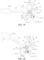
FIG. 20 is a schematic diagram of the locking mechanism in a released state according to Embodiment 2 of the present invention. -
FIG. 21 is a schematic diagram of the locking mechanism returning to the locked state again according to Embodiment 2 of the present invention. - The following describes the present invention in detail with reference to the accompanying drawings and specific implementations.
- Referring to
FIG. 1 to FIG. 9 , a seat rotation locking mechanism is shown, including alocking mechanism 200, where thelocking mechanism 200 is mounted on arotating disc 110 in aseat rotation mechanism 100 to rotate along with therotating disc 110. Twolockholes 121a are uniformly disposed on anouter circumference 121 of a fixeddisc 120 in theseat rotation mechanism 100, and a central angle between the twolockholes 121a is 180°. Each lockhole 121a is a kidney-shaped lockhole, to accommodate two lock pins at the same time. - The
locking mechanism 200 includes alock support 210, twolock pins release lever 260, and a releaselever return spring 270. - The
lock support 210 includes afirst end surface 211 close to theouter circumference 121 of the fixeddisc 120, asecond end surface 212 disposed opposite to thefirst end surface 211, and atop surface 213 connecting thefirst end surface 211 and thesecond end surface 212. - Two through
holes 213a are disposed at one end, close to the center of theseat rotation mechanism 100, of thetop surface 213, twobolts 111 are fixed to therotating disc 110 at the same time, andnuts 112 are tightened after the twobolts 111 passes through the two throughholes 213a, to fixedly mount thelocking mechanism 200 to therotating disc 110. - Two first lock
pin protruding holes first end surface 211 of thelock support 210, and two second lockpin protruding holes second end surface 212 of thelock support 210. The first lockpin protruding hole 211a on thefirst end surface 211 and the second lockpin protruding hole 212a on thesecond end surface 212 are coaxial, and the first lockpin protruding hole 211b on thefirst end surface 211 and the second lockpin protruding hole 212b on thesecond end surface 212 are coaxial. Afirst end 221 and asecond end 222 of onelock pin 220 respectively protrude from the corresponding first lockpin protruding hole 211a and the corresponding second lockpin protruding hole 212a, and afirst end 231 and asecond end 232 of theother lock pin 230 respectively protrude from the corresponding first lockpin protruding hole 211b and the corresponding second lockpin protruding hole 212b. Each of the first ends 221 and 231 of the twolock pins - Releasing
plates lock pins lock pins FIG. 10 andFIG. 11 ), two ends of the two lock pin return springs 240 and 250 are respectively in contact with the releasingplates first end surface 211 of thelock support 210. If the two lock pin return springs 240 and 250 are compression springs, two ends of the two lock pin return springs 240 and 250 are respectively in contact with the releasingplates second end surface 212 of the lock support 210 (as shown inFIG. 13 ). In a locked state, the first ends of the twolock pins outer circumference 121 of the fixeddisc 120 to lock therotating disc 110. - The
release lever 260 includes anoperation end 261 and arelease end 262, anoperation lever sleeve 263 is mounted on theoperation end 261, and two releasingshifting forks release end 262. Arectangular hole 213b is disposed on thetop surface 213 of thelock support 210, and the two releasingshifting forks release end 262 pass through therectangular hole 213b and are respectively forked onto the twolock pins - The
release end 262 of therelease lever 260 is hinged to thetop surface 213 of thelock support 210 through a releaselever rotating shaft 264. The releaselever return spring 270 may be a torsion spring or a tension spring. If the release lever return spring is a torsion spring, the torsion spring is wound around the releaselever rotating shaft 264, one end of the torsion spring acts on therelease lever 260, and the other end acts on thetop surface 213 of thelock support 210. In this embodiment, the releaselever return spring 270 is a tension spring, one end of which is hooked to therelease lever 260, and the other end of which is hooked to thelock support 210. In the locked state, the releaselever return spring 270 may enable therelease lever 260 to be at a locking position all the time. During releasing, the two releasingshifting forks release end 262 of therelease lever 260 drives, through the releasingplates lock pins lock pins outer circumference 121 of the fixeddisc 120 to release therotating disc 110; and the releaselever return spring 270 accumulates energy. - To well insert the first ends of the two
lock pins outer circumference 121 of the fixeddisc 120, in this embodiment, aplastic clip 280 is mounted, by using twoscrews 281, to a position at which the lockhole 121a is disposed on the fixeddisc 120, and a guidingnotch 282 corresponding to the lockhole 121a is disposed on theplastic clip 280. The first ends 221 and 231 of the twolock pins notch 282 in theplastic clip 280. - In this embodiment, a releasing process is that the
operation end 261 of therelease lever 260 is lifted up by using a hand, so that therelease lever 260 rotates around the releaselever rotating shaft 264; and the two releasingshifting forks release end 262 of therelease lever 260 drives, through the releasingplates lock pins lock pins outer circumference 121 of the fixeddisc 120 to release therotating disc 110. - In addition, to eliminate noise generated due to a jolt of the
release lever 260 in a running process, abuffer component 290 is fixed to therelease lever 260. In the locked state, therelease lever 260 is in contact with thelock support 210 through thebuffer component 290, and the noise generated due to the jolt of therelease lever 260 in the running process may be eliminated by fitting in with the releaselever return spring 270. - To alleviate noise generated due to scraping between tips of the first ends 221 and 231 of the two
lock pins outer circumference 121 of the fixeddisc 120 in a rotation process, two methods may be used in this embodiment to solve the problem: One method is that a silencing cap (not shown) is sleeved on the tips of the first ends 221 and 231 of the twolock pins outer circumference 121 of the fixeddisc 120. The other method is that two outward protrudingportions 121b distributed at 180° are disposed on theouter circumference 121 of the fixeddisc 120, each lockhole 121a is disposed on each outward protrudingportion 121b, and each outward protrudingportion 121b is transitionally connected to the remaining part of theouter circumference 121 of the fixeddisc 120 through arc-shaped guiding planes 121c and 121d. Before entering the arc-shaped guiding planes 121c and 121d, the first ends 221 and 231 of the twolock pins outer circumference 121 of the fixeddisc 120, and the first ends 221 and 231 of the twolock pins lock pins outer circumference 121 of the fixeddisc 120 are reduced, thereby effectively reducing noise generated due to scraping. - Referring to
FIG. 10 , before therotating disc 110 rotates to the locking position, the first ends 221 and 231 of the twolock pins guiding plane 121c. In this case, neither of the first ends 221 and 231 of the twolock pins lock pins guiding plane 121c of theouter circumference 121 of the fixeddisc 120. - Referring to
FIG. 11 , with continuous rotation of therotating disc 110, when thefirst end 221 of thefirst lock pin 220 is aligned with the lockhole 121a, under the action of restoring force of the lockpin return spring 240, thefirst end 221 of thefirst lock pin 220 is ejected and inserted into the lockhole 121a, and thefirst end 231 of thesecond lock pin 230 continues to butt against and slide on the arc-shapedguiding plane 121c of theouter circumference 121 of the fixeddisc 120. - Referring to
FIG. 12 , with the continuous rotation of therotating disc 110, thefirst end 231 of thesecond lock pin 230 is also aligned with the lockhole 121a. In this case, thefirst end 221 of thefirst lock pin 220 has come into contact with a hole wall 121aa on one side of the lockhole 121a, and deflects under the action of the hole wall 121aa on this side to make room for insertion of thefirst end 231 of thesecond lock pin 230 into the lockhole 121a, and under the action of restoring force of the lockpin return spring 250, thefirst end 231 of thesecond lock pin 230 is ejected and inserted into the lockhole 121a. - Referring to
FIG. 13 , with the continuous rotation of therotating disc 110, the first ends 221 and 231 of the twolock pins FIG. 13 . Thefirst end 221 of thelock pin 220 forms two contact points a and b with the hole wall 121aa of the lockhole 121a and a hole wall 211aa of the first lockpin protruding hole 211a on thefirst end surface 211 of thelock support 210, and thesecond end 222 of thelock pin 220 forms a third contact point c with a hole wall 212aa of the second lockpin protruding hole 212a on thesecond end surface 212 of thelock support 210. Besides, thefirst end 231 of thelock pin 230 forms two contact points d and e with a hole wall 121ab of the lockhole 121a and a hole wall 211ba of the first lockpin protruding hole 211b on thefirst end surface 211 of thelock support 210, and thesecond end 232 of thelock pin 230 forms a third contact point f with a hole wall 213ba of the second lockpin protruding hole 213b on thesecond end surface 212 of thelock support 210. The twolock pins disc 120 and therotating disc 110 together through the six contact points a, b, c, d, e, and f, thereby effectively eliminating a fit clearance existing after the rotation mechanism is locked, improving a grade of a product, and improving user experience. - In addition, to prevent the
rotating disc 110 from rotating by over 180° to twist off a wire bundle of a seat, in this embodiment, two blockingpoints outer circumference 121 of the fixeddisc 120. The twoblocking points rotating disc 110 to 0 to 180° through the seat rotation locking mechanism. In this way, when theseat rotation mechanism 100 performs rotating adjustment, the rear may only be rotated from the front according to one direction, and then the front is rotated from the rear, thereby avoiding unlimited rotation to twist off the wire bundle of the seat. - To further solve the problem that the tips of the first ends 221 and 231 of the two
lock pins outer circumference 121 of the fixeddisc 120 and scraped, in this embodiment, improvements are further performed to Embodiment 1, and the improvements are as follows: Referring toFIG. 14 , a silencingbushing 124 is disposed in the lockhole 121a, and in the locked state, the first ends 221 and 231 of the twolock pins bushing 124 to lock therotating disc 110. - Referring to
FIG. 15 and FIG. 16 , it is set that an insertion amount of the first ends 221 and 231 of the twolock pins bushing 124 is A2, and a size of a surface difference between the outward protrudingportion 121b on theouter circumference 121 of the fixeddisc 120 and the remaining part of theouter circumference 121 of the fixeddisc 120 is A1, where A1 is greater than A2 by 2.5 mm to 3 mm. In this way, in a process of the rotating adjustment, even if therelease lever 260 is released, there is always a clearance A3 between the tips of the first ends 221 and 231 of the twolock pins outer circumference 121 of the fixeddisc 120, to avoid a case that the tips of the first ends 221 and 231 of the twolock pins outer circumference 121 of the fixeddisc 120 to generate scraping noise, and eliminate an embarrassment that it is inconvenient to lift up the release lever all the time during adjustment outside a car in the prior art. - To implement the foregoing function, in the present invention, the following improvements are performed to the locking mechanism 200: Referring to
FIG. 17 and FIG. 18 , a kidney-shapedhole 213e is disposed on thetop surface 213 of thelock support 210 and acam 300 rotating along with the releaselever rotating shaft 264 is fixed to a shaft end of the releaselever rotating shaft 264 on one side of thetop surface 213 provided with the kidney-shapedhole 213e, where a stoppin avoiding slot 310 and a stoppin limiting slot 320 that are in communication with each other are disposed on thecam 300 and a squeezingshifting plate 400 is disposed axially on thecam 300. - An
axis disposition point 410 between the squeezing shiftingplate 400 and thecam 300 is located on afirst end 420 of the squeezing shiftingplate 400, thefirst end 420 of the squeezing shiftingplate 400 is connected to thelock support 210 through a squeezing shiftingplate return spring 430, and astop pin 450 is fixed between thefirst end 420 and asecond end 440 of the squeezing shiftingplate 400. The squeezing shiftingplate return spring 430 is a compression spring. - In addition, a squeezing
protrusion 121f is disposed at a position, close to the lockhole 121a, on theouter circumference 121 of the fixeddisc 120. - Referring to
FIG. 19 , in the locked state, therelease lever 260 is in the locked state under the action of the releaselever return spring 270, and the twolock pins cam 300 rotates along with the releaselever rotating shaft 264 to the locking position. In this case, under the action of the squeezing shiftingplate return spring 430, thestop pin 450 on the squeezing shiftingplate 400 passes through the stoppin avoiding slot 310 and the kidney-shaped hole 213c and thestop pin 450 is located in the stoppin avoiding slot 310 and at a position of a second end 213bb of the kidney-shaped hole 213c. - Referring to
FIG. 20 , after therelease lever 260 is lifted up to the release position, thecam 300 rotates along with the releaselever rotating shaft 264 to the release position. In this case, thestop pin 450 on the squeezing shiftingplate 400 passes through the stoppin limiting slot 320 and the kidney-shaped hole 213c and thestop pin 450 is limited in the stoppin limiting slot 320 and to a position of a first end 213ba of the kidney-shaped hole 213c, therelease lever 260 is enabled to be at the release position all the time and not return to the locking position even if a hand is released, and the release end of therelease lever 260 drives the twolock pins lock pins outer circumference 121 of the fixeddisc 120 all the time and not scraped. - Referring to
FIG. 21 , when therotating disc 110 rotates to the locking position, thesecond end 440 of the squeezing shiftingplate 400 is in contact with the squeezingprotrusion 121c on theouter circumference 121 of the fixeddisc 120, the squeezing shiftingplate 400 turns over counterclockwise under the action of the squeezingprotrusion 121c, to enable thestop pin 450 to pass through the stoppin avoiding slot 310 and the kidney-shaped hole 213c again and enable thestop pin 450 to be located in the stoppin avoiding slot 310 and at the position of the second end 213bb of the kidney-shaped hole 213c. In this case, the stoppin limiting slot 320 in thecam 300 does not limit thestop pin 450, therelease lever 260 returns to the locking position again under the action of the releaselever return spring 270, and the twolock pins
Claims (12)
- A seat rotation locking mechanism, comprising a locking mechanism (200) mounted on a rotating disc (110) in a seat rotation mechanism (100) and at least one lockhole (121a) disposed on an outer circumference (121) of a fixed disc (120) in the seat rotation mechanism (100), wherein the locking mechanism (200) comprises:a lock support (210) fixed on the rotating disc (110); andat least two lock pins (220, 230) horizontally and moveably configured in the lock support (210), wherein a first end (221, 231) of the lock pin (220, 230) is of a truncated-cone-shaped structure; and the first end (221, 231) of the lock pin (220, 230) is inserted into the lockhole (121a), to implement zero-clearance locking by using wedging between the truncated-cone-shaped structure of the first end (221, 231) of the lock pin (220, 230) and the lockhole (121a);wherein at least one outward protruding portion (121b) is disposed on the outer circumference (121) of the fixed disc (120), the lockhole (121a) is disposed on each outward protruding portion (121b), each outward protruding portion (121b) is transitionally connected to the remaining part of the outer circumference (121) of the fixed disc (120) through an arc-shaped guiding plane (121c, 121d), the first end (221, 231) of the lock pin (220, 230) is not in contact with the remaining part of the outer circumference (121) of the fixed disc (120) before entering the arc-shaped guiding plane (121c, 121d), and the first end (221, 231) of the lock pin (220, 230) is in contact with the arc-shaped guiding plane (121c, 121d) after entering the arc-shaped guiding plane (121c, 121d).
- The seat rotation locking mechanism according to claim 1, further comprising a lock pin return spring (240, 250) sleeved on each lock pin (220, 230), wherein when the lock pin return spring (240, 250) is in a locked state, the first end (221, 231) of the lock pin (220, 230) is inserted, under the action of the lock pin return spring (240, 250), into the lockhole (121a) on the outer circumference (121) of the fixed disc (120) to lock the rotating disc (110).
- The seat rotation locking mechanism according to claim 2, further comprising a release lever (260) hinged to a top surface (213) of the lock support (210) through a release lever rotating shaft (264), wherein the release lever (260) comprises a release end (262) and an operation end, the release lever (260) is driven by operating the operation end of the release lever (260) to rotate, and the release end (262) of the release lever (260) drives the lock pin (220, 230) to move toward a release direction, so that the first end (221, 231) of the lock pin (220, 230) exits from the lockhole (121a) on the outer circumference (121) of the fixed disc (120) to release the rotating disc (110); and
a release lever return spring (270) connected to the release lever (260) and the lock support (210) or the rotating disc (110), wherein the release lever return spring (270) drives the release lever (260) to return to the locked state; and during releasing, the release lever return spring (270) accumulates energy. - The seat rotation locking mechanism according to claim 1, wherein a kidney-shaped hole (213e) is disposed on a top surface (213) of the lock support (210) and a cam (300) rotating along with a release lever rotating shaft (264) is fixed to a shaft end of the release lever rotating shaft (264) on one side of the top surface (213) provided with the kidney-shaped hole (213e), a stop pin avoiding slot (310) and a stop pin limiting slot (320) that are in communication with each other are disposed on the cam (300) and a squeezing shifting plate (400) is disposed axially on the cam (300), an axis disposition point (410) between the squeezing shifting plate (400) and the cam (300) is located on a first end (420) of the squeezing shifting plate (400), the first end (420) of the squeezing shifting plate (400) is connected to the lock support (210) through a squeezing shifting plate return spring (430), and a stop pin (450) is fixed between the first end (420) and a second end (440) of the squeezing shifting plate (400); a squeezing protrusion (121f) is disposed at a position, close to the lockhole (121a), on the outer circumference (121) of the fixed disc (120); after the release lever (260) is lifted to a release position, the cam (300) rotates to the release position along with the release lever rotating shaft (264), in this case, the stop pin (450) on the squeezing shifting plate (400) passes through the stop pin limiting slot (320) and the kidney-shaped hole (213e) and the stop pin (450) is limited in the stop pin limiting slot (320) and to a position of a first end of the kidney-shaped hole (213e), the release lever (260) is enabled to be at a release position all the time and not return to a locking position even if a hand is released, and the release end (262) of the release lever (260) drives the lock pin (220, 230) to be at the release position all the time, so that a tip of the first end (221, 231) of the lock pin (220, 230) is not in contact with the remaining part of the outer circumference (121) of the fixed disc (120) all the time and not scraped; and when the rotating disc (110) rotates to the locking position, the second end (440) of the squeezing shifting plate (400) is in contact with the squeezing protrusion (121f), the squeezing shifting plate (400) turns over under the action of the squeezing protrusion (121f), to enable the stop pin (450) to pass through the stop pin avoiding slot (310) and the kidney-shaped hole (213e) and enable the stop pin (450) to be located in the stop pin avoiding slot (310) and at a position of a second end of the kidney-shaped hole (213e), in this case, the stop pin limiting slot (320) in the cam (300) does not limit the stop pin (450), the release lever (260) returns to the locking position again under the action of the release lever return spring (270), and the lock pin (220, 230) is enabled to return to the locking position under the action of the lock pin return spring (240, 250).
- The seat rotation locking mechanism according to any one of claims 1 to 4, wherein a silencing bushing (124) is disposed in the lockhole (121a), and in the locked state, the first end (221, 231) of the lock pin (220, 230) is inserted into the silencing bushing (124) under the action of the lock pin return spring (240, 250) to lock the rotating disc (110).
- The seat rotation locking mechanism according to any one of claims 1 to 4, wherein a plastic clip (280) is mounted to a position at which a lockhole (121a) is disposed on the fixed disc (120), a guiding notch corresponding to the lockhole (121a) is disposed on the plastic clip (280), and the first end (221, 231) of the lock pin (220, 230) enters the lockhole (121a) through bottom guidance of the guiding notch in the plastic clip (280).
- The seat rotation locking mechanism according to claim 3, wherein a silencing cap is sleeved on a tip of the first end (221, 231) of the lock pin (220, 230), and the silencing cap is in contact with the outer circumference (121) of the fixed disc (120).
- The seat rotation locking mechanism according to claim 3, wherein a buffer component (290) is fixed to the release lever (260), and in the locked state, the release lever (260) is in contact with the lock support (210) through the buffer component (290), to eliminate noise generated due to a jolt of the release lever (260) in a running process.
- The seat rotation locking mechanism according to claim 3, wherein the lock support (210) comprises a first end surface (211) close to the outer circumference (121) of the fixed disc (120), a second end surface (212) disposed opposite to the first end surface (211), and a top surface connecting the first end surface (211) and the second end surface (212); at least two first lock pin protruding holes (211a, 211b) are disposed on the first end surface (211), at least two second lock pin protruding holes (212a, 212b) are disposed on the second end surface (212), and the first lock pin protruding holes (211a, 211b) on the first end surface (211) and the second lock pin protruding holes (212a, 212b) on the second end surface (212) are in a one-to-one correspondence and coaxial; and a first end (221, 231) and a second end of each lock pin (220, 230) respectively protrude from a corresponding first lock pin protruding hole (211a, 211b) and a corresponding second lock pin protruding hole (212a, 212b).
- The seat rotation locking mechanism according to claim 9, wherein a releasing plate (223, 233) is fixed to each lock pin (220, 230), one end of the lock pin return spring (240, 250) is in contact with the releasing plate (223, 233), and the other end is in contact with the first end surface (211) or the second end surface (212); in the locked state, the release end (262) of the release lever (260) is not in contact with the releasing plate (23, 233), in a released state, the release end (262) of the release lever (260) is in contact with the releasing plate (223, 233) and drives the lock pin (220, 230), through the releasing plate (223, 233), to move toward the release direction, and when the release lever (260) is located at a middle position, the release end (262) of the release lever (260) is in contact with the releasing plate (223, 233) and drives the lock pin (220, 230), through the releasing plate (223, 233), to move toward the release direction.
- The seat rotation locking mechanism according to claim 10, wherein at least two releasing shifting forks (262a, 262b) are disposed at the release end (262) of the release lever (260), each releasing shifting fork (262a, 262b) corresponds to one lock pin (220, 230), in the locked state, the releasing shifting fork (262a, 262b) is not in contact with the releasing plate (223, 233), in the released state, the releasing shifting fork (262a, 262b) is in contact with the releasing plate (223, 233) and drives the lock pin (220, 230), through the releasing plate (223, 233), to move toward the release direction, and when the release lever (260) is located at the middle position, the releasing shifting fork (262a, 262b) is in contact with the releasing plate (223, 233) and drives the lock pin (220, 230), through the releasing plate (223, 233), to move toward the release direction.
- The seat rotation locking mechanism according to claim 3, wherein two blocking points (122, 123) are disposed on the outer circumference (121) of the fixed disc (120), and the two blocking points (122, 123) are arranged at 180° and fit in with the seat rotation locking mechanism, to limit a rotation angle of the rotating disc (110) to 0 to 180° through the seat rotation locking mechanism.
Applications Claiming Priority (2)
| Application Number | Priority Date | Filing Date | Title |
|---|---|---|---|
| CN201810847736.0A CN108968465A (en) | 2018-07-27 | 2018-07-27 | A kind of seat rotary locking mechanism |
| PCT/CN2019/086227 WO2020019827A1 (en) | 2018-07-27 | 2019-05-09 | Seat rotation locking mechanism |
Publications (3)
| Publication Number | Publication Date |
|---|---|
| EP3831245A1 EP3831245A1 (en) | 2021-06-09 |
| EP3831245A4 EP3831245A4 (en) | 2022-04-20 |
| EP3831245B1 true EP3831245B1 (en) | 2023-10-04 |
Family
ID=64550318
Family Applications (1)
| Application Number | Title | Priority Date | Filing Date |
|---|---|---|---|
| EP19842123.2A Active EP3831245B1 (en) | 2018-07-27 | 2019-05-09 | Seat rotation locking mechanism |
Country Status (4)
| Country | Link |
|---|---|
| US (1) | US11858382B2 (en) |
| EP (1) | EP3831245B1 (en) |
| CN (1) | CN108968465A (en) |
| WO (1) | WO2020019827A1 (en) |
Families Citing this family (4)
| Publication number | Priority date | Publication date | Assignee | Title |
|---|---|---|---|---|
| CN209474126U (en) * | 2018-07-27 | 2019-10-11 | 延锋安道拓座椅有限公司 | A kind of rotary seat gapless lockable mechanism |
| CN108968465A (en) * | 2018-07-27 | 2018-12-11 | 延锋安道拓座椅有限公司 | A kind of seat rotary locking mechanism |
| CN114028149A (en) * | 2021-11-09 | 2022-02-11 | 杭州杰莺医疗科技有限公司 | Electric chair rotary positioning device |
| CN114043219A (en) * | 2021-11-12 | 2022-02-15 | 苏州浪潮智能科技有限公司 | Server assembled cylinder index plate |
Citations (1)
| Publication number | Priority date | Publication date | Assignee | Title |
|---|---|---|---|---|
| WO2006041570A1 (en) * | 2004-10-08 | 2006-04-20 | B/E Aerospace, Inc. | Moveable seat with tapered swivel assembly and cable track wheel |
Family Cites Families (27)
| Publication number | Priority date | Publication date | Assignee | Title |
|---|---|---|---|---|
| US3910633A (en) | 1974-05-09 | 1975-10-07 | Garrett Tubular Products Inc | Swivel chair with lockable swiveling mechanism |
| US3975050A (en) * | 1975-05-14 | 1976-08-17 | Mckee Dale P | Tilting swivel chair support |
| US4671572A (en) * | 1983-12-23 | 1987-06-09 | Erda, Inc. | Adjustable chair having roller cam adjustment mechanism |
| CA2015353A1 (en) * | 1989-12-04 | 1991-06-04 | Dennis J. Gryp | Swivel seat, especially for vehicles |
| US6021989A (en) * | 1996-12-16 | 2000-02-08 | Toyota Shatai Kabushiki Kaisha | Swivel assembly of a vehicle seat |
| US6361111B1 (en) * | 1998-11-18 | 2002-03-26 | Electric Mobility Corporation | Rotational adjustment device |
| JP2004008443A (en) | 2002-06-06 | 2004-01-15 | Kariya Mokuzai Kogyo Kk | Turn-table and chair using the same |
| KR100799874B1 (en) | 2006-08-23 | 2008-01-31 | 주식회사다스 | Seat swivel for vehicle |
| JP4305675B2 (en) * | 2007-03-02 | 2009-07-29 | トヨタ車体株式会社 | Vehicle seat |
| FR2930203B1 (en) * | 2008-04-22 | 2010-05-21 | Faurecia Sieges Automobile | SLIDER FOR A MOTOR VEHICLE SEAT AND METHOD OF ASSEMBLING SUCH A SLIDER |
| US8382057B2 (en) * | 2010-03-31 | 2013-02-26 | Crh North America, Inc. | Low profile seat track system |
| CN102180111B (en) * | 2011-04-20 | 2012-10-10 | 苏州忠明祥和精工有限公司 | Disc type gapless angle adjuster |
| WO2013116531A1 (en) * | 2012-01-31 | 2013-08-08 | Caterpillar Inc. | Electro-mechanical seat swivel system |
| CN102529756A (en) | 2012-03-02 | 2012-07-04 | 北京北方车辆集团有限公司 | Novel rotator mechanism of rotating chair |
| CN202641426U (en) | 2012-06-12 | 2013-01-02 | 浙江龙生汽车部件股份有限公司 | Business purpose vehicle middle seat turntable device |
| DE102012112529B3 (en) | 2012-12-18 | 2014-03-20 | Grammer Ag | Commercial vehicle seat with a locking element |
| US9265349B1 (en) * | 2014-03-16 | 2016-02-23 | Valerie Jensen | Multi-directional and side glider chair |
| CN104670256B (en) | 2014-12-22 | 2017-05-03 | 上海坦达轨道车辆座椅系统有限公司 | Seat rotating mechanism |
| KR101643889B1 (en) * | 2014-12-30 | 2016-08-01 | 현대다이모스(주) | Apparatus for locking seat-rail in vehicle |
| CN104924926B (en) | 2015-06-29 | 2017-05-10 | 成都市天龙交通设备有限公司 | Rotating mechanism of seat |
| CN106427682A (en) | 2016-11-24 | 2017-02-22 | 江苏忠明祥和精工股份有限公司 | Turnplate for automobile seat |
| CN206520509U (en) | 2017-01-07 | 2017-09-26 | 重庆长越汽车内饰件有限公司 | A kind of rotating vehicle seat |
| CN206942637U (en) * | 2017-07-10 | 2018-01-30 | 浙江洋铭实业有限公司 | Telescopic folding carwash platform |
| CN207725260U (en) * | 2017-11-28 | 2018-08-14 | 延锋安道拓座椅有限公司 | A kind of locking system |
| CN107953806B (en) * | 2017-11-28 | 2020-04-07 | 延锋安道拓座椅有限公司 | Automobile seat rotating mechanism |
| CN209474126U (en) * | 2018-07-27 | 2019-10-11 | 延锋安道拓座椅有限公司 | A kind of rotary seat gapless lockable mechanism |
| CN108968465A (en) | 2018-07-27 | 2018-12-11 | 延锋安道拓座椅有限公司 | A kind of seat rotary locking mechanism |
-
2018
- 2018-07-27 CN CN201810847736.0A patent/CN108968465A/en active Pending
-
2019
- 2019-05-09 WO PCT/CN2019/086227 patent/WO2020019827A1/en unknown
- 2019-05-09 US US17/263,390 patent/US11858382B2/en active Active
- 2019-05-09 EP EP19842123.2A patent/EP3831245B1/en active Active
Patent Citations (2)
| Publication number | Priority date | Publication date | Assignee | Title |
|---|---|---|---|---|
| WO2006041570A1 (en) * | 2004-10-08 | 2006-04-20 | B/E Aerospace, Inc. | Moveable seat with tapered swivel assembly and cable track wheel |
| US20060108848A1 (en) * | 2004-10-08 | 2006-05-25 | B/E Aerospace, Inc. | Moveable seat with tapered swivel assembly and cable track wheel |
Also Published As
| Publication number | Publication date |
|---|---|
| WO2020019827A1 (en) | 2020-01-30 |
| EP3831245A1 (en) | 2021-06-09 |
| US20210162890A1 (en) | 2021-06-03 |
| CN108968465A (en) | 2018-12-11 |
| US11858382B2 (en) | 2024-01-02 |
| EP3831245A4 (en) | 2022-04-20 |
Similar Documents
| Publication | Publication Date | Title |
|---|---|---|
| EP3831245B1 (en) | Seat rotation locking mechanism | |
| US5482345A (en) | Van-type vehicle seat front riser latch system | |
| KR100513576B1 (en) | Round type recliner for vehicles | |
| KR102110134B1 (en) | Hinge device of console armrest for car | |
| EP0839686A2 (en) | Seat reclining device. | |
| EP0716980A1 (en) | Crashworthy aircraft seat with a harness | |
| EP3831244B1 (en) | Non-clearance locking mechanism of rotating seat | |
| US4236753A (en) | Seat reclining apparatus | |
| CN214189416U (en) | Manual upset headrest of car seat | |
| KR102230108B1 (en) | Sliding locking armrest for vehicle | |
| CN212243070U (en) | Support arrangement for car headrest | |
| CN211442066U (en) | Light automobile seat backrest lock | |
| WO2013144527A1 (en) | Hinge assembly for a vehicle seat | |
| KR101653705B1 (en) | Clutching device for a vehicle armrest assembly | |
| CN107415781B (en) | A kind of easy access mechanism for automotive seat | |
| WO2019242202A1 (en) | Head support mounting structure for child seat | |
| KR200313604Y1 (en) | Round type recliner for vehicles | |
| CN107554360B (en) | Unlocking device and seat | |
| EP3350016B1 (en) | Bi-position locking device of a rear seat backrest of an automotive vehicle | |
| CN219257128U (en) | Automobile safety seat | |
| CN109362246A (en) | A kind of energy-saving type multifunctional small tiller | |
| CN218172052U (en) | Unlocking mechanism of easy-entry seat | |
| CN213811952U (en) | Arrow rest capable of improving shooting accuracy | |
| CN218616352U (en) | Automobile seat slide way | |
| CN218368074U (en) | Compact type three-wheel recreational vehicle seat overturning and sliding device |
Legal Events
| Date | Code | Title | Description |
|---|---|---|---|
| STAA | Information on the status of an ep patent application or granted ep patent |
Free format text: STATUS: THE INTERNATIONAL PUBLICATION HAS BEEN MADE |
|
| PUAI | Public reference made under article 153(3) epc to a published international application that has entered the european phase |
Free format text: ORIGINAL CODE: 0009012 |
|
| STAA | Information on the status of an ep patent application or granted ep patent |
Free format text: STATUS: REQUEST FOR EXAMINATION WAS MADE |
|
| 17P | Request for examination filed |
Effective date: 20210209 |
|
| AK | Designated contracting states |
Kind code of ref document: A1 Designated state(s): AL AT BE BG CH CY CZ DE DK EE ES FI FR GB GR HR HU IE IS IT LI LT LU LV MC MK MT NL NO PL PT RO RS SE SI SK SM TR |
|
| DAV | Request for validation of the european patent (deleted) | ||
| DAX | Request for extension of the european patent (deleted) | ||
| RAP3 | Party data changed (applicant data changed or rights of an application transferred) |
Owner name: YANFENG INTERNATIONAL SEATING SYSTEMS CO., LTD. |
|
| A4 | Supplementary search report drawn up and despatched |
Effective date: 20220318 |
|
| RIC1 | Information provided on ipc code assigned before grant |
Ipc: B60N 2/14 20060101ALI20220314BHEP Ipc: A47C 3/18 20060101AFI20220314BHEP |
|
| GRAP | Despatch of communication of intention to grant a patent |
Free format text: ORIGINAL CODE: EPIDOSNIGR1 |
|
| STAA | Information on the status of an ep patent application or granted ep patent |
Free format text: STATUS: GRANT OF PATENT IS INTENDED |
|
| INTG | Intention to grant announced |
Effective date: 20230522 |
|
| GRAS | Grant fee paid |
Free format text: ORIGINAL CODE: EPIDOSNIGR3 |
|
| GRAA | (expected) grant |
Free format text: ORIGINAL CODE: 0009210 |
|
| STAA | Information on the status of an ep patent application or granted ep patent |
Free format text: STATUS: THE PATENT HAS BEEN GRANTED |
|
| AK | Designated contracting states |
Kind code of ref document: B1 Designated state(s): AL AT BE BG CH CY CZ DE DK EE ES FI FR GB GR HR HU IE IS IT LI LT LU LV MC MK MT NL NO PL PT RO RS SE SI SK SM TR |
|
| REG | Reference to a national code |
Ref country code: GB Ref legal event code: FG4D |
|
| REG | Reference to a national code |
Ref country code: CH Ref legal event code: EP |
|
| REG | Reference to a national code |
Ref country code: IE Ref legal event code: FG4D |
|
| REG | Reference to a national code |
Ref country code: DE Ref legal event code: R096 Ref document number: 602019038817 Country of ref document: DE |
|
| REG | Reference to a national code |
Ref country code: LT Ref legal event code: MG9D |
|
| REG | Reference to a national code |
Ref country code: NL Ref legal event code: MP Effective date: 20231004 |
|
| REG | Reference to a national code |
Ref country code: AT Ref legal event code: MK05 Ref document number: 1616793 Country of ref document: AT Kind code of ref document: T Effective date: 20231004 |
|
| PG25 | Lapsed in a contracting state [announced via postgrant information from national office to epo] |
Ref country code: NL Free format text: LAPSE BECAUSE OF FAILURE TO SUBMIT A TRANSLATION OF THE DESCRIPTION OR TO PAY THE FEE WITHIN THE PRESCRIBED TIME-LIMIT Effective date: 20231004 |
|
| PG25 | Lapsed in a contracting state [announced via postgrant information from national office to epo] |
Ref country code: GR Free format text: LAPSE BECAUSE OF FAILURE TO SUBMIT A TRANSLATION OF THE DESCRIPTION OR TO PAY THE FEE WITHIN THE PRESCRIBED TIME-LIMIT Effective date: 20240105 |
|
| PG25 | Lapsed in a contracting state [announced via postgrant information from national office to epo] |
Ref country code: IS Free format text: LAPSE BECAUSE OF FAILURE TO SUBMIT A TRANSLATION OF THE DESCRIPTION OR TO PAY THE FEE WITHIN THE PRESCRIBED TIME-LIMIT Effective date: 20240204 |
|
| PG25 | Lapsed in a contracting state [announced via postgrant information from national office to epo] |
Ref country code: LT Free format text: LAPSE BECAUSE OF FAILURE TO SUBMIT A TRANSLATION OF THE DESCRIPTION OR TO PAY THE FEE WITHIN THE PRESCRIBED TIME-LIMIT Effective date: 20231004 |
|
| PG25 | Lapsed in a contracting state [announced via postgrant information from national office to epo] |
Ref country code: AT Free format text: LAPSE BECAUSE OF FAILURE TO SUBMIT A TRANSLATION OF THE DESCRIPTION OR TO PAY THE FEE WITHIN THE PRESCRIBED TIME-LIMIT Effective date: 20231004 |