EP3829963B1 - Fahrzeug mit hinterer unterbodenverkleidung mit einer abfasung - Google Patents
Fahrzeug mit hinterer unterbodenverkleidung mit einer abfasung Download PDFInfo
- Publication number
- EP3829963B1 EP3829963B1 EP19748581.6A EP19748581A EP3829963B1 EP 3829963 B1 EP3829963 B1 EP 3829963B1 EP 19748581 A EP19748581 A EP 19748581A EP 3829963 B1 EP3829963 B1 EP 3829963B1
- Authority
- EP
- European Patent Office
- Prior art keywords
- deflector
- vehicle
- fixing
- chamfer
- edge
- Prior art date
- Legal status (The legal status is an assumption and is not a legal conclusion. Google has not performed a legal analysis and makes no representation as to the accuracy of the status listed.)
- Active
Links
- 238000000034 method Methods 0.000 claims description 11
- -1 polypropylene Polymers 0.000 claims description 7
- 239000004696 Poly ether ether ketone Substances 0.000 claims description 6
- 239000004952 Polyamide Substances 0.000 claims description 6
- 239000004697 Polyetherimide Substances 0.000 claims description 6
- 239000004954 Polyphthalamide Substances 0.000 claims description 6
- 239000004743 Polypropylene Substances 0.000 claims description 6
- 229920002647 polyamide Polymers 0.000 claims description 6
- 229920002530 polyetherether ketone Polymers 0.000 claims description 6
- 229920001601 polyetherimide Polymers 0.000 claims description 6
- 229920006375 polyphtalamide Polymers 0.000 claims description 6
- 229920001155 polypropylene Polymers 0.000 claims description 6
- 230000003584 silencer Effects 0.000 claims description 6
- 238000004519 manufacturing process Methods 0.000 claims description 4
- 238000000465 moulding Methods 0.000 claims description 4
- 239000004962 Polyamide-imide Substances 0.000 claims description 3
- 239000004676 acrylonitrile butadiene styrene Substances 0.000 claims description 3
- 229920002312 polyamide-imide Polymers 0.000 claims description 3
- 239000012815 thermoplastic material Substances 0.000 claims description 3
- 125000000843 phenylene group Chemical group C1(=C(C=CC=C1)*)* 0.000 claims 1
- 229920001021 polysulfide Polymers 0.000 claims 1
- 239000005077 polysulfide Substances 0.000 claims 1
- 150000008117 polysulfides Polymers 0.000 claims 1
- 238000003780 insertion Methods 0.000 description 4
- 230000037431 insertion Effects 0.000 description 4
- 230000000295 complement effect Effects 0.000 description 2
- 238000009434 installation Methods 0.000 description 2
- 238000003801 milling Methods 0.000 description 2
- 229920003023 plastic Polymers 0.000 description 2
- 239000004033 plastic Substances 0.000 description 2
- 229920000265 Polyparaphenylene Polymers 0.000 description 1
- 239000004734 Polyphenylene sulfide Substances 0.000 description 1
- UCKMPCXJQFINFW-UHFFFAOYSA-N Sulphide Chemical compound [S-2] UCKMPCXJQFINFW-UHFFFAOYSA-N 0.000 description 1
- 238000004026 adhesive bonding Methods 0.000 description 1
- 239000000463 material Substances 0.000 description 1
- 238000005457 optimization Methods 0.000 description 1
- 229920000069 polyphenylene sulfide Polymers 0.000 description 1
- 230000001681 protective effect Effects 0.000 description 1
- 230000035939 shock Effects 0.000 description 1
Images

Classifications
-
- B—PERFORMING OPERATIONS; TRANSPORTING
- B62—LAND VEHICLES FOR TRAVELLING OTHERWISE THAN ON RAILS
- B62D—MOTOR VEHICLES; TRAILERS
- B62D35/00—Vehicle bodies characterised by streamlining
- B62D35/02—Streamlining the undersurfaces
-
- Y—GENERAL TAGGING OF NEW TECHNOLOGICAL DEVELOPMENTS; GENERAL TAGGING OF CROSS-SECTIONAL TECHNOLOGIES SPANNING OVER SEVERAL SECTIONS OF THE IPC; TECHNICAL SUBJECTS COVERED BY FORMER USPC CROSS-REFERENCE ART COLLECTIONS [XRACs] AND DIGESTS
- Y02—TECHNOLOGIES OR APPLICATIONS FOR MITIGATION OR ADAPTATION AGAINST CLIMATE CHANGE
- Y02T—CLIMATE CHANGE MITIGATION TECHNOLOGIES RELATED TO TRANSPORTATION
- Y02T10/00—Road transport of goods or passengers
- Y02T10/80—Technologies aiming to reduce greenhouse gasses emissions common to all road transportation technologies
- Y02T10/82—Elements for improving aerodynamics
-
- Y—GENERAL TAGGING OF NEW TECHNOLOGICAL DEVELOPMENTS; GENERAL TAGGING OF CROSS-SECTIONAL TECHNOLOGIES SPANNING OVER SEVERAL SECTIONS OF THE IPC; TECHNICAL SUBJECTS COVERED BY FORMER USPC CROSS-REFERENCE ART COLLECTIONS [XRACs] AND DIGESTS
- Y02—TECHNOLOGIES OR APPLICATIONS FOR MITIGATION OR ADAPTATION AGAINST CLIMATE CHANGE
- Y02T—CLIMATE CHANGE MITIGATION TECHNOLOGIES RELATED TO TRANSPORTATION
- Y02T10/00—Road transport of goods or passengers
- Y02T10/80—Technologies aiming to reduce greenhouse gasses emissions common to all road transportation technologies
- Y02T10/88—Optimized components or subsystems, e.g. lighting, actively controlled glasses
Definitions
- the invention lies in the field of vehicles and, more particularly, motor vehicles.
- the invention relates to a vehicle having an underfloor deflector arranged at the rear of the vehicle.
- Rear underfloor deflectors are aerodynamically shaped parts intended to improve the airflow characteristics of the rear part of the vehicle.
- the sub-floor deflectors are panels, generally made of plastic material, also having the function of a protective shield against gravel from the elements of the vehicle located under the floor, such as, for example, a propulsion battery.
- This type of deflector generally comprises a front portion adapted to be connected to the underbody of the vehicle and a rear portion adapted to be connected to a rear bumper of the vehicle.
- the document EP1612128 describes a vehicle equipped with an underbody structure including a floor panel whose rear part is raised to form a rear floor, a pair of rear side structures extending along a longitudinal axis of the vehicle at the rear of the floor panel.
- the patent DE102005030419 describes a vehicle, in particular an all-terrain vehicle or pickup, equipped with an anti-underrun device comprising a deflector plate mounted under the body of the vehicle.
- the invention aims to create an improved anti-underrun device.
- the deflector plate is mounted under the body in a movable manner between an input position and an output position.
- FR2987806 And FR2987805 describe the preamble of the independent claim, describe an assembly between a first deflector and a fairing located under the vehicle, at the rear of said vehicle, fixed to a crossmember.
- the object of the invention is to respond to at least one of the drawbacks of the prior art by proposing a mounting method and a vehicle configured to facilitate the mounting of a deflector on the bumper and in particular of a deflector under -rear floor on a rear bumper skirt and on a rear panel.
- the subject of the invention is a vehicle comprising a rear underbody panel, a rear bumper skirt and a rear sub-floor deflector, said rear panel and said skirt having fixing lugs , the deflector comprising a rear edge showing an edge and at least one fixing interface arranged interposed between the fixing lugs of the rear underbody panel and the fixing lugs of the bumper skirt; the vehicle is remarkable in that the section of the edge of the deflector has at least one chamfer at one of its attachment interfaces in order to guide said rear edge of the deflector during its assembly.
- the invention consists in providing the rear edge of the deflector with at least one chamfer so as to assist the insertion of said edge into the air gap formed by the mounting tabs of the rear underbody panel and those of the bumper skirt.
- the presence of a chamfer makes it possible to guide the deflector, the rear edge of which risks coming into abutment against the free end of one of said fixing lugs so that it is positioned correctly between the two fixing lugs and not, for example, above the bumper valance mounting bracket or below the underbody rear panel mounting bracket.
- the rear sub-floor deflector being in the form of a plate showing an upper face and a lower face, the lower face being oriented to be placed facing the ground, the vehicle is remarkable in that the said chamfer(s) are arranged on the upper face.
- the rear sub-floor deflector being in the form of a plate showing an upper face and a lower face, the lower face being oriented to be placed facing the ground, the vehicle is remarkable in that the or said chamfers are arranged on the underside.
- the deflector shows at least one of its fixing interfaces a zone of reduced thickness opening onto the edge of said deflector, and the fixing interface has a chamfer on either side of said zone of reduced thickness along the transverse direction of the vehicle.
- the rear underbody panel, the rear bumper skirt and the rear subfloor deflector are fixed together by fixing means passing through openings shown by the fixing lugs and the fixing interfaces.
- the invention relates to a deflector for a vehicle according to the first aspect; the deflector showing an upper face and a lower face, the lower face being intended to be placed facing the ground, the deflector is remarkable in that it comprises at least one attachment interface to a rear base panel and to a skirt rear bumper, and in that it has at least one chamfer at one of its fixing interfaces in order to guide said edge of the deflector during its assembly.
- the said chamfer(s) are arranged on the upper face.
- the deflector has stiffening ribs at at least one of its fixing interfaces.
- the subject of the invention is a method for manufacturing a deflector according to the second aspect, the method being remarkable in that it comprises the production by molding of a chamfer on the rear edge of said deflector at the level of one of its fixing interfaces.
- said deflector is made of a thermoplastic material chosen from acrylonitrile butadiene styrene (ABS), polypropylene (PP), polyphthalamide (PPA), polyetheretherketone (PEEK), polyphenylene sulphide (PPS), polyamide- imide (PAl), polyetherimide (PEI), polyarylamide (PAA), and/or polyamide (PA).
- the deflector is put in place by a movement from front to back while being inclined with respect to its final position.
- the term “comprise” is synonymous with “include” and is not limiting in that it authorizes the presence of other elements in the vehicle, the bumper skirt or the rear panel of foundation to which it refers. It is understood that the term “include” includes the terms “consist of”. In the various figures, the same references designate identical or similar elements.
- the terms “lower”, “upper”, “front”, “rear” will be understood in relation to the general orientation of the vehicle. The terms “lower” and “low” will indicate a greater proximity to the ground in the vertical direction than the terms “upper” or “high”.
- front will indicate a positioning oriented towards the front of a vehicle in the horizontal direction and the term “rear” will indicate a positioning oriented towards the rear of a vehicle in the same direction.
- rear will indicate a positioning oriented towards the rear of a vehicle in the same direction.
- FIG. 1 illustrating a vehicle 1 according to the invention, as seen from below during the fitting of a deflector 7 under the rear floor.
- the vehicle 1 comprises a floor 33, a silencer 31, a rear underbody panel 3, a bumper skirt 5 and a deflector 7.
- the rear panel 3 and the bumper skirt 5 each have at least one fixing lug (15, 17) and, preferably, at least two lugs. When they have two or more fixing lugs, these are distributed over the element showing them in the transverse direction of the vehicle 1.
- the fixing lugs (15, 17) are arranged opposite one with respect to the each other and are spaced in the vertical direction of said vehicle so as to show an air gap before their final assembly.
- the deflector 7 comprises a front portion adapted to be connected to the floor 33 of the vehicle, and a rear portion adapted to be connected to a rear bumper of the vehicle.
- the rear edge 9 of the deflector 7 shows an edge 11 and at least one fixing interface 13 arranged to fit between the fixing lugs 17 of the rear panel 3 of the base and the fixing lugs 15 of the skirt 5 of the bumper. shocks.
- the deflector comprises at least one fixing interface 13 and, preferably, at least two fixing interfaces 13. Said interfaces 13 are positioned on the rear edge 9 to face the fixing lugs 17 of the rear panel 3 and the lugs of attachment 15 of the bumper skirt 5.
- the fixing interface is sized to fit “sandwichically” into the air gap formed by said pair of fixing lugs (15, 17) before final assembly.
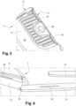
- the edge 11 of the rear edge 9 of the deflector 7 has at least one chamfer 19 at one of its fixing interfaces 13 in order to guide the said edge 9 of the deflector 7 during its assembly, as illustrated in figures 3 and 4 .
- the chamfer 19 has the function of assisting the insertion of said edge 9 in the air gap formed by the fixing lugs (15, 17) of the rear panel 3 of the base and those of the skirt 5 of the bumper.
- the presence of a chamfer 19 makes it possible to guide the deflector 7 in order to prevent its rear edge 9 from coming into abutment against the free end of the fixing lug 17 of the rear panel 3.
- the presence of the chamfer 19 facilitates a sliding movement along said tab 17 and ensures that the rear edge 9 of the deflector 7 passes below the fixing tab 17 of the rear panel 3 and not above. In the absence of such a chamfer 19, the rear edge of the deflector 7 would abut against the fixing lug 17 and would be difficult to mount by the operator, or even could no longer be introduced into its location.
- Each attachment interface of the deflector 7 therefore has at least one chamfer 19 and, preferably, has two.
- the rear subfloor deflector 7 is in the form of a plate showing an upper face 23 and a lower face 21, the lower face 21 (illustrated in figure 1 ) being oriented to face the ground.
- the said bevel(s) 19 are arranged on the upper face 23, as illustrated in picture 3 .
- the said chamfer(s) are arranged on the lower face.
- the deflector 7 shows, at the level of at least one of its attachment interfaces 13, a zone of reduced thickness opening onto the edge 9 of said deflector 7.
- each interface has such a zone of reduced thickness.
- Said zone is bordered on either side by a chamfer 19 in the transverse direction of the vehicle. It is this zone of reduced thickness which is arranged facing the fixing lugs (15, 17).
- the fixing interface 13 and the fixing lugs show an opening (25, 27, 29), the three openings being arranged aligned in the vertical direction of the vehicle.
- a fixing means such as a screw-nut system, will pass through the three openings in order to assemble them.
- the assembly can be carried out, for example, by gluing.
- the deflector 7 advantageously has stiffening ribs at at least one of its fixing interfaces 13. Their presence serves to distribute the force undergone by the part during a rear impact and, thus, to protect the surrounding elements. sensitive, such as the silencer 31.
- the deflector 7 is made by molding, and the chamfer(s) 19 will be made directly by molding and not by subsequent milling.
- the person skilled in the art can also choose to produce them by milling.
- Said deflector 7 is made of a plastic and, preferably, thermoplastic material chosen from acrylonitrile butadiene styrene (ABS), polypropylene (PP), polyphthalamide (PPA), polyetheretherketone (PEEK), polyphenylene sulfide (PPS) , polyamide-imide (PAl), polyetherimide (PEI), polyarylamide (PAA), and/or polyamide (PA).
- ABS acrylonitrile butadiene styrene
- PP polypropylene
- PPA polyphthalamide
- PEEK polyetheretherketone
- PPS polyphenylene sulfide
- PAl polyamide-imide
- PEI polyetherimide
- PAA polyarylamide
- PA polyamide
- the operator To mount the deflector 7 in a vehicle 1, the operator must first proceed with the partial assembly of the bumper skirt 5 on the vehicle 1, set up the deflector 7 by inserting its rear edge 9 between the tabs fixing 15 of the skirt 5 of the bumper and the fixing lugs 17 of the rear panel 3 and fixing them together.
- the deflector 7 is put in place by a movement from front to back while being inclined with respect to its final position. Its oblique positioning is preferable when a plurality of studs (not shown) extend from the surface of the floor 33, said studs therefore being configured to be assembled with the front part of the deflector 7.
- At least one fixing lug 17 of the rear panel 3 cooperates with a chamfer 19 of said deflector 7.
- the chamfer will slide along said lug 17 to allow the insertion of the fixing interface 13 in the air gap previously created between the fixing lugs (15, 17).
Landscapes
- Engineering & Computer Science (AREA)
- Chemical & Material Sciences (AREA)
- Combustion & Propulsion (AREA)
- Transportation (AREA)
- Mechanical Engineering (AREA)
- Body Structure For Vehicles (AREA)
Claims (10)
- Fahrzeug (1) mit einer hinteren Bodenplatte (3), einer hinteren Stoßfängerschürze (5) und einer hinteren Unterbodenablenkplatte (7), wobei die hintere Bodenplatte (3) und die Schürze (5) Befestigungslaschen (15, 17) aufweisen, wobei die Ablenkplatte (7) eine hintere Kante (9), die eine Scheibe (11) aufweist, und mindestens eine Befestigungsschnittstelle (13) aufweist, die zwischen den Befestigungslaschen (17) der hinteren Bodenplatte (3) und den Befestigungslaschen (15) der Schürze (5) angeordnet ist Stoßfänger; das Fahrzeug (1) ist dadurch gekennzeichnet, dass die Kante (11) des Randes (9) des Deflektors (7) mindestens eine Abschrägung (19) an einer ihrer Befestigungsschnittstellen (13) aufweist, um den hinteren Rand (9) des Deflektors (7) bei seiner Montage zu führen.
- Fahrzeug (1) nach Anspruch 1, wobei die hintere Ablenkplatte (7) in Form einer Platte vorliegt, die eine Oberseite (23) und eine Unterseite (21) aufweist, wobei die Unterseite (21) so ausgerichtet ist, dass sie dem Boden zugewandt ist, und das Fahrzeug (1) dadurch gekennzeichnet ist, dass die Abschrägung oder die Abschrägungen (19) auf der Oberseite (23) angeordnet sind.
- Fahrzeug (1) nach Anspruch 1 oder 2, wobei die hintere Ablenkplatte (7) in Form einer Platte vorliegt, die eine Oberseite (23) und eine Unterseite (21) aufweist, wobei die Unterseite (21) so ausgerichtet ist, dass sie dem Boden zugewandt ist, und das Fahrzeug (1) dadurch gekennzeichnet ist, dass die wenigstens eine Abschrägung (19) auf der Unterseite (21) angeordnet ist.
- Fahrzeug (1) nach einem der Ansprüche 1 bis 3, dadurch gekennzeichnet, dass der Abweiser (7) an mindestens einer seiner Befestigungsschnittstellen (13) eine Zone mit verringerter Dicke aufweist, die auf den Rand (9) des Abweisers (7) mündet, und dass die Befestigungsschnittstelle (13) eine Abschrägung (19) auf beiden Seiten der Zone mit verringerter Dicke in der Querrichtung des Fahrzeugs aufweist.
- Fahrzeug (1) nach einem der Ansprüche 1 bis 4, dadurch gekennzeichnet, dass die hintere Bodenplatte (3), die hintere Stoßfängerschürze (5) und der hintere Unterbodenabweiser (7) gemeinsam durch Befestigungsmittel befestigt sind, die Durchbrüche (25, 27, 29) durchqueren, die von den Befestigungslaschen (15, 17) und den Befestigungsschnittstellen (13) gezeigt werden.
- Deflektor (7) für ein Fahrzeug (1) nach einem der Ansprüche 1 bis 5, wobei der Deflektor (7) eine Oberseite (23) und eine Unterseite (21) aufweist, wobei die Unterseite (21) dazu bestimmt ist, dem Boden zugewandt angeordnet zu werden, wobei der Deflektor (7) dadurch gekennzeichnet ist, dass er mindestens eine Befestigungsschnittstelle (13) an einer hinteren Bodenplatte (3) und einer hinteren Stoßstangenschürze (5) aufweist, und dass er mindestens eine Abschrägung (19) an einer seiner Befestigungsschnittstellen (13) aufweist Zur Führung des Randes (9) des Deflektors (7) bei dessen Montage sind vorzugsweise die wenigstens eine Fase (19) an der Oberseite (23) angeordnet.
- Deflektor (7) nach Anspruch 6, dadurch gekennzeichnet, dass er Versteifungsrippen an mindestens einer seiner Befestigungsflächen (13) aufweist.
- Verfahren zur Herstellung eines Deflektors (7) nach Anspruch 6 oder 7, dadurch gekennzeichnet, dass es die Herstellung einer Abschrägung (19) an der Hinterkante (9) des Deflektors (7) an einer seiner Befestigungsflächen (13) umfasst; vorzugsweise ist der Deflektor (7) aus einem thermoplastischen Material hergestellt, das unter AcrylnitrilButadien-Styrol (ABS), Polypropylen (PP), Polyphthalamid (PPA), Polyetheretherketon (PEEK), Polyphenylensulfid (PPS) ausgewählt ist, Polyamidimid (PAI), Polyetherimid (PEI), Polyarylamid (PAA) und/oder Polyamid (PA).
- Verfahren zur Montage einer Ablenkvorrichtung (7) nach Anspruch 6 oder 7 in einem Fahrzeug nach einem der Ansprüche 1 bis 5, wobei das Fahrzeug ferner einen Schalldämpfer (31) umfasst, der auf der Oberfläche des Bodens (33) angeordnet ist, um dem Boden zugewandt zu sein, wobei das Verfahren dadurch gekennzeichnet ist, dass es die folgenden Schritte umfasst:- Teilmontage der Stoßfängerschürze (5) am Fahrzeug (1);- Einsetzen des Abweisers (7) durch Einsetzen seines hinteren Randes (9) zwischen die Befestigungslaschen (15) der Stoßfängerschürze (5) und die Befestigungslaschen (17) der Rückwand (3);- Befestigung der Baugruppe;und dadurch gekennzeichnet, dass wenigstens eine Befestigungslasche (15, 17) der Rückwand (3) und/oder der Stoßfängerschürze (5) mit einer Fase (19) des Deflektors (7) im Schritt des Ansetzens des Deflektors (7) zusammenwirkt.
- Verfahren nach Anspruch 9, dadurch gekennzeichnet, dass der Abweiser (7) durch eine Vorwärts- und Rückwärtsbewegung in einer Neigung gegenüber seiner Endposition eingesetzt wird.position.
Applications Claiming Priority (2)
| Application Number | Priority Date | Filing Date | Title |
|---|---|---|---|
| FR1857237A FR3084640B1 (fr) | 2018-08-02 | 2018-08-02 | Vehicule avec deflecteur arriere sous-plancher montrant un chanfrein |
| PCT/FR2019/051673 WO2020025870A1 (fr) | 2018-08-02 | 2019-07-05 | Vehicule avec deflecteur arriere sous-plancher montrant un chanfrein |
Publications (2)
| Publication Number | Publication Date |
|---|---|
| EP3829963A1 EP3829963A1 (de) | 2021-06-09 |
| EP3829963B1 true EP3829963B1 (de) | 2023-06-14 |
Family
ID=65243706
Family Applications (1)
| Application Number | Title | Priority Date | Filing Date |
|---|---|---|---|
| EP19748581.6A Active EP3829963B1 (de) | 2018-08-02 | 2019-07-05 | Fahrzeug mit hinterer unterbodenverkleidung mit einer abfasung |
Country Status (4)
| Country | Link |
|---|---|
| EP (1) | EP3829963B1 (de) |
| ES (1) | ES2950121T3 (de) |
| FR (1) | FR3084640B1 (de) |
| WO (1) | WO2020025870A1 (de) |
Families Citing this family (2)
| Publication number | Priority date | Publication date | Assignee | Title |
|---|---|---|---|---|
| FR3099906B1 (fr) * | 2019-08-12 | 2022-03-18 | Psa Automobiles Sa | Déflecteur arrière à logements de guidage de pattes de fixation de pare-chocs, pour une structure de véhicule |
| FR3125500B1 (fr) * | 2021-07-21 | 2023-06-16 | Psa Automobiles Sa | Véhicule automobile doté d’un déflecteur sous-plancher arrière se fixant sur une jupe de pare-chocs arrière et une doublure de panneau de coffre |
Family Cites Families (4)
| Publication number | Priority date | Publication date | Assignee | Title |
|---|---|---|---|---|
| US7331611B2 (en) | 2004-06-30 | 2008-02-19 | Mazda Motor Corporation | Underbody structure of vehicle |
| DE102005030419A1 (de) | 2005-06-30 | 2007-01-04 | Daimlerchrysler Ag | Kraftfahrzeug mit einer Unterschutzeinrichtung |
| FR2987806B1 (fr) * | 2012-03-06 | 2014-11-21 | Renault Sa | Dispositif pour ameliorer l'aerodynamique d'un vehicule automobile |
| FR2987805B1 (fr) * | 2012-03-06 | 2014-08-08 | Renault Sa | Dispositif de protection d'un systeme de refroidissement pour batterie de traction de vehicule automobile. |
-
2018
- 2018-08-02 FR FR1857237A patent/FR3084640B1/fr not_active Expired - Fee Related
-
2019
- 2019-07-05 ES ES19748581T patent/ES2950121T3/es active Active
- 2019-07-05 WO PCT/FR2019/051673 patent/WO2020025870A1/fr unknown
- 2019-07-05 EP EP19748581.6A patent/EP3829963B1/de active Active
Also Published As
| Publication number | Publication date |
|---|---|
| ES2950121T3 (es) | 2023-10-05 |
| FR3084640B1 (fr) | 2021-04-02 |
| FR3084640A1 (fr) | 2020-02-07 |
| WO2020025870A1 (fr) | 2020-02-06 |
| EP3829963A1 (de) | 2021-06-09 |
Similar Documents
| Publication | Publication Date | Title |
|---|---|---|
| EP3829963B1 (de) | Fahrzeug mit hinterer unterbodenverkleidung mit einer abfasung | |
| EP3162671A1 (de) | Fahrzeug-querträger | |
| FR2987806A1 (fr) | Dispositif pour ameliorer l'aerodynamique d'un vehicule automobile | |
| FR3037553A1 (fr) | Structure de support pour un module de face avant d'un vehicule automobile et module de face avant comprenant ladite structure de support | |
| EP3765337B1 (de) | Vorrichtung zur befestigung eines sensors an einem fahrzeug sowie montageverfahren | |
| EP3380366B1 (de) | Vorrichtung zur montage eines radars für ein kraftfahrzeug | |
| EP3833578A1 (de) | Stossfängerschürze mit einer lasche mit erhöhten rändern für den einbau eines unterbodendeflektors | |
| EP3853111B1 (de) | Fahrzeug mit einer stossfängerschürze mit laschen zur befestigung an einem spoiler, wobei die laschen einen verbreiterten fuss aufweisen | |
| EP3735370B1 (de) | Verkleidung eines kraftfahrzeugchassis mit einer freigabeöffnung für einen bügel zur befestigung eines kanals an einer plattform des chassis | |
| FR3099907A1 (fr) | Déflecteur aérodynamique arrière pour véhicule automobile | |
| EP3870498A1 (de) | Kraftfahrzeug mit zweistufigem unterbodendeflektor | |
| EP1860022B1 (de) | Unterbodenverkleidung eines Kraftfahrzeugs und eine solche Verkleidung umfassendes Kraftfahrzeug | |
| FR3099742A1 (fr) | Déflecteur à bords longitudinaux à extensions, pour un soubassement de véhicule | |
| EP3083372B1 (de) | Kraftfahrzeugkarosserieanordnung mit seitendichtung eines haubenentlüftungsgitters | |
| EP3853109B1 (de) | Kraftfahrzeug mit befestigungsmitteln unter dem hinteren boden zur begrenzung der vertiefung bei einem aufprall | |
| WO2020127044A1 (fr) | Elément d'habitacle pour véhicule automobile et ensemble comprenant un tel élément d'habitacle | |
| FR3085025A1 (fr) | Vehicule avec becquet fixe sur la lunette arriere | |
| FR3125272A1 (fr) | Déflecteur aérodynamique destiné à être fixé contre le soubassement de caisse d’un véhicule automobile et pourvu de moyens de pré-maintien | |
| EP2045171B1 (de) | Frontmodul für Kraftfahrzeuge und Montageverfahren dafür | |
| EP3802227A1 (de) | Fahrzeug mit seitlichem windschutzscheibendekorelement und seitliches windschutzscheibendekorelement | |
| FR3107029A1 (fr) | Écran sous moteur pour véhicule automobile | |
| FR3044280A1 (fr) | Ensemble comprenant un collecteur d'auvent et un support de fixation sur la carrosserie d'un vehicule automobile | |
| FR2989663A1 (fr) | Vehicule avec deflecteur modulaire d'accostage de pare-choc. | |
| FR3006279A1 (fr) | Partie avant de la structure d'un vehicule automobile |
Legal Events
| Date | Code | Title | Description |
|---|---|---|---|
| STAA | Information on the status of an ep patent application or granted ep patent |
Free format text: STATUS: UNKNOWN |
|
| STAA | Information on the status of an ep patent application or granted ep patent |
Free format text: STATUS: THE INTERNATIONAL PUBLICATION HAS BEEN MADE |
|
| PUAI | Public reference made under article 153(3) epc to a published international application that has entered the european phase |
Free format text: ORIGINAL CODE: 0009012 |
|
| STAA | Information on the status of an ep patent application or granted ep patent |
Free format text: STATUS: REQUEST FOR EXAMINATION WAS MADE |
|
| 17P | Request for examination filed |
Effective date: 20210301 |
|
| AK | Designated contracting states |
Kind code of ref document: A1 Designated state(s): AL AT BE BG CH CY CZ DE DK EE ES FI FR GB GR HR HU IE IS IT LI LT LU LV MC MK MT NL NO PL PT RO RS SE SI SK SM TR |
|
| DAV | Request for validation of the european patent (deleted) | ||
| DAX | Request for extension of the european patent (deleted) | ||
| GRAP | Despatch of communication of intention to grant a patent |
Free format text: ORIGINAL CODE: EPIDOSNIGR1 |
|
| STAA | Information on the status of an ep patent application or granted ep patent |
Free format text: STATUS: GRANT OF PATENT IS INTENDED |
|
| INTG | Intention to grant announced |
Effective date: 20230215 |
|
| GRAS | Grant fee paid |
Free format text: ORIGINAL CODE: EPIDOSNIGR3 |
|
| GRAA | (expected) grant |
Free format text: ORIGINAL CODE: 0009210 |
|
| STAA | Information on the status of an ep patent application or granted ep patent |
Free format text: STATUS: THE PATENT HAS BEEN GRANTED |
|
| REG | Reference to a national code |
Ref country code: DE Ref legal event code: R084 Ref document number: 602019031052 Country of ref document: DE |
|
| AK | Designated contracting states |
Kind code of ref document: B1 Designated state(s): AL AT BE BG CH CY CZ DE DK EE ES FI FR GB GR HR HU IE IS IT LI LT LU LV MC MK MT NL NO PL PT RO RS SE SI SK SM TR |
|
| REG | Reference to a national code |
Ref country code: CH Ref legal event code: EP |
|
| REG | Reference to a national code |
Ref country code: DE Ref legal event code: R096 Ref document number: 602019031052 Country of ref document: DE |
|
| REG | Reference to a national code |
Ref country code: AT Ref legal event code: REF Ref document number: 1579055 Country of ref document: AT Kind code of ref document: T Effective date: 20230715 |
|
| REG | Reference to a national code |
Ref country code: GB Ref legal event code: 746 Effective date: 20230717 |
|
| REG | Reference to a national code |
Ref country code: ES Ref legal event code: FG2A Ref document number: 2950121 Country of ref document: ES Kind code of ref document: T3 Effective date: 20231005 |
|
| REG | Reference to a national code |
Ref country code: LT Ref legal event code: MG9D |
|
| REG | Reference to a national code |
Ref country code: NL Ref legal event code: MP Effective date: 20230614 |
|
| PG25 | Lapsed in a contracting state [announced via postgrant information from national office to epo] |
Ref country code: SE Free format text: LAPSE BECAUSE OF FAILURE TO SUBMIT A TRANSLATION OF THE DESCRIPTION OR TO PAY THE FEE WITHIN THE PRESCRIBED TIME-LIMIT Effective date: 20230614 Ref country code: NO Free format text: LAPSE BECAUSE OF FAILURE TO SUBMIT A TRANSLATION OF THE DESCRIPTION OR TO PAY THE FEE WITHIN THE PRESCRIBED TIME-LIMIT Effective date: 20230914 |
|
| PGFP | Annual fee paid to national office [announced via postgrant information from national office to epo] |
Ref country code: GB Payment date: 20230720 Year of fee payment: 5 Ref country code: ES Payment date: 20230803 Year of fee payment: 5 |
|
| REG | Reference to a national code |
Ref country code: AT Ref legal event code: MK05 Ref document number: 1579055 Country of ref document: AT Kind code of ref document: T Effective date: 20230614 |
|
| PG25 | Lapsed in a contracting state [announced via postgrant information from national office to epo] |
Ref country code: RS Free format text: LAPSE BECAUSE OF FAILURE TO SUBMIT A TRANSLATION OF THE DESCRIPTION OR TO PAY THE FEE WITHIN THE PRESCRIBED TIME-LIMIT Effective date: 20230614 Ref country code: NL Free format text: LAPSE BECAUSE OF FAILURE TO SUBMIT A TRANSLATION OF THE DESCRIPTION OR TO PAY THE FEE WITHIN THE PRESCRIBED TIME-LIMIT Effective date: 20230614 Ref country code: LV Free format text: LAPSE BECAUSE OF FAILURE TO SUBMIT A TRANSLATION OF THE DESCRIPTION OR TO PAY THE FEE WITHIN THE PRESCRIBED TIME-LIMIT Effective date: 20230614 Ref country code: LT Free format text: LAPSE BECAUSE OF FAILURE TO SUBMIT A TRANSLATION OF THE DESCRIPTION OR TO PAY THE FEE WITHIN THE PRESCRIBED TIME-LIMIT Effective date: 20230614 Ref country code: HR Free format text: LAPSE BECAUSE OF FAILURE TO SUBMIT A TRANSLATION OF THE DESCRIPTION OR TO PAY THE FEE WITHIN THE PRESCRIBED TIME-LIMIT Effective date: 20230614 Ref country code: GR Free format text: LAPSE BECAUSE OF FAILURE TO SUBMIT A TRANSLATION OF THE DESCRIPTION OR TO PAY THE FEE WITHIN THE PRESCRIBED TIME-LIMIT Effective date: 20230915 |
|
| PGFP | Annual fee paid to national office [announced via postgrant information from national office to epo] |
Ref country code: FR Payment date: 20230720 Year of fee payment: 5 Ref country code: DE Payment date: 20230620 Year of fee payment: 5 |
|
| RAP4 | Party data changed (patent owner data changed or rights of a patent transferred) |
Owner name: STELLANTIS AUTO SAS |
|
| PG25 | Lapsed in a contracting state [announced via postgrant information from national office to epo] |
Ref country code: FI Free format text: LAPSE BECAUSE OF FAILURE TO SUBMIT A TRANSLATION OF THE DESCRIPTION OR TO PAY THE FEE WITHIN THE PRESCRIBED TIME-LIMIT Effective date: 20230614 |
|
| PG25 | Lapsed in a contracting state [announced via postgrant information from national office to epo] |
Ref country code: SK Free format text: LAPSE BECAUSE OF FAILURE TO SUBMIT A TRANSLATION OF THE DESCRIPTION OR TO PAY THE FEE WITHIN THE PRESCRIBED TIME-LIMIT Effective date: 20230614 |
|
| PG25 | Lapsed in a contracting state [announced via postgrant information from national office to epo] |
Ref country code: IS Free format text: LAPSE BECAUSE OF FAILURE TO SUBMIT A TRANSLATION OF THE DESCRIPTION OR TO PAY THE FEE WITHIN THE PRESCRIBED TIME-LIMIT Effective date: 20231014 |
|
| PG25 | Lapsed in a contracting state [announced via postgrant information from national office to epo] |
Ref country code: SM Free format text: LAPSE BECAUSE OF FAILURE TO SUBMIT A TRANSLATION OF THE DESCRIPTION OR TO PAY THE FEE WITHIN THE PRESCRIBED TIME-LIMIT Effective date: 20230614 Ref country code: SK Free format text: LAPSE BECAUSE OF FAILURE TO SUBMIT A TRANSLATION OF THE DESCRIPTION OR TO PAY THE FEE WITHIN THE PRESCRIBED TIME-LIMIT Effective date: 20230614 Ref country code: RO Free format text: LAPSE BECAUSE OF FAILURE TO SUBMIT A TRANSLATION OF THE DESCRIPTION OR TO PAY THE FEE WITHIN THE PRESCRIBED TIME-LIMIT Effective date: 20230614 Ref country code: PT Free format text: LAPSE BECAUSE OF FAILURE TO SUBMIT A TRANSLATION OF THE DESCRIPTION OR TO PAY THE FEE WITHIN THE PRESCRIBED TIME-LIMIT Effective date: 20231016 Ref country code: IS Free format text: LAPSE BECAUSE OF FAILURE TO SUBMIT A TRANSLATION OF THE DESCRIPTION OR TO PAY THE FEE WITHIN THE PRESCRIBED TIME-LIMIT Effective date: 20231014 Ref country code: EE Free format text: LAPSE BECAUSE OF FAILURE TO SUBMIT A TRANSLATION OF THE DESCRIPTION OR TO PAY THE FEE WITHIN THE PRESCRIBED TIME-LIMIT Effective date: 20230614 Ref country code: CZ Free format text: LAPSE BECAUSE OF FAILURE TO SUBMIT A TRANSLATION OF THE DESCRIPTION OR TO PAY THE FEE WITHIN THE PRESCRIBED TIME-LIMIT Effective date: 20230614 Ref country code: AT Free format text: LAPSE BECAUSE OF FAILURE TO SUBMIT A TRANSLATION OF THE DESCRIPTION OR TO PAY THE FEE WITHIN THE PRESCRIBED TIME-LIMIT Effective date: 20230614 |
|
| PG25 | Lapsed in a contracting state [announced via postgrant information from national office to epo] |
Ref country code: PL Free format text: LAPSE BECAUSE OF FAILURE TO SUBMIT A TRANSLATION OF THE DESCRIPTION OR TO PAY THE FEE WITHIN THE PRESCRIBED TIME-LIMIT Effective date: 20230614 |
|
| REG | Reference to a national code |
Ref country code: CH Ref legal event code: PL Ref country code: ES Ref legal event code: GC2A Effective date: 20240223 |
|
| PG25 | Lapsed in a contracting state [announced via postgrant information from national office to epo] |
Ref country code: MC Free format text: LAPSE BECAUSE OF FAILURE TO SUBMIT A TRANSLATION OF THE DESCRIPTION OR TO PAY THE FEE WITHIN THE PRESCRIBED TIME-LIMIT Effective date: 20230614 |
|
| REG | Reference to a national code |
Ref country code: DE Ref legal event code: R097 Ref document number: 602019031052 Country of ref document: DE |
|
| REG | Reference to a national code |
Ref country code: BE Ref legal event code: MM Effective date: 20230731 |
|
| PG25 | Lapsed in a contracting state [announced via postgrant information from national office to epo] |
Ref country code: LU Free format text: LAPSE BECAUSE OF NON-PAYMENT OF DUE FEES Effective date: 20230705 |
|
| PG25 | Lapsed in a contracting state [announced via postgrant information from national office to epo] |
Ref country code: MC Free format text: LAPSE BECAUSE OF FAILURE TO SUBMIT A TRANSLATION OF THE DESCRIPTION OR TO PAY THE FEE WITHIN THE PRESCRIBED TIME-LIMIT Effective date: 20230614 Ref country code: LU Free format text: LAPSE BECAUSE OF NON-PAYMENT OF DUE FEES Effective date: 20230705 |
|
| REG | Reference to a national code |
Ref country code: DE Ref legal event code: R081 Ref document number: 602019031052 Country of ref document: DE Owner name: STELLANTIS AUTO SAS, FR Free format text: FORMER OWNER: PSA AUTOMOBILES SA, POISSY, FR |
|
| PLBE | No opposition filed within time limit |
Free format text: ORIGINAL CODE: 0009261 |
|
| STAA | Information on the status of an ep patent application or granted ep patent |
Free format text: STATUS: NO OPPOSITION FILED WITHIN TIME LIMIT |
|
| REG | Reference to a national code |
Ref country code: IE Ref legal event code: MM4A |
|
| PG25 | Lapsed in a contracting state [announced via postgrant information from national office to epo] |
Ref country code: DK Free format text: LAPSE BECAUSE OF FAILURE TO SUBMIT A TRANSLATION OF THE DESCRIPTION OR TO PAY THE FEE WITHIN THE PRESCRIBED TIME-LIMIT Effective date: 20230614 Ref country code: CH Free format text: LAPSE BECAUSE OF NON-PAYMENT OF DUE FEES Effective date: 20230731 |
|
| PG25 | Lapsed in a contracting state [announced via postgrant information from national office to epo] |
Ref country code: SI Free format text: LAPSE BECAUSE OF FAILURE TO SUBMIT A TRANSLATION OF THE DESCRIPTION OR TO PAY THE FEE WITHIN THE PRESCRIBED TIME-LIMIT Effective date: 20230614 |
|
| 26N | No opposition filed |
Effective date: 20240315 |