EP3829348B1 - Reconfigurable garniture - Google Patents
Reconfigurable garniture Download PDFInfo
- Publication number
- EP3829348B1 EP3829348B1 EP19745160.2A EP19745160A EP3829348B1 EP 3829348 B1 EP3829348 B1 EP 3829348B1 EP 19745160 A EP19745160 A EP 19745160A EP 3829348 B1 EP3829348 B1 EP 3829348B1
- Authority
- EP
- European Patent Office
- Prior art keywords
- formation channel
- elongate
- garniture bed
- sub
- members
- Prior art date
- Legal status (The legal status is an assumption and is not a legal conclusion. Google has not performed a legal analysis and makes no representation as to the accuracy of the status listed.)
- Active
Links
Images


Classifications
-
- A—HUMAN NECESSITIES
- A24—TOBACCO; CIGARS; CIGARETTES; SIMULATED SMOKING DEVICES; SMOKERS' REQUISITES
- A24C—MACHINES FOR MAKING CIGARS OR CIGARETTES
- A24C5/00—Making cigarettes; Making tipping materials for, or attaching filters or mouthpieces to, cigars or cigarettes
- A24C5/14—Machines of the continuous-rod type
- A24C5/18—Forming the rod
- A24C5/1807—Forming the rod with compressing means, e.g. garniture
-
- A—HUMAN NECESSITIES
- A24—TOBACCO; CIGARS; CIGARETTES; SIMULATED SMOKING DEVICES; SMOKERS' REQUISITES
- A24C—MACHINES FOR MAKING CIGARS OR CIGARETTES
- A24C5/00—Making cigarettes; Making tipping materials for, or attaching filters or mouthpieces to, cigars or cigarettes
- A24C5/002—Feeding arrangements for individual paper wrappers
-
- A—HUMAN NECESSITIES
- A24—TOBACCO; CIGARS; CIGARETTES; SIMULATED SMOKING DEVICES; SMOKERS' REQUISITES
- A24C—MACHINES FOR MAKING CIGARS OR CIGARETTES
- A24C5/00—Making cigarettes; Making tipping materials for, or attaching filters or mouthpieces to, cigars or cigarettes
- A24C5/14—Machines of the continuous-rod type
- A24C5/18—Forming the rod
- A24C5/1835—Multiple rod making devices
-
- A—HUMAN NECESSITIES
- A24—TOBACCO; CIGARS; CIGARETTES; SIMULATED SMOKING DEVICES; SMOKERS' REQUISITES
- A24D—CIGARS; CIGARETTES; TOBACCO SMOKE FILTERS; MOUTHPIECES FOR CIGARS OR CIGARETTES; MANUFACTURE OF TOBACCO SMOKE FILTERS OR MOUTHPIECES
- A24D1/00—Cigars; Cigarettes
- A24D1/20—Cigarettes specially adapted for simulated smoking devices
Definitions
- the present invention relates to a reconfigurable wrapping mechanism, a method of reconfiguration of a wrapping mechanism and a method of use of a reconfigurable wrapping mechanism, and more particularly to manufacturing rods for aerosol-generating articles.
- the present specification relates to equipment for the manufacture of an aerosol-generating article, which may comprise an aerosol-forming substrate for generating an inhalable aerosol when heated by a heating element of an aerosol-generating device.
- the specification also relates to methods of using and reconfiguring equipment for the manufacture of an aerosol-generating article.
- Wrapped rods are formed in the manufacture of aerosol-generating articles, for example being any of an aerosol-forming substrate, a support element, an aerosol-cooling element, and a mouthpiece.
- a wrapped rod may be formed by passing a web of wrapping material and a core through an assembly known as a 'garniture', in which the web is wrapped and sealed around the core.
- the garniture assembly has an elongate formation channel with an open side extending along its length, and a shoe positioned close to at least part of the open side, and a belt that is driven through the formation channel, along the concave surface of the formation channel.
- the web is entrained onto the belt and drawn through the formation channel, with the core positioned onto the belt.
- the formation channel and shoe cooperate to wrap the web around the core, with at least part of the garniture forming a generally cylindrical channel between the shoe, belt and formation channel.
- a heating element may be provided in part of the shoe to thermoset an adhesive between overlapping portions of the wrapped web.
- the belt and the formation channel each become worn, which undesirably increases the size of the manufactured wrapped rods.
- it is necessary to replace the worn belts and worn formation channel assemblies, introducing additional costs into the manufacturing process and reducing manufacturing efficiency.
- EP3320788A1 discloses a machine for producing rod-shaped products for the tobacco processing industry and related forming set.
- US2017013872A1 discloses a rod forming apparatus and method.
- DE102010051894A1 discloses a format system for a strand manufacturing machine in the tobacco processing industry.
- DE102012208450A1 discloses a rod forming device and rod machine for the tobacco processing industry.
- Prior Art Journal article "Segment Ofs Format", XP55835335A discloses a rod machine with a segmented sub-format.
- DE2836030C discloses a continuous rod cigarette making machine has a trapezoidal section conveyor belt with a groove to hold cigarette rod and a paper strip.
- a reconfigurable wrapping mechanism for forming a substantially cylindrical wrapped element by wrapping a core within a web material, comprising a reconfigurable garniture bed having an elongate formation channel for supporting a conveying belt extending along the length of the elongate formation channel for entraining the web material, and wherein the elongate formation channel has an elongate open side,
- a method of reconfiguring a garniture bed in a wrapping mechanism for forming a substantially cylindrical wrapped element by wrapping a core within a web material comprising a reconfigurable garniture bed having an elongate formation channel for supporting a conveying belt extending along the length of the elongate formation channel for entraining the web material, and wherein the elongate formation channel has an elongate open side,
- a substantially cylindrical wrapped element with a wrapping mechanism comprising:
- the garniture bed may comprise a plurality of garniture bed sub-members, wherein, in a direction extending around the surface of the elongate formation channel perpendicular to the length of elongate formation channel, each garniture bed sub-member provides a portion of the surface of the elongate formation channel, and wherein at least one of the garniture bed sub-members is configured for movement transverse to the length of the elongate formation channel.
- Each garniture bed sub-member may comprise:
- the or a plurality of the garniture bed sub-members may be configured for substantially symmetrical movements.
- the wrapping mechanism may comprise an elongate shoe provided adjacent and extending along the elongate open side of the elongate formation channel for slideably contacting at least one of the wrapped element, core and web material.
- the wrapping mechanism may comprise one or both:
- the wrapping mechanism may comprise a conveying belt extending along the length of the elongate formation channel for entraining the web material.
- the wrapping mechanism may comprise a drive mechanism for driving a conveying belt along the length of the elongate formation channel.
- Each garniture bed sub-member may comprise:
- the or a plurality of the garniture bed sub-members may be configured for substantially symmetrical movements.
- the wrapping mechanism may comprise: an elongate shoe provided adjacent and extending along the elongate open side of the elongate formation channel for slideably contacting at least one of the wrapped element, core and web material, the method comprising one or both:
- the method may comprise reconfiguration of garniture bed to provide a narrower formation channel.
- the wrapping mechanism may comprise a conveying belt extending along the length of the elongate formation channel for entraining the web material, and the method may comprise reconfiguration of garniture bed to provide a wider formation channel, and the method may further comprise replacement of the conveying belt.
- the term 'aerosol-generating device' is used to describe a device that interacts with an aerosol-forming substrate of an aerosol-generating article to generate an aerosol.
- the aerosol-generating device is a smoking device that interacts with an aerosol-forming substrate of an aerosol-generating article to generate an aerosol that is directly inhalable into a user's lungs thorough the user's mouth.
- the aerosol-generating device may be a holder for a smoking article.
- the aerosol-generating article is a smoking article that generates an aerosol that is directly inhalable into a user's lungs through the user's mouth. More, preferably, the aerosol-generating article is a smoking article that generates a nicotine-containing aerosol that is directly inhalable into a user's lungs through the user's mouth.
- the term 'aerosol-forming substrate' is used to describe a substrate capable of releasing upon heating volatile compounds, which can form an aerosol.
- the aerosol generated from aerosol-forming substrates of aerosol-generating articles described herein may be visible or invisible and may include vapours (for example, fine particles of substances, which are in a gaseous state, that are ordinarily liquid or solid at room temperature) as well as gases and liquid droplets of condensed vapours.
- the aerosol-forming substrate may be formed as a folded web (also referred to as a pleated web).
- the folded web may be, but is not limited to a homogenized tobacco material, for example TCL (tobacco cast leaf), and is wrapped within a wrapping paper.
- the term 'aerosol-cooling element' is used to describe an element having a large surface area and a low resistance to draw.
- an aerosol formed by volatile compounds released from the aerosol-forming substrate passes over and is cooled by the aerosol-cooling element before being inhaled by a user.
- aerosol-cooling elements In contrast to high resistance to draw filters and other mouthpieces, aerosol-cooling elements have a low resistance to draw. Chambers and cavities within an aerosol-generating article are also not considered to be aerosol cooling elements.
- the term 'aerosol-generating device' is used to describe a device that interacts with an aerosol-forming substrate of an aerosol-generating article to generate an aerosol.
- the aerosol-generating device is a smoking device that interacts with an aerosol-forming substrate of an aerosol-generating article to generate an aerosol that is directly inhalable into a user's lungs thorough the user's mouth.
- the aerosol-generating device may be a holder for a smoking article.
- the wrapper may be a wrapper of filter paper.
- the outer wrapper is a cigarette paper.
- this is not essential, and elements of aerosol-generating articles may be circumscribed by other outer wrappers.
- the term 'formation channel' is used to describe a channel for wrapping a web material around a core as the web material and core pass along the channel.
- At least an inlet portion of the formation channel, in which the web material is progressively wrapped around the core, in use has a radius of curvature that decreases towards the downstream end.
- the channel may be substantially flat or have a large radius of curvature, where unwrapped materials are introduced into the formation channel.
- At least an outlet portion of the formation channel opens-out towards the downstream end, for example, having a radius of curvature that increases towards the downstream end, and may become flat at the downstream end.
- the term ⁇ reconfigurable garniture bed' is used to describe a composite structure providing the formation channel or a portion of the length of the formation channel, which may be modified to compensate for wear, replacement of other parts, or both.
- One of the parts of the composite structure may provide the full surface of the formation channel, perpendicular to the length of the formation channel.
- a plurality of parts may each provide part of the full surface of the formation channel, perpendicular to the length of the formation channel.
- 'reconfiguration' is used to describe a modification that may be performed rapidly.
- Reconfiguration of the garniture bed may include changing the size of the formation channel, for example, changing the garniture bed to provide a formation channel that is narrower or wider.
- Removal of the plurality of replaceable formation channel liner sub-members, or each replaceable formation channel liner sub-member, for reconfiguration of the garniture bed may require the release of no more than two securing screws or securing bolts.
- the plurality of replaceable formation channel liner sub-members is substantially smaller than the complete garniture bed. Perpendicular to the length of the formation channel, and at the location along the length of the formation channel at which the cross-sectional area of the formation channel is smallest (or at which the radius of curvature of the formation channel is smallest), the cross-sectional area of the plurality of replaceable formation channel liner sub-members may by less than the cross-sectional area of the garniture bed by a ratio of at least 10:1, at least 5:1, or at least 2:1.
- the term 'garniture bed sub-member' is used to describe an element that provides part of the full surface of the formation channel or a part of a portion of the length of the formation channel, perpendicular to the length of the formation channel.
- Each of the garniture bed sub-members may contact the conveying belt, in use (for example, the conveying belt may slide across each of the garniture bed-sub-members, in use).
- the garniture bed sub-members may be closely spaced, in use (for example, may be spaced apart by less than 20% of the narrowest width of the formation channel, spaced apart by less than 10% of the narrowest width of the formation channel, or spaced apart by less than 5% of the narrowest width of the formation channel.
- the garniture bed sub-members may be mechanically interconnected with a mechanism for providing relative movement (for example, lateral garniture bed sub-members may be directly connected to a central garniture bed sub-member).
- the term 'formation channel liner sub-member' is used to describe a replaceable element that provides part of the full surface of the formation channel or a part of a portion of the length of the formation channel, perpendicular to the length of the formation channel, and is detachably connected to a base sub-member that is retained when the formation channel liner sub-member is replaced.
- the term 'conveying belt' is a strip of material that is laid along the length of the formation channel, and is driven along the formation channel in use, to entrain the web of wrapping material and the core.
- the conveying belt is also known as a garniture belt or a garniture.
- the term 'drive mechanism' is a motorised mechanism for driving the conveying belt along the formation channel.
- the conveying belt may be an endless loop.
- the term 'shoe' has been used to describe a member that provides a surface that is complementary to the formation channel of the garniture bed, for cooperating with the formation channel to wrap the wrapping material around the core material, in use.
- the plurality of replaceable formation channel liner sub-members is smaller than the plurality of base sub-members, which may enable the plurality of replaceable formation channel liner sub-members to be replaced without detaching the conveying belt from the remainder of the garniture bed (which comprises at least the plurality of base sub-members).
- the conveying belt may be held under tension by a belt tensioning mechanism, for example, a tensioning pulley, which may be a pulley rotatably mounted on a biased arm.
- a belt tensioning mechanism for example, a tensioning pulley, which may be a pulley rotatably mounted on a biased arm.
- the tensioning mechanism may be released, to relax the conveying belt, enabling the conveying belt to be lifted from the formation channel, whilst the garniture bed is reconfigured, after which the conveying belt is replaced into the formation channel and re-tensioned by re-engaging the belt tensioning mechanism.
- the garniture bed may be reconfigured without requiring complete removal of one or more of the garniture bed, the conveying belt, and the shoe (where present).
- Reconfiguration of the garniture bed without complete removal of one or more of the garniture bed, the conveying belt, and the shoe may enable periodic servicing of the wrapping mechanism to be undertaken much more rapidly than would otherwise be the case, reducing downtime of the wrapping mechanism, and increasing manufacturing efficiency.
- reconfiguration of the wrapping mechanism without complete removal of the garniture bed or shoe may avoid or reduce the requirement for skilled reassembly and re-alignment.
- the conveying belt is replaced more frequently than the known garniture bed.
- wear resistant material for example, stainless steel, which may additionally be provided with a hardened coating, for example, a diamond-like carbon coating.
- Enabling convenient reconfiguration of the garniture bed by replacement of the replaceable formation channel liner sub-members may enable the formation channel to be provided in a less wear-resistant material (for example, a plastics material), with increased wear to the garniture bed being compensated for by reconfiguration of the garniture bed.
- provision of the formation channel in a less wear-resistant material may reduce wear of the conveying belt, enabling a reduction of the frequency of periodic servicing, and reducing overall downtime of the wrapping mechanism.
- reconfiguration of the garniture bed may enable continued use of one or both of a conveying belt and a garniture bed even when one or both have become worn, which may increase the time for which the wrapping mechanism may be run before it becomes necessary to replace the conveying belt. Prolonging the running time of parts may increase operational efficiency and reduce operational costs.
- both the substantially cylindrical shape and the cross-sectional area of the wrapped element may be maintained within narrower tolerances.
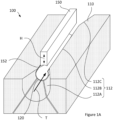
- Figure 1A shows a perspective view of a first reconfigurable wrapping mechanism 100.
- Figure 1B shows a cross-sectional view through the first reconfigurable wrapping mechanism 100 with a conveying belt 120 and the garniture bed 110 in an unworn condition.
- Figure 1C shows the first reconfigurable wrapping mechanism 100' after reconfiguration to compensate for wear of the conveying belt 120' and the garniture bed 110'.
- the reconfigurable wrapping mechanism 100 has a garniture bed 110 with a formation channel 112 extending along its length.
- a conveying belt 120 extends along the surface of the formation channel 112, and both are open along the length of the formation channel, with the open side facing towards an elongate shoe 150.
- the formation channel 112 has an inlet section 112A, a middle section 112B, and an outlet section 112C.
- the middle section 112B has a constant radius of curvature along its length.
- the inlet section 112A narrows-down, away from the inlet of the formation channel 112, and towards the middle section 112B.
- the outlet section 112C broadens-out, towards the outlet, and away from the middle section 112C.
- the conveying belt 120 may be an endless belt, and only part of the conveying belt is illustrated in Figure 1A , being the portion within the middle section 112B of the formation channel 112.
- a belt drive mechanism (not shown) is provided to drive the conveying belt 120 along the formation channel 112, in the transport direction T.
- the shoe 150 has a concave face 152, in cross-section perpendicular to the length of the formation channel 112, which faces towards the open side of the formation channel 112.
- the formation channel 112, conveying belt 120 and the concave face 152 of the shoe 150 are arranged and complementarily shaped for receiving a substantially cylindrical member, for example, a generally cylindrical core 160 wrapped within a wrapping paper 162.
- the elongate shoe 150 is optional, and may be omitted (for example, as shown in Figure 5 ).
- the garniture bed 110 is reconfigurable by re-sizing the formation channel 112.
- the garniture bed 110 is of a composite construction, having moveable garniture bed sub-members 110-1, 110-2 and 110-3, each providing part of the formation channel 212.
- the garniture bed sub-members 110-1, 110-2 and 110-3 may connect to a common support (not shown).
- the conveying belt 120 is in contact with the garniture bed sub-members 110-1, 110-2 and 110-3, and slides along them, in use.
- the garniture bed sub-members 110-1, 110-2 and 110-3 may each have a replaceable formation channel liner sub-member (not shown in Figures 1A-1C ) which is detachably connected to a complementary base sub-member, with the elongate formation channel being provided in the liner sub-members.
- the formation channel 112, conveying belt 120 and the concave face 152 of the shoe 150 are arranged and complementarily shaped for forming and transporting a substantially cylindrical member, entrained on the conveying belt, for example, a generally cylindrical core 160 wrapped within a wrapping paper 162.
- the belt drive mechanism drives the conveying belt 120 along the formation channel 112 in the transport direction T (indicated in Figure 1A ), the wrapping paper 162 is received onto and extends along the conveying belt 120, the core 160 is received onto the wrapping paper, and the wrapping paper is wrapped around the core.
- the wrapping paper 162 and the core 160 are progressively wrapped around the core, before the wrapped element (wrapped core) exits the formation channel along the outlet section 112C. Whilst passing along the formation channel 112 (for example, in the middle section 112B), the wrapping paper 162 is sealed around the core 160.
- the illustrated shoe 150 has a constant cross-sectional shape along its length, and extends along the middle section 112B of the formation channel 112.
- the shoe 150 may have a shape that varies along the length of the formation channel 112.
- the shoe 150 may extend part or all of the length of the inlet section 112A, part or all of the length of the middle section 112B, part or all of the length of the outlet section 112C, or may extend along part or all of a combination adjacent sections 112A, 112B, 112C of the formation channel 112.
- a double layered region 162D may pass along the concave surface 152 of the shoe 150 (or similarly, the double layered region 562B may pass along a concave surface of the formation channel 512, as shown in Figure 5 ).
- a contact adhesive may be provided between the layers in the double layered region 162D, and adhesion may be facilitated by contact between the double layered region and one or both of the conveying belt 120 and the formation channel 112.
- a thermosetting adhesive may be provided between the layers in the double layered region 162D.
- At least part of the concave surface 152 of the shoe 150 may be provided with a heating region (not shown) that heats the double layered region 162D to dry or melt an adhesive between the layers, and the concave surface 152 of the shoe 150 (or the surface of the formation channel 512, in the arrangement of Figure 5 ) may optionally also be provided with a cooling region (not shown) to cool the adhesive.
- the conveying belt 120 may be worn thinner, for example, being worn back to the dashed line indicated by 120W.
- the surface of the formation channel 112 may be worn away by the conveying belt 120, for example, being worn back to the dashed line indicated by 110W.
- the garniture bed sub-members 110-1', 110-2' and 110-3' may be moved inwardly (or outwardly) M-1, M-2 and M-3, to reconfigure the formation channel 112' to compensate for the wear.
- the shoe 150 may also move inwardly H to further compensate for wear.
- the garniture bed sub-members 110-1', 110-2' and 110-3' and the shoe 150 moves radially with respect to a central axis extending along the core 160.
- the garniture bed sub-members 110-1, 110-2 and 110-3, or both the conveying belt and the garniture bed sections may be used further, the garniture bed sub-members 110-1, 110-2 and 110-3 may be moved M-1, M-2 and M-3 inwardly to compensate for the worn conveying belt, for example, moving inwardly to provide a smaller diameter in the middle section 112B.
- the garniture bed sub-members 110-1, 110-2 and 110-3 may be moved M-1, M-2 and M-3 outwardly to compensate for the replacement of the worn conveying belt, for example, moving outwardly to provide a larger diameter in the middle section 112B.
- the height of the shoe 150 (where present) above the base of the formation channel 112 may be adjusted, H, in correspondence with reconfiguration of the garniture bed 110, and in correspondence with wear of the conveying belt 120.
- Reconfiguration of the garniture bed can enable continued use of one or both of a conveying belt and a garniture bed even when one or both have become worn, which may increase the time for which the wrapping mechanism may be run before it becomes necessary to replace the conveying belt or formation channel. Prolonging the running time of parts may increase operational efficiency and reduce operational costs.
- both the substantially cylindrical shape and the cross-sectional area of the wrapped core may be maintained within narrower tolerances.
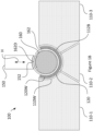
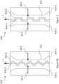
- Figure 2 shows a cross-sectional view through a second reconfigurable wrapping mechanism 200 in an unworn condition, which is generally similar to the first reconfigurable wrapping mechanism 100 of Figure 1A .
- the second reconfigurable wrapping mechanism 200 differs from the first reconfigurable wrapping mechanism 100 by the moveable garniture bed sub-members of the garniture bed 210 each being of a composite construction, having base sub-members 210A-1, 210A-2 and 210A-2 and replaceable formation channel liner sub-members 210B-1, 210B-2 and 210B-3, which are each detachably connected to a respective base sub-section, with the elongate formation channel 212 being provided by the assembly of formation channel liner sub-members.
- the formation channel 212, conveying belt 220 and the concave face 252 of the shoe 250 are arranged and complementarily shaped for forming and transporting a substantially cylindrical member, for example, a generally cylindrical core 260 wrapped within a wrapping paper 262, in a similar manner to the first reconfigurable wrapping mechanism 100, shown in Figures 1A to 1C .
- the conveying belt 220 may be worn thinner, for example, being worn back to the dashed line indicated by 220W.
- the surface of the formation channel 212 may be worn away by the conveying belt 220, for example, with the formation channel liner sub-members 210B-1, 210B-2 and 210B-2 being worn back to the dashed line indicated by 210W.
- the garniture bed base sub-members 210A-1, 210A-2 and 210A-3 may be moved inwardly to reconfigure the formation channel 212 to compensate for the wear.
- the shoe 250 may also move inwardly H to further compensate for wear.
- Reconfiguration of the garniture bed can enable continued use of one or both of a conveying belt and a garniture bed even when one or both have become worn, which may increase the time for which the wrapping mechanism may be run before it becomes necessary to replace the conveying belt or formation channel. Prolonging the running time of parts may increase operational efficiency and reduce operational costs.
- both the substantially cylindrical shape and the cross-sectional area of the wrapped core may be maintained within narrower tolerances.
- both the substantially cylindrical shape and the cross-sectional area of the wrapped core may be maintained within narrower tolerances.
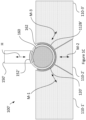
- Figure 3A shows a cross-sectional view through a third reconfigurable wrapping mechanism 300 in an unworn condition
- Figure 3B shows a plan view of the garniture bed 310 of Figure 3A .
- the wrapping mechanism 300 has a garniture bed 310 with a formation channel 312 extending along its length.
- a conveying belt 320 extends along the surface of the formation channel 312, and both are open along the length of the formation channel, with the open side facing towards an elongate shoe 350.
- the conveying belt 320 may be an endless belt.
- a belt drive mechanism (not shown) is provided to drive the conveying belt 320 along the formation channel 312, in the transport direction T.
- the shoe 350 has a concave face 352, in cross-section perpendicular to the length of the formation channel 312, which faces towards the open side of the formation channel 312.
- the formation channel 312, conveying belt 320 and the concave face 352 of the shoe 350 are arranged and complementarily shaped for forming a substantially cylindrically shaped wrapped rod, for example, a generally cylindrical core 360 wrapped within a wrapping paper 362.
- the third garniture bed 310 is of a composite construction, having moveable sub-members 310-1 and 310-2, each providing part of the formation channel 312.
- the garniture bed sub-members 310-1 and 310-2 may connect to a common support (not shown).
- the sub-members 310-1 and 310-2 may each have a replaceable formation channel liner sub-member (not shown) which is detachably connected to a complementary base sub-member, with the elongate formation channel being provided in the formation channel liner sub-members.
- the formation channel 312, conveying belt 320 and the concave face 352 of the shoe 350 are arranged and complementarily shaped for forming and transporting a substantially cylindrical member, for example, a generally cylindrical core 360 wrapped within a wrapping paper 362, in a similar manner to the first reconfigurable wrapping mechanism 100, shown in Figures 1A to 1C .
- the conveying belt 320 may be worn thinner, for example, being worn back to the dashed line indicated by 320W.
- the surface of the formation channel 312 may be worn away by the conveying belt 320, for example, being worn back to the dashed line indicated by 310W.
- the garniture bed sub-members 310-1 and 310-2 may be moved inwardly M-1 and M-2, to reconfigure the formation channel 312 to compensate for the wear.
- the shoe 450 may also move inwardly H to further compensate for wear.
- the moveable sub-members 310-1 and 310-2 are configured to move inwardly (or outwardly) and parallel to each other, and perpendicular to movement H of the shoe 350 (for example, each of the garniture bed sections 310-1, and 310-2 and the shoe 350 moves radially with respect to a central axis extending along the core 360).
- the moveable parts of the wrapping mechanism may alternatively be configured to move inwardly at different angles (for example, in a symmetrical arrangement).
- Reconfiguration of the garniture bed can enable continued use of one or both of a conveying belt and a garniture bed even when one or both have become worn, which may increase the time for which the wrapping mechanism may be run before it becomes necessary to replace the conveying belt or formation channel. Prolonging the running time of parts may increase operational efficiency and reduce operational costs.
- both the substantially cylindrical shape and the cross-sectional area of the wrapped core may be maintained within narrower tolerances.
- both the substantially cylindrical shape and the cross-sectional area of the wrapped core may be maintained within narrower tolerances.
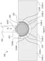
- the facing edges 314-1 and 314-2 of the garniture bed sub-members 310-1 and 310-2 has interdigitated arrangements of teeth, which permit the garniture bed sub-members to move inwardly (or outwardly).
- the teeth along the facing edges 314-1 and 314-2 remain interleaved, providing enhanced support for the conveying belt 320, web material and core.
- the facing edges may have complementary zig-zig shaped edges.
- the moveable sections 110-1, 110-2, 110-3, 210-1 and 210-2 of other reconfigurable wrapping mechanisms 100 and 200 are additionally be provided with interdigitated arrangements of teeth along their facing edges, at the formation channel surface 112, 212.
- Figure 4 shows a fourth composite garniture bed 410 having garniture bed sections 410-1 and 410-2 that is generally similar to the composite garniture bed 310 of Figures 3A and 3B .
- the garniture bed 410 of Figure 4 differs from the garniture bed 310 of Figures 3A and 3B by the interdigitated facing edges 414-1 and 414-2 having complementary castellated shapes.
- Formation channel assemblies 100, 200, 300, and 400 of Figures 1A to 4 have one, two or three sections that each provide part of the formation channel surface.
- the garniture bed may a larger number of sections that each provide part of the formation channel surface.
- the reconfigurable wrapping mechanisms 100, 200, and 300 illustrated in Figures 1A to 3A each comprise an elongate shoe 150, 250, and 350. However, alternatively, the elongate shoe may be omitted from the reconfigurable wrapping mechanisms.
- Figure 5 shows a cross-sectional view through a fifth reconfigurable wrapping mechanism 600 in an unworn condition, which is generally similar to the first reconfigurable wrapping mechanism 100 of Figures 1A to 1C .
- the fifth reconfigurable wrapping mechanism 500 differs from the first reconfigurable wrapping mechanism 100 by omitting the elongate shoe 150.
- the formation channel 512 and conveying belt 520 are shaped for forming and transporting a substantially cylindrical member, entrained on the conveying belt, for example, a generally cylindrical core 560 wrapped within a wrapping paper 562.
- the belt drive mechanism drives the conveying belt 520 along the formation channel 512 (for example, in the transport direction T, as indicated in Figure 1A ), the wrapping paper 562 is received onto and extends along the conveying belt 520, the core 560 is received onto the wrapping paper, and the wrapping paper is wrapped around the core.
- a double layered region 562D may pass along the concave surface of the formation channel 512.
- a contact adhesive may be provided between the layers in the double layered region 562D, and adhesion may be facilitated by contact between the double layered region and one or both of the conveying belt 520 and the formation channel 512.
- a thermosetting adhesive may be provided between the layers in the double layered region 562D.
- At least part of the concave surface of the formation channel 512 may be provided with a heating region (not shown) that heats the double layered region 562D to dry or melt the adhesive, and the formation channel 512 may optionally also be provided with a cooling region (not shown) to cool the double layered region.
- the conveying belt 520 may be worn thinner, for example, being worn back to the dashed line indicated by 520W.
- the replaceable formation channel liner 510B may be worn away by the conveying belts 520, for example, being worn back to the dashed line indicated by 510W.
- the garniture bed sub-members 510-1, 510-2 and 510-3 may be moved inwardly (or outwardly) M-1, M-2 and M-3, to reconfigure the formation channel 512 to compensate for the wear.
- the garniture bed sub-members 510-1, 510-2 and 510-3 move radially with respect to a central axis extending along the core 560.
- the garniture bed sub-members 510-1, 510-2 and 510-3, or both the conveying belt and the garniture bed sections is detected and the conveying belt may be used further, the garniture bed sub-members 510-1, 510-2 and 510-3 may be moved M-1, M-2 and M-3 inwardly to compensate for the worn conveying belt, for example, moving inwardly to provide a smaller diameter in the middle section 512B.
- the garniture bed sub-members 510-1, 510-2 and 510-3 may be moved M-1, M-2 and M-3 outwardly to compensate for the replacement of the worn conveying belt, for example, moving outwardly to provide a larger diameter in the middle section 512B.
- Reconfiguration of the garniture bed can enable continued use of one or both of a belt and a garniture bed even when one or both have become worn, which may increase the time for which the wrapping mechanism may be run before it becomes necessary to replace the belt or formation channel. Prolonging the running time of parts may increase operational efficiency and reduce operational costs.
- both the substantially cylindrical shape and the cross-sectional area of the wrapped core may be maintained within narrower tolerances.
Landscapes
- Paper (AREA)
- Belt Conveyors (AREA)
- Automotive Seat Belt Assembly (AREA)
- Manufacturing Of Cigar And Cigarette Tobacco (AREA)
- Containers And Plastic Fillers For Packaging (AREA)
Applications Claiming Priority (2)
| Application Number | Priority Date | Filing Date | Title |
|---|---|---|---|
| EP18187372 | 2018-08-03 | ||
| PCT/EP2019/070626 WO2020025671A1 (en) | 2018-08-03 | 2019-07-31 | Reconfigurable wrapping mechanism |
Publications (3)
| Publication Number | Publication Date |
|---|---|
| EP3829348A1 EP3829348A1 (en) | 2021-06-09 |
| EP3829348C0 EP3829348C0 (en) | 2024-07-31 |
| EP3829348B1 true EP3829348B1 (en) | 2024-07-31 |
Family
ID=63165210
Family Applications (1)
| Application Number | Title | Priority Date | Filing Date |
|---|---|---|---|
| EP19745160.2A Active EP3829348B1 (en) | 2018-08-03 | 2019-07-31 | Reconfigurable garniture |
Country Status (7)
| Country | Link |
|---|---|
| US (1) | US11690397B2 (pl) |
| EP (1) | EP3829348B1 (pl) |
| JP (1) | JP7444847B2 (pl) |
| KR (1) | KR102866920B1 (pl) |
| CN (1) | CN112437613B (pl) |
| PL (1) | PL3829348T3 (pl) |
| WO (1) | WO2020025671A1 (pl) |
Families Citing this family (1)
| Publication number | Priority date | Publication date | Assignee | Title |
|---|---|---|---|---|
| WO2021156816A1 (en) * | 2020-02-07 | 2021-08-12 | Sasib S.P.A. | Manufacturing machine and manufacturing method for the production of a tubular element, in particular for a smoking article |
Citations (1)
| Publication number | Priority date | Publication date | Assignee | Title |
|---|---|---|---|---|
| DE2836030C2 (de) * | 1977-08-24 | 1987-01-29 | Molins Ltd., London | Strangherstellungsmaschine für die tabakverarbeitende Industrie |
Family Cites Families (12)
| Publication number | Priority date | Publication date | Assignee | Title |
|---|---|---|---|---|
| GB574861A (en) * | 1944-07-18 | 1946-01-23 | William Isler | Improvements in or relating to garnitures for continuous-rod cigarette-making machines |
| GB8609482D0 (en) * | 1986-04-18 | 1986-05-21 | Imp Group Plc | Packaging arrangement |
| JP3273802B2 (ja) * | 1992-02-13 | 2002-04-15 | 日本たばこ産業株式会社 | シガレット製造機における巻たばこの巻径制御装置 |
| GB0324525D0 (en) * | 2003-10-21 | 2003-11-26 | British American Tobacco Co | Smoking articles and smokable filler material therefor |
| US20110271968A1 (en) * | 2010-05-07 | 2011-11-10 | Carolyn Rierson Carpenter | Filtered Cigarette With Modifiable Sensory Characteristics |
| DE102010051894A1 (de) * | 2010-11-22 | 2012-05-24 | Hauni Maschinenbau Ag | Formatsystem und Formatteile für eine Strangherstellmaschine der tabakverarbeitenden Industrie |
| US10064429B2 (en) * | 2011-09-23 | 2018-09-04 | R.J. Reynolds Tobacco Company | Mixed fiber product for use in the manufacture of cigarette filter elements and related methods, systems, and apparatuses |
| DE102012204442A1 (de) * | 2012-03-20 | 2013-09-26 | Hauni Maschinenbau Ag | Formateinrichtung einer Strangmaschine |
| DE102012208450B4 (de) * | 2012-05-21 | 2015-03-26 | Hauni Maschinenbau Ag | Strangformungsvorrichtung und Strangmaschine der Tabak verarbeitenden Industrie |
| EP3324760B1 (en) * | 2015-07-17 | 2021-05-05 | Altria Client Services LLC | Rod forming apparatus and method |
| RU2732956C2 (ru) * | 2015-10-08 | 2020-09-25 | Филип Моррис Продактс С.А. | Способ регулирования диаметра удлиненного стержня |
| DE102016121618A1 (de) * | 2016-11-11 | 2018-05-17 | Hauni Maschinenbau Gmbh | Strangherstellmaschine zur Herstellung von Produkten der Tabak verarbeitenden Industrie und zugehörige Formatgarnitur |
-
2019
- 2019-07-31 KR KR1020217002032A patent/KR102866920B1/ko active Active
- 2019-07-31 US US17/263,716 patent/US11690397B2/en active Active
- 2019-07-31 EP EP19745160.2A patent/EP3829348B1/en active Active
- 2019-07-31 JP JP2021503092A patent/JP7444847B2/ja active Active
- 2019-07-31 PL PL19745160.2T patent/PL3829348T3/pl unknown
- 2019-07-31 WO PCT/EP2019/070626 patent/WO2020025671A1/en not_active Ceased
- 2019-07-31 CN CN201980046606.XA patent/CN112437613B/zh active Active
Patent Citations (1)
| Publication number | Priority date | Publication date | Assignee | Title |
|---|---|---|---|---|
| DE2836030C2 (de) * | 1977-08-24 | 1987-01-29 | Molins Ltd., London | Strangherstellungsmaschine für die tabakverarbeitende Industrie |
Non-Patent Citations (1)
| Title |
|---|
| ANONYMOUS: "Segmentiertes Format", PRIOR ART JOURNAL, vol. 5, 8 March 2018 (2018-03-08), pages 42 - 43, XP055835335 * |
Also Published As
| Publication number | Publication date |
|---|---|
| CN112437613A (zh) | 2021-03-02 |
| EP3829348A1 (en) | 2021-06-09 |
| KR102866920B1 (ko) | 2025-10-13 |
| JP2021531770A (ja) | 2021-11-25 |
| PL3829348T3 (pl) | 2024-12-02 |
| EP3829348C0 (en) | 2024-07-31 |
| US20210368857A1 (en) | 2021-12-02 |
| BR112021001407A2 (pt) | 2021-04-27 |
| WO2020025671A1 (en) | 2020-02-06 |
| US11690397B2 (en) | 2023-07-04 |
| JP7444847B2 (ja) | 2024-03-06 |
| CN112437613B (zh) | 2023-07-25 |
| KR20210038880A (ko) | 2021-04-08 |
Similar Documents
| Publication | Publication Date | Title |
|---|---|---|
| EP3829349B1 (en) | Reconfigurable wrapping mechanism | |
| CN1112859C (zh) | 烟草加工工业中棒状制品的输送装置及其引导件 | |
| JP5017104B2 (ja) | 複合タバコフィルタの製造装置及び方法 | |
| EP3829348B1 (en) | Reconfigurable garniture | |
| RU2795760C2 (ru) | Реконфигурируемое оберточное устройство для формирования цилиндрического обернутого элемента, способ реконфигурирования ложа гарнитуры в оберточном устройстве и способ изготовления цилиндрического обернутого элемента с помощью оберточного устройства | |
| US10349620B2 (en) | Method for forming and cooling an initially hot and therefore flowable melted cheese | |
| RU2787987C2 (ru) | Способ реконфигурирования ложа гарнитуры в оберточном устройстве | |
| WO2020201682A1 (en) | Apparatus for manufacturing a rod of aerosolisable material and method of manufacturing a rod of aerosolisable material | |
| BR112021001407B1 (pt) | Mecanismo de embalagem reconfigurável, método de reconfiguração de um leito de guarnição em um mecanismo de embalagem e método de fabricação de um elemento embalado substancialmente cilíndrico com um mecanismo de embalagem | |
| BR112021001500B1 (pt) | Método de reconfiguração de um leito de guarnição | |
| JP4150475B2 (ja) | 食品材料の供給装置 | |
| NL8204767A (nl) | Werkwijze voor het vormen van gesneden tabaksreepjes en inrichting voor het vormen van gesneden tabak. | |
| EP4074193B1 (en) | Machine and method for producing a continuous rope of the tobacco industry | |
| JP3694257B2 (ja) | 連続した棒状食品の成形方法及び装置並びにコンベアベルト | |
| JP2005058232A (ja) | フィルタロッドを製造する方法と装置 | |
| JP4004327B2 (ja) | 食品材料の供給装置 | |
| WO2020201681A1 (en) | Apparatus for manufacturing a rod of aerosolisable material and method of manufacturing a rod of aerosolisable material | |
| US20230130205A1 (en) | Apparatus for making a sheet of material comprising vegetable and/or alkaloid substances |
Legal Events
| Date | Code | Title | Description |
|---|---|---|---|
| STAA | Information on the status of an ep patent application or granted ep patent |
Free format text: STATUS: UNKNOWN |
|
| STAA | Information on the status of an ep patent application or granted ep patent |
Free format text: STATUS: THE INTERNATIONAL PUBLICATION HAS BEEN MADE |
|
| PUAI | Public reference made under article 153(3) epc to a published international application that has entered the european phase |
Free format text: ORIGINAL CODE: 0009012 |
|
| STAA | Information on the status of an ep patent application or granted ep patent |
Free format text: STATUS: REQUEST FOR EXAMINATION WAS MADE |
|
| 17P | Request for examination filed |
Effective date: 20201216 |
|
| AK | Designated contracting states |
Kind code of ref document: A1 Designated state(s): AL AT BE BG CH CY CZ DE DK EE ES FI FR GB GR HR HU IE IS IT LI LT LU LV MC MK MT NL NO PL PT RO RS SE SI SK SM TR |
|
| TPAC | Observations filed by third parties |
Free format text: ORIGINAL CODE: EPIDOSNTIPA |
|
| DAV | Request for validation of the european patent (deleted) | ||
| DAX | Request for extension of the european patent (deleted) | ||
| STAA | Information on the status of an ep patent application or granted ep patent |
Free format text: STATUS: EXAMINATION IS IN PROGRESS |
|
| 17Q | First examination report despatched |
Effective date: 20220608 |
|
| GRAP | Despatch of communication of intention to grant a patent |
Free format text: ORIGINAL CODE: EPIDOSNIGR1 |
|
| STAA | Information on the status of an ep patent application or granted ep patent |
Free format text: STATUS: GRANT OF PATENT IS INTENDED |
|
| INTG | Intention to grant announced |
Effective date: 20240326 |
|
| GRAS | Grant fee paid |
Free format text: ORIGINAL CODE: EPIDOSNIGR3 |
|
| GRAA | (expected) grant |
Free format text: ORIGINAL CODE: 0009210 |
|
| STAA | Information on the status of an ep patent application or granted ep patent |
Free format text: STATUS: THE PATENT HAS BEEN GRANTED |
|
| AK | Designated contracting states |
Kind code of ref document: B1 Designated state(s): AL AT BE BG CH CY CZ DE DK EE ES FI FR GB GR HR HU IE IS IT LI LT LU LV MC MK MT NL NO PL PT RO RS SE SI SK SM TR |
|
| REG | Reference to a national code |
Ref country code: CH Ref legal event code: EP Ref country code: GB Ref legal event code: FG4D |
|
| REG | Reference to a national code |
Ref country code: DE Ref legal event code: R096 Ref document number: 602019056115 Country of ref document: DE |
|
| REG | Reference to a national code |
Ref country code: IE Ref legal event code: FG4D |
|
| U01 | Request for unitary effect filed |
Effective date: 20240731 |
|
| U07 | Unitary effect registered |
Designated state(s): AT BE BG DE DK EE FI FR IT LT LU LV MT NL PT RO SE SI Effective date: 20240902 |
|
| U20 | Renewal fee for the european patent with unitary effect paid |
Year of fee payment: 6 Effective date: 20240925 |
|
| PG25 | Lapsed in a contracting state [announced via postgrant information from national office to epo] |
Ref country code: NO Free format text: LAPSE BECAUSE OF FAILURE TO SUBMIT A TRANSLATION OF THE DESCRIPTION OR TO PAY THE FEE WITHIN THE PRESCRIBED TIME-LIMIT Effective date: 20241031 |
|
| PG25 | Lapsed in a contracting state [announced via postgrant information from national office to epo] |
Ref country code: GR Free format text: LAPSE BECAUSE OF FAILURE TO SUBMIT A TRANSLATION OF THE DESCRIPTION OR TO PAY THE FEE WITHIN THE PRESCRIBED TIME-LIMIT Effective date: 20241101 |
|
| PG25 | Lapsed in a contracting state [announced via postgrant information from national office to epo] |
Ref country code: IS Free format text: LAPSE BECAUSE OF FAILURE TO SUBMIT A TRANSLATION OF THE DESCRIPTION OR TO PAY THE FEE WITHIN THE PRESCRIBED TIME-LIMIT Effective date: 20241130 |
|
| PG25 | Lapsed in a contracting state [announced via postgrant information from national office to epo] |
Ref country code: HR Free format text: LAPSE BECAUSE OF FAILURE TO SUBMIT A TRANSLATION OF THE DESCRIPTION OR TO PAY THE FEE WITHIN THE PRESCRIBED TIME-LIMIT Effective date: 20240731 |
|
| PG25 | Lapsed in a contracting state [announced via postgrant information from national office to epo] |
Ref country code: RS Free format text: LAPSE BECAUSE OF FAILURE TO SUBMIT A TRANSLATION OF THE DESCRIPTION OR TO PAY THE FEE WITHIN THE PRESCRIBED TIME-LIMIT Effective date: 20241031 Ref country code: ES Free format text: LAPSE BECAUSE OF FAILURE TO SUBMIT A TRANSLATION OF THE DESCRIPTION OR TO PAY THE FEE WITHIN THE PRESCRIBED TIME-LIMIT Effective date: 20240731 |
|
| PG25 | Lapsed in a contracting state [announced via postgrant information from national office to epo] |
Ref country code: RS Free format text: LAPSE BECAUSE OF FAILURE TO SUBMIT A TRANSLATION OF THE DESCRIPTION OR TO PAY THE FEE WITHIN THE PRESCRIBED TIME-LIMIT Effective date: 20241031 Ref country code: NO Free format text: LAPSE BECAUSE OF FAILURE TO SUBMIT A TRANSLATION OF THE DESCRIPTION OR TO PAY THE FEE WITHIN THE PRESCRIBED TIME-LIMIT Effective date: 20241031 Ref country code: IS Free format text: LAPSE BECAUSE OF FAILURE TO SUBMIT A TRANSLATION OF THE DESCRIPTION OR TO PAY THE FEE WITHIN THE PRESCRIBED TIME-LIMIT Effective date: 20241130 Ref country code: HR Free format text: LAPSE BECAUSE OF FAILURE TO SUBMIT A TRANSLATION OF THE DESCRIPTION OR TO PAY THE FEE WITHIN THE PRESCRIBED TIME-LIMIT Effective date: 20240731 Ref country code: GR Free format text: LAPSE BECAUSE OF FAILURE TO SUBMIT A TRANSLATION OF THE DESCRIPTION OR TO PAY THE FEE WITHIN THE PRESCRIBED TIME-LIMIT Effective date: 20241101 Ref country code: ES Free format text: LAPSE BECAUSE OF FAILURE TO SUBMIT A TRANSLATION OF THE DESCRIPTION OR TO PAY THE FEE WITHIN THE PRESCRIBED TIME-LIMIT Effective date: 20240731 |
|
| PG25 | Lapsed in a contracting state [announced via postgrant information from national office to epo] |
Ref country code: SM Free format text: LAPSE BECAUSE OF FAILURE TO SUBMIT A TRANSLATION OF THE DESCRIPTION OR TO PAY THE FEE WITHIN THE PRESCRIBED TIME-LIMIT Effective date: 20240731 |
|
| PG25 | Lapsed in a contracting state [announced via postgrant information from national office to epo] |
Ref country code: MC Free format text: LAPSE BECAUSE OF FAILURE TO SUBMIT A TRANSLATION OF THE DESCRIPTION OR TO PAY THE FEE WITHIN THE PRESCRIBED TIME-LIMIT Effective date: 20240731 |
|
| PG25 | Lapsed in a contracting state [announced via postgrant information from national office to epo] |
Ref country code: CZ Free format text: LAPSE BECAUSE OF FAILURE TO SUBMIT A TRANSLATION OF THE DESCRIPTION OR TO PAY THE FEE WITHIN THE PRESCRIBED TIME-LIMIT Effective date: 20240731 |
|
| PG25 | Lapsed in a contracting state [announced via postgrant information from national office to epo] |
Ref country code: SK Free format text: LAPSE BECAUSE OF FAILURE TO SUBMIT A TRANSLATION OF THE DESCRIPTION OR TO PAY THE FEE WITHIN THE PRESCRIBED TIME-LIMIT Effective date: 20240731 |
|
| PLBE | No opposition filed within time limit |
Free format text: ORIGINAL CODE: 0009261 |
|
| STAA | Information on the status of an ep patent application or granted ep patent |
Free format text: STATUS: NO OPPOSITION FILED WITHIN TIME LIMIT |
|
| 26N | No opposition filed |
Effective date: 20250501 |
|
| PG25 | Lapsed in a contracting state [announced via postgrant information from national office to epo] |
Ref country code: IE Free format text: LAPSE BECAUSE OF NON-PAYMENT OF DUE FEES Effective date: 20240731 |
|
| U20 | Renewal fee for the european patent with unitary effect paid |
Year of fee payment: 7 Effective date: 20250728 |
|
| PGFP | Annual fee paid to national office [announced via postgrant information from national office to epo] |
Ref country code: PL Payment date: 20250730 Year of fee payment: 7 |
|
| PGFP | Annual fee paid to national office [announced via postgrant information from national office to epo] |
Ref country code: GB Payment date: 20250722 Year of fee payment: 7 |
|
| PGFP | Annual fee paid to national office [announced via postgrant information from national office to epo] |
Ref country code: CH Payment date: 20250801 Year of fee payment: 7 |