EP3828463B1 - Lampe und entsprechendes verfahren - Google Patents
Lampe und entsprechendes verfahren Download PDFInfo
- Publication number
- EP3828463B1 EP3828463B1 EP20206465.5A EP20206465A EP3828463B1 EP 3828463 B1 EP3828463 B1 EP 3828463B1 EP 20206465 A EP20206465 A EP 20206465A EP 3828463 B1 EP3828463 B1 EP 3828463B1
- Authority
- EP
- European Patent Office
- Prior art keywords
- lamp
- air
- lamp body
- base portion
- rear base
- Prior art date
- Legal status (The legal status is an assumption and is not a legal conclusion. Google has not performed a legal analysis and makes no representation as to the accuracy of the status listed.)
- Active
Links
Images


Classifications
-
- F—MECHANICAL ENGINEERING; LIGHTING; HEATING; WEAPONS; BLASTING
- F21—LIGHTING
- F21K—NON-ELECTRIC LIGHT SOURCES USING LUMINESCENCE; LIGHT SOURCES USING ELECTROCHEMILUMINESCENCE; LIGHT SOURCES USING CHARGES OF COMBUSTIBLE MATERIAL; LIGHT SOURCES USING SEMICONDUCTOR DEVICES AS LIGHT-GENERATING ELEMENTS; LIGHT SOURCES NOT OTHERWISE PROVIDED FOR
- F21K9/00—Light sources using semiconductor devices as light-generating elements, e.g. using light-emitting diodes [LED] or lasers
- F21K9/20—Light sources comprising attachment means
- F21K9/23—Retrofit light sources for lighting devices with a single fitting for each light source, e.g. for substitution of incandescent lamps with bayonet or threaded fittings
-
- F—MECHANICAL ENGINEERING; LIGHTING; HEATING; WEAPONS; BLASTING
- F21—LIGHTING
- F21S—NON-PORTABLE LIGHTING DEVICES; SYSTEMS THEREOF; VEHICLE LIGHTING DEVICES SPECIALLY ADAPTED FOR VEHICLE EXTERIORS
- F21S41/00—Illuminating devices specially adapted for vehicle exteriors, e.g. headlamps
- F21S41/10—Illuminating devices specially adapted for vehicle exteriors, e.g. headlamps characterised by the light source
- F21S41/14—Illuminating devices specially adapted for vehicle exteriors, e.g. headlamps characterised by the light source characterised by the type of light source
- F21S41/141—Light emitting diodes [LED]
- F21S41/147—Light emitting diodes [LED] the main emission direction of the LED being angled to the optical axis of the illuminating device
- F21S41/148—Light emitting diodes [LED] the main emission direction of the LED being angled to the optical axis of the illuminating device the main emission direction of the LED being perpendicular to the optical axis
-
- F—MECHANICAL ENGINEERING; LIGHTING; HEATING; WEAPONS; BLASTING
- F21—LIGHTING
- F21S—NON-PORTABLE LIGHTING DEVICES; SYSTEMS THEREOF; VEHICLE LIGHTING DEVICES SPECIALLY ADAPTED FOR VEHICLE EXTERIORS
- F21S41/00—Illuminating devices specially adapted for vehicle exteriors, e.g. headlamps
- F21S41/10—Illuminating devices specially adapted for vehicle exteriors, e.g. headlamps characterised by the light source
- F21S41/19—Attachment of light sources or lamp holders
- F21S41/192—Details of lamp holders, terminals or connectors
-
- F—MECHANICAL ENGINEERING; LIGHTING; HEATING; WEAPONS; BLASTING
- F21—LIGHTING
- F21S—NON-PORTABLE LIGHTING DEVICES; SYSTEMS THEREOF; VEHICLE LIGHTING DEVICES SPECIALLY ADAPTED FOR VEHICLE EXTERIORS
- F21S45/00—Arrangements within vehicle lighting devices specially adapted for vehicle exteriors, for purposes other than emission or distribution of light
- F21S45/40—Cooling of lighting devices
- F21S45/42—Forced cooling
- F21S45/43—Forced cooling using gas
-
- F—MECHANICAL ENGINEERING; LIGHTING; HEATING; WEAPONS; BLASTING
- F21—LIGHTING
- F21V—FUNCTIONAL FEATURES OR DETAILS OF LIGHTING DEVICES OR SYSTEMS THEREOF; STRUCTURAL COMBINATIONS OF LIGHTING DEVICES WITH OTHER ARTICLES, NOT OTHERWISE PROVIDED FOR
- F21V29/00—Protecting lighting devices from thermal damage; Cooling or heating arrangements specially adapted for lighting devices or systems
- F21V29/50—Cooling arrangements
- F21V29/502—Cooling arrangements characterised by the adaptation for cooling of specific components
- F21V29/508—Cooling arrangements characterised by the adaptation for cooling of specific components of electrical circuits
-
- F—MECHANICAL ENGINEERING; LIGHTING; HEATING; WEAPONS; BLASTING
- F21—LIGHTING
- F21V—FUNCTIONAL FEATURES OR DETAILS OF LIGHTING DEVICES OR SYSTEMS THEREOF; STRUCTURAL COMBINATIONS OF LIGHTING DEVICES WITH OTHER ARTICLES, NOT OTHERWISE PROVIDED FOR
- F21V29/00—Protecting lighting devices from thermal damage; Cooling or heating arrangements specially adapted for lighting devices or systems
- F21V29/50—Cooling arrangements
- F21V29/60—Cooling arrangements characterised by the use of a forced flow of gas, e.g. air
-
- F—MECHANICAL ENGINEERING; LIGHTING; HEATING; WEAPONS; BLASTING
- F21—LIGHTING
- F21V—FUNCTIONAL FEATURES OR DETAILS OF LIGHTING DEVICES OR SYSTEMS THEREOF; STRUCTURAL COMBINATIONS OF LIGHTING DEVICES WITH OTHER ARTICLES, NOT OTHERWISE PROVIDED FOR
- F21V29/00—Protecting lighting devices from thermal damage; Cooling or heating arrangements specially adapted for lighting devices or systems
- F21V29/50—Cooling arrangements
- F21V29/70—Cooling arrangements characterised by passive heat-dissipating elements, e.g. heat-sinks
- F21V29/83—Cooling arrangements characterised by passive heat-dissipating elements, e.g. heat-sinks the elements having apertures, ducts or channels, e.g. heat radiation holes
-
- F—MECHANICAL ENGINEERING; LIGHTING; HEATING; WEAPONS; BLASTING
- F21—LIGHTING
- F21Y—INDEXING SCHEME ASSOCIATED WITH SUBCLASSES F21K, F21L, F21S and F21V, RELATING TO THE FORM OR THE KIND OF THE LIGHT SOURCES OR OF THE COLOUR OF THE LIGHT EMITTED
- F21Y2103/00—Elongate light sources, e.g. fluorescent tubes
- F21Y2103/10—Elongate light sources, e.g. fluorescent tubes comprising a linear array of point-like light-generating elements
-
- F—MECHANICAL ENGINEERING; LIGHTING; HEATING; WEAPONS; BLASTING
- F21—LIGHTING
- F21Y—INDEXING SCHEME ASSOCIATED WITH SUBCLASSES F21K, F21L, F21S and F21V, RELATING TO THE FORM OR THE KIND OF THE LIGHT SOURCES OR OF THE COLOUR OF THE LIGHT EMITTED
- F21Y2107/00—Light sources with three-dimensionally disposed light-generating elements
- F21Y2107/30—Light sources with three-dimensionally disposed light-generating elements on the outer surface of cylindrical surfaces, e.g. rod-shaped supports having a circular or a polygonal cross section
-
- F—MECHANICAL ENGINEERING; LIGHTING; HEATING; WEAPONS; BLASTING
- F21—LIGHTING
- F21Y—INDEXING SCHEME ASSOCIATED WITH SUBCLASSES F21K, F21L, F21S and F21V, RELATING TO THE FORM OR THE KIND OF THE LIGHT SOURCES OR OF THE COLOUR OF THE LIGHT EMITTED
- F21Y2115/00—Light-generating elements of semiconductor light sources
- F21Y2115/10—Light-emitting diodes [LED]
Definitions
- One or more embodiments may be applied to lamps employing solid-state light generators, e.g. LED light generators.
- One or more embodiments may advantageously be employed in the automotive sector, e.g. as automotive retrofit lamps.
- Lamps employing solid-state, e.g. LED, light generators, are increasingly replacing conventional filament and fluorescent lamps.
- Automotive LED lamps are adapted to provide flux and light distribution characteristics which are compatible with the usage requirements of automotive lamps, wherein the characteristics of intensity and distribution of the luminous flux are particularly important.
- This aspect is particularly meaningful in the automotive sector, e.g. in the implementation of H-type LED lamps which may be used in the place of conventional, e.g. halogen, lamps. This applies both to retrofit and (as the case may be) to first installation applications.
- the state of the art comprises various documents disclosing LED lamps having forced ventilation mechanisms, such as e.g. US Patents 9,677,753 (Briedenassel ); 10,415,787 (Lessard ); 9,470,391 (Itagaki - to which US 2014/328079 A1 corresponds); 8,118,462 (Inoue ); 8,066,414 (Pabst ); 7,144,140 (Sun ); as well as the US Patent Application Publications such as US2015/0146447 (Kuepper ); 2011/0025211 (Bae ); 2010/0165632 (Liang ); and 2010/0027270 (Huang ).
- Document CN 109 140 373 A discloses an automotive lamp comprising a heat-conductive mounting plate, a heat-conductive pipe sleeve, a control circuit board, two lamp panels and a heat dissipating fan.
- the two lamp panels are mounted on two side surfaces of the heat-conductive mounting plate with LEDs are arranged on the lamp panels.
- the end parts of the lamp panels pass through corresponding ventilating ports and extend into the heat-conductive pipe sleeve.
- the heat dissipating fan is used for blowing air into the heat-conductive pipe sleeve and then blowing the air to the lamp panels through the corresponding ventilating ports.
- Document CN 106 594 627 A taken as a model for the preamble claim 1, discloses an automotive light comprising a metal heat pipe with a light source installation section and a heat conduction section, LED light sources arranged on the light source installation section, and a heat radiator comprising a metal radiator and a thermal conductive plastic isolator, wherein the metal radiator and the heat conduction section form thermal connection; and the thermal conductive plastic isolator covers the heat conduction section so as to separate the heat conduction section from outside air.
- Document CN 207 334 634 U provides a similar disclosure of a car headlight comprising a radiator and a radiator fan.
- the radiator fan is installed to the opposite side of copper base plate.
- One or more embodiments aim at providing improved solutions, adapted to be employed with proper performances in various possible usage scenarios.
- said object may be achieved thanks to a lamp having the features specifically set forth in claim 1 that follows.
- One or more embodiments may refer to a corresponding method as per claim 9.
- One or more embodiments facilitate achieving a high compatibility (virtually as high as 100%) with conventional halogen lamps, while meeting specifications such as ECE regulations.
- achieving such results may be facilitated by the presence of an air-moving device (a blower or fan, for example) arranged centrally with respect to the lamp.
- an air-moving device a blower or fan, for example
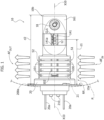
- reference number 10 denotes as a whole a lamp adapted to be used, for example, for the first installation or the retrofit of a light (e.g. a projector) of a vehicle such as a passenger car.
- Figure 1 shows a part of a reflector P of one of the lights (e.g. a headlamp) of such vehicle, which is not visible in its entirety in the figures.
- the lamp 10 may be, for example (and as already stated in the foregoing), a solid-state automotive lamp which may be used e.g. as a retrofit lamp, replacing an equivalent conventional lamp of the H-type, such as a halogen lamp.
- the lamp 10 may include a lamp body of elongated shape, whereon there are mounted, on opposed sides of the body itself, solid-state light sources.
- said sources comprise two linear arrays of (e.g. three) LEDs 141, 142, which extend in the direction of a longitudinal axis X10 of lamp 10.
- a mounting element 20 having e.g. the shape of a flanged cup, is adapted to mount lamp 10 onto a support body P, e.g. a reflector of an automotive lamp.
- the mounting solution illustrated herein is however only one of the possible mounting solutions of lamp 10 on such a support body, such as a reflector of an automotive lamp, e.g. having coupling mechanisms substantially similar to a bayonet coupling ("quarter-turn" mechanisms).
- the presently illustrated ring member 20 is a general example of an element configured for mounting the lamp on a vehicle, said element comprising, at the rear portion of the lamp body, at least one reference formation (such as an annular flange 200a) which is adapted to define a reference plane (denoted as RP in Figure 1 ) transverse to the longitudinal axis X10.
- at least one reference formation such as an annular flange 200a
- RP in Figure 1 a reference plane transverse to the longitudinal axis X10.
- lamp 10 may comprise, in the direction of longitudinal axis X10:
- the lamp body 10 may comprise a laminar element 12 (having features similar to a Printed Circuit Board, PCB) having two mutually opposed surfaces whereon there are arranged the LED light generators 141, 142.
- a laminar element 12 having features similar to a Printed Circuit Board, PCB having two mutually opposed surfaces whereon there are arranged the LED light generators 141, 142.
- the laminar element 12 may be interposed between two complementary parts, e.g. complementary shells, 161, 162, of a printed (metal or plastic) material.
- the parts 161, 162 with the laminar element 12 arranged therebetween may be kept together:
- the arrangement of the LED light generators 141, 142 on the surfaces of laminar element 12 is therefore such that generators 141, 142 project light away from the laminar element 12 in a generally radial direction with respect to axis X10.
- Parts 161, 162 are therefore provided, at the LED light generators 141, 142, with light-permeable portions, such as e.g. transparent openings or portions.
- Such transparent openings or portions are located at the bottom of two cavities 221, 222 which, in the assembled lamp body, form two (mirror) symmetrical recesses with respect to an ideal diametral plane of the lamp body.
- Such diametral plan substantially coincides with the lying plane of laminar element 12.
- the lamp body i.e. the elements 12, 161 and 162 and the mounting element 20
- the lamp body are engageable with each other, with the possibility of mounting lamp 10 on the support body P (see Figure 1 ) with said diametral plane, i.e. with laminar element 12, oriented in a vertical direction, in the plane of the drawing of Figure 1 .
- Axis X10 is oriented in an at least approximately horizontal direction.
- the LED light generators 141, 142 may be arranged substantially at the front (distal) portion 10b of lamp 10.
- the LED light generators 141, 142 may be supplied, in a manner known in itself, by a circuitry 21 housed in the rear portion 10a of lamp 10, via electrical lines or tracks 141a, 142a provided on laminar element 12.
- Circuitry 21 is in turn connected (e.g. via two electrical contact pins 210, adapted to extend through respective openings in the bottom wall of mounting element 20) to e.g. laminar contacts 20a, which are adapted to provide a hot and a ground contact for light generators 141, 142.
- one or more embodiments may envisage to impart, to the rear portion 10a of lamp 10 which hosts circuitry 21, an apertured (so to say cage-like) structure, having elongated, loophole-like apertures which are adapted to define an inlet 100 and an outlet 101 of ventilation air through the rear base portion 10a of the lamp body.
- an apertured (so to say cage-like) structure having elongated, loophole-like apertures which are adapted to define an inlet 100 and an outlet 101 of ventilation air through the rear base portion 10a of the lamp body.
- said openings may be arranged in two arrays of arch-shaped slots, which are located on opposed side with respect to the ideal diametral plane discussed in the foregoing, which passes through laminar element 12, by providing e.g. one array in part 161 and the other array in part 162.
- said two arrays or arch-shaped apertures may be mirror symmetrical with respect to said diametral plane.
- the lamp body (e.g. parts 161, 162 in the lamp 10 as exemplified herein) may have, at least at the rear portion 10a, a cross section (with reference to longitudinal axis X10) which is at least approximately circular, optionally wider than the cross section of front portion 10b.
- the apertures (loopholes) defining the inlet 100 and the outlet 101 of ventilation air may have a arch-like shape, i.e. a C shape, which extends along rounded (e.g. circular) paths lying in transverse planes with respect to axis X10, optionally along paths which are orthogonal and/or centered with respect to axis X10.
- the apertures may thus define ventilation air flow paths CA through the rear portion 10a of lamp 10.
- Such ventilation air by passing through the lamp body along a generally transverse (diametral) path from inlet 100 to outlet 101, is adapted to impinge on circuitry 21 as well, with the effect of removing heat therefrom.
- One or more embodiments may envisage that the heat developed by solid-state light generators 141, 142 during operation may be at least partly transferred towards the rear base portion 10a of lamp 10, by taking advantage of the thermal conductivity of laminar element 12 (PCB), of spacers 171, 172 (if present) and of parts 161, 162.
- PCB laminar element 12
- Such elements, and particularly parts 161, 162 are adapted to be made, in a way known in itself, of a metal or plastic (e.g. printed) material having good heat transfer properties.
- the heat developed by the solid-state light generators 141, 142 during operation may be at least partially dissipated thanks to an air ventilation flow, schematically shown by arrows AF IN , AF OUT in Figure 1 , which passes through the rear portion 10a of lamp 10 entering (AF IN ) through air inlet 100, on a first side S1, and exiting (AF OUT ) from air outlet 101, on a second side S2 (diametrically opposed to first side S1), in a generally transverse direction with respect to the transverse direction defined by axis X10.
- an air ventilation flow schematically shown by arrows AF IN , AF OUT in Figure 1 , which passes through the rear portion 10a of lamp 10 entering (AF IN ) through air inlet 100, on a first side S1, and exiting (AF OUT ) from air outlet 101, on a second side S2 (diametrically opposed to first side S1), in a generally transverse direction with respect to the transverse direction defined by axis X
- the ventilation air flow AF IN , AF OUT takes place therefore in a generally vertical direction, from the bottom to the top, with reference to the viewpoints of Figures 1 and 2 .
- air flow (an essentially convective flow) may advantageously be a forced flow, thanks to an air-moving element 102 (a blower such as a fan, for example) mounted on the rear portion 10a of lamp 10.
- air-moving element 102 a blower such as a fan, for example
- the air-moving element 102 may be arranged at a central position, i.e. at least approximately at axis X10.
- the air-moving element 102 may be mounted on one of the faces of the laminar support member 12.
- the air-moving element may be for example a component such as MagLev Motor Fan, Model UFF3-700, available from Sunonwealth Electric Machine Industry Co., Ltd. of Kaohsiung City, Taiwan (sunon.com), or such as TK FAN DA1504L05S available from Shenzen Tenkai Group Limited of Shenzen, China (tkfan.com).
- the air-moving element 102 may be electrically supplied by the same circuitry the heat whereof is dissipated by element 102, the latter being optionally mounted on said circuitry.
- air inlet 100 and air outlet 101 are located at a common longitudinal position (i.e. "at the same height", or at the same distance from reference plane RF) in the longitudinal direction of lamp 10 identified by axis X10, and the air-moving element 102 is positioned longitudinally in register with air inlet 100 and air oulet 101, i.e. at the same height of air inlet 100 and air outlet 101, always with reference to said longitudinal direction.
- the air-moving element 102 is positioned in the rear base portion 10a of the lamp body between a proximal end of the rear base portion 10a, i.e. the end located remote from the light sources 141, 142 (where, as visible in the figures, the mounting element 20 is located configured to mount the lamp 10 on a vehicle P) and a distal end of the same rear base portion 10a, i.e. the end facing towards the light sources 141, 142.
- Such a central arrangement of element 102 causes the air flow AF IN , AF OUT between air inlet 100 and air outlet 101 to encounter fewer obstacles, so that it may move with higher freedom and efficiency compared to a side arrangement of element 102 (e.g. at the bottom in Figure 1 ).
- This may optionally enable (e.g. in applications which are not particularly critical) to avoid a vertical mounting condition, as exemplified in Figure 1 , e.g. by providing a (forced) air flow AF IN , AF OUT in an at least approximately horizontal direction.
- FIG. 3 in the annexed drawings is taken from the ECE Regulations which impose the specifications for lamps to be used in the automotive sector, and specifically from a text known as Addendum 36: Regulation No. 37, pages 35-38 , which lists the dimensional parameters relevant for H7 lamps, which must be met in a LED lamp adapted to be used as a retrofit for an H7 incandescent lamp. Said ECE text for H7 lamps corresponds to the US Specifications SAE 9004 or 9007.
- One or more embodiments enable the implementation of LED lamps which, once energized, are adapted to emit at least 1200 lumen, while having the dimensions specified in the ECE Regulations, as shown in the annexed Figure.
- the white space in the Figure represents the spatial envelope wherein the (LED) retrofit lamp must be insertable together with its components.
- two meaningful dimensional data may consist: in the distance (currently denoted as Light Center Length, LCL) of 25 mm from the reference plane RP to the center CLS of the light source, as measured in an axial direction with respect to the lamp, i.e. on the reference axis; and in the (maximum) length of the lamp, amounting to 44 mm, as measured from the reference plane RP.
- LCL Light Center Length
- One or more embodiments are adapted to properly dissipate the heat deriving from the generation, by LED sources such as sources 141, 142, of 1200 lumen, while being compatible with the dimensions specified by the ECE Regulations.
- Figure 1 highlights that:
- simulation values referred to a luminous flus of 1222 lm with a supply current of 700 mA, with LED sources mounted onto a PCB support (MC) show temperature values Ts of the solid-state sources amounting to 130°C, and temperature values of the associated electronic components approximately amounting to 105/115°C.
- the air inlet and the air outlet may be located at a common longitudinal position in said longitudinal direction, and the air-moving element is positioned longitudinally in register with the air inlet and the air outlet in said longitudinal direction.
- the air-moving element is located in the rear base portion of the lamp body between a proximal end of the rear base portion, in a position remote from the solid-state light sources (where, as visible in the figures, the mounting element 20 is located) and a distal end of the rear base portion, adjacent the solid-state light sources.
- said ventilation apertures may comprise arch-shaped slots in the lamp body.
- the lamp body may comprise a thermally conductive material (e.g. in the portions or parts 161, 162, 12), which facilitates heat transfer from said solid-state light sources at the front portion of the lamp body towards said air-moving element (102) in the rear base portion of the lamp body.
- a thermally conductive material e.g. in the portions or parts 161, 162, 12
- a lamp as exemplified herein may fit a spatial envelope according to Figure 2 of Addendum 36 of ECE Regulation 37 for H7 lamps (SAE 9004 or 9007, in the United States).
- said solid-state light sources may comprise LED light sources.
- said solid-state light sources when energized, may emit a luminous flux of at least 1200 lm.
- a method of using a lamp as exemplified herein may comprise:
Landscapes
- Engineering & Computer Science (AREA)
- General Engineering & Computer Science (AREA)
- Physics & Mathematics (AREA)
- Microelectronics & Electronic Packaging (AREA)
- Optics & Photonics (AREA)
- Non-Portable Lighting Devices Or Systems Thereof (AREA)
- Arrangement Of Elements, Cooling, Sealing, Or The Like Of Lighting Devices (AREA)
Claims (9)
- Fahrzeugfestkörperlampe (10) für ein Fahrzeug, umfassend:einen Lampenkörper (12, 161, 162, 20), der sich in einer Längsrichtung (X10) erstreckt, wobei der Lampenkörper einen hinteren Basisabschnitt (10a) und einen vorderen Abschnitt (10b) aufweist und ein Stützelement (12) beinhaltet,Festkörperlichtquellen (141, 142), die an dem Stützelement (12) an dem vorderen Abschnitt (10b) des Lampenkörpers (12, 161, 162, 20) angeordnet sind,Ansteuerschaltung (21) der Lichtquellen (141, 142), die an dem hinteren Basisabschnitt (10a) des Lampenkörpers (12, 161, 162, 20) angeordnet ist,wobei:der hintere Basisabschnitt (10a) des Lampenkörpers (12, 161, 162, 20) Belüftungsöffnungen (100, 101) umfasst, die konfiguriert sind, um einen Strömungsweg für Belüftungsluft der Ansteuerschaltung (21) durch den hinteren Basisabschnitt (10a) des Lampenkörpers (12, 161, 162, 20) zwischen einander gegenüberliegenden ersten (S1) und zweiten (S2) Seiten des hinteren Basisabschnitts (10a) des Lampenkörpers (12, 161, 162, 20) bereitzustellen, wobei sich der Belüftungsluftströmungsweg von einem Lufteinlass (100) zu einem Luftauslass (101) quer zu der Längsrichtung (X10) erstreckt,ein Luftbewegungselement (102) an dem Stützelement (12) in dem hinteren Basisabschnitt (10a) des Lampenkörpers (12, 161, 162, 20) angeordnet bereitgestellt ist, wobei sich das Luftbewegungselement (102) in dem Luftströmungsweg zwischen dem Lufteinlass (100) und dem Luftauslass (101) befindet,das Luftbewegungselement (102) aktivierbar ist, um einen Luftstrom (AFIN, AFOUT) von der ersten Seite (S1) zu der zweiten Seite (S2) des hinteren Abschnitts (10a) des Lampenkörpers (12, 161, 162, 20) zu erzeugen,wobei:die Lampe ein Montageelement (20) umfasst, das konfiguriert ist, um die Lampe (10) an einem Fahrzeug (P) zu montieren, wobei sich das Montageelement (20) an einem proximalen Ende des hinteren Basisabschnitts (10a) entfernt von den Festkörperlichtquellen (141, 142) befindet, unddas Luftbewegungselement (102) sich in dem hinteren Basisabschnitt (10a) des Lampenkörpers (12, 161, 162, 20) zwischen einem proximalen Ende des hinteren Basisabschnitts (10a) entfernt von den Festkörperlichtquellen (141, 142) und einem distalen Ende des hinteren Basisabschnitts (10a) benachbart zu den Festkörperlichtquellen (141, 142) befindet,dadurch gekennzeichnet, dass:das Montageelement (20) an dem hinteren Basisabschnitt (10a) des Lampenkörpers (12, 161, 162, 20) mindestens eine Referenzformation (200a) umfasst, die eine Referenzebene (RP) quer zu der Längsrichtung (X10) definiert, unddie Festkörperlichtquellen (141, 142) an dem Stützelement (12) mit einer Mitte (CLS) der Festkörperlichtquellen (141, 142) in einem Abstand (d1) von ungefähr 25 mm von der Referenzebene (RP) angeordnet sind.
- Lampe (10) nach Anspruch 1, wobei sich der Lufteinlass (100) und der Luftauslass (101) an einer gemeinsamen Längsposition in der Längsrichtung (X10) befinden und das Luftbewegungselement (102) in Längsrichtung in Ausrichtung mit dem Lufteinlass (100) und dem Luftauslass (101) in der Längsrichtung (X10) positioniert ist.
- Lampe (10) nach Anspruch 1 oder Anspruch 2, wobei die Lüftungsöffnungen (100, 101) bogenförmige Schlitze in dem Lampenkörper (161, 162) umfassen.
- Lampe (10) nach einem der vorhergehenden Ansprüche, wobei der Lampenkörper wärmeleitendes Material (161, 162, 12) umfasst, das eine Wärmeübertragung von den Festkörperlichtquellen (141, 142) an dem vorderen Abschnitt (10b) des Lampenkörpers (12, 161, 162, 20) zu dem Luftbewegungselement (102) erleichtert, das in dem hinteren Basisabschnitt (10a) des Lampenkörpers bereitgestellt ist.
- Lampe (10) nach einem der vorhergehenden Ansprüche, wobei
die Länge (d2) der Lampe (10) zwischen der Referenzebene (RP) und dem Ende des vorderen Abschnitts (10b) weniger als 44 mm beträgt. - Lampe (10) nach einem der vorhergehenden Ansprüche, wobei die Lampe in eine räumliche Hülle gemäß Figur 2 von Anhang 36 der ECE-Vorschrift 37 für H7-Lampen (SAE 9004 oder 9007) passt.
- Lampe (10) nach einem der vorhergehenden Ansprüche, wobei die Festkörperlichtquellen LED-Lichtquellen (141, 142) umfassen.
- Lampe (10) nach einem der vorhergehenden Ansprüche, wobei die Festkörperlichtquellen (141, 142), wenn sie mit Energie versorgt werden, einen Lichtstrom von mindestens 1200 lm emittieren.
- Verfahren zum Verwenden der Lampe (10) nach einem der vorhergehenden Ansprüche, wobei das Verfahren umfasst:Montieren (20) der Lampe (10) an einem Fahrzeug (P), wobei die erste Seite (S1) und die zweite Seite (S2) des hinteren Basisabschnitts (10a) des Lampenkörpers (12, 161, 162, 20) jeweils nach unten und nach oben weisen,Aktivieren des Luftbewegungselements (102), um einen Luftstrom (AFIN, AFOUT) von der ersten Seite (S1) zu der zweiten Seite (S2) des hinteren Abschnitts (10a) des Lampenkörpers (12, 161, 162, 20) zu erzeugen.
Applications Claiming Priority (1)
| Application Number | Priority Date | Filing Date | Title |
|---|---|---|---|
| IT102019000022209A IT201900022209A1 (it) | 2019-11-26 | 2019-11-26 | Lampada e procedimento corrispondente |
Publications (2)
| Publication Number | Publication Date |
|---|---|
| EP3828463A1 EP3828463A1 (de) | 2021-06-02 |
| EP3828463B1 true EP3828463B1 (de) | 2024-08-21 |
Family
ID=70009107
Family Applications (1)
| Application Number | Title | Priority Date | Filing Date |
|---|---|---|---|
| EP20206465.5A Active EP3828463B1 (de) | 2019-11-26 | 2020-11-09 | Lampe und entsprechendes verfahren |
Country Status (2)
| Country | Link |
|---|---|
| EP (1) | EP3828463B1 (de) |
| IT (1) | IT201900022209A1 (de) |
Families Citing this family (4)
| Publication number | Priority date | Publication date | Assignee | Title |
|---|---|---|---|---|
| JP2024517869A (ja) * | 2021-05-07 | 2024-04-23 | ルミレッズ リミテッド ライアビリティ カンパニー | 車両照明のためのledレトロフィット |
| IT202200010778A1 (it) * | 2022-05-24 | 2023-11-24 | Ultrasuono Service S R L | Lampada LED per proiettore ottico di veicolo |
| CN115681877A (zh) * | 2022-11-08 | 2023-02-03 | 嘉兴市光泰照明有限公司 | 一种可原位替换的led汽车大灯及其设计方法 |
| CN118640428A (zh) * | 2024-07-01 | 2024-09-13 | 嘉兴市光泰照明有限公司 | Led汽车灯 |
Family Cites Families (16)
| Publication number | Priority date | Publication date | Assignee | Title |
|---|---|---|---|---|
| DE3839332A1 (de) | 1988-11-22 | 1990-05-23 | Bayer Ag | Verfahren zur herstellung von substituierten 2-chlorpyridinen |
| US7144140B2 (en) | 2005-02-25 | 2006-12-05 | Tsung-Ting Sun | Heat dissipating apparatus for lighting utility |
| DE102007040444B8 (de) | 2007-08-28 | 2013-10-17 | Osram Gmbh | LED-Lampe |
| US20100213809A1 (en) | 2007-09-19 | 2010-08-26 | Osram Gesellschaft Mit Beschraenkter Haftung | Headlamp and its use |
| JP5160973B2 (ja) | 2008-06-23 | 2013-03-13 | 株式会社小糸製作所 | 車両用灯具 |
| US20100027270A1 (en) | 2008-08-04 | 2010-02-04 | Huang Yao Hui | Safe and high-brightness led lamp |
| TW201024611A (en) | 2008-12-26 | 2010-07-01 | Everlight Electronics Co Ltd | Heat dissipation device and light emitting device comprising the same |
| DE102009011350A1 (de) | 2009-03-05 | 2010-09-09 | Osram Gesellschaft mit beschränkter Haftung | Beleuchtungsvorrichtung mit mindestens einem Kühlkörper |
| TW201104156A (en) | 2009-07-28 | 2011-02-01 | Young Dong Tech Co Ltd | Light emitting diode lighting device |
| EP2780625B1 (de) * | 2011-11-17 | 2019-01-02 | OSRAM GmbH | Led-lichtquellenmodul |
| CN108131637A (zh) | 2012-06-04 | 2018-06-08 | 皇家飞利浦有限公司 | 头灯或信号灯 |
| CN106594627A (zh) * | 2016-12-30 | 2017-04-26 | 乐健科技(珠海)有限公司 | Led车灯及其制备方法 |
| CN207334634U (zh) * | 2017-04-10 | 2018-05-08 | 中山后生光电科技有限公司 | 一种新型汽车大灯 |
| US10415787B2 (en) | 2018-01-11 | 2019-09-17 | Osram Sylvania Inc. | Vehicle LED lamp having recirculating air channels |
| CN109140373A (zh) * | 2018-08-23 | 2019-01-04 | 广州联诚照明实业有限公司 | 车灯灯头、机动车照明装置及机动车 |
| EP3647649B1 (de) | 2018-10-31 | 2021-04-21 | OSRAM GmbH | Montagestruktur für beleuchtungsvorrichtungen, zugehörige beleuchtungsvorrichtung und verfahren |
-
2019
- 2019-11-26 IT IT102019000022209A patent/IT201900022209A1/it unknown
-
2020
- 2020-11-09 EP EP20206465.5A patent/EP3828463B1/de active Active
Also Published As
| Publication number | Publication date |
|---|---|
| EP3828463A1 (de) | 2021-06-02 |
| IT201900022209A1 (it) | 2021-05-26 |
Similar Documents
| Publication | Publication Date | Title |
|---|---|---|
| EP3828463B1 (de) | Lampe und entsprechendes verfahren | |
| CN110382946B (zh) | Led灯 | |
| CN103052838B (zh) | Led灯泡 | |
| JP6301913B2 (ja) | 特に自動車用ランプのためのledランプユニット | |
| CN102341649B (zh) | 带有至少一个散热器的照明装置 | |
| JP2012517659A (ja) | 照明装置用の冷却体 | |
| WO2009147800A1 (ja) | 車両用灯具 | |
| KR20180076868A (ko) | 자동차 헤드램프 | |
| WO2013001560A1 (ja) | 車載用ヘッドランプ | |
| CN212132068U (zh) | 灯具 | |
| KR100966599B1 (ko) | 전구형 led램프 방열구조 | |
| JP2012003847A (ja) | 車両用灯具 | |
| US20200018458A1 (en) | Lighting fixture for vehicle | |
| US12049988B2 (en) | Lamp | |
| JP4730717B2 (ja) | 車両用灯具。 | |
| CN216814042U (zh) | 一种直插式led车灯 | |
| WO2018230347A1 (ja) | Ledランプ | |
| CN208382030U (zh) | 一种安装方便的led汽车头灯散热灯座 | |
| KR20100122642A (ko) | 헤드램프장치 | |
| CN206656166U (zh) | 灯装置以及照明装置 | |
| WO2016191575A1 (en) | Lighting device, element thereof and a vehicle headlamp | |
| CN223448188U (zh) | 一种带辅助光源的摩托车led大灯 | |
| CN217503535U (zh) | 一种可360°发光的直插式汽车灯泡 | |
| CN223360480U (zh) | 一种可换装HiD疝气灯的高散热性汽车LED灯 | |
| KR101745991B1 (ko) | 수송기기용 광원장치 |
Legal Events
| Date | Code | Title | Description |
|---|---|---|---|
| PUAI | Public reference made under article 153(3) epc to a published international application that has entered the european phase |
Free format text: ORIGINAL CODE: 0009012 |
|
| STAA | Information on the status of an ep patent application or granted ep patent |
Free format text: STATUS: THE APPLICATION HAS BEEN PUBLISHED |
|
| AK | Designated contracting states |
Kind code of ref document: A1 Designated state(s): AL AT BE BG CH CY CZ DE DK EE ES FI FR GB GR HR HU IE IS IT LI LT LU LV MC MK MT NL NO PL PT RO RS SE SI SK SM TR |
|
| STAA | Information on the status of an ep patent application or granted ep patent |
Free format text: STATUS: REQUEST FOR EXAMINATION WAS MADE |
|
| 17P | Request for examination filed |
Effective date: 20210910 |
|
| RBV | Designated contracting states (corrected) |
Designated state(s): AL AT BE BG CH CY CZ DE DK EE ES FI FR GB GR HR HU IE IS IT LI LT LU LV MC MK MT NL NO PL PT RO RS SE SI SK SM TR |
|
| STAA | Information on the status of an ep patent application or granted ep patent |
Free format text: STATUS: EXAMINATION IS IN PROGRESS |
|
| 17Q | First examination report despatched |
Effective date: 20221221 |
|
| P01 | Opt-out of the competence of the unified patent court (upc) registered |
Effective date: 20231120 |
|
| GRAP | Despatch of communication of intention to grant a patent |
Free format text: ORIGINAL CODE: EPIDOSNIGR1 |
|
| RIC1 | Information provided on ipc code assigned before grant |
Ipc: F21Y 115/10 20160101ALN20240328BHEP Ipc: F21Y 107/30 20160101ALN20240328BHEP Ipc: F21Y 103/10 20160101ALN20240328BHEP Ipc: F21S 45/43 20180101ALI20240328BHEP Ipc: F21S 41/148 20180101ALI20240328BHEP Ipc: F21V 29/83 20150101ALI20240328BHEP Ipc: F21K 9/23 20160101ALI20240328BHEP Ipc: F21V 29/508 20150101ALI20240328BHEP Ipc: F21V 29/60 20150101AFI20240328BHEP |
|
| STAA | Information on the status of an ep patent application or granted ep patent |
Free format text: STATUS: GRANT OF PATENT IS INTENDED |
|
| INTG | Intention to grant announced |
Effective date: 20240502 |
|
| GRAS | Grant fee paid |
Free format text: ORIGINAL CODE: EPIDOSNIGR3 |
|
| GRAA | (expected) grant |
Free format text: ORIGINAL CODE: 0009210 |
|
| STAA | Information on the status of an ep patent application or granted ep patent |
Free format text: STATUS: THE PATENT HAS BEEN GRANTED |
|
| AK | Designated contracting states |
Kind code of ref document: B1 Designated state(s): AL AT BE BG CH CY CZ DE DK EE ES FI FR GB GR HR HU IE IS IT LI LT LU LV MC MK MT NL NO PL PT RO RS SE SI SK SM TR |
|
| REG | Reference to a national code |
Ref country code: GB Ref legal event code: FG4D |
|
| REG | Reference to a national code |
Ref country code: CH Ref legal event code: EP |
|
| REG | Reference to a national code |
Ref country code: IE Ref legal event code: FG4D |
|
| REG | Reference to a national code |
Ref country code: DE Ref legal event code: R096 Ref document number: 602020036103 Country of ref document: DE |
|
| REG | Reference to a national code |
Ref country code: LT Ref legal event code: MG9D |
|
| REG | Reference to a national code |
Ref country code: NL Ref legal event code: MP Effective date: 20240821 |
|
| PG25 | Lapsed in a contracting state [announced via postgrant information from national office to epo] |
Ref country code: NO Free format text: LAPSE BECAUSE OF FAILURE TO SUBMIT A TRANSLATION OF THE DESCRIPTION OR TO PAY THE FEE WITHIN THE PRESCRIBED TIME-LIMIT Effective date: 20241121 |
|
| REG | Reference to a national code |
Ref country code: AT Ref legal event code: MK05 Ref document number: 1715799 Country of ref document: AT Kind code of ref document: T Effective date: 20240821 |
|
| PG25 | Lapsed in a contracting state [announced via postgrant information from national office to epo] |
Ref country code: NL Free format text: LAPSE BECAUSE OF FAILURE TO SUBMIT A TRANSLATION OF THE DESCRIPTION OR TO PAY THE FEE WITHIN THE PRESCRIBED TIME-LIMIT Effective date: 20240821 Ref country code: FI Free format text: LAPSE BECAUSE OF FAILURE TO SUBMIT A TRANSLATION OF THE DESCRIPTION OR TO PAY THE FEE WITHIN THE PRESCRIBED TIME-LIMIT Effective date: 20240821 Ref country code: GR Free format text: LAPSE BECAUSE OF FAILURE TO SUBMIT A TRANSLATION OF THE DESCRIPTION OR TO PAY THE FEE WITHIN THE PRESCRIBED TIME-LIMIT Effective date: 20241122 Ref country code: PL Free format text: LAPSE BECAUSE OF FAILURE TO SUBMIT A TRANSLATION OF THE DESCRIPTION OR TO PAY THE FEE WITHIN THE PRESCRIBED TIME-LIMIT Effective date: 20240821 Ref country code: PT Free format text: LAPSE BECAUSE OF FAILURE TO SUBMIT A TRANSLATION OF THE DESCRIPTION OR TO PAY THE FEE WITHIN THE PRESCRIBED TIME-LIMIT Effective date: 20241223 |
|
| PG25 | Lapsed in a contracting state [announced via postgrant information from national office to epo] |
Ref country code: BG Free format text: LAPSE BECAUSE OF FAILURE TO SUBMIT A TRANSLATION OF THE DESCRIPTION OR TO PAY THE FEE WITHIN THE PRESCRIBED TIME-LIMIT Effective date: 20240821 |
|
| PG25 | Lapsed in a contracting state [announced via postgrant information from national office to epo] |
Ref country code: LV Free format text: LAPSE BECAUSE OF FAILURE TO SUBMIT A TRANSLATION OF THE DESCRIPTION OR TO PAY THE FEE WITHIN THE PRESCRIBED TIME-LIMIT Effective date: 20240821 |
|
| PG25 | Lapsed in a contracting state [announced via postgrant information from national office to epo] |
Ref country code: AT Free format text: LAPSE BECAUSE OF FAILURE TO SUBMIT A TRANSLATION OF THE DESCRIPTION OR TO PAY THE FEE WITHIN THE PRESCRIBED TIME-LIMIT Effective date: 20240821 Ref country code: IS Free format text: LAPSE BECAUSE OF FAILURE TO SUBMIT A TRANSLATION OF THE DESCRIPTION OR TO PAY THE FEE WITHIN THE PRESCRIBED TIME-LIMIT Effective date: 20241221 |
|
| PG25 | Lapsed in a contracting state [announced via postgrant information from national office to epo] |
Ref country code: HR Free format text: LAPSE BECAUSE OF FAILURE TO SUBMIT A TRANSLATION OF THE DESCRIPTION OR TO PAY THE FEE WITHIN THE PRESCRIBED TIME-LIMIT Effective date: 20240821 |
|
| PG25 | Lapsed in a contracting state [announced via postgrant information from national office to epo] |
Ref country code: ES Free format text: LAPSE BECAUSE OF FAILURE TO SUBMIT A TRANSLATION OF THE DESCRIPTION OR TO PAY THE FEE WITHIN THE PRESCRIBED TIME-LIMIT Effective date: 20240821 Ref country code: RS Free format text: LAPSE BECAUSE OF FAILURE TO SUBMIT A TRANSLATION OF THE DESCRIPTION OR TO PAY THE FEE WITHIN THE PRESCRIBED TIME-LIMIT Effective date: 20241121 |
|
| PG25 | Lapsed in a contracting state [announced via postgrant information from national office to epo] |
Ref country code: RS Free format text: LAPSE BECAUSE OF FAILURE TO SUBMIT A TRANSLATION OF THE DESCRIPTION OR TO PAY THE FEE WITHIN THE PRESCRIBED TIME-LIMIT Effective date: 20241121 Ref country code: PT Free format text: LAPSE BECAUSE OF FAILURE TO SUBMIT A TRANSLATION OF THE DESCRIPTION OR TO PAY THE FEE WITHIN THE PRESCRIBED TIME-LIMIT Effective date: 20241223 Ref country code: PL Free format text: LAPSE BECAUSE OF FAILURE TO SUBMIT A TRANSLATION OF THE DESCRIPTION OR TO PAY THE FEE WITHIN THE PRESCRIBED TIME-LIMIT Effective date: 20240821 Ref country code: NO Free format text: LAPSE BECAUSE OF FAILURE TO SUBMIT A TRANSLATION OF THE DESCRIPTION OR TO PAY THE FEE WITHIN THE PRESCRIBED TIME-LIMIT Effective date: 20241121 Ref country code: NL Free format text: LAPSE BECAUSE OF FAILURE TO SUBMIT A TRANSLATION OF THE DESCRIPTION OR TO PAY THE FEE WITHIN THE PRESCRIBED TIME-LIMIT Effective date: 20240821 Ref country code: LV Free format text: LAPSE BECAUSE OF FAILURE TO SUBMIT A TRANSLATION OF THE DESCRIPTION OR TO PAY THE FEE WITHIN THE PRESCRIBED TIME-LIMIT Effective date: 20240821 Ref country code: IS Free format text: LAPSE BECAUSE OF FAILURE TO SUBMIT A TRANSLATION OF THE DESCRIPTION OR TO PAY THE FEE WITHIN THE PRESCRIBED TIME-LIMIT Effective date: 20241221 Ref country code: HR Free format text: LAPSE BECAUSE OF FAILURE TO SUBMIT A TRANSLATION OF THE DESCRIPTION OR TO PAY THE FEE WITHIN THE PRESCRIBED TIME-LIMIT Effective date: 20240821 Ref country code: GR Free format text: LAPSE BECAUSE OF FAILURE TO SUBMIT A TRANSLATION OF THE DESCRIPTION OR TO PAY THE FEE WITHIN THE PRESCRIBED TIME-LIMIT Effective date: 20241122 Ref country code: FI Free format text: LAPSE BECAUSE OF FAILURE TO SUBMIT A TRANSLATION OF THE DESCRIPTION OR TO PAY THE FEE WITHIN THE PRESCRIBED TIME-LIMIT Effective date: 20240821 Ref country code: ES Free format text: LAPSE BECAUSE OF FAILURE TO SUBMIT A TRANSLATION OF THE DESCRIPTION OR TO PAY THE FEE WITHIN THE PRESCRIBED TIME-LIMIT Effective date: 20240821 Ref country code: BG Free format text: LAPSE BECAUSE OF FAILURE TO SUBMIT A TRANSLATION OF THE DESCRIPTION OR TO PAY THE FEE WITHIN THE PRESCRIBED TIME-LIMIT Effective date: 20240821 Ref country code: AT Free format text: LAPSE BECAUSE OF FAILURE TO SUBMIT A TRANSLATION OF THE DESCRIPTION OR TO PAY THE FEE WITHIN THE PRESCRIBED TIME-LIMIT Effective date: 20240821 |
|
| PG25 | Lapsed in a contracting state [announced via postgrant information from national office to epo] |
Ref country code: SM Free format text: LAPSE BECAUSE OF FAILURE TO SUBMIT A TRANSLATION OF THE DESCRIPTION OR TO PAY THE FEE WITHIN THE PRESCRIBED TIME-LIMIT Effective date: 20240821 Ref country code: RO Free format text: LAPSE BECAUSE OF FAILURE TO SUBMIT A TRANSLATION OF THE DESCRIPTION OR TO PAY THE FEE WITHIN THE PRESCRIBED TIME-LIMIT Effective date: 20240821 Ref country code: DK Free format text: LAPSE BECAUSE OF FAILURE TO SUBMIT A TRANSLATION OF THE DESCRIPTION OR TO PAY THE FEE WITHIN THE PRESCRIBED TIME-LIMIT Effective date: 20240821 |
|
| PG25 | Lapsed in a contracting state [announced via postgrant information from national office to epo] |
Ref country code: EE Free format text: LAPSE BECAUSE OF FAILURE TO SUBMIT A TRANSLATION OF THE DESCRIPTION OR TO PAY THE FEE WITHIN THE PRESCRIBED TIME-LIMIT Effective date: 20240821 |
|
| PG25 | Lapsed in a contracting state [announced via postgrant information from national office to epo] |
Ref country code: CZ Free format text: LAPSE BECAUSE OF FAILURE TO SUBMIT A TRANSLATION OF THE DESCRIPTION OR TO PAY THE FEE WITHIN THE PRESCRIBED TIME-LIMIT Effective date: 20240821 |
|
| PG25 | Lapsed in a contracting state [announced via postgrant information from national office to epo] |
Ref country code: SK Free format text: LAPSE BECAUSE OF FAILURE TO SUBMIT A TRANSLATION OF THE DESCRIPTION OR TO PAY THE FEE WITHIN THE PRESCRIBED TIME-LIMIT Effective date: 20240821 Ref country code: IT Free format text: LAPSE BECAUSE OF FAILURE TO SUBMIT A TRANSLATION OF THE DESCRIPTION OR TO PAY THE FEE WITHIN THE PRESCRIBED TIME-LIMIT Effective date: 20240821 |
|
| REG | Reference to a national code |
Ref country code: DE Ref legal event code: R097 Ref document number: 602020036103 Country of ref document: DE |
|
| PLBE | No opposition filed within time limit |
Free format text: ORIGINAL CODE: 0009261 |
|
| STAA | Information on the status of an ep patent application or granted ep patent |
Free format text: STATUS: NO OPPOSITION FILED WITHIN TIME LIMIT |
|
| REG | Reference to a national code |
Ref country code: CH Ref legal event code: PL |
|
| PG25 | Lapsed in a contracting state [announced via postgrant information from national office to epo] |
Ref country code: MC Free format text: LAPSE BECAUSE OF FAILURE TO SUBMIT A TRANSLATION OF THE DESCRIPTION OR TO PAY THE FEE WITHIN THE PRESCRIBED TIME-LIMIT Effective date: 20240821 |
|
| PG25 | Lapsed in a contracting state [announced via postgrant information from national office to epo] |
Ref country code: LU Free format text: LAPSE BECAUSE OF NON-PAYMENT OF DUE FEES Effective date: 20241109 |
|
| REG | Reference to a national code |
Ref country code: CH Ref legal event code: PL |
|
| GBPC | Gb: european patent ceased through non-payment of renewal fee |
Effective date: 20241121 |
|
| PG25 | Lapsed in a contracting state [announced via postgrant information from national office to epo] |
Ref country code: CH Free format text: LAPSE BECAUSE OF NON-PAYMENT OF DUE FEES Effective date: 20241130 |
|
| 26N | No opposition filed |
Effective date: 20250522 |
|
| REG | Reference to a national code |
Ref country code: BE Ref legal event code: MM Effective date: 20241130 |
|
| PG25 | Lapsed in a contracting state [announced via postgrant information from national office to epo] |
Ref country code: SE Free format text: LAPSE BECAUSE OF FAILURE TO SUBMIT A TRANSLATION OF THE DESCRIPTION OR TO PAY THE FEE WITHIN THE PRESCRIBED TIME-LIMIT Effective date: 20240821 |
|
| PG25 | Lapsed in a contracting state [announced via postgrant information from national office to epo] |
Ref country code: BE Free format text: LAPSE BECAUSE OF NON-PAYMENT OF DUE FEES Effective date: 20241130 Ref country code: GB Free format text: LAPSE BECAUSE OF NON-PAYMENT OF DUE FEES Effective date: 20241121 |
|
| PG25 | Lapsed in a contracting state [announced via postgrant information from national office to epo] |
Ref country code: FR Free format text: LAPSE BECAUSE OF NON-PAYMENT OF DUE FEES Effective date: 20241130 |
|
| PG25 | Lapsed in a contracting state [announced via postgrant information from national office to epo] |
Ref country code: IE Free format text: LAPSE BECAUSE OF NON-PAYMENT OF DUE FEES Effective date: 20241109 |
|
| PGFP | Annual fee paid to national office [announced via postgrant information from national office to epo] |
Ref country code: DE Payment date: 20251119 Year of fee payment: 6 |