EP3828014A1 - Vorrichtung zur montage und demontage eines reifens auf und von einer felge - Google Patents
Vorrichtung zur montage und demontage eines reifens auf und von einer felge Download PDFInfo
- Publication number
- EP3828014A1 EP3828014A1 EP20209684.8A EP20209684A EP3828014A1 EP 3828014 A1 EP3828014 A1 EP 3828014A1 EP 20209684 A EP20209684 A EP 20209684A EP 3828014 A1 EP3828014 A1 EP 3828014A1
- Authority
- EP
- European Patent Office
- Prior art keywords
- rim
- bead
- tool
- pincers
- tire
- Prior art date
- Legal status (The legal status is an assumption and is not a legal conclusion. Google has not performed a legal analysis and makes no representation as to the accuracy of the status listed.)
- Granted
Links
Images


Classifications
-
- B—PERFORMING OPERATIONS; TRANSPORTING
- B60—VEHICLES IN GENERAL
- B60C—VEHICLE TYRES; TYRE INFLATION; TYRE CHANGING; CONNECTING VALVES TO INFLATABLE ELASTIC BODIES IN GENERAL; DEVICES OR ARRANGEMENTS RELATED TO TYRES
- B60C25/00—Apparatus or tools adapted for mounting, removing or inspecting tyres
- B60C25/01—Apparatus or tools adapted for mounting, removing or inspecting tyres for removing tyres from or mounting tyres on wheels
- B60C25/05—Machines
- B60C25/132—Machines for removing and mounting tyres
- B60C25/135—Machines for removing and mounting tyres having a tyre support or a tool, movable along wheel axis
- B60C25/138—Machines for removing and mounting tyres having a tyre support or a tool, movable along wheel axis with rotary motion of tool or tyre support
-
- B—PERFORMING OPERATIONS; TRANSPORTING
- B60—VEHICLES IN GENERAL
- B60C—VEHICLE TYRES; TYRE INFLATION; TYRE CHANGING; CONNECTING VALVES TO INFLATABLE ELASTIC BODIES IN GENERAL; DEVICES OR ARRANGEMENTS RELATED TO TYRES
- B60C25/00—Apparatus or tools adapted for mounting, removing or inspecting tyres
- B60C25/01—Apparatus or tools adapted for mounting, removing or inspecting tyres for removing tyres from or mounting tyres on wheels
- B60C25/05—Machines
- B60C25/0521—Handling of rim or tyre, e.g. lifting and positioning devices
-
- B—PERFORMING OPERATIONS; TRANSPORTING
- B60—VEHICLES IN GENERAL
- B60C—VEHICLE TYRES; TYRE INFLATION; TYRE CHANGING; CONNECTING VALVES TO INFLATABLE ELASTIC BODIES IN GENERAL; DEVICES OR ARRANGEMENTS RELATED TO TYRES
- B60C25/00—Apparatus or tools adapted for mounting, removing or inspecting tyres
- B60C25/01—Apparatus or tools adapted for mounting, removing or inspecting tyres for removing tyres from or mounting tyres on wheels
- B60C25/05—Machines
- B60C25/053—Support of wheel parts during machine operation
- B60C25/0539—Support of wheel parts during machine operation radially fixing the rim, e.g. with gripping claws
-
- B—PERFORMING OPERATIONS; TRANSPORTING
- B60—VEHICLES IN GENERAL
- B60C—VEHICLE TYRES; TYRE INFLATION; TYRE CHANGING; CONNECTING VALVES TO INFLATABLE ELASTIC BODIES IN GENERAL; DEVICES OR ARRANGEMENTS RELATED TO TYRES
- B60C25/00—Apparatus or tools adapted for mounting, removing or inspecting tyres
- B60C25/01—Apparatus or tools adapted for mounting, removing or inspecting tyres for removing tyres from or mounting tyres on wheels
- B60C25/05—Machines
- B60C25/053—Support of wheel parts during machine operation
- B60C25/0545—Support of wheel parts during machine operation with rotary motion of tool or tyre support, e.g. turntables
-
- B—PERFORMING OPERATIONS; TRANSPORTING
- B60—VEHICLES IN GENERAL
- B60C—VEHICLE TYRES; TYRE INFLATION; TYRE CHANGING; CONNECTING VALVES TO INFLATABLE ELASTIC BODIES IN GENERAL; DEVICES OR ARRANGEMENTS RELATED TO TYRES
- B60C25/00—Apparatus or tools adapted for mounting, removing or inspecting tyres
- B60C25/01—Apparatus or tools adapted for mounting, removing or inspecting tyres for removing tyres from or mounting tyres on wheels
- B60C25/05—Machines
- B60C25/0563—Tools interacting with the tyre and moved in relation to the tyre during operation
-
- B—PERFORMING OPERATIONS; TRANSPORTING
- B60—VEHICLES IN GENERAL
- B60C—VEHICLE TYRES; TYRE INFLATION; TYRE CHANGING; CONNECTING VALVES TO INFLATABLE ELASTIC BODIES IN GENERAL; DEVICES OR ARRANGEMENTS RELATED TO TYRES
- B60C25/00—Apparatus or tools adapted for mounting, removing or inspecting tyres
- B60C25/01—Apparatus or tools adapted for mounting, removing or inspecting tyres for removing tyres from or mounting tyres on wheels
- B60C25/05—Machines
- B60C25/0563—Tools interacting with the tyre and moved in relation to the tyre during operation
- B60C25/0575—Tools interacting with the tyre and moved in relation to the tyre during operation levering only
-
- B—PERFORMING OPERATIONS; TRANSPORTING
- B60—VEHICLES IN GENERAL
- B60C—VEHICLE TYRES; TYRE INFLATION; TYRE CHANGING; CONNECTING VALVES TO INFLATABLE ELASTIC BODIES IN GENERAL; DEVICES OR ARRANGEMENTS RELATED TO TYRES
- B60C25/00—Apparatus or tools adapted for mounting, removing or inspecting tyres
- B60C25/01—Apparatus or tools adapted for mounting, removing or inspecting tyres for removing tyres from or mounting tyres on wheels
- B60C25/05—Machines
- B60C25/0563—Tools interacting with the tyre and moved in relation to the tyre during operation
- B60C25/0578—Tools interacting with the tyre and moved in relation to the tyre during operation hooking only
-
- B—PERFORMING OPERATIONS; TRANSPORTING
- B60—VEHICLES IN GENERAL
- B60C—VEHICLE TYRES; TYRE INFLATION; TYRE CHANGING; CONNECTING VALVES TO INFLATABLE ELASTIC BODIES IN GENERAL; DEVICES OR ARRANGEMENTS RELATED TO TYRES
- B60C25/00—Apparatus or tools adapted for mounting, removing or inspecting tyres
- B60C25/01—Apparatus or tools adapted for mounting, removing or inspecting tyres for removing tyres from or mounting tyres on wheels
- B60C25/05—Machines
- B60C25/0563—Tools interacting with the tyre and moved in relation to the tyre during operation
- B60C25/0584—Predetermined tool path, e.g. coulisse, multi-link
Definitions
- the present invention relates to a device for mounting and removing a tire on and from a wheel rim.
- the automatic mounting/removal systems used so far in tire removal machines are systems that have replaced the lever, used manually up to the 2000's, with hooks, claws or tools in general. Once inserted, by means of the force of a cylinder between the edge of the rim and the bead of the tire, such tools extract the bead, moving it beyond the rim edge when the movement of the cylinder used for insertion is reversed.
- the hook/claw may rub against the rim, producing marks and/or compressions thereon, and this occurs especially during the rotation of the table that supports the wheel, when the operation for removing or mounting the tire begins or ends, and therefore at the moments of maximum stress.
- leverless systems which are not constrained and guide the bead on the rim edge without making it follow a predetermined path to move over the rim edge, thus attempting to limit the forces due to the bead.
- leverless system with which attempts have been made to solve the problem of the damaging contact of the tool with the rim edge and of the effort applied to the bead during extraction/mounting, for example US7497761 , US2018/0104997 , US2016/0001618 , US2014/0223741 , US2016/0023524 , US20150144273 , US2012/0291959 , US2016/0129739 , US2009/0266494 .
- US1439381A discloses a tool for helping removing a tire from the wheel.
- US2009338A discloses a tire tool wherein the shoe of a pneumatic tire can be clamped for bringing together the open side of the shoe to permit the easy removal of the shoe from a rim and also the placing of the shoe upon the rim.
- the aim of the present invention is to provide a device, for mounting and removing a tire on and from the rim, that overcomes the drawbacks of the cited prior art.
- an object of the invention is to provide a device that allows the mounting and removal of the tire on/from the rim, avoiding any damage of the rim.
- a further object of the invention is to provide a device that is capable of moving the bead of the tire from below to above the rim edge, and vice versa, by rotating it about itself, and, simultaneously or not, of making it advance/retract on/from the rim.
- a further object of the invention is to provide a device that allows to reduce the effort, i.e., the tension, on the bead during the step for removal/mounting of the tire.
- a further object of the invention is to provide a device that avoids the slippage of the bead below the rim edge, and vice versa, during removal/mounting and therefore allows to guide/retain it in the initial step of the movement, when this risk is greatest.
- a further object of the invention is to provide a device that does not require the intervention of the operator during the removal/mounting of the tire except in the initial step for correct positioning with respect to the edge of the rim.
- a further object of the invention is to provide a device that is economical to manufacture and does not require considerable difficulty for its use.
- a further object of the invention is to provide a device that can be applied to an automatic machine.
- a further object of the present invention is to provide a device which, by virtue of its particular constructive characteristics, is capable of giving the greatest assurances of reliability and safety in use.
- a device for mounting and removing a tire on and from a rim comprising a pincers element which is pivoted in a tool body and is configured to grip a tire bead; said device being characterized in that said pincers element rotate together with said tool body, moving away from said rim edge with a motion over said edge without making contact with said rim at the end of said rotation, said pincers element releasing said bead on the outer edge of the rim, in a removal operation, or in the inner seat of the rim, in a mounting operation.
- the device according to the invention is applied to a tire removing machine 100 which substantially includes a footing 101, on which a table or spindle 102 is mounted which rotates about its own axis and on which, in turn, a rim 200 or the wheel (rim + tire) to be processed is fastened by means of an appropriate locking system.
- the rotation axis of the wheel or rim is normally vertical, as in the constructive example illustrated herein.
- the machine 100 is provided with an arm 103, which is mounted on guides and can move in a radial direction (normally a horizontal one) with respect to the spindle 102.
- the arm/support by means of a suitable actuation (pneumatic, mechanical, hydraulic, etc.), can be moved in a direction that is parallel to the axis of the spindle 102.
- a suitable actuation pneumatic, mechanical, hydraulic, etc.
- the device 1 according to the present invention is mounted on the arm 103 of the machine 100.
- the device 1 has a pincers element 2 which is pivoted in a tool body 3 and can grip the bead 301 of a tire 300.
- the pincers element 2 performs a preset rotation together with the tool body 3 with respect to a main frame 19 and moves away from the edge 201 of the rim 200 performing a movement for surmounting the edge 201 without making contact with the rim.
- the pincers element 2 releases the bead 301 on the outer edge 201 of the rim, in the removal operation, or in the seat 202 of the rim, in the mounting operation.
- the pincers element 2 has at least two articulated levers, of which a first lever 4 has the function of a tool.
- the pincers element 2 opens and, by means of the joint action of an actuation mechanism and of the flank 302 of the tire 300, makes the first lever 4 grip the bead 301 to begin the removal/mounting operation.
- the actuation mechanism retracts the pincers element 2 from the rim 200 and makes it rotate with respect to its fulcrum, moving the bead 301 from below to above the edge 201 of the rim, in the operation for removing the tire from the rim, until the position is reached in which, upon release of the actuation, the bead 301 is rested by the pincers element 2 on the edge of the rim in order to complete the operation; vice versa, in the mounting operation.
- Figures 4-9 show in sequence the steps of removal of the tire 300 from the rim 200 by means of the device according to the present invention, which is shown schematically as being constituted by two basic elements, the first lever 4 and the third lever 6.
- the two levers 4 and 6 are shown hinged to each other in a common fulcrum so as to form actual pincers.
- the pincers element 2 can grip the bead 301 and apply thereto, by means of the elements 4 and 6, an appropriate clamping force.
- the elements 4 and 6 are shaped so as to constitute the removal/mounting tool for the bead.
- the pincers 2 make contact with the bead 301 of the tire 300 after they have been positioned diametrically with respect to the rim 200 ( Figure 4 ).
- the pincers close, moving toward it the element 6; at the same time, the pincers moves the bead 301 away from the rim 200 in a radial direction, toward the outside of the wheel, by means of the element 4 ( Figure 6 ).
- the pincers are used to mount the tire on the rim.
- Figures 10 and 11 show schematically a preferred embodiment of the device according to the invention.
- the device 1 includes a first lever 4 which constitutes a tool, a second lever 5, which acts as a linkage, and a third lever 6, which constitutes an arm that is pivoted to the tool 4 by means of the linkage 5.
- the tool 4 has a hook-shaped end which has an internal part 41 and an external part 42 and is shaped so as to retain the bead 301 with its internal part 41 to then guide it in removal/mounting with its external part 42.
- the external part 42 is protected by an element made of plastic or other similar material in order to avoid scratching the rim 200 if contact with it occurs.
- the spring 7 is coupled to an extension 51 of the linkage 5.
- the linkage 5, which is hinged at the centerline to the tool 4, has an end 52 which is hinged to a support 10, or to the tool body 3, and the other end 53 which can move within a slot 11 provided in a stem 12 of a first actuator, for example a cylinder 13.
- the arm 6 is hinged to the support 10 by means of a pivot 14 and can rotate about its own axis, which can coincide or not with the axis of the pivot that couples the linkage 5 to the support 10.
- the arm 6 has, on the opposite side with respect to the pivot 14, a roller 15.
- a second elastic element 16 constituted by a second helical spring, acts between the linkage 5 and the arm 6, keeping the latter in a fixed position by means of a retention element 17.
- the support 10 is hinged to an auxiliary frame 18, which can slide on a guide that belongs to the main frame 19.
- the first actuator 13 is hinged to the auxiliary frame 18.
- a second actuator 20 is fixed to the main frame 19 and moves the auxiliary frame 18 in a direction that is parallel to the axis 203 of the rim 200 or of the wheel 300.
- the pincers element 2 is arranged radially adjacent to the edge of the rim 201, either manually or with an automatic system, and then the second actuator 20 moves the pincers 2 though so that their end moves in a direction that is substantially parallel to the axis 203 of the rim 200 and the arm 6 makes contact with the flank 302 of the tire 300.
- the first actuator 13 acts on the linkage 5 in order to retract and rotate the tool 4, which retains the bead 301 together with the arm 6; subsequently or simultaneously, the first actuator 13 actuates the rotation of the support 10 about the hinge with the auxiliary frame 18, until it engages a retention element 21 in a seat provided in a hook 22 that is hinged to the auxiliary frame 18.
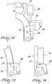
- Figures 12-14 show another embodiment of the device, in which there is a third actuator, for example a cylinder 23, which connects the support 10 to the auxiliary frame 18.
- a third actuator for example a cylinder 23, which connects the support 10 to the auxiliary frame 18.
- it is the third actuator 23 that actuates the rotation of the support 10 about the hinge with the auxiliary frame 18, until it engages the retention element 21 in the seat provided in the hook 22 that is hinged to the auxiliary frame 18.
- the bead 301 passes from below to above the edge 201 of the rim 200.
- the tool 4 arranges the bead 301 on the edge 201 of the rim 200 by means of the release of the linkage 5 on the part of the first actuator 13 and the simultaneous or non-simultaneous movement of the linkage 5 in a direction that is transverse to the axis 203 of the rim 200.
- a fourth step the procedure for the removal of the bead 301 is completed by turning the rim 200 about its own axis 203 and using the tool 4 as a guide for its complete exit.
- the invention achieves the intended aim and objects, providing a device that allows to mount and/or remove a tire on/from the rim, avoiding damage to the rim itself.
- the device according to the present invention is constituted by a pincers element 2 that is formed by a tool 4 that has an end 41, 42 that is shaped like a hook in order to grip the bead 301 of the tire.
- the tool 4 is articulated to the arm 6, which has an end that is shaped like a presser and the other end that is hinged to the articulation system.
- the two elements 4 and 6 can move with respect to each other and face each other so as to constitute the arms of a pincer.
- the two elements 4 and 6, of which one or both are fixed and/or extensible, are coupled and face each other so as to constitute pincers; the actuators, by means of the articulation system, move the two elements with respect to each other in order to grip/engage the bead of the tire, applying a clamping force thereto. Therefore, the two elements that constitute the pincers, again by means of the actuators and the articulation system, move the bead enclosed between them between two opposite positions with respect to the edge of the rim.
- the two elements that constitute the pincers of the device according to the present invention allow to move the bead in the correct manner by virtue of the locking action, following it around the rim.
- the bead of the tire is rotated in the opposite direction with respect to traditional systems, which emulate the operation of the simple lever between the rim and the tire used in the past, and strip from the rim the bead, which naturally rotates in the opposite direction with respect to the edge of the rim.
- the materials used, as well as the dimensions, may of course be any according to the requirements and the state of the art.
Landscapes
- Engineering & Computer Science (AREA)
- Mechanical Engineering (AREA)
- Tyre Moulding (AREA)
- Tires In General (AREA)
Applications Claiming Priority (1)
| Application Number | Priority Date | Filing Date | Title |
|---|---|---|---|
| IT201900022317 | 2019-11-27 |
Publications (2)
| Publication Number | Publication Date |
|---|---|
| EP3828014A1 true EP3828014A1 (de) | 2021-06-02 |
| EP3828014B1 EP3828014B1 (de) | 2023-06-28 |
Family
ID=69904074
Family Applications (1)
| Application Number | Title | Priority Date | Filing Date |
|---|---|---|---|
| EP20209684.8A Active EP3828014B1 (de) | 2019-11-27 | 2020-11-25 | Vorrichtung zur montage und demontage eines reifens auf und von einer felge |
Country Status (5)
| Country | Link |
|---|---|
| US (1) | US20210155061A1 (de) |
| EP (1) | EP3828014B1 (de) |
| JP (1) | JP2021091395A (de) |
| CN (1) | CN112848819B (de) |
| ES (1) | ES2955697T3 (de) |
Families Citing this family (1)
| Publication number | Priority date | Publication date | Assignee | Title |
|---|---|---|---|---|
| KR102656892B1 (ko) * | 2023-08-22 | 2024-04-11 | 정해도 | 타이어 재활용을 위한 휠 절단 분리장치 |
Citations (12)
| Publication number | Priority date | Publication date | Assignee | Title |
|---|---|---|---|---|
| US1439381A (en) | 1920-04-19 | 1922-12-19 | Gustaf A Safstrom | Tire tool |
| US2009338A (en) | 1934-07-24 | 1935-07-23 | Orville C Brown | Tire tool |
| US7497761B2 (en) | 2005-03-23 | 2009-03-03 | Butler Engineering & Marketing Spa | Tool for automatically assembling-disassembling a tire to/from a wheel rim |
| US20090266494A1 (en) | 2008-04-17 | 2009-10-29 | Snap-On Equipment Srl A Unico Socio | Method of and apparatus for fitting or removing a motor vehicle tyre |
| ITMI20102172A1 (it) * | 2010-11-23 | 2012-05-24 | Pogliani & Rivolta S P A | Apparato per il montaggio e lo smontaggio di uno pneumatico dal/sul relativo cerchio |
| US20120291959A1 (en) | 2011-05-20 | 2012-11-22 | Tullio Gonzaga | Device for the automatic demounting of a tire from a rim and machine equipped with such device |
| US20140223741A1 (en) | 2009-11-05 | 2014-08-14 | Corghi S.P.A. | Apparatus and method for mounting and removing tyres on and from respective wheel rims |
| US20150144273A1 (en) | 2013-11-22 | 2015-05-28 | Butler Engineering & Marketing S.P.A. | Device for demounting a tired wheel as well as a machine including such device |
| US20160001618A1 (en) | 2014-07-03 | 2016-01-07 | Corghi S.P.A. | Machine and method for fitting and removing a tyre |
| US20160023524A1 (en) | 2014-07-28 | 2016-01-28 | Butler Engineering & Marketing S.P.A. | Device for assembling-disassembling a tyred wheel, as well as machine comprising such a device |
| US20160129739A1 (en) | 2014-11-11 | 2016-05-12 | Snap-On Equipment Srl A Unico Socio | Tyre mounting/demounting tool |
| US20180104997A1 (en) | 2016-10-18 | 2018-04-19 | Corghi S.P.A. | Tyre changing machine |
Family Cites Families (13)
| Publication number | Priority date | Publication date | Assignee | Title |
|---|---|---|---|---|
| DE1605708B2 (de) * | 1966-07-06 | 1977-02-17 | Gebr. Hofmann Kg Maschinenfabrik, 6100 Darmstadt | Reifenmontier- und demontiermaschine |
| IT1063154B (it) * | 1979-05-08 | 1985-02-11 | Mondolfe Femme S P A | Dispositivo per la rimozione dei pneumatici dai cerchioni in ruote per automobile,motocicli e simili |
| IT1319475B1 (it) * | 2000-08-03 | 2003-10-10 | Corghi Spa | Dispositivo automatico per lo smontaggio ed il montaggio deipneumatici, e macchine smontagomme cosi' attrezzate |
| ITVR20020013A1 (it) * | 2002-02-12 | 2003-08-12 | Butler Eng & Marketing | Gruppo di stallonamento e smontaggio di pneumatici da cerchioni particolarmente per macchine smontagomme. |
| ITMO20060273A1 (it) * | 2006-09-08 | 2008-03-09 | Giuliano Spa | Macchina per il montaggio e lo smontaggio di pneumatici e cerchi di ruote per veicoli |
| ITMI20062076A1 (it) * | 2006-10-27 | 2008-04-28 | C M L S N C Di Marco Galbiati & C | Testata di lavoro per macchina smontagonmme e relativa macchina smontagomme |
| IT1403494B1 (it) * | 2010-12-23 | 2013-10-17 | Butler Eng & Marketing | Dispositivo di smontaggio del secondo tallone di un pneumatico da un cerchione e relativo metodo di smontaggio |
| US8973639B2 (en) * | 2011-12-29 | 2015-03-10 | Android Industries Llc | System and method for processing a tire-wheel assembly |
| ITBO20120189A1 (it) * | 2012-04-11 | 2013-10-12 | Corghi Spa | Utensile di smontaggio per una macchina smontagomme e macchina smontagomme |
| ITMO20130274A1 (it) * | 2013-09-30 | 2015-03-31 | Sicam Srl | Macchina smontagomme |
| JP6430862B2 (ja) * | 2015-03-12 | 2018-11-28 | 安全自動車株式会社 | タイヤ脱着用クリップ、タイヤ離脱方法及びタイヤ装着方法 |
| IT201600071778A1 (it) * | 2016-07-08 | 2018-01-08 | Butler Eng And Marketing S P A | Gruppo di stallonamento di una ruota gommata e/o di spinta di una porzione di un pneumatico di una ruota gommata |
| IT202100012638A1 (it) * | 2021-05-17 | 2022-11-17 | M & B Eng S R L | Dispositivo per il montaggio e lo smontaggio di un pneumatico su un cerchione |
-
2020
- 2020-11-25 US US17/104,356 patent/US20210155061A1/en not_active Abandoned
- 2020-11-25 ES ES20209684T patent/ES2955697T3/es active Active
- 2020-11-25 EP EP20209684.8A patent/EP3828014B1/de active Active
- 2020-11-26 JP JP2020195976A patent/JP2021091395A/ja active Pending
- 2020-11-27 CN CN202011358919.XA patent/CN112848819B/zh not_active Expired - Fee Related
Patent Citations (12)
| Publication number | Priority date | Publication date | Assignee | Title |
|---|---|---|---|---|
| US1439381A (en) | 1920-04-19 | 1922-12-19 | Gustaf A Safstrom | Tire tool |
| US2009338A (en) | 1934-07-24 | 1935-07-23 | Orville C Brown | Tire tool |
| US7497761B2 (en) | 2005-03-23 | 2009-03-03 | Butler Engineering & Marketing Spa | Tool for automatically assembling-disassembling a tire to/from a wheel rim |
| US20090266494A1 (en) | 2008-04-17 | 2009-10-29 | Snap-On Equipment Srl A Unico Socio | Method of and apparatus for fitting or removing a motor vehicle tyre |
| US20140223741A1 (en) | 2009-11-05 | 2014-08-14 | Corghi S.P.A. | Apparatus and method for mounting and removing tyres on and from respective wheel rims |
| ITMI20102172A1 (it) * | 2010-11-23 | 2012-05-24 | Pogliani & Rivolta S P A | Apparato per il montaggio e lo smontaggio di uno pneumatico dal/sul relativo cerchio |
| US20120291959A1 (en) | 2011-05-20 | 2012-11-22 | Tullio Gonzaga | Device for the automatic demounting of a tire from a rim and machine equipped with such device |
| US20150144273A1 (en) | 2013-11-22 | 2015-05-28 | Butler Engineering & Marketing S.P.A. | Device for demounting a tired wheel as well as a machine including such device |
| US20160001618A1 (en) | 2014-07-03 | 2016-01-07 | Corghi S.P.A. | Machine and method for fitting and removing a tyre |
| US20160023524A1 (en) | 2014-07-28 | 2016-01-28 | Butler Engineering & Marketing S.P.A. | Device for assembling-disassembling a tyred wheel, as well as machine comprising such a device |
| US20160129739A1 (en) | 2014-11-11 | 2016-05-12 | Snap-On Equipment Srl A Unico Socio | Tyre mounting/demounting tool |
| US20180104997A1 (en) | 2016-10-18 | 2018-04-19 | Corghi S.P.A. | Tyre changing machine |
Also Published As
| Publication number | Publication date |
|---|---|
| CN112848819A (zh) | 2021-05-28 |
| US20210155061A1 (en) | 2021-05-27 |
| CN112848819B (zh) | 2024-05-14 |
| JP2021091395A (ja) | 2021-06-17 |
| EP3828014B1 (de) | 2023-06-28 |
| ES2955697T3 (es) | 2023-12-05 |
Similar Documents
| Publication | Publication Date | Title |
|---|---|---|
| EP2650147B1 (de) | Reifenabziehwerkzeug für eine Reifenabziehmaschine und eine Reifenabziehmaschine | |
| EP1714807B1 (de) | Werkzeug für die automatische Montage oder Demontage eines Reifens auf/ von die/der Felge | |
| US6823922B2 (en) | Bead releasing and removing head for a tire-fitting machine, for assembling/disassembling a tire | |
| EP2468541B1 (de) | Vorrichtung zur Demontage des zweiten Wulstes eines Reifens von einer Felge und die entsprechende Methode dazu | |
| JP5935160B2 (ja) | タイヤ交換機械のためのビード破壊ユニット | |
| EP3828014B1 (de) | Vorrichtung zur montage und demontage eines reifens auf und von einer felge | |
| US20040055712A1 (en) | Simplified automatic tyre demounting device, and tyre removal machines equipped therewith | |
| JP6632241B2 (ja) | タイヤ付ホイールを取り付けおよび/または取り外しするための装置、タイヤ取り付け・取り外しマシン、およびタイヤ付ホイールのリムからタイヤを取り外しするための方法 | |
| EP2995478B1 (de) | Maschine zum abnehmen und anbringen von radreifen für fahrzeuge | |
| US9114675B2 (en) | Bead breaking unit for tyre changing machines | |
| EP3319820B1 (de) | Reifendemontiereinheit | |
| HUE030522T2 (en) | Equipment for bending metal bars such as circular cross-sections or workpieces for similar purposes | |
| EP2527166A1 (de) | Reifenwulstabdrückvorrichtung für Reifenwechselmaschinen | |
| JP2004284580A (ja) | ホイールにタイヤを着脱する装置 | |
| EP1714876A2 (de) | Wickelmaschine | |
| US20110100559A1 (en) | Device for lifting a bottom side wall of a tyre in a tyre removing machine | |
| ITMI20102172A1 (it) | Apparato per il montaggio e lo smontaggio di uno pneumatico dal/sul relativo cerchio | |
| US11142356B2 (en) | Device and method for assisting in the filling and closing operation of a package and station for filling and closing a package in a packaging machine which comprises said device | |
| US20240246376A1 (en) | Device for fitting/removing tires | |
| US20110030904A1 (en) | Unit for beading tires in tire changing machines or the like | |
| WO2022243813A1 (en) | Device for fitting and removing a tire on a rim | |
| JPH0318563B2 (de) | ||
| ITVR20070073A1 (it) | Macchina monta/smontagomme per il montaggio/smontaggio automatico di un pneumatico da un cerchione e relativo procedimento di montaggio/smontaggio |
Legal Events
| Date | Code | Title | Description |
|---|---|---|---|
| PUAI | Public reference made under article 153(3) epc to a published international application that has entered the european phase |
Free format text: ORIGINAL CODE: 0009012 |
|
| STAA | Information on the status of an ep patent application or granted ep patent |
Free format text: STATUS: THE APPLICATION HAS BEEN PUBLISHED |
|
| AK | Designated contracting states |
Kind code of ref document: A1 Designated state(s): AL AT BE BG CH CY CZ DE DK EE ES FI FR GB GR HR HU IE IS IT LI LT LU LV MC MK MT NL NO PL PT RO RS SE SI SK SM TR |
|
| STAA | Information on the status of an ep patent application or granted ep patent |
Free format text: STATUS: REQUEST FOR EXAMINATION WAS MADE |
|
| 17P | Request for examination filed |
Effective date: 20211109 |
|
| RBV | Designated contracting states (corrected) |
Designated state(s): AL AT BE BG CH CY CZ DE DK EE ES FI FR GB GR HR HU IE IS IT LI LT LU LV MC MK MT NL NO PL PT RO RS SE SI SK SM TR |
|
| STAA | Information on the status of an ep patent application or granted ep patent |
Free format text: STATUS: EXAMINATION IS IN PROGRESS |
|
| 17Q | First examination report despatched |
Effective date: 20220414 |
|
| GRAP | Despatch of communication of intention to grant a patent |
Free format text: ORIGINAL CODE: EPIDOSNIGR1 |
|
| STAA | Information on the status of an ep patent application or granted ep patent |
Free format text: STATUS: GRANT OF PATENT IS INTENDED |
|
| INTG | Intention to grant announced |
Effective date: 20230124 |
|
| GRAS | Grant fee paid |
Free format text: ORIGINAL CODE: EPIDOSNIGR3 |
|
| GRAA | (expected) grant |
Free format text: ORIGINAL CODE: 0009210 |
|
| STAA | Information on the status of an ep patent application or granted ep patent |
Free format text: STATUS: THE PATENT HAS BEEN GRANTED |
|
| P01 | Opt-out of the competence of the unified patent court (upc) registered |
Effective date: 20230515 |
|
| AK | Designated contracting states |
Kind code of ref document: B1 Designated state(s): AL AT BE BG CH CY CZ DE DK EE ES FI FR GB GR HR HU IE IS IT LI LT LU LV MC MK MT NL NO PL PT RO RS SE SI SK SM TR |
|
| REG | Reference to a national code |
Ref country code: CH Ref legal event code: EP |
|
| REG | Reference to a national code |
Ref country code: AT Ref legal event code: REF Ref document number: 1582405 Country of ref document: AT Kind code of ref document: T Effective date: 20230715 |
|
| REG | Reference to a national code |
Ref country code: IE Ref legal event code: FG4D |
|
| REG | Reference to a national code |
Ref country code: DE Ref legal event code: R096 Ref document number: 602020012977 Country of ref document: DE |
|
| REG | Reference to a national code |
Ref country code: LT Ref legal event code: MG9D |
|
| PG25 | Lapsed in a contracting state [announced via postgrant information from national office to epo] |
Ref country code: SE Free format text: LAPSE BECAUSE OF FAILURE TO SUBMIT A TRANSLATION OF THE DESCRIPTION OR TO PAY THE FEE WITHIN THE PRESCRIBED TIME-LIMIT Effective date: 20230628 Ref country code: NO Free format text: LAPSE BECAUSE OF FAILURE TO SUBMIT A TRANSLATION OF THE DESCRIPTION OR TO PAY THE FEE WITHIN THE PRESCRIBED TIME-LIMIT Effective date: 20230928 |
|
| REG | Reference to a national code |
Ref country code: NL Ref legal event code: MP Effective date: 20230628 |
|
| REG | Reference to a national code |
Ref country code: AT Ref legal event code: MK05 Ref document number: 1582405 Country of ref document: AT Kind code of ref document: T Effective date: 20230628 |
|
| PG25 | Lapsed in a contracting state [announced via postgrant information from national office to epo] |
Ref country code: RS Free format text: LAPSE BECAUSE OF FAILURE TO SUBMIT A TRANSLATION OF THE DESCRIPTION OR TO PAY THE FEE WITHIN THE PRESCRIBED TIME-LIMIT Effective date: 20230628 Ref country code: NL Free format text: LAPSE BECAUSE OF FAILURE TO SUBMIT A TRANSLATION OF THE DESCRIPTION OR TO PAY THE FEE WITHIN THE PRESCRIBED TIME-LIMIT Effective date: 20230628 Ref country code: LV Free format text: LAPSE BECAUSE OF FAILURE TO SUBMIT A TRANSLATION OF THE DESCRIPTION OR TO PAY THE FEE WITHIN THE PRESCRIBED TIME-LIMIT Effective date: 20230628 Ref country code: LT Free format text: LAPSE BECAUSE OF FAILURE TO SUBMIT A TRANSLATION OF THE DESCRIPTION OR TO PAY THE FEE WITHIN THE PRESCRIBED TIME-LIMIT Effective date: 20230628 Ref country code: HR Free format text: LAPSE BECAUSE OF FAILURE TO SUBMIT A TRANSLATION OF THE DESCRIPTION OR TO PAY THE FEE WITHIN THE PRESCRIBED TIME-LIMIT Effective date: 20230628 Ref country code: GR Free format text: LAPSE BECAUSE OF FAILURE TO SUBMIT A TRANSLATION OF THE DESCRIPTION OR TO PAY THE FEE WITHIN THE PRESCRIBED TIME-LIMIT Effective date: 20230929 |
|
| REG | Reference to a national code |
Ref country code: ES Ref legal event code: FG2A Ref document number: 2955697 Country of ref document: ES Kind code of ref document: T3 Effective date: 20231205 |
|
| PG25 | Lapsed in a contracting state [announced via postgrant information from national office to epo] |
Ref country code: FI Free format text: LAPSE BECAUSE OF FAILURE TO SUBMIT A TRANSLATION OF THE DESCRIPTION OR TO PAY THE FEE WITHIN THE PRESCRIBED TIME-LIMIT Effective date: 20230628 |
|
| PG25 | Lapsed in a contracting state [announced via postgrant information from national office to epo] |
Ref country code: SK Free format text: LAPSE BECAUSE OF FAILURE TO SUBMIT A TRANSLATION OF THE DESCRIPTION OR TO PAY THE FEE WITHIN THE PRESCRIBED TIME-LIMIT Effective date: 20230628 |
|
| PGFP | Annual fee paid to national office [announced via postgrant information from national office to epo] |
Ref country code: ES Payment date: 20231201 Year of fee payment: 4 |
|
| PG25 | Lapsed in a contracting state [announced via postgrant information from national office to epo] |
Ref country code: IS Free format text: LAPSE BECAUSE OF FAILURE TO SUBMIT A TRANSLATION OF THE DESCRIPTION OR TO PAY THE FEE WITHIN THE PRESCRIBED TIME-LIMIT Effective date: 20231028 |
|
| PG25 | Lapsed in a contracting state [announced via postgrant information from national office to epo] |
Ref country code: SM Free format text: LAPSE BECAUSE OF FAILURE TO SUBMIT A TRANSLATION OF THE DESCRIPTION OR TO PAY THE FEE WITHIN THE PRESCRIBED TIME-LIMIT Effective date: 20230628 Ref country code: SK Free format text: LAPSE BECAUSE OF FAILURE TO SUBMIT A TRANSLATION OF THE DESCRIPTION OR TO PAY THE FEE WITHIN THE PRESCRIBED TIME-LIMIT Effective date: 20230628 Ref country code: RO Free format text: LAPSE BECAUSE OF FAILURE TO SUBMIT A TRANSLATION OF THE DESCRIPTION OR TO PAY THE FEE WITHIN THE PRESCRIBED TIME-LIMIT Effective date: 20230628 Ref country code: PT Free format text: LAPSE BECAUSE OF FAILURE TO SUBMIT A TRANSLATION OF THE DESCRIPTION OR TO PAY THE FEE WITHIN THE PRESCRIBED TIME-LIMIT Effective date: 20231030 Ref country code: IS Free format text: LAPSE BECAUSE OF FAILURE TO SUBMIT A TRANSLATION OF THE DESCRIPTION OR TO PAY THE FEE WITHIN THE PRESCRIBED TIME-LIMIT Effective date: 20231028 Ref country code: EE Free format text: LAPSE BECAUSE OF FAILURE TO SUBMIT A TRANSLATION OF THE DESCRIPTION OR TO PAY THE FEE WITHIN THE PRESCRIBED TIME-LIMIT Effective date: 20230628 Ref country code: CZ Free format text: LAPSE BECAUSE OF FAILURE TO SUBMIT A TRANSLATION OF THE DESCRIPTION OR TO PAY THE FEE WITHIN THE PRESCRIBED TIME-LIMIT Effective date: 20230628 Ref country code: AT Free format text: LAPSE BECAUSE OF FAILURE TO SUBMIT A TRANSLATION OF THE DESCRIPTION OR TO PAY THE FEE WITHIN THE PRESCRIBED TIME-LIMIT Effective date: 20230628 |
|
| PGFP | Annual fee paid to national office [announced via postgrant information from national office to epo] |
Ref country code: FR Payment date: 20231127 Year of fee payment: 4 Ref country code: DE Payment date: 20231129 Year of fee payment: 4 |
|
| PG25 | Lapsed in a contracting state [announced via postgrant information from national office to epo] |
Ref country code: PL Free format text: LAPSE BECAUSE OF FAILURE TO SUBMIT A TRANSLATION OF THE DESCRIPTION OR TO PAY THE FEE WITHIN THE PRESCRIBED TIME-LIMIT Effective date: 20230628 |
|
| REG | Reference to a national code |
Ref country code: DE Ref legal event code: R097 Ref document number: 602020012977 Country of ref document: DE |
|
| PG25 | Lapsed in a contracting state [announced via postgrant information from national office to epo] |
Ref country code: DK Free format text: LAPSE BECAUSE OF FAILURE TO SUBMIT A TRANSLATION OF THE DESCRIPTION OR TO PAY THE FEE WITHIN THE PRESCRIBED TIME-LIMIT Effective date: 20230628 |
|
| PLBE | No opposition filed within time limit |
Free format text: ORIGINAL CODE: 0009261 |
|
| STAA | Information on the status of an ep patent application or granted ep patent |
Free format text: STATUS: NO OPPOSITION FILED WITHIN TIME LIMIT |
|
| 26N | No opposition filed |
Effective date: 20240402 |
|
| REG | Reference to a national code |
Ref country code: CH Ref legal event code: PL |
|
| PG25 | Lapsed in a contracting state [announced via postgrant information from national office to epo] |
Ref country code: MC Free format text: LAPSE BECAUSE OF FAILURE TO SUBMIT A TRANSLATION OF THE DESCRIPTION OR TO PAY THE FEE WITHIN THE PRESCRIBED TIME-LIMIT Effective date: 20230628 |
|
| PG25 | Lapsed in a contracting state [announced via postgrant information from national office to epo] |
Ref country code: LU Free format text: LAPSE BECAUSE OF NON-PAYMENT OF DUE FEES Effective date: 20231125 |
|
| PG25 | Lapsed in a contracting state [announced via postgrant information from national office to epo] |
Ref country code: CH Free format text: LAPSE BECAUSE OF NON-PAYMENT OF DUE FEES Effective date: 20231130 |
|
| PG25 | Lapsed in a contracting state [announced via postgrant information from national office to epo] |
Ref country code: MC Free format text: LAPSE BECAUSE OF FAILURE TO SUBMIT A TRANSLATION OF THE DESCRIPTION OR TO PAY THE FEE WITHIN THE PRESCRIBED TIME-LIMIT Effective date: 20230628 Ref country code: LU Free format text: LAPSE BECAUSE OF NON-PAYMENT OF DUE FEES Effective date: 20231125 Ref country code: CH Free format text: LAPSE BECAUSE OF NON-PAYMENT OF DUE FEES Effective date: 20231130 Ref country code: SI Free format text: LAPSE BECAUSE OF FAILURE TO SUBMIT A TRANSLATION OF THE DESCRIPTION OR TO PAY THE FEE WITHIN THE PRESCRIBED TIME-LIMIT Effective date: 20230628 |
|
| REG | Reference to a national code |
Ref country code: BE Ref legal event code: MM Effective date: 20231130 |
|
| REG | Reference to a national code |
Ref country code: IE Ref legal event code: MM4A |
|
| PG25 | Lapsed in a contracting state [announced via postgrant information from national office to epo] |
Ref country code: IE Free format text: LAPSE BECAUSE OF NON-PAYMENT OF DUE FEES Effective date: 20231125 |
|
| PG25 | Lapsed in a contracting state [announced via postgrant information from national office to epo] |
Ref country code: BE Free format text: LAPSE BECAUSE OF NON-PAYMENT OF DUE FEES Effective date: 20231130 |
|
| PG25 | Lapsed in a contracting state [announced via postgrant information from national office to epo] |
Ref country code: IE Free format text: LAPSE BECAUSE OF NON-PAYMENT OF DUE FEES Effective date: 20231125 Ref country code: BE Free format text: LAPSE BECAUSE OF NON-PAYMENT OF DUE FEES Effective date: 20231130 |
|
| PG25 | Lapsed in a contracting state [announced via postgrant information from national office to epo] |
Ref country code: BG Free format text: LAPSE BECAUSE OF FAILURE TO SUBMIT A TRANSLATION OF THE DESCRIPTION OR TO PAY THE FEE WITHIN THE PRESCRIBED TIME-LIMIT Effective date: 20230628 |
|
| PG25 | Lapsed in a contracting state [announced via postgrant information from national office to epo] |
Ref country code: BG Free format text: LAPSE BECAUSE OF FAILURE TO SUBMIT A TRANSLATION OF THE DESCRIPTION OR TO PAY THE FEE WITHIN THE PRESCRIBED TIME-LIMIT Effective date: 20230628 |
|
| PGFP | Annual fee paid to national office [announced via postgrant information from national office to epo] |
Ref country code: IT Payment date: 20241119 Year of fee payment: 5 |
|
| REG | Reference to a national code |
Ref country code: DE Ref legal event code: R119 Ref document number: 602020012977 Country of ref document: DE |
|
| GBPC | Gb: european patent ceased through non-payment of renewal fee |
Effective date: 20241125 |
|
| PG25 | Lapsed in a contracting state [announced via postgrant information from national office to epo] |
Ref country code: CY Free format text: LAPSE BECAUSE OF FAILURE TO SUBMIT A TRANSLATION OF THE DESCRIPTION OR TO PAY THE FEE WITHIN THE PRESCRIBED TIME-LIMIT; INVALID AB INITIO Effective date: 20201125 |
|
| PG25 | Lapsed in a contracting state [announced via postgrant information from national office to epo] |
Ref country code: HU Free format text: LAPSE BECAUSE OF FAILURE TO SUBMIT A TRANSLATION OF THE DESCRIPTION OR TO PAY THE FEE WITHIN THE PRESCRIBED TIME-LIMIT; INVALID AB INITIO Effective date: 20201125 |
|
| PG25 | Lapsed in a contracting state [announced via postgrant information from national office to epo] |
Ref country code: DE Free format text: LAPSE BECAUSE OF NON-PAYMENT OF DUE FEES Effective date: 20250603 |
|
| PG25 | Lapsed in a contracting state [announced via postgrant information from national office to epo] |
Ref country code: GB Free format text: LAPSE BECAUSE OF NON-PAYMENT OF DUE FEES Effective date: 20241125 |
|
| PG25 | Lapsed in a contracting state [announced via postgrant information from national office to epo] |
Ref country code: FR Free format text: LAPSE BECAUSE OF NON-PAYMENT OF DUE FEES Effective date: 20241130 |
|
| PG25 | Lapsed in a contracting state [announced via postgrant information from national office to epo] |
Ref country code: TR Free format text: LAPSE BECAUSE OF FAILURE TO SUBMIT A TRANSLATION OF THE DESCRIPTION OR TO PAY THE FEE WITHIN THE PRESCRIBED TIME-LIMIT Effective date: 20230628 |
|
| REG | Reference to a national code |
Ref country code: ES Ref legal event code: FD2A Effective date: 20251230 |
|
| PG25 | Lapsed in a contracting state [announced via postgrant information from national office to epo] |
Ref country code: ES Free format text: LAPSE BECAUSE OF NON-PAYMENT OF DUE FEES Effective date: 20241126 |