EP3827936B1 - Control method for robot system - Google Patents
Control method for robot system Download PDFInfo
- Publication number
- EP3827936B1 EP3827936B1 EP20208180.8A EP20208180A EP3827936B1 EP 3827936 B1 EP3827936 B1 EP 3827936B1 EP 20208180 A EP20208180 A EP 20208180A EP 3827936 B1 EP3827936 B1 EP 3827936B1
- Authority
- EP
- European Patent Office
- Prior art keywords
- vehicle
- robot arm
- work station
- electric power
- robot
- Prior art date
- Legal status (The legal status is an assumption and is not a legal conclusion. Google has not performed a legal analysis and makes no representation as to the accuracy of the status listed.)
- Active
Links
Images


Classifications
-
- B—PERFORMING OPERATIONS; TRANSPORTING
- B25—HAND TOOLS; PORTABLE POWER-DRIVEN TOOLS; MANIPULATORS
- B25J—MANIPULATORS; CHAMBERS PROVIDED WITH MANIPULATION DEVICES
- B25J9/00—Program-controlled manipulators
- B25J9/16—Program controls
- B25J9/1602—Program controls characterised by the control system, structure, architecture
-
- B—PERFORMING OPERATIONS; TRANSPORTING
- B25—HAND TOOLS; PORTABLE POWER-DRIVEN TOOLS; MANIPULATORS
- B25J—MANIPULATORS; CHAMBERS PROVIDED WITH MANIPULATION DEVICES
- B25J9/00—Program-controlled manipulators
- B25J9/16—Program controls
- B25J9/1615—Program controls characterised by special kind of manipulator, e.g. planar, scara, gantry, cantilever, space, closed chain, passive/active joints and tendon driven manipulators
- B25J9/162—Mobile manipulator, movable base with manipulator arm mounted on it
-
- B—PERFORMING OPERATIONS; TRANSPORTING
- B25—HAND TOOLS; PORTABLE POWER-DRIVEN TOOLS; MANIPULATORS
- B25J—MANIPULATORS; CHAMBERS PROVIDED WITH MANIPULATION DEVICES
- B25J13/00—Controls for manipulators
-
- B—PERFORMING OPERATIONS; TRANSPORTING
- B25—HAND TOOLS; PORTABLE POWER-DRIVEN TOOLS; MANIPULATORS
- B25J—MANIPULATORS; CHAMBERS PROVIDED WITH MANIPULATION DEVICES
- B25J13/00—Controls for manipulators
- B25J13/08—Controls for manipulators by means of sensing devices, e.g. viewing or touching devices
- B25J13/088—Controls for manipulators by means of sensing devices, e.g. viewing or touching devices with position, velocity or acceleration sensors
- B25J13/089—Determining the position of the robot with reference to its environment
-
- B—PERFORMING OPERATIONS; TRANSPORTING
- B25—HAND TOOLS; PORTABLE POWER-DRIVEN TOOLS; MANIPULATORS
- B25J—MANIPULATORS; CHAMBERS PROVIDED WITH MANIPULATION DEVICES
- B25J19/00—Accessories fitted to manipulators, e.g. for monitoring, for viewing; Safety devices combined with or specially adapted for use in connection with manipulators
- B25J19/0025—Means for supplying energy to the end effector
-
- G—PHYSICS
- G05—CONTROLLING; REGULATING
- G05B—CONTROL OR REGULATING SYSTEMS IN GENERAL; FUNCTIONAL ELEMENTS OF SUCH SYSTEMS; MONITORING OR TESTING ARRANGEMENTS FOR SUCH SYSTEMS OR ELEMENTS
- G05B19/00—Program-control systems
- G05B19/02—Program-control systems electric
- G05B19/418—Total factory control, i.e. centrally controlling a plurality of machines, e.g. direct or distributed numerical control [DNC], flexible manufacturing systems [FMS], integrated manufacturing systems [IMS] or computer integrated manufacturing [CIM]
- G05B19/4189—Total factory control, i.e. centrally controlling a plurality of machines, e.g. direct or distributed numerical control [DNC], flexible manufacturing systems [FMS], integrated manufacturing systems [IMS] or computer integrated manufacturing [CIM] characterised by the transport system
- G05B19/41895—Total factory control, i.e. centrally controlling a plurality of machines, e.g. direct or distributed numerical control [DNC], flexible manufacturing systems [FMS], integrated manufacturing systems [IMS] or computer integrated manufacturing [CIM] characterised by the transport system using automatic guided vehicles [AGV]
-
- G—PHYSICS
- G05—CONTROLLING; REGULATING
- G05B—CONTROL OR REGULATING SYSTEMS IN GENERAL; FUNCTIONAL ELEMENTS OF SUCH SYSTEMS; MONITORING OR TESTING ARRANGEMENTS FOR SUCH SYSTEMS OR ELEMENTS
- G05B2219/00—Program-control systems
- G05B2219/30—Nc systems
- G05B2219/31—From computer integrated manufacturing till monitoring
- G05B2219/31004—Move vehicle to battery charge or maintenance area
-
- G—PHYSICS
- G05—CONTROLLING; REGULATING
- G05B—CONTROL OR REGULATING SYSTEMS IN GENERAL; FUNCTIONAL ELEMENTS OF SUCH SYSTEMS; MONITORING OR TESTING ARRANGEMENTS FOR SUCH SYSTEMS OR ELEMENTS
- G05B2219/00—Program-control systems
- G05B2219/30—Nc systems
- G05B2219/34—Director, elements to supervisory
- G05B2219/34306—Power down, energy saving
-
- G—PHYSICS
- G05—CONTROLLING; REGULATING
- G05B—CONTROL OR REGULATING SYSTEMS IN GENERAL; FUNCTIONAL ELEMENTS OF SUCH SYSTEMS; MONITORING OR TESTING ARRANGEMENTS FOR SUCH SYSTEMS OR ELEMENTS
- G05B2219/00—Program-control systems
- G05B2219/30—Nc systems
- G05B2219/34—Director, elements to supervisory
- G05B2219/34315—Power supply turning on or shutting off
-
- G—PHYSICS
- G05—CONTROLLING; REGULATING
- G05B—CONTROL OR REGULATING SYSTEMS IN GENERAL; FUNCTIONAL ELEMENTS OF SUCH SYSTEMS; MONITORING OR TESTING ARRANGEMENTS FOR SUCH SYSTEMS OR ELEMENTS
- G05B2219/00—Program-control systems
- G05B2219/30—Nc systems
- G05B2219/40—Robotics, robotics mapping to robotics vision
- G05B2219/40298—Manipulator on vehicle, wheels, mobile
-
- Y—GENERAL TAGGING OF NEW TECHNOLOGICAL DEVELOPMENTS; GENERAL TAGGING OF CROSS-SECTIONAL TECHNOLOGIES SPANNING OVER SEVERAL SECTIONS OF THE IPC; TECHNICAL SUBJECTS COVERED BY FORMER USPC CROSS-REFERENCE ART COLLECTIONS [XRACs] AND DIGESTS
- Y02—TECHNOLOGIES OR APPLICATIONS FOR MITIGATION OR ADAPTATION AGAINST CLIMATE CHANGE
- Y02P—CLIMATE CHANGE MITIGATION TECHNOLOGIES IN THE PRODUCTION OR PROCESSING OF GOODS
- Y02P70/00—Climate change mitigation technologies in the production process for final industrial or consumer products
- Y02P70/10—Greenhouse gas [GHG] capture, material saving, heat recovery or other energy efficient measures, e.g. motor control, characterised by manufacturing processes, e.g. for rolling metal or metal working
-
- Y—GENERAL TAGGING OF NEW TECHNOLOGICAL DEVELOPMENTS; GENERAL TAGGING OF CROSS-SECTIONAL TECHNOLOGIES SPANNING OVER SEVERAL SECTIONS OF THE IPC; TECHNICAL SUBJECTS COVERED BY FORMER USPC CROSS-REFERENCE ART COLLECTIONS [XRACs] AND DIGESTS
- Y02—TECHNOLOGIES OR APPLICATIONS FOR MITIGATION OR ADAPTATION AGAINST CLIMATE CHANGE
- Y02P—CLIMATE CHANGE MITIGATION TECHNOLOGIES IN THE PRODUCTION OR PROCESSING OF GOODS
- Y02P90/00—Enabling technologies with a potential contribution to greenhouse gas [GHG] emissions mitigation
- Y02P90/02—Total factory control, e.g. smart factories, flexible manufacturing systems [FMS] or integrated manufacturing systems [IMS]
-
- Y—GENERAL TAGGING OF NEW TECHNOLOGICAL DEVELOPMENTS; GENERAL TAGGING OF CROSS-SECTIONAL TECHNOLOGIES SPANNING OVER SEVERAL SECTIONS OF THE IPC; TECHNICAL SUBJECTS COVERED BY FORMER USPC CROSS-REFERENCE ART COLLECTIONS [XRACs] AND DIGESTS
- Y02—TECHNOLOGIES OR APPLICATIONS FOR MITIGATION OR ADAPTATION AGAINST CLIMATE CHANGE
- Y02P—CLIMATE CHANGE MITIGATION TECHNOLOGIES IN THE PRODUCTION OR PROCESSING OF GOODS
- Y02P90/00—Enabling technologies with a potential contribution to greenhouse gas [GHG] emissions mitigation
- Y02P90/60—Electric or hybrid propulsion means for production processes
Definitions
- the present disclosure relates to a control method for a robot system.
- Patent Literature 1 the stop of the supply of the electric power to the joint motors of the leg sections used for movement of the robot is described.
- electric power consumed by a robot arm, which executes work after completion of the movement of the robot is not considered.
- the inventors of this application examined a technique for, in a robot including a robot arm and a moving mechanism, stopping supply of electric power to an electric motor for driving joints of the robot arm during movement of the robot.
- Patent Literature 2 JP 2018-118341 A discloses a work robot performing work in a production line.
- the work robot comprises a moving unit that is movable between stations in the production line, a working unit in the station, and an operating power supply unit that supplies power for operation to the working unit, and a connector portion having a signal terminal portion for transmitting a work signal to the working portion and a gas conducting connection portion for supplying working gas to the working portion.
- Patent Literature 3 discloses a battery-driven legged robot and a method of controlling the robot.
- the robot can operate for a longer time, and energy, which is required for the motion for connection to a charging station or an external power supply device, can be maintained.
- a control method for a robot system according to claim 1 is provided.
- FIG. 1 is an explanatory diagram schematically showing an autonomous mobile robot 1 in a first embodiment.
- the autonomous mobile robot 1 receives an instruction of a host management device 600 and autonomously operates.
- the autonomous mobile robot 1 is a so-called AMR.
- the autonomous mobile robot 1 includes a robot 100, an end effector 200, an operation control device 300, and a vehicle 700.
- the reference coordinate system BC is a three-dimensional orthogonal coordinate system defined by an X axis and a Y axis orthogonal to each other on a plane on which the autonomous mobile robot 1 moves and a Z axis, a positive direction of which is the vertical upward direction.
- the reference coordinate system BC is decided for each of work stations WS.
- the work stations WS are places where the autonomous mobile robot 1 performs work.
- the work stations WS are explained below.
- the robot coordinate system RC is a coordinate system fixed with respect to the autonomous mobile robot 1.
- the upward direction of the autonomous mobile robot 1 is a Z-axis positive direction.
- the forward direction of the autonomous mobile robot 1 is an X-axis positive direction.
- a direction perpendicular to the Z axis and the X axis is a Y-axis positive direction.
- An origin Or of the robot coordinate system RC is a point located on a rotation axis of a joint J11 and in a base 180. The base 180 and the joint J11 are explained below.
- Both of the reference coordinate system BC and the robot coordinate system RC are right-handed systems.
- the robot 100 is a vertical articulated robot.
- the robot 100 includes a robot arm 110, a base 180, and a force detecting section 190.
- the robot arm 110 is supported by the base 180.
- the robot arm 110 can move the end effector 200 attached to the distal end portion of the robot arm 110.
- the robot arm 110 includes arm elements 110a to 110f and joints J11 to J16. That is, the robot 100 is a six-axis robot including the robot arm 110 including six joints J11 to J16.
- the joints J12, J13, and J15 are bending joints.
- the joints J11, J14, and J16 are twist joints.
- the base 180 and the arm element 110a are coupled via the joint J11.
- the arm element 110a and the arm element 110b are coupled via the joint J12.
- the arm element 110b and the arm element 110c are coupled via the joint J13.
- the arm element 110c and the arm element 110d are coupled via the joint J14.
- the arm element 110d and the arm element 110e are coupled via the joint J15.
- the arm element 110e and the arm element 110f are coupled via the joint J16.
- the end effector 200 is coupled to the arm element 110f on the opposite side of the arm element 110e.
- the joints J11 to J16 include servomotors 410, encoders 420, and speed reducers 510.
- the servomotors 410 are controlled by the operation control device 300 and rotate output shafts of the servomotors 410.
- the servomotors 410 include brakes. When electric power is not supplied to the servomotors 410, angle positions of the output shafts of the servomotors 410 are kept by the brakes. When electric power is supplied to the servomotors 410, the brakes are released.
- the speed reducers 510 decelerate the rotation of the output shafts of the servomotors 410 and transmit the rotation to the arm elements. That is, the robot arm 110 is driven by the servomotors 410.
- the encoders 420 detect rotation angles of the output shafts of the servomotors 410.
- a servomotor 410a, an encoder 420a, and a speed reducer 510a for driving the joint J11 are denoted by reference numerals and shown.
- illustration is omitted about the servomotors 410, the encoders 420, and the speed reducers 510 for driving the joints J12 to J16.
- the servomotors when the servomotors of the joints are referred to without being distinguished from one another, the servomotors are described as servomotor 410.
- the encoders of the joints are referred to without being distinguished from one another, the encoders are described as encoder 420.
- the speed reducers of the joints are referred to without being distinguished from one another, the speed reducers are described as speed reducer 510.
- the force detecting section 190 is provided in a lower part of the base 180.
- the force detecting section 190 can detect force applied to the robot arm 110. More specifically, the force detecting section 190 can detect forces in three axial directions of the X axis, the Y axis, and the Z axis and torques around a U axis, a V axis, and a W axis serving as rotation axes applied from the outside, that is, components other than the force detecting section 190.
- the force detecting section 190 can measure forces in the three axial directions of the X axis, the Y axis, and the Z axis and torques around the U axis, the V axis, and the W axis acting on the robot arm 110, which is a component other than the force detecting section 190.
- An output of the force detecting section 190 is transmitted to the operation control device 300 and used for control of the robot 100.
- the operation control device 300 can execute force control based on the output of the force detecting section 190.
- the robot 100 can arrange the end effector 200, which is attached to the distal end portion of the robot arm 110, at a target point, which is a designated position in a three-dimensional space, in a designated posture by respectively rotating the six joints J11 to J16 of the robot arm 110 with the servomotors.
- a point representing a position of the end effector 200 in the three-dimensional space is called TCP (Tool Center Point) as well.
- TCP Tool Center Point
- FIG. 1 the TCP serving as a control point is shown.
- the end effector 200 is attached to the distal end of the robot arm 110.
- the end effector 200 is controlled by the operation control device 300 to be able to grip a workpiece, which is a work target object, and release the gripped workpiece.
- the end effector 200 and the robot 100 are controlled by the operation control device 300 to be able to grip and move the workpiece.
- the operation control device 300 is a control device that controls the operations of the robot 100 and the end effector 200.
- the operation control device 300 is coupled to the robot 100.
- the operation control device 300 is fixed to the vehicle 700 together with the robot 100.
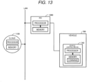
- the operation control device 300 includes a CPU (Central Processing Unit) 301, which is a processor, a RAM (Random Access Memory) 302, and a ROM (Read-Only Memory) 303.
- a control program for controlling the robot 100 is installed in the operation control device 300.
- the CPU 301, the RAM 302, and the ROM 303 functioning as hardware resources and the control program cooperate.
- the CPU 301 loads a computer program stored in the ROM 303 onto the RAM 302 and executes the computer program to thereby realize various functions.
- the vehicle 700 supports the robot arm 110 via the force detecting section 190 and the base 180.
- the vehicle 700 can move the robot 100 to any position on a floor surface.
- the vehicle 700 includes one pair of driving wheels DW, two pairs of driven wheels FW1 and FW2, servomotors 410v1 and 410v2, encoders 420v1 and 420v2, speed reducers 510v1 and 510v2, an inertial measurement unit (IMU) 710, a camera 720, a vehicle control section 740, and a storage battery 750.
- IMU inertial measurement unit
- the servomotors 410v1 and 410v2 are controlled by the operation control device 300 to rotate output shafts of the servomotors 410v1 and 410v2.
- the speed reducers 510v1 and 510v2 decelerate the rotation of the output shafts of the servomotors 410v1 and 410v2 and transmit the rotation to the two driving wheels DW.
- the rotation is transmitted to the two driving wheels DW from the speed reducers 510v1 and 510v2 to drive the two driving wheels DW.
- the encoders 420v1 and 420v2 respectively detect rotation angles of the output shafts of the servomotors 410v1 and 410v2.
- the two driving wheels DW can be respectively independently rotated by the servomotors 410v1 and 410v2. As a result, the vehicle 700 can move in any direction.
- the servomotors 410v1 and 410v2 are described as servomotor 410v.
- the encoders 420v1 and 420v2 are described as encoder 420v.
- the speed reducers 510v1 and 510v2 are described as speed reducer 510v.
- the two pairs of driven wheels FW1 and FW2 support the vehicle 700 in conjunction with the one pair of driving wheels DW.
- the driven wheels FW1 and FW2 are applied with external force to rotate.
- the driven wheels FW1 and FW2 are not driven by a motor.
- the IMU 710 can acquire information concerning accelerations in the X-axis direction, the Y-axis direction, and the Z-axis direction and angular velocities in the U-axis direction, the V-axis direction, and the W-axis direction of the vehicle 700.
- the vehicle control section 740 recognizes, based on those kinds of information, a tilt of the vehicle 700, moving speed including the speed and the direction of the vehicle 700, and a present position of the vehicle 700.
- the camera 720 can acquire an image in a predetermine angle range in the forward direction of the vehicle 700, that is, the X-axis direction of the robot coordinate system.
- the vehicle control section 740 recognizes, based on data of the image generated by the camera 720, the moving speed including the speed and the direction of the vehicle 700 and the present position of the vehicle 700. That is, the camera 720 and the vehicle control section 740 function as a position detecting section that can detect the position of the vehicle 700.
- the vehicle control section 740 is a control device that controls the operation of the vehicle 700.
- the vehicle control section 740 includes a CPU 741, which is a processor, a RAM 742, and a ROM 743.
- a control program for controlling the vehicle 700 is installed in the vehicle control section 740.
- the CPU 741, the RAM 742, and the ROM 743 functioning as hardware resources and the control program cooperate.
- the CPU 741 loads a computer program stored in the ROM 743 onto the RAM 742 and executes the computer program to thereby realize various functions.
- the storage battery 750 stores energy for driving the robot 100 and the vehicle 700.
- the servomotor 410 of the robot 100 and the servomotor 410v of the vehicle 700 are supplied with electric energy from the storage battery 750 and driven.
- the host management device 600 gives instructions to a plurality of autonomous mobile robots 1 and controls the autonomous mobile robots 1.
- the host management device 600 is coupled to the operation control device 300 of the robot 100 and the vehicle control section 740 of the vehicle 700.
- FIG. 1 to facilitate understanding of the technique, only one autonomous mobile robot 1 is shown.
- the host management device 600 includes a CPU 601, which is a processor, a RAM 602, a ROM 603, an input device 607, and an output device 608.
- a control program for controlling the plurality of autonomous mobile robots 1 is installed in the host management device 600.
- the CPU 601, the RAM 602, and the ROM 603 functioning as hardware resources and the control program cooperate.
- the CPU 601 loads a computer program stored in the ROM 603 onto the RAM 602 and executes the computer program to thereby realize various functions.
- the input device 607 receives an instruction from a user.
- the input device 607 is, for example, a mouse, a keyboard, or a touch panel.
- the output device 608 outputs various kinds of information to the user.
- the output device 608 is, for example, a display or a speaker.
- FIG. 2 is an explanatory diagram showing disposition of work stations WS1, WS2, and WS0 and a state of movement of the autonomous mobile robot 1.
- the work stations WS1, WS2, and WS0 are places where the autonomous mobile robot 1 performs work or predetermined processing is performed on the autonomous mobile robot 1.
- the work stations WS1, WS2, and WS0 are disposed in places different from one another.
- the autonomous mobile robot 1 moves among the work stations WS1, WS2, and WS0.
- the movement of the autonomous mobile robot 1 among the work stations WS1, WS2, and WS0 is indicated by arrows A12, A20, and A10.
- Information concerning a route for moving among the work stations WS1, WS2, and WS0 is stored in the RAM 742 of the vehicle control section 740 in advance prior to the movement (see the lower center of FIG. 1 ).
- the CPU 741 controls the servomotors 410v1 and 410v2 based on the information concerning the route stored in the RAM 742 and information obtained from the IMU 710 and the camera 720 to move the vehicle 700 to the work station WS in which the next work should be performed.
- the work stations WS1, WS2, and WS0 are described as work station WS.
- the work station WS1 includes trays T11 and T12. One or more workpieces WP are disposed on the tray T11.
- the autonomous mobile robot 1 performs work for moving the workpieces WP from the tray T11 to the tray T12 in the work station WS1.
- the work station WS2 has the same configuration as the configuration of the work station WS1. That is, the work station WS2 includes trays T21 and T22.
- the autonomous mobile robot 1 performs work for moving the workpieces WP from the tray T21 to the tray T22 in the work station WS2.
- the work station WS0 is a charging station. In the work station WS0, charging to the storage battery 750 of the autonomous mobile robot 1 is performed by a charging device BtC (see the lower center of FIG. 1 ). The autonomous mobile robot 1 does not drive the robot arm 110 in the work station WS0.
- FIG. 3 is a block diagram showing the configuration of an entire production system including the autonomous mobile robot 1.
- the production system includes autonomous mobile robots 1A to 1C, the host management device 600, the work stations WS1, WS2, and WS0, and a production management system PMS.
- the autonomous mobile robots 1A to 1C are the autonomous mobile robot 1 explained with reference to FIG. 1 .
- reference signs 1A, 1B, and 1C are respectively attached to the three autonomous mobile robots.
- A, B, and C are respectively attached to the ends of the vehicle control sections 740 of the vehicles 700 and the operation control devices 300 of the robots 100 included in the autonomous mobile robots 1A, 1B, and 1C to distinguish the vehicle control sections 740 and the operation control devices 300.
- the vehicle control section 740 of the vehicle 700 receives information from a vehicle allocation system 640 of the host management device 600.
- the operation control device 300 of the robot 100 receives the information via the vehicle control section 740 of the vehicle 700.
- Information Ts3 transmitted and received between the vehicle control section 740 of the vehicle 700 and the operation control device 300 of the robot 100 includes information concerning work content in the work station WS, information concerning a state of the vehicle 700, and information concerning a state of the robot 100.
- the host management device 600 realizes functions of an AMR control system 620 and the vehicle allocation system 640.
- the vehicle allocation system 640 monitors states of the autonomous mobile robots 1A to 1C.
- the vehicle allocation system 640 instructs, based on an instruction from the AMR control system 620, the autonomous mobile robots 1A to 1C about the work station WS in which work should be performed next.
- Information TS2 transmitted and received between the vehicle allocation system 640 and the vehicle control section 740 of the vehicle 700 includes information concerning the work station WS to which the vehicle 700 should move, work content in the work station WS, information concerning a state of the autonomous mobile robot 1, and, when the autonomous mobile robot 1 includes a tray for placing a workpiece, information concerning a state in the tray.
- the AMR control system 620 accumulates information transmitted from the autonomous mobile robots 1A to 1C to the vehicle allocation system 640, generates information based on those kinds of information, and transmits the information to the production management system PMS.
- the AMR control system 620 transmits an instruction for the next work about the autonomous mobile robot 1 to the vehicle allocation system 640.
- the AMR control system 620 performs rescheduling about the autonomous mobile robots 1A to 1C.
- the work station WS1 includes a manufacturing device and a station control system WSC1.
- the manufacturing device is the trays T11 and T12 (see FIG. 2 ).
- the station control system WSC1 monitors a state of the manufacturing device and controls the manufacturing device.
- the station control system WSC1 grasps the number of workpieces WP placed on the trays T11 and T12.
- the work station WS2 includes a manufacturing device and a station control system WSC2.
- the configuration and functions of the work station WS2 are the same as the configuration and the functions of the work station WS1.
- the work stations WS1 and WS2 in which the autonomous mobile robot 1 drives the robot arm 110 and performs work are referred to as "work station of a first type" in this specification.
- the work station WS0 includes the charging device BtC and a station control system WSCO.
- the station control system WSCO monitors a state of the charging device BtC and controls the charging device BtC.
- the work station WS0 in which the robot arm 110 is not driven and processing concerning the autonomous mobile robot 1 is performed is referred to as "work station of a second type" in this specification.
- Information Ts1 transmitted and received between the station control systems WSC1, WSC2, and WSCO and the host management device 600 includes information concerning a replacement request for a tray from the work stations WS1, WS2, and WS0 and information concerning occurrence of an error in the work stations WS1, WS2, and WS0.
- the production management system PMS gives instructions to the host management device 600 and the station control systems WSC1, WSC2, and WSCO based on information provided from the host management device 600 and the station control systems WSC1, WSC2, and WSCO.
- the production management system PMS is, for example, an MES (Manufacturing Execution System) or an ERP (Enterprise Resource Planning) or both of the MES and the ERP.
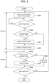
- FIG. 4 is a flowchart showing a control method concerning control of power supply to the servomotor 410 at the time when the autonomous mobile robot 1 moves among the work stations WS1, WS2, and WS0. Processing shown in FIG. 4 is executed mainly by the vehicle control section 740 of the vehicle 700, the operation control device 300 of the robot 100, and the vehicle allocation system 640 of the host management device 600 (see FIGS. 1 and 2 ).
- Processing for performing work in the work stations WS1, WS2, and WS0 with the autonomous mobile robot 1 is substantially divided into the following steps.
- a step for moving the vehicle 700 to the work station WS of the first type is represented as a step Sta (see the middle left part of FIG. 4 ).
- a step of moving the vehicle 700 to the work station WS of the second type is represented as a step Stc (see the middle left part of FIG. 4 ).
- a step of driving the robot arm in the work station WS of the first type is represented as a step Stb (see the lower left part of FIG. 4 ).
- a step of not driving the robot arm 110 in the work station WS of the second type and charging the autonomous mobile robot 1 is represented as a step Std (see the lower left part of FIG. 4 ).
- step S100 prior to the vehicle control section 740 of the vehicle 700 starting movement of the vehicle 700 to the next work station WS, the operation control device 300 of the robot 100 controls the robot arm 110 to a predetermined posture and stops supply of electric power to the servomotor 410 of the robot arm 110. As a result, excitation of the servomotor 410 is turned off. While the excitation of the servomotor 410 is off, the output shafts of the servomotors 410 of the robot arm 110 are held by the brakes included in the servomotors 410. As a result, the posture of the robot arm 110 is also held.
- the vehicle control section 740 starts movement of the vehicle 700 to the next work station WS.
- the vehicle 700 moves in a state in which electric power is not supplied to the servomotor 410 of the robot arm 110.
- step S200 the vehicle control section 740 determines whether a start condition for power supply to the servomotor 410 of the robot arm 110 is satisfied.
- the start condition is a condition concerning relative positions of the work station WS at a destination and the vehicle 700 moving along a route to the work station WS at the destination. Content of the start condition is explained below.
- step S200 When the start condition is not satisfied, the processing returns to step S200. When the start condition is satisfied, the processing proceeds to step S300.
- step S300 the operation control device 300 determines whether the work station WS at the next destination is the work station WS1 or WS2 of the first type in which the autonomous mobile robot 1 drives the robot arm 110 and performs work. Specifically, the operation control device 300 performs the determination based on information concerning a type of the work station WS at the next destination included in an instruction received from the host management device 600.
- step S500 When the work station WS at the next destination is not the work station WS1 or WS2 of the first type, that is, when the work station WS at the nest destination is the work station WS0 of the second type, the processing proceeds to step S500.
- the work station WS at the next destination is the work station WS1 or WS2 of the first type, the processing proceeds to step S400.
- step S400 the operation control device 300 starts supply of electric power to the servomotor 410 of the robot arm 110.
- the supply of electric power to the servomotor 410 is started during movement of the vehicle 700 in the state in which electric power is not supplied to the servomotor 410.
- a fixed time is required until the robot arm 110 can be driven after the supply of electric power to the servomotor 410 is started.
- step S500 the vehicle 700 arrives at the work station WS.
- step S500 the vehicle 700 is arranged in the work station WS1 or WS2 of the first type in a state in which electric power is supplied to the servomotor 410 of the robot arm 110.
- step 5500 not through step S400 the vehicle 700 is arranged in the work station WS0 of the second type in the state in which electric power is not supplied to the servomotor 410 of the robot arm 110.
- the vehicle 700 is moved to the work station WS0 of the second type in which the robot arm 110 is not driven, the vehicle 700 is moved in the state in which electric power is not supplied to the servomotor 410 of the robot arm 110 (see S100 and 5500 in FIG. 4 ). Accordingly, it is possible to reduce electric power consumed by the robot arm 110 compared with a form of supplying electric power to the servomotor 410 while the vehicle 700 is moved.
- the processing in steps S100 to 5500 is the steps Sta and Stc for moving the vehicle 700 to the work station WS.
- step S600 the operation control device 300 determines whether the work station WS at which the vehicle 700 arrives is the work station WS1 or WS2 of the first type. Specifically, the operation control device 300 performs the determination based on information concerning a type of the work station WS at the next destination included in an instruction received from the host management device 600.
- the vehicle control section 740 may store a determination result in step S300 in the RAM 742 and divert the determination result in step S300 as determination in step S600.
- step S800 When the work station WS at which the vehicle 700 arrives is not the work station WS1 or WS2 of the first type, that is, when the work station WS at which the vehicle 700 arrives is the work station WS0 of the second type, the processing proceeds to step S800.
- the work station WS at which the vehicle 700 arrives is the work station WS1 or WS2 of the first type, the processing proceeds to step S700.
- step S700 the operation control device 300 drives the robot arm 110 in the work station WS1 or WS2 of the first type and executes work (see the upper left part of FIG. 2 ).
- step S800 the operation control device 300 does not drive the robot arm 110 in the work station WS0 of the second type and stays on standby.
- the station control system WSCO of the work station WS0 charges the storage battery 750 of the autonomous mobile robot 1 with the charging device BtC (see the upper right part of FIG. 2 ).
- the processing in steps S600 to S800 is the steps Stb and Std. More specifically, the processing in step 5700 is the step Stb of driving the robot arm 110 in the work station WS of the first type. The processing in step 5800 is the step Std of not driving the robot arm 110 and charging the autonomous mobile robot 1 in the work station WS of the second type.
- step S900 the vehicle control section 740 of the vehicle 700 determines whether all processing that should be executed in the work stations WS1, WS2, and WS0 has ended. Specifically, the vehicle control section 740 of the vehicle 700 determines whether an instruction indicating that all the processing that the autonomous mobile robot 1 should execute in the work stations WS1, WS2, and WS0 has ended is received from the host management device 600 or whether an instruction of the work station WS to which the autonomous mobile robot 1 should move is received from the host management device 600.
- step S100 the operation control device 300 of the robot 100 stops the supply of electric power to the servomotor 410 of the robot arm 110.
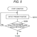
- FIG. 5 is a flowchart showing content of the determination processing for the start condition in step 5200 in FIG. 4 .
- the vehicle control section 740 detects a present position. More specifically, the vehicle control section 740 detects a present position of the vehicle 700 based on information acquired from the IMU 710 and the camera 720 (see 710 and 720 in FIG. 1 ).
- step S220 the vehicle control section 740 determines whether the present position is a position where power supply to the servomotor 410 should be started.
- Information concerning the position where power supply to the servomotor 410 should be started is stored in advance in the RAM 742 of the vehicle control section 740 together with information concerning a route for moving among the work stations WS1, WS2, and WS0 before movement to the work station WS at a destination is started.
- the information concerning the position where power supply to the servomotor 410 should be started can be, for example, information concerning a marker provided in the route for moving among the work stations WS1, WS2, and WS0.
- the vehicle control section 740 can determine that the present position is the position where power supply to the servomotor 410 should be started.
- the specific marker may not be provided.
- Components included in the work stations WS1, WS2, and WS0 and angles and sizes of the components photographed by a camera can be the information for specifying the position where power supply should be started.
- a position on the route that is, a position present at a distance L from the work station WS in the opposite direction of a traveling direction of the vehicle 700 moving to the work station WS can be set as the position where power supply to the servomotor 410 should be started.
- the size of the distance L can be decided in advance based on a time from when the supply of electric power to the servomotor 410 is started until the robot arm 110 changes to a state in which the robot arm 110 can start work and speed of the movement of the vehicle 700.
- step S210 When the present position is not the position where power supply to the servomotor 410 should be started, the processing returns to step S210.
- the processing proceeds to step S300.
- the supply of electric power to the servomotor 410 of the robot arm 110 is started (see S220 in FIG. 5 and 5200 to S400 in FIG. 4 ).
- the vehicle 700 in an operable state of the robot arm 110, it is possible to arrange the vehicle 700 in the work station WS1 or WS2 of the first type by appropriately setting the position where the supply of electric power should be started. Accordingly, it is unnecessary to hold off a start of work in the work station WS1 or WS2 of the first type until the robot arm 110 changes to the operable state.
- FIG. 6 is a chart showing exchange of commands among the AMR control system 620, the vehicle allocation system 640, the vehicle control section 740 of the vehicle 700, and the operation control device 300 of the robot 100 at the time when the processing is performed according to FIGS. 4 and 5 .
- the AMR control system 620 transmits a "Go to Cell A” command (see the upper left part of FIG. 6 ).
- the "Go to Cell A” command is received by the vehicle control section 740 through the vehicle allocation system 640.
- the operation control device 300 of the robot 100 stops the supply of electric power to the servomotor 410 of the robot arm 110.
- the vehicle control section 740 of the vehicle 700 starts movement of the vehicle 700 to the next work station WS1 represented by "A” (see S100 in FIG. 4 ). This processing is represented by "Move to Cell A" not surrounded by quotation marks in the upper right part of FIG. 6 .
- the operation control device 300 starts the supply of electric power to the servomotor 410 of the robot arm 110 (see steps S200 to S400 in FIG. 4 ).
- This processing is represented by an arrow of "Motor ON” in the middle right part of FIG. 6 .
- the position where power supply to the servomotor 410 should be started is represented by "Cell Position" in the upper right part of FIG. 6 (see S200 in FIG. 4 ).
- the work station WS1 represented by "A" in the "Go to Cell A” command is the work station of the first type in which the robot arm 110 is driven to perform work. Accordingly, the determination in step S300 in FIG. 4 is Yes. To facilitate understanding of the technique, the processing in step S300 in FIG. 4 is not shown in FIG. 6 .
- the vehicle control section 740 transmits an "Arrived" command (see the upper center of FIG. 6 and 5500 in FIG. 4 ).
- the "Arrived” command is received by the AMR control system 620 through the vehicle allocation system 640 as a "Done” command representing execution completion of a command.
- the AMR control system 620 transmits a "Pick Work-1" command (see the center of FIG. 6 ).
- the "Pick Work-1" command is received by the operation control device 300 of the robot 100 through the vehicle allocation system 640 and the vehicle control section 740.
- the operation control device 300 drives the robot arm 110 according to a robot control program and performs work in the work station WS1 (see S700 in FIG. 4 ). In the example shown in FIG. 6 , work for lifting the workpiece WP is executed. This processing is represented by "Robot Control Program "Pick"" in the middle right part of FIG. 6 .
- the operation control device 300 of the robot 100 transmits the "Done" command representing execution completion of a command (see the middle part of FIG. 6 ).
- the "Done” command is received by the AMR control system 620 through the vehicle control section 740 and the vehicle allocation system 640.
- the operation control device 300 of the robot 100 stops the supply of electric power to the servomotor 410 of the robot arm 110 (see S100 in FIG. 4 ). This processing is represented by an arrow of "OFF" in the middle right part of FIG. 6 .
- the AMR control system 620 transmits a command "Go to Cell B" (see the middle left part of FIG. 6 and S900 in FIG. 4 ).
- the command "Go to Cell B” is received by the vehicle control section 740 through the vehicle allocation system 640.
- the vehicle control section 740 of the vehicle 700 starts movement of the vehicle 700 to the next work station WS2 represented by "B” (see “Move to Cell B” in the lower right part of FIG. 6 and 5100 in FIG. 4 ).
- the operation control device 300 starts supply of electric power to the servomotor 410 of the robot arm 110 (see "Motor ON" in the lower right part of FIG. 6 and 5200 to S400 in FIG. 4 ).
- the vehicle control section 740 transmits the "Arrived" command (see the lower center of FIG. 6 and 5500 in FIG. 4 ).
- the "Arrived” command is received by the AMR control system 620 through the vehicle allocation system 640 as the "Done" command.
- the AMR control system 620 transmits a "Place Work-1" command (see the lower center of FIG. 6 ).
- the "Place Work-1" command is received by the operation control device 300 of the robot 100 through the vehicle allocation system 640 and the vehicle control section 740. Then, the operation control device 300 drives the robot arm 110 according to the robot control program and performs work in the work station WS2 (see S700 in FIG. 4 ). In the example shown in FIG. 6 , work for placing the gripped workpiece WP is executed in the work station WS1 (see "Robot Control Program "Place"" in the lower right part of FIG. 6 ).
- the operation control device 300 transmits the "Done” command (see the lower center of FIG. 6 ).
- the "Done” command is received by the AMR control system 620 through the vehicle control section 740 and the vehicle allocation system 640.
- the operation control device 300 of the robot 100 stops the supply of electric power to the servomotor 410 of the robot arm 110 ("OFF" in the lower right part of FIG. 6 and 5100 in FIG. 4 ).
- the vehicle 700 moves in the state in which electric power is not supplied to the servomotor 410 of the robot arm 110 ("Move to Cell A”, “Move to Cell B", and an arrow of "Motor ON” in the right part of FIG. 6 ). Accordingly, it is possible to reduce electric power consumed by the robot arm 110 compared with a form of continuously supplying electric power to the servomotor 410 of the robot arm 110 while the vehicle 700 is moved.
- the vehicle 700 is arranged in the work station WS1 or WS2 of the first type in the state in which electric power is supplied to the servomotor 410 of the robot arm 110 (see "Motor ON" in the right part of FIG. 6 ). Accordingly, it is possible to advance start timing of work in the work station WS1 or WS2 of the first type compared with a form of starting the supply of electric power to the servomotor 410 after the vehicle 700 arrives at the work station WS1 or WS2 of the first type.
- the robot arm 110 since electric power is not supplied to the servomotor 410 of the robot arm 110, even when the operation control device 300 malfunctions or noise is mixed in a command to the servomotor 410 of the robot arm 110, the robot arm 110 does not perform an unexpected movement and damage structures around the robot arm 110.
- the autonomous mobile robot 1 in this embodiment is referred to as “robot system” as well.
- the servomotor 410 is referred to as “electric motor” as well.
- the camera 720 and the vehicle control section 740 are referred to as “position detecting section” as well.
- the RAM 742 is referred to as "storing section” as well.
- the operation mode for moving the vehicle 700 in the state in which electric power is not supplied to the servomotor 410 (see S100 in FIG. 4 ), starting supply of electric power to the servomotor 410 during the movement of the vehicle 700 (see S400), and arranging the vehicle 700 in the work station WS1 or WS2 of the first type in the state in which electric power is supplied to the servomotor 410 (see S500) is referred to as "first operation mode" as well (see Sta in FIG. 4 ).
- the operation mode for moving the vehicle 700 in the state in which electric power is not supplied to the servomotor 410 (see S100) and arranging the vehicle 700 in the work station WS0 of the second type in the state in which electric power is not supplied to the servomotor 410 (see S500) is referred to as "second operation mode" as well (see Stc in FIG. 4 ).
- the processing leading to the supply of electric power to the servomotor 410 of the robot arm 110 is executed based on the determination result about whether the present position is the position where power supply to the servomotor 410 should be started (see S200 and 5400 in FIG. 4 and 5220 in FIG. 5 ).
- the determination about whether the start condition for power supply in S200 in FIG. 4 is satisfied can also be performed by other methods. In the following explanation, modifications of the method of determining whether the start condition for power supply is satisfied are explained.
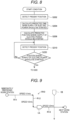
- FIG. 7 is a flowchart showing content of a modification 1 of the determination processing in step 5200 in FIG. 4 .
- the vehicle control section 740 detects a present position. Processing in step S210 in FIG. 7 is the same as the processing in step S210 in FIG. 5 .
- step S240 the vehicle control section 740 determines whether the present position is a position where measurement of an elapsed time should be started.
- Information concerning the position where measurement of an elapsed time should be started is stored in the RAM 742 of the vehicle control section 740 in advance together with the information concerning the route for moving among the work stations WS1, WS2, and WS0.
- the information concerning the position where measurement of an elapsed time should be started can be, for example, information concerning a marker provided in the route for moving among the work stations WS1, WS2, and WS0.
- the vehicle control section 740 can determine that the present position is the position where measurement of an elapsed time should be started.
- the specific marker may not be provided.
- Components included in the work stations WS1, WS2, and WS0 and angles and sizes of the components photographed by a camera can be the information concerning the position where power supply should be started.
- the position where measurement of an elapsed time should be started can be a position of the work station WS in which the vehicle 700 is arranged when the vehicle 700 starts movement.
- step S210 When the present position is not the position where measurement of an elapsed time should be started, the processing returns to step S210.
- the processing proceeds to step S250.
- step S250 the vehicle control section 740 starts measurement of an elapsed time. More specifically, measurement of time is performed by the CPU 741 of the vehicle control section 740. A functional section of the CPU 741 that measures time is shown in FIG. 1 as a timer 744.
- step S260 in FIG. 7 the vehicle control section 740 determines whether the elapsed time exceeds a threshold.
- Information concerning the threshold of the elapsed time is stored in the RAM 742 of the vehicle control section 740 in advance together with the information concerning the route for moving among the work stations WS1, WS2, and WS0.
- step S300 When the elapsed time does not exceed the threshold, the processing returns to step S260. When the elapsed time exceeds the threshold, the processing proceeds to step S300.
- the vehicle 700 can be arranged in the work station WS1 or WS2 of the first type in the operable state of the robot arm 110. Accordingly, it is unnecessary to hold off a start of work in the work station WS1 or WS2 of the first type until the robot arm 110 changes to the operable state.
- FIG. 8 is a flowchart showing content of a modification 2 of the determination processing in step 5200 in FIG. 4 .
- the processing in steps S202, 5204, and 5206 is executed prior to the processing in step S210 in FIG. 5 . Otherwise, the modification 2 of the start condition is the same as the first embodiment.
- step S202 the vehicle control section 740 detects a present position.
- the processing in step S202 in FIG. 8 is the same as the processing in step S210 in FIG. 5 .
- step S204 the vehicle control section 740 calculates, based on a route R10 on which the vehicle 700 moves to the work station WS of the first type at a destination and speed of the movement of the vehicle 700 on the route R10, time when the vehicle 700 arrives at the work station WS of the first type.
- FIG. 9 is an explanatory diagram showing speeds V1 to V3 of movement of the vehicle 700 designated in sections R11 to R12 of the route R10 on which the vehicle 700 moves to the work station WS of the first type.
- V1 m/s is designated as the speed of the movement of the vehicle 700.
- V2 m/s is designated as the speed of the movement of the vehicle 700.
- V3 m/s is designated as the speed of the movement of the vehicle 700.
- the vehicle control section 740 calculates, based on the route R10 on which the vehicle 700 moves to the work station WS of the first type at the destination and the time when the vehicle 700 arrives at the work station WS of the first type, predicted time going back from arrival time by a preparation time sufficient from when the supply of electric power to the servomotor 410 is started until the robot arm 110 changes to a state in which the robot arm 110 can start work.
- the predicted time obtained by the processing in step S204 is predicted time when the supply of electric power to the servomotor 410 should be started.
- the vehicle control section 740 stores the obtained predicted time in the RAM 742.
- step S206 the vehicle control section 740 calculates, based on the route R10 on which the vehicle 700 moves to the work station WS of the first type at the destination and the predicted time, a predicted position on the route R10 where the vehicle 700 is located at the predicted time.
- the vehicle control section 740 stores the obtained predicted position in the RAM 742 as a position where power supply to the servomotor 410 should be started.
- Information concerning the predicted position can be various kinds of information as explained in the processing in step S220 in FIG. 5 .
- Various predicted positions can be specified by changing sizes and angles at the time when the marker and the components included in the work stations WS1, WS2, and WS0 are photographed by the camera 720.
- step S210 the vehicle control section 740 detects a present position.
- the processing in step S210 in FIG. 8 is the same as the processing in step S210 in FIG. 5 .
- step S220 the vehicle control section 740 determines whether the present position is a position where power supply to the servomotor 410 should be started.
- the processing in step S220 in FIG. 8 is the same as the processing in step S220 in FIG. 5 .
- the position where power supply to the servomotor 410 should be started is the predicted position calculated in step S206.
- the subsequent processing is the same as the processing in the first embodiment (see S220 and subsequent steps in FIG. 4 and 5200 and subsequent steps in FIG. 5 ).
- the vehicle 700 can be arranged in the work station WS1 or WS2 of the first type in the operable state of the robot arm 110. Accordingly, it is possible to reduce likelihood that a start of work is held off in the work station WS1 or WS2 of the first type until the robot arm 110 changes to the operable state.
- FIG. 10 is a flowchart showing content of a modification 3 of the determination processing in step 5200 in FIG. 4 .
- the processing in step S208 is executed between step S206 and step S210 in FIG. 8 .
- the modification 3 of the start condition is the same as the modification 2 of the first embodiment.
- step S208 the vehicle control section 740 determines whether present time is the predicted time obtained in step S204.
- the predicted time obtained in step S204 is predicted time when supply of electric power to the servomotor 410 should be started.
- the processing returns to step S208.
- the processing proceeds to step S210.
- the subsequent processing is the same as the processing in the modification 2.
- the vehicle 700 can be arranged in the work station WS1 or WS2 of the first type in the operable state of the robot arm 110. Accordingly, it is possible to reduce likelihood that a start of work is held off in the work station WS1 or WS2 of the first type until the robot arm 110 changes to the operable state.
- the autonomous mobile robot 1 when routes of a plurality of autonomous mobile robots 1 cross, one autonomous mobile robot 1 stays on standby in a position before a crossing point on the routes until the other autonomous mobile robot 1 passes the crossing point.
- the autonomous mobile robot 1 on standby is shown as an autonomous mobile robot 1A.
- the autonomous mobile robot 1 passing the crossing point first is shown as an autonomous mobile robot 1B.
- the autonomous mobile robot 1 reaches the predicted position obtained in step S206 at the predicted time obtained in step S204 in some cases and does not reach the predicted position yet in other cases.
- the autonomous mobile robot 1 has not already passed the predicted position obtained in step S206 at the predicted time obtained in step S204.
- the recognition and the determination of the present position are executed after the present time reaches the predicted time obtained in step S204 (see S208 to 5220 in FIG. 10 ). Accordingly, electric power is not supplied to the servomotor 410 of the robot arm 110 in spite of the fact that the autonomous mobile robot 1 does not reach the predicted position obtained in step S206 yet. Accordingly, compared with the modification 1, it is possible to reduce power consumption of the robot arm 110.
- the recognition and the determination of the present position is not executed until the present time reaches the predicted time obtained in step S204 (see S210 and 5220 in FIG. 10 ). Accordingly, the number of times of repetition of the recognition and the determination of the present position, which requires a processing load larger than a processing load in the processing in step S208 for measuring a time, is smaller than the number of times in the modification 2. Accordingly, it is possible to reduce a processing load of the vehicle control section 740 compared with the modification 2.
- the processing for stopping the supply of electric power to the servomotor 410 of the robot arm 110 prior to the start of the movement of the vehicle 700 is not performed depending on a case (see S100 in FIG. 4 ). Otherwise, the second embodiment is the same as the first embodiment.
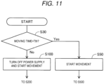
- FIG. 11 is a flowchart showing processing concerning control of power supply to the servomotor 410 at the time the autonomous mobile robot 1 moves among the work stations WS1, WS2, and WS0.
- determination processing in step S30 is performed prior to the processing in step S100 in FIG. 4 .
- the processing in steps S100 to S400 is performed as in the first embodiment or the processing in steps S100 to S400 is skipped and the processing in step S500 is performed.
- the processing concerning control of power supply to the servomotor 410 shown in FIG. 11 is the same as the processing concerning control of power supply to the servomotor 410 shown in FIG. 4 .
- step S30 the vehicle control section 740 of the vehicle 700 calculates, based on a route on which the vehicle 700 moves to the work station WS at the next destination and speed of the movement of the vehicle 700 on the route, a moving time required for the movement to the work station WS at the next destination.
- the vehicle control section 740 determines whether the moving time is shorter than a predetermined time threshold Tth.
- step S100 When the moving time is not shorter than the predetermined time threshold Tth, the processing proceeds to step S100.
- the processing proceeds to step S50.
- step S50 the vehicle control section 740 of the vehicle 700 starts movement of the vehicle 700 to the next work station WS.
- step S50 the operation control device 300 of the robot 100 does no stop the supply of electric power to the servomotor 410 of the robot arm 110 prior to the start of the movement.
- step 550 the processing proceeds to step S500.
- step S50 the vehicle 700 moves in a state in which electric power is supplied to the servomotor 410 of the robot arm 110.
- the vehicle 700 is arranged in the work station WS in the state in which electric power is supplied to the servomotor 410 of the robot arm 110 (see S50 in FIG. 11 and 5500 in FIG. 4 ).
- the vehicle can be a vehicle including an ultrasonic sensor and a laser sensor.
- the position of the vehicle may be detected based on those sensors.
- Various sensors used for position detection of the vehicle such as a camera, an ultrasonic sensor, and a laser sensor may be attached to a robot or may be provided in an immobile structure other than the vehicle.
- the autonomous mobile robot 1 may perform processing in the case in which the target work station WS is the work station of the first type.
- the determination about whether the next work station WS is the work station of the first type may be performed first. Thereafter, division of the processing may be performed using a result of the determination. For example, the processing in the second embodiment may be performed, after such determination, only when the next station WS is the work station of the first type (see S30 and S50 in FIG. 11 ).
- the power supply conditions including the condition that the position of the vehicle 700 reaches the position where the supply of electric power should be started are satisfied during the movement of the vehicle 700
- the supply of electric power to the servomotor 410 of the robot arm 110 is started (see S220 in FIG. 5 and 5200 to S400 in FIG. 4 ).
- the power supply conditions can be other conditions as explained in the modifications of the first embodiment (see FIGS. 7 to 10 ).
- the determination of the power supply conditions is not limited to the CPU 741 of the vehicle control section 740 and may be performed by another processor such as the CPU 601 of the host management device 600.
- the power supply conditions including the condition that the elapsed time from when the vehicle 700 passes the position where the measurement of an elapsed time should be started exceeds the threshold are satisfied during the movement of the vehicle 700
- the supply of electric power to the servomotor 410 of the robot arm 110 is started (see S240 and S260 in FIG. 7 and 5200 to S400 in FIG. 4 ).
- the power supply conditions can also be other conditions as explained in the first embodiment and the other modifications of the first embodiment (see FIGS. 7 to 10 ).
- the predetermined condition for starting the measurement of an elapsed time can also be other conditions such as a condition that a state of a hard switch provided in a vehicle changes and a condition that a state of a hard switch provided in a component other than the vehicle changes.
- a condition that the intensity of a radio wave received by a device, which is provided in the vehicle and receives the radio wave, is equal to or higher than a threshold can also be the predetermined condition for staring the measurement of an elapsed time.
- condition for starting the measurement of an elapsed time is not limited to the condition concerning a place where the vehicle is located and can also be other conditions.
- condition for starting the measurement of an elapsed time can also be a condition concerning a state of the autonomous mobile robot 1 and a state of the work station WS (see S210 and S240 in FIG. 7 ).
- the processing in steps S200 to S400 in FIG. 4 is not performed (see S30 and S50 in FIG. 11 ).
- a form can also be adopted in which such processing is not performed and the processing in steps S200 to S400 in FIG. 4 is always performed irrespective of the moving time required for movement to the work station WS at the next destination.
- step 5400 when the work station WS at the next destination is the work station WS0 of the second type, the processing in step 5400 is not performed and the processing proceeds to step S500 (see S300 in FIG. 4 ).
- a form can also be adopted in which the supply of electric power to the electric motor of the robot arm is started irrespective of a type of the work station WS at the next destination.
- a control method for a robot system includes: a robot arm driven by an electric motor; and a vehicle that is movable and supports the robot arm.
- the control method includes: (a) a step of moving the vehicle to a work station of a first type; and (b) a step of driving the robot arm in the work station of the first type.
- the step (a) executes a first operation mode for, in a part of the movement to the work station of the first type, moving the vehicle in a state in which electric power is not supplied to the electric motor, starting supply of the electric power to the electric motor during the movement of the vehicle in the state in which the electric power is not supplied to the electric motor, and arranging the vehicle in the work station of the first type in a state in which the electric power is supplied to the electric motor.
- the robot system may include: a position detecting section configured to detect a position of the vehicle; and a storing section storing information concerning a position where the supply of the electric power to the electric motor should be started.
- the step (a) may include, in the first operation mode, a step of starting the supply of the electric power to the electric motor when power supply conditions including a condition that the position of the vehicle reaches the position where the supply of the electric power should be started are satisfied during the movement of the vehicle.
- the robot system may include: a timer that can measure a time; and a storing section storing information concerning a threshold of an elapsed time.
- the step (a) may include, in the first operation mode, a step of starting the supply of the electric power to the electric motor when power supply conditions including a condition that an elapsed time from when a predetermined condition is satisfied exceeds the threshold are satisfied during the movement of the vehicle.
- the robot system may include a position detecting section configured to detect a position of the vehicle.
- the step (a) may include, in the first operation mode: a step of calculating, based on a route on which the vehicle moves to the work station of the first type and speed of the movement of the vehicle on the route, a predicted position on the route where the vehicle is located at predicted time going back, by a preparation time from when the supply of the electric power to the electric motor is started until the robot arm changes to a state in which the robot arm can start work, from time when the vehicle arrives at the work station of the first type; and a step of starting the supply of the electric power to the electric motor when power supply conditions including a condition that the position of the vehicle reaches the predicted position are satisfied during the movement of the vehicle.
- the robot system may include a timer that can measure a time.
- the step (a) may include, in the first operation mode: a step of calculating, based on a route on which the vehicle moves to the work station of the first type and speed of the movement of the vehicle on the route, predicted time going back, by a time from when the supply of the electric power to the electric motor is started until the robot arm changes to a state in which the robot arm can start work, from time when the vehicle arrives at the work station of the first type; and a step of starting the supply of the electric power to the electric motor when power supply conditions including a condition that present time reaches the predicted time are satisfied during the movement of the vehicle.
- the step (a) may execute the first operation mode executed when a time required for the movement to the work station of the first type is equal to or longer than a predetermined threshold, the first operation mode being for moving the vehicle in the state in which the electric power is not supplied to the electric motor and arranging the vehicle in the work station of the first type in the state in which the electric power is supplied to the electric motor.
- control method may further include: (c) a step of moving the vehicle to a work station of a second type; and (d) a step of performing processing concerning the robot system without driving the robot arm in the work station of the second type.
- the step (c) may execute a second operation mode for moving the vehicle in the state in which the electric power is not supplied to the electric motor and arranging the vehicle in the work station of the second type in the state in which the electric power is not supplied to the electric motor.
- the present disclosure can also be realized in various forms other than the control method for the robot system.
- the present disclosure can be realized in forms of the robot system, a computer program for realizing the control method for the robot system, and a non-transitory recording medium recording the computer program.
Landscapes
- Engineering & Computer Science (AREA)
- Robotics (AREA)
- Mechanical Engineering (AREA)
- General Health & Medical Sciences (AREA)
- Orthopedic Medicine & Surgery (AREA)
- Health & Medical Sciences (AREA)
- Automation & Control Theory (AREA)
- Human Computer Interaction (AREA)
- General Engineering & Computer Science (AREA)
- Manufacturing & Machinery (AREA)
- Quality & Reliability (AREA)
- Physics & Mathematics (AREA)
- General Physics & Mathematics (AREA)
- Manipulator (AREA)
- Control Of Position, Course, Altitude, Or Attitude Of Moving Bodies (AREA)
Applications Claiming Priority (1)
| Application Number | Priority Date | Filing Date | Title |
|---|---|---|---|
| JP2019216058A JP7392428B2 (ja) | 2019-11-29 | 2019-11-29 | ロボットシステムの制御方法 |
Publications (2)
| Publication Number | Publication Date |
|---|---|
| EP3827936A1 EP3827936A1 (en) | 2021-06-02 |
| EP3827936B1 true EP3827936B1 (en) | 2024-03-27 |
Family
ID=73475886
Family Applications (1)
| Application Number | Title | Priority Date | Filing Date |
|---|---|---|---|
| EP20208180.8A Active EP3827936B1 (en) | 2019-11-29 | 2020-11-17 | Control method for robot system |
Country Status (5)
| Country | Link |
|---|---|
| US (1) | US11633851B2 (https=) |
| EP (1) | EP3827936B1 (https=) |
| JP (1) | JP7392428B2 (https=) |
| CN (1) | CN112873198B (https=) |
| TW (1) | TWI755947B (https=) |
Families Citing this family (4)
| Publication number | Priority date | Publication date | Assignee | Title |
|---|---|---|---|---|
| CN116833996A (zh) * | 2022-03-25 | 2023-10-03 | 美的集团股份有限公司 | 工业机器人的控制方法、设备及存储介质 |
| US20250229416A1 (en) * | 2022-04-01 | 2025-07-17 | Vanderbilt University | Inertia-based improvements to robots and robotic systems |
| WO2024142800A1 (ja) * | 2022-12-29 | 2024-07-04 | パナソニックIpマネジメント株式会社 | 搬送制御システム、搬送システム、及び搬送制御システムの制御方法 |
| DE102024130167A1 (de) * | 2024-10-17 | 2026-04-23 | Kuka Deutschland Gmbh | Verfahren zum Betreiben einer automatisierten Produktionsanlage, automatisiertes Arbeitssystem und Computerprogrammprodukt |
Family Cites Families (18)
| Publication number | Priority date | Publication date | Assignee | Title |
|---|---|---|---|---|
| JPH01115580A (ja) * | 1987-10-28 | 1989-05-08 | Mitsubishi Electric Corp | マニピュレータ付搬送車のマニピュレータ保持装置 |
| JPH04240078A (ja) * | 1991-01-22 | 1992-08-27 | Sony Corp | ロボットを搭載した搬送車及びこれを用いる生産装置 |
| JP4491912B2 (ja) * | 2000-05-22 | 2010-06-30 | ソニー株式会社 | バッテリ駆動の脚式移動ロボット及びその制御方法 |
| EP2112963B1 (en) * | 2006-10-06 | 2018-05-30 | iRobot Defense Holdings, Inc. | Robotic vehicle with tracks and flippers |
| JP2008260117A (ja) | 2007-03-16 | 2008-10-30 | Nsk Ltd | 脚車輪型ロボット及び脚車輪装置 |
| JP6474339B2 (ja) * | 2015-09-01 | 2019-02-27 | ファナック株式会社 | ブレーキの異常による駆動軸における部材の移動を停止する機械 |
| JP2017132002A (ja) * | 2016-01-28 | 2017-08-03 | 株式会社安川電機 | ロボットアーム付自動搬送車、ロボットシステム、及びロボットアーム付自動搬送車の制御方法 |
| CN105643589B (zh) * | 2016-03-08 | 2018-08-07 | 北京工业大学 | 一种自主排障式智能车系统 |
| CN107305372B (zh) * | 2016-04-25 | 2020-06-19 | 岳秀兰 | 云计算网络架构的远程监控的电动汽车能源监控和补给网 |
| CN106043247B (zh) * | 2016-06-23 | 2020-02-28 | 蔚来汽车有限公司 | 模块化可扩充的换电站设备和充电架 |
| JP2018075672A (ja) * | 2016-11-10 | 2018-05-17 | セイコーエプソン株式会社 | 制御装置、ロボットおよびロボットシステム |
| JP6818565B2 (ja) * | 2017-01-24 | 2021-01-20 | 三菱重工エンジン&ターボチャージャ株式会社 | 生産システム |
| JP6585656B2 (ja) * | 2017-05-10 | 2019-10-02 | 株式会社ソニー・インタラクティブエンタテインメント | 製造ライン用コンピュータシステム及びそのネットワーク設定方法 |
| US10916073B2 (en) * | 2018-05-01 | 2021-02-09 | Ford Global Technologies, Llc | Vehicle network data streaming system |
| JP2019216058A (ja) | 2018-06-14 | 2019-12-19 | 日本電子株式会社 | 電子顕微鏡および評価方法 |
| CN208756849U (zh) * | 2018-06-20 | 2019-04-19 | 南阳防爆电气研究所有限公司 | 一种消防灭火侦察防爆机器人 |
| JP7131131B2 (ja) * | 2018-06-29 | 2022-09-06 | マツダ株式会社 | 車両用ライン検出装置および該方法 |
| CN209140881U (zh) * | 2018-09-12 | 2019-07-23 | 珠海心怡科技有限公司 | 通用型建筑室内工程智能机器人 |
-
2019
- 2019-11-29 JP JP2019216058A patent/JP7392428B2/ja active Active
-
2020
- 2020-11-17 EP EP20208180.8A patent/EP3827936B1/en active Active
- 2020-11-25 CN CN202011339123.XA patent/CN112873198B/zh active Active
- 2020-11-25 US US17/104,211 patent/US11633851B2/en active Active
- 2020-11-26 TW TW109141624A patent/TWI755947B/zh active
Also Published As
| Publication number | Publication date |
|---|---|
| JP2021084195A (ja) | 2021-06-03 |
| CN112873198B (zh) | 2023-05-23 |
| EP3827936A1 (en) | 2021-06-02 |
| TWI755947B (zh) | 2022-02-21 |
| US20210162591A1 (en) | 2021-06-03 |
| TW202120273A (zh) | 2021-06-01 |
| CN112873198A (zh) | 2021-06-01 |
| US11633851B2 (en) | 2023-04-25 |
| JP7392428B2 (ja) | 2023-12-06 |
Similar Documents
| Publication | Publication Date | Title |
|---|---|---|
| EP3827936B1 (en) | Control method for robot system | |
| US9452532B2 (en) | Robot, device and method for controlling robot, and computer-readable non-transitory recording medium | |
| EP2925494B1 (en) | Teleoperation of machines having at least one actuated mechanism and one machine controller comprising a program code including instructions for transferring control of the machine from said controller to a remote control station | |
| JP6268819B2 (ja) | 多軸型ロボットの軌道生成方法 | |
| JP7275488B2 (ja) | ロボットシステム | |
| JP4544145B2 (ja) | ロボットの干渉回避方法およびロボット | |
| US20230234229A1 (en) | Systems and methods of coordinated body motion of robotic devices | |
| US20200130200A1 (en) | Control Apparatus And Robot System | |
| EP2230054A1 (en) | Robot movement regulating method, robot system, and robot movement regulating device | |
| US10960553B2 (en) | Robot control device and robot system | |
| US20150039129A1 (en) | Robot system and product manufacturing method | |
| US11040449B2 (en) | Robot control system and method of controlling a robot | |
| EP1901151A1 (en) | A method and a device for avoiding collisions between an industrial robot and an object | |
| US11141862B2 (en) | Control apparatus, robot system and control method | |
| JPH07271415A (ja) | 協調ロボット制御方法 | |
| US20210146542A1 (en) | Control method for robot system | |
| US20210268651A1 (en) | Robot control method | |
| US12370670B2 (en) | Dual-arm robot system | |
| JP2019104091A (ja) | ロボット装置、ロボット装置の制御方法 | |
| WO2024045091A1 (zh) | 执行机构的运动规划方法、装置、系统及存储介质 | |
| EP4434689A1 (en) | Control method, robot system, and non-transitory computer-readable storage medium storing program | |
| CN112135718A (zh) | 机器人的控制 | |
| JP7384005B2 (ja) | 制御方法およびロボットシステム | |
| WO2021235141A1 (ja) | 移動体及びその制御装置、方法及びプログラム | |
| CN116766206A (zh) | 力位混合的长桁零件机器人自动敷设方法、装置及设备 |
Legal Events
| Date | Code | Title | Description |
|---|---|---|---|
| PUAI | Public reference made under article 153(3) epc to a published international application that has entered the european phase |
Free format text: ORIGINAL CODE: 0009012 |
|
| STAA | Information on the status of an ep patent application or granted ep patent |
Free format text: STATUS: THE APPLICATION HAS BEEN PUBLISHED |
|
| AK | Designated contracting states |
Kind code of ref document: A1 Designated state(s): AL AT BE BG CH CY CZ DE DK EE ES FI FR GB GR HR HU IE IS IT LI LT LU LV MC MK MT NL NO PL PT RO RS SE SI SK SM TR |
|
| STAA | Information on the status of an ep patent application or granted ep patent |
Free format text: STATUS: REQUEST FOR EXAMINATION WAS MADE |
|
| 17P | Request for examination filed |
Effective date: 20211202 |
|
| RBV | Designated contracting states (corrected) |
Designated state(s): AL AT BE BG CH CY CZ DE DK EE ES FI FR GB GR HR HU IE IS IT LI LT LU LV MC MK MT NL NO PL PT RO RS SE SI SK SM TR |
|
| STAA | Information on the status of an ep patent application or granted ep patent |
Free format text: STATUS: EXAMINATION IS IN PROGRESS |
|
| 17Q | First examination report despatched |
Effective date: 20230227 |
|
| GRAP | Despatch of communication of intention to grant a patent |
Free format text: ORIGINAL CODE: EPIDOSNIGR1 |
|
| STAA | Information on the status of an ep patent application or granted ep patent |
Free format text: STATUS: GRANT OF PATENT IS INTENDED |
|
| INTG | Intention to grant announced |
Effective date: 20231024 |
|
| GRAS | Grant fee paid |
Free format text: ORIGINAL CODE: EPIDOSNIGR3 |
|
| GRAA | (expected) grant |
Free format text: ORIGINAL CODE: 0009210 |
|
| STAA | Information on the status of an ep patent application or granted ep patent |
Free format text: STATUS: THE PATENT HAS BEEN GRANTED |
|
| AK | Designated contracting states |
Kind code of ref document: B1 Designated state(s): AL AT BE BG CH CY CZ DE DK EE ES FI FR GB GR HR HU IE IS IT LI LT LU LV MC MK MT NL NO PL PT RO RS SE SI SK SM TR |
|
| REG | Reference to a national code |
Ref country code: GB Ref legal event code: FG4D |
|
| REG | Reference to a national code |
Ref country code: CH Ref legal event code: EP |
|
| REG | Reference to a national code |
Ref country code: DE Ref legal event code: R096 Ref document number: 602020027844 Country of ref document: DE |
|
| REG | Reference to a national code |
Ref country code: IE Ref legal event code: FG4D |
|
| PG25 | Lapsed in a contracting state [announced via postgrant information from national office to epo] |
Ref country code: LT Free format text: LAPSE BECAUSE OF FAILURE TO SUBMIT A TRANSLATION OF THE DESCRIPTION OR TO PAY THE FEE WITHIN THE PRESCRIBED TIME-LIMIT Effective date: 20240327 |
|
| REG | Reference to a national code |
Ref country code: LT Ref legal event code: MG9D |
|
| PG25 | Lapsed in a contracting state [announced via postgrant information from national office to epo] |
Ref country code: GR Free format text: LAPSE BECAUSE OF FAILURE TO SUBMIT A TRANSLATION OF THE DESCRIPTION OR TO PAY THE FEE WITHIN THE PRESCRIBED TIME-LIMIT Effective date: 20240628 |
|
| PG25 | Lapsed in a contracting state [announced via postgrant information from national office to epo] |
Ref country code: RS Free format text: LAPSE BECAUSE OF FAILURE TO SUBMIT A TRANSLATION OF THE DESCRIPTION OR TO PAY THE FEE WITHIN THE PRESCRIBED TIME-LIMIT Effective date: 20240627 Ref country code: HR Free format text: LAPSE BECAUSE OF FAILURE TO SUBMIT A TRANSLATION OF THE DESCRIPTION OR TO PAY THE FEE WITHIN THE PRESCRIBED TIME-LIMIT Effective date: 20240327 |
|
| PG25 | Lapsed in a contracting state [announced via postgrant information from national office to epo] |
Ref country code: RS Free format text: LAPSE BECAUSE OF FAILURE TO SUBMIT A TRANSLATION OF THE DESCRIPTION OR TO PAY THE FEE WITHIN THE PRESCRIBED TIME-LIMIT Effective date: 20240627 Ref country code: NO Free format text: LAPSE BECAUSE OF FAILURE TO SUBMIT A TRANSLATION OF THE DESCRIPTION OR TO PAY THE FEE WITHIN THE PRESCRIBED TIME-LIMIT Effective date: 20240627 Ref country code: LT Free format text: LAPSE BECAUSE OF FAILURE TO SUBMIT A TRANSLATION OF THE DESCRIPTION OR TO PAY THE FEE WITHIN THE PRESCRIBED TIME-LIMIT Effective date: 20240327 Ref country code: HR Free format text: LAPSE BECAUSE OF FAILURE TO SUBMIT A TRANSLATION OF THE DESCRIPTION OR TO PAY THE FEE WITHIN THE PRESCRIBED TIME-LIMIT Effective date: 20240327 Ref country code: GR Free format text: LAPSE BECAUSE OF FAILURE TO SUBMIT A TRANSLATION OF THE DESCRIPTION OR TO PAY THE FEE WITHIN THE PRESCRIBED TIME-LIMIT Effective date: 20240628 Ref country code: FI Free format text: LAPSE BECAUSE OF FAILURE TO SUBMIT A TRANSLATION OF THE DESCRIPTION OR TO PAY THE FEE WITHIN THE PRESCRIBED TIME-LIMIT Effective date: 20240327 Ref country code: BG Free format text: LAPSE BECAUSE OF FAILURE TO SUBMIT A TRANSLATION OF THE DESCRIPTION OR TO PAY THE FEE WITHIN THE PRESCRIBED TIME-LIMIT Effective date: 20240327 |
|
| REG | Reference to a national code |
Ref country code: NL Ref legal event code: MP Effective date: 20240327 |
|
| PG25 | Lapsed in a contracting state [announced via postgrant information from national office to epo] |
Ref country code: SE Free format text: LAPSE BECAUSE OF FAILURE TO SUBMIT A TRANSLATION OF THE DESCRIPTION OR TO PAY THE FEE WITHIN THE PRESCRIBED TIME-LIMIT Effective date: 20240327 Ref country code: LV Free format text: LAPSE BECAUSE OF FAILURE TO SUBMIT A TRANSLATION OF THE DESCRIPTION OR TO PAY THE FEE WITHIN THE PRESCRIBED TIME-LIMIT Effective date: 20240327 |
|
| PG25 | Lapsed in a contracting state [announced via postgrant information from national office to epo] |
Ref country code: NL Free format text: LAPSE BECAUSE OF FAILURE TO SUBMIT A TRANSLATION OF THE DESCRIPTION OR TO PAY THE FEE WITHIN THE PRESCRIBED TIME-LIMIT Effective date: 20240327 |
|
| REG | Reference to a national code |
Ref country code: AT Ref legal event code: MK05 Ref document number: 1669484 Country of ref document: AT Kind code of ref document: T Effective date: 20240327 |
|
| PG25 | Lapsed in a contracting state [announced via postgrant information from national office to epo] |
Ref country code: NL Free format text: LAPSE BECAUSE OF FAILURE TO SUBMIT A TRANSLATION OF THE DESCRIPTION OR TO PAY THE FEE WITHIN THE PRESCRIBED TIME-LIMIT Effective date: 20240327 |
|
| PG25 | Lapsed in a contracting state [announced via postgrant information from national office to epo] |
Ref country code: IS Free format text: LAPSE BECAUSE OF FAILURE TO SUBMIT A TRANSLATION OF THE DESCRIPTION OR TO PAY THE FEE WITHIN THE PRESCRIBED TIME-LIMIT Effective date: 20240727 |
|
| PG25 | Lapsed in a contracting state [announced via postgrant information from national office to epo] |
Ref country code: PT Free format text: LAPSE BECAUSE OF FAILURE TO SUBMIT A TRANSLATION OF THE DESCRIPTION OR TO PAY THE FEE WITHIN THE PRESCRIBED TIME-LIMIT Effective date: 20240729 Ref country code: SM Free format text: LAPSE BECAUSE OF FAILURE TO SUBMIT A TRANSLATION OF THE DESCRIPTION OR TO PAY THE FEE WITHIN THE PRESCRIBED TIME-LIMIT Effective date: 20240327 |
|
| PG25 | Lapsed in a contracting state [announced via postgrant information from national office to epo] |
Ref country code: ES Free format text: LAPSE BECAUSE OF FAILURE TO SUBMIT A TRANSLATION OF THE DESCRIPTION OR TO PAY THE FEE WITHIN THE PRESCRIBED TIME-LIMIT Effective date: 20240327 |
|
| PG25 | Lapsed in a contracting state [announced via postgrant information from national office to epo] |
Ref country code: EE Free format text: LAPSE BECAUSE OF FAILURE TO SUBMIT A TRANSLATION OF THE DESCRIPTION OR TO PAY THE FEE WITHIN THE PRESCRIBED TIME-LIMIT Effective date: 20240327 Ref country code: CZ Free format text: LAPSE BECAUSE OF FAILURE TO SUBMIT A TRANSLATION OF THE DESCRIPTION OR TO PAY THE FEE WITHIN THE PRESCRIBED TIME-LIMIT Effective date: 20240327 |
|
| PG25 | Lapsed in a contracting state [announced via postgrant information from national office to epo] |
Ref country code: AT Free format text: LAPSE BECAUSE OF FAILURE TO SUBMIT A TRANSLATION OF THE DESCRIPTION OR TO PAY THE FEE WITHIN THE PRESCRIBED TIME-LIMIT Effective date: 20240327 |
|
| PG25 | Lapsed in a contracting state [announced via postgrant information from national office to epo] |
Ref country code: PL Free format text: LAPSE BECAUSE OF FAILURE TO SUBMIT A TRANSLATION OF THE DESCRIPTION OR TO PAY THE FEE WITHIN THE PRESCRIBED TIME-LIMIT Effective date: 20240327 |
|
| PG25 | Lapsed in a contracting state [announced via postgrant information from national office to epo] |
Ref country code: SK Free format text: LAPSE BECAUSE OF FAILURE TO SUBMIT A TRANSLATION OF THE DESCRIPTION OR TO PAY THE FEE WITHIN THE PRESCRIBED TIME-LIMIT Effective date: 20240327 |
|
| PG25 | Lapsed in a contracting state [announced via postgrant information from national office to epo] |
Ref country code: SM Free format text: LAPSE BECAUSE OF FAILURE TO SUBMIT A TRANSLATION OF THE DESCRIPTION OR TO PAY THE FEE WITHIN THE PRESCRIBED TIME-LIMIT Effective date: 20240327 Ref country code: SK Free format text: LAPSE BECAUSE OF FAILURE TO SUBMIT A TRANSLATION OF THE DESCRIPTION OR TO PAY THE FEE WITHIN THE PRESCRIBED TIME-LIMIT Effective date: 20240327 Ref country code: RO Free format text: LAPSE BECAUSE OF FAILURE TO SUBMIT A TRANSLATION OF THE DESCRIPTION OR TO PAY THE FEE WITHIN THE PRESCRIBED TIME-LIMIT Effective date: 20240327 Ref country code: PT Free format text: LAPSE BECAUSE OF FAILURE TO SUBMIT A TRANSLATION OF THE DESCRIPTION OR TO PAY THE FEE WITHIN THE PRESCRIBED TIME-LIMIT Effective date: 20240729 Ref country code: PL Free format text: LAPSE BECAUSE OF FAILURE TO SUBMIT A TRANSLATION OF THE DESCRIPTION OR TO PAY THE FEE WITHIN THE PRESCRIBED TIME-LIMIT Effective date: 20240327 Ref country code: IS Free format text: LAPSE BECAUSE OF FAILURE TO SUBMIT A TRANSLATION OF THE DESCRIPTION OR TO PAY THE FEE WITHIN THE PRESCRIBED TIME-LIMIT Effective date: 20240727 Ref country code: ES Free format text: LAPSE BECAUSE OF FAILURE TO SUBMIT A TRANSLATION OF THE DESCRIPTION OR TO PAY THE FEE WITHIN THE PRESCRIBED TIME-LIMIT Effective date: 20240327 Ref country code: EE Free format text: LAPSE BECAUSE OF FAILURE TO SUBMIT A TRANSLATION OF THE DESCRIPTION OR TO PAY THE FEE WITHIN THE PRESCRIBED TIME-LIMIT Effective date: 20240327 Ref country code: CZ Free format text: LAPSE BECAUSE OF FAILURE TO SUBMIT A TRANSLATION OF THE DESCRIPTION OR TO PAY THE FEE WITHIN THE PRESCRIBED TIME-LIMIT Effective date: 20240327 Ref country code: AT Free format text: LAPSE BECAUSE OF FAILURE TO SUBMIT A TRANSLATION OF THE DESCRIPTION OR TO PAY THE FEE WITHIN THE PRESCRIBED TIME-LIMIT Effective date: 20240327 |
|
| PG25 | Lapsed in a contracting state [announced via postgrant information from national office to epo] |
Ref country code: IT Free format text: LAPSE BECAUSE OF FAILURE TO SUBMIT A TRANSLATION OF THE DESCRIPTION OR TO PAY THE FEE WITHIN THE PRESCRIBED TIME-LIMIT Effective date: 20240327 |
|
| PG25 | Lapsed in a contracting state [announced via postgrant information from national office to epo] |
Ref country code: IT Free format text: LAPSE BECAUSE OF FAILURE TO SUBMIT A TRANSLATION OF THE DESCRIPTION OR TO PAY THE FEE WITHIN THE PRESCRIBED TIME-LIMIT Effective date: 20240327 |
|
| REG | Reference to a national code |
Ref country code: DE Ref legal event code: R097 Ref document number: 602020027844 Country of ref document: DE |
|
| PG25 | Lapsed in a contracting state [announced via postgrant information from national office to epo] |
Ref country code: DK Free format text: LAPSE BECAUSE OF FAILURE TO SUBMIT A TRANSLATION OF THE DESCRIPTION OR TO PAY THE FEE WITHIN THE PRESCRIBED TIME-LIMIT Effective date: 20240327 |
|
| PG25 | Lapsed in a contracting state [announced via postgrant information from national office to epo] |
Ref country code: DK Free format text: LAPSE BECAUSE OF FAILURE TO SUBMIT A TRANSLATION OF THE DESCRIPTION OR TO PAY THE FEE WITHIN THE PRESCRIBED TIME-LIMIT Effective date: 20240327 |
|
| PLBE | No opposition filed within time limit |
Free format text: ORIGINAL CODE: 0009261 |
|
| STAA | Information on the status of an ep patent application or granted ep patent |
Free format text: STATUS: NO OPPOSITION FILED WITHIN TIME LIMIT |
|
| 26N | No opposition filed |
Effective date: 20250103 |
|
| PG25 | Lapsed in a contracting state [announced via postgrant information from national office to epo] |
Ref country code: SI Free format text: LAPSE BECAUSE OF FAILURE TO SUBMIT A TRANSLATION OF THE DESCRIPTION OR TO PAY THE FEE WITHIN THE PRESCRIBED TIME-LIMIT Effective date: 20240327 |
|
| REG | Reference to a national code |
Ref country code: CH Ref legal event code: PL |
|
| PG25 | Lapsed in a contracting state [announced via postgrant information from national office to epo] |
Ref country code: MC Free format text: LAPSE BECAUSE OF FAILURE TO SUBMIT A TRANSLATION OF THE DESCRIPTION OR TO PAY THE FEE WITHIN THE PRESCRIBED TIME-LIMIT Effective date: 20240327 |
|
| PG25 | Lapsed in a contracting state [announced via postgrant information from national office to epo] |
Ref country code: LU Free format text: LAPSE BECAUSE OF NON-PAYMENT OF DUE FEES Effective date: 20241117 |
|
| REG | Reference to a national code |
Ref country code: CH Ref legal event code: PL |
|
| GBPC | Gb: european patent ceased through non-payment of renewal fee |
Effective date: 20241117 |
|
| PG25 | Lapsed in a contracting state [announced via postgrant information from national office to epo] |
Ref country code: CH Free format text: LAPSE BECAUSE OF NON-PAYMENT OF DUE FEES Effective date: 20241130 |
|
| REG | Reference to a national code |
Ref country code: BE Ref legal event code: MM Effective date: 20241130 |
|
| PG25 | Lapsed in a contracting state [announced via postgrant information from national office to epo] |
Ref country code: GB Free format text: LAPSE BECAUSE OF NON-PAYMENT OF DUE FEES Effective date: 20241117 Ref country code: BE Free format text: LAPSE BECAUSE OF NON-PAYMENT OF DUE FEES Effective date: 20241130 |
|
| PG25 | Lapsed in a contracting state [announced via postgrant information from national office to epo] |
Ref country code: FR Free format text: LAPSE BECAUSE OF NON-PAYMENT OF DUE FEES Effective date: 20241130 |
|
| PG25 | Lapsed in a contracting state [announced via postgrant information from national office to epo] |
Ref country code: IE Free format text: LAPSE BECAUSE OF NON-PAYMENT OF DUE FEES Effective date: 20241117 |
|
| PGFP | Annual fee paid to national office [announced via postgrant information from national office to epo] |
Ref country code: DE Payment date: 20251119 Year of fee payment: 6 |
|
| PG25 | Lapsed in a contracting state [announced via postgrant information from national office to epo] |
Ref country code: HU Free format text: LAPSE BECAUSE OF FAILURE TO SUBMIT A TRANSLATION OF THE DESCRIPTION OR TO PAY THE FEE WITHIN THE PRESCRIBED TIME-LIMIT; INVALID AB INITIO Effective date: 20201117 |
|
| PG25 | Lapsed in a contracting state [announced via postgrant information from national office to epo] |
Ref country code: CY Free format text: LAPSE BECAUSE OF FAILURE TO SUBMIT A TRANSLATION OF THE DESCRIPTION OR TO PAY THE FEE WITHIN THE PRESCRIBED TIME-LIMIT; INVALID AB INITIO Effective date: 20201117 |