EP3826327A1 - Appareil auditif - Google Patents
Appareil auditif Download PDFInfo
- Publication number
- EP3826327A1 EP3826327A1 EP20204523.3A EP20204523A EP3826327A1 EP 3826327 A1 EP3826327 A1 EP 3826327A1 EP 20204523 A EP20204523 A EP 20204523A EP 3826327 A1 EP3826327 A1 EP 3826327A1
- Authority
- EP
- European Patent Office
- Prior art keywords
- hearing aid
- layer
- electrical
- magnetic layer
- tabs
- Prior art date
- Legal status (The legal status is an assumption and is not a legal conclusion. Google has not performed a legal analysis and makes no representation as to the accuracy of the status listed.)
- Granted
Links
- 230000005291 magnetic effect Effects 0.000 claims abstract description 77
- 238000004804 winding Methods 0.000 claims abstract description 22
- 229910000859 α-Fe Inorganic materials 0.000 claims description 7
- 230000005855 radiation Effects 0.000 claims description 6
- 238000012545 processing Methods 0.000 claims description 5
- 238000013461 design Methods 0.000 abstract description 10
- 230000035945 sensitivity Effects 0.000 abstract description 9
- 239000000463 material Substances 0.000 description 15
- 239000011888 foil Substances 0.000 description 11
- 210000003454 tympanic membrane Anatomy 0.000 description 9
- RYGMFSIKBFXOCR-UHFFFAOYSA-N Copper Chemical compound [Cu] RYGMFSIKBFXOCR-UHFFFAOYSA-N 0.000 description 7
- 238000004026 adhesive bonding Methods 0.000 description 7
- 230000035699 permeability Effects 0.000 description 7
- 238000011161 development Methods 0.000 description 6
- 230000001939 inductive effect Effects 0.000 description 6
- 230000006978 adaptation Effects 0.000 description 4
- 238000005452 bending Methods 0.000 description 4
- 230000008901 benefit Effects 0.000 description 4
- 230000005540 biological transmission Effects 0.000 description 4
- 239000004020 conductor Substances 0.000 description 4
- 239000010949 copper Substances 0.000 description 4
- 229910052802 copper Inorganic materials 0.000 description 4
- 230000000694 effects Effects 0.000 description 4
- 239000000696 magnetic material Substances 0.000 description 4
- 238000004891 communication Methods 0.000 description 3
- 239000011889 copper foil Substances 0.000 description 3
- 210000003128 head Anatomy 0.000 description 3
- 208000032041 Hearing impaired Diseases 0.000 description 2
- 238000005266 casting Methods 0.000 description 2
- 210000000613 ear canal Anatomy 0.000 description 2
- 230000005672 electromagnetic field Effects 0.000 description 2
- 238000010438 heat treatment Methods 0.000 description 2
- 238000000034 method Methods 0.000 description 2
- 230000008569 process Effects 0.000 description 2
- 230000007704 transition Effects 0.000 description 2
- 206010048865 Hypoacusis Diseases 0.000 description 1
- 230000003321 amplification Effects 0.000 description 1
- 210000000988 bone and bone Anatomy 0.000 description 1
- 238000010276 construction Methods 0.000 description 1
- 230000006735 deficit Effects 0.000 description 1
- 238000004146 energy storage Methods 0.000 description 1
- 230000005293 ferrimagnetic effect Effects 0.000 description 1
- 230000005294 ferromagnetic effect Effects 0.000 description 1
- 230000006870 function Effects 0.000 description 1
- 208000016354 hearing loss disease Diseases 0.000 description 1
- 230000006872 improvement Effects 0.000 description 1
- 230000006698 induction Effects 0.000 description 1
- 238000002347 injection Methods 0.000 description 1
- 239000007924 injection Substances 0.000 description 1
- 230000002452 interceptive effect Effects 0.000 description 1
- 239000006249 magnetic particle Substances 0.000 description 1
- 238000004519 manufacturing process Methods 0.000 description 1
- 239000011159 matrix material Substances 0.000 description 1
- 238000003199 nucleic acid amplification method Methods 0.000 description 1
- 230000005298 paramagnetic effect Effects 0.000 description 1
- 230000008447 perception Effects 0.000 description 1
- 230000005236 sound signal Effects 0.000 description 1
- 238000002560 therapeutic procedure Methods 0.000 description 1
Images


Classifications
-
- H—ELECTRICITY
- H04—ELECTRIC COMMUNICATION TECHNIQUE
- H04R—LOUDSPEAKERS, MICROPHONES, GRAMOPHONE PICK-UPS OR LIKE ACOUSTIC ELECTROMECHANICAL TRANSDUCERS; DEAF-AID SETS; PUBLIC ADDRESS SYSTEMS
- H04R25/00—Deaf-aid sets, i.e. electro-acoustic or electro-mechanical hearing aids; Electric tinnitus maskers providing an auditory perception
- H04R25/55—Deaf-aid sets, i.e. electro-acoustic or electro-mechanical hearing aids; Electric tinnitus maskers providing an auditory perception using an external connection, either wireless or wired
- H04R25/554—Deaf-aid sets, i.e. electro-acoustic or electro-mechanical hearing aids; Electric tinnitus maskers providing an auditory perception using an external connection, either wireless or wired using a wireless connection, e.g. between microphone and amplifier or using Tcoils
-
- H—ELECTRICITY
- H04—ELECTRIC COMMUNICATION TECHNIQUE
- H04R—LOUDSPEAKERS, MICROPHONES, GRAMOPHONE PICK-UPS OR LIKE ACOUSTIC ELECTROMECHANICAL TRANSDUCERS; DEAF-AID SETS; PUBLIC ADDRESS SYSTEMS
- H04R25/00—Deaf-aid sets, i.e. electro-acoustic or electro-mechanical hearing aids; Electric tinnitus maskers providing an auditory perception
- H04R25/60—Mounting or interconnection of hearing aid parts, e.g. inside tips, housings or to ossicles
- H04R25/609—Mounting or interconnection of hearing aid parts, e.g. inside tips, housings or to ossicles of circuitry
-
- H—ELECTRICITY
- H04—ELECTRIC COMMUNICATION TECHNIQUE
- H04R—LOUDSPEAKERS, MICROPHONES, GRAMOPHONE PICK-UPS OR LIKE ACOUSTIC ELECTROMECHANICAL TRANSDUCERS; DEAF-AID SETS; PUBLIC ADDRESS SYSTEMS
- H04R25/00—Deaf-aid sets, i.e. electro-acoustic or electro-mechanical hearing aids; Electric tinnitus maskers providing an auditory perception
- H04R25/60—Mounting or interconnection of hearing aid parts, e.g. inside tips, housings or to ossicles
- H04R25/602—Mounting or interconnection of hearing aid parts, e.g. inside tips, housings or to ossicles of batteries
-
- H—ELECTRICITY
- H04—ELECTRIC COMMUNICATION TECHNIQUE
- H04R—LOUDSPEAKERS, MICROPHONES, GRAMOPHONE PICK-UPS OR LIKE ACOUSTIC ELECTROMECHANICAL TRANSDUCERS; DEAF-AID SETS; PUBLIC ADDRESS SYSTEMS
- H04R25/00—Deaf-aid sets, i.e. electro-acoustic or electro-mechanical hearing aids; Electric tinnitus maskers providing an auditory perception
- H04R25/60—Mounting or interconnection of hearing aid parts, e.g. inside tips, housings or to ossicles
- H04R25/604—Mounting or interconnection of hearing aid parts, e.g. inside tips, housings or to ossicles of acoustic or vibrational transducers
-
- H—ELECTRICITY
- H04—ELECTRIC COMMUNICATION TECHNIQUE
- H04R—LOUDSPEAKERS, MICROPHONES, GRAMOPHONE PICK-UPS OR LIKE ACOUSTIC ELECTROMECHANICAL TRANSDUCERS; DEAF-AID SETS; PUBLIC ADDRESS SYSTEMS
- H04R25/00—Deaf-aid sets, i.e. electro-acoustic or electro-mechanical hearing aids; Electric tinnitus maskers providing an auditory perception
- H04R25/65—Housing parts, e.g. shells, tips or moulds, or their manufacture
- H04R25/658—Manufacture of housing parts
-
- H—ELECTRICITY
- H05—ELECTRIC TECHNIQUES NOT OTHERWISE PROVIDED FOR
- H05K—PRINTED CIRCUITS; CASINGS OR CONSTRUCTIONAL DETAILS OF ELECTRIC APPARATUS; MANUFACTURE OF ASSEMBLAGES OF ELECTRICAL COMPONENTS
- H05K9/00—Screening of apparatus or components against electric or magnetic fields
- H05K9/0073—Shielding materials
- H05K9/0081—Electromagnetic shielding materials, e.g. EMI, RFI shielding
- H05K9/0084—Electromagnetic shielding materials, e.g. EMI, RFI shielding comprising a single continuous metallic layer on an electrically insulating supporting structure, e.g. metal foil, film, plating coating, electro-deposition, vapour-deposition
-
- H—ELECTRICITY
- H01—ELECTRIC ELEMENTS
- H01F—MAGNETS; INDUCTANCES; TRANSFORMERS; SELECTION OF MATERIALS FOR THEIR MAGNETIC PROPERTIES
- H01F27/00—Details of transformers or inductances, in general
- H01F27/28—Coils; Windings; Conductive connections
- H01F27/32—Insulating of coils, windings, or parts thereof
- H01F27/324—Insulation between coil and core, between different winding sections, around the coil; Other insulation structures
- H01F27/325—Coil bobbins
-
- H—ELECTRICITY
- H01—ELECTRIC ELEMENTS
- H01F—MAGNETS; INDUCTANCES; TRANSFORMERS; SELECTION OF MATERIALS FOR THEIR MAGNETIC PROPERTIES
- H01F27/00—Details of transformers or inductances, in general
- H01F27/34—Special means for preventing or reducing unwanted electric or magnetic effects, e.g. no-load losses, reactive currents, harmonics, oscillations, leakage fields
- H01F27/36—Electric or magnetic shields or screens
- H01F27/366—Electric or magnetic shields or screens made of ferromagnetic material
-
- H—ELECTRICITY
- H01—ELECTRIC ELEMENTS
- H01F—MAGNETS; INDUCTANCES; TRANSFORMERS; SELECTION OF MATERIALS FOR THEIR MAGNETIC PROPERTIES
- H01F27/00—Details of transformers or inductances, in general
- H01F27/40—Structural association with built-in electric component, e.g. fuse
-
- H—ELECTRICITY
- H01—ELECTRIC ELEMENTS
- H01F—MAGNETS; INDUCTANCES; TRANSFORMERS; SELECTION OF MATERIALS FOR THEIR MAGNETIC PROPERTIES
- H01F38/00—Adaptations of transformers or inductances for specific applications or functions
- H01F38/14—Inductive couplings
-
- H—ELECTRICITY
- H04—ELECTRIC COMMUNICATION TECHNIQUE
- H04R—LOUDSPEAKERS, MICROPHONES, GRAMOPHONE PICK-UPS OR LIKE ACOUSTIC ELECTROMECHANICAL TRANSDUCERS; DEAF-AID SETS; PUBLIC ADDRESS SYSTEMS
- H04R2225/00—Details of deaf aids covered by H04R25/00, not provided for in any of its subgroups
- H04R2225/025—In the ear hearing aids [ITE] hearing aids
-
- H—ELECTRICITY
- H04—ELECTRIC COMMUNICATION TECHNIQUE
- H04R—LOUDSPEAKERS, MICROPHONES, GRAMOPHONE PICK-UPS OR LIKE ACOUSTIC ELECTROMECHANICAL TRANSDUCERS; DEAF-AID SETS; PUBLIC ADDRESS SYSTEMS
- H04R2225/00—Details of deaf aids covered by H04R25/00, not provided for in any of its subgroups
- H04R2225/49—Reducing the effects of electromagnetic noise on the functioning of hearing aids, by, e.g. shielding, signal processing adaptation, selective (de)activation of electronic parts in hearing aid
-
- H—ELECTRICITY
- H04—ELECTRIC COMMUNICATION TECHNIQUE
- H04R—LOUDSPEAKERS, MICROPHONES, GRAMOPHONE PICK-UPS OR LIKE ACOUSTIC ELECTROMECHANICAL TRANSDUCERS; DEAF-AID SETS; PUBLIC ADDRESS SYSTEMS
- H04R2225/00—Details of deaf aids covered by H04R25/00, not provided for in any of its subgroups
- H04R2225/51—Aspects of antennas or their circuitry in or for hearing aids
-
- H—ELECTRICITY
- H04—ELECTRIC COMMUNICATION TECHNIQUE
- H04R—LOUDSPEAKERS, MICROPHONES, GRAMOPHONE PICK-UPS OR LIKE ACOUSTIC ELECTROMECHANICAL TRANSDUCERS; DEAF-AID SETS; PUBLIC ADDRESS SYSTEMS
- H04R2225/00—Details of deaf aids covered by H04R25/00, not provided for in any of its subgroups
- H04R2225/57—Aspects of electrical interconnection between hearing aid parts
Definitions
- the invention relates to a hearing aid, in particular an ITE hearing aid with the features of the preamble of claim 1.
- Hearing aid is generally understood to mean a device which is designed to process and present sound or a sound signal to a person.
- the present invention particularly relates to a hearing aid device.
- This is understood to mean a hearing aid which is used to supply a hearing-impaired person with acoustic ambient signals.
- the acoustic ambient signals are processed and in particular amplified for compensation or therapy of a respective hearing impairment.
- Such a hearing aid device basically consists of one or more input transducers, a signal processing device, an amplification device and an output transducer.
- the input transducer is usually a sound receiver, for example a microphone and / or an electromagnetic receiver, for example an induction coil.
- the output transducer is usually implemented as an electroacoustic transducer, for example a loudspeaker, or as an electromechanical transducer, for example a bone conduction receiver. It is also known as a listener or receiver.
- the output transducer generates output signals that are directed to the hearing of the patient (hearing impaired person) and are intended to generate a hearing perception in the patient.
- the amplifier is usually integrated into the signal processing device.
- the hearing aid is powered by a battery integrated in the housing of the hearing aid. (Hearing aid) components are usually arranged or connected to a printed circuit board as a circuit carrier.
- hearing aids in particular hearing aids.
- ITE hearing aids In-the-Ear
- BTE Behind the Ear
- RiC hearing aids Receiver in Canal
- CiC hearing aids Completely in Canal
- the latter are similar to ITE hearing aids, but are worn entirely in the ear canal.
- the housing which contains all functional components including the microphone and receiver, is worn at least partially in the ear canal.
- ITE or CiC hearing aids in particular therefore have a very small design.
- Hearing aids especially hearing aids, often have an antenna arrangement which is used, for example, for the wireless transmission of data signals or acoustic signals.
- the antenna arrangements can be provided for different purposes.
- the antenna arrangement is used for wireless communication with another device, for example with another hearing aid device in the case of binaural supply.
- such an antenna arrangement can also be designed for wireless communication with another external device, for example a playback device for music and speech.
- the antenna arrangement can also be used for wireless, in particular inductive, charging of a battery of the hearing aid device. Because of the limited space, in the case of an antenna arrangement, shielding between the antenna arrangement and further electrical components is often required and desired in order to avoid undesired mutual interference.
- an ITE hearing aid device in which a shielding shield is arranged between a receiver and an antenna arrangement which has a coil, which shield is formed in one piece with a coil core.
- a further hearing aid device in which a winding of an antenna arrangement is arranged on an energy storage device (battery) with a film shield in between.
- the components of the hearing aid must be arranged as compactly as possible.
- the mutual influencing of the components due to electromagnetic influences can be problematic here.
- an electromagnetic output transducer (earpiece) generates strong radiation.
- the aim is generally the highest possible sensitivity of the antenna arrangement with at the same time the least possible mutual influencing.
- the invention is based on the object of enabling a hearing aid with a compact antenna arrangement with high sensitivity.
- the object is achieved by a hearing aid with the features of claim 1.
- the hearing aid generally has a housing. This typically has an interior space that changes in one direction. In the case of an ITE housing, the interior space typically expands from one side of the eardrum of the housing to a side facing away.
- the "eardrum side” is understood to mean that side of the housing with which the housing is inserted into the auditory canal so that this side faces the eardrum of a person.
- the hearing aid has at least one electrical component which is arranged in the housing and extends in a longitudinal direction.
- This is generally a hearing aid component, which therefore has hearing aid functionality. It is preferably the listener.
- an antenna arrangement is integrated in the housing, which has a winding which is arranged on the electrical component.
- a magnetic layer made of a magnetic, ie permeable material is also arranged between the component and the winding. The winding is in particular wound around the electrical component in the manner of a coil with the shielding film interposed.
- the magnetic layer has a section extending along the electrical component. In a preferred embodiment, the subsection is arranged circumferentially around the electrical component.
- the magnetic layer has at least one, and preferably several, on this subsection and thus also on tabs adjoining the electrical component in the longitudinal direction.
- the at least one tab and preferably the plurality of tabs therefore protrude beyond the electrical component.
- the at least one protruding tab delimits an intermediate space which is formed at least by a partial space of the interior of the housing. The space is limited, for example, on one side by the at least one tab and on the other side by an (opposite) inner wall of the housing. If there are several tabs, these preferably enclose the space between them.
- the magnetic layer is functionally designed in the manner of a coil core, as a result of which the overall sensitivity of the antenna arrangement is positively influenced.
- this function of the coil core is initially reinforced.
- magnetic field lines are guided into and through this magnetic tab, with the result that the space is less loaded by magnetic fields than it would be without the at least one tab.
- the intermediate space in particular the intermediate space formed between two tabs, preferably widens in the longitudinal direction.
- the device typically has a first housing section that is adapted to the auditory canal and has a small cross-sectional area, which is followed by a second, widening housing section in which several further hearing aid components are arranged.
- the electrical component surrounded by the shielding film is arranged in the first housing section with the small cross section.
- the widening tabs therefore, in particular, efficiently shield the widening interior space in the second housing section.
- the tab (s) is / are preferably attached to this inner wall, for example by gluing. Depending on the design of the tabs and the flexibility of the tabs, they preferably nestle flat against the contour of the inner wall.
- the at least one tab or several / all tabs extend / extend only partially, i.e. initially continue to run parallel in a partial area and only extend outwardly in an expanding partial area in the direction of the inner wall of the housing.
- an (outer) further space is formed, i.e. a space which is separated by the bracket from the intermediate space.
- this outer space there are preferably further hearing aid components, in particular those with low interference potential such as microphone, switches, programming contacts, etc. are arranged.
- one tab is preferably bent inward. Further tabs are preferably bent outwards and widening.
- the at least one, preferably all, tabs preferably have a length in the longitudinal direction which corresponds to at least 20%, preferably at least 50% and in particular at least 100% of the length of the subsection.
- the length of the tabs is chosen such that - viewed in the longitudinal direction - they cover at least a large part, e.g. at least 75% or at least 90% of the length of the second housing part, so that at least a large part of the inner wall of the housing, in particular of the second housing part, is covered by the Tabs (at least viewed in the longitudinal direction) is covered.
- the tabs themselves preferably adjoin the section in a flexible manner.
- the straps are preferably designed to be flexible overall, so that the desired adaptation to the inner wall is made possible.
- a hinge in the manner of an articulated joint is formed in an expedient embodiment between the subsection and a respective tab, on which the tab is bent relative to the subsection.
- the respective tab can basically be oriented in different angular orientations with respect to the longitudinal direction via this articulated joint.
- the articulation itself is designed, for example, in the manner of a film hinge, for example by introducing a material taper in the area of the articulation.
- the magnetic layer has at least one magnetic film, that is to say a film made of a permeable material.
- the film is a ferrite film.
- the magnetic layer can also have several, for example, strip-shaped foils.
- the magnetic layer consists of the at least one magnetic film.
- the permeability number of the magnetic layer depends, among other things, on the frequency (resonance frequency) to which the antenna arrangement for sending / receiving (data) signals is tuned.
- the antenna arrangement is specifically designed for data transmission at frequencies in the megahertz range, specifically in the range between 1 to 20 MHz, in particular in the range of 3 MHz.
- the antenna arrangement can also be designed for transmitting / receiving in the two- or three-digit megahertz range (for example up to 300 MHz).
- the antenna arrangement is tuned to a resonance frequency in the gigahertz range.
- the antenna arrangement is used for other purposes, for example for inductive charging, typically at frequencies in the kHz range or also as telecoil antennas for frequencies down into the heart range.
- the magnetic layer preferably has a permeability number in the range between 40 and 700, preferably in the range between 100 and 300, particularly in the case of an antenna arrangement that is tailored to the megahertz range, especially the range between 1 and 20 MHz. With increasing frequencies for which the antenna arrangement is designed, smaller permeability numbers are selected for the magnetic film.
- the permeability number is at least> 1, so that the magnetically permeable material used is at least paramagnetic.
- the permeability number is preferably much greater than 1 (at least 5, preferably at least 10) so that the permeable material is generally ferromagnetic or ferrimagnetic.
- an electrical shield layer is arranged in addition to the magnetic layer. This is (only) arranged in the area of the electrical component or (only) in the area of the protruding tab. However, like the magnetic layer, it preferably extends over the electrical component and forms protruding tabs.
- the intermediate area is effectively shielded via the shield layer, so that disruptive effects are reduced.
- the electrical shielding layer is designed as a shielding film at least in partial areas, especially in the area of the tabs.
- the shielding layer is preferably formed by one or, if necessary, also by several shielding foils.
- the magnetic layer and the electrical shielding layer form a common shielding film.
- This is therefore a multi-layer, in particular two-layer film with the electrical shield layer, in particular made of copper and the magnetic layer.
- Electrode is generally understood to mean a highly conductive layer, the electrical conductivity of which is in particular significantly greater (e.g. by at least a factor of 5) than that of the magnetic layer.
- the permeability of the magnetic layer is preferably greater, in particular significantly greater (at least a factor of 5), than the permeability of the electrical shielding layer.
- This film structure achieves at least good shielding and, on the other hand, high sensitivity of the antenna arrangement.
- this structure of the shielding film ensures that only slight eddy currents are produced in the shielding film and thus only very little heating takes place.
- the magnetic field lines run within the magnetic layer.
- the space - viewed from the outer fields - is virtually field-free (H-field, E-field) and is particularly suitable for the arrangement of components. Conversely, any components arranged in the space are shielded from the outside and therefore have little or no effect on the performance of the antenna device.
- a particular advantage of the shielding of the space can be seen in an embodiment of the antenna device for inductive charging.
- inductive charging eddy currents are often induced in a housing of a battery, which among other things leads to undesired heating of the battery. Due to a preferred arrangement of the battery in the intermediate space, it is therefore arranged, as it were, in the field-free space, so that no eddy currents are induced.
- the at least one tab is / are in particular formed by the multilayer shielding film or at least have it.
- the electrical shield layer is preferably oriented in the direction of the electrical component and the magnetic layer in the direction of the winding.
- the magnetic layer is therefore - relative to the electrical shield layer - arranged further out.
- the electrical shield layer is thinner than the magnetic layer.
- the magnetic layer preferably has a thickness in the range of at least 25 ⁇ m, preferably of at least 50 ⁇ m or of at least 100 ⁇ m.
- the maximum thickness is, for example, 500 ⁇ m and preferably a maximum of 200 or a maximum of 300 ⁇ m.
- the thickness of the magnetic layer, especially the thickness of the ferrite foil is in the range between 200 and 300 ⁇ m.
- the thickness of the electrical shielding layer is typically in the range between 5 ⁇ m and 50 ⁇ m and preferably typically in the range between 15 to 35 ⁇ m.
- thicker foils e.g. used with a thickness in the range between 40 ⁇ m to 80 ⁇ m.
- the electrical shielding layer preferably at the end of the shielding film opposite the tabs, protrudes in the longitudinal direction beyond the magnetic layer.
- improved shielding is achieved in the end area of the shielding film, so that the spatial area, in particular within the subsection in which the electrical component is arranged, is as unaffected as possible by the electromagnetic field of the antenna arrangement even in the end area of the subsection. In this way, any interference fields that penetrate into the spatial area surrounded by the subsection are kept low.
- the magnetic layer and the electrical shielding layer are congruent, i.e. they lie on top of one another over their entire surface. This allows simple production, e.g. by creating the desired shape and geometry of the shielding film by means of a stamping process.
- the total length of the subsection typically corresponds to the length of the electrical component. This is often in the range, for example, between 3 and 7 mm, in particular around 5 mm.
- the magnetic layer is, for example, set back in the longitudinal direction by a range of 5% to 20% of the length of the subsection with respect to the electrical shielding layer.
- the tabs preferably have a width that is constant over their length.
- the electrical shield layer and / or the magnetic shield layer widens.
- the electrical shielding layer preferably widens compared to the magnetic layer.
- only the electrical shield layer widens in the area of a respective tab, starting from the subsection.
- the respective magnetic layer is continued in the area of a respective tab, preferably in the form of a strip with a preferably constant width, whereas the electrical shielding layer is enlarged.
- the widening electrical shield layer achieves improved shielding of the widening interspace.
- the shield layer is closed on the circumferential side in the area of the tabs, in particular continuously closed, i.e. there are no gaps or free spaces between (in the circumferential direction) adjacent areas of the tabs.
- the shield layer is preferably closed at least to a large extent on the circumferential side. This is understood to mean that the free spaces in the circumferential direction in which no shield layer is arranged are less than 20% or less than 10% of the circumference. Due to the high flexibility of the electrical shield layer, it is easily possible to adapt the shield layer to the inner wall. At the same time, it is sufficient for the sensitivity of the antenna arrangement if the magnetic layer is only continued in the form of a strip, for example, in the tabs.
- the magnetic layer is formed by individual strips which are at least partially and preferably completely separate from one another and which extend in the longitudinal direction. These therefore extend in particular over the subsection and then merge into a respective tab adjoining the subsection.
- the shield layer can also be formed by individual strips. For example, several strips of shielding film are provided, each of which is fastened, in particular glued, to a side surface of the component.
- the magnetic layer is generally applied to the shielding layer, specifically to the shielding film, in particular by gluing.
- the individual strips are preferably each formed by a foil.
- Both the electrical shield layer and the magnetic layer are formed in preferred variants by a film section and a further section, e.g. a fixed section with high inherent rigidity.
- the magnetic shielding layer is formed in the area of the component, that is to say in the partial section, by a suitable choice of material for the housing of the component.
- the housing therefore consists of a magnetic material or is surrounded by a housing jacket made of the magnetic material.
- This material is, for example, a magnetic (injection) cast material, specifically an injection-molded ferrite.
- This casting material consists, for example, of the magnetic material or it is a plastic casting material with magnetic particles embedded in a plastic matrix.
- the tabs made of the magnetic material or also the multilayer shielding film adjoin this housing and are, for example, attached to it, in particular by gluing.
- the electrical shield layer is formed in the area of the component, that is to say in the partial section, by a suitable choice of material for the housing of the component.
- the housing therefore consists of a material with high electrical conductivity or at least has a corresponding screen wall area.
- the at least one tab is in turn attached to this housing.
- further hearing aid components are arranged in the space. These benefit from the shielding, so that the antenna arrangement and these hearing aid components are as unaffected as possible.
- further components are arranged in the shielded intermediate space. These are specifically, for example, one or more of the components battery, integrated circuits (for example a high-frequency circuit, charging circuit), components of a signal processing device, such as amplifiers, filters, etc.
- a decisive advantage of the shielding of the space by the tabs can also be seen in the fact that comparable electromagnetic conditions are created for the arrangement of these additional hearing components for different hearing aids, so that the mutual influences across different hearing aids are at least largely identical.
- the housings are often designed as so-called customized shells, that is, individually adapted housing shells. This typically changes the space available and the arrangement of the individual components can differ from hearing aid to hearing aid.
- a printed circuit board film which has the shielding layer and / or the magnetic layer.
- the circuit board film has the shielding film.
- the term printed circuit board film is generally understood to mean a film-like carrier which consists of a non-conductive plastic material and on which conductor tracks are preferably attached.
- the electrical shield layer is designed as a plane or layer of this printed circuit board film.
- the printed circuit board film has a type of ground plane formed conductive layer, in particular a copper layer.
- the magnetic layer is applied to the printed circuit board film, in particular by gluing.
- one of the further electrical components is arranged on the printed circuit board film, in particular also electrically contacted, for example via the conductor tracks integrated into the printed circuit board film.
- the further electrical component is preferably oriented in the direction of the intermediate space.
- These components are, in particular, interfering components. Due to their arrangement on the foil, the conditions, such as a signal-to-noise ratio, remain the same regardless of the special design of the housing. This is of particular importance in the case of housings that are individually adapted to the user, since in these the geometry of hearing aid to hearing aid and thus also the arrangement and position of the components can differ.
- the electrical component which is surrounded by the subsection of the shielding film is in particular a receiver / loudspeaker, that is to say an electromagnetic transducer. During operation, this generates a very strong electromagnetic field which is reliably shielded from the antenna arrangement by the shielding film.
- the tabs are designed as reflective surfaces for HF radiation.
- This is understood to mean radiation in the gigahertz range, in particular in the single-digit gigahertz range, for example in the 2.4 GHz range.
- wireless communication or data transmission takes place in such a high-frequency range. It is desirable here that the radiation is not emitted in the direction of the head as far as possible, since the HF radiation is strongly absorbed there.
- the design as an HF reflection surface, which is created in particular by the electrical shield layer, ensures that an HF wave is either radiated in a directional manner or that it is prevented from entering the head area runs into it.
- This HF reflective surface formed by the tabs rests in particular on the inner wall of the housing and preferably over the entire surface.
- the electrical component is typically a component that is cuboid, that is, has a quadrangular cross-section (possibly with rounded corner edges).
- the strip-like configuration of the magnetic layer also ensures that the shielding film is free of the magnetic layer in areas of corner edges (which extend in the longitudinal direction). Since this is thicker, typically significantly thicker, than the electrical shielding layer, the overall thickness of the shielding film is significantly reduced, at least in the corner areas. This results in better adaptation to the housing in the area of the electrical component.
- This is typically arranged in the first housing section, which is inserted into the auditory canal when worn, so that the housing here typically has a rounded cross-sectional contour that is adapted to the auditory canal.
- the interior space in the area of the first housing section is typically completely filled by the electrical component (with the antenna arrangement arranged around it).
- the first housing section typically forms a channel that is adapted to the electrical component and into which the latter is inserted.
- a strip of the shielding film is applied to each side surface of the electrical component, so that the edges of the component are each free of the shielding film.
- the subsection is arranged around the cuboid body of the electrical component around it in the longitudinal direction.
- the opposite end faces are preferably left free, so only the outer surface of the electrical component is covered.
- the winding is then wound around the partial section of the shielding film in the manner of a coil. The winding is only present in the partial section.
- the electrical component does not necessarily have to be completely covered on the circumferential side by the subsection of the shielding film.
- a separating gap or separating slit on opposite abutting edges can exist without significant impairment of functionality.
- the electrical component is preferably surrounded by the subsection over the entire area and over the entire circumference.
- the coil is preferably designed in the manner of an air-core coil, i.e. the individual windings surround an (air) free space.
- a coil is pushed onto the electrical component provided with the shielding film during assembly.
- the coil generally the winding, is electrically contacted in a suitable manner and is connected to a transmitting and / or receiving device.
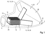
- an ITE hearing aid device 1 is partially shown.
- the housing 2 has a first housing section 2A and an adjoining second housing section 2B.
- the first housing section 2A extends from an end on the eardrum side in the direction of the second housing section, which ends on a side facing away from the eardrum side.
- the first housing section 2A is designed to be at least partially inserted into the auditory canal of a person who is particularly hard of hearing.
- the second housing section 2B adjoins and widens as a whole. As a result, a widening interior space 4 is formed.
- the second housing section 2B has a comparatively large opening at the end. This is typically closed by a so-called faceplate, i.e. a component carrier on which connections, operating elements or even hearing components are often arranged.
- faceplate i.e. a component carrier on which connections, operating elements or even hearing components are often arranged.
- further components some of which are not shown here, such as the battery, signal processing, microphones, etc. are arranged.
- the first housing section 2A has a sound channel 6 at the end of the eardrum, from which sound emerges in the direction of the eardrum.
- a receiver 8 as an electrical component, which extends at least a little way into the sound channel 6 (the receiver 8 is in the Fig. 1 not shown).
- Inside the housing 2 there is an antenna arrangement 7, which has a shielding film 10 and a winding 12 designed as a coil as essential components.
- the winding 12 as well as part of the shielding film 10 surrounds a free space in which the receiver 8 lies, as shown in particular in the illustration of FIG Fig. 2 can be found.
- the winding 12 is only arranged in the area of the receiver 8. This and thus the free space surrounded by the winding 12 extend in a longitudinal direction 14 ( Fig. 2 ), which is oriented away from the eardrum side of the housing 2.
- the shielding film 10 generally has a section 16 which is placed around the earpiece 8 on the circumferential side. This subsection 16 is followed approximately in the longitudinal direction 14 by individual (shielding) tabs 18 in which the shielding film 10 is guided further. In the typical configuration of the earpiece 8 as a cuboid component, one cuboid side is led further through a respective tab 18. The individual tabs 18 are separated from one another at least outside of the subsection 16. The winding 12 is arranged around the shielding film 10 only in the area of the subsection 16.
- the tabs 18 widen, so that an intermediate space 20 formed between them widens - viewed in the longitudinal direction 14.
- the respective tabs 18 enclose a kink angle to the longitudinal direction.
- an articulated joint 22 is formed at the transition between a respective tab 18 to the subsection 16, at which the respective tab 18 is bent.
- the articulation joint 22 is, for example, a film hinge formed by a material tapering of the shielding film 10.
- a respective articulation joint 22 is oriented perpendicular to the longitudinal direction 14 and parallel to a front edge of the receiver 8.
- the shielding film 10 and in particular the tabs 18 have sufficiently good bending flexibility so that they can be easily bent over due to their bending flexibility.
- the individual tabs 18 nestle against an inner wall 24 of the housing 2, especially in the area of the second, expanding housing section 2B.
- the tabs 18 are preferably fastened to the inner wall at least at certain points or also over an area, in particular by gluing.
- the shielding film 10 is multi-layered and has at least two layers, namely a magnetic layer 26, which is formed in particular by one or more ferrite films, and an electrical shielding layer 28, which is in particular formed by a film or layer with good electrical conductivity.
- the electrically conductive material is, in particular, copper.
- the electrical shield layer is oriented in the direction of the receiver 8 and the magnetic layer 26 is arranged between the electrical shield layer 28 and the winding 12.
- the shielding film 10 is formed by the electrical shielding layer 28, in particular copper foil, and the magnetic layer 26 attached thereon, in particular by gluing applied to the shield layer 28.
- the magnetic layer 26 is made up of individual strips 30 extending in the longitudinal direction (cf. in particular in this regard Fig. 4 ) which are individually applied to the electrical shielding layer (in particular copper foil) 28. These individual strips 30 are each foil-like strips, specifically ferrite foil strips.
- the shielding film 10 has a printed circuit board film 32.
- the electrical shielding layer 28 is formed by a conductive layer of the printed circuit board film 32. Specifically, it is, for example, an intermediate layer that is formed between two insulating plastic layers of the printed circuit board film 32.
- the shielding layer 28 can also be applied on one side to an insulating carrier film of the printed circuit board film 32.
- the magnetic layer 26 is in turn applied on the outside.
- this is preferably formed by individual strips 30.
- the magnetic layer 26 is in turn applied to the printed circuit board film 32, for example by gluing. Furthermore, in Fig. 2 to recognize the outside applied winding 10.
- the individual tabs 18 adjoin, of which in the cross-sectional illustration of the Fig. 2 two opposite tabs 18 can be seen.
- further electrical components 34 are preferably arranged directly on the printed circuit board film 32 and are also electrically contacted via the printed circuit board film 32, for example.
- the printed circuit board film 32 has, in addition to the shielding layer 28, conductor tracks and / or further conductive intermediate layers, via which the components 34 are electrically connected to one another.
- the receiver 8 which is square when viewed in cross section, is initially arranged on the inside.
- the electrical shield layer 28 is initially arranged circumferentially. This is wrapped around the circumference, preferably continuously without interruptions, around the receiver 8.
- a separating gap can be formed in a joint or corner area, as shown in FIG Fig. 3 is shown.
- the individual strips 30 of the magnetic layer 26 can be seen, which are therefore each arranged on one of the sides of the cuboid.
- the winding 12 is arranged around the shielding film 10.
- the shielding film 10 is formed by a, for example, rectangular electrical shielding layer 28 which, viewed in the longitudinal direction 12, is slotted over a partial area.
- the individual tabs 18 are formed by the slits introduced.
- the unslotted area forms the subsection 16.
- Strips 30 are applied to this shielding layer 28 - exactly one for each side of the parallelepiped. These extend continuously over the subsection 16 and over the tabs 18.
- the electrical shield layer 28 protrudes beyond the magnetic layer 26 in an end region 36, especially in the direction opposite to the longitudinal direction 14. This is particularly also based on the Fig. 2 to recognize.
- the shield layer 28 projects beyond the magnetic layer 26 in the direction of the eardrum side and on the side facing away from the tabs 18.
- the protrusion is, for example, between 3% and 10% of the length of the section 16 in the longitudinal direction 14.
- the magnetic layer 26 extends to the end of the shielding layer 28.
- the magnetic layer 26 can be set back somewhat. Overall, therefore, the magnetic layer 26 extends at least largely over the entire length of the electrical shield layer 28.
- the tabs 18 protruding beyond the subsection 16 each have a widening electrical shielding layer 28.
- the shield layer 28 widens starting from the beginning of the flap 18 at the section 16 by at least 30%, 50%, 100%, 200% or even more (based on the width at the beginning of the flap 18 at the section 16).
- Each of the typically four tabs 18 is designed in this way. The widening is preferably selected such that when the tabs 18 are widened and nestled against the inner wall 24 of the housing 2, the inner wall 24 is completely or at least largely completely covered in the circumferential direction by the shielding layer 28. As a result, the entire intermediate space 20 is shielded by the electrical shield layer 28.
- a respective strip 30 of the magnetic layer 26 is continued unchanged in the area of the respective tab 18, ie it does not experience any widening.
- the magnetic layer 26 is also designed to widen.
- the antenna arrangement 4 described here can also be transferred to other hearing aid devices and, in general, also to hearing aids specially worn on the head. This also includes headsets, wearables, etc., in particular.
- the electrical component surrounded by the subsection 16 does not necessarily have to be the earpiece 8.
- the antenna arrangement 7 described here is preferably used for data transmission in the MHz range. In addition or alternatively, inductive charging or also as a telecoil is used.
Applications Claiming Priority (1)
| Application Number | Priority Date | Filing Date | Title |
|---|---|---|---|
| DE102019217861.8A DE102019217861B3 (de) | 2019-11-20 | 2019-11-20 | Hörgerät |
Publications (3)
| Publication Number | Publication Date |
|---|---|
| EP3826327A1 true EP3826327A1 (fr) | 2021-05-26 |
| EP3826327C0 EP3826327C0 (fr) | 2023-12-13 |
| EP3826327B1 EP3826327B1 (fr) | 2023-12-13 |
Family
ID=72944143
Family Applications (2)
| Application Number | Title | Priority Date | Filing Date |
|---|---|---|---|
| EP20793331.8A Pending EP4046394A1 (fr) | 2019-11-20 | 2020-10-15 | Procédé pour produire une aide auditive et aide auditive |
| EP20204523.3A Active EP3826327B1 (fr) | 2019-11-20 | 2020-10-29 | Appareil auditif |
Family Applications Before (1)
| Application Number | Title | Priority Date | Filing Date |
|---|---|---|---|
| EP20793331.8A Pending EP4046394A1 (fr) | 2019-11-20 | 2020-10-15 | Procédé pour produire une aide auditive et aide auditive |
Country Status (5)
| Country | Link |
|---|---|
| US (3) | US11343627B2 (fr) |
| EP (2) | EP4046394A1 (fr) |
| CN (2) | CN114868405A (fr) |
| DE (1) | DE102019217861B3 (fr) |
| WO (1) | WO2021099038A1 (fr) |
Families Citing this family (2)
| Publication number | Priority date | Publication date | Assignee | Title |
|---|---|---|---|---|
| WO2020028085A1 (fr) | 2018-07-31 | 2020-02-06 | Earlens Corporation | Évent d'embout d'auriculaire dans un système auditif de contact |
| DE102020213427A1 (de) * | 2020-10-23 | 2022-04-28 | Sivantos Pte. Ltd. | Ladesystem sowie Ladevorrichtung für ein Hörgerät |
Citations (6)
| Publication number | Priority date | Publication date | Assignee | Title |
|---|---|---|---|---|
| US5436803A (en) * | 1993-12-16 | 1995-07-25 | Schlegel Corporation | Emi shielding having flexible conductive envelope |
| US7260234B2 (en) * | 2002-08-12 | 2007-08-21 | Siemens Audiologische Technik Gmbh | Space-saving antenna arrangement for hearing aid device |
| EP2811761A1 (fr) | 2013-06-07 | 2014-12-10 | Siemens Medical Instruments Pte. Ltd. | Dispositif d'antenne pour appareils auditifs |
| US20160241063A1 (en) * | 2013-10-02 | 2016-08-18 | Nitto Denko Corporation | Hearing aid and hearing-aid charging system |
| EP3413587A1 (fr) | 2017-06-09 | 2018-12-12 | Sivantos Pte. Ltd. | Appareil auditif, en particulier appareil de correction auditive derrière l'oreille |
| GB2569536A (en) * | 2017-12-18 | 2019-06-26 | Sonova Ag | Wireless power for a hearing device |
Family Cites Families (10)
| Publication number | Priority date | Publication date | Assignee | Title |
|---|---|---|---|---|
| US20110194717A1 (en) * | 2008-09-26 | 2011-08-11 | Oticon A/S | Hearing aid with exchangeable shell parts and wireless communication |
| DK2375784T3 (da) * | 2010-03-26 | 2014-09-29 | Siemens Medical Instr Pte Ltd | Høreapparat med amorf højttalerafskærmning |
| CN104170407A (zh) * | 2012-03-16 | 2014-11-26 | 锋纳克公司 | 用于听力装置的天线、设置有该天线的耳塞和听力装置 |
| DE102014200524A1 (de) | 2014-01-14 | 2015-07-16 | Siemens Medical Instruments Pte. Ltd. | Antenneneinrichtung für Hörinstrumente |
| JP6464280B2 (ja) | 2015-03-13 | 2019-02-06 | シバントス ピーティーイー リミテッド | 両耳補聴器システム |
| US9866945B2 (en) * | 2016-01-12 | 2018-01-09 | Apple Inc. | Antennas for wireless earbuds |
| DK3427339T3 (da) * | 2016-03-07 | 2020-12-07 | Sivantos Pte Ltd | Antenne |
| US11070928B2 (en) | 2016-09-29 | 2021-07-20 | Sonova Ag | Hearing device and a method for manufacturing thereof |
| CN108322881A (zh) * | 2018-04-26 | 2018-07-24 | 恩平市鼎力音响设备有限公司 | 一种防脱落的弱听人士的发射和接收装置 |
| DE102018214199B3 (de) * | 2018-08-22 | 2020-01-30 | Sivantos Pte. Ltd. | Performante magnetisch induktive Antenne für ein Hörinstrument |
-
2019
- 2019-11-20 DE DE102019217861.8A patent/DE102019217861B3/de active Active
-
2020
- 2020-10-15 EP EP20793331.8A patent/EP4046394A1/fr active Pending
- 2020-10-15 CN CN202080090004.7A patent/CN114868405A/zh active Pending
- 2020-10-15 WO PCT/EP2020/079102 patent/WO2021099038A1/fr unknown
- 2020-10-29 EP EP20204523.3A patent/EP3826327B1/fr active Active
- 2020-11-17 CN CN202011285386.7A patent/CN112825565B/zh active Active
- 2020-11-19 US US16/952,594 patent/US11343627B2/en active Active
-
2022
- 2022-04-25 US US17/728,161 patent/US11627423B2/en active Active
- 2022-05-20 US US17/749,377 patent/US20220279295A1/en active Pending
Patent Citations (6)
| Publication number | Priority date | Publication date | Assignee | Title |
|---|---|---|---|---|
| US5436803A (en) * | 1993-12-16 | 1995-07-25 | Schlegel Corporation | Emi shielding having flexible conductive envelope |
| US7260234B2 (en) * | 2002-08-12 | 2007-08-21 | Siemens Audiologische Technik Gmbh | Space-saving antenna arrangement for hearing aid device |
| EP2811761A1 (fr) | 2013-06-07 | 2014-12-10 | Siemens Medical Instruments Pte. Ltd. | Dispositif d'antenne pour appareils auditifs |
| US20160241063A1 (en) * | 2013-10-02 | 2016-08-18 | Nitto Denko Corporation | Hearing aid and hearing-aid charging system |
| EP3413587A1 (fr) | 2017-06-09 | 2018-12-12 | Sivantos Pte. Ltd. | Appareil auditif, en particulier appareil de correction auditive derrière l'oreille |
| GB2569536A (en) * | 2017-12-18 | 2019-06-26 | Sonova Ag | Wireless power for a hearing device |
Non-Patent Citations (2)
| Title |
|---|
| "EMC for Product Designers", 26 September 2016, NEWNES, ELSEVIER SCIENCE & TECHNOLOGY, ISBN: 978-0-08-101016-7, article TIM WILLIAMS: "15.1.2 LF magnetic fields", pages: 438 - 439, XP055761165 * |
| ANONYMOUS: "101 EMI Shielding Tips and Tricks", ARCHIVED BY WAYBACK MACHINE INTERNET ARCHIVE, 5 November 2017 (2017-11-05), pages 1 - 23, XP055793023, Retrieved from the Internet <URL:https://web.archive.org/web/20171105215145/https://hollandshielding.com/Shielding-tips-and-tricks> [retrieved on 20210407] * |
Also Published As
| Publication number | Publication date |
|---|---|
| CN114868405A (zh) | 2022-08-05 |
| EP3826327C0 (fr) | 2023-12-13 |
| US11343627B2 (en) | 2022-05-24 |
| CN112825565A (zh) | 2021-05-21 |
| CN112825565B (zh) | 2022-07-26 |
| US20220248155A1 (en) | 2022-08-04 |
| WO2021099038A1 (fr) | 2021-05-27 |
| DE102019217861B3 (de) | 2021-05-20 |
| US20210152958A1 (en) | 2021-05-20 |
| US20220279295A1 (en) | 2022-09-01 |
| EP3826327B1 (fr) | 2023-12-13 |
| EP4046394A1 (fr) | 2022-08-24 |
| US11627423B2 (en) | 2023-04-11 |
Similar Documents
| Publication | Publication Date | Title |
|---|---|---|
| EP3427339B1 (fr) | Antenne | |
| EP3413587B1 (fr) | Appareil auditif, en particulier appareil de correction auditive derrière l'oreille | |
| EP2811761B1 (fr) | Dispositif d'antenne pour appareils auditifs | |
| EP3579336B1 (fr) | Antenne ainsi qu'appareil doté d'une telle antenne | |
| EP2782363B1 (fr) | Appareillage auditif binaural et écouteur | |
| EP3826327B1 (fr) | Appareil auditif | |
| EP3840417B1 (fr) | Module d'appareil auditif, appareil auditif et ensemble d'appareil auditif | |
| DE102007042592A1 (de) | Übertragungseinrichtung für eine Hörvorrichtung mit Folienleiterschirmung und eigengeschirmte Spule | |
| DE102007007800B3 (de) | Hörvorrichtung mit Hörerkompensationsspule | |
| EP3836565B1 (fr) | Carte de circuit imprimé d'un appareil auditif | |
| EP3209032A1 (fr) | Module de haut-parleur pour un appareil auditif et appareil auditif | |
| DE102017012195B4 (de) | Hörgerät, insbesondere Hinter-dem-Ohr-Hörhilfegerät | |
| EP3484179A1 (fr) | Appareil de correction auditive | |
| EP3863305A1 (fr) | Appareil auditif | |
| EP2911312B1 (fr) | Antenne dotée de dispositif de protection et procédé de fabrication | |
| WO2018024392A1 (fr) | Aide auditive équipée d'une antenne rf | |
| DE102021201095A1 (de) | Platzsparende Antenne für ein Hörinstrument | |
| EP3863304B1 (fr) | Appareil auditif avec antenne à couplage inductif | |
| DE19602453C1 (de) | Elektrisches Hörhilfegerät | |
| EP3993447A1 (fr) | Système de charge, ainsi que dispositif de charge pour un appareil auditif | |
| EP4104458B1 (fr) | Antenne économisant l'espace magneto inductive pour aide auditive | |
| EP4054208A1 (fr) | Appareil auditif, antenne pour un appareil auditif et procédé de fabrication d'un appareil auditif | |
| DE202020105891U1 (de) | Akustisches Mikrofon mit integriertem magnetischem Wandler | |
| EP1443677A1 (fr) | Appareil électrique | |
| DE102009008618A1 (de) | Hörvorrichtung mit zwei elektrischen Einheiten, die über Drähte mit einander verbunden sind. |
Legal Events
| Date | Code | Title | Description |
|---|---|---|---|
| PUAI | Public reference made under article 153(3) epc to a published international application that has entered the european phase |
Free format text: ORIGINAL CODE: 0009012 |
|
| STAA | Information on the status of an ep patent application or granted ep patent |
Free format text: STATUS: THE APPLICATION HAS BEEN PUBLISHED |
|
| AK | Designated contracting states |
Kind code of ref document: A1 Designated state(s): AL AT BE BG CH CY CZ DE DK EE ES FI FR GB GR HR HU IE IS IT LI LT LU LV MC MK MT NL NO PL PT RO RS SE SI SK SM TR |
|
| STAA | Information on the status of an ep patent application or granted ep patent |
Free format text: STATUS: REQUEST FOR EXAMINATION WAS MADE |
|
| 17P | Request for examination filed |
Effective date: 20211125 |
|
| RBV | Designated contracting states (corrected) |
Designated state(s): AL AT BE BG CH CY CZ DE DK EE ES FI FR GB GR HR HU IE IS IT LI LT LU LV MC MK MT NL NO PL PT RO RS SE SI SK SM TR |
|
| GRAP | Despatch of communication of intention to grant a patent |
Free format text: ORIGINAL CODE: EPIDOSNIGR1 |
|
| STAA | Information on the status of an ep patent application or granted ep patent |
Free format text: STATUS: GRANT OF PATENT IS INTENDED |
|
| RIC1 | Information provided on ipc code assigned before grant |
Ipc: H01F 27/40 20060101ALN20230622BHEP Ipc: H01F 27/32 20060101ALN20230622BHEP Ipc: H01F 38/14 20060101ALN20230622BHEP Ipc: H04R 25/00 20060101AFI20230622BHEP |
|
| INTG | Intention to grant announced |
Effective date: 20230706 |
|
| RIC1 | Information provided on ipc code assigned before grant |
Ipc: H01F 27/40 20060101ALN20230623BHEP Ipc: H01F 27/32 20060101ALN20230623BHEP Ipc: H01F 38/14 20060101ALN20230623BHEP Ipc: H04R 25/00 20060101AFI20230623BHEP |
|
| GRAS | Grant fee paid |
Free format text: ORIGINAL CODE: EPIDOSNIGR3 |
|
| GRAA | (expected) grant |
Free format text: ORIGINAL CODE: 0009210 |
|
| STAA | Information on the status of an ep patent application or granted ep patent |
Free format text: STATUS: THE PATENT HAS BEEN GRANTED |
|
| AK | Designated contracting states |
Kind code of ref document: B1 Designated state(s): AL AT BE BG CH CY CZ DE DK EE ES FI FR GB GR HR HU IE IS IT LI LT LU LV MC MK MT NL NO PL PT RO RS SE SI SK SM TR |
|
| REG | Reference to a national code |
Ref country code: GB Ref legal event code: FG4D Free format text: NOT ENGLISH |
|
| REG | Reference to a national code |
Ref country code: CH Ref legal event code: EP |
|
| REG | Reference to a national code |
Ref country code: DE Ref legal event code: R096 Ref document number: 502020006369 Country of ref document: DE |
|
| REG | Reference to a national code |
Ref country code: IE Ref legal event code: FG4D Free format text: LANGUAGE OF EP DOCUMENT: GERMAN |
|
| U01 | Request for unitary effect filed |
Effective date: 20231218 |
|
| U07 | Unitary effect registered |
Designated state(s): AT BE BG DE DK EE FI FR IT LT LU LV MT NL PT SE SI Effective date: 20231222 |
|
| PG25 | Lapsed in a contracting state [announced via postgrant information from national office to epo] |
Ref country code: GR Free format text: LAPSE BECAUSE OF FAILURE TO SUBMIT A TRANSLATION OF THE DESCRIPTION OR TO PAY THE FEE WITHIN THE PRESCRIBED TIME-LIMIT Effective date: 20240314 |
|
| PG25 | Lapsed in a contracting state [announced via postgrant information from national office to epo] |
Ref country code: ES Free format text: LAPSE BECAUSE OF FAILURE TO SUBMIT A TRANSLATION OF THE DESCRIPTION OR TO PAY THE FEE WITHIN THE PRESCRIBED TIME-LIMIT Effective date: 20231213 |
|
| PG25 | Lapsed in a contracting state [announced via postgrant information from national office to epo] |
Ref country code: GR Free format text: LAPSE BECAUSE OF FAILURE TO SUBMIT A TRANSLATION OF THE DESCRIPTION OR TO PAY THE FEE WITHIN THE PRESCRIBED TIME-LIMIT Effective date: 20240314 Ref country code: ES Free format text: LAPSE BECAUSE OF FAILURE TO SUBMIT A TRANSLATION OF THE DESCRIPTION OR TO PAY THE FEE WITHIN THE PRESCRIBED TIME-LIMIT Effective date: 20231213 |