EP3826327A1 - Hearing aid - Google Patents
Hearing aid Download PDFInfo
- Publication number
- EP3826327A1 EP3826327A1 EP20204523.3A EP20204523A EP3826327A1 EP 3826327 A1 EP3826327 A1 EP 3826327A1 EP 20204523 A EP20204523 A EP 20204523A EP 3826327 A1 EP3826327 A1 EP 3826327A1
- Authority
- EP
- European Patent Office
- Prior art keywords
- hearing aid
- layer
- electrical
- magnetic layer
- tabs
- Prior art date
- Legal status (The legal status is an assumption and is not a legal conclusion. Google has not performed a legal analysis and makes no representation as to the accuracy of the status listed.)
- Granted
Links
- 230000005291 magnetic effect Effects 0.000 claims abstract description 77
- 238000004804 winding Methods 0.000 claims abstract description 22
- 229910000859 α-Fe Inorganic materials 0.000 claims description 7
- 230000005855 radiation Effects 0.000 claims description 6
- 238000012545 processing Methods 0.000 claims description 5
- 238000013461 design Methods 0.000 abstract description 10
- 230000035945 sensitivity Effects 0.000 abstract description 9
- 239000000463 material Substances 0.000 description 15
- 239000011888 foil Substances 0.000 description 11
- 210000003454 tympanic membrane Anatomy 0.000 description 9
- RYGMFSIKBFXOCR-UHFFFAOYSA-N Copper Chemical compound [Cu] RYGMFSIKBFXOCR-UHFFFAOYSA-N 0.000 description 7
- 238000004026 adhesive bonding Methods 0.000 description 7
- 230000035699 permeability Effects 0.000 description 7
- 238000011161 development Methods 0.000 description 6
- 230000001939 inductive effect Effects 0.000 description 6
- 230000006978 adaptation Effects 0.000 description 4
- 238000005452 bending Methods 0.000 description 4
- 230000008901 benefit Effects 0.000 description 4
- 230000005540 biological transmission Effects 0.000 description 4
- 239000004020 conductor Substances 0.000 description 4
- 239000010949 copper Substances 0.000 description 4
- 229910052802 copper Inorganic materials 0.000 description 4
- 230000000694 effects Effects 0.000 description 4
- 239000000696 magnetic material Substances 0.000 description 4
- 238000004891 communication Methods 0.000 description 3
- 239000011889 copper foil Substances 0.000 description 3
- 210000003128 head Anatomy 0.000 description 3
- 208000032041 Hearing impaired Diseases 0.000 description 2
- 238000005266 casting Methods 0.000 description 2
- 210000000613 ear canal Anatomy 0.000 description 2
- 230000005672 electromagnetic field Effects 0.000 description 2
- 238000010438 heat treatment Methods 0.000 description 2
- 238000000034 method Methods 0.000 description 2
- 230000008569 process Effects 0.000 description 2
- 230000007704 transition Effects 0.000 description 2
- 206010048865 Hypoacusis Diseases 0.000 description 1
- 230000003321 amplification Effects 0.000 description 1
- 210000000988 bone and bone Anatomy 0.000 description 1
- 238000010276 construction Methods 0.000 description 1
- 230000006735 deficit Effects 0.000 description 1
- 238000004146 energy storage Methods 0.000 description 1
- 230000005293 ferrimagnetic effect Effects 0.000 description 1
- 230000005294 ferromagnetic effect Effects 0.000 description 1
- 230000006870 function Effects 0.000 description 1
- 208000016354 hearing loss disease Diseases 0.000 description 1
- 230000006872 improvement Effects 0.000 description 1
- 230000006698 induction Effects 0.000 description 1
- 238000002347 injection Methods 0.000 description 1
- 239000007924 injection Substances 0.000 description 1
- 230000002452 interceptive effect Effects 0.000 description 1
- 239000006249 magnetic particle Substances 0.000 description 1
- 238000004519 manufacturing process Methods 0.000 description 1
- 239000011159 matrix material Substances 0.000 description 1
- 238000003199 nucleic acid amplification method Methods 0.000 description 1
- 230000005298 paramagnetic effect Effects 0.000 description 1
- 230000008447 perception Effects 0.000 description 1
- 230000005236 sound signal Effects 0.000 description 1
- 238000002560 therapeutic procedure Methods 0.000 description 1
Images


Classifications
-
- H—ELECTRICITY
- H04—ELECTRIC COMMUNICATION TECHNIQUE
- H04R—LOUDSPEAKERS, MICROPHONES, GRAMOPHONE PICK-UPS OR LIKE ACOUSTIC ELECTROMECHANICAL TRANSDUCERS; DEAF-AID SETS; PUBLIC ADDRESS SYSTEMS
- H04R25/00—Deaf-aid sets, i.e. electro-acoustic or electro-mechanical hearing aids; Electric tinnitus maskers providing an auditory perception
- H04R25/55—Deaf-aid sets, i.e. electro-acoustic or electro-mechanical hearing aids; Electric tinnitus maskers providing an auditory perception using an external connection, either wireless or wired
- H04R25/554—Deaf-aid sets, i.e. electro-acoustic or electro-mechanical hearing aids; Electric tinnitus maskers providing an auditory perception using an external connection, either wireless or wired using a wireless connection, e.g. between microphone and amplifier or using Tcoils
-
- H—ELECTRICITY
- H04—ELECTRIC COMMUNICATION TECHNIQUE
- H04R—LOUDSPEAKERS, MICROPHONES, GRAMOPHONE PICK-UPS OR LIKE ACOUSTIC ELECTROMECHANICAL TRANSDUCERS; DEAF-AID SETS; PUBLIC ADDRESS SYSTEMS
- H04R25/00—Deaf-aid sets, i.e. electro-acoustic or electro-mechanical hearing aids; Electric tinnitus maskers providing an auditory perception
- H04R25/60—Mounting or interconnection of hearing aid parts, e.g. inside tips, housings or to ossicles
- H04R25/609—Mounting or interconnection of hearing aid parts, e.g. inside tips, housings or to ossicles of circuitry
-
- H—ELECTRICITY
- H04—ELECTRIC COMMUNICATION TECHNIQUE
- H04R—LOUDSPEAKERS, MICROPHONES, GRAMOPHONE PICK-UPS OR LIKE ACOUSTIC ELECTROMECHANICAL TRANSDUCERS; DEAF-AID SETS; PUBLIC ADDRESS SYSTEMS
- H04R25/00—Deaf-aid sets, i.e. electro-acoustic or electro-mechanical hearing aids; Electric tinnitus maskers providing an auditory perception
- H04R25/60—Mounting or interconnection of hearing aid parts, e.g. inside tips, housings or to ossicles
- H04R25/602—Mounting or interconnection of hearing aid parts, e.g. inside tips, housings or to ossicles of batteries
-
- H—ELECTRICITY
- H04—ELECTRIC COMMUNICATION TECHNIQUE
- H04R—LOUDSPEAKERS, MICROPHONES, GRAMOPHONE PICK-UPS OR LIKE ACOUSTIC ELECTROMECHANICAL TRANSDUCERS; DEAF-AID SETS; PUBLIC ADDRESS SYSTEMS
- H04R25/00—Deaf-aid sets, i.e. electro-acoustic or electro-mechanical hearing aids; Electric tinnitus maskers providing an auditory perception
- H04R25/60—Mounting or interconnection of hearing aid parts, e.g. inside tips, housings or to ossicles
- H04R25/604—Mounting or interconnection of hearing aid parts, e.g. inside tips, housings or to ossicles of acoustic or vibrational transducers
-
- H—ELECTRICITY
- H04—ELECTRIC COMMUNICATION TECHNIQUE
- H04R—LOUDSPEAKERS, MICROPHONES, GRAMOPHONE PICK-UPS OR LIKE ACOUSTIC ELECTROMECHANICAL TRANSDUCERS; DEAF-AID SETS; PUBLIC ADDRESS SYSTEMS
- H04R25/00—Deaf-aid sets, i.e. electro-acoustic or electro-mechanical hearing aids; Electric tinnitus maskers providing an auditory perception
- H04R25/65—Housing parts, e.g. shells, tips or moulds, or their manufacture
- H04R25/658—Manufacture of housing parts
-
- H—ELECTRICITY
- H05—ELECTRIC TECHNIQUES NOT OTHERWISE PROVIDED FOR
- H05K—PRINTED CIRCUITS; CASINGS OR CONSTRUCTIONAL DETAILS OF ELECTRIC APPARATUS; MANUFACTURE OF ASSEMBLAGES OF ELECTRICAL COMPONENTS
- H05K9/00—Screening of apparatus or components against electric or magnetic fields
- H05K9/0073—Shielding materials
- H05K9/0081—Electromagnetic shielding materials, e.g. EMI, RFI shielding
- H05K9/0084—Electromagnetic shielding materials, e.g. EMI, RFI shielding comprising a single continuous metallic layer on an electrically insulating supporting structure, e.g. metal foil, film, plating coating, electro-deposition, vapour-deposition
-
- H—ELECTRICITY
- H01—ELECTRIC ELEMENTS
- H01F—MAGNETS; INDUCTANCES; TRANSFORMERS; SELECTION OF MATERIALS FOR THEIR MAGNETIC PROPERTIES
- H01F27/00—Details of transformers or inductances, in general
- H01F27/28—Coils; Windings; Conductive connections
- H01F27/32—Insulating of coils, windings, or parts thereof
- H01F27/324—Insulation between coil and core, between different winding sections, around the coil; Other insulation structures
- H01F27/325—Coil bobbins
-
- H—ELECTRICITY
- H01—ELECTRIC ELEMENTS
- H01F—MAGNETS; INDUCTANCES; TRANSFORMERS; SELECTION OF MATERIALS FOR THEIR MAGNETIC PROPERTIES
- H01F27/00—Details of transformers or inductances, in general
- H01F27/34—Special means for preventing or reducing unwanted electric or magnetic effects, e.g. no-load losses, reactive currents, harmonics, oscillations, leakage fields
- H01F27/36—Electric or magnetic shields or screens
- H01F27/366—Electric or magnetic shields or screens made of ferromagnetic material
-
- H—ELECTRICITY
- H01—ELECTRIC ELEMENTS
- H01F—MAGNETS; INDUCTANCES; TRANSFORMERS; SELECTION OF MATERIALS FOR THEIR MAGNETIC PROPERTIES
- H01F27/00—Details of transformers or inductances, in general
- H01F27/40—Structural association with built-in electric component, e.g. fuse
-
- H—ELECTRICITY
- H01—ELECTRIC ELEMENTS
- H01F—MAGNETS; INDUCTANCES; TRANSFORMERS; SELECTION OF MATERIALS FOR THEIR MAGNETIC PROPERTIES
- H01F38/00—Adaptations of transformers or inductances for specific applications or functions
- H01F38/14—Inductive couplings
-
- H—ELECTRICITY
- H04—ELECTRIC COMMUNICATION TECHNIQUE
- H04R—LOUDSPEAKERS, MICROPHONES, GRAMOPHONE PICK-UPS OR LIKE ACOUSTIC ELECTROMECHANICAL TRANSDUCERS; DEAF-AID SETS; PUBLIC ADDRESS SYSTEMS
- H04R2225/00—Details of deaf aids covered by H04R25/00, not provided for in any of its subgroups
- H04R2225/025—In the ear hearing aids [ITE] hearing aids
-
- H—ELECTRICITY
- H04—ELECTRIC COMMUNICATION TECHNIQUE
- H04R—LOUDSPEAKERS, MICROPHONES, GRAMOPHONE PICK-UPS OR LIKE ACOUSTIC ELECTROMECHANICAL TRANSDUCERS; DEAF-AID SETS; PUBLIC ADDRESS SYSTEMS
- H04R2225/00—Details of deaf aids covered by H04R25/00, not provided for in any of its subgroups
- H04R2225/49—Reducing the effects of electromagnetic noise on the functioning of hearing aids, by, e.g. shielding, signal processing adaptation, selective (de)activation of electronic parts in hearing aid
-
- H—ELECTRICITY
- H04—ELECTRIC COMMUNICATION TECHNIQUE
- H04R—LOUDSPEAKERS, MICROPHONES, GRAMOPHONE PICK-UPS OR LIKE ACOUSTIC ELECTROMECHANICAL TRANSDUCERS; DEAF-AID SETS; PUBLIC ADDRESS SYSTEMS
- H04R2225/00—Details of deaf aids covered by H04R25/00, not provided for in any of its subgroups
- H04R2225/51—Aspects of antennas or their circuitry in or for hearing aids
-
- H—ELECTRICITY
- H04—ELECTRIC COMMUNICATION TECHNIQUE
- H04R—LOUDSPEAKERS, MICROPHONES, GRAMOPHONE PICK-UPS OR LIKE ACOUSTIC ELECTROMECHANICAL TRANSDUCERS; DEAF-AID SETS; PUBLIC ADDRESS SYSTEMS
- H04R2225/00—Details of deaf aids covered by H04R25/00, not provided for in any of its subgroups
- H04R2225/57—Aspects of electrical interconnection between hearing aid parts
Definitions
- the invention relates to a hearing aid, in particular an ITE hearing aid with the features of the preamble of claim 1.
- Hearing aid is generally understood to mean a device which is designed to process and present sound or a sound signal to a person.
- the present invention particularly relates to a hearing aid device.
- This is understood to mean a hearing aid which is used to supply a hearing-impaired person with acoustic ambient signals.
- the acoustic ambient signals are processed and in particular amplified for compensation or therapy of a respective hearing impairment.
- Such a hearing aid device basically consists of one or more input transducers, a signal processing device, an amplification device and an output transducer.
- the input transducer is usually a sound receiver, for example a microphone and / or an electromagnetic receiver, for example an induction coil.
- the output transducer is usually implemented as an electroacoustic transducer, for example a loudspeaker, or as an electromechanical transducer, for example a bone conduction receiver. It is also known as a listener or receiver.
- the output transducer generates output signals that are directed to the hearing of the patient (hearing impaired person) and are intended to generate a hearing perception in the patient.
- the amplifier is usually integrated into the signal processing device.
- the hearing aid is powered by a battery integrated in the housing of the hearing aid. (Hearing aid) components are usually arranged or connected to a printed circuit board as a circuit carrier.
- hearing aids in particular hearing aids.
- ITE hearing aids In-the-Ear
- BTE Behind the Ear
- RiC hearing aids Receiver in Canal
- CiC hearing aids Completely in Canal
- the latter are similar to ITE hearing aids, but are worn entirely in the ear canal.
- the housing which contains all functional components including the microphone and receiver, is worn at least partially in the ear canal.
- ITE or CiC hearing aids in particular therefore have a very small design.
- Hearing aids especially hearing aids, often have an antenna arrangement which is used, for example, for the wireless transmission of data signals or acoustic signals.
- the antenna arrangements can be provided for different purposes.
- the antenna arrangement is used for wireless communication with another device, for example with another hearing aid device in the case of binaural supply.
- such an antenna arrangement can also be designed for wireless communication with another external device, for example a playback device for music and speech.
- the antenna arrangement can also be used for wireless, in particular inductive, charging of a battery of the hearing aid device. Because of the limited space, in the case of an antenna arrangement, shielding between the antenna arrangement and further electrical components is often required and desired in order to avoid undesired mutual interference.
- an ITE hearing aid device in which a shielding shield is arranged between a receiver and an antenna arrangement which has a coil, which shield is formed in one piece with a coil core.
- a further hearing aid device in which a winding of an antenna arrangement is arranged on an energy storage device (battery) with a film shield in between.
- the components of the hearing aid must be arranged as compactly as possible.
- the mutual influencing of the components due to electromagnetic influences can be problematic here.
- an electromagnetic output transducer (earpiece) generates strong radiation.
- the aim is generally the highest possible sensitivity of the antenna arrangement with at the same time the least possible mutual influencing.
- the invention is based on the object of enabling a hearing aid with a compact antenna arrangement with high sensitivity.
- the object is achieved by a hearing aid with the features of claim 1.
- the hearing aid generally has a housing. This typically has an interior space that changes in one direction. In the case of an ITE housing, the interior space typically expands from one side of the eardrum of the housing to a side facing away.
- the "eardrum side” is understood to mean that side of the housing with which the housing is inserted into the auditory canal so that this side faces the eardrum of a person.
- the hearing aid has at least one electrical component which is arranged in the housing and extends in a longitudinal direction.
- This is generally a hearing aid component, which therefore has hearing aid functionality. It is preferably the listener.
- an antenna arrangement is integrated in the housing, which has a winding which is arranged on the electrical component.
- a magnetic layer made of a magnetic, ie permeable material is also arranged between the component and the winding. The winding is in particular wound around the electrical component in the manner of a coil with the shielding film interposed.
- the magnetic layer has a section extending along the electrical component. In a preferred embodiment, the subsection is arranged circumferentially around the electrical component.
- the magnetic layer has at least one, and preferably several, on this subsection and thus also on tabs adjoining the electrical component in the longitudinal direction.
- the at least one tab and preferably the plurality of tabs therefore protrude beyond the electrical component.
- the at least one protruding tab delimits an intermediate space which is formed at least by a partial space of the interior of the housing. The space is limited, for example, on one side by the at least one tab and on the other side by an (opposite) inner wall of the housing. If there are several tabs, these preferably enclose the space between them.
- the magnetic layer is functionally designed in the manner of a coil core, as a result of which the overall sensitivity of the antenna arrangement is positively influenced.
- this function of the coil core is initially reinforced.
- magnetic field lines are guided into and through this magnetic tab, with the result that the space is less loaded by magnetic fields than it would be without the at least one tab.
- the intermediate space in particular the intermediate space formed between two tabs, preferably widens in the longitudinal direction.
- the device typically has a first housing section that is adapted to the auditory canal and has a small cross-sectional area, which is followed by a second, widening housing section in which several further hearing aid components are arranged.
- the electrical component surrounded by the shielding film is arranged in the first housing section with the small cross section.
- the widening tabs therefore, in particular, efficiently shield the widening interior space in the second housing section.
- the tab (s) is / are preferably attached to this inner wall, for example by gluing. Depending on the design of the tabs and the flexibility of the tabs, they preferably nestle flat against the contour of the inner wall.
- the at least one tab or several / all tabs extend / extend only partially, i.e. initially continue to run parallel in a partial area and only extend outwardly in an expanding partial area in the direction of the inner wall of the housing.
- an (outer) further space is formed, i.e. a space which is separated by the bracket from the intermediate space.
- this outer space there are preferably further hearing aid components, in particular those with low interference potential such as microphone, switches, programming contacts, etc. are arranged.
- one tab is preferably bent inward. Further tabs are preferably bent outwards and widening.
- the at least one, preferably all, tabs preferably have a length in the longitudinal direction which corresponds to at least 20%, preferably at least 50% and in particular at least 100% of the length of the subsection.
- the length of the tabs is chosen such that - viewed in the longitudinal direction - they cover at least a large part, e.g. at least 75% or at least 90% of the length of the second housing part, so that at least a large part of the inner wall of the housing, in particular of the second housing part, is covered by the Tabs (at least viewed in the longitudinal direction) is covered.
- the tabs themselves preferably adjoin the section in a flexible manner.
- the straps are preferably designed to be flexible overall, so that the desired adaptation to the inner wall is made possible.
- a hinge in the manner of an articulated joint is formed in an expedient embodiment between the subsection and a respective tab, on which the tab is bent relative to the subsection.
- the respective tab can basically be oriented in different angular orientations with respect to the longitudinal direction via this articulated joint.
- the articulation itself is designed, for example, in the manner of a film hinge, for example by introducing a material taper in the area of the articulation.
- the magnetic layer has at least one magnetic film, that is to say a film made of a permeable material.
- the film is a ferrite film.
- the magnetic layer can also have several, for example, strip-shaped foils.
- the magnetic layer consists of the at least one magnetic film.
- the permeability number of the magnetic layer depends, among other things, on the frequency (resonance frequency) to which the antenna arrangement for sending / receiving (data) signals is tuned.
- the antenna arrangement is specifically designed for data transmission at frequencies in the megahertz range, specifically in the range between 1 to 20 MHz, in particular in the range of 3 MHz.
- the antenna arrangement can also be designed for transmitting / receiving in the two- or three-digit megahertz range (for example up to 300 MHz).
- the antenna arrangement is tuned to a resonance frequency in the gigahertz range.
- the antenna arrangement is used for other purposes, for example for inductive charging, typically at frequencies in the kHz range or also as telecoil antennas for frequencies down into the heart range.
- the magnetic layer preferably has a permeability number in the range between 40 and 700, preferably in the range between 100 and 300, particularly in the case of an antenna arrangement that is tailored to the megahertz range, especially the range between 1 and 20 MHz. With increasing frequencies for which the antenna arrangement is designed, smaller permeability numbers are selected for the magnetic film.
- the permeability number is at least> 1, so that the magnetically permeable material used is at least paramagnetic.
- the permeability number is preferably much greater than 1 (at least 5, preferably at least 10) so that the permeable material is generally ferromagnetic or ferrimagnetic.
- an electrical shield layer is arranged in addition to the magnetic layer. This is (only) arranged in the area of the electrical component or (only) in the area of the protruding tab. However, like the magnetic layer, it preferably extends over the electrical component and forms protruding tabs.
- the intermediate area is effectively shielded via the shield layer, so that disruptive effects are reduced.
- the electrical shielding layer is designed as a shielding film at least in partial areas, especially in the area of the tabs.
- the shielding layer is preferably formed by one or, if necessary, also by several shielding foils.
- the magnetic layer and the electrical shielding layer form a common shielding film.
- This is therefore a multi-layer, in particular two-layer film with the electrical shield layer, in particular made of copper and the magnetic layer.
- Electrode is generally understood to mean a highly conductive layer, the electrical conductivity of which is in particular significantly greater (e.g. by at least a factor of 5) than that of the magnetic layer.
- the permeability of the magnetic layer is preferably greater, in particular significantly greater (at least a factor of 5), than the permeability of the electrical shielding layer.
- This film structure achieves at least good shielding and, on the other hand, high sensitivity of the antenna arrangement.
- this structure of the shielding film ensures that only slight eddy currents are produced in the shielding film and thus only very little heating takes place.
- the magnetic field lines run within the magnetic layer.
- the space - viewed from the outer fields - is virtually field-free (H-field, E-field) and is particularly suitable for the arrangement of components. Conversely, any components arranged in the space are shielded from the outside and therefore have little or no effect on the performance of the antenna device.
- a particular advantage of the shielding of the space can be seen in an embodiment of the antenna device for inductive charging.
- inductive charging eddy currents are often induced in a housing of a battery, which among other things leads to undesired heating of the battery. Due to a preferred arrangement of the battery in the intermediate space, it is therefore arranged, as it were, in the field-free space, so that no eddy currents are induced.
- the at least one tab is / are in particular formed by the multilayer shielding film or at least have it.
- the electrical shield layer is preferably oriented in the direction of the electrical component and the magnetic layer in the direction of the winding.
- the magnetic layer is therefore - relative to the electrical shield layer - arranged further out.
- the electrical shield layer is thinner than the magnetic layer.
- the magnetic layer preferably has a thickness in the range of at least 25 ⁇ m, preferably of at least 50 ⁇ m or of at least 100 ⁇ m.
- the maximum thickness is, for example, 500 ⁇ m and preferably a maximum of 200 or a maximum of 300 ⁇ m.
- the thickness of the magnetic layer, especially the thickness of the ferrite foil is in the range between 200 and 300 ⁇ m.
- the thickness of the electrical shielding layer is typically in the range between 5 ⁇ m and 50 ⁇ m and preferably typically in the range between 15 to 35 ⁇ m.
- thicker foils e.g. used with a thickness in the range between 40 ⁇ m to 80 ⁇ m.
- the electrical shielding layer preferably at the end of the shielding film opposite the tabs, protrudes in the longitudinal direction beyond the magnetic layer.
- improved shielding is achieved in the end area of the shielding film, so that the spatial area, in particular within the subsection in which the electrical component is arranged, is as unaffected as possible by the electromagnetic field of the antenna arrangement even in the end area of the subsection. In this way, any interference fields that penetrate into the spatial area surrounded by the subsection are kept low.
- the magnetic layer and the electrical shielding layer are congruent, i.e. they lie on top of one another over their entire surface. This allows simple production, e.g. by creating the desired shape and geometry of the shielding film by means of a stamping process.
- the total length of the subsection typically corresponds to the length of the electrical component. This is often in the range, for example, between 3 and 7 mm, in particular around 5 mm.
- the magnetic layer is, for example, set back in the longitudinal direction by a range of 5% to 20% of the length of the subsection with respect to the electrical shielding layer.
- the tabs preferably have a width that is constant over their length.
- the electrical shield layer and / or the magnetic shield layer widens.
- the electrical shielding layer preferably widens compared to the magnetic layer.
- only the electrical shield layer widens in the area of a respective tab, starting from the subsection.
- the respective magnetic layer is continued in the area of a respective tab, preferably in the form of a strip with a preferably constant width, whereas the electrical shielding layer is enlarged.
- the widening electrical shield layer achieves improved shielding of the widening interspace.
- the shield layer is closed on the circumferential side in the area of the tabs, in particular continuously closed, i.e. there are no gaps or free spaces between (in the circumferential direction) adjacent areas of the tabs.
- the shield layer is preferably closed at least to a large extent on the circumferential side. This is understood to mean that the free spaces in the circumferential direction in which no shield layer is arranged are less than 20% or less than 10% of the circumference. Due to the high flexibility of the electrical shield layer, it is easily possible to adapt the shield layer to the inner wall. At the same time, it is sufficient for the sensitivity of the antenna arrangement if the magnetic layer is only continued in the form of a strip, for example, in the tabs.
- the magnetic layer is formed by individual strips which are at least partially and preferably completely separate from one another and which extend in the longitudinal direction. These therefore extend in particular over the subsection and then merge into a respective tab adjoining the subsection.
- the shield layer can also be formed by individual strips. For example, several strips of shielding film are provided, each of which is fastened, in particular glued, to a side surface of the component.
- the magnetic layer is generally applied to the shielding layer, specifically to the shielding film, in particular by gluing.
- the individual strips are preferably each formed by a foil.
- Both the electrical shield layer and the magnetic layer are formed in preferred variants by a film section and a further section, e.g. a fixed section with high inherent rigidity.
- the magnetic shielding layer is formed in the area of the component, that is to say in the partial section, by a suitable choice of material for the housing of the component.
- the housing therefore consists of a magnetic material or is surrounded by a housing jacket made of the magnetic material.
- This material is, for example, a magnetic (injection) cast material, specifically an injection-molded ferrite.
- This casting material consists, for example, of the magnetic material or it is a plastic casting material with magnetic particles embedded in a plastic matrix.
- the tabs made of the magnetic material or also the multilayer shielding film adjoin this housing and are, for example, attached to it, in particular by gluing.
- the electrical shield layer is formed in the area of the component, that is to say in the partial section, by a suitable choice of material for the housing of the component.
- the housing therefore consists of a material with high electrical conductivity or at least has a corresponding screen wall area.
- the at least one tab is in turn attached to this housing.
- further hearing aid components are arranged in the space. These benefit from the shielding, so that the antenna arrangement and these hearing aid components are as unaffected as possible.
- further components are arranged in the shielded intermediate space. These are specifically, for example, one or more of the components battery, integrated circuits (for example a high-frequency circuit, charging circuit), components of a signal processing device, such as amplifiers, filters, etc.
- a decisive advantage of the shielding of the space by the tabs can also be seen in the fact that comparable electromagnetic conditions are created for the arrangement of these additional hearing components for different hearing aids, so that the mutual influences across different hearing aids are at least largely identical.
- the housings are often designed as so-called customized shells, that is, individually adapted housing shells. This typically changes the space available and the arrangement of the individual components can differ from hearing aid to hearing aid.
- a printed circuit board film which has the shielding layer and / or the magnetic layer.
- the circuit board film has the shielding film.
- the term printed circuit board film is generally understood to mean a film-like carrier which consists of a non-conductive plastic material and on which conductor tracks are preferably attached.
- the electrical shield layer is designed as a plane or layer of this printed circuit board film.
- the printed circuit board film has a type of ground plane formed conductive layer, in particular a copper layer.
- the magnetic layer is applied to the printed circuit board film, in particular by gluing.
- one of the further electrical components is arranged on the printed circuit board film, in particular also electrically contacted, for example via the conductor tracks integrated into the printed circuit board film.
- the further electrical component is preferably oriented in the direction of the intermediate space.
- These components are, in particular, interfering components. Due to their arrangement on the foil, the conditions, such as a signal-to-noise ratio, remain the same regardless of the special design of the housing. This is of particular importance in the case of housings that are individually adapted to the user, since in these the geometry of hearing aid to hearing aid and thus also the arrangement and position of the components can differ.
- the electrical component which is surrounded by the subsection of the shielding film is in particular a receiver / loudspeaker, that is to say an electromagnetic transducer. During operation, this generates a very strong electromagnetic field which is reliably shielded from the antenna arrangement by the shielding film.
- the tabs are designed as reflective surfaces for HF radiation.
- This is understood to mean radiation in the gigahertz range, in particular in the single-digit gigahertz range, for example in the 2.4 GHz range.
- wireless communication or data transmission takes place in such a high-frequency range. It is desirable here that the radiation is not emitted in the direction of the head as far as possible, since the HF radiation is strongly absorbed there.
- the design as an HF reflection surface, which is created in particular by the electrical shield layer, ensures that an HF wave is either radiated in a directional manner or that it is prevented from entering the head area runs into it.
- This HF reflective surface formed by the tabs rests in particular on the inner wall of the housing and preferably over the entire surface.
- the electrical component is typically a component that is cuboid, that is, has a quadrangular cross-section (possibly with rounded corner edges).
- the strip-like configuration of the magnetic layer also ensures that the shielding film is free of the magnetic layer in areas of corner edges (which extend in the longitudinal direction). Since this is thicker, typically significantly thicker, than the electrical shielding layer, the overall thickness of the shielding film is significantly reduced, at least in the corner areas. This results in better adaptation to the housing in the area of the electrical component.
- This is typically arranged in the first housing section, which is inserted into the auditory canal when worn, so that the housing here typically has a rounded cross-sectional contour that is adapted to the auditory canal.
- the interior space in the area of the first housing section is typically completely filled by the electrical component (with the antenna arrangement arranged around it).
- the first housing section typically forms a channel that is adapted to the electrical component and into which the latter is inserted.
- a strip of the shielding film is applied to each side surface of the electrical component, so that the edges of the component are each free of the shielding film.
- the subsection is arranged around the cuboid body of the electrical component around it in the longitudinal direction.
- the opposite end faces are preferably left free, so only the outer surface of the electrical component is covered.
- the winding is then wound around the partial section of the shielding film in the manner of a coil. The winding is only present in the partial section.
- the electrical component does not necessarily have to be completely covered on the circumferential side by the subsection of the shielding film.
- a separating gap or separating slit on opposite abutting edges can exist without significant impairment of functionality.
- the electrical component is preferably surrounded by the subsection over the entire area and over the entire circumference.
- the coil is preferably designed in the manner of an air-core coil, i.e. the individual windings surround an (air) free space.
- a coil is pushed onto the electrical component provided with the shielding film during assembly.
- the coil generally the winding, is electrically contacted in a suitable manner and is connected to a transmitting and / or receiving device.
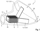
- an ITE hearing aid device 1 is partially shown.
- the housing 2 has a first housing section 2A and an adjoining second housing section 2B.
- the first housing section 2A extends from an end on the eardrum side in the direction of the second housing section, which ends on a side facing away from the eardrum side.
- the first housing section 2A is designed to be at least partially inserted into the auditory canal of a person who is particularly hard of hearing.
- the second housing section 2B adjoins and widens as a whole. As a result, a widening interior space 4 is formed.
- the second housing section 2B has a comparatively large opening at the end. This is typically closed by a so-called faceplate, i.e. a component carrier on which connections, operating elements or even hearing components are often arranged.
- faceplate i.e. a component carrier on which connections, operating elements or even hearing components are often arranged.
- further components some of which are not shown here, such as the battery, signal processing, microphones, etc. are arranged.
- the first housing section 2A has a sound channel 6 at the end of the eardrum, from which sound emerges in the direction of the eardrum.
- a receiver 8 as an electrical component, which extends at least a little way into the sound channel 6 (the receiver 8 is in the Fig. 1 not shown).
- Inside the housing 2 there is an antenna arrangement 7, which has a shielding film 10 and a winding 12 designed as a coil as essential components.
- the winding 12 as well as part of the shielding film 10 surrounds a free space in which the receiver 8 lies, as shown in particular in the illustration of FIG Fig. 2 can be found.
- the winding 12 is only arranged in the area of the receiver 8. This and thus the free space surrounded by the winding 12 extend in a longitudinal direction 14 ( Fig. 2 ), which is oriented away from the eardrum side of the housing 2.
- the shielding film 10 generally has a section 16 which is placed around the earpiece 8 on the circumferential side. This subsection 16 is followed approximately in the longitudinal direction 14 by individual (shielding) tabs 18 in which the shielding film 10 is guided further. In the typical configuration of the earpiece 8 as a cuboid component, one cuboid side is led further through a respective tab 18. The individual tabs 18 are separated from one another at least outside of the subsection 16. The winding 12 is arranged around the shielding film 10 only in the area of the subsection 16.
- the tabs 18 widen, so that an intermediate space 20 formed between them widens - viewed in the longitudinal direction 14.
- the respective tabs 18 enclose a kink angle to the longitudinal direction.
- an articulated joint 22 is formed at the transition between a respective tab 18 to the subsection 16, at which the respective tab 18 is bent.
- the articulation joint 22 is, for example, a film hinge formed by a material tapering of the shielding film 10.
- a respective articulation joint 22 is oriented perpendicular to the longitudinal direction 14 and parallel to a front edge of the receiver 8.
- the shielding film 10 and in particular the tabs 18 have sufficiently good bending flexibility so that they can be easily bent over due to their bending flexibility.
- the individual tabs 18 nestle against an inner wall 24 of the housing 2, especially in the area of the second, expanding housing section 2B.
- the tabs 18 are preferably fastened to the inner wall at least at certain points or also over an area, in particular by gluing.
- the shielding film 10 is multi-layered and has at least two layers, namely a magnetic layer 26, which is formed in particular by one or more ferrite films, and an electrical shielding layer 28, which is in particular formed by a film or layer with good electrical conductivity.
- the electrically conductive material is, in particular, copper.
- the electrical shield layer is oriented in the direction of the receiver 8 and the magnetic layer 26 is arranged between the electrical shield layer 28 and the winding 12.
- the shielding film 10 is formed by the electrical shielding layer 28, in particular copper foil, and the magnetic layer 26 attached thereon, in particular by gluing applied to the shield layer 28.
- the magnetic layer 26 is made up of individual strips 30 extending in the longitudinal direction (cf. in particular in this regard Fig. 4 ) which are individually applied to the electrical shielding layer (in particular copper foil) 28. These individual strips 30 are each foil-like strips, specifically ferrite foil strips.
- the shielding film 10 has a printed circuit board film 32.
- the electrical shielding layer 28 is formed by a conductive layer of the printed circuit board film 32. Specifically, it is, for example, an intermediate layer that is formed between two insulating plastic layers of the printed circuit board film 32.
- the shielding layer 28 can also be applied on one side to an insulating carrier film of the printed circuit board film 32.
- the magnetic layer 26 is in turn applied on the outside.
- this is preferably formed by individual strips 30.
- the magnetic layer 26 is in turn applied to the printed circuit board film 32, for example by gluing. Furthermore, in Fig. 2 to recognize the outside applied winding 10.
- the individual tabs 18 adjoin, of which in the cross-sectional illustration of the Fig. 2 two opposite tabs 18 can be seen.
- further electrical components 34 are preferably arranged directly on the printed circuit board film 32 and are also electrically contacted via the printed circuit board film 32, for example.
- the printed circuit board film 32 has, in addition to the shielding layer 28, conductor tracks and / or further conductive intermediate layers, via which the components 34 are electrically connected to one another.
- the receiver 8 which is square when viewed in cross section, is initially arranged on the inside.
- the electrical shield layer 28 is initially arranged circumferentially. This is wrapped around the circumference, preferably continuously without interruptions, around the receiver 8.
- a separating gap can be formed in a joint or corner area, as shown in FIG Fig. 3 is shown.
- the individual strips 30 of the magnetic layer 26 can be seen, which are therefore each arranged on one of the sides of the cuboid.
- the winding 12 is arranged around the shielding film 10.
- the shielding film 10 is formed by a, for example, rectangular electrical shielding layer 28 which, viewed in the longitudinal direction 12, is slotted over a partial area.
- the individual tabs 18 are formed by the slits introduced.
- the unslotted area forms the subsection 16.
- Strips 30 are applied to this shielding layer 28 - exactly one for each side of the parallelepiped. These extend continuously over the subsection 16 and over the tabs 18.
- the electrical shield layer 28 protrudes beyond the magnetic layer 26 in an end region 36, especially in the direction opposite to the longitudinal direction 14. This is particularly also based on the Fig. 2 to recognize.
- the shield layer 28 projects beyond the magnetic layer 26 in the direction of the eardrum side and on the side facing away from the tabs 18.
- the protrusion is, for example, between 3% and 10% of the length of the section 16 in the longitudinal direction 14.
- the magnetic layer 26 extends to the end of the shielding layer 28.
- the magnetic layer 26 can be set back somewhat. Overall, therefore, the magnetic layer 26 extends at least largely over the entire length of the electrical shield layer 28.
- the tabs 18 protruding beyond the subsection 16 each have a widening electrical shielding layer 28.
- the shield layer 28 widens starting from the beginning of the flap 18 at the section 16 by at least 30%, 50%, 100%, 200% or even more (based on the width at the beginning of the flap 18 at the section 16).
- Each of the typically four tabs 18 is designed in this way. The widening is preferably selected such that when the tabs 18 are widened and nestled against the inner wall 24 of the housing 2, the inner wall 24 is completely or at least largely completely covered in the circumferential direction by the shielding layer 28. As a result, the entire intermediate space 20 is shielded by the electrical shield layer 28.
- a respective strip 30 of the magnetic layer 26 is continued unchanged in the area of the respective tab 18, ie it does not experience any widening.
- the magnetic layer 26 is also designed to widen.
- the antenna arrangement 4 described here can also be transferred to other hearing aid devices and, in general, also to hearing aids specially worn on the head. This also includes headsets, wearables, etc., in particular.
- the electrical component surrounded by the subsection 16 does not necessarily have to be the earpiece 8.
- the antenna arrangement 7 described here is preferably used for data transmission in the MHz range. In addition or alternatively, inductive charging or also as a telecoil is used.
Abstract
Das Hörgerät (1), insbesondere ein ITE-Hörhilfegerät, weist ein Gehäuse (2) auf, in dem als elektrische Komponente ein Hörer (8) angeordnet ist. Weiterhin ist eine Antennenanordnung (7) ausgebildet, welche eine als Spule ausgebildete Wicklung (12) aufweist, die unter Zwischenlage einer Abschirmfolie (10) um den Hörer (8) angeordnet ist. Die Abschirmfolie (10) weist dabei einen sich um den Hörer (8) erstreckenden Teilabschnitt (16) sowie mehrere sich daran anschließende Laschen (18) auf, die über den Hörer (8) überstehen, wobei die Laschen (18) einen sich an den Hörer (8) anschließenden Zwischenraum (20) zwischen sich einschließen. Die Abschirmfolie (10) weist dabei insbesondere zwei Lagen, nämlich eine magnetische Lage (26) sowie eine elektrische Schirm lage (28) auf. Durch diese Anordnung ist eine Antennenanordnung mit hoher Sensitivität ausgebildet und zugleich im Zwischenraum (22) ein abgeschirmter Teilbereich geschaffen, in dem weitere Komponenten (34) angeordnet werden können. Durch die Ausbildung der Laschen (18), die insbesondere flexibel ausgebildet sind, lassen sich diese an eine Innenwandung (24) eines Gehäuses (2) anlegen.The hearing aid (1), in particular an ITE hearing aid, has a housing (2) in which a receiver (8) is arranged as an electrical component. Furthermore, an antenna arrangement (7) is designed which has a winding (12) designed as a coil, which is arranged around the receiver (8) with a shielding film (10) in between. The shielding film (10) has a subsection (16) extending around the receiver (8) and several adjoining tabs (18) which protrude beyond the receiver (8), the tabs (18) being attached to the Enclose earpiece (8) adjoining space (20) between them. The shielding film (10) has in particular two layers, namely a magnetic layer (26) and an electrical shielding layer (28). This arrangement creates an antenna arrangement with high sensitivity and at the same time creates a shielded partial area in the intermediate space (22) in which further components (34) can be arranged. The design of the tabs (18), which are particularly flexible, allows them to be placed against an inner wall (24) of a housing (2).
Description
Die Erfindung betrifft ein Hörgerät, insbesondere ein ITE-Hörhilfegerät mit den Merkmalen des Oberbegriffs des Anspruchs 1.The invention relates to a hearing aid, in particular an ITE hearing aid with the features of the preamble of
Unter "Hörgerät" wird allgemein ein Gerät verstanden, welches zur Aufbereitung und Darbietung von Schall oder eines Schallsignals an eine Person ausgebildet ist. Die vorliegende Erfindung betrifft speziell ein Hörhilfegerät. Hierunter wird ein Hörgerät verstanden, welches der Versorgung einer hörgeschädigten Person mit akustischen Umgebungssignalen dient. Die akustischen Umgebungssignale werden dabei zur Kompensation oder auch Therapie einer jeweiligen Hörschädigung verarbeitet und insbesondere verstärkt. Ein derartiges Hörhilfegerät besteht prinzipiell aus einem oder mehreren Eingangswandlern, aus einer Signalverarbeitungseinrichtung, einer Verstärkungseinrichtung und aus einem Ausgangswandler. Der Eingangswandler ist in der Regel ein Schallempfänger, z.B. ein Mikrofon und/oder ein elektromagnetischer Empfänger, z.B. eine Induktionsspule. Der Ausgangswandler ist in der Regel als elektroakustischer Wandler, z.B. Lautsprecher, oder als elektromechanischer Wandler, z.B. Knochenleitungshörer, realisiert. Er wird auch als Hörer oder Receiver bezeichnet. Der Ausgangswandler erzeugt Ausgangssignale, die zum Gehör des Patienten (hörgeschädigte Person) geleitet werden und beim Patienten eine Hörwahrnehmung erzeugen sollen. Der Verstärker ist in der Regel in die Signalverarbeitungseinrichtung integriert. Die Stromversorgung des Hörgeräts erfolgt durch eine im Gehäuse des Hörgeräts integrierte Batterie. Üblicherweise sind (Hörgeräte-)Komponenten auf einer gedruckten Leiterplatine als Schaltungsträger angeordnet bzw. damit verbunden.“Hearing aid” is generally understood to mean a device which is designed to process and present sound or a sound signal to a person. The present invention particularly relates to a hearing aid device. This is understood to mean a hearing aid which is used to supply a hearing-impaired person with acoustic ambient signals. The acoustic ambient signals are processed and in particular amplified for compensation or therapy of a respective hearing impairment. Such a hearing aid device basically consists of one or more input transducers, a signal processing device, an amplification device and an output transducer. The input transducer is usually a sound receiver, for example a microphone and / or an electromagnetic receiver, for example an induction coil. The output transducer is usually implemented as an electroacoustic transducer, for example a loudspeaker, or as an electromechanical transducer, for example a bone conduction receiver. It is also known as a listener or receiver. The output transducer generates output signals that are directed to the hearing of the patient (hearing impaired person) and are intended to generate a hearing perception in the patient. The amplifier is usually integrated into the signal processing device. The hearing aid is powered by a battery integrated in the housing of the hearing aid. (Hearing aid) components are usually arranged or connected to a printed circuit board as a circuit carrier.
Es gibt unterschiedliche Ausführungsvarianten von Hörgeräten, insbesondere von Hörhilfegeräten. Dies sind insbesondere ITE-Hörgeräte (In-the-Ear), BTE-Hörgeräte (Behind the Ear), RiC-Hörgeräte (Receiver in Canal), CiC-Hörgeräte (Completely in Canal). Letztere gleichen den ITE-Hörgeräten, werden jedoch vollständig im Gehörgang getragen. Bei den ITE-Hörgeräten wird das Gehäuse, das sämtliche funktionale Komponenten einschließlich Mikrofon und Receiver enthält, mindestens teilweise im Gehörgang getragen. Speziell ITE- oder auch CiC-Hörgeräte weisen daher eine sehr kleine Bauform auf.There are different design variants of hearing aids, in particular hearing aids. These are in particular ITE hearing aids (In-the-Ear), BTE (Behind the Ear) hearing aids, RiC hearing aids (Receiver in Canal), CiC hearing aids (Completely in Canal). The latter are similar to ITE hearing aids, but are worn entirely in the ear canal. In ITE hearing aids, the housing, which contains all functional components including the microphone and receiver, is worn at least partially in the ear canal. ITE or CiC hearing aids in particular therefore have a very small design.
Hörgeräte, speziell Hörhilfegeräte, weisen häufig eine Antennenanordnung auf, die beispielsweise zur drahtlosen Übertragung von Datensignalen oder akustischen Signalen dient. Die Antennenanordnungen können für unterschiedliche Einsatzzwecke vorgesehen sein. Beispielsweise dient die Antennenanordnung zur drahtlosen Kommunikation mit einem weiteren Gerät, beispielsweise mit einem weiteren Hörhilfegerät im Falle einer binauralen Versorgung. Darüber hinaus kann eine derartige Antennenanordnung auch zur drahtlosen Kommunikation mit einem sonstigen externen Gerät, beispielsweise einem Abspielgerät für Musik und Sprache, ausgebildet sein. Darüber hinaus kann die Antennenanordnung auch für ein drahtloses, insbesondere induktives Laden einer Batterie des Hörhilfegeräts eingesetzt sein. Aufgrund der begrenzten Platzverhältnisse ist im Falle einer Antennenanordnung häufig eine Abschirmung zwischen der Antennenanordnung und weiteren elektrischen Komponenten erforderlich und gewünscht, um eine unerwünschte wechselseitige Störung zu vermeiden.Hearing aids, especially hearing aids, often have an antenna arrangement which is used, for example, for the wireless transmission of data signals or acoustic signals. The antenna arrangements can be provided for different purposes. For example, the antenna arrangement is used for wireless communication with another device, for example with another hearing aid device in the case of binaural supply. In addition, such an antenna arrangement can also be designed for wireless communication with another external device, for example a playback device for music and speech. In addition, the antenna arrangement can also be used for wireless, in particular inductive, charging of a battery of the hearing aid device. Because of the limited space, in the case of an antenna arrangement, shielding between the antenna arrangement and further electrical components is often required and desired in order to avoid undesired mutual interference.
Aus der
Aus der
Speziell bei kleinbauenden Hörgeräten ist eine möglichst kompakte Anordnung der Komponenten des Hörgeräts erforderlich. Problematisch kann hierbei die wechselseitige Beeinflussung der Komponenten aufgrund von elektromagnetischen Einflüssen sein. Insbesondere ein elektromagnetischer Ausgangswandler (Hörer) erzeugt eine starke Strahlung. Angestrebt wird allgemein eine möglichst hohe Sensitivität der Antennenanordnung bei gleichzeitig möglichst geringer wechselseitiger Beeinflussung.Particularly in the case of hearing aids with a small construction, the components of the hearing aid must be arranged as compactly as possible. The mutual influencing of the components due to electromagnetic influences can be problematic here. In particular, an electromagnetic output transducer (earpiece) generates strong radiation. The aim is generally the highest possible sensitivity of the antenna arrangement with at the same time the least possible mutual influencing.
Ausgehend hiervon liegt der Erfindung die Aufgabe zugrunde, ein Hörgerät mit einer kompakt bauenden Antennenanordnung mit hoher Sensitivität zu ermöglichen.Starting from this, the invention is based on the object of enabling a hearing aid with a compact antenna arrangement with high sensitivity.
Die Aufgabe wird gelöst durch ein Hörgerät mit den Merkmalen des Anspruchs 1. Das Hörgerät weist allgemein ein Gehäuse auf. Dieses weist typischerweise einen sich in einer Richtung verändernden Innenraum aufweist. Im Falle eines ITE-Gehäuses weitet sich der Innenraum typischerweise von einer Trommelfellseite des Gehäuses zu einer abgewandten Seite auf. Unter "Trommelfellseite" wird diejenige Seite des Gehäuses verstanden, mit der das Gehäuse in den Hörkanal eingesteckt wird, sodass diese Seite dem Trommelfell einer Person zugewandt ist.The object is achieved by a hearing aid with the features of
Das Hörgerät weist zumindest eine im Gehäuse angeordnete elektrische Komponente auf, die sich in einer Längsrichtung erstreckt. Bei dieser handelt es sich allgemein um eine Hörgeräte-Komponente, die also eine Hörgerätefunktionalität aufweist. Bevorzugt handelt es sich um den Hörer. Weiterhin ist im Gehäuse eine Antennenanordnung integriert, welche eine Wicklung aufweist, die an der elektrischen Komponente angeordnet ist. Zwischen der Komponente und er Wicklung ist weiterhin eine magnetische Lage angeordnet aus einem magnetischen, also permeablen Material. Die Wicklung ist dabei insbesondere spulenartig unter Zwischenlage der Abschirmfolie um die elektrische Komponente gewickelt. Die magnetische Lage weist einen entlang der elektrischen Komponente erstreckenden Teilabschnitt auf. Der Teilabschnitt ist in bevorzugter Ausgestaltung umfangsseitig um die elektrische Komponente herum angeordnet. Weiterhin weist die magnetische Lage zumindest eine und vorzugsweise mehrere sich an diesen Teilabschnitt und damit auch an die elektrische Komponente in Längsrichtung anschließende Laschen auf. Die zumindest eine Lasche und vorzugsweise die mehreren Laschen stehen daher über die elektrische Komponente über. Die zumindest eine überstehende Lasche begrenzt einen Zwischenraum, welcher zumindest durch einen Teilraum des Innenraums des Gehäuses gebildet ist. Der Zwischenraum ist beispielsweise auf der einen Seite durch die zumindest eine Lasche und auf der anderen Seite von einer (gegenüberliegenden) Innenwandung des Gehäuses begrenzt. Bei mehreren Laschen schließen diese den Zwischenraum vorzugsweise zwischen sich ein.The hearing aid has at least one electrical component which is arranged in the housing and extends in a longitudinal direction. This is generally a hearing aid component, which therefore has hearing aid functionality. It is preferably the listener. Furthermore, an antenna arrangement is integrated in the housing, which has a winding which is arranged on the electrical component. A magnetic layer made of a magnetic, ie permeable material is also arranged between the component and the winding. The winding is in particular wound around the electrical component in the manner of a coil with the shielding film interposed. The magnetic layer has a section extending along the electrical component. In a preferred embodiment, the subsection is arranged circumferentially around the electrical component. Furthermore, the magnetic layer has at least one, and preferably several, on this subsection and thus also on tabs adjoining the electrical component in the longitudinal direction. The at least one tab and preferably the plurality of tabs therefore protrude beyond the electrical component. The at least one protruding tab delimits an intermediate space which is formed at least by a partial space of the interior of the housing. The space is limited, for example, on one side by the at least one tab and on the other side by an (opposite) inner wall of the housing. If there are several tabs, these preferably enclose the space between them.
Die magnetische Lage ist insgesamt funktionell nach Art eines Spulenkerns ausgebildet, wodurch die Sensitivität der Antennenanordnung insgesamt positiv beeinflusst ist. Durch die Fortführung der magnetischen Lage über die Komponenten hinaus wird zunächst diese Funktion des Spulenkerns verstärkt. Zudem werden durch die überstehende magnetische Lasche magnetische Feldlinien in und durch diese magnetische Lasche geführt, was zur Folge hat, dass der Zwischenraum weniger von Magnetfeldern belastet ist, als dass diese ohne die zumindest eine Lasche wäre.Overall, the magnetic layer is functionally designed in the manner of a coil core, as a result of which the overall sensitivity of the antenna arrangement is positively influenced. By continuing the magnetic position beyond the components, this function of the coil core is initially reinforced. In addition, through the protruding magnetic tab, magnetic field lines are guided into and through this magnetic tab, with the result that the space is less loaded by magnetic fields than it would be without the at least one tab.
Ein besonderer Vorteil dieser Anordnung ist also darin zu sehen, dass durch die sich an den Teilabschnitt und damit an die elektrische Komponente anschließende Lasche ein (zusätzlicher) Zwischenraum ausgebildet ist, welcher infolge der Laschen einen zusätzlichen "abgeschirmten" Teilbereich innerhalb des Gehäuses definiert. Dieser Zwischenraum eignet sich zur Anordnung von weiteren Hörhilfekomponenten.A particular advantage of this arrangement can be seen in the fact that the tab adjoining the section and thus the electrical component forms an (additional) gap which, as a result of the tabs, defines an additional "shielded" section within the housing. This gap is suitable for the arrangement of further hearing aid components.
Insgesamt ist durch die Fortführung der Abschirmung mit Hilfe der Laschen eine bessere Schirmwirkung und damit auch Abschirmung der Antennenanordnung gegenüber störenden Einflüssen erreicht. Bereits hierdurch ist die Sensitivität der Antennenanordnung erhöht. Eine weitere Verbesserung der Sensitivität kann durch eine geeignete Materialwahl der Abschirmfolie und/oder der Geometrie der Lasche erreicht werden.Overall, by continuing the shielding with the help of the tabs, a better shielding effect and thus also shielding of the antenna arrangement from disruptive influences is achieved. This already increases the sensitivity of the antenna arrangement. A further improvement in the sensitivity can be achieved through a suitable choice of material for the shielding film and / or the geometry of the tab.
Der Zwischenraum, insbesondere der zwischen zwei Laschen ausgebildete Zwischenraum weitet sich dabei vorzugsweise in Längsrichtung auf. Ein Abstand zwischen der zumindest einen Lasche und z.B. der gegenüberliegenden Innenwandung des Gehäuses oder auch der Abstand zwischen zwei insbesondere gegenüberliegenden Laschen vergrößert sich daher in Längsrichtung betrachtet. Durch diese Maßnahme wird eine möglichst effiziente Raumausnutzung speziell bei einem ITE-Hörgerät erreicht. Bei einem solchen ITE-Hörgerät weist das Gerät nämlich typischerweise einen an den Gehörgang angepassten ersten Gehäuseabschnitt mit geringer Querschnittsfläche an, an den sich ein zweiter, sich aufweitender Gehäuseabschnitt anschließt, in dem mehrere weitere Hörgerätekomponenten angeordnet sind. In dem ersten Gehäuseabschnitt mit dem geringen Querschnitt ist die mit der Abschirmfolie umgebene elektrische Komponente angeordnet. Durch die sich aufweitenden Laschen wird daher insbesondere der sich vergrößernde Innenraum im zweiten Gehäuseabschnitt effizient abgeschirmt.The intermediate space, in particular the intermediate space formed between two tabs, preferably widens in the longitudinal direction. A distance between the at least one tab and, for example, the opposite inner wall of the housing or also the distance between two, in particular opposite tabs, therefore increases in the longitudinal direction. As a result of this measure, the most efficient possible use of space is achieved, especially in the case of an ITE hearing aid. In such an ITE hearing aid, the device typically has a first housing section that is adapted to the auditory canal and has a small cross-sectional area, which is followed by a second, widening housing section in which several further hearing aid components are arranged. The electrical component surrounded by the shielding film is arranged in the first housing section with the small cross section. The widening tabs therefore, in particular, efficiently shield the widening interior space in the second housing section.
In bevorzugter Ausgestaltung liegt die die zumindest eine Lasche und vorzugsweise mehrere, insbesondere alle Laschen zumindest bereichsweise und vorzugsweise flächig an einer Innenwandung des Gehäuses an. Vorzugsweise ist die Lasche / sind die Laschen an dieser Innenwandung beispielsweise durch Kleben befestigt. Je nach Ausgestaltung der Laschen und der Flexibilität der Laschen schmiegen diese sich vorzugsweise flächig an die Kontur der Innenwandung an.In a preferred embodiment, the at least one tab and preferably several, in particular all tabs, at least regionally and preferably flatly, lie against an inner wall of the housing. The tab (s) is / are preferably attached to this inner wall, for example by gluing. Depending on the design of the tabs and the flexibility of the tabs, they preferably nestle flat against the contour of the inner wall.
In einer zweckdienlichen Ausgestaltung ist dabei vorgesehen, dass die zumindest eine Lasche oder mehrere / alle Laschen nur teilweise aufweitend verläuft / verlaufen, also in einem Teilbereich zunächst parallel weiterverlaufen und lediglich in einem aufweitenden Teilbereich nach außen aufweitend in Richtung zur Innenwandung des Gehäuses verläuft.In an expedient embodiment, it is provided that the at least one tab or several / all tabs extend / extend only partially, i.e. initially continue to run parallel in a partial area and only extend outwardly in an expanding partial area in the direction of the inner wall of the housing.
Gemäß einer weiteren bevorzugten Ausgestaltung ist darüber hinaus vorgesehen, dass zwischen der zumindest einen Lasche und dem Gehäuse zusätzlich zum (innenliegenden) Zwischenraum ein (außenliegender) weiterer Raum (Außenraum) gebildet ist, also ein Raum der durch die Lasche gegenüber dem Zwischenraum abgetrennt ist. In diesem Außenraum sind vorzugsweise weitere Hörgeräte-Komponenten, insbesondere solche mit geringem Störpotential wie z.B. Mikrofon, Schalter, Programmierkontakte usw. angeordnet sind.According to a further preferred embodiment, it is also provided that between the at least one bracket and the housing, in addition to the (inner) intermediate space, an (outer) further space (outer space) is formed, i.e. a space which is separated by the bracket from the intermediate space. In this outer space there are preferably further hearing aid components, in particular those with low interference potential such as microphone, switches, programming contacts, etc. are arranged.
Vorzugsweise ist die eine Lasche hierzu nach innen abgebogen. Weitere Laschen sind vorzugsweise nach außen und aufweitend gebogen.For this purpose, one tab is preferably bent inward. Further tabs are preferably bent outwards and widening.
Die zumindest eine, vorzugsweise alle Laschen weisen in Längsrichtung vorzugsweise eine Länge auf, welche zumindest 20% vorzugsweise zumindest 50% und insbesondere zumindest 100% der Länge des Teilabschnitts entspricht. Speziell ist die Länge der Laschen derart gewählt, dass sie - in Längsrichtung betrachtet - zumindest einen Großteil, z.B. zumindest 75% oder zumindest 90% der Länge des zweiten Gehäuseteils überdecken, so dass zumindest ein Großteil der Innenwandung des Gehäuses insbesondere des zweiten Gehäuseteils von den Laschen (zumindest in Längsrichtung betrachtet) abgedeckt ist.
Die Laschen selbst schließen sich vorzugsweise biegeflexibel an den Teilabschnitt an. Hierunter wird verstanden, dass im Übergangsbereich zwischen dem Teilabschnitt und den Laschen diese flexibel abgebogen werden können, sodass sie also zur Längsrichtung unterschiedliche Orientierungen einnehmen können. Vorzugsweise sind die Laschen insgesamt (biege)flexibel ausgebildet, sodass die gewünschte Anpassung an die Innenwandung ermöglicht ist.The at least one, preferably all, tabs preferably have a length in the longitudinal direction which corresponds to at least 20%, preferably at least 50% and in particular at least 100% of the length of the subsection. Specifically, the length of the tabs is chosen such that - viewed in the longitudinal direction - they cover at least a large part, e.g. at least 75% or at least 90% of the length of the second housing part, so that at least a large part of the inner wall of the housing, in particular of the second housing part, is covered by the Tabs (at least viewed in the longitudinal direction) is covered.
The tabs themselves preferably adjoin the section in a flexible manner. This is understood to mean that in the transition area between the partial section and the tabs, these can be bent flexibly so that they can adopt different orientations relative to the longitudinal direction. The straps are preferably designed to be flexible overall, so that the desired adaptation to the inner wall is made possible.
Je nach Ausführungsvariante und Aufbau der Laschen weisen diese eine größere oder auch eine geringere Flexibilität auf. Im Falle einer geringeren Flexibilität ist in zweckdienlicher Ausgestaltung zwischen dem Teilabschnitt und einer jeweiligen Lasche ein Gelenk nach Art eines Knickgelenks ausgebildet, an dem die Lasche gegenüber dem Teilabschnitt abgeknickt ist. Die jeweilige Lasche ist dabei über dieses Knickgelenk grundsätzlich in unterschiedlichen Winkelorientierungen bezüglich der Längsrichtung orientierbar. Das Knickgelenk selbst ist beispielsweise nach Art eines Filmscharniers ausgebildet, beispielsweise indem im Bereich des Knickgelenks eine Materialverjüngung eingebracht ist.Depending on the design variant and structure of the tabs, these have greater or less flexibility. In the case of a lower flexibility, a hinge in the manner of an articulated joint is formed in an expedient embodiment between the subsection and a respective tab, on which the tab is bent relative to the subsection. The respective tab can basically be oriented in different angular orientations with respect to the longitudinal direction via this articulated joint. The articulation itself is designed, for example, in the manner of a film hinge, for example by introducing a material taper in the area of the articulation.
In einer Weiterbildung hierzu sind über die Länge der Lasche mehrere derartige Knickgelenke ausgebildet, sodass - auch bei steif ausgebildeten Laschen - eine Anpassung der Laschen an einen gewünschten Verlauf, insbesondere eine Anpassung an die Kontur der Innenwandung ermöglicht ist.In a further development of this, several such articulated joints are formed over the length of the bracket, so that - even in the case of rigid brackets - one Adaptation of the tabs to a desired course, in particular adaptation to the contour of the inner wall, is made possible.
In bevorzugter Ausgestaltung weist die magnetische Lage zumindest eine magnetische Folie auf, also eine Folie aus einem permeablen Material. Insbesondere handelt es sich bei der Folie um eine Ferritfolie. Grundsätzlich kann die magnetische Lage auch mehrere beispielsweise streifenförmige Folien aufweisen. Gemäß einer Ausführungsvariante besteht die magnetische Lage aus der zumindest einen magnetischen Folie.In a preferred embodiment, the magnetic layer has at least one magnetic film, that is to say a film made of a permeable material. In particular, the film is a ferrite film. In principle, the magnetic layer can also have several, for example, strip-shaped foils. According to one embodiment variant, the magnetic layer consists of the at least one magnetic film.
Die Permeabilitätszahl der magnetischen Lage hängt dabei u.a. von der Frequenz (Resonanzfrequenz) ab, auf die die Antennenanordnung zum Senden/Empfangen von (Daten-)Signalen abgestimmt ist. Speziell ist die Antennenanordnung im vorliegenden Fall zur Datenübertragung bei Frequenzen im Megahertz-Bereich ausgebildet, speziell im Bereich zwischen 1 bis 20 MHz, insbesondere im Bereich von 3 MHz. Grundsätzlich kann die Antennenanordnung aber auch zum Senden/Empfangen im zwei- oder dreistelligen Megahertz-Bereich (beispielsweise bis 300 MHz) ausgebildet sein. Für andere Anwendungen ist die Antennenanordnung auf eine Resonanzfrequenz im Gigahertz-Bereich abgestimmt.The permeability number of the magnetic layer depends, among other things, on the frequency (resonance frequency) to which the antenna arrangement for sending / receiving (data) signals is tuned. In the present case, the antenna arrangement is specifically designed for data transmission at frequencies in the megahertz range, specifically in the range between 1 to 20 MHz, in particular in the range of 3 MHz. In principle, however, the antenna arrangement can also be designed for transmitting / receiving in the two- or three-digit megahertz range (for example up to 300 MHz). For other applications, the antenna arrangement is tuned to a resonance frequency in the gigahertz range.
In alternativen Varianten wird die Antennenanordnung für andere Anwendungszwecke beispielsweise für ein induktives Laden, typischerweise bei Frequenzen im kHz-Bereich oder auch als Telecoil-Antennen für Frequenzen bis hinunter in den Herz-Bereich.
Die magnetische Lage weist vorzugsweise - insbesondere bei einer auf den Megahertz-Bereich, speziell auf den Bereich zwischen 1 und 20 MHz abgestimmten Antennenanordnung - eine Permeabilitätszahl im Bereich zwischen 40 und 700, vorzugsweise im Bereich zwischen 100 und 300 auf. Mit zunehmenden Frequenzen, für die die Antennenanordnung ausgebildet ist, werden kleinere Permeabilitätszahlen für die magnetische Folie gewählt. Die Permeabilitätszahl liegt dabei zumindest jedoch >1, sodass das verwendete magnetisch permeable Material zumindest paramagnetisch ist. Vorzugsweise liegt die Permeabilitätszahl viel größer als 1 (zumindest 5, vorzugsweise zumindest 10), sodass das permeable Material allgemein ferromagnetisch oder ferrimagnetisch ist.In alternative variants, the antenna arrangement is used for other purposes, for example for inductive charging, typically at frequencies in the kHz range or also as telecoil antennas for frequencies down into the heart range.
The magnetic layer preferably has a permeability number in the range between 40 and 700, preferably in the range between 100 and 300, particularly in the case of an antenna arrangement that is tailored to the megahertz range, especially the range between 1 and 20 MHz. With increasing frequencies for which the antenna arrangement is designed, smaller permeability numbers are selected for the magnetic film. The permeability number is at least> 1, so that the magnetically permeable material used is at least paramagnetic. The permeability number is preferably much greater than 1 (at least 5, preferably at least 10) so that the permeable material is generally ferromagnetic or ferrimagnetic.
In bevorzugter Weiterbildung ist ergänzend zu der magnetischen Lage noch eine elektrische Schirmlage angeordnet. Diese ist (nur) im Bereich der elektrischen Komponente oder (nur) im Bereich der überstehenden Lasche angeordnet. Vorzugsweise erstreckt sie sich jedoch - ebenso wie die magnetische Lage - über die elektrische Komponente und bildet überstehende Laschen aus.In a preferred development, an electrical shield layer is arranged in addition to the magnetic layer. This is (only) arranged in the area of the electrical component or (only) in the area of the protruding tab. However, like the magnetic layer, it preferably extends over the electrical component and forms protruding tabs.
Über die Schirmlage wird insbesondere der Zwischenbereich effektiv abgeschirmt, so dass Störeffekte verringert sind.In particular, the intermediate area is effectively shielded via the shield layer, so that disruptive effects are reduced.
Insbesondere ist die elektrische Schirmlage zumindest in Teilbereichen, speziell im Bereich der Laschen als eine Schirmfolie ausgebildet. Vorzugsweise ist die Schirmlage durch eine oder ggf. auch mehrere Schirmfolien gebildet.In particular, the electrical shielding layer is designed as a shielding film at least in partial areas, especially in the area of the tabs. The shielding layer is preferably formed by one or, if necessary, also by several shielding foils.
In besonders bevorzugter Ausgestaltung bilden die magnetische Lage und die elektrische Schirmlage eine gemeinsame Abschirmfolie aus. Bei dieser handelt es sich daher um eine mehrlagige, insbesondere zweilagige Folie mit der elektrischen Schirm lage, insbesondere aus Kupfer und der magnetischen Lage.In a particularly preferred embodiment, the magnetic layer and the electrical shielding layer form a common shielding film. This is therefore a multi-layer, in particular two-layer film with the electrical shield layer, in particular made of copper and the magnetic layer.
Unter "elektrischer Schirmlage" wird allgemein eine hoch leitfähige Lage verstanden, deren elektrische Leitfähigkeit insbesondere deutlich größer (z.B. um zumindest Faktor 5) ist als die der magnetischen Lage. Umgekehrt ist die Permeabilität der magnetischen Lage vorzugsweise größer, insbesondere deutlich größer (zumindest Faktor 5) als die Permeabilität der elektrischen Schirmlage."Electrical shielding layer" is generally understood to mean a highly conductive layer, the electrical conductivity of which is in particular significantly greater (e.g. by at least a factor of 5) than that of the magnetic layer. Conversely, the permeability of the magnetic layer is preferably greater, in particular significantly greater (at least a factor of 5), than the permeability of the electrical shielding layer.
Durch diesen Folienaufbau ist zumindest eine gute Abschirmung und zum anderen eine hohe Sensitivität der Antennenanordnung erreicht. Speziell wird durch diesen Aufbau der Abschirmfolie erreicht, dass in der Abschirmfolie allenfalls geringfügige Wirbelströme hervorgerufen werden und somit lediglich eine sehr geringe Erwärmung erfolgt. Weiterhin verlaufen die Magnetfeldlinien innerhalb der magnetischen Lage.This film structure achieves at least good shielding and, on the other hand, high sensitivity of the antenna arrangement. In particular, this structure of the shielding film ensures that only slight eddy currents are produced in the shielding film and thus only very little heating takes place. Furthermore, the magnetic field lines run within the magnetic layer.
Insgesamt ist der Zwischenraum - betrachtet man von äußere Felder - quasi feldfrei (H-Feld, E-Feld) und eignet sich besonders für die Anordung von Komponenten. Umgekehrt werden evtl. im Zwischenraum angeordnete Komponenten nach außen abgeschirmt und beeinflussen daher nicht oder kaum die Performance der Antennenvorrichtung.Overall, the space - viewed from the outer fields - is virtually field-free (H-field, E-field) and is particularly suitable for the arrangement of components. Conversely, any components arranged in the space are shielded from the outside and therefore have little or no effect on the performance of the antenna device.
Ein besonderer Vorteil der Abschirmung des Zwischenraums ist bei einer Ausgestaltung der Antennenvorrichtung für das induktive Laden zu sehen. Bei einem induktivem Laden werden häufig Wirbelströme in einem Gehäuse einer Batterie induziert, was u. A. zu einer unerwünschten Erwärmung der Batterie führt. Durch eine bevorzugte Anordnung der Batterie im Zwischenraum ist diese daher quasi im feldfreien Raum angeordnet, so dass keine Wirbelströme induziert werden.A particular advantage of the shielding of the space can be seen in an embodiment of the antenna device for inductive charging. With inductive charging, eddy currents are often induced in a housing of a battery, which among other things leads to undesired heating of the battery. Due to a preferred arrangement of the battery in the intermediate space, it is therefore arranged, as it were, in the field-free space, so that no eddy currents are induced.
Die zumindest eine Lasche, speziell auch die mehreren Laschen ist/sind dabei insbesondere durch die mehrlagige Abschirmfolie gebildet oder weisen diese zumindest auf.The at least one tab, specifically also the multiple tabs, is / are in particular formed by the multilayer shielding film or at least have it.
Vorzugsweise ist die elektrische Schirm lage in Richtung zu der elektrischen Komponente orientiert und die magnetische Lage in Richtung zu der Wicklung. Die magnetische Lage ist daher - relativ zur elektrischen Schirm lage - weiter außen angeordnet.The electrical shield layer is preferably oriented in the direction of the electrical component and the magnetic layer in the direction of the winding. The magnetic layer is therefore - relative to the electrical shield layer - arranged further out.
In bevorzugter Weiterbildung ist die elektrische Schirmlage dünner als die magnetische Lage. Die magnetische Lage weist vorzugsweise eine Dicke im Bereich von zumindest 25 µm, vorzugsweise von zumindest 50 µm oder von zumindest 100 |jm auf. Die Dicke liegt maximal bei beispielsweise 500 µm und vorzugsweise bei maximal 200 oder maximal 300 µm. Speziell liegt in einigen Ausführungsvarianten die Dicke der magnetischen Lage, speziell die Dicke der Ferritfolie, im Bereich zwischen 200 und 300 µm. Durch diese - im Vergleich beispielsweise zu sehr dünnen Lagen im Bereich von 25 µm bis 100 µm - wird eine gute Performance und eine hohe Sensitivität der Antennenanordnung erreicht. Gleichzeitig wird hierdurch die (Biege-)Flexibilität der magnetischen Lage, und damit der gesamten Abschirmfolie reduziert. Bei dünnen magnetischen Lagen mit einer Dicke beispielsweise im Bereich zwischen 25 µm und 100 µm ist dagegen die Biegeflexibilität deutlich höher.In a preferred development, the electrical shield layer is thinner than the magnetic layer. The magnetic layer preferably has a thickness in the range of at least 25 μm, preferably of at least 50 μm or of at least 100 μm. The maximum thickness is, for example, 500 μm and preferably a maximum of 200 or a maximum of 300 μm. Specifically, in some design variants, the thickness of the magnetic layer, especially the thickness of the ferrite foil, is in the range between 200 and 300 μm. As a result of this - in comparison, for example, with very thin layers in the range from 25 µm to 100 µm - good performance and high sensitivity of the antenna arrangement are achieved. At the same time, this increases the (bending) flexibility of the magnetic layer, and thus of the whole Shielding foil reduced. In the case of thin magnetic layers with a thickness, for example, in the range between 25 μm and 100 μm, on the other hand, the bending flexibility is significantly higher.
Die Dicke der elektrischen Schirmlage, speziell der Kupferfolie oder Kupferlage, liegt typischerweise im Bereich zwischen 5 µm und 50 µm und vorzugsweise typischerweise im Bereich zwischen 15 bis 35 µm. Für Anwendungen in einem niedrigen Frequenzbereich, z.B. zum induktiven Laden, werden vorzugsweise auch dickere Folien z.b. mit einer Dicke im Bereich zwischen 40 µm bis 80 µm eingesetzt.The thickness of the electrical shielding layer, especially the copper foil or copper layer, is typically in the range between 5 μm and 50 μm and preferably typically in the range between 15 to 35 μm. For applications in a low frequency range, e.g. for inductive charging, thicker foils, e.g. used with a thickness in the range between 40 µm to 80 µm.
In zweckdienlicher Ausbildung steht die elektrische Schirmlage, vorzugsweise an dem den Laschen gegenüberliegenden Ende der Abschirmfolie, in Längsrichtung über die magnetische Lage über. Hierdurch wird im Endbereich der Abschirmfolie eine verbesserte Abschirmung erreicht, sodass der Raumbereich insbesondere innerhalb des Teilabschnitts, in dem die elektrische Komponente angeordnet ist, auch im Endbereich des Teilabschnitts möglichst unbeeinflusst von dem elektromagnetischen Feld der Antennenanordnung ist. Hierdurch sind eventuelle Störfelder, die in den von dem Teilabschnitt umgebenen Raumbereich eindringen, gering gehalten.In an expedient embodiment, the electrical shielding layer, preferably at the end of the shielding film opposite the tabs, protrudes in the longitudinal direction beyond the magnetic layer. In this way, improved shielding is achieved in the end area of the shielding film, so that the spatial area, in particular within the subsection in which the electrical component is arranged, is as unaffected as possible by the electromagnetic field of the antenna arrangement even in the end area of the subsection. In this way, any interference fields that penetrate into the spatial area surrounded by the subsection are kept low.
In bevorzugter Ausgestaltung sind bei der Abschirmfolie die magnetische Lage und die elektrische Schirmlage deckungsgleich, d.h. sie liegen vollflächig aufeinander. Dies erlaubt eine einfache Herstellung, z.B. indem die gewünschte Form und Geometrie der Abschirmfolie durch einen Stanzprozess erzeugt wird.In a preferred embodiment of the shielding film, the magnetic layer and the electrical shielding layer are congruent, i.e. they lie on top of one another over their entire surface. This allows simple production, e.g. by creating the desired shape and geometry of the shielding film by means of a stamping process.
Die Gesamtlänge des Teilabschnitts entspricht dabei typischerweise der Länge der elektrischen Komponente. Diese liegt häufig im Bereich beispielsweise zwischen 3 und 7 mm, insbesondere bei etwa 5 mm. Die magnetische Lage ist beispielsweise um einen Bereich von 5% bis 20% der Länge des Teilabschnitts gegenüber der elektrischen Schirm lage in Längsrichtung zurückversetzt.The total length of the subsection typically corresponds to the length of the electrical component. This is often in the range, for example, between 3 and 7 mm, in particular around 5 mm. The magnetic layer is, for example, set back in the longitudinal direction by a range of 5% to 20% of the length of the subsection with respect to the electrical shielding layer.
Die Laschen weisen in einer ersten Variante bevorzugt eine über ihre Länge konstante Breite auf.In a first variant, the tabs preferably have a width that is constant over their length.
In zweckdienlicher Weiterbildung verbreitert sich die elektrische Schirmlage und/ oder die magnetische Schirm lage. Bevorzugt verbreitert sich die elektrische Schirm lage gegenüber der magnetischen Lage. Insbesondere verbreitert sich lediglich die elektrische Schirmlage im Bereich einer jeweiligen Lasche, ausgehend vom Teilabschnitt. Die jeweilige magnetische Lage ist im Bereich einer jeweiligen Lasche vorzugsweise streifenförmig mit bevorzugt konstanter Breite weitergeführt, wohingegen die elektrische Schirm lage sich vergrößert. Durch die sich verbreiternde elektrische Schirmlage wird eine verbesserte Abschirmung des sich aufweitenden Zwischenraums erzielt.In an expedient development, the electrical shield layer and / or the magnetic shield layer widens. The electrical shielding layer preferably widens compared to the magnetic layer. In particular, only the electrical shield layer widens in the area of a respective tab, starting from the subsection. The respective magnetic layer is continued in the area of a respective tab, preferably in the form of a strip with a preferably constant width, whereas the electrical shielding layer is enlarged. The widening electrical shield layer achieves improved shielding of the widening interspace.
In zweckdienlicher Weise ist die Schirmlage im Bereich der Laschen umfangsseitig geschlossen, insbesondere durchgehend geschlossen, d.h. es liegen keine Spalten oder Freiräume zwischen (in Umfangsrichtung) benachbarten Bereichen der Laschen vor. Vorzugsweise ist die Schirm lage zumindest weitgehend umfangsseitig geschlossen. Hierunter wird verstanden, dass in Umfangsrichtung die Freiräume, in denen keine Schirmlage angeordnet ist, kleiner als 20% oder kleiner als 10% des Umfangs sind. Durch die hohe Flexibilität der elektrischen Schirmlage ist ein Anpassen der Schirmlage an die Innenwandung ohne weiteres möglich. Gleichzeitig ist es für die Sensitivität der Antennenanordnung ausreichend, wenn in den Laschen die magnetische Lage lediglich beispielsweise streifenförmig weitergeführt wird.In an expedient manner, the shield layer is closed on the circumferential side in the area of the tabs, in particular continuously closed, i.e. there are no gaps or free spaces between (in the circumferential direction) adjacent areas of the tabs. The shield layer is preferably closed at least to a large extent on the circumferential side. This is understood to mean that the free spaces in the circumferential direction in which no shield layer is arranged are less than 20% or less than 10% of the circumference. Due to the high flexibility of the electrical shield layer, it is easily possible to adapt the shield layer to the inner wall. At the same time, it is sufficient for the sensitivity of the antenna arrangement if the magnetic layer is only continued in the form of a strip, for example, in the tabs.
Grundsätzlich ist auch eine hohe Überdeckung in Umfangsrichtung mit der magnetischen Lage angestrebt. Allerdings ist ein Überlappen der magnetischen Lage mit der Schirm lage einer benachbarten Lasche zu vermeiden.In principle, a high overlap in the circumferential direction with the magnetic layer is also aimed for. However, an overlapping of the magnetic layer with the shielding layer of an adjacent tab is to be avoided.
In bevorzugter Ausbildung ist die magnetische Lage durch einzelne, voneinander zumindest teilweise und vorzugsweise vollständig getrennte Streifen gebildet, welche sich in Längsrichtung erstrecken. Diese erstrecken sich daher insbesondere über den Teilabschnitt und gehen dann in eine jeweilige, sich an den Teilabschnitt anschließende Lasche über.In a preferred embodiment, the magnetic layer is formed by individual strips which are at least partially and preferably completely separate from one another and which extend in the longitudinal direction. These therefore extend in particular over the subsection and then merge into a respective tab adjoining the subsection.
Auch die Schirmlage kann durch einzelne Streifen gebildet sind. Es sind beispielsweise mehrere Streifen Abschirmfolie vorgesehen, die jeweils auf eine Seitenfläche der Komponente befestigt, insbesondere geklebt werden.The shield layer can also be formed by individual strips. For example, several strips of shielding film are provided, each of which is fastened, in particular glued, to a side surface of the component.
Die magnetische Lage ist allgemein in bevorzugter Ausgestaltung auf die Schirmlage, speziell auf die Schirmfolie insbesondere durch Kleben aufgebracht. Dies gilt insbesondere in der Ausgestaltung als ein oder mehrere Folien (Ferritfolie) Die einzelnen Streifen sind vorzugsweise jeweils durch eine Folie gebildet.In a preferred embodiment, the magnetic layer is generally applied to the shielding layer, specifically to the shielding film, in particular by gluing. This applies in particular to the configuration as one or more foils (ferrite foil). The individual strips are preferably each formed by a foil.
Sowohl die elektrische Schirmlage als auch die magnetische Lage sind in bevorzugten Varianten durch einen Folienabschnitt und einem weiteren Abschnitt, z.B. einem Festabschnitt mit hoher Eigensteifigkeit ausgebildet.Both the electrical shield layer and the magnetic layer are formed in preferred variants by a film section and a further section, e.g. a fixed section with high inherent rigidity.
Gemäß einer ersten Variante ist magnetische Abschirmlage im Bereich der Komponente, also im Teilabschnitt durch eine geeignete Materialwahl des Gehäuses der Komponente gebildet. Das Gehäuse besteht daher aus einem magentischen Material oder ist von einem Gehäusemantel aus dem magnetischen Material umgeben. Bei diesem Material handelt es sich beispielsweise um ein magnetisches (Spritz-) Gussmaterial, speziell ein Spritzguss-Ferrit. Dieses Gussmaterial besteht beispielsweise aus dem magnetischen Material oder es handelt sich um ein Kunststoff-Gussmaterial mit in einer Kunststoff-Matrix eingelagerten magnetischen Partikeln. Die Laschen aus dem magnetischen Material oder auch die mehrlagige Abschirmfolie schließen sich an dieses Gehäuse an, sind beispielsweise an diesem befestigt, insbesondere durch Kleben.According to a first variant, the magnetic shielding layer is formed in the area of the component, that is to say in the partial section, by a suitable choice of material for the housing of the component. The housing therefore consists of a magnetic material or is surrounded by a housing jacket made of the magnetic material. This material is, for example, a magnetic (injection) cast material, specifically an injection-molded ferrite. This casting material consists, for example, of the magnetic material or it is a plastic casting material with magnetic particles embedded in a plastic matrix. The tabs made of the magnetic material or also the multilayer shielding film adjoin this housing and are, for example, attached to it, in particular by gluing.
Gemäß einer weiteren Variante, die auch mit der vorhergehenden Variante kombinierbar ist, ist die elektrische Schirmlage im Bereich der Komponente, also im Teilabschnitt durch eine geeignete Materialwahl des Gehäuses der Komponente gebildet. Das Gehäuse besteht daher aus einem Material mit hoher elektrischer Leitfähigkeit oder weist zumindest einen entsprechenden Schirm-Wandungsbereich auf. An diesem Gehäuse ist wiederum die zumindest eine Lasche befestigt.According to a further variant, which can also be combined with the preceding variant, the electrical shield layer is formed in the area of the component, that is to say in the partial section, by a suitable choice of material for the housing of the component. The housing therefore consists of a material with high electrical conductivity or at least has a corresponding screen wall area. The at least one tab is in turn attached to this housing.
In zweckdienlicher Ausgestaltung sind in den Zwischenraum weitere Hörgeräte-Komponenten angeordnet. Diese profitieren durch die Abschirmung, sodass die Antennenanordnung und diese Hörgeräte-Komponenten wechselseitig möglichst unbeeinflusst sind. Neben der einen elektrischen Komponente, die von der Wicklung/Spule umwickelt ist, sind in dem abgeschirmten Zwischenraum insbesondere mehrere weiteren Komponenten angeordnet. Hierbei handelt es sich speziell beispielsweise um eine oder mehrere der Komponenten Batterie, integrierte Schaltkreise (beispielsweise ein Hochfrequenz-Schaltkreis, Lade-Schaltkreis), Komponenten einer Signalverarbeitungseinrichtung, wie beispielsweise Verstärker, Filter etc..In an expedient embodiment, further hearing aid components are arranged in the space. These benefit from the shielding, so that the antenna arrangement and these hearing aid components are as unaffected as possible. In addition to the one electrical component around which the winding / coil is wound, in particular several further components are arranged in the shielded intermediate space. These are specifically, for example, one or more of the components battery, integrated circuits (for example a high-frequency circuit, charging circuit), components of a signal processing device, such as amplifiers, filters, etc.
Ein entscheidender Vorteil der Abschirmung des Zwischenraums durch die Laschen ist insbesondere auch darin zu sehen, dass gerade für die Anordnung dieser weiteren Hörkomponenten für unterschiedliche Hörgeräte vergleichbare elektromagnetische Bedingungen geschaffen sind, sodass die wechselseitigen Beeinflussungen über unterschiedliche Hörgeräte hinweg zumindest weitgehend identisch sind. Insbesondere bei ITE- oder auch CiC-Hörgeräten werden die Gehäuse häufig als sogenannte customized shells, also individuell angepasste Gehäuseschalen ausgebildet. Hierdurch verändern sich typischerweise die Platzverhältnisse und die Anordnung der einzelnen Komponenten kann sich von Hörgerät zu Hörgerät unterscheiden. Durch die Abschirmung des Zwischenraums und die Anordnung der weiteren Hörgeräte in diesem Zwischenraum ist selbst bei derartigen customized shells über verschiedene Hörgeräte hinweg ein zumindest weitgehend gleiches Performance/Eigenschaftsprofil erreicht und individuelle Anpassungen etc. sind nicht erforderlich oder zumindest reduziert.A decisive advantage of the shielding of the space by the tabs can also be seen in the fact that comparable electromagnetic conditions are created for the arrangement of these additional hearing components for different hearing aids, so that the mutual influences across different hearing aids are at least largely identical. In the case of ITE or CiC hearing aids in particular, the housings are often designed as so-called customized shells, that is, individually adapted housing shells. This typically changes the space available and the arrangement of the individual components can differ from hearing aid to hearing aid. By shielding the space and arranging the other hearing aids in this space, even with such customized shells across different hearing aids, at least largely the same performance / property profile is achieved and individual adjustments etc. are not required or at least reduced.
In einer bevorzugten Weiterbildung ist eine Leiterplattenfolie vorgesehen, welche die Schirmlage und / oder die magnetische Lage aufweist. Speziell weist die Leiterplattenfolie die Abschirmfolie auf. Unter Leiterplattenfolie wird allgemein ein folienartiger Träger verstanden, welcher aus einem nicht leitenden Kunststoffmaterial besteht und auf dem vorzugsweise Leiterbahnen angebracht sind. Insbesondere ist die elektrische Schirm lage als eine Ebene oder Lage dieser Leiterplattenfolie ausgebildet. Speziell weist die Leiterplattenfolie eine nach Art einer Masseebene ausgebildete leitfähige Lage, insbesondere eine Kupfer-Lage auf. Auf die Leiterplattenfolie ist in bevorzugter Ausgestaltung die magnetische Lage insbesondere durch Kleben aufgebracht.In a preferred development, a printed circuit board film is provided which has the shielding layer and / or the magnetic layer. In particular, the circuit board film has the shielding film. The term printed circuit board film is generally understood to mean a film-like carrier which consists of a non-conductive plastic material and on which conductor tracks are preferably attached. In particular, the electrical shield layer is designed as a plane or layer of this printed circuit board film. In particular, the printed circuit board film has a type of ground plane formed conductive layer, in particular a copper layer. In a preferred embodiment, the magnetic layer is applied to the printed circuit board film, in particular by gluing.
In bevorzugter Weiterbildung ist an der Leiterplattenfolie eine der weiteren elektrischen Komponenten angeordnet, insbesondere auch elektrisch kontaktiert, beispielsweise über die in die Leiterplattenfolie integrierten Leiterbahnen. Die weitere elektrische Komponente ist dabei bevorzugt in Richtung zu dem Zwischenraum orientiert. Bei diesen Komponenten handelt es sich insbesondere um störende Komponenten. Durch deren Anordnung an der Folie bleiben die Verhältnisse, wie z.B. ein Signal-Rausch-Verhältnis unabhängig von dem speziellen Design des Gehäuse gleich. Dies ist von besonderer Bedeutung bei individuell an den Nutzer angepassten Gehäusen, da sich bei diesen die Geometrie von Hörgerät zu Hörgerät und damit auch die Anordnung und Lage der Komponenten unterscheiden können.In a preferred development, one of the further electrical components is arranged on the printed circuit board film, in particular also electrically contacted, for example via the conductor tracks integrated into the printed circuit board film. The further electrical component is preferably oriented in the direction of the intermediate space. These components are, in particular, interfering components. Due to their arrangement on the foil, the conditions, such as a signal-to-noise ratio, remain the same regardless of the special design of the housing. This is of particular importance in the case of housings that are individually adapted to the user, since in these the geometry of hearing aid to hearing aid and thus also the arrangement and position of the components can differ.
Bei der elektrischen Komponente, welche von dem Teilabschnitt der Abschirmfolie umgeben ist, handelt es sich insbesondere um einen Hörer / Lautsprecher, also um einen elektromagnetischen Wandler. Dieser erzeugt im Betrieb ein sehr starkes elektromagnetisches Feld, welches zur Antennenanordnung hin zuverlässig durch die Abschirmfolie abgeschirmt ist.The electrical component which is surrounded by the subsection of the shielding film is in particular a receiver / loudspeaker, that is to say an electromagnetic transducer. During operation, this generates a very strong electromagnetic field which is reliably shielded from the antenna arrangement by the shielding film.
In bevorzugter Ausgestaltung sind die Laschen, insbesondere durch die elektrische Abschirmfolie, als Reflexionsflächen für eine HF-Strahlung ausgebildet. Hierunter wird eine Strahlung im Gigahertzbereich, insbesondere im einstelligen Gigahertzbereich, beispielsweise im Bereich von 2,4 GHz verstanden. In einigen Anwendungsbereichen, speziell für sogenannte HF-Anwendungen, erfolgt eine drahtlose Kommunikation oder Datenübertragung in einem solchen Hochfrequenzbereich. Hierbei ist wünschenswert, dass die Strahlung möglichst nicht in Richtung des Kopfes abgegeben wird, da die HF-Strahlung dort stark absorbiert wird. Durch die Ausbildung als HF-Reflexionsfläche, die insbesondere durch die elektrische Schirmlage geschaffen ist, ist gewährleistet, dass eine HF-Welle entweder gerichtet abgestrahlt wird oder verhindert wird, dass diese in den Kopfbereich hineinläuft. Diese durch die Laschen gebildete HF-Reflexionsfläche liegt insbesondere an der Innenwandung des Gehäuses und vorzugsweise vollflächig an.In a preferred embodiment, the tabs, in particular through the electrical shielding film, are designed as reflective surfaces for HF radiation. This is understood to mean radiation in the gigahertz range, in particular in the single-digit gigahertz range, for example in the 2.4 GHz range. In some areas of application, especially for so-called HF applications, wireless communication or data transmission takes place in such a high-frequency range. It is desirable here that the radiation is not emitted in the direction of the head as far as possible, since the HF radiation is strongly absorbed there. The design as an HF reflection surface, which is created in particular by the electrical shield layer, ensures that an HF wave is either radiated in a directional manner or that it is prevented from entering the head area runs into it. This HF reflective surface formed by the tabs rests in particular on the inner wall of the housing and preferably over the entire surface.
Bei der elektrischen Komponente handelt es sich typischerweise um eine Komponente, die quaderförmig ausgebildet ist, also im Querschnitt viereckig (ggf. mit abgerundeten Eckkanten) ausgebildet ist. Durch die streifenartige Ausgestaltung der magnetischen Lage wird insbesondere auch erreicht, dass die Abschirmfolie in Bereichen von Eckkanten (die sich in Längsrichtung erstrecken) frei von der magnetischen Lage ist. Da diese dicker, typischerweise deutlich dicker als die elektrische Schirmlage ist, ist zumindest in den Eckbereichen die Dicke der Abschirmfolie insgesamt deutlich reduziert. Hierdurch ist eine bessere Anpassung an das Gehäuse im Bereich der elektrischen Komponente erreicht. Diese ist typischerweise in dem ersten Gehäuseabschnitt angeordnet, welcher in den Gehörkanal beim Tragen eingesteckt ist, sodass also das Gehäuse hier typischerweise eine gerundete, an den Gehörkanal angepasste Querschnittskontur aufweist. Der Innenraum im Bereich des ersten Gehäuseabschnitts wird dabei typischerweise von der elektrischen Komponente (mit der darum angeordneten Antennenanordnung) vollständig ausgefüllt. Der erste Gehäuseabschnitt bildet insofern typischerweise einen an die elektrische Komponente angepassten Kanal aus, in den diese eingesteckt ist.The electrical component is typically a component that is cuboid, that is, has a quadrangular cross-section (possibly with rounded corner edges). The strip-like configuration of the magnetic layer also ensures that the shielding film is free of the magnetic layer in areas of corner edges (which extend in the longitudinal direction). Since this is thicker, typically significantly thicker, than the electrical shielding layer, the overall thickness of the shielding film is significantly reduced, at least in the corner areas. This results in better adaptation to the housing in the area of the electrical component. This is typically arranged in the first housing section, which is inserted into the auditory canal when worn, so that the housing here typically has a rounded cross-sectional contour that is adapted to the auditory canal. The interior space in the area of the first housing section is typically completely filled by the electrical component (with the antenna arrangement arranged around it). In this respect, the first housing section typically forms a channel that is adapted to the electrical component and into which the latter is inserted.
Alternativ hierzu werden auf jede Seitenfläche der elektrischen Komponente ein Streifen der Abschirmfolie aufgebracht, so dass die Kanten der Komponente jeweils frei von der Abschirmfolie sind.
Der Teilabschnitt ist um den quaderförmigen Körper der elektrischen Komponente herum um damit um die Längsrichtung herum angeordnet. Die gegenüberliegenden Stirnseiten sind dabei vorzugsweise frei gelassen, es wird also lediglich die Mantelfläche der elektrischen Komponente überdeckt. Um den Teilabschnitt der Abschirmfolie ist dann die Wicklung nach Art einer Spule gewickelt. Die Wicklung liegt lediglich im Teilabschnitt vor. Die elektrische Komponente muss dabei umfangsseitig von dem Teilabschnitt der Abschirmfolie nicht zwingend vollständig abgedeckt sein. Ein Trennspalt oder Trennschlitz an gegenüberliegenden Stoßkanten kann ohne wesentliche Beeinträchtigung der Funktionsfähigkeit bestehen.As an alternative to this, a strip of the shielding film is applied to each side surface of the electrical component, so that the edges of the component are each free of the shielding film.
The subsection is arranged around the cuboid body of the electrical component around it in the longitudinal direction. The opposite end faces are preferably left free, so only the outer surface of the electrical component is covered. The winding is then wound around the partial section of the shielding film in the manner of a coil. The winding is only present in the partial section. The electrical component does not necessarily have to be completely covered on the circumferential side by the subsection of the shielding film. A separating gap or separating slit on opposite abutting edges can exist without significant impairment of functionality.
Vorzugsweise ist die elektrische Komponente vollflächig und über den gesamten Umfang von dem Teilabschnitt umgeben.The electrical component is preferably surrounded by the subsection over the entire area and over the entire circumference.
Die Spule ist vorzugsweise im Ausgangszustand nach Art einer Luftspule ausgebildet, d.h. die einzelnen Wicklungen umgeben einen (Luft-)Freiraum. Eine derartige Spule wird bei der Montage auf die mit der Abschirmfolie versehene elektrische Komponente aufgeschoben. Die Spule, allgemein die Wicklung ist in geeigneter Weise elektrisch kontaktiert und mit einer Sende- und/oder Empfangseinrichtung verbunden.In the initial state, the coil is preferably designed in the manner of an air-core coil, i.e. the individual windings surround an (air) free space. Such a coil is pushed onto the electrical component provided with the shielding film during assembly. The coil, generally the winding, is electrically contacted in a suitable manner and is connected to a transmitting and / or receiving device.
Ausführungsbeispiele der Erfindung werden nachfolgend anhand der Figuren näher erläutert. Dabei zeigen
- Fig. 1
- eine Darstellung eines Gehäuses eines ITE-Hörhilfegerätes mit einer darin einliegenden Antennenanordnung,
- Fig. 2
- eine Längsschnittdarstellung durch eine Antennenanordnung mit Hörer,
- Fig. 3
- eine Stirnansicht auf eine Antennenanordnung mit Hörer,
- Fig. 4
- eine Aufsicht auf eine Abschirmfolie gemäß einer ersten Ausführungsvariante,
- Fig. 5
- eine Seitenansicht auf eine um einen Hörer angeordnete Abschirmfolie.
- Fig. 1
- a representation of a housing of an ITE hearing aid device with an antenna arrangement embedded therein,
- Fig. 2
- a longitudinal section through an antenna arrangement with a receiver,
- Fig. 3
- a front view of an antenna arrangement with handset,
- Fig. 4
- a plan view of a shielding film according to a first embodiment variant,
- Fig. 5
- a side view of a shielding film arranged around a receiver.
In den Figuren sind gleich wirkende Teile mit den gleichen Bezugszeichen versehen.In the figures, parts that have the same effect are provided with the same reference symbols.
In der
Der zweite Gehäuseabschnitt 2B weist endseitig eine vergleichsweise großflächige Öffnung auf. Diese ist typischerweise durch eine sogenannte Faceplate abgeschlossen, also einem Bauteilträger, auf den häufig Anschlüsse, Bedienelemente oder auch Hörkomponenten angeordnet sind. Im Gehäuse 2 sind weitere, hier teilweise nicht weiter dargestellte Komponenten, wie Batterie, Signalverarbeitung, Mikrofone etc. angeordnet.The
Der erste Gehäuseabschnitt 2A weist trommelfellseitig am Ende einen Schallkanal 6 auf, aus dem Schall in Richtung zum Trommelfell austritt. In dem ersten Gehäuseabschnitt 2A liegt als elektrische Komponente üblicherweise ein Hörer 8 ein, der sich zumindest ein Stück weit in den Schallkanal 6 hinein erstreckt (der Hörer 8 ist in der
Die Abschirmfolie 10 weist allgemein einen Teilabschnitt 16 auf, welcher umfangsseitig um den Hörer 8 herum gelegt ist. An diesen Teilabschnitt 16 schließen sich in etwa in Längsrichtung 14 betrachtet einzelne (Schirm-)Laschen 18 an, in denen die Abschirmfolie 10 weiter geführt ist. Bei der typischen Ausgestaltung des Hörers 8 als eine quaderförmige Komponente wird durch eine jeweilige Lasche 18 jeweils eine Quaderseite weiter geführt. Die einzelnen Laschen 18 sind zumindest außerhalb des Teilabschnitts 16 voneinander getrennt. Die Wicklung 12 ist lediglich im Bereich des Teilabschnitts 16 um die Abschirmfolie 10 herum angeordnet.The shielding
Anschließend an den Teilabschnitt 16 weiten sich die Laschen 18 auf, sodass also ein zwischen ihnen ausgebildeter Zwischenraum 20 sich - in Längsrichtung 14 betrachtet - aufweitet. Um dies zu ermöglichen, schließen die jeweiligen Laschen 18 zur Längsrichtung einen Knickwinkel ein. Speziell ist am Übergang zwischen einer jeweiligen Lasche 18 zum Teilabschnitt 16 ein Knickgelenk 22 ausgebildet, an dem die jeweilige Lasche 18 jeweils abgeknickt ist. Bei dem Knickgelenk 22 handelt es sich beispielsweise um ein durch eine Materialverjüngung der Abschirmfolie 10 gebildetes Folienscharnier. Ein jeweiliges Knickgelenk 22 ist dabei jeweils senkrecht zur Längsrichtung 14 und parallel zu einer stirnseitigen Kante des Hörers 8 orientiert.Subsequent to the
Alternativ zu der Ausgestaltung eines derartigen Knickgelenks 22 weist die Abschirmfolie 10 und insbesondere die Laschen 18 eine ausreichend gute Biegeflexibilität auf, sodass sie aufgrund ihrer Biegeflexibilität ohne weiteres umgebogen werden können.As an alternative to the configuration of such an articulated joint 22, the shielding
Insbesondere schmiegen sich die einzelnen Laschen 18 an eine Innenwandung 24 des Gehäuses 2 speziell im Bereich des zweiten, sich aufweitenden Gehäuseabschnitts 2B an. Vorzugsweise sind die Laschen 18 zumindest punktuell oder auch flächig an der Innenwandung befestigt, insbesondere durch Kleben.In particular, the
Die Abschirmfolie 10 ist mehrlagig ausgebildet und weist zumindest zwei Lagen auf, nämlich eine magnetische Lage 26, welche insbesondere durch eine oder mehrere Ferritfolien gebildet ist, sowie eine elektrische Schirmlage 28, welche insbesondere durch eine elektrisch gut leitfähige Folie oder Lage gebildet ist. Bei dem elektrisch leitfähigen Material handelt es sich insbesondere um Kupfer. Die elektrische Schirmlage ist dabei in Richtung zum Hörer 8 orientiert und die magnetische Lage 26 ist zwischen der elektrischen Schirmlage 28 und der Wicklung 12 angeordnet.The shielding
In einer ersten Ausführungsvariante ist die Abschirmfolie 10 gebildet durch die elektrische Schirmlage 28, insbesondere Kupferfolie und der darauf insbesondere durch Kleben angebrachten magnetischen Lage 26. Diese ist beispielsweise vollflächig auf die Schirmlage 28 aufgebracht. Vorzugsweise ist die magnetische Lage 26 jedoch durch einzelne sich in Längsrichtung erstreckende Streifen 30 (vgl. hierzu insbesondere
Bei der Ausgestaltung der
Die magnetische Lage 26 ist wiederum auf die Leiterplattenfolie 32 beispielsweise durch Kleben aufgebracht. Weiterhin ist in
In Längsrichtung 14 anschließend an den Hörer 8 und damit auch an den Teilabschnitt 16 schließen sich die einzelnen Laschen 18 an, von denen in der Querschnittsdarstellung der
Anhand der
Weiterhin sind die einzelnen Streifen 30 der magnetischen Lage 26 zu erkennen, die also jeweils auf einer der Quaderseiten angeordnet sind. Um die Abschirmfolie 10 herum ist schließlich die Wicklung 12 angeordnet.Furthermore, the individual strips 30 of the
Für die Ausgestaltung der Abschirmfolie 10 sind unterschiedliche Ausführungsvarianten und Geometrien möglich. In der
In bevorzugter Ausgestaltung steht die elektrische Schirmlage 28 speziell in Richtung entgegen der Längsrichtung 14 in einem Endbereich 36 über die magnetische Lage 26 über. Dies ist insbesondere auch anhand der
Anhand der
Wie insbesondere aus der
Die Erfindung wurde vorliegend im Zusammenhang mit einem ITE-Hörhilfegerät 1 näher erläutert. Grundsätzlich lässt sich die hier beschriebene Antennenanordnung 4 auch auf andere Hörhilfegeräte und allgemein auch auf speziell am Kopf tragbare Hörgeräte übertragen Hierunter werden insbesondere auch Headsets, Wearables etc. verstanden. Die vom Teilabschnitt 16 umgebene elektrische Komponente muss dabei nicht zwingend der Hörer 8 sein. Die hier beschriebene Antennenanordnung 7 wird bevorzugt zur Datenübertragung im MHz-Bereich eingesetzt. Darüber hinaus wird sich zusätzlich oder auch alternativ für ein induktives Laden oder auch als Telecoil eingesetzt.The invention was explained in more detail in the present case in connection with an ITE
Die Erfindung ist daher nicht auf die hier beschriebenen Ausführungsbeispiele beschränkt. Vielmehr können auch andere Varianten hieraus abgeleitet werden, ohne den Gegenstand der Erfindung zu verlassen. Insbesondere sind alle im Zusammenhang mit dem Ausführungsbeispiel beschriebenen Einzelmerkmale auch auf andere Weise miteinander kombinierbar, ohne den Gegenstand der Erfindung zu verlassen.The invention is therefore not restricted to the exemplary embodiments described here. Rather, other variants can also be derived from this without departing from the subject matter of the invention. In particular, all of the individual features described in connection with the exemplary embodiment are also applicable can be combined with one another in other ways without departing from the subject matter of the invention.
- 11
- HörgerätHearing aid
- 22
- Gehäusecasing
- 2A, B2A, B
- erster, zweiter Gehäuseabschnittfirst, second housing section
- 44th
- Innenrauminner space
- 66th
- SchallkanalSound channel
- 77th
- AntennenanordnungAntenna arrangement
- 88th
- HörerListener
- 1010
- AbschirmfolieShielding foil
- 1212th
- WicklungWinding
- 1414th
- LängsrichtungLongitudinal direction
- 1616
- TeilabschnittSubsection
- 1818th
- LaschenTabs
- 2020th
- ZwischenraumSpace
- 2222nd
- KnickgelenkArticulated joint
- 2424
- InnenwandungInner wall
- 2626th
- magnetische Lagemagnetic location
- 2828
- elektrische Schirm lageelectrical shield position
- 3030th
- StreifenStripes
- 3232
- LeiterplattenfoliePCB film
- 3434
- weitere elektrische Komponentefurther electrical components
- 3636
- EndbereichEnd area
Claims (15)
die magnetisches Lage (26) einen an der elektrischen Komponente (8) angeordnetenTeilabschnitt (16) sowie zumindest eine sich an diesen Teilabschnitt (16) in Längsrichtung (14) anschließende Lasche (18) aufweist, die in Längsrichtung (14) über die Komponente (8) übersteht, wobei die Lasche (18) einen sich in Längsrichtung (14) an die elektrische Komponente (8) anschließenden Zwischenraum (20) begrenzt.
the magnetic layer (26) has a sub-section (16) arranged on the electrical component (8) and at least one tab (18) adjoining this sub-section (16) in the longitudinal direction (14), which extends in the longitudinal direction (14) over the component ( 8) protrudes, the tab (18) delimiting an intermediate space (20) adjoining the electrical component (8) in the longitudinal direction (14).
Applications Claiming Priority (1)
| Application Number | Priority Date | Filing Date | Title |
|---|---|---|---|
| DE102019217861.8A DE102019217861B3 (en) | 2019-11-20 | 2019-11-20 | Hearing aid |
Publications (3)
| Publication Number | Publication Date |
|---|---|
| EP3826327A1 true EP3826327A1 (en) | 2021-05-26 |
| EP3826327C0 EP3826327C0 (en) | 2023-12-13 |
| EP3826327B1 EP3826327B1 (en) | 2023-12-13 |
Family
ID=72944143
Family Applications (2)
| Application Number | Title | Priority Date | Filing Date |
|---|---|---|---|
| EP20793331.8A Pending EP4046394A1 (en) | 2019-11-20 | 2020-10-15 | Method for producing a hearing aid and hearing aid |
| EP20204523.3A Active EP3826327B1 (en) | 2019-11-20 | 2020-10-29 | Hearing aid |
Family Applications Before (1)
| Application Number | Title | Priority Date | Filing Date |
|---|---|---|---|
| EP20793331.8A Pending EP4046394A1 (en) | 2019-11-20 | 2020-10-15 | Method for producing a hearing aid and hearing aid |
Country Status (5)
| Country | Link |
|---|---|
| US (3) | US11343627B2 (en) |
| EP (2) | EP4046394A1 (en) |
| CN (2) | CN114868405A (en) |
| DE (1) | DE102019217861B3 (en) |
| WO (1) | WO2021099038A1 (en) |
Families Citing this family (2)
| Publication number | Priority date | Publication date | Assignee | Title |
|---|---|---|---|---|
| EP3831094A4 (en) | 2018-07-31 | 2022-06-15 | Earlens Corporation | Inductive coupling coil structure in a contact hearing system |
| DE102020213427A1 (en) | 2020-10-23 | 2022-04-28 | Sivantos Pte. Ltd. | Charging system and charging device for a hearing aid |
Citations (6)
| Publication number | Priority date | Publication date | Assignee | Title |
|---|---|---|---|---|
| US5436803A (en) * | 1993-12-16 | 1995-07-25 | Schlegel Corporation | Emi shielding having flexible conductive envelope |
| US7260234B2 (en) * | 2002-08-12 | 2007-08-21 | Siemens Audiologische Technik Gmbh | Space-saving antenna arrangement for hearing aid device |
| EP2811761A1 (en) | 2013-06-07 | 2014-12-10 | Siemens Medical Instruments Pte. Ltd. | Antenna device for hearing instruments |
| US20160241063A1 (en) * | 2013-10-02 | 2016-08-18 | Nitto Denko Corporation | Hearing aid and hearing-aid charging system |
| EP3413587A1 (en) | 2017-06-09 | 2018-12-12 | Sivantos Pte. Ltd. | Hearing aid, in particular behind the ear hearing aid |
| GB2569536A (en) * | 2017-12-18 | 2019-06-26 | Sonova Ag | Wireless power for a hearing device |
Family Cites Families (10)
| Publication number | Priority date | Publication date | Assignee | Title |
|---|---|---|---|---|
| AU2008362123A1 (en) * | 2008-09-26 | 2010-04-01 | Oticon A/S | Hearing aid with exchangeable shell parts and wireless communication |
| EP2375784B1 (en) | 2010-03-26 | 2014-06-25 | Siemens Medical Instruments Pte. Ltd. | Hearing aid with amorphous speaker shielding |
| EP2826263B1 (en) * | 2012-03-16 | 2016-10-26 | Sonova AG | Antenna for hearing device, ear tip and hearing device provided with such an antenna |
| DE102014200524A1 (en) * | 2014-01-14 | 2015-07-16 | Siemens Medical Instruments Pte. Ltd. | Antenna device for hearing instruments |
| EP3324651B1 (en) * | 2015-03-13 | 2018-11-07 | Sivantos Pte. Ltd. | Binaural hearing aid system |
| US9866945B2 (en) * | 2016-01-12 | 2018-01-09 | Apple Inc. | Antennas for wireless earbuds |
| EP3427339B1 (en) * | 2016-03-07 | 2020-09-09 | Sivantos Pte. Ltd. | Antenna |
| US11070928B2 (en) | 2016-09-29 | 2021-07-20 | Sonova Ag | Hearing device and a method for manufacturing thereof |
| CN108322881A (en) * | 2018-04-26 | 2018-07-24 | 恩平市鼎力音响设备有限公司 | A kind of transmitter-receiver device of the personage hard of hearing of anti-dropout |
| DE102018214199B3 (en) * | 2018-08-22 | 2020-01-30 | Sivantos Pte. Ltd. | High-performance magnetic inductive antenna for a hearing instrument |
-
2019
- 2019-11-20 DE DE102019217861.8A patent/DE102019217861B3/en active Active
-
2020
- 2020-10-15 CN CN202080090004.7A patent/CN114868405A/en active Pending
- 2020-10-15 EP EP20793331.8A patent/EP4046394A1/en active Pending
- 2020-10-15 WO PCT/EP2020/079102 patent/WO2021099038A1/en unknown
- 2020-10-29 EP EP20204523.3A patent/EP3826327B1/en active Active
- 2020-11-17 CN CN202011285386.7A patent/CN112825565B/en active Active
- 2020-11-19 US US16/952,594 patent/US11343627B2/en active Active
-
2022
- 2022-04-25 US US17/728,161 patent/US11627423B2/en active Active
- 2022-05-20 US US17/749,377 patent/US20220279295A1/en active Pending
Patent Citations (6)
| Publication number | Priority date | Publication date | Assignee | Title |
|---|---|---|---|---|
| US5436803A (en) * | 1993-12-16 | 1995-07-25 | Schlegel Corporation | Emi shielding having flexible conductive envelope |
| US7260234B2 (en) * | 2002-08-12 | 2007-08-21 | Siemens Audiologische Technik Gmbh | Space-saving antenna arrangement for hearing aid device |
| EP2811761A1 (en) | 2013-06-07 | 2014-12-10 | Siemens Medical Instruments Pte. Ltd. | Antenna device for hearing instruments |
| US20160241063A1 (en) * | 2013-10-02 | 2016-08-18 | Nitto Denko Corporation | Hearing aid and hearing-aid charging system |
| EP3413587A1 (en) | 2017-06-09 | 2018-12-12 | Sivantos Pte. Ltd. | Hearing aid, in particular behind the ear hearing aid |
| GB2569536A (en) * | 2017-12-18 | 2019-06-26 | Sonova Ag | Wireless power for a hearing device |
Non-Patent Citations (2)
| Title |
|---|
| "EMC for Product Designers", 26 September 2016, NEWNES, ELSEVIER SCIENCE & TECHNOLOGY, ISBN: 978-0-08-101016-7, article TIM WILLIAMS: "15.1.2 LF magnetic fields", pages: 438 - 439, XP055761165 * |
| ANONYMOUS: "101 EMI Shielding Tips and Tricks", ARCHIVED BY WAYBACK MACHINE INTERNET ARCHIVE, 5 November 2017 (2017-11-05), pages 1 - 23, XP055793023, Retrieved from the Internet <URL:https://web.archive.org/web/20171105215145/https://hollandshielding.com/Shielding-tips-and-tricks> [retrieved on 20210407] * |
Also Published As
| Publication number | Publication date |
|---|---|
| EP3826327C0 (en) | 2023-12-13 |
| US20220248155A1 (en) | 2022-08-04 |
| CN114868405A (en) | 2022-08-05 |
| DE102019217861B3 (en) | 2021-05-20 |
| WO2021099038A1 (en) | 2021-05-27 |
| US11627423B2 (en) | 2023-04-11 |
| EP3826327B1 (en) | 2023-12-13 |
| CN112825565A (en) | 2021-05-21 |
| US20210152958A1 (en) | 2021-05-20 |
| CN112825565B (en) | 2022-07-26 |
| US11343627B2 (en) | 2022-05-24 |
| EP4046394A1 (en) | 2022-08-24 |
| US20220279295A1 (en) | 2022-09-01 |
Similar Documents
| Publication | Publication Date | Title |
|---|---|---|
| EP3427339B1 (en) | Antenna | |
| EP3413587B1 (en) | Hearing aid, in particular behind the ear hearing aid | |
| EP2811761B1 (en) | Antenna device for hearing instruments | |
| EP3579336B1 (en) | Antenna and device incorporating the same | |
| EP2782363B1 (en) | Binaural hearing instrument and earpiece | |
| EP3826327B1 (en) | Hearing aid | |
| EP2034770B1 (en) | Transfer device for a hearing aid with shielded film conductor | |
| EP3840417B1 (en) | Hearing aid module, hearing aid, and hearing aid set | |
| DE102007007800B3 (en) | Hearing device with receiver compensation coil | |
| EP3836565B1 (en) | Circuit board for a hearing device | |
| EP3209032A1 (en) | Loudspeaker module for a hearing aid and hearing aid | |
| DE102017012195B4 (en) | Hearing aid, in particular behind-the-ear hearing aid | |
| EP3484179A1 (en) | Hearing aid | |
| EP3863305A1 (en) | Hearing aid | |
| EP2911312B1 (en) | Antenna with screening device and manufacturing method | |
| WO2018024392A1 (en) | Hearing aid comprising an rf antenna | |
| DE102021201095A1 (en) | Space-saving antenna for a hearing instrument | |
| EP3863304B1 (en) | Hearing device with inductively coupled antenna unit | |
| EP3993447A1 (en) | Charging system and charging device for a hearing aid | |
| EP4104458B1 (en) | Space efficient magnetic-inductive antenna for hearing aid | |
| CH691650A5 (en) | Electric hearing aid. | |
| EP4054208A1 (en) | Hearing aid, anntena for a hearing aid and method for producing a hearing aid | |
| DE202020105891U1 (en) | Acoustic microphone with integrated magnetic transducer | |
| EP1443677A1 (en) | Electronic device | |
| DE102009008618A1 (en) | Hearing device for use by hearing impaired person, has ferrite sleeve, ferrite ring, and conductive coating provided as electro magnetic coupling reducing units in borehole of carrier device, for reducing electro magnetic coupling in wire |
Legal Events
| Date | Code | Title | Description |
|---|---|---|---|
| PUAI | Public reference made under article 153(3) epc to a published international application that has entered the european phase |
Free format text: ORIGINAL CODE: 0009012 |
|
| STAA | Information on the status of an ep patent application or granted ep patent |
Free format text: STATUS: THE APPLICATION HAS BEEN PUBLISHED |
|
| AK | Designated contracting states |
Kind code of ref document: A1 Designated state(s): AL AT BE BG CH CY CZ DE DK EE ES FI FR GB GR HR HU IE IS IT LI LT LU LV MC MK MT NL NO PL PT RO RS SE SI SK SM TR |
|
| STAA | Information on the status of an ep patent application or granted ep patent |
Free format text: STATUS: REQUEST FOR EXAMINATION WAS MADE |
|
| 17P | Request for examination filed |
Effective date: 20211125 |
|
| RBV | Designated contracting states (corrected) |
Designated state(s): AL AT BE BG CH CY CZ DE DK EE ES FI FR GB GR HR HU IE IS IT LI LT LU LV MC MK MT NL NO PL PT RO RS SE SI SK SM TR |
|
| GRAP | Despatch of communication of intention to grant a patent |
Free format text: ORIGINAL CODE: EPIDOSNIGR1 |
|
| STAA | Information on the status of an ep patent application or granted ep patent |
Free format text: STATUS: GRANT OF PATENT IS INTENDED |
|
| RIC1 | Information provided on ipc code assigned before grant |
Ipc: H01F 27/40 20060101ALN20230622BHEP Ipc: H01F 27/32 20060101ALN20230622BHEP Ipc: H01F 38/14 20060101ALN20230622BHEP Ipc: H04R 25/00 20060101AFI20230622BHEP |
|
| INTG | Intention to grant announced |
Effective date: 20230706 |
|
| RIC1 | Information provided on ipc code assigned before grant |
Ipc: H01F 27/40 20060101ALN20230623BHEP Ipc: H01F 27/32 20060101ALN20230623BHEP Ipc: H01F 38/14 20060101ALN20230623BHEP Ipc: H04R 25/00 20060101AFI20230623BHEP |
|
| GRAS | Grant fee paid |
Free format text: ORIGINAL CODE: EPIDOSNIGR3 |
|
| GRAA | (expected) grant |
Free format text: ORIGINAL CODE: 0009210 |
|
| STAA | Information on the status of an ep patent application or granted ep patent |
Free format text: STATUS: THE PATENT HAS BEEN GRANTED |
|
| AK | Designated contracting states |
Kind code of ref document: B1 Designated state(s): AL AT BE BG CH CY CZ DE DK EE ES FI FR GB GR HR HU IE IS IT LI LT LU LV MC MK MT NL NO PL PT RO RS SE SI SK SM TR |
|
| REG | Reference to a national code |
Ref country code: GB Ref legal event code: FG4D Free format text: NOT ENGLISH |
|
| REG | Reference to a national code |
Ref country code: CH Ref legal event code: EP |
|
| REG | Reference to a national code |
Ref country code: DE Ref legal event code: R096 Ref document number: 502020006369 Country of ref document: DE |
|
| REG | Reference to a national code |
Ref country code: IE Ref legal event code: FG4D Free format text: LANGUAGE OF EP DOCUMENT: GERMAN |
|
| U01 | Request for unitary effect filed |
Effective date: 20231218 |
|
| U07 | Unitary effect registered |
Designated state(s): AT BE BG DE DK EE FI FR IT LT LU LV MT NL PT SE SI Effective date: 20231222 |
|
| PG25 | Lapsed in a contracting state [announced via postgrant information from national office to epo] |
Ref country code: GR Free format text: LAPSE BECAUSE OF FAILURE TO SUBMIT A TRANSLATION OF THE DESCRIPTION OR TO PAY THE FEE WITHIN THE PRESCRIBED TIME-LIMIT Effective date: 20240314 |