EP2811761B1 - Dispositif d'antenne pour appareils auditifs - Google Patents
Dispositif d'antenne pour appareils auditifs Download PDFInfo
- Publication number
- EP2811761B1 EP2811761B1 EP14157657.9A EP14157657A EP2811761B1 EP 2811761 B1 EP2811761 B1 EP 2811761B1 EP 14157657 A EP14157657 A EP 14157657A EP 2811761 B1 EP2811761 B1 EP 2811761B1
- Authority
- EP
- European Patent Office
- Prior art keywords
- antenna
- receiver
- hearing instrument
- coil
- arrangement
- Prior art date
- Legal status (The legal status is an assumption and is not a legal conclusion. Google has not performed a legal analysis and makes no representation as to the accuracy of the status listed.)
- Revoked
Links
- 230000005540 biological transmission Effects 0.000 claims description 23
- 230000008878 coupling Effects 0.000 claims description 10
- 238000010168 coupling process Methods 0.000 claims description 10
- 238000005859 coupling reaction Methods 0.000 claims description 10
- 230000005855 radiation Effects 0.000 claims description 10
- 239000000463 material Substances 0.000 claims description 9
- 238000001465 metallisation Methods 0.000 claims description 9
- 238000013016 damping Methods 0.000 claims description 4
- 210000000613 ear canal Anatomy 0.000 description 19
- 230000001965 increasing effect Effects 0.000 description 9
- 210000003454 tympanic membrane Anatomy 0.000 description 9
- 238000004804 winding Methods 0.000 description 9
- 230000000694 effects Effects 0.000 description 8
- 238000004519 manufacturing process Methods 0.000 description 7
- 208000009205 Tinnitus Diseases 0.000 description 6
- 238000011161 development Methods 0.000 description 6
- 238000009434 installation Methods 0.000 description 6
- 238000012545 processing Methods 0.000 description 5
- 230000035945 sensitivity Effects 0.000 description 5
- 231100000886 tinnitus Toxicity 0.000 description 5
- 238000013461 design Methods 0.000 description 4
- 210000000988 bone and bone Anatomy 0.000 description 3
- 230000001939 inductive effect Effects 0.000 description 3
- 239000011358 absorbing material Substances 0.000 description 2
- 230000003321 amplification Effects 0.000 description 2
- 230000008901 benefit Effects 0.000 description 2
- 230000001419 dependent effect Effects 0.000 description 2
- 238000009826 distribution Methods 0.000 description 2
- 238000005265 energy consumption Methods 0.000 description 2
- 230000005284 excitation Effects 0.000 description 2
- 239000011888 foil Substances 0.000 description 2
- 208000016354 hearing loss disease Diseases 0.000 description 2
- 230000006872 improvement Effects 0.000 description 2
- 238000009413 insulation Methods 0.000 description 2
- 238000003199 nucleic acid amplification method Methods 0.000 description 2
- 238000012856 packing Methods 0.000 description 2
- 230000035699 permeability Effects 0.000 description 2
- 230000009467 reduction Effects 0.000 description 2
- 238000004088 simulation Methods 0.000 description 2
- 230000003595 spectral effect Effects 0.000 description 2
- 241000881711 Acipenser sturio Species 0.000 description 1
- RYGMFSIKBFXOCR-UHFFFAOYSA-N Copper Chemical compound [Cu] RYGMFSIKBFXOCR-UHFFFAOYSA-N 0.000 description 1
- 229920002449 FKM Polymers 0.000 description 1
- 208000032041 Hearing impaired Diseases 0.000 description 1
- 230000009471 action Effects 0.000 description 1
- 230000002411 adverse Effects 0.000 description 1
- 238000004891 communication Methods 0.000 description 1
- 239000012141 concentrate Substances 0.000 description 1
- 239000002537 cosmetic Substances 0.000 description 1
- 210000000883 ear external Anatomy 0.000 description 1
- 210000001162 elastic cartilage Anatomy 0.000 description 1
- 230000005684 electric field Effects 0.000 description 1
- 230000005520 electrodynamics Effects 0.000 description 1
- 230000005672 electromagnetic field Effects 0.000 description 1
- 230000005670 electromagnetic radiation Effects 0.000 description 1
- 230000002349 favourable effect Effects 0.000 description 1
- 230000006870 function Effects 0.000 description 1
- 239000007943 implant Substances 0.000 description 1
- 230000006698 induction Effects 0.000 description 1
- 239000011810 insulating material Substances 0.000 description 1
- 230000002452 interceptive effect Effects 0.000 description 1
- 239000002184 metal Substances 0.000 description 1
- 229910052751 metal Inorganic materials 0.000 description 1
- 238000000034 method Methods 0.000 description 1
- 238000005457 optimization Methods 0.000 description 1
- 230000008447 perception Effects 0.000 description 1
- 230000035807 sensation Effects 0.000 description 1
- 238000004904 shortening Methods 0.000 description 1
- 239000000758 substrate Substances 0.000 description 1
- 239000000725 suspension Substances 0.000 description 1
- 210000003582 temporal bone Anatomy 0.000 description 1
- 238000002560 therapeutic procedure Methods 0.000 description 1
- 229910000859 α-Fe Inorganic materials 0.000 description 1
Images
Classifications
-
- H—ELECTRICITY
- H04—ELECTRIC COMMUNICATION TECHNIQUE
- H04R—LOUDSPEAKERS, MICROPHONES, GRAMOPHONE PICK-UPS OR LIKE ACOUSTIC ELECTROMECHANICAL TRANSDUCERS; DEAF-AID SETS; PUBLIC ADDRESS SYSTEMS
- H04R25/00—Deaf-aid sets, i.e. electro-acoustic or electro-mechanical hearing aids; Electric tinnitus maskers providing an auditory perception
- H04R25/60—Mounting or interconnection of hearing aid parts, e.g. inside tips, housings or to ossicles
-
- H—ELECTRICITY
- H01—ELECTRIC ELEMENTS
- H01Q—ANTENNAS, i.e. RADIO AERIALS
- H01Q1/00—Details of, or arrangements associated with, antennas
- H01Q1/12—Supports; Mounting means
- H01Q1/22—Supports; Mounting means by structural association with other equipment or articles
-
- H—ELECTRICITY
- H01—ELECTRIC ELEMENTS
- H01Q—ANTENNAS, i.e. RADIO AERIALS
- H01Q1/00—Details of, or arrangements associated with, antennas
- H01Q1/27—Adaptation for use in or on movable bodies
- H01Q1/273—Adaptation for carrying or wearing by persons or animals
-
- H—ELECTRICITY
- H01—ELECTRIC ELEMENTS
- H01Q—ANTENNAS, i.e. RADIO AERIALS
- H01Q7/00—Loop antennas with a substantially uniform current distribution around the loop and having a directional radiation pattern in a plane perpendicular to the plane of the loop
-
- H—ELECTRICITY
- H04—ELECTRIC COMMUNICATION TECHNIQUE
- H04R—LOUDSPEAKERS, MICROPHONES, GRAMOPHONE PICK-UPS OR LIKE ACOUSTIC ELECTROMECHANICAL TRANSDUCERS; DEAF-AID SETS; PUBLIC ADDRESS SYSTEMS
- H04R25/00—Deaf-aid sets, i.e. electro-acoustic or electro-mechanical hearing aids; Electric tinnitus maskers providing an auditory perception
- H04R25/55—Deaf-aid sets, i.e. electro-acoustic or electro-mechanical hearing aids; Electric tinnitus maskers providing an auditory perception using an external connection, either wireless or wired
- H04R25/554—Deaf-aid sets, i.e. electro-acoustic or electro-mechanical hearing aids; Electric tinnitus maskers providing an auditory perception using an external connection, either wireless or wired using a wireless connection, e.g. between microphone and amplifier or using Tcoils
-
- H—ELECTRICITY
- H04—ELECTRIC COMMUNICATION TECHNIQUE
- H04R—LOUDSPEAKERS, MICROPHONES, GRAMOPHONE PICK-UPS OR LIKE ACOUSTIC ELECTROMECHANICAL TRANSDUCERS; DEAF-AID SETS; PUBLIC ADDRESS SYSTEMS
- H04R25/00—Deaf-aid sets, i.e. electro-acoustic or electro-mechanical hearing aids; Electric tinnitus maskers providing an auditory perception
- H04R25/60—Mounting or interconnection of hearing aid parts, e.g. inside tips, housings or to ossicles
- H04R25/604—Mounting or interconnection of hearing aid parts, e.g. inside tips, housings or to ossicles of acoustic or vibrational transducers
-
- H—ELECTRICITY
- H04—ELECTRIC COMMUNICATION TECHNIQUE
- H04R—LOUDSPEAKERS, MICROPHONES, GRAMOPHONE PICK-UPS OR LIKE ACOUSTIC ELECTROMECHANICAL TRANSDUCERS; DEAF-AID SETS; PUBLIC ADDRESS SYSTEMS
- H04R2225/00—Details of deaf aids covered by H04R25/00, not provided for in any of its subgroups
- H04R2225/025—In the ear hearing aids [ITE] hearing aids
-
- H—ELECTRICITY
- H04—ELECTRIC COMMUNICATION TECHNIQUE
- H04R—LOUDSPEAKERS, MICROPHONES, GRAMOPHONE PICK-UPS OR LIKE ACOUSTIC ELECTROMECHANICAL TRANSDUCERS; DEAF-AID SETS; PUBLIC ADDRESS SYSTEMS
- H04R2225/00—Details of deaf aids covered by H04R25/00, not provided for in any of its subgroups
- H04R2225/49—Reducing the effects of electromagnetic noise on the functioning of hearing aids, by, e.g. shielding, signal processing adaptation, selective (de)activation of electronic parts in hearing aid
-
- H—ELECTRICITY
- H04—ELECTRIC COMMUNICATION TECHNIQUE
- H04R—LOUDSPEAKERS, MICROPHONES, GRAMOPHONE PICK-UPS OR LIKE ACOUSTIC ELECTROMECHANICAL TRANSDUCERS; DEAF-AID SETS; PUBLIC ADDRESS SYSTEMS
- H04R2225/00—Details of deaf aids covered by H04R25/00, not provided for in any of its subgroups
- H04R2225/51—Aspects of antennas or their circuitry in or for hearing aids
-
- H—ELECTRICITY
- H04—ELECTRIC COMMUNICATION TECHNIQUE
- H04R—LOUDSPEAKERS, MICROPHONES, GRAMOPHONE PICK-UPS OR LIKE ACOUSTIC ELECTROMECHANICAL TRANSDUCERS; DEAF-AID SETS; PUBLIC ADDRESS SYSTEMS
- H04R2225/00—Details of deaf aids covered by H04R25/00, not provided for in any of its subgroups
- H04R2225/57—Aspects of electrical interconnection between hearing aid parts
-
- H—ELECTRICITY
- H04—ELECTRIC COMMUNICATION TECHNIQUE
- H04R—LOUDSPEAKERS, MICROPHONES, GRAMOPHONE PICK-UPS OR LIKE ACOUSTIC ELECTROMECHANICAL TRANSDUCERS; DEAF-AID SETS; PUBLIC ADDRESS SYSTEMS
- H04R25/00—Deaf-aid sets, i.e. electro-acoustic or electro-mechanical hearing aids; Electric tinnitus maskers providing an auditory perception
- H04R25/55—Deaf-aid sets, i.e. electro-acoustic or electro-mechanical hearing aids; Electric tinnitus maskers providing an auditory perception using an external connection, either wireless or wired
- H04R25/552—Binaural
-
- H—ELECTRICITY
- H04—ELECTRIC COMMUNICATION TECHNIQUE
- H04R—LOUDSPEAKERS, MICROPHONES, GRAMOPHONE PICK-UPS OR LIKE ACOUSTIC ELECTROMECHANICAL TRANSDUCERS; DEAF-AID SETS; PUBLIC ADDRESS SYSTEMS
- H04R25/00—Deaf-aid sets, i.e. electro-acoustic or electro-mechanical hearing aids; Electric tinnitus maskers providing an auditory perception
- H04R25/60—Mounting or interconnection of hearing aid parts, e.g. inside tips, housings or to ossicles
- H04R25/609—Mounting or interconnection of hearing aid parts, e.g. inside tips, housings or to ossicles of circuitry
Definitions
- the invention relates to an antenna device for hearing instruments, in particular for hearing instruments to be worn in the auditory canal.
- Hearing instruments can be designed for example as hearing aids.
- a hearing aid is used to supply a hearing-impaired person with acoustic ambient signals that are processed and amplified for compensation or therapy of the respective hearing impairment. It consists in principle of one or more input transducers, of a signal processing device, of an amplification device, and of an output transducer.
- the input transducer is typically a sound receiver, e.g. a microphone, and / or an electromagnetic receiver, e.g. an induction coil.
- the output transducer is usually as an electroacoustic transducer, z. As miniature speaker, or as an electromechanical transducer, z.
- the output transducer generates output signals that are routed to the patient's ear and are intended to produce a hearing sensation in the patient.
- the amplifier is usually integrated in the signal processing device.
- the hearing aid is powered by a battery integrated into the hearing aid housing.
- the essential components of a hearing aid are usually arranged on a printed circuit board as a circuit carrier or connected thereto.
- Tinnitus maskers are used to treat tinnitus patients. They produce from the respective hearing impairment and depending on the principle of action also dependent on ambient noise acoustic output signals that can contribute to reducing the perception of annoying tinnitus or other ear noises.
- Hearing instruments can also be designed as telephones, mobile phones, headsets, headphones, MP3 players or other telecommunications or consumer electronics systems.
- hearing instrument is understood to mean both hearing aids and tinnitus maskers, comparable such devices, as well as telecommunications and consumer electronics systems.
- Hearing instruments in particular hearing aids, are known in various basic types.
- ITE hearing aids in-the-ear, also IDO or in-the-ear
- a housing containing all functional components including microphone and receiver is at least partially carried in the ear canal.
- CIC hearing aids are similar to ITE hearing aids, but are worn fully in the ear canal.
- RIC-BTE hearing aids (receiver-in-canal behind-the-ear) are similar to BTE hearing aids, but the receiver is carried in the ear canal and instead of a sound tube, a flexible earpiece tube conducts electrical signals instead of acoustic signals to the receiver, which is at the front of the earpiece tube attached, usually in a reliable positioning in the ear canal serving ear piece.
- RIC-BTE hearing aids are often used as so-called open-fit devices, in which the auditory canal remains open for the passage of sound and air to reduce the disturbing occlusion effect.
- Deep-fit hearing aids are similar to CIC hearing aids. However, while CIC hearing aids are usually located in a more distal (distal) section of the outer Ear canal are worn, deep-fit hearing aids are advanced further to the eardrum (proximal) and at least partially worn in the inner portion of the external auditory canal.
- the external portion of the ear canal is a skin-lined canal connecting the pinna to the eardrum. In the outer portion of the external auditory canal, which adjoins directly to the auricle, this channel is formed of elastic cartilage. In the inner portion of the external auditory canal, the canal is formed by the temporal bone and thus consists of bone.
- the course of the ear canal between cartilaginous and bony sections is usually angled in a (second) kink and includes a different angle from person to person.
- the bony portion of the ear canal is relatively sensitive to pressure and contact.
- Deep-fit hearing aids are at least partially worn in the delicate bony section of the ear canal.
- they When advancing into the bony portion of the ear canal, they must also pass the mentioned second kink, which can be difficult depending on the angle.
- small diameter and tortuous shapes of the ear canal can further complicate advancement.
- All types of hearing aids have in common that the smallest possible housing or designs are sought in order to increase the comfort, optionally to improve the implantability and possibly to reduce the visibility of the hearing aid for cosmetic reasons.
- the aim of the smallest possible design also applies to most other hearing instruments.
- the arrangement of the antenna relative to receiver and hybrid is crucial to the performance of the transmission system. Due to the high packing density, a mutual shielding of the components is necessary.
- the hybrid is typically wrapped with a shield box for this purpose.
- the receiver gets a screen foil or is specially designed so that it is magnetically tight.
- the object of the invention is to specify a hearing instrument, in particular an IDO hearing instrument, which specifies a transmission bandwidth-improved data transmission system with no or only insignificantly increased space and energy requirements.
- the invention solves this problem by an antenna device and by a hearing instrument with the independent claims.
- a basic idea of the invention consists in an antenna device for a hearing instrument, having an antenna arrangement which has a preferred transmission and reception spatial direction, and a further electrical hearing instrument component which emits electromagnetic interference radiation predominantly in an interference radiation spatial direction.
- the antenna arrangement and the further hearing instrument component are arranged such that the transmission and reception spatial direction and the interference radiation spatial direction are oriented transversely to one another in such a way that coupling of interference radiation into the antenna arrangement is reduced.
- the reduction of Interference couplings in the antenna arrangement allows a higher transmission and reception bandwidth with constant volume and energy requirements.
- the further hearing instrument component may be a receiver or another, in particular inductive or electromagnetic radiation emitting component.
- the antenna arrangement comprises a coil antenna
- the further hearing instrument component comprises a coil arrangement which emits the interference radiation
- the coil antenna and the coil arrangement are oriented transversely to one another with respect to their respective longitudinal direction.
- the magnetic field of a coil antenna has a pronounced spatial orientation, so that a significant reduction of the mutual interference coupling is achieved by the orientation transversely to each other.
- the antenna arrangement has a coil core of magnetically permeable material, which is formed at one end to form an at least partially planar screen, which is arranged transversely to the transmitting and receiving spatial direction of the antenna arrangement.
- the two-dimensional shield effects a shielding of the electromagnetic fields and thereby already reduces the mutual interference coupling.
- the permeability enhances the shielding effect.
- the screen effectively causes, as it were, an extension of the antenna or an increase in its efficiency. This results in a higher transmission field strength and a higher reception sensitivity.
- a further advantageous development is that the further hearing aid component is arranged on the screen.
- the arrangement of the hearing instrument component so close to the antenna arrangement with a reasonably low mutual interference coupling is made possible in particular by the mutual shielding. This results in a space-saving Arrangement, which is also suitable for the pre-assembly of the antenna assembly and the other hearing aid component.
- a further advantageous development is that the further hearing aid component is attached to the screen.
- the attachment of the hearing instrument component to the screen together with the antenna assembly forms a preassembled module. This simplifies the further assembly or production of the hearing instrument.
- a further advantageous development consists in that the screen surrounds the further hearing instrument component in the direction away from the antenna core at least in a region of its circumference.
- a further advantageous development consists in that the coil core and / or the screen has metallization contacts for making electrical contact with the coil antenna. This eliminates additional installation work and additional space for contacting the coil antenna, as would occur, for example, when attaching additional Litz wires or flexible printed circuit boards (flexible PCB) for contacting.
- the inner sides of the flange are the most ideal surfaces to apply a metallization. There, the field strength is the lowest, there are less eddy current losses and there is only a low quality influence of the antenna by the contact.
- the metallization on the flange also simplifies the automated production of the antenna, which in turn allows a pre-assembly or favors.
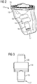
- the further hearing aid component is a receiver and the coil core and the shield have a sound channel passing through the coil antenna.
- Both components can be placed as low as possible in the ear canal to save space.
- an acoustically advantageous placement of the receiver is achieved as close to the eardrum, while the coil antenna is reached close to the IDO hearing instrument of the other (right or left) ear of the user, which positively affects the quality of mutual data transmission.
- the sound channel has the additional advantage that the field lines of the coil antenna thereby additionally compressed in the transmitting and receiving direction and thus the antenna quality is further improved.
- the receiver is an electrodynamic transducer and thus the receiver contains a magnetic circuit which has an excitation winding.
- the receiver is typically fed with a pulse density modulated signal having spectral components in the frequency band of the data transmission system.
- This control is very energy efficient and is therefore used in hearing instruments.
- the spectral components can not be avoided without a strong increase in the energy requirement of the hearing instrument.
- the receiver is the largest consumer in the hearing instrument.
- the energy requirements of the appreciatedtragungssytems is very small and, accordingly, its receiving sensitivity to magnetic interferers is quite large.
- the magnetic circuit and thus also the receiver winding are aligned 90 ° to the antenna. This greatly reduces the coupling of the receiver winding to the antenna.
- the antenna can thus be placed much closer to the receiver.
- the combination of the transversal receiver and the antenna is optimized for the tapered shell contour at the tip of the IDO hearing instrument, minimizing the installation length.
- the placement at the tip of the IDO hearing instrument increases the fitting rate and reduces the size of the hearing instrument.
- more freedom of positioning of the faceplate is possible because the antenna is no longer on or near the faceplate.
- eliminating the effort to place the antenna on or near the faceplate since the tip of the IDO hearing instrument represents a pre-given position. This also eliminates the consideration of physical restrictions, eg of magnetic field disturbances that is required when placed in the area of the faceplate.
- the interference can be reduced to the antenna by using an antenna core, which is additionally provided with a shield between the receiver and antenna.
- the antenna core thus extended to a flange is made entirely of ferrite material or other permeable material.
- the flange preferably covers (best space / performance ratio) the whole area of the receiver. Due to the extended antenna core, the field lines of the excitation winding of the receiver are returned concentrated so that only a very small number of field lines pass through the antenna windings. It is prevented that current is induced in the antenna winding and thus interference from the receiver are greatly reduced.
- the shielding by the antenna core designed as a flange makes additional measures, such as screen foil, and their installation unnecessary.
- Another advantage of the flange is that the antenna quality can be increased. With the same inductance thereby the required number of turns can be reduced, so that in turn the diameter of the single turn, typically enameled copper wire, can be increased.
- the flange may also extend around the edges of the receiver. For this are all four edges of the receiver and their permutations conceivable and bring a more or less large amplification of the decoupling effect.
- a further advantageous development is that the inner wall of the sound channel and / or the side facing away from the coil core of the screen is covered with sound-absorbing material.
- the sound insulation causes a favorable for the use of the receiver vibration decoupling.
- the interference mentioned reduce the performance of the data transmission system sensitive, so that a high bandwidth with low energy consumption is limited achievable.
- the sound channel 17 extends through the coil core 22 and through the shield 26 to the receiver 14.
- the coil core 22 is covered on the inside by a tube 21 formed as a sound-insulating or vibration-damping material.
- the tube 21 surrounds the sound channel 17 from the antenna-side output to the receiver 14 and is there formed parallel to the plate 26 flat.
- the receiver 14 is mounted on the surface-shaped part of the tube 21 and thus also vibration isolated. Round extensions of the sound or vibration damping material are used in addition to the device integrated vibration-decoupled suspension of the device in the housing of the hearing instrument.
- the module can be pre-installed or pre-assembled in the hearing instrument.
- the pre-assembly of the antenna receiver module on the flange formed by the coil core 22 and the tube 21 reduces the assembly effort in the manufacture of the hearing instrument and thus simplifies the manufacturing process.
- a further simplification is achieved in that the coil core 22 is equipped with metallization contacts 38, which serve to contact the antenna 16. Not shown interconnects connect the metallization 38 with the terminals of the antenna 16. For this purpose, further, not shown metallization provided be, with which the winding or windings of the antenna 16 are contacted.
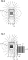
- Fig. 5 the field line distribution of the coil antenna with shield is shown schematically.
- the permeable coil core 22 together with the shield 26, on the one hand shields the region remote from the antenna 16 behind the shield 26.
- a receiver arranged in this region is accordingly shielded by the shield 26 from interference signals from the antenna protected.
- the field line density is increased in the axial direction on the opposite side of the shield 26 of the antenna, and thus in the transmitting and receiving direction of the antenna.
- the coil core 22 with integrally formed shield 26 accordingly effects a field characteristic optimized for the transmission and reception of data in the axial direction. This effect would be additionally increased if, which is not the case in the illustrated simulation, the spool core 22 has a through opening, for example the sound channel explained above.
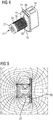
- Fig. 6 the field line profile of a receiver coil working receiver is shown schematically.
- the receiver coil 23 is arranged axially, that is, oriented in the longitudinal direction. It can be seen that the receiver coil 23 generates a strongly compressed (magnetic) field in the axial direction, while it generates a relatively weak (magnetic) field in the radial direction, that is, in the figure to the right and left.
- Fig. 7 the field line profile of the receiver is shown with shielding.
- the receiver 14 is arranged in the figure on the right of the above-described shield 26 of the permeable coil core 22.
- the coil core 22 carries the antenna 16.
- Previously explained metallization contacts 38 are integrated in the coil core 22 and serve to electrically contact the antenna 16.
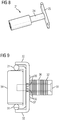
- FIG. 9 a further embodiment of the antenna receiver module is shown.
- the spool core 32 is formed as described above on one side as a screen 37.
- An antenna 36 is wound on the spool core 32.
- Metallization contacts 38 are used for electrical contacting of the antenna.
- the spool core 32 surrounds the receiver 34 arranged there, at least in the region shown in the figure above and below.
- the shield 37 or the coil core 32 is designed cup-shaped there, so that the receiver 34 surrounded by the coil core 32 and the shield 37 at least in a region of the shield periphery in the direction away from the antenna 36 direction.
Landscapes
- Engineering & Computer Science (AREA)
- Physics & Mathematics (AREA)
- Health & Medical Sciences (AREA)
- General Health & Medical Sciences (AREA)
- Neurosurgery (AREA)
- Otolaryngology (AREA)
- Acoustics & Sound (AREA)
- Signal Processing (AREA)
- Computer Networks & Wireless Communication (AREA)
- Headphones And Earphones (AREA)
- Shielding Devices Or Components To Electric Or Magnetic Fields (AREA)
- Circuit For Audible Band Transducer (AREA)
- Details Of Aerials (AREA)
Claims (8)
- Dispositif d'antenne destiné à un appareil auditif (13),
comportant un système d'antenne (16, 36), qui présente une direction spatiale d'émission et de réception préférée, et comportant un autre composant d'appareil auditif électrique, qui émet un rayonnement électromagnétique parasite principalement dans une direction spatiale de rayonnement parasite,- le système d'antenne (16, 36) et l'autre composant d'appareil auditif sont disposés de telle manière que la direction spatiale d'émission et de réception et la direction spatiale de rayonnement parasite sont orientés transversalement l'un à l'autre de manière à réduire une injection de rayonnement parasite dans le système d'antenne (16, 36),caractérisé en ce que
le dispositif d'antenne (16, 36) comporte un noyau de bobine (22, 32) constitué de matériau magnétiquement perméable, qui est formé au niveau d'une extrémité sur un écran au moins partiellement plat (26, 37) et qui est disposé transversalement à une direction spatiale d'émission et de réception du système d'antenne (16, 36), en ce que
l'autre composant d'appareil auditif est un récepteur (14, 34) et en ce que
le noyau de bobine (22, 32) et le blindage (26, 37) comportent un canal acoustique (17) traversant. - Dispositif d'antenne selon la revendication 1,
caractérisé en ce que le système d'antenne (16, 36) comprend une antenne à bobine, en ce que l'autre composant d'appareil auditif comprend un système de bobines (23) qui émet le rayonnement parasite et en ce que l'antenne à bobine et le système de bobines (23) sont orientés transversalement l'un à l'autre par rapport à leur direction longitudinale respective. - Dispositif d'antenne selon la revendication 1 ou 2,
caractérisé en ce que l'autre composant d'appareil auditif est disposé sur l'écran (26, 37). - Dispositif d'antenne selon l'une quelconque des revendications précédentes,
caractérisé en ce que l'autre composant d'appareil auditif est fixé à l'écran (26, 37). - Dispositif d'antenne selon la revendication l'une quelconque des revendications précédentes,
caractérisé en ce que l'écran (26, 37) entoure, dans au moins une région de sa circonférence, l'autre composant d'appareil auditif, dans la direction opposée au système d'antenne (16, 36). - Dispositif d'antenne selon l'une quelconque des revendications précédentes,
caractérisé en ce que le noyau de bobine (22, 32) et/ou l'écran (26, 37) comporte des contacts de métallisation (38) destinés à être mis en contact électrique avec le dispositif d'antenne (16, 36). - Dispositif d'antenne selon l'une quelconque des revendications précédentes, caractérisé en ce que la paroi intérieure du canal acoustique (17) et/ou la face de l'écran (26, 37) opposée au noyau de bobine (22, 32) est/sont revêtue(s) de matériau d'amortissement acoustique.
- Appareil auditif comportant un dispositif d'antenne selon l'une quelconque des revendications précédentes.
Applications Claiming Priority (1)
| Application Number | Priority Date | Filing Date | Title |
|---|---|---|---|
| DE102013210689.0A DE102013210689B3 (de) | 2013-06-07 | 2013-06-07 | Antenneneinrichtung für Hörinstrumente |
Publications (2)
| Publication Number | Publication Date |
|---|---|
| EP2811761A1 EP2811761A1 (fr) | 2014-12-10 |
| EP2811761B1 true EP2811761B1 (fr) | 2019-05-08 |
Family
ID=50189623
Family Applications (1)
| Application Number | Title | Priority Date | Filing Date |
|---|---|---|---|
| EP14157657.9A Revoked EP2811761B1 (fr) | 2013-06-07 | 2014-03-04 | Dispositif d'antenne pour appareils auditifs |
Country Status (6)
| Country | Link |
|---|---|
| US (1) | US9521494B2 (fr) |
| EP (1) | EP2811761B1 (fr) |
| CN (1) | CN104244156B (fr) |
| AU (1) | AU2014202868B2 (fr) |
| DE (1) | DE102013210689B3 (fr) |
| DK (1) | DK2811761T3 (fr) |
Families Citing this family (19)
| Publication number | Priority date | Publication date | Assignee | Title |
|---|---|---|---|---|
| DE102014200524A1 (de) | 2014-01-14 | 2015-07-16 | Siemens Medical Instruments Pte. Ltd. | Antenneneinrichtung für Hörinstrumente |
| EP3269155B1 (fr) * | 2015-03-13 | 2019-01-02 | Sivantos Pte. Ltd. | Système d'aide auditive binaurale |
| US10321248B2 (en) * | 2015-06-03 | 2019-06-11 | Gn Hearing A/S | Hearing device shell with guide structure |
| US9661426B2 (en) | 2015-06-22 | 2017-05-23 | Gn Hearing A/S | Hearing aid having combined antennas |
| DK3110174T3 (da) * | 2015-06-24 | 2021-04-12 | Oticon As | Høreanordning indbefattende antenneenhed og afskærmet transmissionslinje |
| DE102016202658A1 (de) * | 2016-02-22 | 2017-08-24 | Sivantos Pte. Ltd. | Lautsprechermodul für ein Hörgerät und Hörgerät |
| WO2017153274A1 (fr) * | 2016-03-07 | 2017-09-14 | Sivantos Pte. Ltd. | Antenne |
| WO2018113920A1 (fr) * | 2016-12-20 | 2018-06-28 | Sonova Ag | Appareil auditif de type prothèse contour d'oreille comprenant une antenne de ligne de transmission à extrémité ouverte |
| EP3343954B1 (fr) * | 2016-12-29 | 2023-05-31 | Oticon A/s | Dispositif auditif avec une partie d'antenne externe ainsi qu'une partie d'antenne interne |
| DE102017210447A1 (de) * | 2017-06-21 | 2018-12-27 | Sivantos Pte. Ltd. | Hörgerät |
| DE102017215372A1 (de) * | 2017-09-01 | 2019-03-07 | Sivantos Pte. Ltd. | Hörgerät |
| US10511920B2 (en) | 2018-04-13 | 2019-12-17 | Starkey Laboratories, Inc. | Ear-worn electronic device incorporating directional magnetic antenna |
| DE102018209189A1 (de) * | 2018-06-08 | 2019-12-12 | Sivantos Pte. Ltd. | Antenne sowie Gerät mit einer solchen Antenne |
| WO2020028084A1 (fr) | 2018-07-31 | 2020-02-06 | Earlens Corporation | Facteur de qualité dans un système auditif à contact |
| WO2021003366A1 (fr) * | 2019-07-03 | 2021-01-07 | Starkey Laboratories, Inc. | Antenne en spirale à polarisation circulaire pour dispositifs d'aide auditive |
| EP3806493B1 (fr) * | 2019-10-11 | 2023-07-19 | GN Hearing A/S | Dispositif auditif doté d'une bobine d'induction magnétique |
| DE102019217861B3 (de) * | 2019-11-20 | 2021-05-20 | Sivantos Pte. Ltd. | Hörgerät |
| DE102020201480A1 (de) | 2020-02-06 | 2021-08-12 | Sivantos Pte. Ltd. | Hörgerät |
| CA3222663A1 (fr) * | 2021-09-17 | 2023-03-23 | Stryker Corporation | Systeme de localisation d'appareils de support de patient |
Citations (14)
| Publication number | Priority date | Publication date | Assignee | Title |
|---|---|---|---|---|
| US5640457A (en) | 1995-11-13 | 1997-06-17 | Gnecco; Louis Thomas | Electromagnetically shielded hearing aid |
| US20040028251A1 (en) | 2002-08-12 | 2004-02-12 | Siemens Audiologische Technik Gmbh | Space-saving antenna arrangement for hearing aid device |
| US20050162331A1 (en) | 2002-01-17 | 2005-07-28 | Takanori Endo | Antenna for reader/writer and reader/writer having the antenna |
| US20050168396A1 (en) | 2004-01-30 | 2005-08-04 | Victorian Thomas A. | Method and apparatus for a wireless hearing aid antenna |
| US20050244024A1 (en) | 2004-04-13 | 2005-11-03 | Thomas Fischer | Hearing aid with a resonator carried by the hearing aid housing |
| US20060018495A1 (en) | 2004-07-20 | 2006-01-26 | Onno Geschiere | Radio frequency shielding for receivers within hearing aids and listening devices |
| US20080212812A1 (en) | 2007-02-16 | 2008-09-04 | Hoong Yih Chan | Hearing apparatus having a receiver compensation coil |
| US20080226108A1 (en) | 2006-09-19 | 2008-09-18 | Markus Heerlein | Receiver with an additional shielding facility |
| US20090274328A1 (en) | 2008-05-05 | 2009-11-05 | Volker Gebhardt | Apparatus and method for reducing interference effects in the case of a wireless data transmission in hearing device applications |
| US20090315553A1 (en) | 2006-02-20 | 2009-12-24 | Smart Co., Ltd. | Axially Symmetric Vertical Magnetic Field Component Exciting Sensor System |
| US20100195857A1 (en) | 2009-02-03 | 2010-08-05 | Siemens Medical Instruments Pte. Ltd. | Hearing aid with interference compensation and method for configurating the hearing aid |
| EP2278828A2 (fr) | 2009-07-23 | 2011-01-26 | Starkey Laboratories, Inc. | Procédé et appareil pour blindage électromagnétique isolé pour une utilisation dans des dispositifs d'assistance auditive |
| US20110194717A1 (en) | 2008-09-26 | 2011-08-11 | Oticon A/S | Hearing aid with exchangeable shell parts and wireless communication |
| US20130064406A1 (en) | 2011-09-09 | 2013-03-14 | Thomas E. Miller | Rf shielding for acoustic devices |
Family Cites Families (5)
| Publication number | Priority date | Publication date | Assignee | Title |
|---|---|---|---|---|
| EP1719384B1 (fr) * | 2004-02-19 | 2011-05-04 | Oticon A/S | Appareil auditif equipé d'une antenne destinée à l'emission et à la reception de signaux électromagnétiques et batterie blindante |
| EP1788592B1 (fr) * | 2005-11-17 | 2012-01-11 | Oticon A/S | Bobine blindée pour des applications sans fil inductives |
| US20130188803A1 (en) * | 2012-01-20 | 2013-07-25 | Qualcomm Incorporated | Earpiece |
| DK3151585T3 (en) * | 2012-03-16 | 2018-09-24 | Sonova Ag | ANTENNA MODULE FOR A HEARING, EARRING AND HEARING PROVIDED WITH SUCH ANTENNA MODULE |
| US9237404B2 (en) * | 2012-12-28 | 2016-01-12 | Gn Resound A/S | Dipole antenna for a hearing aid |
-
2013
- 2013-06-07 DE DE102013210689.0A patent/DE102013210689B3/de active Active
-
2014
- 2014-03-04 EP EP14157657.9A patent/EP2811761B1/fr not_active Revoked
- 2014-03-04 DK DK14157657.9T patent/DK2811761T3/da active
- 2014-05-27 AU AU2014202868A patent/AU2014202868B2/en not_active Ceased
- 2014-06-06 CN CN201410250412.0A patent/CN104244156B/zh active Active
- 2014-06-09 US US14/299,144 patent/US9521494B2/en active Active
Patent Citations (14)
| Publication number | Priority date | Publication date | Assignee | Title |
|---|---|---|---|---|
| US5640457A (en) | 1995-11-13 | 1997-06-17 | Gnecco; Louis Thomas | Electromagnetically shielded hearing aid |
| US20050162331A1 (en) | 2002-01-17 | 2005-07-28 | Takanori Endo | Antenna for reader/writer and reader/writer having the antenna |
| US20040028251A1 (en) | 2002-08-12 | 2004-02-12 | Siemens Audiologische Technik Gmbh | Space-saving antenna arrangement for hearing aid device |
| US20050168396A1 (en) | 2004-01-30 | 2005-08-04 | Victorian Thomas A. | Method and apparatus for a wireless hearing aid antenna |
| US20050244024A1 (en) | 2004-04-13 | 2005-11-03 | Thomas Fischer | Hearing aid with a resonator carried by the hearing aid housing |
| US20060018495A1 (en) | 2004-07-20 | 2006-01-26 | Onno Geschiere | Radio frequency shielding for receivers within hearing aids and listening devices |
| US20090315553A1 (en) | 2006-02-20 | 2009-12-24 | Smart Co., Ltd. | Axially Symmetric Vertical Magnetic Field Component Exciting Sensor System |
| US20080226108A1 (en) | 2006-09-19 | 2008-09-18 | Markus Heerlein | Receiver with an additional shielding facility |
| US20080212812A1 (en) | 2007-02-16 | 2008-09-04 | Hoong Yih Chan | Hearing apparatus having a receiver compensation coil |
| US20090274328A1 (en) | 2008-05-05 | 2009-11-05 | Volker Gebhardt | Apparatus and method for reducing interference effects in the case of a wireless data transmission in hearing device applications |
| US20110194717A1 (en) | 2008-09-26 | 2011-08-11 | Oticon A/S | Hearing aid with exchangeable shell parts and wireless communication |
| US20100195857A1 (en) | 2009-02-03 | 2010-08-05 | Siemens Medical Instruments Pte. Ltd. | Hearing aid with interference compensation and method for configurating the hearing aid |
| EP2278828A2 (fr) | 2009-07-23 | 2011-01-26 | Starkey Laboratories, Inc. | Procédé et appareil pour blindage électromagnétique isolé pour une utilisation dans des dispositifs d'assistance auditive |
| US20130064406A1 (en) | 2011-09-09 | 2013-03-14 | Thomas E. Miller | Rf shielding for acoustic devices |
Non-Patent Citations (1)
| Title |
|---|
| "Principles of Inductive Near Field Communications for Internet of Things", 2011, article JOHNSON IHYEH AGBINYA: "6 Circuit models and power estimates of antennas in inductive near field communications links", pages: 65 - 76, XP055684248 |
Also Published As
| Publication number | Publication date |
|---|---|
| AU2014202868A1 (en) | 2015-01-15 |
| US9521494B2 (en) | 2016-12-13 |
| CN104244156A (zh) | 2014-12-24 |
| US20140363037A1 (en) | 2014-12-11 |
| DK2811761T3 (da) | 2019-08-12 |
| AU2014202868B2 (en) | 2015-12-10 |
| DE102013210689B3 (de) | 2014-10-02 |
| EP2811761A1 (fr) | 2014-12-10 |
| CN104244156B (zh) | 2017-10-13 |
Similar Documents
| Publication | Publication Date | Title |
|---|---|---|
| EP2811761B1 (fr) | Dispositif d'antenne pour appareils auditifs | |
| EP2894880B1 (fr) | Dispositif d'antenne pour appareils auditifs | |
| EP2782363B1 (fr) | Appareillage auditif binaural et écouteur | |
| US10231063B2 (en) | Binaural hearing aid system | |
| US10021495B2 (en) | Antenna for hearing device, ear tip and hearing device provided with such an antenna | |
| EP3413587B1 (fr) | Appareil auditif, en particulier appareil de correction auditive derrière l'oreille | |
| DE102008015263B4 (de) | Hörsystem mit Teilbandsignalaustausch und entsprechendes Verfahren | |
| US20190268708A1 (en) | Hearing device including an external antenna part and an internal antenna part | |
| EP3209032B1 (fr) | Module de haut-parleur pour un appareil auditif et appareil auditif | |
| EP3567672B1 (fr) | Appareil d'aide auditive pourvu de cadre électronique et d'antenne intégrée audit appareil | |
| EP2375784B1 (fr) | Appareil auditif doté d'un blindage de haut-parleur amorphe | |
| DE102017012195B4 (de) | Hörgerät, insbesondere Hinter-dem-Ohr-Hörhilfegerät | |
| DE102004050616B3 (de) | Hörhilfe mit Signalkopplung und entsprechendes Verfahren | |
| EP1915030B1 (fr) | Appareil auditif doté d'une boucle en métal conducteur de courant | |
| DE102017220187A1 (de) | Hörhilfegerät | |
| US11924615B2 (en) | Hearing aid, antenna for a hearing aid, and method for producing a hearing aid | |
| DE102010012946B4 (de) | Hörgerät mit amorpher Lautsprecherabschirmung | |
| EP3739906A1 (fr) | Instrument auditif | |
| DE102010026378A1 (de) | Kommunikationsmodul für ein Hörinstrument | |
| DE102009008618A1 (de) | Hörvorrichtung mit zwei elektrischen Einheiten, die über Drähte mit einander verbunden sind. |
Legal Events
| Date | Code | Title | Description |
|---|---|---|---|
| PUAI | Public reference made under article 153(3) epc to a published international application that has entered the european phase |
Free format text: ORIGINAL CODE: 0009012 |
|
| 17P | Request for examination filed |
Effective date: 20140304 |
|
| AK | Designated contracting states |
Kind code of ref document: A1 Designated state(s): AL AT BE BG CH CY CZ DE DK EE ES FI FR GB GR HR HU IE IS IT LI LT LU LV MC MK MT NL NO PL PT RO RS SE SI SK SM TR |
|
| AX | Request for extension of the european patent |
Extension state: BA ME |
|
| R17P | Request for examination filed (corrected) |
Effective date: 20150610 |
|
| RBV | Designated contracting states (corrected) |
Designated state(s): AL AT BE BG CH CY CZ DE DK EE ES FI FR GB GR HR HU IE IS IT LI LT LU LV MC MK MT NL NO PL PT RO RS SE SI SK SM TR |
|
| RAP1 | Party data changed (applicant data changed or rights of an application transferred) |
Owner name: SIVANTOS PTE. LTD. |
|
| STAA | Information on the status of an ep patent application or granted ep patent |
Free format text: STATUS: EXAMINATION IS IN PROGRESS |
|
| RAP1 | Party data changed (applicant data changed or rights of an application transferred) |
Owner name: SIVANTOS PTE. LTD. |
|
| 17Q | First examination report despatched |
Effective date: 20180219 |
|
| RIC1 | Information provided on ipc code assigned before grant |
Ipc: H01Q 7/00 20060101ALI20180928BHEP Ipc: H01Q 1/27 20060101ALI20180928BHEP Ipc: H04R 25/00 20060101AFI20180928BHEP |
|
| GRAP | Despatch of communication of intention to grant a patent |
Free format text: ORIGINAL CODE: EPIDOSNIGR1 |
|
| STAA | Information on the status of an ep patent application or granted ep patent |
Free format text: STATUS: GRANT OF PATENT IS INTENDED |
|
| RIC1 | Information provided on ipc code assigned before grant |
Ipc: H01Q 1/22 20060101ALI20181018BHEP Ipc: H01Q 1/27 20060101ALI20181018BHEP Ipc: H01Q 7/00 20060101ALI20181018BHEP Ipc: H04R 25/00 20060101AFI20181018BHEP |
|
| INTG | Intention to grant announced |
Effective date: 20181120 |
|
| GRAS | Grant fee paid |
Free format text: ORIGINAL CODE: EPIDOSNIGR3 |
|
| GRAA | (expected) grant |
Free format text: ORIGINAL CODE: 0009210 |
|
| STAA | Information on the status of an ep patent application or granted ep patent |
Free format text: STATUS: THE PATENT HAS BEEN GRANTED |
|
| AK | Designated contracting states |
Kind code of ref document: B1 Designated state(s): AL AT BE BG CH CY CZ DE DK EE ES FI FR GB GR HR HU IE IS IT LI LT LU LV MC MK MT NL NO PL PT RO RS SE SI SK SM TR |
|
| REG | Reference to a national code |
Ref country code: GB Ref legal event code: FG4D Free format text: NOT ENGLISH |
|
| REG | Reference to a national code |
Ref country code: CH Ref legal event code: EP Ref country code: AT Ref legal event code: REF Ref document number: 1132100 Country of ref document: AT Kind code of ref document: T Effective date: 20190515 |
|
| REG | Reference to a national code |
Ref country code: DE Ref legal event code: R096 Ref document number: 502014011632 Country of ref document: DE |
|
| REG | Reference to a national code |
Ref country code: IE Ref legal event code: FG4D Free format text: LANGUAGE OF EP DOCUMENT: GERMAN |
|
| REG | Reference to a national code |
Ref country code: CH Ref legal event code: NV Representative=s name: E. BLUM AND CO. AG PATENT- UND MARKENANWAELTE , CH |
|
| REG | Reference to a national code |
Ref country code: DK Ref legal event code: T3 Effective date: 20190807 |
|
| REG | Reference to a national code |
Ref country code: NL Ref legal event code: MP Effective date: 20190508 |
|
| REG | Reference to a national code |
Ref country code: LT Ref legal event code: MG4D |
|
| PG25 | Lapsed in a contracting state [announced via postgrant information from national office to epo] |
Ref country code: FI Free format text: LAPSE BECAUSE OF FAILURE TO SUBMIT A TRANSLATION OF THE DESCRIPTION OR TO PAY THE FEE WITHIN THE PRESCRIBED TIME-LIMIT Effective date: 20190508 Ref country code: NO Free format text: LAPSE BECAUSE OF FAILURE TO SUBMIT A TRANSLATION OF THE DESCRIPTION OR TO PAY THE FEE WITHIN THE PRESCRIBED TIME-LIMIT Effective date: 20190808 Ref country code: SE Free format text: LAPSE BECAUSE OF FAILURE TO SUBMIT A TRANSLATION OF THE DESCRIPTION OR TO PAY THE FEE WITHIN THE PRESCRIBED TIME-LIMIT Effective date: 20190508 Ref country code: ES Free format text: LAPSE BECAUSE OF FAILURE TO SUBMIT A TRANSLATION OF THE DESCRIPTION OR TO PAY THE FEE WITHIN THE PRESCRIBED TIME-LIMIT Effective date: 20190508 Ref country code: PT Free format text: LAPSE BECAUSE OF FAILURE TO SUBMIT A TRANSLATION OF THE DESCRIPTION OR TO PAY THE FEE WITHIN THE PRESCRIBED TIME-LIMIT Effective date: 20190908 Ref country code: NL Free format text: LAPSE BECAUSE OF FAILURE TO SUBMIT A TRANSLATION OF THE DESCRIPTION OR TO PAY THE FEE WITHIN THE PRESCRIBED TIME-LIMIT Effective date: 20190508 Ref country code: AL Free format text: LAPSE BECAUSE OF FAILURE TO SUBMIT A TRANSLATION OF THE DESCRIPTION OR TO PAY THE FEE WITHIN THE PRESCRIBED TIME-LIMIT Effective date: 20190508 Ref country code: LT Free format text: LAPSE BECAUSE OF FAILURE TO SUBMIT A TRANSLATION OF THE DESCRIPTION OR TO PAY THE FEE WITHIN THE PRESCRIBED TIME-LIMIT Effective date: 20190508 Ref country code: HR Free format text: LAPSE BECAUSE OF FAILURE TO SUBMIT A TRANSLATION OF THE DESCRIPTION OR TO PAY THE FEE WITHIN THE PRESCRIBED TIME-LIMIT Effective date: 20190508 |
|
| PG25 | Lapsed in a contracting state [announced via postgrant information from national office to epo] |
Ref country code: BG Free format text: LAPSE BECAUSE OF FAILURE TO SUBMIT A TRANSLATION OF THE DESCRIPTION OR TO PAY THE FEE WITHIN THE PRESCRIBED TIME-LIMIT Effective date: 20190808 Ref country code: GR Free format text: LAPSE BECAUSE OF FAILURE TO SUBMIT A TRANSLATION OF THE DESCRIPTION OR TO PAY THE FEE WITHIN THE PRESCRIBED TIME-LIMIT Effective date: 20190809 Ref country code: RS Free format text: LAPSE BECAUSE OF FAILURE TO SUBMIT A TRANSLATION OF THE DESCRIPTION OR TO PAY THE FEE WITHIN THE PRESCRIBED TIME-LIMIT Effective date: 20190508 Ref country code: LV Free format text: LAPSE BECAUSE OF FAILURE TO SUBMIT A TRANSLATION OF THE DESCRIPTION OR TO PAY THE FEE WITHIN THE PRESCRIBED TIME-LIMIT Effective date: 20190508 |
|
| PG25 | Lapsed in a contracting state [announced via postgrant information from national office to epo] |
Ref country code: CZ Free format text: LAPSE BECAUSE OF FAILURE TO SUBMIT A TRANSLATION OF THE DESCRIPTION OR TO PAY THE FEE WITHIN THE PRESCRIBED TIME-LIMIT Effective date: 20190508 Ref country code: RO Free format text: LAPSE BECAUSE OF FAILURE TO SUBMIT A TRANSLATION OF THE DESCRIPTION OR TO PAY THE FEE WITHIN THE PRESCRIBED TIME-LIMIT Effective date: 20190508 Ref country code: EE Free format text: LAPSE BECAUSE OF FAILURE TO SUBMIT A TRANSLATION OF THE DESCRIPTION OR TO PAY THE FEE WITHIN THE PRESCRIBED TIME-LIMIT Effective date: 20190508 Ref country code: SK Free format text: LAPSE BECAUSE OF FAILURE TO SUBMIT A TRANSLATION OF THE DESCRIPTION OR TO PAY THE FEE WITHIN THE PRESCRIBED TIME-LIMIT Effective date: 20190508 |
|
| REG | Reference to a national code |
Ref country code: DE Ref legal event code: R026 Ref document number: 502014011632 Country of ref document: DE |
|
| PLBI | Opposition filed |
Free format text: ORIGINAL CODE: 0009260 |
|
| PLAX | Notice of opposition and request to file observation + time limit sent |
Free format text: ORIGINAL CODE: EPIDOSNOBS2 |
|
| PG25 | Lapsed in a contracting state [announced via postgrant information from national office to epo] |
Ref country code: IT Free format text: LAPSE BECAUSE OF FAILURE TO SUBMIT A TRANSLATION OF THE DESCRIPTION OR TO PAY THE FEE WITHIN THE PRESCRIBED TIME-LIMIT Effective date: 20190508 Ref country code: SM Free format text: LAPSE BECAUSE OF FAILURE TO SUBMIT A TRANSLATION OF THE DESCRIPTION OR TO PAY THE FEE WITHIN THE PRESCRIBED TIME-LIMIT Effective date: 20190508 |
|
| PLAB | Opposition data, opponent's data or that of the opponent's representative modified |
Free format text: ORIGINAL CODE: 0009299OPPO |
|
| 26 | Opposition filed |
Opponent name: GN HEARING A/S / OTICON A/S Effective date: 20200210 |
|
| PG25 | Lapsed in a contracting state [announced via postgrant information from national office to epo] |
Ref country code: TR Free format text: LAPSE BECAUSE OF FAILURE TO SUBMIT A TRANSLATION OF THE DESCRIPTION OR TO PAY THE FEE WITHIN THE PRESCRIBED TIME-LIMIT Effective date: 20190508 |
|
| R26 | Opposition filed (corrected) |
Opponent name: GN HEARING A/S Effective date: 20200210 |
|
| PG25 | Lapsed in a contracting state [announced via postgrant information from national office to epo] |
Ref country code: PL Free format text: LAPSE BECAUSE OF FAILURE TO SUBMIT A TRANSLATION OF THE DESCRIPTION OR TO PAY THE FEE WITHIN THE PRESCRIBED TIME-LIMIT Effective date: 20190508 |
|
| PG25 | Lapsed in a contracting state [announced via postgrant information from national office to epo] |
Ref country code: SI Free format text: LAPSE BECAUSE OF FAILURE TO SUBMIT A TRANSLATION OF THE DESCRIPTION OR TO PAY THE FEE WITHIN THE PRESCRIBED TIME-LIMIT Effective date: 20190508 |
|
| PLBB | Reply of patent proprietor to notice(s) of opposition received |
Free format text: ORIGINAL CODE: EPIDOSNOBS3 |
|
| PG25 | Lapsed in a contracting state [announced via postgrant information from national office to epo] |
Ref country code: MC Free format text: LAPSE BECAUSE OF FAILURE TO SUBMIT A TRANSLATION OF THE DESCRIPTION OR TO PAY THE FEE WITHIN THE PRESCRIBED TIME-LIMIT Effective date: 20190508 |
|
| REG | Reference to a national code |
Ref country code: BE Ref legal event code: MM Effective date: 20200331 |
|
| PG25 | Lapsed in a contracting state [announced via postgrant information from national office to epo] |
Ref country code: LU Free format text: LAPSE BECAUSE OF NON-PAYMENT OF DUE FEES Effective date: 20200304 |
|
| PG25 | Lapsed in a contracting state [announced via postgrant information from national office to epo] |
Ref country code: IE Free format text: LAPSE BECAUSE OF NON-PAYMENT OF DUE FEES Effective date: 20200304 |
|
| PG25 | Lapsed in a contracting state [announced via postgrant information from national office to epo] |
Ref country code: BE Free format text: LAPSE BECAUSE OF NON-PAYMENT OF DUE FEES Effective date: 20200331 |
|
| PLCK | Communication despatched that opposition was rejected |
Free format text: ORIGINAL CODE: EPIDOSNREJ1 |
|
| REG | Reference to a national code |
Ref country code: AT Ref legal event code: MM01 Ref document number: 1132100 Country of ref document: AT Kind code of ref document: T Effective date: 20200304 |
|
| APBM | Appeal reference recorded |
Free format text: ORIGINAL CODE: EPIDOSNREFNO |
|
| APBP | Date of receipt of notice of appeal recorded |
Free format text: ORIGINAL CODE: EPIDOSNNOA2O |
|
| APAH | Appeal reference modified |
Free format text: ORIGINAL CODE: EPIDOSCREFNO |
|
| APBQ | Date of receipt of statement of grounds of appeal recorded |
Free format text: ORIGINAL CODE: EPIDOSNNOA3O |
|
| PG25 | Lapsed in a contracting state [announced via postgrant information from national office to epo] |
Ref country code: AT Free format text: LAPSE BECAUSE OF NON-PAYMENT OF DUE FEES Effective date: 20200304 |
|
| PG25 | Lapsed in a contracting state [announced via postgrant information from national office to epo] |
Ref country code: MT Free format text: LAPSE BECAUSE OF FAILURE TO SUBMIT A TRANSLATION OF THE DESCRIPTION OR TO PAY THE FEE WITHIN THE PRESCRIBED TIME-LIMIT Effective date: 20190508 Ref country code: CY Free format text: LAPSE BECAUSE OF FAILURE TO SUBMIT A TRANSLATION OF THE DESCRIPTION OR TO PAY THE FEE WITHIN THE PRESCRIBED TIME-LIMIT Effective date: 20190508 |
|
| PG25 | Lapsed in a contracting state [announced via postgrant information from national office to epo] |
Ref country code: MK Free format text: LAPSE BECAUSE OF FAILURE TO SUBMIT A TRANSLATION OF THE DESCRIPTION OR TO PAY THE FEE WITHIN THE PRESCRIBED TIME-LIMIT Effective date: 20190508 Ref country code: IS Free format text: LAPSE BECAUSE OF FAILURE TO SUBMIT A TRANSLATION OF THE DESCRIPTION OR TO PAY THE FEE WITHIN THE PRESCRIBED TIME-LIMIT Effective date: 20190908 |
|
| PGFP | Annual fee paid to national office [announced via postgrant information from national office to epo] |
Ref country code: FR Payment date: 20230320 Year of fee payment: 10 Ref country code: DK Payment date: 20230323 Year of fee payment: 10 |
|
| PGFP | Annual fee paid to national office [announced via postgrant information from national office to epo] |
Ref country code: GB Payment date: 20230323 Year of fee payment: 10 Ref country code: DE Payment date: 20230320 Year of fee payment: 10 |
|
| PGFP | Annual fee paid to national office [announced via postgrant information from national office to epo] |
Ref country code: CH Payment date: 20230402 Year of fee payment: 10 |
|
| REG | Reference to a national code |
Ref country code: DE Ref legal event code: R103 Ref document number: 502014011632 Country of ref document: DE Ref country code: DE Ref legal event code: R064 Ref document number: 502014011632 Country of ref document: DE |
|
| APBU | Appeal procedure closed |
Free format text: ORIGINAL CODE: EPIDOSNNOA9O |
|
| RDAD | Information modified related to despatch of communication that patent is revoked |
Free format text: ORIGINAL CODE: EPIDOSCREV1 |
|
| RDAF | Communication despatched that patent is revoked |
Free format text: ORIGINAL CODE: EPIDOSNREV1 |
|
| RDAG | Patent revoked |
Free format text: ORIGINAL CODE: 0009271 |
|
| STAA | Information on the status of an ep patent application or granted ep patent |
Free format text: STATUS: PATENT REVOKED |
|
| REG | Reference to a national code |
Ref country code: CH Ref legal event code: PL |
|
| 27W | Patent revoked |
Effective date: 20230921 |
|
| GBPR | Gb: patent revoked under art. 102 of the ep convention designating the uk as contracting state |
Effective date: 20230921 |
|
| REG | Reference to a national code |
Ref country code: AT Ref legal event code: MA03 Ref document number: 1132100 Country of ref document: AT Kind code of ref document: T Effective date: 20230921 |