EP3209032B1 - Module de haut-parleur pour un appareil auditif et appareil auditif - Google Patents
Module de haut-parleur pour un appareil auditif et appareil auditif Download PDFInfo
- Publication number
- EP3209032B1 EP3209032B1 EP17150204.0A EP17150204A EP3209032B1 EP 3209032 B1 EP3209032 B1 EP 3209032B1 EP 17150204 A EP17150204 A EP 17150204A EP 3209032 B1 EP3209032 B1 EP 3209032B1
- Authority
- EP
- European Patent Office
- Prior art keywords
- antenna
- coil
- loudspeaker
- housing
- hearing aid
- Prior art date
- Legal status (The legal status is an assumption and is not a legal conclusion. Google has not performed a legal analysis and makes no representation as to the accuracy of the status listed.)
- Active
Links
- 239000003302 ferromagnetic material Substances 0.000 claims description 5
- 230000005294 ferromagnetic effect Effects 0.000 claims description 3
- 239000002902 ferrimagnetic material Substances 0.000 claims description 2
- 230000005291 magnetic effect Effects 0.000 description 28
- 230000005540 biological transmission Effects 0.000 description 11
- 239000012528 membrane Substances 0.000 description 11
- 230000005236 sound signal Effects 0.000 description 8
- 230000000694 effects Effects 0.000 description 7
- 206010011878 Deafness Diseases 0.000 description 4
- 230000008878 coupling Effects 0.000 description 4
- 238000010168 coupling process Methods 0.000 description 4
- 238000005859 coupling reaction Methods 0.000 description 4
- 238000011161 development Methods 0.000 description 4
- 230000018109 developmental process Effects 0.000 description 4
- 230000010370 hearing loss Effects 0.000 description 4
- 231100000888 hearing loss Toxicity 0.000 description 4
- 208000016354 hearing loss disease Diseases 0.000 description 4
- 229910000859 α-Fe Inorganic materials 0.000 description 4
- 238000009434 installation Methods 0.000 description 3
- 210000003454 tympanic membrane Anatomy 0.000 description 3
- 239000012790 adhesive layer Substances 0.000 description 2
- 238000013016 damping Methods 0.000 description 2
- 210000005069 ears Anatomy 0.000 description 2
- 230000006872 improvement Effects 0.000 description 2
- 230000010354 integration Effects 0.000 description 2
- 230000010355 oscillation Effects 0.000 description 2
- 230000009467 reduction Effects 0.000 description 2
- 208000009205 Tinnitus Diseases 0.000 description 1
- 210000000988 bone and bone Anatomy 0.000 description 1
- 230000008859 change Effects 0.000 description 1
- 238000010276 construction Methods 0.000 description 1
- 230000001419 dependent effect Effects 0.000 description 1
- 230000005684 electric field Effects 0.000 description 1
- 230000007613 environmental effect Effects 0.000 description 1
- 230000002349 favourable effect Effects 0.000 description 1
- 230000005293 ferrimagnetic effect Effects 0.000 description 1
- 238000001914 filtration Methods 0.000 description 1
- 239000011888 foil Substances 0.000 description 1
- 210000003128 head Anatomy 0.000 description 1
- 239000007943 implant Substances 0.000 description 1
- 230000006698 induction Effects 0.000 description 1
- 230000002452 interceptive effect Effects 0.000 description 1
- 230000005415 magnetization Effects 0.000 description 1
- 239000000463 material Substances 0.000 description 1
- 238000012216 screening Methods 0.000 description 1
- 230000008054 signal transmission Effects 0.000 description 1
- 125000006850 spacer group Chemical group 0.000 description 1
- 230000000638 stimulation Effects 0.000 description 1
- 231100000886 tinnitus Toxicity 0.000 description 1
- 210000001519 tissue Anatomy 0.000 description 1
Images


Classifications
-
- H—ELECTRICITY
- H04—ELECTRIC COMMUNICATION TECHNIQUE
- H04R—LOUDSPEAKERS, MICROPHONES, GRAMOPHONE PICK-UPS OR LIKE ACOUSTIC ELECTROMECHANICAL TRANSDUCERS; DEAF-AID SETS; PUBLIC ADDRESS SYSTEMS
- H04R25/00—Deaf-aid sets, i.e. electro-acoustic or electro-mechanical hearing aids; Electric tinnitus maskers providing an auditory perception
- H04R25/60—Mounting or interconnection of hearing aid parts, e.g. inside tips, housings or to ossicles
-
- H—ELECTRICITY
- H04—ELECTRIC COMMUNICATION TECHNIQUE
- H04R—LOUDSPEAKERS, MICROPHONES, GRAMOPHONE PICK-UPS OR LIKE ACOUSTIC ELECTROMECHANICAL TRANSDUCERS; DEAF-AID SETS; PUBLIC ADDRESS SYSTEMS
- H04R9/00—Transducers of moving-coil, moving-strip, or moving-wire type
- H04R9/06—Loudspeakers
-
- H—ELECTRICITY
- H01—ELECTRIC ELEMENTS
- H01Q—ANTENNAS, i.e. RADIO AERIALS
- H01Q1/00—Details of, or arrangements associated with, antennas
- H01Q1/12—Supports; Mounting means
- H01Q1/22—Supports; Mounting means by structural association with other equipment or articles
- H01Q1/24—Supports; Mounting means by structural association with other equipment or articles with receiving set
-
- H—ELECTRICITY
- H01—ELECTRIC ELEMENTS
- H01Q—ANTENNAS, i.e. RADIO AERIALS
- H01Q1/00—Details of, or arrangements associated with, antennas
- H01Q1/27—Adaptation for use in or on movable bodies
- H01Q1/273—Adaptation for carrying or wearing by persons or animals
-
- H—ELECTRICITY
- H01—ELECTRIC ELEMENTS
- H01Q—ANTENNAS, i.e. RADIO AERIALS
- H01Q1/00—Details of, or arrangements associated with, antennas
- H01Q1/44—Details of, or arrangements associated with, antennas using equipment having another main function to serve additionally as an antenna, e.g. means for giving an antenna an aesthetic aspect
-
- H—ELECTRICITY
- H01—ELECTRIC ELEMENTS
- H01Q—ANTENNAS, i.e. RADIO AERIALS
- H01Q7/00—Loop antennas with a substantially uniform current distribution around the loop and having a directional radiation pattern in a plane perpendicular to the plane of the loop
- H01Q7/06—Loop antennas with a substantially uniform current distribution around the loop and having a directional radiation pattern in a plane perpendicular to the plane of the loop with core of ferromagnetic material
- H01Q7/08—Ferrite rod or like elongated core
-
- H—ELECTRICITY
- H04—ELECTRIC COMMUNICATION TECHNIQUE
- H04R—LOUDSPEAKERS, MICROPHONES, GRAMOPHONE PICK-UPS OR LIKE ACOUSTIC ELECTROMECHANICAL TRANSDUCERS; DEAF-AID SETS; PUBLIC ADDRESS SYSTEMS
- H04R1/00—Details of transducers, loudspeakers or microphones
- H04R1/10—Earpieces; Attachments therefor ; Earphones; Monophonic headphones
- H04R1/1058—Manufacture or assembly
- H04R1/1075—Mountings of transducers in earphones or headphones
-
- H—ELECTRICITY
- H04—ELECTRIC COMMUNICATION TECHNIQUE
- H04R—LOUDSPEAKERS, MICROPHONES, GRAMOPHONE PICK-UPS OR LIKE ACOUSTIC ELECTROMECHANICAL TRANSDUCERS; DEAF-AID SETS; PUBLIC ADDRESS SYSTEMS
- H04R11/00—Transducers of moving-armature or moving-core type
- H04R11/02—Loudspeakers
-
- H—ELECTRICITY
- H04—ELECTRIC COMMUNICATION TECHNIQUE
- H04R—LOUDSPEAKERS, MICROPHONES, GRAMOPHONE PICK-UPS OR LIKE ACOUSTIC ELECTROMECHANICAL TRANSDUCERS; DEAF-AID SETS; PUBLIC ADDRESS SYSTEMS
- H04R25/00—Deaf-aid sets, i.e. electro-acoustic or electro-mechanical hearing aids; Electric tinnitus maskers providing an auditory perception
- H04R25/55—Deaf-aid sets, i.e. electro-acoustic or electro-mechanical hearing aids; Electric tinnitus maskers providing an auditory perception using an external connection, either wireless or wired
- H04R25/554—Deaf-aid sets, i.e. electro-acoustic or electro-mechanical hearing aids; Electric tinnitus maskers providing an auditory perception using an external connection, either wireless or wired using a wireless connection, e.g. between microphone and amplifier or using Tcoils
-
- H—ELECTRICITY
- H04—ELECTRIC COMMUNICATION TECHNIQUE
- H04R—LOUDSPEAKERS, MICROPHONES, GRAMOPHONE PICK-UPS OR LIKE ACOUSTIC ELECTROMECHANICAL TRANSDUCERS; DEAF-AID SETS; PUBLIC ADDRESS SYSTEMS
- H04R25/00—Deaf-aid sets, i.e. electro-acoustic or electro-mechanical hearing aids; Electric tinnitus maskers providing an auditory perception
- H04R25/65—Housing parts, e.g. shells, tips or moulds, or their manufacture
-
- H—ELECTRICITY
- H04—ELECTRIC COMMUNICATION TECHNIQUE
- H04R—LOUDSPEAKERS, MICROPHONES, GRAMOPHONE PICK-UPS OR LIKE ACOUSTIC ELECTROMECHANICAL TRANSDUCERS; DEAF-AID SETS; PUBLIC ADDRESS SYSTEMS
- H04R9/00—Transducers of moving-coil, moving-strip, or moving-wire type
- H04R9/02—Details
-
- H—ELECTRICITY
- H04—ELECTRIC COMMUNICATION TECHNIQUE
- H04R—LOUDSPEAKERS, MICROPHONES, GRAMOPHONE PICK-UPS OR LIKE ACOUSTIC ELECTROMECHANICAL TRANSDUCERS; DEAF-AID SETS; PUBLIC ADDRESS SYSTEMS
- H04R2225/00—Details of deaf aids covered by H04R25/00, not provided for in any of its subgroups
- H04R2225/025—In the ear hearing aids [ITE] hearing aids
-
- H—ELECTRICITY
- H04—ELECTRIC COMMUNICATION TECHNIQUE
- H04R—LOUDSPEAKERS, MICROPHONES, GRAMOPHONE PICK-UPS OR LIKE ACOUSTIC ELECTROMECHANICAL TRANSDUCERS; DEAF-AID SETS; PUBLIC ADDRESS SYSTEMS
- H04R2225/00—Details of deaf aids covered by H04R25/00, not provided for in any of its subgroups
- H04R2225/51—Aspects of antennas or their circuitry in or for hearing aids
-
- H—ELECTRICITY
- H04—ELECTRIC COMMUNICATION TECHNIQUE
- H04R—LOUDSPEAKERS, MICROPHONES, GRAMOPHONE PICK-UPS OR LIKE ACOUSTIC ELECTROMECHANICAL TRANSDUCERS; DEAF-AID SETS; PUBLIC ADDRESS SYSTEMS
- H04R2400/00—Loudspeakers
- H04R2400/11—Aspects regarding the frame of loudspeaker transducers
Definitions
- the invention relates to a loudspeaker module for a hearing aid. Furthermore, the invention relates to a hearing aid with such a loudspeaker module.
- hearing aid includes in particular hearing aid devices that serve people with a hearing loss to compensate for this hearing loss at least partially.
- hearing aid devices usually comprise as components at least one microphone for recording acoustic sound signals (eg voices, music and / or other environmental noises), a signal processing unit (also referred to as signal processor) for filtering and at least partially amplifying the recorded sound signals and a (usually also as “ Handset "speakers) for outputting the processed sound signals to an ear of a hearing aid wearer (ie the person with hearing loss).
- hearing aid devices include, for example, a bone conduction or cochlear implant, depending on the type of hearing loss, for the mechanical or electrical stimulation of the hearing center of the hearing device wearer.
- hearing aid also includes other devices that are used to output (acoustic) sound signals to the hearing of the corresponding hearing aid wearer. Such devices are, for example, so-called tinnitus maskers, headphones, headsets and the like.
- a hearing aid in particular a hearing aid, can be designed, for example, as a single, "monaural" hearing aid for the independent supply of an ear of the hearing aid wearer.
- a monaural hearing aid or hearing aid device usually all components described above are integrated.
- the hearing aid or hearing aid can also be part of a binaural hearing aid system his.
- Such a binaural hearing device system is regularly set up to supply both ears of the hearing device wearer.
- a data exchange takes place, which allows the actual binaural signal processing.
- binaural hearing aids are often equipped with signal processing algorithms, by means of which, for example, to generate a directional effect, the sound signals received by both hearing aids are taken into account. For this purpose, the sound signals must be transmitted between the hearing aids recognized.
- both binaural hearing aids have at least one antenna for transmitting and / or receiving the data to be exchanged.
- These antennas constitute an additional component to the components described above, which, as is known, must be placed within a hearing aid housing (at least within the installation space available for the hearing aid). In order to maintain a sufficiently high quality with regard to the transmission and reception of the data to be exchanged, however, a certain size (in particular a certain volume) of the antenna can not be exceeded.
- the sound quality is one of the main quality features that the hearing aid wearer perceives when using a hearing aid.
- the sound characteristics and the efficiency in low frequencies (and thus the subjectively perceived Sound quality) of a loudspeaker is characterized in particular by a back volume (also referred to as “back volume”), which is usually formed by a volume which is delimited by a sound signal generating loudspeaker membrane from the environment, and by a front volume (also referred to as "front volume”), which is arranged between the loudspeaker diaphragm and the sound outlet of the listener or between the sound outlet of the listener and the eardrum.
- back volume also referred to as "back volume”
- front volume also referred to as "front volume”
- the ratio of back volume and front volume has an effect on the quality of complaint and the efficiency of the listener.
- the term of the front volume refers to the volume between the loudspeaker diaphragm and the sound outlet of the listener.
- Conventional loudspeakers used in a hearing device are usually arranged inside the hearing device housing and are connected to a sound output of the hearing device housing by means of a sound socket or a sound tube which forms a sound channel.
- the volume arranged between the loudspeaker diaphragm and the sound outlet therefore consequently represents the front volume in this sense.
- the object of the invention is to enable an improved sound characteristic in a hearing device equipped for radio-based data transmission.
- the loudspeaker module is set up and provided for use in a hearing device with radio-based data transmission.
- the loudspeaker module in this case comprises a loudspeaker comprising a loudspeaker diaphragm and a drive for this loudspeaker diaphragm (in the following: diaphragm drive).
- the speaker module comprises a housing in which the speaker is arranged.
- the housing preferably encloses the loudspeaker on all sides except for an opening through which acoustic signals can escape into the environment during operation of the loudspeaker.
- the speaker module also includes an antenna unit for transmitting and / or receiving electromagnetic signals.
- This antenna unit has an antenna coil with a coil axis and a tubular coil core on which the antenna coil is wound and which forms a sound channel on.
- tubular is to be understood without any limitation to a specific cross-sectional shape of the tube.
- the tubular extending coil core in particular a square, rectangular, polygonal, oval or round cross-section.
- the cross-sectional shape varies along the spool core.
- the antenna coil preferably extends in a straight line along its coil axis.
- the antenna unit has an antenna base plate, in which a sound passage opening opening into the sound channel of the coil core is formed.
- the antenna coil, the coil core and the antenna base plate specify an antenna characteristic of the antenna unit.
- the side wall of the housing on the membrane side - ie the speaker membrane (surface) opposite side wall - is formed by the antenna base plate.
- the speaker module is a unit formed of the speaker and the antenna unit, in which the antenna unit is integrated with the case of the speaker.
- a sound exit opening of the loudspeaker module by means of which the sound generated by the loudspeaker membrane can be emitted into the environment, is preferably formed by the free end of the sound channel facing away from the antenna base plate (ie arranged at the free end of the coil core).
- no additional housing parts are interposed between the loudspeaker and the antenna unit, specifically the antenna base plate.
- antenna characteristics is meant here and below in particular features of the antenna unit, such as e.g. a (as low as possible, electrical) transmission power for data transmission to a receiver, a high reception power and a low susceptibility to interference.
- the sound channel is formed by the coil core wound with the antenna coil, it is possible to save space required for a separate antenna and thus the installation space remaining in the hearing aid housing without affecting the volume of the speaker, especially on the back volume, reduced or alternatively a speaker with a correspondingly increased back volume are installed.
- the antenna base plate forms a side wall of the loudspeaker housing, the front volume, which is largely formed by the sound channel, can advantageously be reduced in relation to the back volume while maintaining the same antenna volume, in particular with the coil core remaining the same length.
- the antenna unit moves closer to the speaker membrane. This advantageously reduces the acoustic resistance for the loudspeaker diaphragm and consequently improves the sound characteristic of the loudspeaker.
- the invention is based on the own knowledge that a reduction of the front volume and an increase of the back volume increases the bandwidth and the efficiency of the speaker in low frequencies.
- the loudspeaker can have a higher (sound output) performance with a constant or even reduced size (and in particular with constant electrical power).
- the integration of the antenna baseplate into the housing of the loudspeaker module results in an overall shortest possible length of the loudspeaker module (in particular along the coil axis of the antenna coil), which is advantageous in terms of a compact design of the entire hearing device.
- the loudspeaker diaphragm is fastened in the housing in such a way that the sound channel is thereby separated from the interior of the housing. This means that the housing interior forms the back volume.
- the loudspeaker diaphragm seals the sound channel with respect to the interior of the housing.
- the loudspeaker diaphragm is moved directly to the antenna base plate except for a necessary oscillation distance.
- the loudspeaker diaphragm is fastened to the side walls of the housing, for example via a particularly metallic edge region, or it is mounted directly on the antenna baseplate.
- the volume of the loudspeaker from the environment here specifically the sound channel, separated back volume, especially in relation to the front volume, increases.
- the front volume is reduced to the volume already present in the spool core.
- An increased back volume also reduces the acoustic resistance for the speaker diaphragm when generating the acoustic (output) signals.
- the bass characteristics of the loudspeaker are improved by an increased back volume.
- the loudspeaker diaphragm is arranged in the coil core (that is to say inside the coil core).
- the speaker diaphragm is arranged radially to the coil axis of the antenna coil.
- the back volume is further increased and the sound channel delimited by the loudspeaker diaphragm from the interior of the housing, and thus the front volume arranged in the sound channel, are correspondingly further reduced, so that the sound characteristic of the loudspeaker is further improved.
- both high and low frequencies can be presented better (preferably with a clear sound).
- the membrane drive comprises a drive coil with a coil axis.
- the drive coil along its coil axis is in particular straight elongated, that is, the drive coil has in comparison to their extent transverse to the coil axis (also referred to as "thickness") a greater length.
- the coil axis of the antenna coil is preferably aligned perpendicular to the coil axis of the drive coil in this embodiment.
- the antenna base plate is expediently arranged perpendicular to the coil axis of the antenna coil.
- a coupling of the magnetic field generated by this coil in the corresponding other coil is advantageously reduced during operation of the respective coil.
- this can be a disturbing induction of currents through the magnetic field of a coil in the other Coil advantageously be reduced.
- especially a disturbance of the antenna is reduced by the magnetic field of the drive coil and thus increases the quality of the data transmission of the antenna unit.
- the respective coil axes of the antenna coil and the drive coil are perpendicular to each other. In other words, the two coil axes intersect at an angle of 90 °.
- the coil core and the antenna base plate are formed from ferromagnetic and / or ferrimagnetic material.
- the coil core and the antenna base plate are formed from ferrite. Due to the magnetic properties present thereby, both the coil core and the antenna base plate thus contribute particularly advantageously to the antenna characteristic of the antenna unit.
- the antenna unit is preferably a magnetic antenna, in particular a "ferrite antenna". Such antennas are advantageously particularly well suited for signal transmission in a frequency range between preferably about 100 kHz to 10 MHz.
- these antennas enable data transmission over relatively short distances, such as the order of magnitude of the distance between the two ears of a human being to each other, while at the same time (in particular compared to high-frequency data transmission systems) low electrical power consumption.
- the magnetic fields used for data transmission in these antennas are advantageously not or only to a negligible extent dampened by the body tissue (in particular the head) arranged between the transmitting and the receiving antenna in this comparatively low frequency range.
- the magnetic antenna advantageously also has a smaller size compared to an antenna for an electric field, which in turn contributes to the saving of installation space.
- the antenna base plate advantageously acts as a kind of magnetic shield between the drive coil and the antenna coil.
- the antenna baseplate closes due to its to the coil axis of the Drive coil parallel arrangement - and thus their vertical orientation to the antenna coil - the magnetic field of the drive coil at least transversely to the coil axis of the antenna coil at least largely so that a coupling of the magnetic field of the drive coil and thereby induced currents in the antenna coil are negligible.
- the quality of the data transmission of the antenna unit (in particular their robustness against interfering magnetic fields) is further increased.
- the coil core of the antenna unit is arranged in particular such that the coil axis of the antenna coil intersects the drive coil.
- the coil core is preferably arranged such that the coil axis of the antenna coil essentially - i. exactly or approximately, in particular with respect to the length of the drive coil by a multiple smaller distance - runs centrally to the drive coil.
- an arrangement of the respective magnetic fields of the drive coil and the antenna coil which is also referred to as "magnetically symmetrical" is advantageously achieved, in particular in combination with the ferromagnetic and / or ferrimagnetic antenna base plate, a particularly high shielding effect or a negligible coupling of the magnetic field of the drive coil is made possible in the antenna coil.
- the antenna unit comprises at least one antenna side plate, which extends at an angle away from the antenna coil side of the antenna base plate angled to the antenna base plate, preferably perpendicular to this.
- the respective antenna side plate expediently covers a side wall of the housing (further to the above-described membrane-side side wall).
- the respective antenna side plate or plates are preferably formed of the same material as the coil core and the antenna base plate.
- the antenna side plate leads advantageously to an extension of the antenna unit (in particular along the coil axis of the antenna coil) and thus to a further improvement of the antenna characteristic.
- the magnetic field generated by the antenna coil is guided around the speaker due to the arrangement of the respective antenna side plate.
- the respective antenna side plate also contributes to the screening effect of the antenna base plate and thus to the shielding of the magnetic field generated by the drive coil relative to the antenna coil.
- At least one of the further side walls of the housing described above is formed by the or each antenna side plate. This means that this side wall of the housing is eliminated and replaced by the antenna side plate.
- the antenna unit in particular comprises four of the antenna side plates described above, these form in the case of the present development, a box-like or cup-like part of the housing.
- the antenna base plate is connected at a distance, for example in the range of 50 to 150 .mu.m, in particular of about 100 .mu.m, to the spool core and / or optionally to the or the respective antenna side plate.
- the antenna base plate, the coil core and optionally the respective antenna side plate or plates are not directly in contact with each other, but are spaced apart from one another and held to one another, for example by means of an adhesive layer and / or different insulating spacers - for example plastic. This advantageously results in a high signal-to-noise ratio of the antenna unit, i. H. achieved a particularly trouble-free reception.
- the magnetic field of the drive coil of the speaker is shielded from the antenna with better damping.
- the loudspeaker is a so-called “balanced armature” loudspeaker or a "moving" loudspeaker
- the loudspeaker in particular its diaphragm drive, comprises in addition to the drive coil two permanent magnets and an armature which is arranged in a gap between the two permanent magnets and which is coupled to the loudspeaker diaphragm via a "drive rod" Anchor also passes through the drive coil.
- the hearing aid according to the invention comprises a loudspeaker module of the type described above, and preferably a (hearing aid) housing in which the loudspeaker module is arranged.
- the loudspeaker module is preferably positioned with its sound channel in a sound exit opening of the hearing device housing.
- Fig. 1 is a speaker module 1 for a (exemplary in Fig. 6 shown) hearing aid 2 shown.
- the speaker module 1 comprises a speaker 3, which is arranged in a housing 4.
- the speaker module 1 comprises an antenna unit 5, which is formed as part of the housing 4.
- the loudspeaker module 1 thus forms an integrated structural unit for the hearing device 2, which serves for the output of acoustic signals as well as for the transmission and / or reception of electromagnetic (data) signals.
- the speaker 3 is formed in the illustrated embodiment as a so-called "balanced-armature” loudspeaker.
- the loudspeaker 3 in this case comprises a loudspeaker diaphragm 7, which is set in vibration during operation of the loudspeaker 3 and thereby generates the acoustic signals.
- the loudspeaker 3 comprises a (membrane) drive 8.
- This diaphragm drive 8 has a substantially U-shaped armature 10 (also referred to as "armature”) which is connected to the loudspeaker diaphragm 7 by means of a drive rod 12 is coupled.
- the membrane drive 8 further has two permanent magnets 14, which are arranged at a distance from one another and between which a leg of the armature 10 extends.
- the membrane drive 8 comprises a drive coil 16, by means of which a magnetic field for alternating magnetization of the armature 10 is generated during operation of the loudspeaker 3.
- the drive coil 16 is elongated along a coil axis 18, i. with a larger compared to their thickness longitudinal extent formed.
- the antenna unit 5 comprises an antenna coil 20, which is arranged along a (correspondingly assigned) rectilinear coil axis 22, wound concretely.
- the antenna coil 20 is wound onto a hollow-cylindrical, tubular (antenna) coil core 24, which is formed from ferromagnetic material, specifically ferrite.
- the coil axis 22 of the antenna coil 20 is aligned perpendicular to the coil axis 18 of the drive coil 16.
- the antenna unit 5 further comprises an antenna base plate 26, likewise made of ferromagnetic material, specifically ferrite, on which the bobbin 24 - and thus also the coil axis 22 - rises vertically.
- the coil core 24 and the antenna base plate 26 are made in one piece, resulting in a simplified assembly results.
- the antenna base plate 26 forms a side wall of the housing 4 arranged on the membrane side of the loudspeaker 3 - in the exemplary embodiment shown concretely a (top side) cover plate of the housing 4.
- a to the outlet of the acoustic signals generated by the speaker diaphragm 7 required sound passage opening 30 is formed directly in the antenna base plate 26.
- This sound passage opening 30 opens into the cylinder interior of the spool core 24.
- This cylinder interior is hereinafter referred to as sound channel 32.
- the remote from the antenna base plate 26 free end of the sound channel 32 thus forms a sound outlet opening of the (entire) loudspeaker module. 1
- the loudspeaker diaphragm 7 is arranged in the housing 4 directly at the lower end of the sound channel 32, and thereby the sound channel 32 with respect to the housing interior 34 separates or closes.
- the loudspeaker diaphragm 7 is mounted on the housing 4 via a particularly metallic edge region 33.
- the loudspeaker diaphragm 7 is fastened directly to the antenna base plate 26 via the edge region 33.
- the actual, free-floating membrane is located directly below the sound channel 32.
- the enclosed by the speaker diaphragm 7 opposite the sound channel 32 housing interior 34 of the housing 4 thus forms the so-called back volume (also referred to as "back volume”) of the speaker 3.
- the in relation to the loudspeaker diaphragm 7 sound-output-side front volume (also referred to as "front volume”) is formed essentially by the sound channel 32.
- Fig. 2 is a further embodiment of the speaker module 1 is shown.
- This embodiment differs from that in FIG Fig. 1 illustrated embodiment, characterized in that the loudspeaker diaphragm 7 is arranged and fixed within the tubular bobbin 24, specifically radially to the coil axis 22.
- the drive rod 12 is extended accordingly in this case.
- the arrangement of the loudspeaker diaphragm 7 in the bobbin 24 results according to the embodiment according to Fig. 1 - With otherwise the same dimensions of the speaker module 1 - an enlarged back volume and a reduced front volume.
- the acoustic resistance of the loudspeaker diaphragm 7 is advantageously reduced, so that (even if the loudspeaker diaphragm is smaller in size than its surface) 7) the sound characteristic of the speaker 3 can be improved.
- the thus configured loudspeaker module 1 advantageously both low and high tones - ie lower and higher frequencies - better transmitted.
- the antenna base plate 26 is formed of ferromagnetic material, this serves on the one hand to improve the antenna characteristics of the antenna unit 5. On the other hand shields the antenna base plate 26, the antenna coil 20 from the outgoing in operation of the speaker 3 from the drive coil 16 magnetic field at least partially.
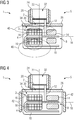
- FIG. 3 An improved with respect to the shielding effect of the antenna base plate 26 embodiment of the speaker module 1 is in Fig. 3 shown.
- the coil core 24 and thus the antenna coil 20 is positioned on the antenna base plate 26 in such a way that the coil axis 22 of the antenna coil 20 intersects the drive coil 16 of the loudspeaker 3.
- the coil axis 22 of the antenna coil 20 is aligned centrally to the drive coil 16 and also cuts the coil axis 18 of the drive coil 16 (in the middle of the drive coil 16). This results in a particularly favorable course of the magnetic field of the drive coil 16 (represented by schematically indicated magnetic field lines 40).
- FIG. 3 An improved with respect to the shielding effect of the antenna base plate 26 embodiment of the speaker module 1 is in Fig. 3 shown.
- the coil core 24 and thus the antenna coil 20 is positioned on the antenna base plate 26 in such a way that the coil axis 22 of the antenna coil 20 intersects the drive coil 16 of the loudspeaker 3.
- Upper magnetic field lines 40 (ie, the magnetic coil lines 40 closer to the antenna coil 20) are deflected by the antenna base plate 26 such that they are short-circuited approximately transversely (at right angles) to the coil axis 22 of the antenna coil 20. This results in particularly low interference from the magnetic field of the drive coil 16 to the antenna characteristic of the antenna unit 5.
- the coil core 24 with respect to the antenna base plate 26 at a small distance, for example by means of a film positioned. The magnetic field of the drive coil 16 is thereby additionally shielded from the antenna coil 20 with increased attenuation.
- the antenna unit 5 additionally comprises antenna side plates 42 which are arranged on the antenna coil 20 side facing away from the antenna base plate 26 angled to the latter and placed concretely on the outside of the housing 4.
- the antenna magnetic field generated by the antenna unit 20 is advantageously conducted around the loudspeaker 3 through these antenna side plates 42.
- the antenna side plates 42 also contribute to shielding the magnetic field of the drive coil 15 from the antenna coil 20.
- the antenna side plates 42 and the bobbin 24 are each spaced at a small distance from the antenna base plate 26.
- the corresponding distance is realized for example by an adhesive layer or by an interposed foil.
- the antenna side plates 42 and the bobbin 24, however, are in direct contact with the antenna base plate 26.
- the antenna side plates 42 are not placed on the housing 4, but form the respective perpendicular to the antenna base plate 26 side walls of the housing 4 itself.
- the antenna side plates 42 and the antenna base plate 26 are hereby made as an integral unit.
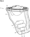
- the hearing device 2 shown represents a so-called in-the-ear hearing device (short IDO hearing aid).
- the hearing aid 2 comprises a hearing aid housing 50 which is adapted to the shape of the auditory canal of the hearing device wearer and faces away from the eardrum of the hearing aid wearer at its intended wearing position End is closed by a front panel (referred to as "face plate" 52).
- face plate a front panel
- the eardrum end facing the hearing aid housing 50 has a sound output 54.
- Housing inside is the speaker module 1 with the sound channel 32 forming bobbin 24 of the antenna unit 5 in this sound output 54 arranged.
- an electronics unit 56 which is circuitry coupled to the speaker module 1 and carries the elements for signal processing.
Landscapes
- Engineering & Computer Science (AREA)
- Physics & Mathematics (AREA)
- Signal Processing (AREA)
- Acoustics & Sound (AREA)
- General Health & Medical Sciences (AREA)
- Health & Medical Sciences (AREA)
- Neurosurgery (AREA)
- Otolaryngology (AREA)
- Computer Networks & Wireless Communication (AREA)
- Manufacturing & Machinery (AREA)
- Electromagnetism (AREA)
- Audible-Bandwidth Dynamoelectric Transducers Other Than Pickups (AREA)
- Headphones And Earphones (AREA)
- Details Of Audible-Bandwidth Transducers (AREA)
- Support Of Aerials (AREA)
- Circuit For Audible Band Transducer (AREA)
- Telephone Set Structure (AREA)
Claims (10)
- Module de haut-parleur (1) pour appareil auditif (2),- comportant un haut-parleur (3) muni d'une membrane de haut-parleur (7) et d'un dispositif d'entraînement (8) pour la membrane de haut-parleur (7),- comportant un boîtier (4) dans lequel est disposé le haut-parleur (3), et- comportant une unité d'antenne (5) qui comporte une bobine d'antenne (20) munie d'un axe de bobine (22), d'un noyau de bobine tubulaire (24) qui forme un canal acoustique (32), et d'une plaque de base d'antenne (26) dans laquelle est ménagée une ouverture de passage acoustique (30) débouchant dans le canal acoustique (32), dans lequel la bobine d'antenne (20), le noyau de bobine (24) et la plaque de base d'antenne (26) définissent une caractéristique d'antenne de l'unité d'antenne (5),caractérisé en ce que la paroi latérale du boîtier (4) est formée du côté de la membrane par la plaque de base d'antenne (26).
- Module de haut-parleur (1) selon la revendication 1,
dans lequel la membrane de haut-parleur (7) est fixée dans le boîtier (4) de manière à ce que le canal acoustique (32) soit ainsi par celle-ci de l'espace intérieur (34) du boîtier. - Module de haut-parleur (1) selon la revendication 1,
dans lequel la membrane de haut-parleur (7) est disposée dans le noyau de bobine tubulaire (24). - Module de haut-parleur (1) selon l'une des revendications 1 à 3,
dans lequel le dispositif d'entraînement (8) de la membrane de haut-parleur (7) comprend une bobine d'entraînement (16) comprenant un axe de bobine (18), et dans lequel l'axe de bobine (22) de la bobine d'antenne (20) est orienté perpendiculairement à l'axe de bobine (18) de la bobine d'entraînement (16). - Module de haut-parleur (1) selon l'une des revendications 1 à 4,
dans lequel le noyau de bobine (24) et la plaque de base d'antenne (26) sont réalisés en matériau ferromagnétique et/ou ferrimagnétique. - Module de haut-parleur (1) selon la revendication 4 ou 5,
dans lequel le noyau de bobine (24) est disposé de manière à ce que l'axe de bobine (22) de la bobine d'antenne (20) passe par la bobine d'entraînement (16) . - Module de haut-parleur (1) selon l'une des revendications 4 à 6,
dans lequel le noyau de bobine (24) est disposé de manière à ce que l'axe de bobine (22) de la bobine d'antenne (20) passe sensiblement au centre de la bobine d'entraînement (16). - Module de haut-parleur (1) selon l'une des revendications 1 à 7,
dans lequel l'unité d'antenne (5) comporte au moins une plaque latérale d'antenne (42) qui s'étend en formant un certain angle avec la plaque de base d'antenne (26) sur une face de la plaque de base d'antenne (26) qui est tournée à l'opposé de la bobine d'antenne (5). - Module de haut-parleur (1) selon la revendication 8,
dans lequel une autre paroi latérale du boîtier (4) est formée par la plaque latérale d'antenne (42). - Appareil auditif (2) comportant un module de haut-parleur (1) selon l'une quelconque des revendications 1 à 9.
Applications Claiming Priority (1)
| Application Number | Priority Date | Filing Date | Title |
|---|---|---|---|
| DE102016202658.5A DE102016202658A1 (de) | 2016-02-22 | 2016-02-22 | Lautsprechermodul für ein Hörgerät und Hörgerät |
Publications (2)
| Publication Number | Publication Date |
|---|---|
| EP3209032A1 EP3209032A1 (fr) | 2017-08-23 |
| EP3209032B1 true EP3209032B1 (fr) | 2019-08-21 |
Family
ID=57708532
Family Applications (1)
| Application Number | Title | Priority Date | Filing Date |
|---|---|---|---|
| EP17150204.0A Active EP3209032B1 (fr) | 2016-02-22 | 2017-01-03 | Module de haut-parleur pour un appareil auditif et appareil auditif |
Country Status (7)
| Country | Link |
|---|---|
| US (1) | US10097932B2 (fr) |
| EP (1) | EP3209032B1 (fr) |
| JP (1) | JP6379239B2 (fr) |
| CN (1) | CN107105373B (fr) |
| AU (1) | AU2017200327B2 (fr) |
| DE (1) | DE102016202658A1 (fr) |
| DK (1) | DK3209032T3 (fr) |
Families Citing this family (5)
| Publication number | Priority date | Publication date | Assignee | Title |
|---|---|---|---|---|
| DE102017219882B3 (de) * | 2017-11-08 | 2019-01-03 | Sivantos Pte. Ltd. | Hörgerät |
| EP3661231B1 (fr) | 2018-11-30 | 2023-06-28 | GN Hearing A/S | Dispositif auditif comportant une antenne |
| EP3736906A1 (fr) * | 2019-05-07 | 2020-11-11 | Oticon Medical A/S | Configuration d'antenne pour système d'aide auditive |
| US20230299459A1 (en) * | 2022-03-16 | 2023-09-21 | Honeywell International Inc. | Osprey migratory 7-band lte and ism antenna |
| DE102023202591A1 (de) | 2023-03-22 | 2024-09-26 | Sivantos Pte. Ltd. | Lautsprechersystem für eine im Ohr zu tragende Hörvorrichtung |
Family Cites Families (10)
| Publication number | Priority date | Publication date | Assignee | Title |
|---|---|---|---|---|
| US7190803B2 (en) * | 2002-04-09 | 2007-03-13 | Sonion Nederland Bv | Acoustic transducer having reduced thickness |
| DE10236940B3 (de) * | 2002-08-12 | 2004-02-19 | Siemens Audiologische Technik Gmbh | Platzsparende Antennenanordnung für Hörhilfegeräte |
| US7206425B2 (en) * | 2003-01-23 | 2007-04-17 | Adaptive Technologies, Inc. | Actuator for an active noise control system |
| DE102006043909B3 (de) * | 2006-09-19 | 2008-04-17 | Siemens Audiologische Technik Gmbh | Hörer mit zusätzlicher Abschirmeinrichtung und Hörgerät mit diesem Hörer |
| TW201106719A (en) * | 2009-08-12 | 2011-02-16 | Cotron Corp | Earphone |
| DK2826263T3 (da) * | 2012-03-16 | 2017-01-02 | Sonova Ag | Antenne til høreapparat, øreprop og høreapparat udstyret med denne antennetype / antenna for hearing device, ear tip and hearing device provided with such an antenna |
| CN203378015U (zh) * | 2012-12-13 | 2014-01-01 | 捷音特科技股份有限公司 | 双频同轴耳机 |
| DE102013210689B3 (de) | 2013-06-07 | 2014-10-02 | Siemens Medical Instruments Pte. Ltd. | Antenneneinrichtung für Hörinstrumente |
| US9668067B2 (en) * | 2013-07-22 | 2017-05-30 | Sonova Ag | Hearing device with improved low frequency response and method for manufacturing such a hearing device |
| DE102014200524A1 (de) * | 2014-01-14 | 2015-07-16 | Siemens Medical Instruments Pte. Ltd. | Antenneneinrichtung für Hörinstrumente |
-
2016
- 2016-02-22 DE DE102016202658.5A patent/DE102016202658A1/de not_active Withdrawn
-
2017
- 2017-01-03 DK DK17150204T patent/DK3209032T3/da active
- 2017-01-03 EP EP17150204.0A patent/EP3209032B1/fr active Active
- 2017-01-18 AU AU2017200327A patent/AU2017200327B2/en not_active Ceased
- 2017-02-08 US US15/427,187 patent/US10097932B2/en active Active
- 2017-02-16 CN CN201710083605.5A patent/CN107105373B/zh active Active
- 2017-02-21 JP JP2017029673A patent/JP6379239B2/ja active Active
Non-Patent Citations (1)
| Title |
|---|
| None * |
Also Published As
| Publication number | Publication date |
|---|---|
| AU2017200327A1 (en) | 2017-09-07 |
| JP2017153076A (ja) | 2017-08-31 |
| CN107105373B (zh) | 2020-01-07 |
| AU2017200327B2 (en) | 2018-04-26 |
| EP3209032A1 (fr) | 2017-08-23 |
| US10097932B2 (en) | 2018-10-09 |
| US20170245066A1 (en) | 2017-08-24 |
| DE102016202658A1 (de) | 2017-08-24 |
| DK3209032T3 (da) | 2019-11-25 |
| JP6379239B2 (ja) | 2018-08-22 |
| CN107105373A (zh) | 2017-08-29 |
Similar Documents
| Publication | Publication Date | Title |
|---|---|---|
| EP3209032B1 (fr) | Module de haut-parleur pour un appareil auditif et appareil auditif | |
| EP2894880B1 (fr) | Dispositif d'antenne pour appareils auditifs | |
| DE102013210689B3 (de) | Antenneneinrichtung für Hörinstrumente | |
| DE102013204681B4 (de) | Binaurales Hörinstrument sowie Ohrstück | |
| DE69233156T2 (de) | Verbessertes hörgerät | |
| DE102018221726A1 (de) | Audiovorrichtung mit akustischem Ventil | |
| EP3491846B1 (fr) | Prothese auditive et dispositif de prothese auditive | |
| EP1903835A2 (fr) | Appareil auditif avec dispositif de protection supplémentaire | |
| EP2200343A1 (fr) | Appareil de correction auditive portable dans l'oreille doté d'un microphone de guidage | |
| DE19620010B4 (de) | Lautsprechersystem mit Satellitengehäuse | |
| DE102010015400A1 (de) | Mikrofon für eine Hörvorrichtung sowie Verfahren zum Ermitteln eines Luftschalls und eines Körperschalls | |
| EP2375784B1 (fr) | Appareil auditif doté d'un blindage de haut-parleur amorphe | |
| EP3739906B1 (fr) | Instrument auditif | |
| EP4054208A1 (fr) | Appareil auditif, antenne pour un appareil auditif et procédé de fabrication d'un appareil auditif | |
| DE102006058318B4 (de) | Steuerverfahren für eine Hörvorrichtung mit Transpondererkennung | |
| DE102010012946B4 (de) | Hörgerät mit amorpher Lautsprecherabschirmung | |
| EP1273204A2 (fr) | Transducteur acoustique pour haut-parleur large bande ou ecouteur | |
| EP4380189A1 (fr) | Unité de transducteur acoustique | |
| EP4380187A1 (fr) | Unité de transducteur acoustique | |
| DE102023104024A1 (de) | Schallwandlereinheit | |
| EP3863304A1 (fr) | Appareil auditif avec antenne à couplage inductif | |
| WO2014049455A1 (fr) | Système auditif ainsi que procédé de transmission | |
| DE102009018884A1 (de) | Hörer für eine Hörvorrichtung mit flexibler Kontakteinrichtung | |
| EP1052830A2 (fr) | Terminal radiotéléphonique mobile | |
| DE102009008618A1 (de) | Hörvorrichtung mit zwei elektrischen Einheiten, die über Drähte mit einander verbunden sind. |
Legal Events
| Date | Code | Title | Description |
|---|---|---|---|
| PUAI | Public reference made under article 153(3) epc to a published international application that has entered the european phase |
Free format text: ORIGINAL CODE: 0009012 |
|
| STAA | Information on the status of an ep patent application or granted ep patent |
Free format text: STATUS: THE APPLICATION HAS BEEN PUBLISHED |
|
| AK | Designated contracting states |
Kind code of ref document: A1 Designated state(s): AL AT BE BG CH CY CZ DE DK EE ES FI FR GB GR HR HU IE IS IT LI LT LU LV MC MK MT NL NO PL PT RO RS SE SI SK SM TR |
|
| AX | Request for extension of the european patent |
Extension state: BA ME |
|
| RAP1 | Party data changed (applicant data changed or rights of an application transferred) |
Owner name: SIVANTOS PTE. LTD. |
|
| STAA | Information on the status of an ep patent application or granted ep patent |
Free format text: STATUS: REQUEST FOR EXAMINATION WAS MADE |
|
| 17P | Request for examination filed |
Effective date: 20180223 |
|
| RBV | Designated contracting states (corrected) |
Designated state(s): AL AT BE BG CH CY CZ DE DK EE ES FI FR GB GR HR HU IE IS IT LI LT LU LV MC MK MT NL NO PL PT RO RS SE SI SK SM TR |
|
| RIC1 | Information provided on ipc code assigned before grant |
Ipc: H04R 25/00 20060101AFI20190102BHEP |
|
| GRAP | Despatch of communication of intention to grant a patent |
Free format text: ORIGINAL CODE: EPIDOSNIGR1 |
|
| STAA | Information on the status of an ep patent application or granted ep patent |
Free format text: STATUS: GRANT OF PATENT IS INTENDED |
|
| INTG | Intention to grant announced |
Effective date: 20190320 |
|
| GRAS | Grant fee paid |
Free format text: ORIGINAL CODE: EPIDOSNIGR3 |
|
| GRAA | (expected) grant |
Free format text: ORIGINAL CODE: 0009210 |
|
| STAA | Information on the status of an ep patent application or granted ep patent |
Free format text: STATUS: THE PATENT HAS BEEN GRANTED |
|
| AK | Designated contracting states |
Kind code of ref document: B1 Designated state(s): AL AT BE BG CH CY CZ DE DK EE ES FI FR GB GR HR HU IE IS IT LI LT LU LV MC MK MT NL NO PL PT RO RS SE SI SK SM TR |
|
| REG | Reference to a national code |
Ref country code: GB Ref legal event code: FG4D Free format text: NOT ENGLISH |
|
| REG | Reference to a national code |
Ref country code: CH Ref legal event code: EP |
|
| REG | Reference to a national code |
Ref country code: DE Ref legal event code: R096 Ref document number: 502017002053 Country of ref document: DE |
|
| REG | Reference to a national code |
Ref country code: CH Ref legal event code: NV Representative=s name: E. BLUM AND CO. AG PATENT- UND MARKENANWAELTE , CH |
|
| REG | Reference to a national code |
Ref country code: AT Ref legal event code: REF Ref document number: 1171109 Country of ref document: AT Kind code of ref document: T Effective date: 20190915 |
|
| REG | Reference to a national code |
Ref country code: IE Ref legal event code: FG4D Free format text: LANGUAGE OF EP DOCUMENT: GERMAN |
|
| REG | Reference to a national code |
Ref country code: DK Ref legal event code: T3 Effective date: 20191119 |
|
| REG | Reference to a national code |
Ref country code: LT Ref legal event code: MG4D |
|
| REG | Reference to a national code |
Ref country code: NL Ref legal event code: MP Effective date: 20190821 |
|
| PG25 | Lapsed in a contracting state [announced via postgrant information from national office to epo] |
Ref country code: PT Free format text: LAPSE BECAUSE OF FAILURE TO SUBMIT A TRANSLATION OF THE DESCRIPTION OR TO PAY THE FEE WITHIN THE PRESCRIBED TIME-LIMIT Effective date: 20191223 Ref country code: FI Free format text: LAPSE BECAUSE OF FAILURE TO SUBMIT A TRANSLATION OF THE DESCRIPTION OR TO PAY THE FEE WITHIN THE PRESCRIBED TIME-LIMIT Effective date: 20190821 Ref country code: SE Free format text: LAPSE BECAUSE OF FAILURE TO SUBMIT A TRANSLATION OF THE DESCRIPTION OR TO PAY THE FEE WITHIN THE PRESCRIBED TIME-LIMIT Effective date: 20190821 Ref country code: HR Free format text: LAPSE BECAUSE OF FAILURE TO SUBMIT A TRANSLATION OF THE DESCRIPTION OR TO PAY THE FEE WITHIN THE PRESCRIBED TIME-LIMIT Effective date: 20190821 Ref country code: LT Free format text: LAPSE BECAUSE OF FAILURE TO SUBMIT A TRANSLATION OF THE DESCRIPTION OR TO PAY THE FEE WITHIN THE PRESCRIBED TIME-LIMIT Effective date: 20190821 Ref country code: NO Free format text: LAPSE BECAUSE OF FAILURE TO SUBMIT A TRANSLATION OF THE DESCRIPTION OR TO PAY THE FEE WITHIN THE PRESCRIBED TIME-LIMIT Effective date: 20191121 Ref country code: NL Free format text: LAPSE BECAUSE OF FAILURE TO SUBMIT A TRANSLATION OF THE DESCRIPTION OR TO PAY THE FEE WITHIN THE PRESCRIBED TIME-LIMIT Effective date: 20190821 Ref country code: BG Free format text: LAPSE BECAUSE OF FAILURE TO SUBMIT A TRANSLATION OF THE DESCRIPTION OR TO PAY THE FEE WITHIN THE PRESCRIBED TIME-LIMIT Effective date: 20191121 |
|
| PG25 | Lapsed in a contracting state [announced via postgrant information from national office to epo] |
Ref country code: AL Free format text: LAPSE BECAUSE OF FAILURE TO SUBMIT A TRANSLATION OF THE DESCRIPTION OR TO PAY THE FEE WITHIN THE PRESCRIBED TIME-LIMIT Effective date: 20190821 Ref country code: LV Free format text: LAPSE BECAUSE OF FAILURE TO SUBMIT A TRANSLATION OF THE DESCRIPTION OR TO PAY THE FEE WITHIN THE PRESCRIBED TIME-LIMIT Effective date: 20190821 Ref country code: IS Free format text: LAPSE BECAUSE OF FAILURE TO SUBMIT A TRANSLATION OF THE DESCRIPTION OR TO PAY THE FEE WITHIN THE PRESCRIBED TIME-LIMIT Effective date: 20191221 Ref country code: RS Free format text: LAPSE BECAUSE OF FAILURE TO SUBMIT A TRANSLATION OF THE DESCRIPTION OR TO PAY THE FEE WITHIN THE PRESCRIBED TIME-LIMIT Effective date: 20190821 Ref country code: GR Free format text: LAPSE BECAUSE OF FAILURE TO SUBMIT A TRANSLATION OF THE DESCRIPTION OR TO PAY THE FEE WITHIN THE PRESCRIBED TIME-LIMIT Effective date: 20191122 |
|
| PG25 | Lapsed in a contracting state [announced via postgrant information from national office to epo] |
Ref country code: TR Free format text: LAPSE BECAUSE OF FAILURE TO SUBMIT A TRANSLATION OF THE DESCRIPTION OR TO PAY THE FEE WITHIN THE PRESCRIBED TIME-LIMIT Effective date: 20190821 |
|
| PG25 | Lapsed in a contracting state [announced via postgrant information from national office to epo] |
Ref country code: IT Free format text: LAPSE BECAUSE OF FAILURE TO SUBMIT A TRANSLATION OF THE DESCRIPTION OR TO PAY THE FEE WITHIN THE PRESCRIBED TIME-LIMIT Effective date: 20190821 Ref country code: RO Free format text: LAPSE BECAUSE OF FAILURE TO SUBMIT A TRANSLATION OF THE DESCRIPTION OR TO PAY THE FEE WITHIN THE PRESCRIBED TIME-LIMIT Effective date: 20190821 Ref country code: PL Free format text: LAPSE BECAUSE OF FAILURE TO SUBMIT A TRANSLATION OF THE DESCRIPTION OR TO PAY THE FEE WITHIN THE PRESCRIBED TIME-LIMIT Effective date: 20190821 Ref country code: EE Free format text: LAPSE BECAUSE OF FAILURE TO SUBMIT A TRANSLATION OF THE DESCRIPTION OR TO PAY THE FEE WITHIN THE PRESCRIBED TIME-LIMIT Effective date: 20190821 |
|
| PG25 | Lapsed in a contracting state [announced via postgrant information from national office to epo] |
Ref country code: CZ Free format text: LAPSE BECAUSE OF FAILURE TO SUBMIT A TRANSLATION OF THE DESCRIPTION OR TO PAY THE FEE WITHIN THE PRESCRIBED TIME-LIMIT Effective date: 20190821 Ref country code: SM Free format text: LAPSE BECAUSE OF FAILURE TO SUBMIT A TRANSLATION OF THE DESCRIPTION OR TO PAY THE FEE WITHIN THE PRESCRIBED TIME-LIMIT Effective date: 20190821 Ref country code: SK Free format text: LAPSE BECAUSE OF FAILURE TO SUBMIT A TRANSLATION OF THE DESCRIPTION OR TO PAY THE FEE WITHIN THE PRESCRIBED TIME-LIMIT Effective date: 20190821 Ref country code: IS Free format text: LAPSE BECAUSE OF FAILURE TO SUBMIT A TRANSLATION OF THE DESCRIPTION OR TO PAY THE FEE WITHIN THE PRESCRIBED TIME-LIMIT Effective date: 20200224 |
|
| REG | Reference to a national code |
Ref country code: DE Ref legal event code: R097 Ref document number: 502017002053 Country of ref document: DE |
|
| PLBE | No opposition filed within time limit |
Free format text: ORIGINAL CODE: 0009261 |
|
| STAA | Information on the status of an ep patent application or granted ep patent |
Free format text: STATUS: NO OPPOSITION FILED WITHIN TIME LIMIT |
|
| PG2D | Information on lapse in contracting state deleted |
Ref country code: IS |
|
| 26N | No opposition filed |
Effective date: 20200603 |
|
| PG25 | Lapsed in a contracting state [announced via postgrant information from national office to epo] |
Ref country code: MC Free format text: LAPSE BECAUSE OF FAILURE TO SUBMIT A TRANSLATION OF THE DESCRIPTION OR TO PAY THE FEE WITHIN THE PRESCRIBED TIME-LIMIT Effective date: 20190821 Ref country code: SI Free format text: LAPSE BECAUSE OF FAILURE TO SUBMIT A TRANSLATION OF THE DESCRIPTION OR TO PAY THE FEE WITHIN THE PRESCRIBED TIME-LIMIT Effective date: 20190821 |
|
| REG | Reference to a national code |
Ref country code: BE Ref legal event code: MM Effective date: 20200131 |
|
| PG25 | Lapsed in a contracting state [announced via postgrant information from national office to epo] |
Ref country code: LU Free format text: LAPSE BECAUSE OF NON-PAYMENT OF DUE FEES Effective date: 20200103 Ref country code: ES Free format text: LAPSE BECAUSE OF FAILURE TO SUBMIT A TRANSLATION OF THE DESCRIPTION OR TO PAY THE FEE WITHIN THE PRESCRIBED TIME-LIMIT Effective date: 20190821 |
|
| PG25 | Lapsed in a contracting state [announced via postgrant information from national office to epo] |
Ref country code: BE Free format text: LAPSE BECAUSE OF NON-PAYMENT OF DUE FEES Effective date: 20200131 |
|
| PG25 | Lapsed in a contracting state [announced via postgrant information from national office to epo] |
Ref country code: IE Free format text: LAPSE BECAUSE OF NON-PAYMENT OF DUE FEES Effective date: 20200103 |
|
| PG25 | Lapsed in a contracting state [announced via postgrant information from national office to epo] |
Ref country code: MT Free format text: LAPSE BECAUSE OF FAILURE TO SUBMIT A TRANSLATION OF THE DESCRIPTION OR TO PAY THE FEE WITHIN THE PRESCRIBED TIME-LIMIT Effective date: 20190821 Ref country code: CY Free format text: LAPSE BECAUSE OF FAILURE TO SUBMIT A TRANSLATION OF THE DESCRIPTION OR TO PAY THE FEE WITHIN THE PRESCRIBED TIME-LIMIT Effective date: 20190821 |
|
| PG25 | Lapsed in a contracting state [announced via postgrant information from national office to epo] |
Ref country code: MK Free format text: LAPSE BECAUSE OF FAILURE TO SUBMIT A TRANSLATION OF THE DESCRIPTION OR TO PAY THE FEE WITHIN THE PRESCRIBED TIME-LIMIT Effective date: 20190821 |
|
| REG | Reference to a national code |
Ref country code: AT Ref legal event code: MM01 Ref document number: 1171109 Country of ref document: AT Kind code of ref document: T Effective date: 20220103 |
|
| PG25 | Lapsed in a contracting state [announced via postgrant information from national office to epo] |
Ref country code: AT Free format text: LAPSE BECAUSE OF NON-PAYMENT OF DUE FEES Effective date: 20220103 |
|
| PGFP | Annual fee paid to national office [announced via postgrant information from national office to epo] |
Ref country code: DE Payment date: 20240119 Year of fee payment: 8 Ref country code: GB Payment date: 20240124 Year of fee payment: 8 Ref country code: CH Payment date: 20240202 Year of fee payment: 8 |
|
| PGFP | Annual fee paid to national office [announced via postgrant information from national office to epo] |
Ref country code: FR Payment date: 20240123 Year of fee payment: 8 Ref country code: DK Payment date: 20240123 Year of fee payment: 8 |