EP3209032B1 - Loudspeaker module for a hearing aid and hearing aid - Google Patents
Loudspeaker module for a hearing aid and hearing aid Download PDFInfo
- Publication number
- EP3209032B1 EP3209032B1 EP17150204.0A EP17150204A EP3209032B1 EP 3209032 B1 EP3209032 B1 EP 3209032B1 EP 17150204 A EP17150204 A EP 17150204A EP 3209032 B1 EP3209032 B1 EP 3209032B1
- Authority
- EP
- European Patent Office
- Prior art keywords
- antenna
- coil
- loudspeaker
- housing
- hearing aid
- Prior art date
- Legal status (The legal status is an assumption and is not a legal conclusion. Google has not performed a legal analysis and makes no representation as to the accuracy of the status listed.)
- Active
Links
Images


Classifications
-
- H—ELECTRICITY
- H04—ELECTRIC COMMUNICATION TECHNIQUE
- H04R—LOUDSPEAKERS, MICROPHONES, GRAMOPHONE PICK-UPS OR LIKE ACOUSTIC ELECTROMECHANICAL TRANSDUCERS; DEAF-AID SETS; PUBLIC ADDRESS SYSTEMS
- H04R25/00—Deaf-aid sets, i.e. electro-acoustic or electro-mechanical hearing aids; Electric tinnitus maskers providing an auditory perception
- H04R25/60—Mounting or interconnection of hearing aid parts, e.g. inside tips, housings or to ossicles
-
- H—ELECTRICITY
- H04—ELECTRIC COMMUNICATION TECHNIQUE
- H04R—LOUDSPEAKERS, MICROPHONES, GRAMOPHONE PICK-UPS OR LIKE ACOUSTIC ELECTROMECHANICAL TRANSDUCERS; DEAF-AID SETS; PUBLIC ADDRESS SYSTEMS
- H04R9/00—Transducers of moving-coil, moving-strip, or moving-wire type
- H04R9/06—Loudspeakers
-
- H—ELECTRICITY
- H01—ELECTRIC ELEMENTS
- H01Q—ANTENNAS, i.e. RADIO AERIALS
- H01Q1/00—Details of, or arrangements associated with, antennas
- H01Q1/12—Supports; Mounting means
- H01Q1/22—Supports; Mounting means by structural association with other equipment or articles
- H01Q1/24—Supports; Mounting means by structural association with other equipment or articles with receiving set
-
- H—ELECTRICITY
- H01—ELECTRIC ELEMENTS
- H01Q—ANTENNAS, i.e. RADIO AERIALS
- H01Q1/00—Details of, or arrangements associated with, antennas
- H01Q1/27—Adaptation for use in or on movable bodies
- H01Q1/273—Adaptation for carrying or wearing by persons or animals
-
- H—ELECTRICITY
- H01—ELECTRIC ELEMENTS
- H01Q—ANTENNAS, i.e. RADIO AERIALS
- H01Q1/00—Details of, or arrangements associated with, antennas
- H01Q1/44—Details of, or arrangements associated with, antennas using equipment having another main function to serve additionally as an antenna, e.g. means for giving an antenna an aesthetic aspect
-
- H—ELECTRICITY
- H01—ELECTRIC ELEMENTS
- H01Q—ANTENNAS, i.e. RADIO AERIALS
- H01Q7/00—Loop antennas with a substantially uniform current distribution around the loop and having a directional radiation pattern in a plane perpendicular to the plane of the loop
- H01Q7/06—Loop antennas with a substantially uniform current distribution around the loop and having a directional radiation pattern in a plane perpendicular to the plane of the loop with core of ferromagnetic material
- H01Q7/08—Ferrite rod or like elongated core
-
- H—ELECTRICITY
- H04—ELECTRIC COMMUNICATION TECHNIQUE
- H04R—LOUDSPEAKERS, MICROPHONES, GRAMOPHONE PICK-UPS OR LIKE ACOUSTIC ELECTROMECHANICAL TRANSDUCERS; DEAF-AID SETS; PUBLIC ADDRESS SYSTEMS
- H04R1/00—Details of transducers, loudspeakers or microphones
- H04R1/10—Earpieces; Attachments therefor ; Earphones; Monophonic headphones
- H04R1/1058—Manufacture or assembly
- H04R1/1075—Mountings of transducers in earphones or headphones
-
- H—ELECTRICITY
- H04—ELECTRIC COMMUNICATION TECHNIQUE
- H04R—LOUDSPEAKERS, MICROPHONES, GRAMOPHONE PICK-UPS OR LIKE ACOUSTIC ELECTROMECHANICAL TRANSDUCERS; DEAF-AID SETS; PUBLIC ADDRESS SYSTEMS
- H04R11/00—Transducers of moving-armature or moving-core type
- H04R11/02—Loudspeakers
-
- H—ELECTRICITY
- H04—ELECTRIC COMMUNICATION TECHNIQUE
- H04R—LOUDSPEAKERS, MICROPHONES, GRAMOPHONE PICK-UPS OR LIKE ACOUSTIC ELECTROMECHANICAL TRANSDUCERS; DEAF-AID SETS; PUBLIC ADDRESS SYSTEMS
- H04R25/00—Deaf-aid sets, i.e. electro-acoustic or electro-mechanical hearing aids; Electric tinnitus maskers providing an auditory perception
- H04R25/55—Deaf-aid sets, i.e. electro-acoustic or electro-mechanical hearing aids; Electric tinnitus maskers providing an auditory perception using an external connection, either wireless or wired
- H04R25/554—Deaf-aid sets, i.e. electro-acoustic or electro-mechanical hearing aids; Electric tinnitus maskers providing an auditory perception using an external connection, either wireless or wired using a wireless connection, e.g. between microphone and amplifier or using Tcoils
-
- H—ELECTRICITY
- H04—ELECTRIC COMMUNICATION TECHNIQUE
- H04R—LOUDSPEAKERS, MICROPHONES, GRAMOPHONE PICK-UPS OR LIKE ACOUSTIC ELECTROMECHANICAL TRANSDUCERS; DEAF-AID SETS; PUBLIC ADDRESS SYSTEMS
- H04R25/00—Deaf-aid sets, i.e. electro-acoustic or electro-mechanical hearing aids; Electric tinnitus maskers providing an auditory perception
- H04R25/65—Housing parts, e.g. shells, tips or moulds, or their manufacture
-
- H—ELECTRICITY
- H04—ELECTRIC COMMUNICATION TECHNIQUE
- H04R—LOUDSPEAKERS, MICROPHONES, GRAMOPHONE PICK-UPS OR LIKE ACOUSTIC ELECTROMECHANICAL TRANSDUCERS; DEAF-AID SETS; PUBLIC ADDRESS SYSTEMS
- H04R9/00—Transducers of moving-coil, moving-strip, or moving-wire type
- H04R9/02—Details
-
- H—ELECTRICITY
- H04—ELECTRIC COMMUNICATION TECHNIQUE
- H04R—LOUDSPEAKERS, MICROPHONES, GRAMOPHONE PICK-UPS OR LIKE ACOUSTIC ELECTROMECHANICAL TRANSDUCERS; DEAF-AID SETS; PUBLIC ADDRESS SYSTEMS
- H04R2225/00—Details of deaf aids covered by H04R25/00, not provided for in any of its subgroups
- H04R2225/025—In the ear hearing aids [ITE] hearing aids
-
- H—ELECTRICITY
- H04—ELECTRIC COMMUNICATION TECHNIQUE
- H04R—LOUDSPEAKERS, MICROPHONES, GRAMOPHONE PICK-UPS OR LIKE ACOUSTIC ELECTROMECHANICAL TRANSDUCERS; DEAF-AID SETS; PUBLIC ADDRESS SYSTEMS
- H04R2225/00—Details of deaf aids covered by H04R25/00, not provided for in any of its subgroups
- H04R2225/51—Aspects of antennas or their circuitry in or for hearing aids
-
- H—ELECTRICITY
- H04—ELECTRIC COMMUNICATION TECHNIQUE
- H04R—LOUDSPEAKERS, MICROPHONES, GRAMOPHONE PICK-UPS OR LIKE ACOUSTIC ELECTROMECHANICAL TRANSDUCERS; DEAF-AID SETS; PUBLIC ADDRESS SYSTEMS
- H04R2400/00—Loudspeakers
- H04R2400/11—Aspects regarding the frame of loudspeaker transducers
Definitions
- the invention relates to a loudspeaker module for a hearing aid. Furthermore, the invention relates to a hearing aid with such a loudspeaker module.
- hearing aid includes in particular hearing aid devices that serve people with a hearing loss to compensate for this hearing loss at least partially.
- hearing aid devices usually comprise as components at least one microphone for recording acoustic sound signals (eg voices, music and / or other environmental noises), a signal processing unit (also referred to as signal processor) for filtering and at least partially amplifying the recorded sound signals and a (usually also as “ Handset "speakers) for outputting the processed sound signals to an ear of a hearing aid wearer (ie the person with hearing loss).
- hearing aid devices include, for example, a bone conduction or cochlear implant, depending on the type of hearing loss, for the mechanical or electrical stimulation of the hearing center of the hearing device wearer.
- hearing aid also includes other devices that are used to output (acoustic) sound signals to the hearing of the corresponding hearing aid wearer. Such devices are, for example, so-called tinnitus maskers, headphones, headsets and the like.
- a hearing aid in particular a hearing aid, can be designed, for example, as a single, "monaural" hearing aid for the independent supply of an ear of the hearing aid wearer.
- a monaural hearing aid or hearing aid device usually all components described above are integrated.
- the hearing aid or hearing aid can also be part of a binaural hearing aid system his.
- Such a binaural hearing device system is regularly set up to supply both ears of the hearing device wearer.
- a data exchange takes place, which allows the actual binaural signal processing.
- binaural hearing aids are often equipped with signal processing algorithms, by means of which, for example, to generate a directional effect, the sound signals received by both hearing aids are taken into account. For this purpose, the sound signals must be transmitted between the hearing aids recognized.
- both binaural hearing aids have at least one antenna for transmitting and / or receiving the data to be exchanged.
- These antennas constitute an additional component to the components described above, which, as is known, must be placed within a hearing aid housing (at least within the installation space available for the hearing aid). In order to maintain a sufficiently high quality with regard to the transmission and reception of the data to be exchanged, however, a certain size (in particular a certain volume) of the antenna can not be exceeded.
- the sound quality is one of the main quality features that the hearing aid wearer perceives when using a hearing aid.
- the sound characteristics and the efficiency in low frequencies (and thus the subjectively perceived Sound quality) of a loudspeaker is characterized in particular by a back volume (also referred to as “back volume”), which is usually formed by a volume which is delimited by a sound signal generating loudspeaker membrane from the environment, and by a front volume (also referred to as "front volume”), which is arranged between the loudspeaker diaphragm and the sound outlet of the listener or between the sound outlet of the listener and the eardrum.
- back volume also referred to as "back volume”
- front volume also referred to as "front volume”
- the ratio of back volume and front volume has an effect on the quality of complaint and the efficiency of the listener.
- the term of the front volume refers to the volume between the loudspeaker diaphragm and the sound outlet of the listener.
- Conventional loudspeakers used in a hearing device are usually arranged inside the hearing device housing and are connected to a sound output of the hearing device housing by means of a sound socket or a sound tube which forms a sound channel.
- the volume arranged between the loudspeaker diaphragm and the sound outlet therefore consequently represents the front volume in this sense.
- the object of the invention is to enable an improved sound characteristic in a hearing device equipped for radio-based data transmission.
- the loudspeaker module is set up and provided for use in a hearing device with radio-based data transmission.
- the loudspeaker module in this case comprises a loudspeaker comprising a loudspeaker diaphragm and a drive for this loudspeaker diaphragm (in the following: diaphragm drive).
- the speaker module comprises a housing in which the speaker is arranged.
- the housing preferably encloses the loudspeaker on all sides except for an opening through which acoustic signals can escape into the environment during operation of the loudspeaker.
- the speaker module also includes an antenna unit for transmitting and / or receiving electromagnetic signals.
- This antenna unit has an antenna coil with a coil axis and a tubular coil core on which the antenna coil is wound and which forms a sound channel on.
- tubular is to be understood without any limitation to a specific cross-sectional shape of the tube.
- the tubular extending coil core in particular a square, rectangular, polygonal, oval or round cross-section.
- the cross-sectional shape varies along the spool core.
- the antenna coil preferably extends in a straight line along its coil axis.
- the antenna unit has an antenna base plate, in which a sound passage opening opening into the sound channel of the coil core is formed.
- the antenna coil, the coil core and the antenna base plate specify an antenna characteristic of the antenna unit.
- the side wall of the housing on the membrane side - ie the speaker membrane (surface) opposite side wall - is formed by the antenna base plate.
- the speaker module is a unit formed of the speaker and the antenna unit, in which the antenna unit is integrated with the case of the speaker.
- a sound exit opening of the loudspeaker module by means of which the sound generated by the loudspeaker membrane can be emitted into the environment, is preferably formed by the free end of the sound channel facing away from the antenna base plate (ie arranged at the free end of the coil core).
- no additional housing parts are interposed between the loudspeaker and the antenna unit, specifically the antenna base plate.
- antenna characteristics is meant here and below in particular features of the antenna unit, such as e.g. a (as low as possible, electrical) transmission power for data transmission to a receiver, a high reception power and a low susceptibility to interference.
- the sound channel is formed by the coil core wound with the antenna coil, it is possible to save space required for a separate antenna and thus the installation space remaining in the hearing aid housing without affecting the volume of the speaker, especially on the back volume, reduced or alternatively a speaker with a correspondingly increased back volume are installed.
- the antenna base plate forms a side wall of the loudspeaker housing, the front volume, which is largely formed by the sound channel, can advantageously be reduced in relation to the back volume while maintaining the same antenna volume, in particular with the coil core remaining the same length.
- the antenna unit moves closer to the speaker membrane. This advantageously reduces the acoustic resistance for the loudspeaker diaphragm and consequently improves the sound characteristic of the loudspeaker.
- the invention is based on the own knowledge that a reduction of the front volume and an increase of the back volume increases the bandwidth and the efficiency of the speaker in low frequencies.
- the loudspeaker can have a higher (sound output) performance with a constant or even reduced size (and in particular with constant electrical power).
- the integration of the antenna baseplate into the housing of the loudspeaker module results in an overall shortest possible length of the loudspeaker module (in particular along the coil axis of the antenna coil), which is advantageous in terms of a compact design of the entire hearing device.
- the loudspeaker diaphragm is fastened in the housing in such a way that the sound channel is thereby separated from the interior of the housing. This means that the housing interior forms the back volume.
- the loudspeaker diaphragm seals the sound channel with respect to the interior of the housing.
- the loudspeaker diaphragm is moved directly to the antenna base plate except for a necessary oscillation distance.
- the loudspeaker diaphragm is fastened to the side walls of the housing, for example via a particularly metallic edge region, or it is mounted directly on the antenna baseplate.
- the volume of the loudspeaker from the environment here specifically the sound channel, separated back volume, especially in relation to the front volume, increases.
- the front volume is reduced to the volume already present in the spool core.
- An increased back volume also reduces the acoustic resistance for the speaker diaphragm when generating the acoustic (output) signals.
- the bass characteristics of the loudspeaker are improved by an increased back volume.
- the loudspeaker diaphragm is arranged in the coil core (that is to say inside the coil core).
- the speaker diaphragm is arranged radially to the coil axis of the antenna coil.
- the back volume is further increased and the sound channel delimited by the loudspeaker diaphragm from the interior of the housing, and thus the front volume arranged in the sound channel, are correspondingly further reduced, so that the sound characteristic of the loudspeaker is further improved.
- both high and low frequencies can be presented better (preferably with a clear sound).
- the membrane drive comprises a drive coil with a coil axis.
- the drive coil along its coil axis is in particular straight elongated, that is, the drive coil has in comparison to their extent transverse to the coil axis (also referred to as "thickness") a greater length.
- the coil axis of the antenna coil is preferably aligned perpendicular to the coil axis of the drive coil in this embodiment.
- the antenna base plate is expediently arranged perpendicular to the coil axis of the antenna coil.
- a coupling of the magnetic field generated by this coil in the corresponding other coil is advantageously reduced during operation of the respective coil.
- this can be a disturbing induction of currents through the magnetic field of a coil in the other Coil advantageously be reduced.
- especially a disturbance of the antenna is reduced by the magnetic field of the drive coil and thus increases the quality of the data transmission of the antenna unit.
- the respective coil axes of the antenna coil and the drive coil are perpendicular to each other. In other words, the two coil axes intersect at an angle of 90 °.
- the coil core and the antenna base plate are formed from ferromagnetic and / or ferrimagnetic material.
- the coil core and the antenna base plate are formed from ferrite. Due to the magnetic properties present thereby, both the coil core and the antenna base plate thus contribute particularly advantageously to the antenna characteristic of the antenna unit.
- the antenna unit is preferably a magnetic antenna, in particular a "ferrite antenna". Such antennas are advantageously particularly well suited for signal transmission in a frequency range between preferably about 100 kHz to 10 MHz.
- these antennas enable data transmission over relatively short distances, such as the order of magnitude of the distance between the two ears of a human being to each other, while at the same time (in particular compared to high-frequency data transmission systems) low electrical power consumption.
- the magnetic fields used for data transmission in these antennas are advantageously not or only to a negligible extent dampened by the body tissue (in particular the head) arranged between the transmitting and the receiving antenna in this comparatively low frequency range.
- the magnetic antenna advantageously also has a smaller size compared to an antenna for an electric field, which in turn contributes to the saving of installation space.
- the antenna base plate advantageously acts as a kind of magnetic shield between the drive coil and the antenna coil.
- the antenna baseplate closes due to its to the coil axis of the Drive coil parallel arrangement - and thus their vertical orientation to the antenna coil - the magnetic field of the drive coil at least transversely to the coil axis of the antenna coil at least largely so that a coupling of the magnetic field of the drive coil and thereby induced currents in the antenna coil are negligible.
- the quality of the data transmission of the antenna unit (in particular their robustness against interfering magnetic fields) is further increased.
- the coil core of the antenna unit is arranged in particular such that the coil axis of the antenna coil intersects the drive coil.
- the coil core is preferably arranged such that the coil axis of the antenna coil essentially - i. exactly or approximately, in particular with respect to the length of the drive coil by a multiple smaller distance - runs centrally to the drive coil.
- an arrangement of the respective magnetic fields of the drive coil and the antenna coil which is also referred to as "magnetically symmetrical" is advantageously achieved, in particular in combination with the ferromagnetic and / or ferrimagnetic antenna base plate, a particularly high shielding effect or a negligible coupling of the magnetic field of the drive coil is made possible in the antenna coil.
- the antenna unit comprises at least one antenna side plate, which extends at an angle away from the antenna coil side of the antenna base plate angled to the antenna base plate, preferably perpendicular to this.
- the respective antenna side plate expediently covers a side wall of the housing (further to the above-described membrane-side side wall).
- the respective antenna side plate or plates are preferably formed of the same material as the coil core and the antenna base plate.
- the antenna side plate leads advantageously to an extension of the antenna unit (in particular along the coil axis of the antenna coil) and thus to a further improvement of the antenna characteristic.
- the magnetic field generated by the antenna coil is guided around the speaker due to the arrangement of the respective antenna side plate.
- the respective antenna side plate also contributes to the screening effect of the antenna base plate and thus to the shielding of the magnetic field generated by the drive coil relative to the antenna coil.
- At least one of the further side walls of the housing described above is formed by the or each antenna side plate. This means that this side wall of the housing is eliminated and replaced by the antenna side plate.
- the antenna unit in particular comprises four of the antenna side plates described above, these form in the case of the present development, a box-like or cup-like part of the housing.
- the antenna base plate is connected at a distance, for example in the range of 50 to 150 .mu.m, in particular of about 100 .mu.m, to the spool core and / or optionally to the or the respective antenna side plate.
- the antenna base plate, the coil core and optionally the respective antenna side plate or plates are not directly in contact with each other, but are spaced apart from one another and held to one another, for example by means of an adhesive layer and / or different insulating spacers - for example plastic. This advantageously results in a high signal-to-noise ratio of the antenna unit, i. H. achieved a particularly trouble-free reception.
- the magnetic field of the drive coil of the speaker is shielded from the antenna with better damping.
- the loudspeaker is a so-called “balanced armature” loudspeaker or a "moving" loudspeaker
- the loudspeaker in particular its diaphragm drive, comprises in addition to the drive coil two permanent magnets and an armature which is arranged in a gap between the two permanent magnets and which is coupled to the loudspeaker diaphragm via a "drive rod" Anchor also passes through the drive coil.
- the hearing aid according to the invention comprises a loudspeaker module of the type described above, and preferably a (hearing aid) housing in which the loudspeaker module is arranged.
- the loudspeaker module is preferably positioned with its sound channel in a sound exit opening of the hearing device housing.
- Fig. 1 is a speaker module 1 for a (exemplary in Fig. 6 shown) hearing aid 2 shown.
- the speaker module 1 comprises a speaker 3, which is arranged in a housing 4.
- the speaker module 1 comprises an antenna unit 5, which is formed as part of the housing 4.
- the loudspeaker module 1 thus forms an integrated structural unit for the hearing device 2, which serves for the output of acoustic signals as well as for the transmission and / or reception of electromagnetic (data) signals.
- the speaker 3 is formed in the illustrated embodiment as a so-called "balanced-armature” loudspeaker.
- the loudspeaker 3 in this case comprises a loudspeaker diaphragm 7, which is set in vibration during operation of the loudspeaker 3 and thereby generates the acoustic signals.
- the loudspeaker 3 comprises a (membrane) drive 8.
- This diaphragm drive 8 has a substantially U-shaped armature 10 (also referred to as "armature”) which is connected to the loudspeaker diaphragm 7 by means of a drive rod 12 is coupled.
- the membrane drive 8 further has two permanent magnets 14, which are arranged at a distance from one another and between which a leg of the armature 10 extends.
- the membrane drive 8 comprises a drive coil 16, by means of which a magnetic field for alternating magnetization of the armature 10 is generated during operation of the loudspeaker 3.
- the drive coil 16 is elongated along a coil axis 18, i. with a larger compared to their thickness longitudinal extent formed.
- the antenna unit 5 comprises an antenna coil 20, which is arranged along a (correspondingly assigned) rectilinear coil axis 22, wound concretely.
- the antenna coil 20 is wound onto a hollow-cylindrical, tubular (antenna) coil core 24, which is formed from ferromagnetic material, specifically ferrite.
- the coil axis 22 of the antenna coil 20 is aligned perpendicular to the coil axis 18 of the drive coil 16.
- the antenna unit 5 further comprises an antenna base plate 26, likewise made of ferromagnetic material, specifically ferrite, on which the bobbin 24 - and thus also the coil axis 22 - rises vertically.
- the coil core 24 and the antenna base plate 26 are made in one piece, resulting in a simplified assembly results.
- the antenna base plate 26 forms a side wall of the housing 4 arranged on the membrane side of the loudspeaker 3 - in the exemplary embodiment shown concretely a (top side) cover plate of the housing 4.
- a to the outlet of the acoustic signals generated by the speaker diaphragm 7 required sound passage opening 30 is formed directly in the antenna base plate 26.
- This sound passage opening 30 opens into the cylinder interior of the spool core 24.
- This cylinder interior is hereinafter referred to as sound channel 32.
- the remote from the antenna base plate 26 free end of the sound channel 32 thus forms a sound outlet opening of the (entire) loudspeaker module. 1
- the loudspeaker diaphragm 7 is arranged in the housing 4 directly at the lower end of the sound channel 32, and thereby the sound channel 32 with respect to the housing interior 34 separates or closes.
- the loudspeaker diaphragm 7 is mounted on the housing 4 via a particularly metallic edge region 33.
- the loudspeaker diaphragm 7 is fastened directly to the antenna base plate 26 via the edge region 33.
- the actual, free-floating membrane is located directly below the sound channel 32.
- the enclosed by the speaker diaphragm 7 opposite the sound channel 32 housing interior 34 of the housing 4 thus forms the so-called back volume (also referred to as "back volume”) of the speaker 3.
- the in relation to the loudspeaker diaphragm 7 sound-output-side front volume (also referred to as "front volume”) is formed essentially by the sound channel 32.
- Fig. 2 is a further embodiment of the speaker module 1 is shown.
- This embodiment differs from that in FIG Fig. 1 illustrated embodiment, characterized in that the loudspeaker diaphragm 7 is arranged and fixed within the tubular bobbin 24, specifically radially to the coil axis 22.
- the drive rod 12 is extended accordingly in this case.
- the arrangement of the loudspeaker diaphragm 7 in the bobbin 24 results according to the embodiment according to Fig. 1 - With otherwise the same dimensions of the speaker module 1 - an enlarged back volume and a reduced front volume.
- the acoustic resistance of the loudspeaker diaphragm 7 is advantageously reduced, so that (even if the loudspeaker diaphragm is smaller in size than its surface) 7) the sound characteristic of the speaker 3 can be improved.
- the thus configured loudspeaker module 1 advantageously both low and high tones - ie lower and higher frequencies - better transmitted.
- the antenna base plate 26 is formed of ferromagnetic material, this serves on the one hand to improve the antenna characteristics of the antenna unit 5. On the other hand shields the antenna base plate 26, the antenna coil 20 from the outgoing in operation of the speaker 3 from the drive coil 16 magnetic field at least partially.
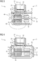
- FIG. 3 An improved with respect to the shielding effect of the antenna base plate 26 embodiment of the speaker module 1 is in Fig. 3 shown.
- the coil core 24 and thus the antenna coil 20 is positioned on the antenna base plate 26 in such a way that the coil axis 22 of the antenna coil 20 intersects the drive coil 16 of the loudspeaker 3.
- the coil axis 22 of the antenna coil 20 is aligned centrally to the drive coil 16 and also cuts the coil axis 18 of the drive coil 16 (in the middle of the drive coil 16). This results in a particularly favorable course of the magnetic field of the drive coil 16 (represented by schematically indicated magnetic field lines 40).
- FIG. 3 An improved with respect to the shielding effect of the antenna base plate 26 embodiment of the speaker module 1 is in Fig. 3 shown.
- the coil core 24 and thus the antenna coil 20 is positioned on the antenna base plate 26 in such a way that the coil axis 22 of the antenna coil 20 intersects the drive coil 16 of the loudspeaker 3.
- Upper magnetic field lines 40 (ie, the magnetic coil lines 40 closer to the antenna coil 20) are deflected by the antenna base plate 26 such that they are short-circuited approximately transversely (at right angles) to the coil axis 22 of the antenna coil 20. This results in particularly low interference from the magnetic field of the drive coil 16 to the antenna characteristic of the antenna unit 5.
- the coil core 24 with respect to the antenna base plate 26 at a small distance, for example by means of a film positioned. The magnetic field of the drive coil 16 is thereby additionally shielded from the antenna coil 20 with increased attenuation.
- the antenna unit 5 additionally comprises antenna side plates 42 which are arranged on the antenna coil 20 side facing away from the antenna base plate 26 angled to the latter and placed concretely on the outside of the housing 4.
- the antenna magnetic field generated by the antenna unit 20 is advantageously conducted around the loudspeaker 3 through these antenna side plates 42.
- the antenna side plates 42 also contribute to shielding the magnetic field of the drive coil 15 from the antenna coil 20.
- the antenna side plates 42 and the bobbin 24 are each spaced at a small distance from the antenna base plate 26.
- the corresponding distance is realized for example by an adhesive layer or by an interposed foil.
- the antenna side plates 42 and the bobbin 24, however, are in direct contact with the antenna base plate 26.
- the antenna side plates 42 are not placed on the housing 4, but form the respective perpendicular to the antenna base plate 26 side walls of the housing 4 itself.
- the antenna side plates 42 and the antenna base plate 26 are hereby made as an integral unit.
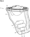
- the hearing device 2 shown represents a so-called in-the-ear hearing device (short IDO hearing aid).
- the hearing aid 2 comprises a hearing aid housing 50 which is adapted to the shape of the auditory canal of the hearing device wearer and faces away from the eardrum of the hearing aid wearer at its intended wearing position End is closed by a front panel (referred to as "face plate" 52).
- face plate a front panel
- the eardrum end facing the hearing aid housing 50 has a sound output 54.
- Housing inside is the speaker module 1 with the sound channel 32 forming bobbin 24 of the antenna unit 5 in this sound output 54 arranged.
- an electronics unit 56 which is circuitry coupled to the speaker module 1 and carries the elements for signal processing.
Description
Die Erfindung betrifft ein Lautsprechermodul für ein Hörgerät. Des Weiteren betrifft die Erfindung ein Hörgerät mit einem solchen Lautsprechermodul.The invention relates to a loudspeaker module for a hearing aid. Furthermore, the invention relates to a hearing aid with such a loudspeaker module.
Unter den Begriff "Hörgerät" fallen insbesondere Hörhilfegeräte, die Personen mit einer Hörminderung dazu dienen, diese Hörminderung zumindest teilweise auszugleichen. Dazu umfassen Hörhilfegeräte als Komponenten üblicherweise wenigstens ein Mikrofon zur Aufnahme von akustischen Tonsignalen (z.B. Stimmen, Musik und/oder sonstigen Umgebungsgeräuschen), eine Signalverarbeitungseinheit (auch als Signalprozessor bezeichnet) zur Filterung und zumindest teilweisen Verstärkung der aufgenommenen Tonsignale sowie einen (meist auch als "Hörer" bezeichneten) Lautsprecher zur Ausgabe der verarbeiteten Tonsignale an ein Ohr eines Hörgeräteträgers (d.h. der Person mit Hörminderung). Alternativ zu dem Lautsprecher umfassen Hörhilfegeräte - je nach Art der Hörminderung - beispielsweise ein Knochenleitungs- oder Kochlea-Implantat zur mechanischen bzw. elektrischen Stimulation des Hörzentrums des Hörgeräteträgers. Unter den Begriff "Hörgerät" fallen jedoch auch andere Geräte, die zur Ausgabe von (akustischen) Tonsignalen an das Gehör des entsprechenden Hörgeräteträgers dienen. Derartige Geräte sind beispielsweise sogenannte Tinnitus-Masker, Kopfhörer, Headsets und dergleichen.The term "hearing aid" includes in particular hearing aid devices that serve people with a hearing loss to compensate for this hearing loss at least partially. For this purpose, hearing aid devices usually comprise as components at least one microphone for recording acoustic sound signals (eg voices, music and / or other environmental noises), a signal processing unit (also referred to as signal processor) for filtering and at least partially amplifying the recorded sound signals and a (usually also as " Handset "speakers) for outputting the processed sound signals to an ear of a hearing aid wearer (ie the person with hearing loss). As an alternative to the loudspeaker, hearing aid devices include, for example, a bone conduction or cochlear implant, depending on the type of hearing loss, for the mechanical or electrical stimulation of the hearing center of the hearing device wearer. However, the term "hearing aid" also includes other devices that are used to output (acoustic) sound signals to the hearing of the corresponding hearing aid wearer. Such devices are, for example, so-called tinnitus maskers, headphones, headsets and the like.
Ein Hörgerät, insbesondere ein Hörhilfegerät, kann beispielsweise als einzelnes, "monaurales" Hörhilfegerät zur unabhängigen Versorgung eines Ohrs des Hörgeräteträgers ausgebildet sein. In ein solches monaurales Hörgerät bzw. Hörhilfegerät sind dabei üblicherweise alle vorstehend beschriebenen Komponenten integriert. Das Hörgerät bzw. Hörhilfegerät kann aber auch Teil eines binauralen Hörgerätesystems sein. Ein solches binaurales Hörgerätesystem ist dabei regelmäßig zur Versorgung beider Ohren des Hörgeräteträgers eingerichtet. Dabei findet üblicherweise zwischen den beiden (binauralen) Hörgeräten ein Datenaustausch (Signalaustausch) statt, der die eigentliche binaurale Signalverarbeitung ermöglicht. So sind binaurale Hörgeräte häufig mit Signalverarbeitungsalgorithmen ausgestattet, mittels derer beispielsweise zur Erzeugung einer Richtwirkung die von beiden Hörgeräten empfangenen Tonsignale berücksichtigt werden. Dazu müssen die Tonsignale erkanntermaßen zwischen den Hörgeräten übertragen werden.A hearing aid, in particular a hearing aid, can be designed, for example, as a single, "monaural" hearing aid for the independent supply of an ear of the hearing aid wearer. In such a monaural hearing aid or hearing aid device usually all components described above are integrated. The hearing aid or hearing aid can also be part of a binaural hearing aid system his. Such a binaural hearing device system is regularly set up to supply both ears of the hearing device wearer. In this case, usually between the two (binaural) hearing aids, a data exchange (signal exchange) takes place, which allows the actual binaural signal processing. Thus, binaural hearing aids are often equipped with signal processing algorithms, by means of which, for example, to generate a directional effect, the sound signals received by both hearing aids are taken into account. For this purpose, the sound signals must be transmitted between the hearing aids recognized.
Der Datenaustausch zwischen den beiden binauralen Hörgeräten erfolgt dabei regelmäßig über ein Funksystem. Das heißt, dass beide binaurale Hörgeräte zumindest eine Antenne zum Senden und/oder Empfangen der auszutauschenden Daten aufweisen. Diese Antennen stellen jedoch ein zu den vorstehend beschriebenen Komponenten zusätzliches Bauteil dar, das erkanntermaßen innerhalb eines Hörgerätegehäuses (zumindest innerhalb des für das Hörgerät zur Verfügung stehenden Bauraums) platziert werden muss. Um eine hinreichend hohe Qualität im Hinblick auf das Senden und Empfangen der auszutauschenden Daten aufrechterhalten zu können, kann jedoch eine gewisse Größe (insbesondere ein gewisses Volumen) der Antenne nicht unterschritten werden. Der somit für die Antenne benötigte Platzbedarf läuft allerdings den Bestrebungen, Hörgeräte aller Bauarten (z.B. Hinter-dem-Ohr-, In-dem-Ohr- oder Im-Kanal-Hörgeräte) mit immer kleineren Gehäusevolumina zu versehen, zuwider. Denn andere Hörgerätekomponenten, wie insbesondere der Lautsprecher, können nicht beliebig verkleinert werden, da ansonsten die Klangqualität und die Effizienz der ausgegebenen Tonsignale abnehmen würde. Aus
Die Klangqualität ist allerdings eines der Hauptqualitätsmerkmale, die der Hörgeräteträger beim Gebrauch eines Hörgeräts wahrnimmt. Die Klangcharakteristik und die Effizienz in tiefen Frequenzen (und damit die subjektiv empfundene Klangqualität) eines Lautsprechers wird dabei insbesondere durch ein Rückvolumen (auch als "back volume" bezeichnet), das üblicherweise durch ein Volumen gebildet ist, das von einer die Tonsignale erzeugenden Lautsprechermembran gegenüber der Umgebung abgegrenzt wird, sowie durch ein Frontvolumen (auch als "front volume" bezeichnet), das zwischen der Lautsprechermembran und dem Schallauslass des Hörers bzw. zwischen dem Schallauslass des Hörers und dem Trommelfell angeordnet ist, beeinflusst. Insbesondere wirkt sich hierbei das Verhältnis aus Rückvolumen und Frontvolumen auf die Klagqualität und Effizienz des Hörers aus. Üblicherweise bezieht sich hierbei der Begriff des Frontvolumens auf das Volumen zwischen der Lautsprechermembran und dem Schallauslass des Hörers. Übliche in einem Hörgerät eingesetzte Lautsprecher sind meist innerhalb des Hörgerätegehäuses angeordnet und mittels eines Schallstutzens oder eines Schallschlauchs, der einen Schallkanal bildet, mit einem Schallausgang des Hörgerätegehäuses verbunden. Das zwischen der Lautsprechermembran und dem Schallausgang angeordnete Volumen stellt daher folglich das Frontvolumen in diesem Sinne dar.However, the sound quality is one of the main quality features that the hearing aid wearer perceives when using a hearing aid. The sound characteristics and the efficiency in low frequencies (and thus the subjectively perceived Sound quality) of a loudspeaker is characterized in particular by a back volume (also referred to as "back volume"), which is usually formed by a volume which is delimited by a sound signal generating loudspeaker membrane from the environment, and by a front volume (also referred to as "front volume"), which is arranged between the loudspeaker diaphragm and the sound outlet of the listener or between the sound outlet of the listener and the eardrum. In particular, the ratio of back volume and front volume has an effect on the quality of complaint and the efficiency of the listener. Usually, the term of the front volume refers to the volume between the loudspeaker diaphragm and the sound outlet of the listener. Conventional loudspeakers used in a hearing device are usually arranged inside the hearing device housing and are connected to a sound output of the hearing device housing by means of a sound socket or a sound tube which forms a sound channel. The volume arranged between the loudspeaker diaphragm and the sound outlet therefore consequently represents the front volume in this sense.
Der Erfindung liegt die Aufgabe zugrunde, bei einem zur funkbasierten Datenübertragung eingerichteten Hörgerät eine verbesserte Klangcharakteristik zu ermöglichen.The object of the invention is to enable an improved sound characteristic in a hearing device equipped for radio-based data transmission.
Diese Aufgabe wird erfindungsgemäß gelöst durch ein Lautsprechermodul mit den Merkmalen des Anspruchs 1. Weiterhin wird die Aufgabe erfindungsgemäß gelöst durch ein Hörgerät mit den Merkmalen des Anspruchs 10. Vorteilhafte und teils für sich erfinderische Ausführungsformen und Weiterentwicklungen der Erfindung sind in den Unteransprüchen und der nachfolgenden Beschreibung dargelegt.This object is achieved by a loudspeaker module with the features of
Das erfindungsgemäße Lautsprechermodul ist für den Einsatz in einem Hörgerät mit funkbasierter Datenübertragung eingerichtet und vorgesehen. Das Lautsprechermodul umfasst dabei einen Lautsprecher, der eine Lautsprechermembran und einen Antrieb für diese Lautsprechermembran (im Folgenden: Membranantrieb) umfasst. Des Weiteren umfasst das Lautsprechermodul ein Gehäuse, in dem der Lautsprecher angeordnet ist. Vorzugsweise umschließt das Gehäuse den Lautsprecher dabei allseitig bis auf eine Öffnung, durch die hindurch im Betrieb des Lautsprechers akustische Signale in die Umgebung austreten können. Das Lautsprechermodul umfasst außerdem eine Antenneneinheit zum Senden und/oder Empfangen von elektromagnetischen Signalen. Diese Antenneneinheit weist dabei eine Antennenspule mit einer Spulenachse und einen rohrförmigen Spulenkern, auf den die Antennenspule aufgewickelt ist und der einen Schallkanal bildet, auf. Der Begriff "rohrförmig" ist hierbei ohne eine Beschränkung auf eine spezifische Querschnittsform des Rohrs zu verstehen. So hat der sich rohrförmig erstreckende Spulenkern insbesondere einen quadratischen, rechteckigen, mehreckigen, ovalen oder runden Querschnitt. In einer möglichen Ausführungsform variiert die Querschnittsform entlang des Spulenkerns. Die Antennenspule erstreckt sich dabei entlang ihrer Spulenachse vorzugsweise geradlinig. Des Weiteren weist die Antenneneinheit eine Antennengrundplatte auf, in der eine in den Schallkanal des Spulenkerns mündende Schalldurchtrittsöffnung ausgebildet ist. Die Antennenspule, der Spulenkern sowie die Antennengrundplatte geben dabei eine Antennencharakteristik der Antenneneinheit vor. Die Seitenwand des Gehäuses auf der Membranseite - d.h. die der Lautsprechermembran(-Oberfläche) gegenüberliegende Seitenwand - ist dabei durch die Antennengrundplatte gebildet.The loudspeaker module according to the invention is set up and provided for use in a hearing device with radio-based data transmission. The loudspeaker module in this case comprises a loudspeaker comprising a loudspeaker diaphragm and a drive for this loudspeaker diaphragm (in the following: diaphragm drive). Furthermore, the speaker module comprises a housing in which the speaker is arranged. The housing preferably encloses the loudspeaker on all sides except for an opening through which acoustic signals can escape into the environment during operation of the loudspeaker. The speaker module also includes an antenna unit for transmitting and / or receiving electromagnetic signals. This antenna unit has an antenna coil with a coil axis and a tubular coil core on which the antenna coil is wound and which forms a sound channel on. The term "tubular" is to be understood without any limitation to a specific cross-sectional shape of the tube. Thus, the tubular extending coil core in particular a square, rectangular, polygonal, oval or round cross-section. In one possible embodiment, the cross-sectional shape varies along the spool core. The antenna coil preferably extends in a straight line along its coil axis. Furthermore, the antenna unit has an antenna base plate, in which a sound passage opening opening into the sound channel of the coil core is formed. The antenna coil, the coil core and the antenna base plate specify an antenna characteristic of the antenna unit. The side wall of the housing on the membrane side - ie the speaker membrane (surface) opposite side wall - is formed by the antenna base plate.
Das heißt, dass das Lautsprechermodul eine aus dem Lautsprecher und der Antenneneinheit gebildete Baueinheit darstellt, bei der die Antenneneinheit in das Gehäuse des Lautsprechers integriert ist. Eine Schallaustrittsöffnung des Lautsprechermoduls, durch die der von der Lautsprechermembran erzeugte Schall in die Umgebung abgegeben werden kann, ist dabei vorzugsweise durch das der Antennengrundplatte abgewandte Freiende des Schallkanals gebildet (d h. an dem Freiende des Spulenkerns angeordnet). Insbesondere sind dem Lautsprecher und der Antenneneinheit, konkret der Antennengrundplatte keine zusätzlichen Gehäuseteile zwischengeordnet.That is, the speaker module is a unit formed of the speaker and the antenna unit, in which the antenna unit is integrated with the case of the speaker. A sound exit opening of the loudspeaker module, by means of which the sound generated by the loudspeaker membrane can be emitted into the environment, is preferably formed by the free end of the sound channel facing away from the antenna base plate (ie arranged at the free end of the coil core). In particular, no additional housing parts are interposed between the loudspeaker and the antenna unit, specifically the antenna base plate.
Unter "Antennencharakteristik" werden hier und im Folgenden insbesondere Leistungsmerkmale der Antenneneinheit verstanden, wie z.B. eine (möglichst geringe aufzuwendende, elektrische) Sendeleistung zur Datenübertragung an einen Empfänger, eine hohe Empfangsleistung sowie eine geringe Störanfälligkeit.By "antenna characteristics" is meant here and below in particular features of the antenna unit, such as e.g. a (as low as possible, electrical) transmission power for data transmission to a receiver, a high reception power and a low susceptibility to interference.
Dadurch, dass der Schallkanal durch den mit der Antennenspule bewickelten Spulenkern gebildet ist, kann für eine separate Antenne erforderlicher Bauraum eingespart werden und somit der in dem Hörgerätegehäuse verbleibende Bauraum ohne Auswirkungen auf das Volumen des Lautsprechers, insbesondere auf das Rückvolumen, verkleinert oder alternativ ein Lautsprecher mit entsprechend vergrößertem Rückvolumen verbaut werden. Dadurch, dass die Antennengrundplatte eine Seitenwand des Lautsprechergehäuses bildet, kann vorteilhafterweise bei gleich bleibendem Antennenvolumen, insbesondere bei gleich bleibender Länge des Spulenkerns das zu einem Großteil durch den Schallkanal gebildete Frontvolumen im Verhältnis zu dem Rückvolumen reduziert werden. Die Antenneneinheit rückt näher an die Lautsprechermembran. Dadurch wird vorteilhafterweise der akustische Widerstand für die Lautsprechermembran herabgesetzt und folglich die Klangcharakteristik des Lautsprechers verbessert. Die Erfindung geht dabei von der eigenen Erkenntnis aus, dass eine Verkleinerung des Frontvolumens und eine Vergrößerung des Rückvolumens die Bandbreite und die Effizienz des Lautsprechers in tiefen Frequenzen erhöht. Zudem kann der Lautsprecher bei gleichbleibender oder sogar verringerter Baugröße (sowie insbesondere bei gleichbleibender elektrischer Leistung) eine höhere (Schallausgangs-) Leistung aufweisen. Zusätzlich ergibt sich durch die Integration der Antennengrundplatte in das Gehäuse des Lautsprechermoduls eine insgesamt möglichst kurze Baulänge des Lautsprechermoduls (insbesondere entlang der Spulenachse der Antennenspule), die hinsichtlich einer kompakten Gestaltung des gesamten Hörgeräts vorteilhaft ist.Due to the fact that the sound channel is formed by the coil core wound with the antenna coil, it is possible to save space required for a separate antenna and thus the installation space remaining in the hearing aid housing without affecting the volume of the speaker, especially on the back volume, reduced or alternatively a speaker with a correspondingly increased back volume are installed. Due to the fact that the antenna base plate forms a side wall of the loudspeaker housing, the front volume, which is largely formed by the sound channel, can advantageously be reduced in relation to the back volume while maintaining the same antenna volume, in particular with the coil core remaining the same length. The antenna unit moves closer to the speaker membrane. This advantageously reduces the acoustic resistance for the loudspeaker diaphragm and consequently improves the sound characteristic of the loudspeaker. The invention is based on the own knowledge that a reduction of the front volume and an increase of the back volume increases the bandwidth and the efficiency of the speaker in low frequencies. In addition, the loudspeaker can have a higher (sound output) performance with a constant or even reduced size (and in particular with constant electrical power). In addition, the integration of the antenna baseplate into the housing of the loudspeaker module results in an overall shortest possible length of the loudspeaker module (in particular along the coil axis of the antenna coil), which is advantageous in terms of a compact design of the entire hearing device.
In einer bevorzugten Ausführung ist die Lautsprechermembran derart im Gehäuse befestigt, dass hierdurch der Schallkanal gegenüber dem Gehäuseinnenraum abgetrennt ist. Das heißt, dass der Gehäuseinnenraum das Rückvolumen bildet. Die Lautsprechermembran verschließt den Schallkanal gegenüber dem Gehäuseinnenraum. Die Lautsprechermembran ist bis auf einen notwendigen Schwingungsabstand unmittelbar an die Antennengrundplatte gerückt. Dazu ist die Lautsprechermembran beispielsweise über einen insbesondere metallischen Randbereich an den seitlichen Wänden des Gehäuses befestigt oder sie ist unmittelbar an der Antennengrundplatte montiert. Dadurch wird einerseits gegenüber einer üblichen Lautsprecherkonstruktion, bei der die Lautsprechermembran gegenüber dem Schallkanal deutlich in den Innenraum des (meist quaderförmigen) Gehäuses versetzt aufgespannt ist und dabei den von den (Gehäuse-)Seitenwänden umgebenen Gehäuseinnenraum in zwei Teilvolumina unterteilt, das von der Lautsprechermembran von der Umgebung, hier konkret dem Schallkanal, abgetrennte Rückvolumen, insbesondere in Bezug zum Frontvolumen, vergrößert. Das Frontvolumen ist auf das ohnehin in dem Spulenkern vorhandene Volumen verkleinert. Durch ein vergrößertes Rückvolumen wird ebenfalls der akustische Widerstand für die Lautsprechermembran bei Erzeugung der akustischen (Ausgangs-)Signale herabgesetzt. Insbesondere werden durch ein vergrößertes Rückvolumen die Tieftoneigenschaften des Lautsprechers verbessert.In a preferred embodiment, the loudspeaker diaphragm is fastened in the housing in such a way that the sound channel is thereby separated from the interior of the housing. This means that the housing interior forms the back volume. The loudspeaker diaphragm seals the sound channel with respect to the interior of the housing. The loudspeaker diaphragm is moved directly to the antenna base plate except for a necessary oscillation distance. For this purpose, the loudspeaker diaphragm is fastened to the side walls of the housing, for example via a particularly metallic edge region, or it is mounted directly on the antenna baseplate. As a result, on the one hand compared to a conventional speaker construction, in which the loudspeaker diaphragm is clearly offset from the sound channel in the interior of the (usually cuboid) housing spanned while the from the (housing) side walls Surrounding housing interior divided into two sub-volumes, the volume of the loudspeaker from the environment, here specifically the sound channel, separated back volume, especially in relation to the front volume, increases. The front volume is reduced to the volume already present in the spool core. An increased back volume also reduces the acoustic resistance for the speaker diaphragm when generating the acoustic (output) signals. In particular, the bass characteristics of the loudspeaker are improved by an increased back volume.
In einer besonders zweckmäßigen Ausführung ist die Lautsprechermembran in dem Spulenkern (d. h. innerhalb des Spulenkerns) angeordnet. Vorzugsweise ist die Lautsprechermembran dabei radial zur Spulenachse der Antennenspule angeordnet. In dieser Ausführung ist das Rückvolumen weiter vergrößert und der von der Lautsprechermembran gegenüber dem Gehäuseinnenraum abgegrenzte Schallkanal und somit das in dem Schallkanal angeordnete Frontvolumen entsprechend weiter verkleinert, sodass die Klangcharakteristik des Lautsprechers weiter verbessert wird. Insbesondere können durch die Volumenänderung des Rückvolumens und des Frontvolumens vorteilhafterweise sowohl hohe als auch tiefe Frequenzen besser (vorzugsweise mit klarem Klang) dargeboten werden.In a particularly expedient embodiment, the loudspeaker diaphragm is arranged in the coil core (that is to say inside the coil core). Preferably, the speaker diaphragm is arranged radially to the coil axis of the antenna coil. In this embodiment, the back volume is further increased and the sound channel delimited by the loudspeaker diaphragm from the interior of the housing, and thus the front volume arranged in the sound channel, are correspondingly further reduced, so that the sound characteristic of the loudspeaker is further improved. In particular, due to the volume change of the back volume and the front volume advantageously both high and low frequencies can be presented better (preferably with a clear sound).
In einer weiteren zweckmäßigen Ausführung umfasst der Membranantrieb eine Antriebsspule mit einer Spulenachse. Vorzugsweise ist die Antriebsspule entlang ihrer Spulenachse insbesondere geradlinig langgestreckt, d. h. die Antriebsspule weist im Vergleich zu ihrer Erstreckung quer zur Spulenachse (auch als "Dicke" bezeichnet) eine größere Länge auf. Die Spulenachse der Antennenspule ist in dieser Ausführung vorzugsweise senkrecht zu der Spulenachse der Antriebsspule ausgerichtet. In diesem Fall ist zweckmäßigerweise auch die Antennengrundplatte senkrecht zur der Spulenachse der Antennenspule angeordnet. Dadurch, dass die Antennenspule und die Antriebsspule (bzw. deren jeweilige Spulenachsen) senkrecht zueinander ausgerichtet sind, wird im Betrieb der jeweiligen Spule eine Einkopplung des von dieser Spule erzeugten Magnetfelds in die entsprechende andere Spule vorteilhaft verringert. Insbesondere kann dadurch eine störende Induktion von Strömen durch das Magnetfeld einer Spule in der entsprechend anderen Spule vorteilhaft reduziert werden. Somit wird insbesondere eine Störung der Antenne durch das Magnetfeld der Antriebsspule verringert und somit die Qualität der Datenübertragung der Antenneneinheit erhöht.In a further expedient embodiment, the membrane drive comprises a drive coil with a coil axis. Preferably, the drive coil along its coil axis is in particular straight elongated, that is, the drive coil has in comparison to their extent transverse to the coil axis (also referred to as "thickness") a greater length. The coil axis of the antenna coil is preferably aligned perpendicular to the coil axis of the drive coil in this embodiment. In this case, the antenna base plate is expediently arranged perpendicular to the coil axis of the antenna coil. Characterized in that the antenna coil and the drive coil (or their respective coil axes) are aligned perpendicular to each other, a coupling of the magnetic field generated by this coil in the corresponding other coil is advantageously reduced during operation of the respective coil. In particular, this can be a disturbing induction of currents through the magnetic field of a coil in the other Coil advantageously be reduced. Thus, especially a disturbance of the antenna is reduced by the magnetic field of the drive coil and thus increases the quality of the data transmission of the antenna unit.
In einer bevorzugten Weiterbildung der vorstehend beschriebenen Ausführung stehen die jeweiligen Spulenachsen der Antennenspule und der Antriebsspule aufeinander senkrecht. Mit anderen Worten schneiden sich die beiden Spulenachsen mit einem Winkel von 90°.In a preferred embodiment of the embodiment described above, the respective coil axes of the antenna coil and the drive coil are perpendicular to each other. In other words, the two coil axes intersect at an angle of 90 °.
In einer bevorzugten Ausführung sind der Spulenkern sowie die Antennengrundplatte aus ferromagnetischem und/oder ferrimagnetischem Material ausgebildet. Vorzugsweise sind der Spulenkern und die Antennengrundplatte dabei aus Ferrit gebildet. Aufgrund der dadurch vorhandenen magnetischen Eigenschaften tragen somit sowohl der Spulenkern als auch die Antennengrundplatte besonders vorteilhaft zur Antennencharakteristik der Antenneneinheit bei. In dieser Ausführung handelt es sich bei der Antenneneinheit vorzugsweise um eine magnetische Antenne, insbesondere um eine "Ferritantenne". Derartige Antennen eignen sich vorteilhafterweise besonders gut zur Signalübertragung in einem Frequenzbereich zwischen vorzugsweise etwa 100 kHz bis 10 MHz. Diese Antennen ermöglichen nämlich eine Datenübertragung über vergleichsweise kurze Entfernungen, wie z.B. in der Größenordnung des Abstands der beiden Ohren eines Menschen zueinander, bei gleichzeitig (insbesondere im Vergleich zu hochfrequenten Datenübertragungssystemen) niedriger elektrischer Leistungsaufnahme. Insbesondere werden die bei diesen Antennen zur Datenübertragung genutzten magnetischen Felder durch das zwischen der sendenden und der empfangenden Antenne angeordnete Körpergewebe (insbesondere den Kopf) in diesem vergleichsweise niedrigen Frequenzbereich vorteilhafterweise nicht oder nur zu einem vernachlässigbaren Anteil gedämpft. Zudem weist die magnetische Antenne vorteilhafterweise auch eine im Vergleich zu einer Antenne für ein elektrisches Feld kleinere Baugröße auf, was wiederum zur Einsparung von Bauraum beiträgt. Des Weiteren wirkt in dieser Ausführung die Antennengrundplatte vorteilhafterweise als eine Art magnetischer Schirm zwischen der Antriebsspule und der Antennenspule. Insbesondere schließt die Antennengrundplatte aufgrund ihrer zu der Spulenachse der Antriebsspule parallelen Anordnung - und damit ihrer senkrechten Ausrichtung zur Antennenspule - das Magnetfeld der Antriebsspule zumindest zu großen Teilen quer zur Spulenachse der Antennenspule kurz, sodass eine Einkopplung des Magnetfelds der Antriebsspule und dadurch induzierte Ströme in der Antennenspule vernachlässigbar gering sind. Somit wird die Qualität der Datenübertragung der Antenneneinheit (insbesondere deren Robustheit gegen störende Magnetfelder) weiter erhöht.In a preferred embodiment, the coil core and the antenna base plate are formed from ferromagnetic and / or ferrimagnetic material. Preferably, the coil core and the antenna base plate are formed from ferrite. Due to the magnetic properties present thereby, both the coil core and the antenna base plate thus contribute particularly advantageously to the antenna characteristic of the antenna unit. In this embodiment, the antenna unit is preferably a magnetic antenna, in particular a "ferrite antenna". Such antennas are advantageously particularly well suited for signal transmission in a frequency range between preferably about 100 kHz to 10 MHz. Namely, these antennas enable data transmission over relatively short distances, such as the order of magnitude of the distance between the two ears of a human being to each other, while at the same time (in particular compared to high-frequency data transmission systems) low electrical power consumption. In particular, the magnetic fields used for data transmission in these antennas are advantageously not or only to a negligible extent dampened by the body tissue (in particular the head) arranged between the transmitting and the receiving antenna in this comparatively low frequency range. In addition, the magnetic antenna advantageously also has a smaller size compared to an antenna for an electric field, which in turn contributes to the saving of installation space. Furthermore, in this embodiment, the antenna base plate advantageously acts as a kind of magnetic shield between the drive coil and the antenna coil. In particular, the antenna baseplate closes due to its to the coil axis of the Drive coil parallel arrangement - and thus their vertical orientation to the antenna coil - the magnetic field of the drive coil at least transversely to the coil axis of the antenna coil at least largely so that a coupling of the magnetic field of the drive coil and thereby induced currents in the antenna coil are negligible. Thus, the quality of the data transmission of the antenna unit (in particular their robustness against interfering magnetic fields) is further increased.
In einer weiteren zweckmäßigen Ausführung ist der Spulenkern der Antenneneinheit insbesondere derart angeordnet, dass die Spulenachse der Antennenspule die Antriebsspule schneidet. Dadurch wird die Schirmwirkung der Antennengrundplatte weiter verbessert und somit die Einkopplung des magnetischen Felds der Antriebsspule in die Antennenspule weiter verringert.In a further expedient embodiment, the coil core of the antenna unit is arranged in particular such that the coil axis of the antenna coil intersects the drive coil. As a result, the shielding effect of the antenna base plate is further improved and thus further reduces the coupling of the magnetic field of the drive coil into the antenna coil.
In einer bevorzugten Weiterbildung ist der Spulenkern vorzugsweise derart angeordnet, dass die Spulenachse der Antennenspule im Wesentlichen - d.h. exakt oder näherungsweise, insbesondere mit einem gegenüber der Länge der Antriebsspule um ein Vielfaches kleineren Abstand - mittig zur Antriebsspule verläuft. Dadurch wird eine auch als "magnetisch symmetrisch" bezeichnete Anordnung der jeweiligen Magnetfelder der Antriebsspule und der Antennenspule erreicht, durch die insbesondere in Kombination mit der ferro- und/oder ferrimagnetischen Antennengrundplatte vorteilhafterweise eine besonders hohe Schirmwirkung bzw. eine vernachlässigbar geringe Einkopplung des Magnetfelds der Antriebsspule in die Antennenspule ermöglicht wird.In a preferred development, the coil core is preferably arranged such that the coil axis of the antenna coil essentially - i. exactly or approximately, in particular with respect to the length of the drive coil by a multiple smaller distance - runs centrally to the drive coil. As a result, an arrangement of the respective magnetic fields of the drive coil and the antenna coil, which is also referred to as "magnetically symmetrical", is advantageously achieved, in particular in combination with the ferromagnetic and / or ferrimagnetic antenna base plate, a particularly high shielding effect or a negligible coupling of the magnetic field of the drive coil is made possible in the antenna coil.
In einer weiteren zweckmäßigen Ausführung umfasst die Antenneneinheit wenigstens eine Antennenseitenplatte, die sich auf einer der Antennenspule abgewandten Seite der Antennengrundplatte abgewinkelt zur Antennengrundplatte, vorzugsweise senkrecht zu dieser erstreckt. Zweckmäßigerweise deckt die oder die jeweilige Antennenseitenplatte eine (zu der vorstehenden beschriebenen membranseitigen Seitenwand weitere) Seitenwand des Gehäuses ab. Des Weiteren ist die oder die jeweilige Antennenseitenplatte vorzugsweise aus dem gleichen Material wie der Spulenkern und die Antennengrundplatte gebildet. Die Antennenseitenplatte führt dabei vorteilhafterweise zu einer Verlängerung der Antenneneinheit (insbesondere entlang der Spulenachse der Antennenspule) und somit zu einer weiteren Verbesserung der Antennencharakteristik. Des Weiteren wird das von der Antennenspule erzeugte Magnetfeld aufgrund der Anordnung der oder der jeweiligen Antennenseitenplatte um den Lautsprecher herumgeführt. Des Weiteren trägt die oder die jeweilige Antennenseitenplatte auch zur Schirmwirkung der Antennengrundplatte und somit zur Abschirmung des von der Antriebsspule erzeugten Magnetfelds gegenüber der Antennenspule bei.In a further expedient embodiment, the antenna unit comprises at least one antenna side plate, which extends at an angle away from the antenna coil side of the antenna base plate angled to the antenna base plate, preferably perpendicular to this. The respective antenna side plate expediently covers a side wall of the housing (further to the above-described membrane-side side wall). Further, the respective antenna side plate or plates are preferably formed of the same material as the coil core and the antenna base plate. The antenna side plate leads advantageously to an extension of the antenna unit (in particular along the coil axis of the antenna coil) and thus to a further improvement of the antenna characteristic. Further, the magnetic field generated by the antenna coil is guided around the speaker due to the arrangement of the respective antenna side plate. Furthermore, the respective antenna side plate also contributes to the screening effect of the antenna base plate and thus to the shielding of the magnetic field generated by the drive coil relative to the antenna coil.
Zur weiteren konstruktiven Integration des Lautsprechermoduls ist in einer zweckmäßigen Weiterbildung der vorstehend beschriebenen Ausführung wenigstens eine der vorstehend beschriebenen weiteren Seitenwände des Gehäuses durch die oder jeweils eine Antennenseitenplatte gebildet. Das heißt, dass diese Seitenwand des Gehäuses entfällt und durch die Antennenseitenplatte ersetzt ist. Für den Fall, dass die Antenneneinheit insbesondere vier der vorstehend beschriebenen Antennenseitenplatten umfasst, bilden diese im Fall der vorliegenden Weiterbildung einen schachtel- oder becherartigen Teil des Gehäuses.For further constructional integration of the loudspeaker module, in an expedient development of the embodiment described above, at least one of the further side walls of the housing described above is formed by the or each antenna side plate. This means that this side wall of the housing is eliminated and replaced by the antenna side plate. In the event that the antenna unit in particular comprises four of the antenna side plates described above, these form in the case of the present development, a box-like or cup-like part of the housing.
In einer weiteren zweckmäßigen Ausführung ist die Antennengrundplatte mit Abstand, beispielsweise im Bereich von 50 bis 150 µm, insbesondere von etwa 100 µm, mit dem Spulenkern und/oder gegebenenfalls mit der oder der jeweiligen Antennenseitenplatte verbunden. Mit anderen Worten stehen die Antennengrundplatte, der Spulenkern sowie gegebenenfalls die oder die jeweilige Antennenseitenplatte nicht unmittelbar miteinander in Kontakt, sondern sind beispielsweise mittels einer Klebeschicht und/oder andersartigen isolierenden Zwischenstücken - beispielsweise Kunststoff - voneinander beabstandet und zueinander gehaltert. Dadurch wird vorteilhafterweise ein hohes Signal-Rausch-Verhältnis der Antenneneinheit, d. h. ein besonders störungsfreier Empfang erreicht. Das Magnetfeld der Antriebsspule des Lautsprechers wird gegenüber der Antenne mit einer besseren Dämpfung abgeschirmt.In a further expedient embodiment, the antenna base plate is connected at a distance, for example in the range of 50 to 150 .mu.m, in particular of about 100 .mu.m, to the spool core and / or optionally to the or the respective antenna side plate. In other words, the antenna base plate, the coil core and optionally the respective antenna side plate or plates are not directly in contact with each other, but are spaced apart from one another and held to one another, for example by means of an adhesive layer and / or different insulating spacers - for example plastic. This advantageously results in a high signal-to-noise ratio of the antenna unit, i. H. achieved a particularly trouble-free reception. The magnetic field of the drive coil of the speaker is shielded from the antenna with better damping.
Bei dem Lautsprecher handelt es sich in einer bevorzugten Ausführung um einen sogenannten "balanced armature"-Lautsprecher oder um einen "moving armature"-Lautsprecher. In beiden Fällen umfasst der Lautsprecher, insbesondere dessen Membranantrieb, zusätzlich zu der Antriebsspule zwei Permanentmagnete sowie einen Anker, der in einem Spalt zwischen den beiden Permanentmagneten angeordnet ist und der über eine "Antriebsstange" mit der Lautsprechermembran gekoppelt ist. Der Anker durchläuft außerdem die Antriebsspule.In a preferred embodiment, the loudspeaker is a so-called "balanced armature" loudspeaker or a "moving" loudspeaker In both cases, the loudspeaker, in particular its diaphragm drive, comprises in addition to the drive coil two permanent magnets and an armature which is arranged in a gap between the two permanent magnets and which is coupled to the loudspeaker diaphragm via a "drive rod" Anchor also passes through the drive coil.
Das erfindungsgemäße Hörgerät umfasst ein Lautsprechermodul der vorstehend beschriebenen Art, sowie vorzugsweise ein (Hörgeräte-)Gehäuse, in dem das Lautsprechermodul angeordnet ist. Vorzugsweise ist dabei das Lautsprechermodul mit seinem Schallkanal in einer Schallausgangsöffnung des Hörgerätegehäuses positioniert.The hearing aid according to the invention comprises a loudspeaker module of the type described above, and preferably a (hearing aid) housing in which the loudspeaker module is arranged. In this case, the loudspeaker module is preferably positioned with its sound channel in a sound exit opening of the hearing device housing.
Nachfolgend werden Ausführungsbeispiele der Erfindung anhand einer Zeichnung näher dargestellt. Darin zeigen:
- Fig. 1
- in einer schematischen Schnittdarstellung ein Lautsprechermodul für ein Hörgerät,
- Fig. 2
bis 5 - in Ansicht gemäß
Fig. 1 jeweils ein weiteres Ausführungsbeispiel des Lautsprechermoduls, und - Fig. 6
- in einer schematisch durchleuchteten Seitenansicht ein Hörgerät mit einem Lautsprechermodul gemäß einem der Ausführungsbeispiele der
Fig. 1 .bis 5
- Fig. 1
- in a schematic sectional view of a speaker module for a hearing aid,
- Fig. 2 to 5
- in view according to
Fig. 1 in each case a further embodiment of the loudspeaker module, and - Fig. 6
- in a schematically illuminated side view of a hearing aid with a speaker module according to one of the embodiments of the
Fig. 1 to 5 ,
Einander entsprechende Teile und Größen sind in allen Figuren stets mit gleichen Bezugszeichen versehen.Corresponding parts and sizes are always provided with the same reference numerals in all figures.
In
Der Lautsprecher 3 ist im dargestellten Ausführungsbeispiel als sogenannter "balanced-armature"-Lautsprecher ausgebildet. Der Lautsprecher 3 umfasst dabei eine Lautsprechermembran 7, die im Betrieb des Lautsprechers 3 in Schwingung versetzt wird und dadurch die akustischen Signale erzeugt. Zur Erzeugung der Schwingung der Lautsprechermembran 7 umfasst der Lautsprecher 3 einen (Membran-)Antrieb 8. Dieser Membranantrieb 8 weist einen im Wesentlichen U-förmigen Anker 10 (auch als "armature" bezeichnet) auf, der mittels einer Antriebsstange 12 mit der Lautsprechermembran 7 gekoppelt ist. Der MembranAntrieb 8 weist weiterhin zwei Permanentmagnete 14 auf, die mit Abstand zueinander angeordnet sind und zwischen denen ein Schenkel des Ankers 10 verläuft. Außerdem umfasst der Membranantrieb 8 eine Antriebsspule 16, mittels derer im Betrieb des Lautsprechers 3 ein Magnetfeld zur wechselnden Magnetisierung des Ankers 10 erzeugt wird. Die Antriebsspule 16 ist dabei entlang einer Spulenachse 18 langgestreckt, d.h. mit einer im Vergleich zu ihrer Dicke größeren Längsausdehnung, ausgebildet.The
Die Antenneneinheit 5 umfasst eine Antennenspule 20, die entlang einer (entsprechend zugeordneten) geradlinigen Spulenachse 22 angeordnet, konkret gewickelt ist. Die Antennenspule 20 ist dabei auf einen hohlzylindrischen, rohrförmigen (Antennen-) Spulenkern 24, der aus ferromagnetischem Material, konkret Ferrit, ausgebildet ist, aufgewickelt. Die Spulenachse 22 der Antennenspule 20 ist dabei senkrecht zu der Spulenachse 18 der Antriebsspule 16 ausgerichtet. Die Antenneneinheit 5 umfasst des Weiteren eine ebenfalls aus ferromagnetischem Material, konkret Ferrit, gebildete Antennengrundplatte 26, auf der der Spulenkörper 24 - und somit auch die Spulenachse 22 - senkrecht aufsteht. In der in
Die Antennengrundplatte 26 bildet dabei eine auf der Membranseite des Lautsprechers 3 angeordnete Seitenwand des Gehäuses 4 - im dargestellten Ausführungsbeispiel konkret eine (oberseitige) Deckplatte des Gehäuses 4 - aus. Eine zum Auslass der von der Lautsprechermembran 7 erzeugten akustischen Signale erforderliche Schalldurchtrittsöffnung 30 ist dabei unmittelbar in der Antennengrundplatte 26 ausgebildet. Diese Schalldurchtrittsöffnung 30 mündet dabei in den Zylinderinnenraum des Spulenkerns 24. Dieser Zylinderinnenraum wird im Folgenden als Schallkanal 32 bezeichnet. Das von der Antennengrundplatte 26 abgewandte Freiende des Schallkanals 32 bildet somit eine Schallaustrittsöffnung des (gesamten) Lautsprechermoduls 1.In this case, the
Eine akustisch vorteilhafte Gestaltung ist dabei dadurch erreicht, dass die Lautsprechermembran 7 im Gehäuse 4 unmittelbar am unteren Ende des Schallkanals 32 angeordnet ist, und hierdurch den Schallkanal 32 gegenüber dem Gehäuseinnenraum 34 abtrennt bzw. verschließt. Vorliegend ist die Lautsprechermembran 7 über einen insbesondere metallischen Randbereich 33 am Gehäuse 4 montiert. In einer alternativen Ausgestaltung ist die Lautsprechermembran 7 über den Randbereich 33 direkt an der Antennengrundplatte 26 befestigt. Die eigentliche, freischwingende Membran befindet sich direkt unterhalb des Schallkanals 32. Der von der Lautsprechermembran 7 gegenüber dem Schallkanal 32 abgeschlossene Gehäuseinnenraum 34 des Gehäuses 4 bildet somit das sogenannte Rückvolumen (auch als "back volume" bezeichnet) des Lautsprechers 3. Das in Bezug auf die Lautsprechermembran 7 schallausgangsseitige Frontvolumen (auch als "front volume" bezeichnet) wird dabei im Wesentlichen durch den Schallkanal 32 gebildet.An acoustically advantageous design is achieved in that the
In
Dadurch, dass die Antennengrundplatte 26 aus ferromagnetischem Material ausgebildet ist, dient diese einerseits zur Verbesserung der Antennencharakteristik der Antenneneinheit 5. Andererseits schirmt die Antennengrundplatte 26 die Antennenspule 20 auch von dem im Betrieb des Lautsprechers 3 von der Antriebsspule 16 ausgehenden Magnetfeld zumindest teilweise ab.The fact that the
Ein hinsichtlich der Schirmwirkung der Antennengrundplatte 26 verbessertes Ausführungsbeispiel des Lautsprechermoduls 1 ist in
Eine Verbesserung der Schirmwirkung der Antennengrundplatte 26 ergibt sich bereits aber auch, wenn die Spulenachse 22 der Antennenspule 20 - wie in den
Wie in
Wie aus
In einem nicht näher dargestellten Ausführungsbeispiel stehen die Antennenseitenplatten 42 sowie der Spulenkörper 24 dagegen mit der Antennengrundplatte 26 in unmittelbarem Kontakt.In a non-illustrated embodiment, the
In einem in
Das in
- 11
- LautsprechermodulLoudspeaker Module
- 22
- Hörgeräthearing Aid
- 33
- Lautsprecherspeaker
- 44
- Gehäusecasing
- 55
- Antenneneinheitantenna unit
- 77
- LautsprechermembranSpeaker cone
- 88th
- Membranantriebdiaphragm actuator
- 1010
- Ankeranchor
- 1212
- Antriebsstangedrive rod
- 1414
- Permanentmagnetpermanent magnet
- 1616
- Antriebsspuledrive coil
- 1818
- Spulenachsecoil axis
- 2020
- Antennenspuleantenna coil
- 2222
- Spulenachsecoil axis
- 2424
- SpulenkernPlunger
- 2626
- AntennengrundplatteAntenna base plate
- 3030
- SchalldurchtrittsöffnungSound port
- 3232
- Schallkanalsound channel
- 3333
- Randbereichborder area
- 3434
- GehäuseinnenraumHousing interior
- 4040
- Magnetfeldliniemagnetic field line
- 4242
- AntennenseitenplatteAntenna side plate
- 5050
- Hörgerätegehäusehearing aid housing
- 5252
- face plateface plate
- 5454
- Schallausgangsound output
- 5656
- Elektronikeinheitelectronics unit
Claims (10)
- Loudspeaker module (1) for a hearing device (2),- having a loudspeaker (3), which has a loudspeaker diaphragm (7) and a drive (8) for the loudspeaker diaphragm (7),- having a housing (4), in which the loudspeaker (3) is arranged, and- having an antenna unit (5), which has an antenna coil (20) having a coil axis (22), a tubular coil core (24), which forms a sound channel (32), and an antenna baseplate (26), in which a sound passage opening (30) that opens into the sound channel (32) is formed, wherein the antenna coil (20), the coil core (24) and the antenna baseplate (26) prescribe an antenna characteristic of the antenna unit (5),characterized in that the side wall of the housing (4) on the diaphragm side is formed by the antenna baseplate (26).
- Loudspeaker module (1) according to Claim 1,
wherein the loudspeaker diaphragm (7) is mounted in the housing (4) such that this isolates the sound channel (32) from the housing interior (34). - Loudspeaker module (1) according to Claim 1,
wherein the loudspeaker diaphragm (7) is arranged in the tubular coil core (24). - Loudspeaker module (1) according to one of Claims 1 to 3,
wherein the drive (8) of the loudspeaker diaphragm (7) comprises a drive coil (16) having a coil axis (18), and wherein the coil axis (22) of the antenna coil (20) is oriented perpendicular to the coil axis (18) of the drive coil (16). - Loudspeaker module (1) according to one of Claims 1 to 4,
wherein the coil core (24) and the antenna baseplate (26) are produced from ferromagnetic and/or ferrimagnetic material. - Loudspeaker module (1) according to Claim 4 or 5, herein the coil core (24) is arranged such that the coil axis (22) of the antenna coil (20) intersects the drive coil (16).
- Loudspeaker module (1) according to one of Claims 4 to 6,
wherein the coil core (24) is arranged such that the coil axis (22) of the antenna coil (20) runs substantially centrally to the drive coil (16). - Loudspeaker module (1) according to one of Claims 1 to 7,
wherein the antenna unit (5) has at least one antenna side plate (42) that extends at an angle to the antenna baseplate (26) on a side of the antenna baseplate (26) that is remote from the antenna coil (5) . - Loudspeaker module (1) according to Claim 8,
wherein a further side wall of the housing (4) is formed by the antenna side plate (42). - Hearing device (2) having a loudspeaker module (1) according to one of Claims 1 to 9.
Applications Claiming Priority (1)
| Application Number | Priority Date | Filing Date | Title |
|---|---|---|---|
| DE102016202658.5A DE102016202658A1 (en) | 2016-02-22 | 2016-02-22 | Speaker module for a hearing aid and hearing aid |
Publications (2)
| Publication Number | Publication Date |
|---|---|
| EP3209032A1 EP3209032A1 (en) | 2017-08-23 |
| EP3209032B1 true EP3209032B1 (en) | 2019-08-21 |
Family
ID=57708532
Family Applications (1)
| Application Number | Title | Priority Date | Filing Date |
|---|---|---|---|
| EP17150204.0A Active EP3209032B1 (en) | 2016-02-22 | 2017-01-03 | Loudspeaker module for a hearing aid and hearing aid |
Country Status (7)
| Country | Link |
|---|---|
| US (1) | US10097932B2 (en) |
| EP (1) | EP3209032B1 (en) |
| JP (1) | JP6379239B2 (en) |
| CN (1) | CN107105373B (en) |
| AU (1) | AU2017200327B2 (en) |
| DE (1) | DE102016202658A1 (en) |
| DK (1) | DK3209032T3 (en) |
Families Citing this family (4)
| Publication number | Priority date | Publication date | Assignee | Title |
|---|---|---|---|---|
| DE102017219882B3 (en) * | 2017-11-08 | 2019-01-03 | Sivantos Pte. Ltd. | hearing Aid |
| EP4236373A3 (en) | 2018-11-30 | 2023-10-11 | GN Hearing A/S | Hearing device with an antenna |
| EP3736906A1 (en) * | 2019-05-07 | 2020-11-11 | Oticon Medical A/S | An antenna configuration for a hearing aid system |
| US20230299459A1 (en) * | 2022-03-16 | 2023-09-21 | Honeywell International Inc. | Osprey migratory 7-band lte and ism antenna |
Family Cites Families (10)
| Publication number | Priority date | Publication date | Assignee | Title |
|---|---|---|---|---|
| US7190803B2 (en) * | 2002-04-09 | 2007-03-13 | Sonion Nederland Bv | Acoustic transducer having reduced thickness |
| DE10236940B3 (en) * | 2002-08-12 | 2004-02-19 | Siemens Audiologische Technik Gmbh | Space-saving antenna arrangement for hearing aids |
| US7206425B2 (en) * | 2003-01-23 | 2007-04-17 | Adaptive Technologies, Inc. | Actuator for an active noise control system |
| DE102006043909B3 (en) | 2006-09-19 | 2008-04-17 | Siemens Audiologische Technik Gmbh | Handset with additional shielding and hearing aid with this handset |
| TW201106719A (en) * | 2009-08-12 | 2011-02-16 | Cotron Corp | Earphone |
| DK3151585T3 (en) * | 2012-03-16 | 2018-09-24 | Sonova Ag | ANTENNA MODULE FOR A HEARING, EARRING AND HEARING PROVIDED WITH SUCH ANTENNA MODULE |
| CN203378015U (en) * | 2012-12-13 | 2014-01-01 | 捷音特科技股份有限公司 | Double-frequency coaxial earphone |
| DE102013210689B3 (en) * | 2013-06-07 | 2014-10-02 | Siemens Medical Instruments Pte. Ltd. | Antenna device for hearing instruments |
| EP3025511B1 (en) * | 2013-07-22 | 2019-12-25 | Sonova AG | Hearing device with improved low frequency response and method for manufacturing such a hearing device |
| DE102014200524A1 (en) * | 2014-01-14 | 2015-07-16 | Siemens Medical Instruments Pte. Ltd. | Antenna device for hearing instruments |
-
2016
- 2016-02-22 DE DE102016202658.5A patent/DE102016202658A1/en not_active Withdrawn
-
2017
- 2017-01-03 DK DK17150204T patent/DK3209032T3/en active
- 2017-01-03 EP EP17150204.0A patent/EP3209032B1/en active Active
- 2017-01-18 AU AU2017200327A patent/AU2017200327B2/en not_active Ceased
- 2017-02-08 US US15/427,187 patent/US10097932B2/en active Active
- 2017-02-16 CN CN201710083605.5A patent/CN107105373B/en active Active
- 2017-02-21 JP JP2017029673A patent/JP6379239B2/en active Active
Non-Patent Citations (1)
| Title |
|---|
| None * |
Also Published As
| Publication number | Publication date |
|---|---|
| DE102016202658A1 (en) | 2017-08-24 |
| EP3209032A1 (en) | 2017-08-23 |
| AU2017200327B2 (en) | 2018-04-26 |
| CN107105373B (en) | 2020-01-07 |
| US10097932B2 (en) | 2018-10-09 |
| DK3209032T3 (en) | 2019-11-25 |
| CN107105373A (en) | 2017-08-29 |
| US20170245066A1 (en) | 2017-08-24 |
| JP2017153076A (en) | 2017-08-31 |
| AU2017200327A1 (en) | 2017-09-07 |
| JP6379239B2 (en) | 2018-08-22 |
Similar Documents
| Publication | Publication Date | Title |
|---|---|---|
| DE102013210689B3 (en) | Antenna device for hearing instruments | |
| EP2894880B1 (en) | Antenna device for hearing instruments | |
| DE102013204681B4 (en) | Binaural hearing instrument and earpiece | |
| EP3209032B1 (en) | Loudspeaker module for a hearing aid and hearing aid | |
| DE102006043909B3 (en) | Handset with additional shielding and hearing aid with this handset | |
| EP1377118B1 (en) | Hearing aid system with hearing aid and external processing unit | |
| DE102018221726A1 (en) | Audio device with acoustic valve | |
| EP3491846B1 (en) | Hearing aid and hearing aid device | |
| EP1651006A2 (en) | Hearing aid with line loop to compensate the inductive disturbance fields | |
| EP1389891A2 (en) | Space saving antenna assembly for hearing aids | |
| DE102008046966B3 (en) | Hearing aid and operation of a hearing aid with frequency transposition | |
| EP2200343A1 (en) | Hearing aid with directional microphone | |
| DE102010015400A1 (en) | Silicon microphone for hearing device e.g. behind-the-ear hearing aid, has membrane, which is arranged in open chamber towards surrounding of microphone, and acceleration sensor detecting vibration caused by impact sound in microphone | |
| EP2375784B1 (en) | Hearing aid with amorphous speaker shielding | |
| DE19620010A1 (en) | Loudspeaker system with satellite housing | |
| EP1273204B1 (en) | Acoustic transducer for broad-band loudspeakers or headphones | |
| DE102010012946B4 (en) | Hearing aid with amorphous speaker shield | |
| EP3739906A1 (en) | Hearing instrument | |
| DE102014203169A1 (en) | Antenna with shielding device and manufacturing method | |
| EP4054208A1 (en) | Hearing aid, anntena for a hearing aid and method for producing a hearing aid | |
| EP3863304A1 (en) | Hearing device with inductively coupled antenna unit | |
| WO2014049455A1 (en) | Hearing system and transmission method | |
| DE102009018884A1 (en) | Earpiece for use in e.g. hearing device for hearing impaired person, has flexible printed board provided with outer- and inner contacts, which are electrically connected with each other in pairs | |
| EP1052830A2 (en) | Mobile radio terminal | |
| DE102011083523A1 (en) | Rough faceplate device for e.g. behind-the-ear hearing aid for hearing impaired people, has microphone assembly arranged at base plate such that seat cushion is arranged over assembly and provided for accommodating switching circuit device |
Legal Events
| Date | Code | Title | Description |
|---|---|---|---|
| PUAI | Public reference made under article 153(3) epc to a published international application that has entered the european phase |
Free format text: ORIGINAL CODE: 0009012 |
|
| STAA | Information on the status of an ep patent application or granted ep patent |
Free format text: STATUS: THE APPLICATION HAS BEEN PUBLISHED |
|
| AK | Designated contracting states |
Kind code of ref document: A1 Designated state(s): AL AT BE BG CH CY CZ DE DK EE ES FI FR GB GR HR HU IE IS IT LI LT LU LV MC MK MT NL NO PL PT RO RS SE SI SK SM TR |
|
| AX | Request for extension of the european patent |
Extension state: BA ME |
|
| RAP1 | Party data changed (applicant data changed or rights of an application transferred) |
Owner name: SIVANTOS PTE. LTD. |
|
| STAA | Information on the status of an ep patent application or granted ep patent |
Free format text: STATUS: REQUEST FOR EXAMINATION WAS MADE |
|
| 17P | Request for examination filed |
Effective date: 20180223 |
|
| RBV | Designated contracting states (corrected) |
Designated state(s): AL AT BE BG CH CY CZ DE DK EE ES FI FR GB GR HR HU IE IS IT LI LT LU LV MC MK MT NL NO PL PT RO RS SE SI SK SM TR |
|
| RIC1 | Information provided on ipc code assigned before grant |
Ipc: H04R 25/00 20060101AFI20190102BHEP |
|
| GRAP | Despatch of communication of intention to grant a patent |
Free format text: ORIGINAL CODE: EPIDOSNIGR1 |
|
| STAA | Information on the status of an ep patent application or granted ep patent |
Free format text: STATUS: GRANT OF PATENT IS INTENDED |
|
| INTG | Intention to grant announced |
Effective date: 20190320 |
|
| GRAS | Grant fee paid |
Free format text: ORIGINAL CODE: EPIDOSNIGR3 |
|
| GRAA | (expected) grant |
Free format text: ORIGINAL CODE: 0009210 |
|
| STAA | Information on the status of an ep patent application or granted ep patent |
Free format text: STATUS: THE PATENT HAS BEEN GRANTED |
|
| AK | Designated contracting states |
Kind code of ref document: B1 Designated state(s): AL AT BE BG CH CY CZ DE DK EE ES FI FR GB GR HR HU IE IS IT LI LT LU LV MC MK MT NL NO PL PT RO RS SE SI SK SM TR |
|
| REG | Reference to a national code |
Ref country code: GB Ref legal event code: FG4D Free format text: NOT ENGLISH |
|
| REG | Reference to a national code |
Ref country code: CH Ref legal event code: EP |
|
| REG | Reference to a national code |
Ref country code: DE Ref legal event code: R096 Ref document number: 502017002053 Country of ref document: DE |
|
| REG | Reference to a national code |
Ref country code: CH Ref legal event code: NV Representative=s name: E. BLUM AND CO. AG PATENT- UND MARKENANWAELTE , CH |
|
| REG | Reference to a national code |
Ref country code: AT Ref legal event code: REF Ref document number: 1171109 Country of ref document: AT Kind code of ref document: T Effective date: 20190915 |
|
| REG | Reference to a national code |
Ref country code: IE Ref legal event code: FG4D Free format text: LANGUAGE OF EP DOCUMENT: GERMAN |
|
| REG | Reference to a national code |
Ref country code: DK Ref legal event code: T3 Effective date: 20191119 |
|
| REG | Reference to a national code |
Ref country code: LT Ref legal event code: MG4D |
|
| REG | Reference to a national code |
Ref country code: NL Ref legal event code: MP Effective date: 20190821 |
|
| PG25 | Lapsed in a contracting state [announced via postgrant information from national office to epo] |
Ref country code: PT Free format text: LAPSE BECAUSE OF FAILURE TO SUBMIT A TRANSLATION OF THE DESCRIPTION OR TO PAY THE FEE WITHIN THE PRESCRIBED TIME-LIMIT Effective date: 20191223 Ref country code: FI Free format text: LAPSE BECAUSE OF FAILURE TO SUBMIT A TRANSLATION OF THE DESCRIPTION OR TO PAY THE FEE WITHIN THE PRESCRIBED TIME-LIMIT Effective date: 20190821 Ref country code: SE Free format text: LAPSE BECAUSE OF FAILURE TO SUBMIT A TRANSLATION OF THE DESCRIPTION OR TO PAY THE FEE WITHIN THE PRESCRIBED TIME-LIMIT Effective date: 20190821 Ref country code: HR Free format text: LAPSE BECAUSE OF FAILURE TO SUBMIT A TRANSLATION OF THE DESCRIPTION OR TO PAY THE FEE WITHIN THE PRESCRIBED TIME-LIMIT Effective date: 20190821 Ref country code: LT Free format text: LAPSE BECAUSE OF FAILURE TO SUBMIT A TRANSLATION OF THE DESCRIPTION OR TO PAY THE FEE WITHIN THE PRESCRIBED TIME-LIMIT Effective date: 20190821 Ref country code: NO Free format text: LAPSE BECAUSE OF FAILURE TO SUBMIT A TRANSLATION OF THE DESCRIPTION OR TO PAY THE FEE WITHIN THE PRESCRIBED TIME-LIMIT Effective date: 20191121 Ref country code: NL Free format text: LAPSE BECAUSE OF FAILURE TO SUBMIT A TRANSLATION OF THE DESCRIPTION OR TO PAY THE FEE WITHIN THE PRESCRIBED TIME-LIMIT Effective date: 20190821 Ref country code: BG Free format text: LAPSE BECAUSE OF FAILURE TO SUBMIT A TRANSLATION OF THE DESCRIPTION OR TO PAY THE FEE WITHIN THE PRESCRIBED TIME-LIMIT Effective date: 20191121 |
|
| PG25 | Lapsed in a contracting state [announced via postgrant information from national office to epo] |
Ref country code: AL Free format text: LAPSE BECAUSE OF FAILURE TO SUBMIT A TRANSLATION OF THE DESCRIPTION OR TO PAY THE FEE WITHIN THE PRESCRIBED TIME-LIMIT Effective date: 20190821 Ref country code: LV Free format text: LAPSE BECAUSE OF FAILURE TO SUBMIT A TRANSLATION OF THE DESCRIPTION OR TO PAY THE FEE WITHIN THE PRESCRIBED TIME-LIMIT Effective date: 20190821 Ref country code: IS Free format text: LAPSE BECAUSE OF FAILURE TO SUBMIT A TRANSLATION OF THE DESCRIPTION OR TO PAY THE FEE WITHIN THE PRESCRIBED TIME-LIMIT Effective date: 20191221 Ref country code: RS Free format text: LAPSE BECAUSE OF FAILURE TO SUBMIT A TRANSLATION OF THE DESCRIPTION OR TO PAY THE FEE WITHIN THE PRESCRIBED TIME-LIMIT Effective date: 20190821 Ref country code: GR Free format text: LAPSE BECAUSE OF FAILURE TO SUBMIT A TRANSLATION OF THE DESCRIPTION OR TO PAY THE FEE WITHIN THE PRESCRIBED TIME-LIMIT Effective date: 20191122 |
|
| PG25 | Lapsed in a contracting state [announced via postgrant information from national office to epo] |
Ref country code: TR Free format text: LAPSE BECAUSE OF FAILURE TO SUBMIT A TRANSLATION OF THE DESCRIPTION OR TO PAY THE FEE WITHIN THE PRESCRIBED TIME-LIMIT Effective date: 20190821 |
|
| PG25 | Lapsed in a contracting state [announced via postgrant information from national office to epo] |
Ref country code: IT Free format text: LAPSE BECAUSE OF FAILURE TO SUBMIT A TRANSLATION OF THE DESCRIPTION OR TO PAY THE FEE WITHIN THE PRESCRIBED TIME-LIMIT Effective date: 20190821 Ref country code: RO Free format text: LAPSE BECAUSE OF FAILURE TO SUBMIT A TRANSLATION OF THE DESCRIPTION OR TO PAY THE FEE WITHIN THE PRESCRIBED TIME-LIMIT Effective date: 20190821 Ref country code: PL Free format text: LAPSE BECAUSE OF FAILURE TO SUBMIT A TRANSLATION OF THE DESCRIPTION OR TO PAY THE FEE WITHIN THE PRESCRIBED TIME-LIMIT Effective date: 20190821 Ref country code: EE Free format text: LAPSE BECAUSE OF FAILURE TO SUBMIT A TRANSLATION OF THE DESCRIPTION OR TO PAY THE FEE WITHIN THE PRESCRIBED TIME-LIMIT Effective date: 20190821 |
|
| PG25 | Lapsed in a contracting state [announced via postgrant information from national office to epo] |
Ref country code: CZ Free format text: LAPSE BECAUSE OF FAILURE TO SUBMIT A TRANSLATION OF THE DESCRIPTION OR TO PAY THE FEE WITHIN THE PRESCRIBED TIME-LIMIT Effective date: 20190821 Ref country code: SM Free format text: LAPSE BECAUSE OF FAILURE TO SUBMIT A TRANSLATION OF THE DESCRIPTION OR TO PAY THE FEE WITHIN THE PRESCRIBED TIME-LIMIT Effective date: 20190821 Ref country code: SK Free format text: LAPSE BECAUSE OF FAILURE TO SUBMIT A TRANSLATION OF THE DESCRIPTION OR TO PAY THE FEE WITHIN THE PRESCRIBED TIME-LIMIT Effective date: 20190821 Ref country code: IS Free format text: LAPSE BECAUSE OF FAILURE TO SUBMIT A TRANSLATION OF THE DESCRIPTION OR TO PAY THE FEE WITHIN THE PRESCRIBED TIME-LIMIT Effective date: 20200224 |
|
| REG | Reference to a national code |
Ref country code: DE Ref legal event code: R097 Ref document number: 502017002053 Country of ref document: DE |
|
| PLBE | No opposition filed within time limit |
Free format text: ORIGINAL CODE: 0009261 |
|
| STAA | Information on the status of an ep patent application or granted ep patent |
Free format text: STATUS: NO OPPOSITION FILED WITHIN TIME LIMIT |
|
| PG2D | Information on lapse in contracting state deleted |
Ref country code: IS |
|
| 26N | No opposition filed |
Effective date: 20200603 |
|
| PG25 | Lapsed in a contracting state [announced via postgrant information from national office to epo] |
Ref country code: MC Free format text: LAPSE BECAUSE OF FAILURE TO SUBMIT A TRANSLATION OF THE DESCRIPTION OR TO PAY THE FEE WITHIN THE PRESCRIBED TIME-LIMIT Effective date: 20190821 Ref country code: SI Free format text: LAPSE BECAUSE OF FAILURE TO SUBMIT A TRANSLATION OF THE DESCRIPTION OR TO PAY THE FEE WITHIN THE PRESCRIBED TIME-LIMIT Effective date: 20190821 |
|
| REG | Reference to a national code |
Ref country code: BE Ref legal event code: MM Effective date: 20200131 |
|
| PG25 | Lapsed in a contracting state [announced via postgrant information from national office to epo] |
Ref country code: LU Free format text: LAPSE BECAUSE OF NON-PAYMENT OF DUE FEES Effective date: 20200103 Ref country code: ES Free format text: LAPSE BECAUSE OF FAILURE TO SUBMIT A TRANSLATION OF THE DESCRIPTION OR TO PAY THE FEE WITHIN THE PRESCRIBED TIME-LIMIT Effective date: 20190821 |
|
| PG25 | Lapsed in a contracting state [announced via postgrant information from national office to epo] |
Ref country code: BE Free format text: LAPSE BECAUSE OF NON-PAYMENT OF DUE FEES Effective date: 20200131 |
|
| PG25 | Lapsed in a contracting state [announced via postgrant information from national office to epo] |
Ref country code: IE Free format text: LAPSE BECAUSE OF NON-PAYMENT OF DUE FEES Effective date: 20200103 |
|
| PG25 | Lapsed in a contracting state [announced via postgrant information from national office to epo] |
Ref country code: MT Free format text: LAPSE BECAUSE OF FAILURE TO SUBMIT A TRANSLATION OF THE DESCRIPTION OR TO PAY THE FEE WITHIN THE PRESCRIBED TIME-LIMIT Effective date: 20190821 Ref country code: CY Free format text: LAPSE BECAUSE OF FAILURE TO SUBMIT A TRANSLATION OF THE DESCRIPTION OR TO PAY THE FEE WITHIN THE PRESCRIBED TIME-LIMIT Effective date: 20190821 |
|
| PG25 | Lapsed in a contracting state [announced via postgrant information from national office to epo] |
Ref country code: MK Free format text: LAPSE BECAUSE OF FAILURE TO SUBMIT A TRANSLATION OF THE DESCRIPTION OR TO PAY THE FEE WITHIN THE PRESCRIBED TIME-LIMIT Effective date: 20190821 |
|
| REG | Reference to a national code |
Ref country code: AT Ref legal event code: MM01 Ref document number: 1171109 Country of ref document: AT Kind code of ref document: T Effective date: 20220103 |
|
| PG25 | Lapsed in a contracting state [announced via postgrant information from national office to epo] |
Ref country code: AT Free format text: LAPSE BECAUSE OF NON-PAYMENT OF DUE FEES Effective date: 20220103 |
|
| PGFP | Annual fee paid to national office [announced via postgrant information from national office to epo] |
Ref country code: FR Payment date: 20230123 Year of fee payment: 7 Ref country code: DK Payment date: 20230123 Year of fee payment: 7 Ref country code: CH Payment date: 20230130 Year of fee payment: 7 |
|
| PGFP | Annual fee paid to national office [announced via postgrant information from national office to epo] |
Ref country code: GB Payment date: 20230124 Year of fee payment: 7 Ref country code: DE Payment date: 20230119 Year of fee payment: 7 |