EP3825224A2 - Navigationsleuchte mit mehreren lichtmodulen und sockel mit bajonettverschloss - Google Patents
Navigationsleuchte mit mehreren lichtmodulen und sockel mit bajonettverschloss Download PDFInfo
- Publication number
- EP3825224A2 EP3825224A2 EP20208732.6A EP20208732A EP3825224A2 EP 3825224 A2 EP3825224 A2 EP 3825224A2 EP 20208732 A EP20208732 A EP 20208732A EP 3825224 A2 EP3825224 A2 EP 3825224A2
- Authority
- EP
- European Patent Office
- Prior art keywords
- light
- navigation
- navigation light
- base
- modules
- Prior art date
- Legal status (The legal status is an assumption and is not a legal conclusion. Google has not performed a legal analysis and makes no representation as to the accuracy of the status listed.)
- Withdrawn
Links
Images


Classifications
-
- F—MECHANICAL ENGINEERING; LIGHTING; HEATING; WEAPONS; BLASTING
- F21—LIGHTING
- F21V—FUNCTIONAL FEATURES OR DETAILS OF LIGHTING DEVICES OR SYSTEMS THEREOF; STRUCTURAL COMBINATIONS OF LIGHTING DEVICES WITH OTHER ARTICLES, NOT OTHERWISE PROVIDED FOR
- F21V21/00—Supporting, suspending, or attaching arrangements for lighting devices; Hand grips
- F21V21/005—Supporting, suspending, or attaching arrangements for lighting devices; Hand grips for several lighting devices in an end-to-end arrangement, i.e. light tracks
-
- B—PERFORMING OPERATIONS; TRANSPORTING
- B63—SHIPS OR OTHER WATERBORNE VESSELS; RELATED EQUIPMENT
- B63B—SHIPS OR OTHER WATERBORNE VESSELS; EQUIPMENT FOR SHIPPING
- B63B45/00—Arrangements or adaptations of signalling or lighting devices
- B63B45/04—Arrangements or adaptations of signalling or lighting devices the devices being intended to indicate the vessel or parts thereof
-
- F—MECHANICAL ENGINEERING; LIGHTING; HEATING; WEAPONS; BLASTING
- F21—LIGHTING
- F21K—NON-ELECTRIC LIGHT SOURCES USING LUMINESCENCE; LIGHT SOURCES USING ELECTROCHEMILUMINESCENCE; LIGHT SOURCES USING CHARGES OF COMBUSTIBLE MATERIAL; LIGHT SOURCES USING SEMICONDUCTOR DEVICES AS LIGHT-GENERATING ELEMENTS; LIGHT SOURCES NOT OTHERWISE PROVIDED FOR
- F21K9/00—Light sources using semiconductor devices as light-generating elements, e.g. using light-emitting diodes [LED] or lasers
- F21K9/20—Light sources comprising attachment means
- F21K9/23—Retrofit light sources for lighting devices with a single fitting for each light source, e.g. for substitution of incandescent lamps with bayonet or threaded fittings
- F21K9/235—Details of bases or caps, i.e. the parts that connect the light source to a fitting; Arrangement of components within bases or caps
-
- F—MECHANICAL ENGINEERING; LIGHTING; HEATING; WEAPONS; BLASTING
- F21—LIGHTING
- F21S—NON-PORTABLE LIGHTING DEVICES; SYSTEMS THEREOF; VEHICLE LIGHTING DEVICES SPECIALLY ADAPTED FOR VEHICLE EXTERIORS
- F21S2/00—Systems of lighting devices, not provided for in main groups F21S4/00 - F21S10/00 or F21S19/00, e.g. of modular construction
- F21S2/005—Systems of lighting devices, not provided for in main groups F21S4/00 - F21S10/00 or F21S19/00, e.g. of modular construction of modular construction
-
- H—ELECTRICITY
- H01—ELECTRIC ELEMENTS
- H01R—ELECTRICALLY-CONDUCTIVE CONNECTIONS; STRUCTURAL ASSOCIATIONS OF A PLURALITY OF MUTUALLY-INSULATED ELECTRICAL CONNECTING ELEMENTS; COUPLING DEVICES; CURRENT COLLECTORS
- H01R33/00—Coupling devices specially adapted for supporting apparatus and having one part acting as a holder providing support and electrical connection via a counterpart which is structurally associated with the apparatus, e.g. lamp holders; Separate parts thereof
- H01R33/05—Two-pole devices
- H01R33/46—Two-pole devices for bayonet type base
-
- F—MECHANICAL ENGINEERING; LIGHTING; HEATING; WEAPONS; BLASTING
- F21—LIGHTING
- F21V—FUNCTIONAL FEATURES OR DETAILS OF LIGHTING DEVICES OR SYSTEMS THEREOF; STRUCTURAL COMBINATIONS OF LIGHTING DEVICES WITH OTHER ARTICLES, NOT OTHERWISE PROVIDED FOR
- F21V23/00—Arrangement of electric circuit elements in or on lighting devices
- F21V23/06—Arrangement of electric circuit elements in or on lighting devices the elements being coupling devices, e.g. connectors
-
- F—MECHANICAL ENGINEERING; LIGHTING; HEATING; WEAPONS; BLASTING
- F21—LIGHTING
- F21V—FUNCTIONAL FEATURES OR DETAILS OF LIGHTING DEVICES OR SYSTEMS THEREOF; STRUCTURAL COMBINATIONS OF LIGHTING DEVICES WITH OTHER ARTICLES, NOT OTHERWISE PROVIDED FOR
- F21V31/00—Gas-tight or water-tight arrangements
-
- F—MECHANICAL ENGINEERING; LIGHTING; HEATING; WEAPONS; BLASTING
- F21—LIGHTING
- F21W—INDEXING SCHEME ASSOCIATED WITH SUBCLASSES F21K, F21L, F21S and F21V, RELATING TO USES OR APPLICATIONS OF LIGHTING DEVICES OR SYSTEMS
- F21W2107/00—Use or application of lighting devices on or in particular types of vehicles
- F21W2107/20—Use or application of lighting devices on or in particular types of vehicles for water vehicles
-
- F—MECHANICAL ENGINEERING; LIGHTING; HEATING; WEAPONS; BLASTING
- F21—LIGHTING
- F21W—INDEXING SCHEME ASSOCIATED WITH SUBCLASSES F21K, F21L, F21S and F21V, RELATING TO USES OR APPLICATIONS OF LIGHTING DEVICES OR SYSTEMS
- F21W2111/00—Use or application of lighting devices or systems for signalling, marking or indicating, not provided for in codes F21W2102/00 – F21W2107/00
-
- F—MECHANICAL ENGINEERING; LIGHTING; HEATING; WEAPONS; BLASTING
- F21—LIGHTING
- F21Y—INDEXING SCHEME ASSOCIATED WITH SUBCLASSES F21K, F21L, F21S and F21V, RELATING TO THE FORM OR THE KIND OF THE LIGHT SOURCES OR OF THE COLOUR OF THE LIGHT EMITTED
- F21Y2115/00—Light-generating elements of semiconductor light sources
- F21Y2115/10—Light-emitting diodes [LED]
-
- H—ELECTRICITY
- H01—ELECTRIC ELEMENTS
- H01R—ELECTRICALLY-CONDUCTIVE CONNECTIONS; STRUCTURAL ASSOCIATIONS OF A PLURALITY OF MUTUALLY-INSULATED ELECTRICAL CONNECTING ELEMENTS; COUPLING DEVICES; CURRENT COLLECTORS
- H01R13/00—Details of coupling devices of the kinds covered by groups H01R12/70 or H01R24/00 - H01R33/00
- H01R13/66—Structural association with built-in electrical component
- H01R13/665—Structural association with built-in electrical component with built-in electronic circuit
- H01R13/6683—Structural association with built-in electrical component with built-in electronic circuit with built-in sensor
-
- H—ELECTRICITY
- H01—ELECTRIC ELEMENTS
- H01R—ELECTRICALLY-CONDUCTIVE CONNECTIONS; STRUCTURAL ASSOCIATIONS OF A PLURALITY OF MUTUALLY-INSULATED ELECTRICAL CONNECTING ELEMENTS; COUPLING DEVICES; CURRENT COLLECTORS
- H01R33/00—Coupling devices specially adapted for supporting apparatus and having one part acting as a holder providing support and electrical connection via a counterpart which is structurally associated with the apparatus, e.g. lamp holders; Separate parts thereof
- H01R33/945—Holders with built-in electrical component
- H01R33/9456—Holders with built-in electrical component for bayonet type coupling devices
Definitions
- the invention relates to a navigation light which can be or is arranged on a watercraft, the navigation light having at least two light modules arranged one above the other, each with a plurality of LED lighting means.
- the invention also relates to a watercraft with several navigation lights.
- navigation lights are usually arranged on watercraft, for example large yachts.
- the navigation lights are usually designed as rotating beacons and / or sector lights. It is known to connect such navigation lights to a control center of the yacht via supply lines.
- KR 10-2017-0070707 A describes a position light for a ship, which is operated on the basis of light emitting diodes (LEDs). Two modules are housed in one housing.
- the electrical connection is established via a plug connection.
- the object of the present invention is to design a navigation light with a plurality of LED-based light modules arranged one above the other for use on watercraft in such a flexible manner that the navigation light can be exchanged in a simple manner.
- a navigation light that can be or is arranged on a watercraft, the navigation light having at least two light modules with several LED lighting means arranged one above the other.
- the navigation light also has a base with a bayonet lock for mechanical connection to a socket on the watercraft side.
- the watercraft can be, for example, a ship, boat, yacht or a floating platform.
- the navigation light according to the invention can be attached to the deck of the watercraft in a simple manner and exchanged if necessary.
- the base is designed with the bayonet lock for the mechanical connection or coupling and is arranged in the lower area of the navigation light.
- the bayonet lock there are two laterally protruding projections or buttons on the base arranged. It would also be possible to provide more than two laterally distributed projections or buttons on the base that are distributed around the circumference.
- a socket for receiving the base of the navigation light is arranged on the deck.
- the socket has a recess for receiving the base and a longitudinal and a transverse slot for receiving the projections or buttons protruding laterally from the base.
- the navigation light can be inserted into the socket with the bayonet lock on the base by inserting the projections or buttons protruding laterally from the base into the longitudinal slot of the socket. Then the two projections or buttons are turned into the transverse slot as far as the stop by means of a rotary movement of the navigation light.
- a fixed but detachable mechanical connection or coupling between the base and socket and thus the navigation light is established on the deck of the watercraft.
- the at least two light modules are preferably designed as rotating beacons or as sector lights.
- An anchor light for example, can be provided by means of a rotating beacon.
- a steamer light for example, is provided by means of a sector light.
- the at least two light modules are preferably essentially identical to one another, that is to say either both as rotating beacons or both as sector lights. Redundancy can thus be provided. Only one of the two identically designed light modules of the navigation light is then energized at any one time or supplied with electricity. If a failure of an LED light source is detected in the light module, a switch can be made to the second light module by means of a suitable controller.
- the navigation light has a modular structure and the at least two light modules are detachably connected to one another and plugged or screwed onto one another. This not only enables simple replacement of the entire navigation light, but also individual light modules. For example, in the event of a defect, the second light module can be switched over and the first light module can be quickly and easily exchanged for a new one without the entire navigation light having to be exchanged.
- the navigation light preferably has a transparent jacket which surrounds all of the light modules.
- the jacket can be cylindrical and, for example, a glass cylinder.
- the transparent jacket is particularly preferably designed in such a way that it can be slipped over the navigation light. So that the individual light modules are easily accessible for a possible exchange, the transparent jacket is connected to the body of the navigation light, for example a base plate, via a detachable connection, for example a plug or screw connection.
- the navigation light has at least four light modules arranged one above the other, each with a plurality of LED lighting means.
- the navigation light therefore preferably has not only two light modules, but at least two further light modules.
- the navigation light is particularly preferably modular in this way designed that all four light modules are arranged one above the other and detachably connected to one another, for example via plug-in or screw connections.
- Two of the at least four light modules are preferably designed as rotating beacons and two further light modules as sector lights.
- two light modules are always designed to be essentially identical to one another.
- two functions for example an anchor light and a steamer light, can be provided, with redundancy being provided for each function through the double provision of the light modules.
- An electrical connection socket for receiving an electrical connection plug for powering the light modules via power supply lines is preferably arranged in the base of the navigation light.
- the electrical power supply can for example be provided by a control center arranged on the watercraft side via corresponding two-wire power supply lines.
- the socket on the watercraft side for receiving the base with bayonet lock is only used for mechanical connection or coupling on the deck of the watercraft.
- an electrical connection plug is provided which can be plugged into the electrical connection socket in the base of the navigation light.
- the electrical connection plug can be arranged, for example, in the socket on the watercraft side.
- the navigation light has a test arrangement which enables detection of whether the navigation light with its base is correctly inserted into the socket on the watercraft side.
- the test arrangement can thus be used to check and identify whether the bayonet lock on the base and thus the entire navigation light has been inserted correctly into the socket on the watercraft side.
- the test arrangement can also be used to check and identify whether the bayonet lock has been rotated as far as it will go after being inserted into the socket on the watercraft side.
- the test arrangement can have a suitable detection means which detects the correct insertion and the closure by turning it to the stop and indicates this to the user visually and / or acoustically.
- the test arrangement can preferably have or consist of one or more Hall sensors.
- the Hall sensor can be integrated in the base, for example. The positioning of the Hall sensor within the base relative to the position within the socket can be used for detection.
- the navigation light preferably has a device, for example an electronic circuit, for reducing the range.
- This device is preferably designed in such a way that a reduction in scope is achieved through appropriately coded, invisible interruptions in the power supply.
- the device is thus designed to generate coded and invisible interruptions in the power supply. This can be particularly useful for military applications.
- a watercraft with a plurality of the navigation lights described above is also provided.
- the navigation lights are electrically connected via a control center arranged on the watercraft side by means of corresponding power supply lines.
- the bayonet lock on the base of each navigation light means that the navigation lights are permanently but detachably mechanically coupled or connected to the deck of the watercraft.
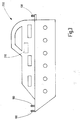
- FIG Figure 1 shows a navigation light 100 for use on a watercraft 200 (for the sake of clarity in FIG Figure 1 not shown).
- the navigation light 100 has four light modules 10, 11, 12, 13 arranged one above the other. Each of these light modules 10, 11, 12, 13 has LEDs Illuminant 14 on.
- the light modules 10, 11, 12, 13 are circumferentially enclosed by a transparent jacket 22 designed as a glass cylinder.
- each case two of the light modules 10, 11, 12, 13 are designed to be identical to one another.
- the individual light modules 10, 11, 12, 13 are connected to one another via corresponding connecting means 21 for producing a detachable connection between the light modules 10, 11, 12, 13.
- the connecting means 21 can be designed as screw connections, for example.
- a base 15 with a bayonet lock is arranged below the base plate of the navigation light 100.
- the bayonet lock is formed by buttons 16 protruding laterally from the base 15.
- the base 15 with bayonet lock is used for mechanical connection or coupling with the deck of the watercraft 200.
- a socket 210 with a lateral longitudinal slot 211 and transverse slot 212 for receiving the buttons 16 forming the bayonet lock on the base 15 is arranged in the deck of the watercraft 200.
- an electrical connection plug 18 is provided at the end of the supply lines 19.
- the electrical connection plug 18 is arranged in the socket 210 and is designed for insertion into the electrical connection socket 17 in the base 15 of the navigation light 100.
- Figure 2 shows the navigation light off Figure 1 as an exploded view without the transparent jacket 22 for the sake of clarity.
- the four light modules 10, 11, 12, 13 to be arranged one above the other have connecting means 21 for producing a detachable connection between the individual light modules 10, 11, 12, 13.
- the connecting means 21 are designed as screw connections.
- the connecting means 21 could also represent plug connections, for example.
- the base plate of the navigation light 100 under which the base 15 is arranged, also has such a connecting means 21.
- the light modules 10, 11, 12, 13 arranged one above the other and connected to one another can thus be exchanged in a simple manner.
- Figure 3 shows a watercraft 200 in the form of a ship with several navigation lights 100 arranged thereon.
- the navigation lights 100 are mechanically connected to the base 15 via the bayonet connection (for the sake of clarity in FIG Figure 3 not shown) of the navigation light 100 is attached to the deck of the watercraft 200.
- the electrical supply or connection of the light modules 10, 11, 12, 13 of the navigation lights 100 takes place via in Figure 3 Supply lines 19, not shown, which are laid centrally from a control center 213 of the watercraft 200.
Landscapes
- Engineering & Computer Science (AREA)
- General Engineering & Computer Science (AREA)
- Physics & Mathematics (AREA)
- Microelectronics & Electronic Packaging (AREA)
- Optics & Photonics (AREA)
- Chemical & Material Sciences (AREA)
- Combustion & Propulsion (AREA)
- Mechanical Engineering (AREA)
- Ocean & Marine Engineering (AREA)
- Non-Portable Lighting Devices Or Systems Thereof (AREA)
- Fastening Of Light Sources Or Lamp Holders (AREA)
- Arrangement Of Elements, Cooling, Sealing, Or The Like Of Lighting Devices (AREA)
Abstract
Description
- Die Erfindung betrifft eine Navigationsleuchte, welche auf einem Wasserfahrzeug anordbar oder angeordnet ist, wobei die Navigationsleuchte mindestens zwei übereinander angeordnete Lichtmodule mit jeweils mehreren LED Leuchtmitteln aufweist.
- Des Weiteren betrifft die Erfindung ein Wasserfahrzeug mit mehreren Navigationsleuchten.
- Auf Wasserfahrzeugen, beispielsweise großen Yachten, werden in der Regel mehrere Navigationsleuchten angeordnet. Die Navigationsleuchten sind üblicherweise als Rundumleuchte und/oder Sektorleuchte ausgebildet. Es ist bekannt, solche Navigationsleuchten über Versorgungsleitungen mit einer Steuerzentrale der Yacht zu verbinden.
- In der
KR 10-2017-0070707 A - In der
DE 10 2011 010 681 A beschreibt eine Vorrichtung zur Erzeugung von Licht zur Befeuerung für Leit- oder Richtfeuer. Das Licht wird dabei über - Leuchtdioden erzeugt. Der elektrische Anschluss wird über eine Steckerverbindung hergestellt.
- Aufgabe der vorliegenden Erfindung ist es, eine Navigationsleuchte mit mehreren übereinander angeordneten LED-basierten Lichtmodulen für den Einsatz auf Wasserfahrzeugen derart flexibel auszugestalten, dass die Navigationsleuchte in einfacher Weise ausgewechselt werden kann.
- Hierfür wird erfindungsgemäß eine Navigationsleuchte, welche auf einem Wasserfahrzeug anordbar oder angeordnet ist, vorgeschlagen, wobei die Navigationsleuchte mindesten zwei übereinander angeordnete Lichtmodule mit mehreren LED Leuchtmitteln aufweist. Die Navigationsleuchte weist ferner einen Sockel mit einem Bajonettverschluss zur mechanischen Verbindung mit einer wasserfahrzeugseitigen Buchse auf.
- Das Wasserfahrzeug kann beispielsweise ein Schiff, Boot, Yacht oder eine schwimmende Plattform sein. Üblicherweise werden auf großen Yachten mehrere Navigationsleuchten verwendet und jeweils über Versorgungsleitungen mit einer Steuerzentrale auf dem Schiff verbunden.
- Die erfindungsgemäße Navigationsleuchte ist in einfacher Weise auf dem Deck des Wasserfahrzeuges zu befestigen und bei Bedarf auszutauschen. Hierfür ist der Sockel mit dem Bajonettverschluss für die mechanische Verbindung beziehungsweise Kopplung ausgebildet und im unteren Bereich der Navigationsleuchte angeordnet. Zur Ausbildung des Bajonettverschlusses sind am Sockel zwei seitlich abstehende Vorsprünge beziehungsweise Knöpfe angeordnet. Es könnten auch mehr als zwei umfänglich verteilt angeordnete und seitlich abstehende Vorsprünge beziehungsweise Knöpfe am Sockel vorgesehen sein.
- Wasserfahrzeugzeitig ist auf dem Deck eine Buchse zur Aufnahme des Sockels der Navigationsleuchte angeordnet. Hierfür weist die Buchse eine Ausnehmung für die Aufnahme des Sockels sowie einen Längs- und einen Querschlitz für die Aufnahme der seitlich vom Sockel abstehenden Vorsprünge beziehungsweise Knöpfe auf. Die Navigationsleuchte kann mit dem Bajonettverschluss am Sockel in die Buchse hineingesetzt werden, indem die seitlich vom Sockel abstehenden Vorsprünge beziehungsweise Knöpfe in den Längsschlitz der Buchse hineingeführt werden. Anschließend werden mittels einer Drehbewegung der Navigationsleuchte die zwei Vorsprünge beziehungsweise Knöpfe in den Querschlitz bis zum Anschlag gedreht. Somit ist eine feste, aber lösbare mechanische Verbindung beziehungsweise Kopplung zwischen Sockel und Buchse und somit der Navigationsleuchte auf dem Deck des Wasserfahrzeuges hergestellt.
- Die mindestens zwei Lichtmodule sind bevorzugterweise als Rundumleuchten oder als Sektorleuchten ausgebildet. Mittels einer Rundumleuchte kann beispielsweise ein Ankerlicht bereitgestellt werden. Mittels einer Sektorleuchte wird beispielsweise ein Dampferlicht bereitgestellt.
- Bevorzugterweise sind die mindestens zwei Lichtmodule im Wesentlichen identisch zueinander, also entweder beide als Rundumleuchten oder beide als Sektorleuchten, ausgebildet. Somit kann eine Redundanz bereitgestellt werden. Zu einem Zeitpunkt wird dann immer nur eines der beiden identisch ausgebildeten Lichtmodule der Navigationsleuchte mit Spannung beziehungsweise Strom versorgt. Wird ein Ausfall eines LED Leuchtmittels in dem Lichtmodul festgestellt, kann mittels geeigneter Steuerung auf das zweite Lichtmodul umgeschaltet werden.
- Des Weiteren ist bevorzugterweise vorgesehen, dass die Navigationsleuchte modular aufgebaut ist und die mindestens zwei Lichtmodule lösbar miteinander verbunden sowie aufeinander gesteckt oder geschraubt sind. Dies ermöglicht nicht nur einen einfachen Austausch der gesamten Navigationsleuchte, sondern auch einzelner Lichtmodule. Beispielsweise kann bei einem Defekt auf das zweite Lichtmodul umgeschaltet werden und das erste Lichtmodul in einfacher Weise und schnell gegen ein neues getauscht werden, ohne dass die gesamte Navigationsleuchte ausgetauscht werden muss.
- Die Navigationsleuchte weist bevorzugterweise einen transparenten Mantel auf, welcher sämtliche Lichtmodule umfänglich umschließt. Der Mantel kann zylinderförmig und beispielsweise als Glaszylinder ausgebildet sein. Besonders bevorzugterweise ist der transparente Mantel derart ausgebildet, dass dieser über die Navigationsleuchte gestülpt werden kann. Damit die einzelnen Lichtmodule für einen eventuellen Austausch gut zugänglich sind, ist der transparente Mantel über eine lösbare Verbindung, beispielsweise eine Steck-oder Schraubverbindung, mit dem Körper der Navigationsleuchte, beispielsweise einer Bodenplatte, verbunden.
- Auch ist bevorzugterweise vorgesehen, dass die Navigationsleuchte mindestens vier übereinander angeordnete Lichtmodule mit jeweils mehreren LED Leuchtmitteln aufweist. Somit weist die Navigationsleuchte bevorzugterweise nicht nur zwei Lichtmodule, sondern mindestens zwei weitere Lichtmodule auf. Ganz besonders bevorzugterweise ist die Navigationsleuchte derart modular ausgebildet, dass alle vier Lichtmodule übereinander angeordnet und miteinander lösbar, beispielsweise über Steck- oder Schraubverbindungen, verbunden sind.
- Zwei der mindestens vier Lichtmodule sind bevorzugterweise als Rundumleuchten und zwei weitere Lichtmodule als Sektorleuchten ausgebildet. Somit sind immer zwei Lichtmodule im Wesentlichen identisch zueinander ausgebildet. Mittels einer derartigen Navigationsleuchte können zwei Funktionen, beispielsweise ein Ankerlicht und ein Dampferlicht bereitgestellt werden, wobei für jede Funktion eine Redundanz durch das doppelte Vorsehen der Lichtmodule bereitgestellt ist.
- Im Sockel der Navigationsleuchte ist bevorzugterweise eine elektrische Anschlussbuchse zur Aufnahme eines elektrischen Anschlusssteckers für eine Stromversorgung der Lichtmodule über Stromversorgungsleitungen angeordnet. Die elektrische Stromversorgung kann beispielsweise von einer wasserfahrzeugseitig angeordneten Steuerzentrale über entsprechende zweiadrige Stromversorgungsleitungen vorgesehen sein.
- Die wasserfahrzeugseitige Buchse zur Aufnahme des Sockels mit Bajonettverschluss dient lediglich der mechanischen Verbindung beziehungsweise Kopplung auf dem Deck des Wasserfahrzeuges. Bevorzugterweise ist für die elektrische Anbindung am Ende der wasserfahrzeugseitig verlegten Stromversorgungsleitungen ein elektrischer Anschlussstecker vorgesehen, welcher in die elektrische Anschlussbuchse im Sockel der Navigationsleuchte gesteckt werden kann. Der elektrische Anschlussstecker kann hierfür beispielsweise in der wasserfahrzeugseitigen Buchse angeordnet sein.
- Des Weiteren ist bevorzugterweise vorgesehen, dass die Navigationsleuchte eine Prüfanordnung aufweist, die eine Erkennung ermöglicht, ob die Navigationsleuchte mit dessen Sockel richtig in die wasserfahrzeugseitige Buchse eingesetzt ist. Mittels der Prüfanordnung kann somit geprüft und erkannt werden, ob der Bajonettverschluss am Sockel und somit die gesamte Navigationsleuchte richtig herum in die wasserfahrzeugseitige Buchse eingesetzt wurde. Ebenfalls kann über die Prüfanordnung geprüft und erkannt werden, ob der Bajonettverschluss nach dem Einsetzen in die wasserfahrzeugseitige Buchse bis zum Anschlag gedreht wurde. Die Prüfanordnung kann über ein geeignetes Erkennungsmittel verfügen, welches das richtige Einsetzen und den Verschluss durch Drehung bis zum Anschlag erkennt und dem Benutzer dies visuell und/oder akustisch anzeigt.
- Bevorzugterweise kann die Prüfanordnung einen oder mehrere Hallsensoren aufweisen oder daraus bestehen. Der Hallsensor kann beispielsweise im Sockel integriert sein. Die Positionierung des Hallsensors innerhalb des Sockels relativ zur Position innerhalb der Buchse kann zur Erkennung genutzt werden.
- Vorzugsweise weist die Navigationsleuchte eine Einrichtung, z.B. elektronische Schaltung, zur Reduzierung der Tragweite auf. Diese Einrichtung ist vorzugsweise derart ausgebildet, dass durch entsprechend kodierte, nicht sichtbare Unterbrechungen in der Stromversorgung, eine Reduzierung der Tragweite erreicht wird. Somit ist die Einrichtung ausgebildet, kodierte und nicht sichtbare Unterbrechungen in der Stromversorgung zu erzeugen. Dies kann insbesondere für militärische Anwendungen sinnvoll sein. Erfindungsgemäß ist ferner ein Wasserfahrzeug mit mehreren vorbeschriebenen Navigationsleuchten vorgesehen. Die Navigationsleuchten sind über eine wasserfahrzeugseitig angeordnete Steuerzentrale mittels entsprechender Stromversorgungsleitungen elektrisch verbunden. Durch den Bajonettverschluss am Sockel einer jeden Navigationsleuchte sind die Navigationsleuchten fest aber lösbar auf dem Deck des Wasserfahrzeuges mechanisch gekoppelt beziehungsweise verbunden.
- Die Erfindung wird im Folgenden anhand bevorzugter Ausführungsformen beispielhaft erläutert.
- Es zeigen schematisch:
- Figur 1:
- eine Navigationsleuchte mit Sockel und Bajonettverschluss;
- Figur 2:
- eine Explosionsdarstellung einer Navigationsleuchte mit Sockel und Bajonettverschluss; und
- Figur 3:
- ein Wasserfahrzeug mit mehreren darauf angeordneten Navigationsleuchten.
-
Figur 1 zeigt eine Navigationsleuchte 100 für den Einsatz auf einem Wasserfahrzeug 200 (der besseren Übersicht halber inFigur 1 nicht dargestellt). Die Navigationsleuchte 100 weist vier übereinander angeordnete Lichtmodule 10, 11, 12, 13 auf. Jedes dieser Lichtmodule 10, 11, 12, 13 weist LED Leuchtmittel 14 auf. Die Lichtmodule 10, 11, 12, 13 sind von einem als Glaszylinder ausgebildetem transparentem Mantel 22 umfänglich umschlossen. - Jeweils zwei der Lichtmodule 10, 11, 12, 13 sind identisch zueinander ausgebildet. Die einzelnen Lichtmodule 10, 11, 12, 13 sind über entsprechende Verbindungsmittel 21 zur Herstellung einer lösbaren Verbindung zwischen den Lichtmodulen 10, 11, 12, 13 miteinander verbunden. Die Verbindungsmittel 21 können beispielsweise als Schraubverbindungen ausgebildet sein.
- Unterhalb der Bodenplatte der Navigationsleuchte 100 ist ein Sockel 15 mit einem Bajonettverschluss angeordnet. Der Bajonettverschluss wird durch seitlich vom Sockel 15 abstehende Knöpfe 16 ausgebildet. Der Sockel 15 mit Bajonettverschluss dient zur mechanischen Verbindung beziehungsweise Kupplung mit dem Deck des Wasserfahrzeuges 200. Hierfür ist im Deck des Wasserfahrzeuges 200 eine Buchse 210 mit seitlichem Längsschlitz 211 und Querschlitz 212 für die Aufnahme der den Bajonettverschluss ausbildenden Knöpfe 16 am Sockel 15 angeordnet.
- Für die elektrische Verbindung ist am Ende der Versorgungsleitungen 19 ein elektrischer Anschlussstecker 18 vorgesehen. Der elektrische Anschlussstecker 18 ist in der Buchse 210 angeordnet und zum Einsetzen in die elektrische Anschlussbuchse 17 im Sockel 15 der Navigationsleuchte 100 ausgebildet.
-
Figur 2 zeigt die Navigationsleuchte ausFigur 1 als Explosionszeichnung der besseren Übersicht halber ohne den transparenten Mantel 22. Die vier übereinander anzuordnenden Lichtmodule 10, 11, 12, 13 weisen Verbindungsmittel 21 zur Herstellung einer lösbaren Verbindung zwischen den einzelnen Lichtmodulen 10, 11, 12, 13 auf. In dem hier dargestellten Beispiel sind die Verbindungsmittel 21 als Schraubverbindungen ausgebildet. Alternativerweise könnten die Verbindungsmittel 21 zum Beispiel auch Steckverbindungen darstellen. - Auch die Bodenplatte der Navigationsleuchte 100, unter welcher der Sockel 15 angeordnet ist, weist ein solches Verbindungsmittel 21 auf. Die derart übereinander angeordneten und miteinander verbundenen Lichtmodule 10, 11, 12, 13 können somit in einfacher Weise ausgetauscht werden.
-
Figur 3 zeigt ein Wasserfahrzeug 200 in Form eines Schiffes mit mehreren darauf angeordneten Navigationsleuchten 100. Die Navigationsleuchten 100 sind mechanisch über die Bajonettverbindung am Sockel 15 (der besseren Übersicht halber inFigur 3 nicht dargestellt) der Navigationsleuchte 100 auf dem Deck des Wasserfahrzeuges 200 befestigt. Die elektrische Versorgung beziehungsweise Verbindung der Lichtmodule 10, 11, 12, 13 der Navigationsleuchten 100 erfolgt über inFigur 3 nicht dargestellte Versorgungsleitungen 19, welche zentral von einer Steuerzentrale 213 des Wasserfahrzeuges 200 aus verlegt sind. -
- 100
- Navigationsleuchte
- 200
- Wasserfahrzeug
- 10
- Erstes Lichtmodul
- 11
- Zweites Lichtmodul
- 12
- Drittes Lichtmodul
- 13
- Viertes Lichtmodul
- 14
- LED Leuchtmittel
- 15
- Sockel
- 16
- Knopf
- 17
- Elektrische Anschlussbuchse
- 18
- Elektrischer Anschlussstecker
- 19
- Stromversorgungsleitung
- 20
- Prüfanordnung
- 21
- Verbindungsmittel
- 22
- Mantel
- 210
- Buchse
- 211
- Längsschlitz
- 212
- Querschlitz
- 213
- Steuerzentrale
Claims (10)
- Navigationsleuchte (100) welche auf einem Wasserfahrzeug (200) anordbar oder angeordnet ist, wobei die Navigationsleuchte (100) mindestens zwei übereinander angeordnete Lichtmodule (10, 11, 12, 13) mit jeweils mehreren LED Leuchtmitteln (14) aufweist,
dadurch gekennzeichnet,
dass die Navigationsleuchte (100) einen Sockel (15) mit einem Bajonettverschluss zur mechanischen Verbindung mit einer Wasserfahrzeugseitgen Buchse (21) aufweist. - Navigationsleuchte (100) gemäß Anspruch 1,
dadurch gekennzeichnet,
dass die mindestens zwei Lichtmodule (10, 11, 12, 13) als Rundumleuchten oder als Sektorleuchten ausgebildet sind. - Navigationsleuchte (100) gemäß Anspruch 1 oder 2,
dadurch gekennzeichnet,
dass die Navigationsleuchte (100) modular aufgebaut ist und die mindestens zwei Lichtmodule (10, 11, 12, 13) lösbar miteinander verbunden und aufeinander gesteckt oder geschraubt sind. - Navigationsleuchte (100) gemäß einem der vorhergehenden Ansprüche,
dadurch gekennzeichnet,
dass die Navigationsleuchte (100) einen transparenten Mantel (22) aufweist, welcher sämtliche Lichtmodule (10, 11, 12, 13) umfänglich umschließt. - Navigationsleuchte (100) gemäß einem der vorhergehenden Ansprüche,
dadurch gekennzeichnet,
dass die Navigationsleuchte (100) mindestens vier übereinander angeordnete Lichtmodule (10, 11, 12, 13) mit jeweils mehreren LED Leuchtmitteln (14) aufweist. - Navigationsleuchte (100) gemäß Anspruch 5,
dadurch gekennzeichnet,
dass zwei der mindestens vier Lichtmodule (10, 11, 12, 13) als Rundumleuchten und zwei als Sektorleuchten ausgebildet sind. - Navigationsleuchte (100) gemäß einem der vorhergehenden Ansprüche,
dadurch gekennzeichnet,
dass im Sockel (15) eine elektrische Anschlussbuchse (17) zur Aufnahme eines elektrischen Anschlusssteckers (18) für eine Stromversorgung der Lichtmodule (10, 11, 12, 13) über Stromversorgungsleitungen (19) angeordnet ist. - Navigationsleuchte (100) gemäß einem der vorhergehenden Ansprüche,
dadurch gekennzeichnet,
dass die Navigationsleuchte (100) eine Prüfanordnung (20) zur Erkennung, ob die Navigationsleuchte (100) mit dessen Sockel (15) richtig in die Wasserfahrzeugseitige Buchse (210) eingesetzt ist, aufweist. - Navigationsleuchte (100) gemäß Anspruch 8,
dadurch gekennzeichnet,
dass die Prüfanordnung (20) einen Hallsensor aufweist. - Wasserfahrzeug (300) mit mehreren Navigationsleuchten (200) gemäß
der vorhergehenden Ansprüche.
Applications Claiming Priority (1)
| Application Number | Priority Date | Filing Date | Title |
|---|---|---|---|
| DE202019106441.2U DE202019106441U1 (de) | 2019-11-19 | 2019-11-19 | Navigationsleuchte mit mehreren Lichtmodulen und Sockel mit Bajonettverschloss |
Publications (2)
| Publication Number | Publication Date |
|---|---|
| EP3825224A2 true EP3825224A2 (de) | 2021-05-26 |
| EP3825224A3 EP3825224A3 (de) | 2021-06-02 |
Family
ID=69885890
Family Applications (1)
| Application Number | Title | Priority Date | Filing Date |
|---|---|---|---|
| EP20208732.6A Withdrawn EP3825224A3 (de) | 2019-11-19 | 2020-11-19 | Navigationsleuchte mit mehreren lichtmodulen und sockel mit bajonettverschloss |
Country Status (2)
| Country | Link |
|---|---|
| EP (1) | EP3825224A3 (de) |
| DE (1) | DE202019106441U1 (de) |
Citations (2)
| Publication number | Priority date | Publication date | Assignee | Title |
|---|---|---|---|---|
| DE102011010681A1 (de) | 2011-02-08 | 2012-08-09 | Fachstelle der Wasser- und Schiffahrtsverwaltung für Verkehrstechniken | Vorrichtung zur Erzeugung von Licht zur Befeuerung |
| KR20170070707A (ko) | 2015-12-14 | 2017-06-22 | 재단법인한국조선해양기자재연구원 | 선박용 엘이디 항해등 |
Family Cites Families (4)
| Publication number | Priority date | Publication date | Assignee | Title |
|---|---|---|---|---|
| DE102014118066A1 (de) * | 2014-12-08 | 2016-06-09 | Endress + Hauser Conducta Gesellschaft für Mess- und Regeltechnik mbH + Co. KG | Verfahren und Steckverbindung zur Information einer Prozessleitzentrale über ein Abtrennen eines Sensors von einem Messumformer |
| DE202015009051U1 (de) * | 2015-01-12 | 2016-08-03 | Auer Signal Gmbh | Signalvorrichtung |
| JP2018098092A (ja) * | 2016-12-15 | 2018-06-21 | オムロン株式会社 | 航海灯制御システム及び照明灯制御システム |
| US10609783B2 (en) * | 2017-11-20 | 2020-03-31 | David J Horst | Self-monitoring marine navigation light |
-
2019
- 2019-11-19 DE DE202019106441.2U patent/DE202019106441U1/de active Active
-
2020
- 2020-11-19 EP EP20208732.6A patent/EP3825224A3/de not_active Withdrawn
Patent Citations (2)
| Publication number | Priority date | Publication date | Assignee | Title |
|---|---|---|---|---|
| DE102011010681A1 (de) | 2011-02-08 | 2012-08-09 | Fachstelle der Wasser- und Schiffahrtsverwaltung für Verkehrstechniken | Vorrichtung zur Erzeugung von Licht zur Befeuerung |
| KR20170070707A (ko) | 2015-12-14 | 2017-06-22 | 재단법인한국조선해양기자재연구원 | 선박용 엘이디 항해등 |
Also Published As
| Publication number | Publication date |
|---|---|
| DE202019106441U1 (de) | 2020-02-27 |
| EP3825224A3 (de) | 2021-06-02 |
Similar Documents
| Publication | Publication Date | Title |
|---|---|---|
| DE10012734C1 (de) | Illuminationsbausatz für Beleuchtungs-, Anzeige- oder Hinweiszwecke sowie Steckverbinder für einen solchen Illuminationsbausatz | |
| EP1405377A2 (de) | Led-modul für beleuchtungsvorrichtungen | |
| DE102008005823A1 (de) | Anschlusselement zur elektrischen Anbindung einer LED | |
| EP1347233B1 (de) | Signalsäule | |
| DE102012023190B4 (de) | Signalsäule | |
| EP0942474B1 (de) | Leuchtdiode | |
| EP3825224A2 (de) | Navigationsleuchte mit mehreren lichtmodulen und sockel mit bajonettverschloss | |
| DE102009054510A1 (de) | Leuchtvorrichtung und Stromschienenadapter zur Verwendung mit der Leuchtvorrichtung | |
| EP2150749B1 (de) | Beleuchtungsvorrichtung mit einer an einer oberfläche eines objekts anbringbaren schienenvorrichtung | |
| DE202018100238U1 (de) | Modular erweiterbare und formveränderliche Leuchte | |
| DE102005009588A1 (de) | Messgerät | |
| EP2815170B1 (de) | Leuchtelement mit einem kodierelement | |
| DE102015118192A1 (de) | LED Panel | |
| DE102009047358A1 (de) | Brandmelder- und/oder -warnvorrichtung | |
| DE10123006B4 (de) | Leuchtvorrichtung zur Erzeugung einer aktiv nachleuchtenden Signalfläche | |
| EP1480246A2 (de) | Elektrische Lampe mit drehbarem Sockel | |
| AT12652U1 (de) | Vorrichtung zum befestigen und kontaktieren eines leuchtmittels und/oder eines leuchtmoduls, sowie leuchte | |
| EP3825606A1 (de) | Navigationsleuchte mit optischer überwachung von led leuchtmitteln | |
| EP0432284B1 (de) | Hängetaster zum Steuern von Hebezeugen und/oder Krananlagen | |
| DE102022124494A1 (de) | Geräteanschlusssteckverbinder mit Leuchtanzeige | |
| DE102010025084B4 (de) | Lampenfassung und Lampensockel sowie Anordnung derselben | |
| DE202020101397U1 (de) | Leuchte | |
| EP2940373B1 (de) | Erstausfallsichere Operationsleuchte | |
| EP2149010B1 (de) | Beleuchtungsvorrichtung und adapter zum anbringen einer lampe | |
| DE10247176A1 (de) | Elektrische Weihnachtsbaumbeleuchtung |
Legal Events
| Date | Code | Title | Description |
|---|---|---|---|
| PUAI | Public reference made under article 153(3) epc to a published international application that has entered the european phase |
Free format text: ORIGINAL CODE: 0009012 |
|
| STAA | Information on the status of an ep patent application or granted ep patent |
Free format text: STATUS: THE APPLICATION HAS BEEN PUBLISHED |
|
| PUAL | Search report despatched |
Free format text: ORIGINAL CODE: 0009013 |
|
| AK | Designated contracting states |
Kind code of ref document: A2 Designated state(s): AL AT BE BG CH CY CZ DE DK EE ES FI FR GB GR HR HU IE IS IT LI LT LU LV MC MK MT NL NO PL PT RO RS SE SI SK SM TR |
|
| AK | Designated contracting states |
Kind code of ref document: A3 Designated state(s): AL AT BE BG CH CY CZ DE DK EE ES FI FR GB GR HR HU IE IS IT LI LT LU LV MC MK MT NL NO PL PT RO RS SE SI SK SM TR |
|
| RIC1 | Information provided on ipc code assigned before grant |
Ipc: B63B 45/04 20060101AFI20210423BHEP Ipc: F21K 9/235 20160101ALI20210423BHEP Ipc: F21S 2/00 20160101ALI20210423BHEP Ipc: F21V 21/005 20060101ALI20210423BHEP Ipc: H01R 33/46 20060101ALI20210423BHEP Ipc: F21V 23/06 20060101ALN20210423BHEP Ipc: F21V 31/00 20060101ALN20210423BHEP Ipc: F21W 107/20 20180101ALN20210423BHEP Ipc: F21W 111/00 20060101ALN20210423BHEP Ipc: F21Y 115/10 20160101ALN20210423BHEP Ipc: H01R 13/66 20060101ALN20210423BHEP Ipc: H01R 33/945 20060101ALN20210423BHEP |
|
| STAA | Information on the status of an ep patent application or granted ep patent |
Free format text: STATUS: REQUEST FOR EXAMINATION WAS MADE |
|
| 17P | Request for examination filed |
Effective date: 20211124 |
|
| RBV | Designated contracting states (corrected) |
Designated state(s): AL AT BE BG CH CY CZ DE DK EE ES FI FR GB GR HR HU IE IS IT LI LT LU LV MC MK MT NL NO PL PT RO RS SE SI SK SM TR |
|
| STAA | Information on the status of an ep patent application or granted ep patent |
Free format text: STATUS: EXAMINATION IS IN PROGRESS |
|
| 17Q | First examination report despatched |
Effective date: 20220401 |
|
| STAA | Information on the status of an ep patent application or granted ep patent |
Free format text: STATUS: THE APPLICATION IS DEEMED TO BE WITHDRAWN |
|
| 18D | Application deemed to be withdrawn |
Effective date: 20221012 |