EP3824969A1 - Laufband - Google Patents
Laufband Download PDFInfo
- Publication number
- EP3824969A1 EP3824969A1 EP20151918.8A EP20151918A EP3824969A1 EP 3824969 A1 EP3824969 A1 EP 3824969A1 EP 20151918 A EP20151918 A EP 20151918A EP 3824969 A1 EP3824969 A1 EP 3824969A1
- Authority
- EP
- European Patent Office
- Prior art keywords
- treadmill
- frame
- handle
- pet
- base
- Prior art date
- Legal status (The legal status is an assumption and is not a legal conclusion. Google has not performed a legal analysis and makes no representation as to the accuracy of the status listed.)
- Granted
Links
- 239000003205 fragrance Substances 0.000 claims abstract description 64
- 238000003860 storage Methods 0.000 claims description 23
- 230000003247 decreasing effect Effects 0.000 claims description 16
- 230000008878 coupling Effects 0.000 claims description 7
- 238000010168 coupling process Methods 0.000 claims description 7
- 238000005859 coupling reaction Methods 0.000 claims description 7
- 230000008859 change Effects 0.000 claims description 6
- 239000000725 suspension Substances 0.000 abstract description 13
- 230000035943 smell Effects 0.000 abstract description 8
- 239000003570 air Substances 0.000 description 53
- 238000000034 method Methods 0.000 description 37
- 230000008569 process Effects 0.000 description 27
- 238000004891 communication Methods 0.000 description 17
- 230000005021 gait Effects 0.000 description 14
- 239000010410 layer Substances 0.000 description 14
- 230000001699 photocatalysis Effects 0.000 description 14
- 230000001954 sterilising effect Effects 0.000 description 11
- 241000282472 Canis lupus familiaris Species 0.000 description 10
- 241001465754 Metazoa Species 0.000 description 9
- 238000001816 cooling Methods 0.000 description 8
- 150000002500 ions Chemical class 0.000 description 6
- 239000011941 photocatalyst Substances 0.000 description 6
- 239000000463 material Substances 0.000 description 5
- 239000004033 plastic Substances 0.000 description 5
- 239000012080 ambient air Substances 0.000 description 4
- 239000003344 environmental pollutant Substances 0.000 description 4
- 235000019645 odor Nutrition 0.000 description 4
- 231100000719 pollutant Toxicity 0.000 description 4
- 230000004044 response Effects 0.000 description 4
- 241000894006 Bacteria Species 0.000 description 3
- 241000282412 Homo Species 0.000 description 3
- 235000013305 food Nutrition 0.000 description 3
- 238000010438 heat treatment Methods 0.000 description 3
- 238000004519 manufacturing process Methods 0.000 description 3
- 238000005259 measurement Methods 0.000 description 3
- 230000007246 mechanism Effects 0.000 description 3
- 229910052751 metal Inorganic materials 0.000 description 3
- 239000002184 metal Substances 0.000 description 3
- 230000004048 modification Effects 0.000 description 3
- 238000012986 modification Methods 0.000 description 3
- 230000005855 radiation Effects 0.000 description 3
- 239000004576 sand Substances 0.000 description 3
- XLYOFNOQVPJJNP-UHFFFAOYSA-N water Substances O XLYOFNOQVPJJNP-UHFFFAOYSA-N 0.000 description 3
- 208000019901 Anxiety disease Diseases 0.000 description 2
- 230000036506 anxiety Effects 0.000 description 2
- 239000003086 colorant Substances 0.000 description 2
- 230000017525 heat dissipation Effects 0.000 description 2
- 230000010354 integration Effects 0.000 description 2
- 230000009191 jumping Effects 0.000 description 2
- 239000007788 liquid Substances 0.000 description 2
- 235000013372 meat Nutrition 0.000 description 2
- 244000005700 microbiome Species 0.000 description 2
- 230000007935 neutral effect Effects 0.000 description 2
- 230000003068 static effect Effects 0.000 description 2
- 241000282326 Felis catus Species 0.000 description 1
- 229920000544 Gore-Tex Polymers 0.000 description 1
- 206010070670 Limb asymmetry Diseases 0.000 description 1
- 241001417527 Pempheridae Species 0.000 description 1
- GWEVSGVZZGPLCZ-UHFFFAOYSA-N Titan oxide Chemical compound O=[Ti]=O GWEVSGVZZGPLCZ-UHFFFAOYSA-N 0.000 description 1
- RTAQQCXQSZGOHL-UHFFFAOYSA-N Titanium Chemical compound [Ti] RTAQQCXQSZGOHL-UHFFFAOYSA-N 0.000 description 1
- 208000027418 Wounds and injury Diseases 0.000 description 1
- 230000002745 absorbent Effects 0.000 description 1
- 239000002250 absorbent Substances 0.000 description 1
- 230000001154 acute effect Effects 0.000 description 1
- 230000000712 assembly Effects 0.000 description 1
- 238000000429 assembly Methods 0.000 description 1
- 230000004888 barrier function Effects 0.000 description 1
- 238000007664 blowing Methods 0.000 description 1
- 230000001914 calming effect Effects 0.000 description 1
- 238000004140 cleaning Methods 0.000 description 1
- 230000006378 damage Effects 0.000 description 1
- 230000001877 deodorizing effect Effects 0.000 description 1
- 238000001514 detection method Methods 0.000 description 1
- 238000010586 diagram Methods 0.000 description 1
- 230000000694 effects Effects 0.000 description 1
- 239000013013 elastic material Substances 0.000 description 1
- 230000005611 electricity Effects 0.000 description 1
- 239000004744 fabric Substances 0.000 description 1
- 238000002347 injection Methods 0.000 description 1
- 239000007924 injection Substances 0.000 description 1
- 208000014674 injury Diseases 0.000 description 1
- 230000000670 limiting effect Effects 0.000 description 1
- 239000004973 liquid crystal related substance Substances 0.000 description 1
- 230000004630 mental health Effects 0.000 description 1
- RSMUVYRMZCOLBH-UHFFFAOYSA-N metsulfuron methyl Chemical compound COC(=O)C1=CC=CC=C1S(=O)(=O)NC(=O)NC1=NC(C)=NC(OC)=N1 RSMUVYRMZCOLBH-UHFFFAOYSA-N 0.000 description 1
- 230000001590 oxidative effect Effects 0.000 description 1
- 230000036961 partial effect Effects 0.000 description 1
- 239000002245 particle Substances 0.000 description 1
- 238000000554 physical therapy Methods 0.000 description 1
- 150000003071 polychlorinated biphenyls Chemical class 0.000 description 1
- 238000003825 pressing Methods 0.000 description 1
- 239000011241 protective layer Substances 0.000 description 1
- 230000002829 reductive effect Effects 0.000 description 1
- 238000005096 rolling process Methods 0.000 description 1
- 238000004088 simulation Methods 0.000 description 1
- 239000000779 smoke Substances 0.000 description 1
- 239000007787 solid Substances 0.000 description 1
- 238000001228 spectrum Methods 0.000 description 1
- 229910001220 stainless steel Inorganic materials 0.000 description 1
- 239000010935 stainless steel Substances 0.000 description 1
- 238000004659 sterilization and disinfection Methods 0.000 description 1
- 230000000638 stimulation Effects 0.000 description 1
- 210000004243 sweat Anatomy 0.000 description 1
- 239000010936 titanium Substances 0.000 description 1
- 229960005196 titanium dioxide Drugs 0.000 description 1
- OGIDPMRJRNCKJF-UHFFFAOYSA-N titanium oxide Inorganic materials [Ti]=O OGIDPMRJRNCKJF-UHFFFAOYSA-N 0.000 description 1
- 210000001364 upper extremity Anatomy 0.000 description 1
- 230000008016 vaporization Effects 0.000 description 1
- 230000000007 visual effect Effects 0.000 description 1
Images


Classifications
-
- A—HUMAN NECESSITIES
- A63—SPORTS; GAMES; AMUSEMENTS
- A63B—APPARATUS FOR PHYSICAL TRAINING, GYMNASTICS, SWIMMING, CLIMBING, OR FENCING; BALL GAMES; TRAINING EQUIPMENT
- A63B22/00—Exercising apparatus specially adapted for conditioning the cardio-vascular system, for training agility or co-ordination of movements
- A63B22/02—Exercising apparatus specially adapted for conditioning the cardio-vascular system, for training agility or co-ordination of movements with movable endless bands, e.g. treadmills
-
- A—HUMAN NECESSITIES
- A01—AGRICULTURE; FORESTRY; ANIMAL HUSBANDRY; HUNTING; TRAPPING; FISHING
- A01K—ANIMAL HUSBANDRY; CARE OF BIRDS, FISHES, INSECTS; FISHING; REARING OR BREEDING ANIMALS, NOT OTHERWISE PROVIDED FOR; NEW BREEDS OF ANIMALS
- A01K15/00—Devices for taming animals, e.g. nose-rings or hobbles; Devices for overturning animals in general; Training or exercising equipment; Covering boxes
- A01K15/02—Training or exercising equipment, e.g. mazes or labyrinths for animals ; Electric shock devices ; Toys specially adapted for animals
- A01K15/027—Exercising equipment, e.g. tread mills, carousels
-
- A—HUMAN NECESSITIES
- A63—SPORTS; GAMES; AMUSEMENTS
- A63B—APPARATUS FOR PHYSICAL TRAINING, GYMNASTICS, SWIMMING, CLIMBING, OR FENCING; BALL GAMES; TRAINING EQUIPMENT
- A63B22/00—Exercising apparatus specially adapted for conditioning the cardio-vascular system, for training agility or co-ordination of movements
- A63B22/02—Exercising apparatus specially adapted for conditioning the cardio-vascular system, for training agility or co-ordination of movements with movable endless bands, e.g. treadmills
- A63B22/0235—Exercising apparatus specially adapted for conditioning the cardio-vascular system, for training agility or co-ordination of movements with movable endless bands, e.g. treadmills driven by a motor
-
- A—HUMAN NECESSITIES
- A63—SPORTS; GAMES; AMUSEMENTS
- A63B—APPARATUS FOR PHYSICAL TRAINING, GYMNASTICS, SWIMMING, CLIMBING, OR FENCING; BALL GAMES; TRAINING EQUIPMENT
- A63B24/00—Electric or electronic controls for exercising apparatus of preceding groups; Controlling or monitoring of exercises, sportive games, training or athletic performances
- A63B24/0087—Electric or electronic controls for exercising apparatus of groups A63B21/00 - A63B23/00, e.g. controlling load
-
- A—HUMAN NECESSITIES
- A63—SPORTS; GAMES; AMUSEMENTS
- A63B—APPARATUS FOR PHYSICAL TRAINING, GYMNASTICS, SWIMMING, CLIMBING, OR FENCING; BALL GAMES; TRAINING EQUIPMENT
- A63B71/00—Games or sports accessories not covered in groups A63B1/00 - A63B69/00
- A63B71/06—Indicating or scoring devices for games or players, or for other sports activities
- A63B71/0619—Displays, user interfaces and indicating devices, specially adapted for sport equipment, e.g. display mounted on treadmills
- A63B71/0622—Visual, audio or audio-visual systems for entertaining, instructing or motivating the user
- A63B2071/0625—Emitting sound, noise or music
-
- A—HUMAN NECESSITIES
- A63—SPORTS; GAMES; AMUSEMENTS
- A63B—APPARATUS FOR PHYSICAL TRAINING, GYMNASTICS, SWIMMING, CLIMBING, OR FENCING; BALL GAMES; TRAINING EQUIPMENT
- A63B71/00—Games or sports accessories not covered in groups A63B1/00 - A63B69/00
- A63B71/06—Indicating or scoring devices for games or players, or for other sports activities
- A63B71/0619—Displays, user interfaces and indicating devices, specially adapted for sport equipment, e.g. display mounted on treadmills
- A63B71/0622—Visual, audio or audio-visual systems for entertaining, instructing or motivating the user
- A63B2071/0638—Displaying moving images of recorded environment, e.g. virtual environment
- A63B2071/0644—Displaying moving images of recorded environment, e.g. virtual environment with display speed of moving landscape controlled by the user's performance
-
- A—HUMAN NECESSITIES
- A63—SPORTS; GAMES; AMUSEMENTS
- A63B—APPARATUS FOR PHYSICAL TRAINING, GYMNASTICS, SWIMMING, CLIMBING, OR FENCING; BALL GAMES; TRAINING EQUIPMENT
- A63B22/00—Exercising apparatus specially adapted for conditioning the cardio-vascular system, for training agility or co-ordination of movements
- A63B22/02—Exercising apparatus specially adapted for conditioning the cardio-vascular system, for training agility or co-ordination of movements with movable endless bands, e.g. treadmills
- A63B22/0235—Exercising apparatus specially adapted for conditioning the cardio-vascular system, for training agility or co-ordination of movements with movable endless bands, e.g. treadmills driven by a motor
- A63B22/0242—Exercising apparatus specially adapted for conditioning the cardio-vascular system, for training agility or co-ordination of movements with movable endless bands, e.g. treadmills driven by a motor with speed variation
-
- A—HUMAN NECESSITIES
- A63—SPORTS; GAMES; AMUSEMENTS
- A63B—APPARATUS FOR PHYSICAL TRAINING, GYMNASTICS, SWIMMING, CLIMBING, OR FENCING; BALL GAMES; TRAINING EQUIPMENT
- A63B22/00—Exercising apparatus specially adapted for conditioning the cardio-vascular system, for training agility or co-ordination of movements
- A63B22/02—Exercising apparatus specially adapted for conditioning the cardio-vascular system, for training agility or co-ordination of movements with movable endless bands, e.g. treadmills
- A63B22/0285—Physical characteristics of the belt, e.g. material, surface, indicia
-
- A—HUMAN NECESSITIES
- A63—SPORTS; GAMES; AMUSEMENTS
- A63B—APPARATUS FOR PHYSICAL TRAINING, GYMNASTICS, SWIMMING, CLIMBING, OR FENCING; BALL GAMES; TRAINING EQUIPMENT
- A63B22/00—Exercising apparatus specially adapted for conditioning the cardio-vascular system, for training agility or co-ordination of movements
- A63B22/02—Exercising apparatus specially adapted for conditioning the cardio-vascular system, for training agility or co-ordination of movements with movable endless bands, e.g. treadmills
- A63B22/0292—Exercising apparatus specially adapted for conditioning the cardio-vascular system, for training agility or co-ordination of movements with movable endless bands, e.g. treadmills separate for each leg, e.g. dual deck
-
- A—HUMAN NECESSITIES
- A63—SPORTS; GAMES; AMUSEMENTS
- A63B—APPARATUS FOR PHYSICAL TRAINING, GYMNASTICS, SWIMMING, CLIMBING, OR FENCING; BALL GAMES; TRAINING EQUIPMENT
- A63B2208/00—Characteristics or parameters related to the user or player
- A63B2208/14—Characteristics or parameters related to the user or player specially adapted for animals
-
- A—HUMAN NECESSITIES
- A63—SPORTS; GAMES; AMUSEMENTS
- A63B—APPARATUS FOR PHYSICAL TRAINING, GYMNASTICS, SWIMMING, CLIMBING, OR FENCING; BALL GAMES; TRAINING EQUIPMENT
- A63B2210/00—Space saving
- A63B2210/50—Size reducing arrangements for stowing or transport
-
- A—HUMAN NECESSITIES
- A63—SPORTS; GAMES; AMUSEMENTS
- A63B—APPARATUS FOR PHYSICAL TRAINING, GYMNASTICS, SWIMMING, CLIMBING, OR FENCING; BALL GAMES; TRAINING EQUIPMENT
- A63B2220/00—Measuring of physical parameters relating to sporting activity
- A63B2220/10—Positions
- A63B2220/12—Absolute positions, e.g. by using GPS
-
- A—HUMAN NECESSITIES
- A63—SPORTS; GAMES; AMUSEMENTS
- A63B—APPARATUS FOR PHYSICAL TRAINING, GYMNASTICS, SWIMMING, CLIMBING, OR FENCING; BALL GAMES; TRAINING EQUIPMENT
- A63B2220/00—Measuring of physical parameters relating to sporting activity
- A63B2220/10—Positions
- A63B2220/13—Relative positions
-
- A—HUMAN NECESSITIES
- A63—SPORTS; GAMES; AMUSEMENTS
- A63B—APPARATUS FOR PHYSICAL TRAINING, GYMNASTICS, SWIMMING, CLIMBING, OR FENCING; BALL GAMES; TRAINING EQUIPMENT
- A63B2220/00—Measuring of physical parameters relating to sporting activity
- A63B2220/18—Inclination, slope or curvature
-
- A—HUMAN NECESSITIES
- A63—SPORTS; GAMES; AMUSEMENTS
- A63B—APPARATUS FOR PHYSICAL TRAINING, GYMNASTICS, SWIMMING, CLIMBING, OR FENCING; BALL GAMES; TRAINING EQUIPMENT
- A63B2220/00—Measuring of physical parameters relating to sporting activity
- A63B2220/20—Distances or displacements
-
- A—HUMAN NECESSITIES
- A63—SPORTS; GAMES; AMUSEMENTS
- A63B—APPARATUS FOR PHYSICAL TRAINING, GYMNASTICS, SWIMMING, CLIMBING, OR FENCING; BALL GAMES; TRAINING EQUIPMENT
- A63B2220/00—Measuring of physical parameters relating to sporting activity
- A63B2220/20—Distances or displacements
- A63B2220/22—Stride length
-
- A—HUMAN NECESSITIES
- A63—SPORTS; GAMES; AMUSEMENTS
- A63B—APPARATUS FOR PHYSICAL TRAINING, GYMNASTICS, SWIMMING, CLIMBING, OR FENCING; BALL GAMES; TRAINING EQUIPMENT
- A63B2220/00—Measuring of physical parameters relating to sporting activity
- A63B2220/30—Speed
- A63B2220/31—Relative speed
-
- A—HUMAN NECESSITIES
- A63—SPORTS; GAMES; AMUSEMENTS
- A63B—APPARATUS FOR PHYSICAL TRAINING, GYMNASTICS, SWIMMING, CLIMBING, OR FENCING; BALL GAMES; TRAINING EQUIPMENT
- A63B2220/00—Measuring of physical parameters relating to sporting activity
- A63B2220/62—Time or time measurement used for time reference, time stamp, master time or clock signal
-
- A—HUMAN NECESSITIES
- A63—SPORTS; GAMES; AMUSEMENTS
- A63B—APPARATUS FOR PHYSICAL TRAINING, GYMNASTICS, SWIMMING, CLIMBING, OR FENCING; BALL GAMES; TRAINING EQUIPMENT
- A63B2220/00—Measuring of physical parameters relating to sporting activity
- A63B2220/70—Measuring or simulating ambient conditions, e.g. weather, terrain or surface conditions
- A63B2220/76—Wind conditions
-
- A—HUMAN NECESSITIES
- A63—SPORTS; GAMES; AMUSEMENTS
- A63B—APPARATUS FOR PHYSICAL TRAINING, GYMNASTICS, SWIMMING, CLIMBING, OR FENCING; BALL GAMES; TRAINING EQUIPMENT
- A63B2220/00—Measuring of physical parameters relating to sporting activity
- A63B2220/70—Measuring or simulating ambient conditions, e.g. weather, terrain or surface conditions
- A63B2220/78—Surface covering conditions, e.g. of a road surface
-
- A—HUMAN NECESSITIES
- A63—SPORTS; GAMES; AMUSEMENTS
- A63B—APPARATUS FOR PHYSICAL TRAINING, GYMNASTICS, SWIMMING, CLIMBING, OR FENCING; BALL GAMES; TRAINING EQUIPMENT
- A63B2225/00—Miscellaneous features of sport apparatus, devices or equipment
- A63B2225/09—Adjustable dimensions
-
- A—HUMAN NECESSITIES
- A63—SPORTS; GAMES; AMUSEMENTS
- A63B—APPARATUS FOR PHYSICAL TRAINING, GYMNASTICS, SWIMMING, CLIMBING, OR FENCING; BALL GAMES; TRAINING EQUIPMENT
- A63B2225/00—Miscellaneous features of sport apparatus, devices or equipment
- A63B2225/09—Adjustable dimensions
- A63B2225/096—Adjustable dimensions automatically adjusted according to anthropometric data of the user
-
- A—HUMAN NECESSITIES
- A63—SPORTS; GAMES; AMUSEMENTS
- A63B—APPARATUS FOR PHYSICAL TRAINING, GYMNASTICS, SWIMMING, CLIMBING, OR FENCING; BALL GAMES; TRAINING EQUIPMENT
- A63B2225/00—Miscellaneous features of sport apparatus, devices or equipment
- A63B2225/50—Wireless data transmission, e.g. by radio transmitters or telemetry
-
- A—HUMAN NECESSITIES
- A63—SPORTS; GAMES; AMUSEMENTS
- A63B—APPARATUS FOR PHYSICAL TRAINING, GYMNASTICS, SWIMMING, CLIMBING, OR FENCING; BALL GAMES; TRAINING EQUIPMENT
- A63B2225/00—Miscellaneous features of sport apparatus, devices or equipment
- A63B2225/64—Heated
-
- A—HUMAN NECESSITIES
- A63—SPORTS; GAMES; AMUSEMENTS
- A63B—APPARATUS FOR PHYSICAL TRAINING, GYMNASTICS, SWIMMING, CLIMBING, OR FENCING; BALL GAMES; TRAINING EQUIPMENT
- A63B2225/00—Miscellaneous features of sport apparatus, devices or equipment
- A63B2225/66—Cooled
-
- A—HUMAN NECESSITIES
- A63—SPORTS; GAMES; AMUSEMENTS
- A63B—APPARATUS FOR PHYSICAL TRAINING, GYMNASTICS, SWIMMING, CLIMBING, OR FENCING; BALL GAMES; TRAINING EQUIPMENT
- A63B24/00—Electric or electronic controls for exercising apparatus of preceding groups; Controlling or monitoring of exercises, sportive games, training or athletic performances
- A63B24/0059—Exercising apparatus with reward systems
-
- A—HUMAN NECESSITIES
- A63—SPORTS; GAMES; AMUSEMENTS
- A63B—APPARATUS FOR PHYSICAL TRAINING, GYMNASTICS, SWIMMING, CLIMBING, OR FENCING; BALL GAMES; TRAINING EQUIPMENT
- A63B71/00—Games or sports accessories not covered in groups A63B1/00 - A63B69/00
- A63B71/06—Indicating or scoring devices for games or players, or for other sports activities
- A63B71/0619—Displays, user interfaces and indicating devices, specially adapted for sport equipment, e.g. display mounted on treadmills
- A63B71/0622—Visual, audio or audio-visual systems for entertaining, instructing or motivating the user
Definitions
- a treadmill for animals is disclosed herein.
- the related art does not provide a treadmill having multiple cleaning features, an easily customizable treadmill with swappable belts or stimulation modules, a treadmill designed to simulate a landscape through videos, fragrances, and different belts, or a treadmill designed to accommodate gait of a pet.
- An object of the invention is to provide a treadmill having two belts, one for each leg, that move at different speeds to accommodate a gait of the pet. Gait of the pet may be detected by position sensors provided to sense a distance of right and left legs away from a center of the treadmill.
- An object of the invention is to provide a treadmill that maintains a position of a pet on the treadmill so that the treadmill may be used autonomously.
- a sensor provided above the pet may detect a height and forward-backward position of the pet, while sensors provided in a belt divider may detect a left-right position of the pet.
- speeds of the left and right belts may be adjusted to bring the pet back to the center.
- a forward-backward inclination of the treadmill may be adjusted to push the pet back toward the center.
- speeds of the left and right belts may be adjusted to accommodate any gait detected, and a left-right inclination of the treadmill may be adjusted to push the pet back toward the center.
- a texture of the belts may simulate a texture of the landscape (e.g., an AstroTurf belt or sand-based belt).
- a thermoelectric cooler may cool the pet on the treadmill.
- a pet on the treadmill may not need to be caged in, which may reduce anxiety.
- An object of the present invention is to provide a lightweight and portable treadmill for home use.
- a handle is provided that rotates around the treadmill to provide easy storage. During use, the handle may extend over the belts, and a height may be automatically adjusted based on a sensed height of the pet.
- a stand is provided to support the treadmill in an upright position during storage.
- An attachment module which may include a display, speaker, and treat dispenser, may be easily removed so that the display is not damaged during storage.
- a treadmill for a pet comprising a base, a first roller and a second roller spaced apart from each other and supported in the base, a first belt forming a first closed loop around the first roller and the second roller, and a handle rotatably coupled to a middle portion of the base.
- the handle may be configured to rotate to a first position to cross over the first belt and to a second position adjacent to a side of the base in a storage configuration of the treadmill.
- a sensor may be provided in the handle to detect a pet on the first belt.
- the inner frame may have a stopper flange configured to prevent the sliding frame from may be slid past a predetermined position of the base frame.
- the stopper flange may be formed as a raised edge of the inner frame.
- the stopper flange may have a front and a rear. The front may be configured to stop a movement of the lower side of the sliding frame and the rear may be configured to stop a movement of a remaining portion of the sliding frame.
- a portable treadmill comprising a base, a first roller and a second roller spaced apart from each other and supported in the base, a first belt forming a first loop around the first roller and the second roller, and a handle rotatably coupled to a middle portion of the base.
- the handle may be configured to rotate to a first position to cross over the belt and to a second position adjacent to a side of the base. Either in the first or second position, the base may be lifted using the handle for portability from a first location to a second location.
- a sensor may be provided in a handle top of the handle.
- the sensor may be configured to face the first belt and detect a pet when the handle is in the first position.
- the first prescribed speed may be changed based on a position of the pet sensed by the sensor.
- the base may include an outer frame made of plastic, and the handle may be configured to support a weight of the base.
- a third roller and a fourth roller may be spaced apart from each other and supported in the base.
- a second belt may form a second loop around the third roller and the fourth roller.
- the handle sensor 331 may also sense a position of the pet in a frontward and backward direction, and speeds of the left and right belts 110 and 120 may be adjusted to maintain a safe position of the pet on the treadmill 1.
- the speeds of the left and right belts 110 and 120 may also be controlled according to a pre-set exercise program and may correspond to images on the display 210.
- the speeds of the left and right belts 110 and 120 may be increased or decreased by a same amount in response to a position of the pet sensed by the handle sensor 331.
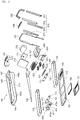
- Discharge holes 154 may be provided in the lower frame 150 of the base 100 to exhaust air from a blower 610 ( FIG. 8 ) inside the treadmill 1. For example, during a cooling operation, hot air may be discharged through the discharge holes 154, while cool air may be blown by the blower 610 through the vents 146. During a heating operation, cool air may be discharged through the discharge holes 154, while hot or warm air may be blown by the blower 610 through the vents 146. A position of the blower 610 may be configured to blow air straight through the vents 146 or to blow air through the vents 146 at a predetermined angle.
- the treadmill 1 may include a fragrance assembly 500 that emits various scents, and the radially bladed fan 610 may disperse scent through the vents 146 to the pet. Scents may be emitted to both lure a pet to the treadmill 1 and stimulate a pet on the treadmill 1 in accordance with a pre-set exercise program and/or images played on the display 210.
- the lower frame 150 of the base 100 may be provided under the left and right belts 110 and 120.
- An upper frame 140 may be coupled to the lower frame 150, and may have an upper opening through which the left and right belts 110 and 120 are exposed.
- the upper frame 140 may have a front frame or cover 141 provided at the front end of the base 100 to cover the fragrance assembly 500 and the blower 610 described later with reference to Figures 23-27 .
- the upper frame 140 may further include a back frame or cover 144 provided at the back end of the base 100, and a pair of side walls or side frames 145 extending between the front and back frames 141 and 144.
- the left and right belts 110 and 120 may be exposed between the side frames 145 and the front and back frames 141 and 144.
- the upper and lower frames 140 and 150 may be made of a plastic so that the treadmill 1 is lightweight, portable, and easy to manufacture.
- the side frames 145 may be bonded or welded to the front and back frames 144 and 141 to form the upper frame 140.
- the upper frame 140 may be pressed-fit or snap-fitted into the lower frame 150.
- the upper frame 140 may be secured to the lower frame 150 via magnetic coupling, adhesion, locking or latching, etc.
- the base 100 and left and right belts 110 and 120 may be configured to support a small to medium sized dog (e.g., 10 kg or 20 lbs or less), but embodiments disclosed herein are not limited thereto.
- the front rollers 112 and 122 may rotate around and be supported by a front shaft 125 supporting the front rollers 112 and 122, and the back rollers 111 and 121 may rotate around and be supported by a back shaft 115.
- the front shaft 125 may extend between and couple to a front pair of roller frames 142b, and the back shaft 115 may extend between and couple to a back pair of roller frames 142a.
- the front and back roller frames 142b and 142a may extend downward from the side frames 145.
- the front and back shafts 125 and 115 may remain fixed, while the left rollers 111 and 112 may rotate at a different speed than the right rollers 121 and 122.
- the front left and right rollers 112 and 122 may not be coupled to each other to facilitate independent rotation and separate left and right speeds, and the back left and right rollers 111 and 121 may similarly not be coupled to each other to facilitate independent rotation and separate left and right speeds.
- a right motor 123 may rotate the front right belt 122 around the front shaft 125 and a left motor 113 may rotate the back left belt 111 around the back shaft 115.
- the front and back shafts 125 and 115 may remain fixed and may not rotate, and the motors 123 and 113 may only rotate the rollers 122 and 111 surrounding the fixed front and back shafts 125 and 115, respectively.
- the left and right belts 110 and 120 may run at different speeds to accommodate the unequal pacing of the pet at left and right sides.
- the left belt 110 may rotate at a first speed around back and front rollers 111 and 112 provided at back and front ends of the base 100, respectively, and the right belt 120 may rotate at a second speed around back and front rollers 121 and 122 provided at back and front ends of the base 100, respectively.
- Textures of the left and right belts 110 and 120 may also be configured to accommodate a known gait of the pet, as a faster belt may have more traction. For example, if a speed of the left belt 110 is typically adjusted to be faster than a speed of the right belt 120 to accommodate gait of the pet, the owner may choose to replace the left belt 110 with a replacement left belt 110 having greater traction or friction to prevent slipping.
- the divider 130 may be provided between the left and right belts 110 and 120 to cover or hide any space or gap between the left and right belts 110 and 120 and to prevent a pet from accidentally placing a paw or leg in any gap between the left and right belts 110 and 120.
- the divider 130 may also keep a pet's left leg on the left belt 110 and a right leg on the right belt 120.
- the divider 130 may prevent the pet from moving too far to the left or right on the treadmill 1 or prevent the pet from tripping at higher speeds.
- the divider 130 may be easily detachable from the treadmill 1 via, e.g., a magnet connection.
- a bottom surface of a front end of the divider 130 may have at least one magnet that couples to at least one magnet having an opposite polarity and provided in a center of the front frame 141 of the upper frame 140.
- a bottom surface of a back end of the divider 130 may have at least one magnet that couples to at least one magnet having an opposite polarity and provided in a center of an upper surface of the back frame 144 of the upper frame 140 of the treadmill 1.
- a front portion of the divider 130 may be wider than the rest of the divider 130 to provide stability.
- the front portion of the divider 130 may include a portion or mount 131 in which left and right proximity sensors 132 and 133 (e.g., laser sensor, radar sensor, or camera) may be provided.
- the proximity sensors 132 and 133 may sense a lateral distance (i.e., to the left or right) a pet may be from the divider 130.
- a height adjustment of the legs 411a, 412a, 421a, and 422a may be adjusted via the back and left height adjusters 410 and 420 according to positions of the pet sensed by the proximity sensors 132 and 133.
- speeds of the left and right belts 110 and 120 may be adjusted based on the positions of the pet sensed by the proximity sensors 132 and 133. Details of the back and left height adjusters 410 and 420 and a control process will be described later with reference to FIG. 36 .
- the left and right belts 110 and 120 may be easily replaceable with other belts having different textures corresponding to different exercise programs played through the display 210.
- the left and right belts 110 and 120 may have a grassy (e.g., AstroTurf) and/or dirt texture, and the display 210 may show images of a grassy or hilly landscape.
- a grassy e.g., AstroTurf
- the display 210 may show images of a grassy or hilly landscape.
- the left and right belts 110 and 120 may have a gravel, pavement, or concrete texture to correspond to road or sidewalk programs played on the display 210, respectively, a rocky or pebble texture to correspond to a mountain program played on the display 210, and/or a sandy texture (e.g., a GORE-TEX surface covering or holding sand or a rugged or rough surface imitating sand) to correspond to a beach program played on the display 210.
- the left and right belts 110 and 120 may also have a ribbed rubber texture or a texture that provides a substantial grip to prevent a pet from slipping.
- the left and right belts 110 and 120 may have varied textures where, for example, certain portions are grassy and other portions are sandy to correspond to a program having varied terrains played on the display 210.
- the left and right belts 110 and 120 may be made of an elastic material such that a tension is formed when the left and right belts 110 and 120 extend between the front rollers 112 and 122 and the back rollers 111 and 112, respectively.
- the tension of the left and right belts 110 and 120 may be additionally adjusted via an optional tension adjuster.
- the back shaft 115 and back motor 113 may be coupled between left and right back roller frames 142a (142al and 142ar in Figures 7B and 7C ) of the upper frame 140, and the front shaft 125 and the front motor motor 123 may be coupled between left and right front roller frames 142b (142bl and 142br in Figures 7B and 7C ).
- the front and back shafts 125 and 115 may be removed from the front and back roller frames 142b and 142a, respectively.
- the front and back roller frames 142b and 142a may be configured to be stretchable or held under tension for removal of the rollers 111, 112, 121, and 122 from the front and back roller frames 142b and 142a.
- the front and back roller frames 142b and 142a may be provided on the lower frame 140.
- a distance between the front roller frames 142b from the back roller frames 142a may be longer than a length of the closed loop left and right belts 110 and 120 and may be configured such that, when the front and back shafts 125 and 115 are coupled to the front and back roller frames 142b and 142a, tensions of the left and right belts 110 and 120 are at a predetermined tension.
- the predetermined tension may be strong enough to support a weight (e.g., 8 lbs.) of the pet.
- the back right roller tab 142ar and the front right roller tab 142br may be spaced apart by a predetermined distance that is less than a length of the closed loop left and right belts 110 and 120.
- an inner side of the back right roller 142ar may have a circular groove configured to receive the back shaft 115.
- the front right roller frame 142br may have a circular groove or recess configured to receive the front motor 123.
- the circular groove formed in the front right roller frame 142br for the front motor 123 may be larger than the circular groove formed in the back right roller frame 142ar.
- FIG. 6 and 7C an orientation of the upper frame 140 is shown when viewed from the left.
- the front left roller frame 142bl and the back left roller frame 142al may be spaced apart by the predetermined distance.
- the front left roller frame 142bl may have a circular groove or recess configured to receive the front shaft 125.
- the groove of the front left roller frame 142bl may face the groove of the front right roller frame 142br ( FIG. 7B ), which may receive the front motor 123.
- the groove of the front left roller frame 142bl may be smaller than the groove of the front right roller frame 142br ( FIG. 7B ).
- an inner side of the back left roller frame 142al may have a circular groove configured to receive the back motor 113.
- the groove of the back left roller frame 142al may face the groove of the back right roller frame 142ar ( FIG. 7B ), which may receive the back shaft 115.
- the groove of the back left roller frame 142bl may be larger than the groove of the back right roller frame 142ar ( FIG. 7B ) and the groove of the front left roller frame 142bl.
- the size of the grooves on inner sides of the back roller frames 142al and 142ar and the front roller frames 142bl and 142br may be modified if an arrangement of the front and back motors 123 and 113 are modified.
- the back roller frames 142al and 142ar and the front roller frames 142bl and 142br may extend upward from the lower frame 120 instead of downward from the upper frame 140.
- the roller frame 160 may have a front frame 161 and a back frame 162 slideably coupled to the front frame 161.
- the front frame 161 may house the front shaft 125 on which the front rollers 112 and 122 are provided
- the back frame 162 may house the back shaft 115 on which the back rollers 111 and 112 are provided. Since the front and back frames 161 and 162 are slideably connected, a distance between the front and back shafts 125 and 115 may be adjusted to adjust tensions of the left and right belts 110 and 120.
- the front and back roller frames 142b and 142a may be modified to attach to (e.g., clip to or lock to) sides of the roller frames 160 or in addition to the front and back shafts 125 and 115 and the front and back motors 123 and 113.
- the front and back roller frames 142b and 142a may be omitted or serve only to couple the upper frame 140 to the lower frame 150, and the upper frame 140 may have a separate tab or frame to attach to the roller frame 160.
- Each of the front and back frames 161 and 162 may be formed of left and right plates or walls.
- the front right roller 122 may be inserted into an opening provided on an inner right side of the front frame 161, and the front left roller 112 may be inserted into a recess or groove provided on an inner left side of the front frame 161.
- the right motor 123 may be provided on an outer right side of the front frame 161 to insert into the opening and couple to the front right roller 122.
- the back right roller 121 may be inserted into a recess or groove provided on an inner right side of the back frame 162, and the back left roller 111 may be inserted into an opening provided on an inner left side of the back frame 162.
- the left motor 113 may be provided on an outer left side of the back frame 162 to insert into the opening and couple to the back left roller 111.
- the front frame 161 may include an extension 161a extending from an inner end of the front frame 161 and inserted into a hole provided in an inner end of the back frame 162.
- the back frame 162 may similarly include an extension 162a extending from the inner end of the back frame 162 and inserted into a hole provided in the inner end of the back frame 162.
- the extension 161a of the front frame 161 may, for example, extend from an upper side of the inner end of the front frame 161, and the hole of the back frame 162 may be provided in an upper side of the inner end of the back frame 162.
- the extension 162a of the back frame 162 may extend from a lower side of the inner end of the back frame 162, and the hole of the front frame 161 may be provided in a lower side of the inner end of the front frame 161.
- a gear or dial 163 may be provided between the extensions 161a and 162a.
- the dial 163 may include gear teeth provided on an outer circumferential surface to correspond to gear teeth provided on lower surfaces of the extensions 161a and 162a that contact the dial 163.
- the dial 163 When the dial 163 is turned in a first direction, the extension 161a may be pulled forward out of the hole of the back frame 162, the extension 162a may be pulled backward out of the hole of the front frame 161, and the length of the roller frame 160 may be increased.
- the extension 161a When the dial 163 is turned in a second direction opposite of the first direction, the extension 161a may be inserted backward into the hole of the back frame 162, the extensions 162a may be inserted forward into the hole of the front frame 161, and the length of the roller frame 160 may be decreased.
- the dials 163 may be operated automatically via a motor, or may be operated manually.
- a locking mechanism may be provided in the dial 163, the extensions 161a and 162a, and/or the holes of the front and back frames 161 and 162 to maintain a length of the roller frame 160 after adjustment.
- the central pair of left and right rollers 167 and 168 may not be coupled to the front or back frame 161 or 162 and may remain stationary during a length adjustment process of the roller frame 160.
- pairs of left and right rollers 165 and 166 coupled to the front and back frames 161 and 162 may move further away from the central pair of left and right rollers 167 and 168.
- pairs of left and right rollers 165 and 166 coupled to the front and back frames 161 and 162 may move closer to the central pair of left and right rollers 167 and 168.
- the plurality of left and right rollers 165 and 166 may support a weight of the pet (small, medium, or large pets) using the treadmill 1.
- the upper frame 140 may include a handle mount opening 143
- the lower frame 150 may include a handle mount 153.
- the handle mount opening 143 may be an opening formed in a side surface of the side wall 145 ( FIG. 7 ) having a size and shape that corresponds to a size and shape of the handle mount 153, which may extend upward from a sidewall of the lower frame 150.
- the handle mount 153 may be provided in the handle mount opening 143 when the upper frame 140 is coupled to the lower frame 150.
- the handle sensor 331 may sense whether a pet is within a predetermined distance range from the handle 300. If the handle sensor 331 senses that a pet is too far forward (or beyond a first predetermined position in front of the handle 300), the main controller may control the motors 113 and 123 of the rollers 111 and 122, respectively, to speed up a rotation so that a speed of the left and right belts 110 and 120 is increased and so that the pet may not accidentally walk off the left and right belts 110 and 120.
- the main controller may control the motors 113 and 123 of the rollers 111 and 122, respectively, to slow down a rotation so that a speed of the left and right belts 110 and 120 is reduced and so that the pet may not be injured or slide off the left and right belts 110 and 120.
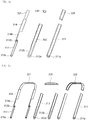
- the handle bottom 310 may include an outer frame 311, an inner frame 312 coupled to the outer frame 311, and a base frame 313 coupled to a sliding frame 314 and provided between the inner and outer frames 312 and 311.
- the sliding frame 314 may be coupled to the handle top 320 and/or a bottom frame 321 of the handle top 320.
- the sliding frame 314 may slide relative to the base frame 313 to raise a height of the handle top 320.
- the base frame 313 and sliding frame 314 may be collectively referred to as a middle frame.
- the sliding frame 314 may have a lower side 314b that couples to a gear or roller 313b provided on an upper end of the base frame 313.
- the lower side 314b of the sliding frame 314 may be narrower than an upper side of the sliding frame 314 coupled to the handle top 320.
- a surface of the lower side 314b that contacts the gear 313b may have teeth, and the teeth of the lower side 314b of the sliding frame 314 may correspond to teeth provided on an outer circumference of the gear 313b of the base frame 313.
- a lower end of the base frame 313 may include a motor 313a, which may rotate a belt coupled to the gear 313b.
- the gear 313b may rotate to move the lower side 314b of the sliding frame 314 up or down via the teeth of the gear 313b and the lower side 314b.
- An inner surface of the inner frame 312 may include a stopper flange 312b having a first end and a second end.
- the stopper flange 312b may be a raised or protruding portion around an edge of a lower side of the inner frame 312.
- the first end may prevent the lower side 314b of the sliding frame 314 from being slid further down the base frame 313, while the second end may be at a height higher than the first end to prevent a lower portion of the upper side of the sliding frame 314 from being slid further down the base frame 313.
- a height difference between the first and second ends of the stopper flange 312b may be equal to height difference between the lower end of the lower side 314b of the sliding frame 314 and a lower end of the upper side of the sliding frame 314.
- a contact between the handle top 320 and upper ends of the inner and outer frames 312 and 311 may also prevent the sliding frame 314 from being slid further down the base frame 313.
- the inner and outer frames 312 and 311 may include holes 312a and 311a, respectively, that surround an outer circumference of the motor 313a.
- the hole 311a may be a cavity or recess formed in the outer frame 311 to accommodate the motor 313a.
- the base frame 313 may include a hinge shaft on a side opposite to a side where the motor 313a is provided, and the hinge shaft may penetrate through the hole 312a of the inner frame 312 to couple to a hinge hole provided in the handle mount 153.
- the handle 300 may rotate via the hinge shaft of the base frame 313 and hinge hole of the handle mount 153.
- Lengths of the sliding frame 314, base frame 313, and inner and outer frames 312 and 311 may be configured such that when the sliding frame 314 is slid away from the base frame 313 by a maximum amount, the handle 300 may fit around the front ends (or alternatively, the back ends) of the upper and lower frames 140 and 150.
- the treadmill 1 may be conveniently stored when the handle 300 is rotated so that the outer, inner, base, and sliding frames 311, 312, 313, and 314 are provided to be parallel to a longitudinal length of the lower frame 150.
- a user may carry the treadmill 1 by holding onto the upper and lower frames 140 and 150 when the handle top 320 is folded or by grabbing the handle top 320 in such a folded position.
- the treadmill 1 When the handle 300 is folded to a first position, the treadmill 1 may be activated to be in a storage state.
- the handle bottom 310 may be parallel to a side of the base 100.
- various devices e.g., the blower 610, thermoelectric cooling assembly 630, and the fragrance assembly 500
- the photocatalytic deodorizer 622 and sterilizing lights 191 and 192 described later may be activated in the storage state to deodorize the treadmill 1.
- the treadmill 1 When the handle 300 is unfolded and rotated to a second position, the treadmill 1 may be activated to be in an exercise state.
- the cover 151 that covers the debris remover 180 may be coupled to the base 100 at a position that aligns with the handle mount 153, and sides of the cover 151 may be configured to prevent the handle 300 from rotating past the second position or past the first position. Sides of the cover 151 may serve as stoppers that limit the handle 300 within a rotation range defined by the first and second positions.
- a cover 151 may be provided to be detachable from the lower frame 150 to cover the debris remover 180 and the opening 152. When the user removes the cover 151, the user may remove the debris remover 180 to dispose of any debris caught by the debris remover 180.
- Sides of the cover 151 may have a curvature that corresponds to an outer contour of the side surfaces of the lower frame 150. The sides of the cover 151 may extend upward to be snap-fitted onto the side surfaces of the lower frame 150.
- a first end (e.g., a front end) of the cover 151 may have side surfaces that extend higher than side surfaces of a second end (e.g., a back end).
- the first edge may maintain the handle bottom 310 in a position that is parallel to the side of the base 100, and may limit a position of the handle bottom 310 past the first position.
- the angled edge may maintain the handle bottom 310 in an upright position where the handle top 320 crosses over the left and right belts 110 and 120, and may limit a position of the handle bottom 310 past the second position.
- the handle bottom 310 may be positioned at a predetermined angle away from a rear of the base 100.
- the predetermined angle may be an obtuse angle with respect to the rear of the base 100 or an acute angle with respect to the front of the base 100.
- the debris remover 180 may be a rectangular hollow container or tray having an opening or hole 183 through which hair, fur, lint, or other debris may enter.
- a height of the debris remover 180 may be configured so as to rest below the left and right belts 110 and 120 without contacting the floor.
- the opening 183 may be provided on a protruding portion of the debris remover 180 that extends upward toward the left and right belts 110 and 120, which may be exposed to the debris remover 180 via the opening 152 in the lower frame 150.
- the protruding portion of the debris remover 180 may have an angled edge close to or in contact with the left and right belts 110 and 120. When a pet sheds hair onto the left and right belts 110 and 120, the protruding portion of the debris remover 180 may scrape or brush off the hair, and the hair may fall into the opening 183.
- the protruding portion of the debris remover 180 may include a surface or scraper 184 configured to scrape debris off of the left and right belts 110 and 120 and induce a static charge, such as fabric, felt, sweeper, or a brush (e.g., microbrush, fine brush, or bristle brush) to catch hair and debris.
- a static charge such as fabric, felt, sweeper, or a brush (e.g., microbrush, fine brush, or bristle brush) to catch hair and debris.
- the surface or scraper 184 will be referred to as a brush 184.
- the brush 184 may also ionize the left and right belts 110 and 120 so that more hair may cling to the left and right belts 110 and 120 via static electricity instead of falling onto the lower frame 150 before reaching the opening 152 and the debris remover 180.
- the brush 184 and/or bristles of the brush 184 may have a stiffness that is sufficient to grab hair and clean a bottom surface of the left and right belts 110 and 120
- the opening 183 and brush 184 may be formed at an end end of the debris remover 180 to catch debris on a bottom section of the outer surfaces of the left and right belts 110 and 120, which may be moving in a backward direction (i.e., from a rear of the base 100 toward a front of the base 100) when a top section of the outer surfaces of the left and right belts 110 and 120 are moving in a forward direction (i.e., from the front of the base 100 toward the rear of the base 100) during an exercise program.
- the brush 184 may be provided on a leading edge of the opening 183 with respect to a movement of the bottom section of the outer surfaces of the left and right belts 110 and 120.
- the brush 184 and the opening 183 may extend below both the left and right belts 110 and 120.
- the debris remover 180 may include a lower frame 181 and an upper frame 182.
- the upper frame 182 may include the opening 183, and may be pressed-fit onto the lower frame 181.
- the lower frame 181 may include a cavity or space in which hair is stored, and the upper frame 182 may close the space.
- the lower frame 181 may further include a recess 181b formed in a bottom surface.
- the recess 181b may optionally serve as a tray to hold a film of water or gel and to capture hair or debris received through the opening 183 and prevent hair from escaping out of the opening 183.
- Optional vents 181a and 151a may be formed at ends (e.g., front ends) of the bottom frame 181 and the cover 151, respectively, to drain any excess water or gel in the recess 181b.
- a user may remove the cover 151 from the lower frame 150 to access the debris remover 180.
- the debris remover 180 may be removed from under the lower frame 150, and the user may separate the upper frame 182 from the lower frame 181 to empty the contents collected in the space of the debris remover 180.
- the user may also replace or refill water in the recess 181b.
- a back height adjuster 410 may control lengths of back left and right legs 411a and 412a to control a back inclination of the treadmill 1.
- the back height adjuster 410 may be provided on the back end of the lower frame 150 under the back frame 141 of the upper frame 140.
- the back frame 144 of the upper frame 140 may be provided on a top surface of a rear frame or shield 414 of the back height adjuster 410.
- the back left and right legs 411a and 412a may be inserted through holes provided on back corners of a bottom surface of the lower frame 140.
- the back height adjuster 410 may adjust the back left and right legs 411a and 412a via air suspension, as oil or other liquid used in hydraulic movement may interfere with a scent or smell released by the fragrance assembly 500.
- the back height adjuster 410 may include left and right air suspension compressors and pumps to independently adjust a height of the back left and right legs 411a and 412a, respectively.
- the back height adjuster 410 may include left and right air tanks 411 and 412, and at least one printed circuit board to independently control the left and right air tanks 411 and 412 and therefore a height adjustment of the left and right legs 411a and 412a based on signals received from the main controller of the control module 640.
- the left and right air tanks 411 and 412 may be coupled to a back side of the rear shield 414 of the back height adjuster 410.
- the rear shield 414 may serve as a frame that separates the back height adjuster 410 from the back rollers 111 and 121.
- the rear shield 414 may be fixed to the lower frame 150 so that when lengths of the back left and right legs 411a and 412a are lengthened, respective corners of the lower frame 150 are lifted to adjust an inclination of the treadmill 1.
- the left and right legs 411a and 412a of the back height adjuster 410 may each include an inner or lower pipe or piston inserted into an outer or upper pipe.
- the outer pipe may be fixed to the height adjuster 410 and/or the lower frame 150.
- the inner piston When the left air suspension compressor and pump is driven to pump air from the left air tank 411, the inner piston may be driven downward, and the outer pipe may rise relative to the inner piston to lift the left corner of the treadmill 1.
- An overlapping length of the inner piston and outer pipe may decrease during a lifting process, while the overlapping length is increased during a lowering process where the outer pipe may lower onto the inner piston as the inner piston is inserted further into the outer pipe.
- a front side of the rear shield 414 of the back height adjuster 410 may include a roller cover 194 to partially cover and/or divide the back rollers 111 and 121 from the back left and right air tanks 411 and 412.
- the back roller cover 194 may have a concave curvature so as not to interfere with a rotation of the back rollers 111 and 121.
- side surfaces of the rear shield 414 of the back height adjuster 410 may have a curved shape or concave opening so as not to interfere with a rotation of the back rollers 111 and 121.
- the left and right belts 110 and 120 may collect sweat, slobber, or bacteria during exercise.
- the left and right belts 110 and 120 may be sterilized or cleaned by back and front sterilizing lights 191 and 192 provided at the back and front ends of the treadmill 1, respectively.
- the back and front sterilizing lights 191 and 192 may face the left and right belts 110 and 120, and may sterilize a greater portion of the left and right belts 110 and 120 as the left and right belts 110 and 120 move.
- the back and front sterilizing lights 191 and 192 may operate in a storage mode, for a predetermined sterilization time period, or periodically at set intervals.
- the back sterilizing light 191 may include at least one ultraviolet (UV) light emitting diode (LED).
- UV ultraviolet
- LED light emitting diode
- the back UV LED 191 may emit UV light configured to kill or inactivate bacteria or other microorganisms, such as UV-C light (e.g., light having a wavelength between 220 - 280 nm).
- the back UV LED 191 may be provided on a front surface of a rear frame or shield 414 of the back height adjuster 410 to face the back left and right rollers 111 and 121.
- the rear shield 414 may have a top plate or portion configured to prevent UV light from being irradiated upward or outside of the upper frame 140.
- the back UV LED 191 may be provided above the roller cover 194.
- the roller cover 194 may include a sub-printed circuit board (PCB) to control an operation of the back UV LED 191 and/or a height adjustment of the left and right legs 411a and 412a.
- PCB sub-printed circuit board
- the back UV LED 191 may have a length extending in a longitudinal direction of the back left and right rollers 111 and 121, and may be provided at a center such that a left portion of the back UV LED 191 sterilizes the left belt 110, and a right portion of the back UV LED 191 sterilizes the right belt 120.
- the front sterilizing light 192 may similarly include at least one UV LED.
- the front sterilizing light 192 will be referred to as a front UV LED.
- the front UV LED 192 may emit UV light configured to kill or inactivate bacteria or other microorganisms, such as UV-C light (e.g., light having a wavelength between 220 - 280 nm).
- the front UV LED 192 may be provided on a back surface of a front roller cover 193.
- the front roller cover 193 may separate the front rollers 112 and 112 from a front portion of the base 100 including the blower 610 and the fragrance assembly 500 described later.
- the front roller cover 193 may have side surfaces that are curved or have concave openings so as not to interfere with a rotation of the front rollers 112 and 122.
- the front UV LED 192 may have a length extending in a longitudinal direction of the front left and right rollers 112 and 122, and may be provided at a center of the front roller cover 193 such that a left portion of the front UV LED 192 may sterilize the left belt 110 and a right portion of the front UV LED 192 may sterilize the right belt 120.
- the front UV LED 192 may be provided in an upper portion or side of the front roller cover 193, while a PCB may be optionally provided in a lower side of the front roller cover 193 to control an operation of the front UV LED 192.
- a shape of the front roller cover 193 may be configured to prevent UV light from being irradiated upward or outside of the upper frame 140.
- the front roller cover 193 may divide the left and right belts 110 and 120 from a space under the front frame 141 that includes the fragrance assembly 500, the blower 610, and the front height adjuster 420 (see FIG. 4 ).
- the front height adjuster 420 may operate similarly to the back height adjuster 410 via air suspension.
- the front height adjuster 420 may include front left and right legs 421a and 422a that are independently controlled by left and right air suspension compressors and pumps and at least one printed circuit board.
- the front height adjuster 420 may include left and right air tanks 421 and 422, and the printed circuit board may independently control the left and right air tanks 421 and 422 based on signals received from the main controller of the control module 640.
- Each of the front left and right legs 421a and 422a may include an outer or upper pipe or piston and an inner or lower pipe.
- an air pressure is applied by, e.g., the left air tank 421
- the outer pipe of the front left leg 421a may rise relative to the inner pipe or piston to raise a height of the front left leg 421a and therefore a front left corner of the treadmill 1.
- the four legs 411a, 412a, 421a, and 422a of the treadmill 1 may be provided at or near corners of the base 100 and independently controlled so that a tilt or inclination of the treadmill 1 may be varied and customized according to a program played on the display 210.
- the front left and right legs 421a and 422a may extend from a lower surface of the front support 420. When a height of at least one of the front right and left legs 421a and/or 422a is adjusted, heights of corresponding corners or sides of the upper and lower frames 140 and 150 may also be adjusted.
- the front height adjuster 420 may raise, via the front left and right air suspensions compressors and pumps, the front left and right legs 421a and 422a by equal amounts to create a constant inclination of the treadmill 1 to correspond to, for example, a hill program.
- the front height adjuster 420 may raise, via the front right air suspension compressor and pump, only the front right leg 422a
- the back height adjuster 410 may raise, via the back left air suspension compressor and pump, only the back left leg 411a to simulate a rocky or mountain terrain.
- a stand 424 may be coupled to the front support 423.
- the front frame 141 of the front support 420 may be provided on an upper surface of the front support 423 to cover the left and right air tanks 421 and 422.
- the front end of the lower frame 150 may also be securely fixed (e.g., bonded or welded) to sides of the front support 423.
- the stand 424 may serve as a base or support when the treadmill 1 is stored (see FIG. 5B ).
- the stand 424 may be coupled to a display mount 211 described later when the attachment module 200 is attached.
- the blower 610 may be a radial bladed fan or wheel 610 provided at a front of the treadmill 1.
- the deodorizer 620 and the thermoelectric cooling assembly 630 may also be provided at the front of the treadmill 1.
- the blower 610 may be a tangential fan or cross-flow blower to disperse scents from the fragrance assembly 500, disperse cool or warm air from the thermoelectric cooling assembly 630, and/or disperse air deodorized by the photocatalytic deodorizer 622 of the deodorizer 620.
- the blower 610 may have a cylindrical shape and a length corresponding to a length of the front frame 144 and/or a length corresponding to a length of the vents 146 to facilitate laminar air flow through the vents 146.
- the thermoelectric cooling assembly 630 may include a thermoelectric cooler (TEC) or Peltier device 633. Above and below the Peltier device 633 may be top and bottom heat sinks 634 and 632, respectively.
- the top and bottom heat sinks 634 and 632 may each have a heat dissipation plate provided on the Peltier device 633, and may have radiating fins extending upward and downward, respectively, from the heat dissipation plates of the top and bottom heat sinks 634 and 632.
- the Peltier device 633 may electrically connect to a control module 640 described later, and may receive a current to cool or warm air dispersed through the vents 146 by the blower 610. When a voltage is applied to the Peltier device 633, heat may be transferred from a first side (e.g., upper side) to a second side (e.g., bottom side) such that there is a temperature difference between the first and second sides.
- a first side e.g., upper side
- a second side e.g., bottom side
- a fan 631 may be provided below the bottom heat sink 634 and above discharge holes 154 ( FIG. 5 ) provided in a bottom surface of the lower frame 150.
- a motor may rotate a shaft of the fan 631 to exhaust hot air during a cooling process (or alternatively, cool air in a heating process) dissipated by the bottom heat sink 634 through the discharge holes 154.
- the upper side of the Peltier device 633 may become cold, causing the top heat sink 632 to become cold, resulting in a drop in temperature of the ambient air, which is blown by the blower 610.
- the bottom side of the Peltier device 633 may become hot, causing the bottom heat sink 634 to become hot, resulting in an increased temperature of the ambient air, which his exhausted out of the discharge holes 154 by the fan 610.
- the upper side of the Peltier device 633 may become hot, and hot air near the top heat sink 632 may be drawn through the vents 146 via the blower 610.
- the bottom side of the Peltier device 633 may become cold, and cold air may be exhausted out of the discharge holes 154 via the fan 610.
- a temperature of the pet may be sensed by the handle sensor 331 and/or the left and right proximity sensors 132 and 133, which may include an infrared sensor or a thermometer. Alternatively or in addition thereto, there may be another optional temperature sensor.
- a temperature of the pet and/or ambient air may be maintained, via an operation of the Peltier device 633, at a predetermined temperature or temperature range.
- the ambient air above the left and right belts 110 and 120 and/or surrounding the treadmill 1 may be maintained at a temperature between 15 - 18 °C or between 59 - 65° F.
- the fan 631 may rotate at a greater speed than the blower 610 and may generate a greater airflow than the blower 610.
- the deodorizer 620 may neutralize pollutants or odor particles in the air above the left and right belts 110 and 120.
- the deodorizer 620 may include two LED modules 623 protruding from a photocatalyst housing 624 and oriented toward a photocatalytic deodorizer 622.
- the LED modules 623 may each include at least one light emitting diode and emit light of a visible wavelength of a specific color temperature, e.g., 1,000 - 10,000 kelvin, on the photocatalytic deodorizer 622. Alternatively, the LED modules 623 may emit UV light.
- the photocatalyst housing 624 may be provided to house and surround the photocatalytic deodorizer 622.
- the photocatalyst housing 624 may have an opening or hole through which the photocatalytic deodorizer 622 is exposed toward the LED modules 623.
- a bottom surface or side of the LED modules 623 may be coupled to an upper surface of the photocatalyst housing 624, and the LED modules 623 may be positioned to be inclined so that the light emitting diode may emit light toward the photocatalytic deodorizer 622.
- the LED modules 623 may have a length less than or equal to a length of the sides of the photocatalyst housing 624 on which they are mounted.
- the photocatalytic deodorizer 622 may be made of or coated in a material having strong oxidizing properties (e.g., titanium or titanium dioxide (TiO 2 )) so when the LED modules 623 shine light on the photocatalytic deodorizer 622, the photocatalytic deodorizer 622 may be activated to release or emit electrons or ions that react with the air at or near the treadmill 1 to break apart pollutants.
- the blower 610 may disperse the emitted ions through the vents 146 to deodorize air outside of the base 100.
- the deodorizer 620 may remove odors from the air around the treadmill 1 and/or a pet or pet odor remaining on the treadmill after the pet has exercised or while the pet is exercising.
- the deodorizer 620 may operate when the treadmill 1 is not being used and the fragrance assembly 500 is in a closed state so as not to emit any scents or fragrances, which can be neutralized by the ions.
- the control module 640 may also be provided in the space between the front roller cover 193 and the second height adjuster 420.
- the control module 640 may be provided under the photocatalytic deodorizer 622, and may include a main controller on a main printed circuit board (PCB) that controls a power supply to the motors of the fans 631, the motor 313a of the handle 300, an operation of the display 210, etc.
- the control module 640 may further include an alternating current/direct current (AC/DC) converter to convert external AC power to DC power to power the fans 631, motor 313a, display 210, UV LEDs 191 and 192, LED modules 623, etc.
- External power may be applied to a terminal or socket provided on the base 100 of the treadmill 1.
- the terminal or socket may be provided at the front end of the base 100 and may be electrically coupled to the control module 640.
- the control module 640 may have a communication module to communicate with communication modules of other devices (e.g., communication modules of the back and front height adjusters 410 and 420 or in the sensor assembly 330 of the handle 300).
- the communication module of the control module 640 may also communicate with a server, and/or may include a WiFi or Bluetooth module so that a user (e.g., pet owner) may control the treadmill 1 from a mobile or web application.
- a user e.g., pet owner
- the owner's image/video and voice may be provided on the display 210 with audio, and an embedded camera and microphone on the display 210 may be used to transmit the pet's image/video to a mobile or remote device (e.g., computer or mobile phone) via the communication module.
- a mobile or remote device e.g., computer or mobile phone
- the communication module of the control module 640 may also interact with a pet pendant or pet identification tag having a GPS tracker.
- the main controller determines that the owner is away (based on GPS data from the owner's phone) but that the pet is still at home (based on GPS data from the GPS tracker in the pet pendant)
- the treadmill 1 may turn on the display 210, dispense treats on the dispensing tray 220, or emit smells or scents via the fragrance assembly 500 to lure the pet to the treadmill 1.
- a luring and rewards process will be described in more detail later after describing the fragrance assembly 500 and display 210.
- the fragrance assembly 500 may include a cartridge 504 having a plurality of scent modules 505 provided in the cartridge 504.
- the cartridge 504 may be provided in an inner case 502 having an opening 502a through which the scent modules 505 are exposed, and the cartridge 504 may rotate to expose a particular scent module 505 through the opening 502a of the inner case 502.
- the blower 610 may rotate to disperse a scent and/or fragrance from the exposed scent module 505 through the vents 146 and to a pet using the treadmill 1.
- the cartridge 504 may be divided into sections by tabs or walls, and different scent modules 505 may be provided in different sections of the cartridge 504. Shapes of the scent modules 505 may correspond to shapes of the sections of the cartridge 504 in which the scent modules 505 are inserted. As exemplified in the figures, the cartridge 504 may be formed by four vertical walls perpendicular to each other and intersecting at a center to create four 90° corners. Side ends of the cartridge 504 may each have a circular cap.
- the four vertical walls may have a length that is parallel to a length of the blower 610.
- the scent modules 505 may have a length equal to or less than the length of the four vertical walls.
- the scent modules 505 may resemble elongated wedges having 90° corners that are inserted into the corners created by the four vertical walls, and having a curved or arc-shaped circumference to match a curvature of the cap provided at the sides of the cartridge 504.
- the scent modules 505 When the scent modules 505 are inserted into the cartridge 504, the cartridge 504 and the scent modules 505 may together form a cylinder.
- the scent modules 505 may be made of a scented oil, wax, or gel that is in a primarily solid state that vaporizes when a temperature is slightly risen and/or emits scented vapor or fragrances.
- the scent modules 505 may be made of an absorbent or sponge-like material (e.g., felt) that is soaked in a liquid fragrance material.
- the blower 610 may draw out and disperse the scent provided by the scent modules 505. As pets may be sensitive to smell, the blower 610 may draw out the scent provided from the scent modules 505 instead of blowing or pushing the scents from behind the fragrance assembly 500. Such a configuration of the blower 610, fragrance assembly 500, and vents 146 may reduce a possibility of mixing smells.
- each scent module 505 may have an optional neutral smelling or protective layer to serve as a barrier, and the scent released from the scent module 505 may be stronger or dispersed further when the blower 610 rotates, and may be weaker or not dispersed very far when the blower 610 stops rotating.
- the cartridge 504 may hold a first scent module 505 that emits a flower flagrance to correspond to a video displaying flowers along a road or trail played on the display, a second scent module 505 that emits a sea or beach fragrance to correspond to a seaside or beach video played on the display, a third scent module 505 that emits phytoncide or a forest fragrance to correspond to a forest or woods themed video played on the display, and a fourth scent module 505 that emits no fragrance or a neutral fragrance.
- a fourth section of the cartridge 504 may not include a fourth scent module 505 and may remain empty.
- the cartridge 504 may be placed between two side supports 503a and 503b, and the cartridge 504 and the side supports 503a and 503b may be placed in the inner case 502. At least one of the side supports 503a or 503b may include a motor to rotate the cartridge 504. In FIG. 26 , side support 503b includes a motor.
- the inner case 502 may have a hollow, truncated cylinder shape.
- the inner case 502 may have an opening 502a that is cut into a bottom or side surface, and the opening 502a may have a shape that corresponds to a shape of one scent module 505.
- the opening 502a may be slightly smaller than the shape of the scent module 505 (e.g., the opening 502a may have an 88° corner) so that no other scents from other scent modules 505 may be exposed through the opening 502a.
- the cartridge 504 may rotate so that only one scent module 505 is exposed through the opening 502a.
- a rotation of the cartridge 504 may be automatic via the motor, and a fragrance emitted by the fragrance assembly 500 to the pet may be changed by a change of an exposed scent module 505 via a rotation of the cartridge 504.
- the first scent module 505 having a flower or floral fragrance may be exposed through the opening 502a when a flower program or flowery road is played on the display 210.
- the cartridge 504 may rotate in the inner case 502 until the third scent module 505 emitting a phontycide or forest scent is exposed through the opening 502a.
- the cartridge 504 may rotate to expose the blank, fourth scent module 505 to close the fragrance assembly 500.
- the cartridge 504 may be rotated to expose the fourth scent module 505 when the treadmill 1 is in a storage state, when the treadmill 1 is not being used, and/or when the deodorizer 620 is operated. Therefore, the other odors of the scent modules 505 will not break down by the ions emitted by the photocatalytic deodorizer 622.
- the opening 502a may be closed by an optional automatic gate provided in the inner case 502a.
- the inner case 502 holding the cartridge 504 may be placed into the cartridge case 501.
- the cartridge case 501 may have a truncated cylinder shape.
- a cover or lid 506 may be configured to close a flat or truncated upper opening of the cartridge case 501 so that unintended fragrances do not escape or are not emitted toward the pet using the treadmill 1.
- the cover 506 may be pressed fit onto the cartridge case 501, and may have grooves or recesses formed in an upper surface in which a user may wedge a finger or nail to remove the cover 506 from the cartridge case 501 to access the cartridge 504.
- the cartridge 504 may be formed to be durable, and the scent modules 505 may be easily removed from the cartridge 504 and replaced. Alternatively, the cartridge 504 may be formed integrally with the scent modules 505, and may be disposed and replaced when the scent modules run out of fragrance.
- a lower or side surface of the cartridge case 501 may have an opening or vents at a position that corresponds to a position of the opening 502a of the inner case 502 so that fragrance or scent from an exposed scent module 505 may be dispersed to the vents 146 via the blower 610.
- the scents released by the fragrance assembly 500 may be coded into information that is part of a predetermined exercise program such that at certain time intervals, certain scents are released.
- Content on the display 210 may also be part of the predetermined exercise program, and the fragrance assembly 500 and content on the display 210 may correspond to each other as time progresses.
- the attachment module 200 may include a display 210 to play videos or exercise programs or display a user interface to manually control an operation by the user.
- the display 210 may include at least one speaker and a camera. Content played on the display 210 may be frequently changed so as to continue to stimulate the pet.
- the attachment module 200 may further include a display mount 211, a container 230 to hold food or treats, a lid 231 ( FIG. 3 ) that may be removed to refill the container 230 with treats, and a dispensing tray 220 on which treats from the container 230 may be dispensed.
- the dispensing tray 220 may include a tray or dispensing container 221 which may couple to the container 230 and support the display mount 211, and an attachment base 240 that couples to the dispensing tray 220 and the tray container 221 to the stand 424 of the second height adjuster 420.
- the display 210, display mount 211, container 230, dispensing tray 220, tray container 221, and attachment base 240 may be removable, and a user may choose to only attach, as an example the display 210 and the attachment base 240.
- the attachment base 240 may be a plate having a rectangular or square shape.
- a lower side or portion of the attachment base 240 may be coupled to an upper side or portion of the stand 424.
- the lower side of a back surface of the attachment base 240 may have a protrusion which may be inserted into a recess or groove provided in an upper side of a front surface of the stand 424.
- the recess or groove of the stand 424 may have a recessed cylindrical shape corresponding to a cylindrical shape of the protrusion of the attachment base 240.
- the protrusion of the attachment base 240 may be pressed-fit into the recess of the stand 424 to be removable so that the entire attachment assembly 200 may be removed from the treadmill 1.
- the tray container 221 may have an upper hole or opening that communicates with a bottom hole or opening of the container 230.
- the tray container 221 may also have a lower hole or opening so that treats stored in the container 230 may fall through the bottom hole of the container 230, the upper hole of the tray container 221, and the lower hole of the tray container 221 onto the dispensing tray 220.
- At least one of upper and lower holes of the tray container 221 and or the bottom hole of the container 230 may have a gate that is automatically driven to selectively open and close.
- the gate may open when it is time to dispense a treat (e.g., during a luring process or during a rewards process), and may close to prevent treats from falling onto the dispensing tray 220 (e.g., during an exercise process or in a storage state).
- the container 230 may be a hollow container formed of front and back walls, side walls, an upper wall and lid 231, and an optional bottom wall having an opening.
- the side walls and front and back walls may be pressed fit onto grooves provided on an upper surface of the tray container 221.
- the container 230 may be easily removable from the tray container 221 so that a user may clean or refill treats stored in the container 230.
- the lid 231 FIG. 3 ) provided on a top of the container 230 may allow a user to quickly refill the container 230, or alternatively may be a handle that allows a user to remove the container 230 from the tray container 221.
- the tray container 221 may be a hollow container formed of front and back walls, side walls, an upper wall, and an optional bottom wall.
- the tray container 221 may be formed separately from the dispensing tray 220 and later combined, or the tray container 221 and the dispensing tray 220 may be formed together (e.g., injection molded) as a single element.
- the tray container 221 and the dispensing tray 220 may be made of plastic or, alternatively, metal.
- a bottom end of the display mount 211 may be provided on and supported by the upper wall of the tray container 221.
- the display mount 211 may be a plate having, for example, a rectangular or square shape.
- the front wall of the container 230 may be inclined backward from a lower end to an upper end.
- a back surface of the display mount 211 may have a shape and inclination corresponding to a shape and inclination of the front wall of the container 230 and may be provided on the front wall of the container 230.
- a size of the display mount 211 may be equal to or smaller than a size of the front wall of the container 230.
- the display mount 211 may be larger than the front wall of the container 230 and/or protrude above the front wall of the container 220.
- the display mount 211 may be removably coupled to the container 230.
- the display mount 211 may be coupled magnetically to the container 230.
- the container 230 may have rail guides, and a back of the display mount 211 may have rails that slide into the rail guides.
- the display 210 may be optional, and a user may customize the attachment module 200.
- the display 210 may be coupled directly to the stand 424.
- the display 210 may have a fixed inclination or orientation.
- a back surface of the display 210 may be configured to couple to a front surface of the stand 424 via, e.g., a groove in the front surface of the stand 240 and a corresponding protrusion on a back surface of the display 210.
- FIG. 28B exemplifies an attachment module 200 where the display 210 and the display mount 211 are omitted.
- FIG. 28C exemplifies an attachment module 200 where the dispensing tray 220, tray container 221, container 230, and display mount 211 are omitted.
- the display 210 may be a liquid crystal display (LCD) backlit by light emitting diodes (LEDs) or organic light emitting diodes (OLEDs).
- the display 210 may have a communication and/or WiFi or BlueTooth module so that videos (e.g., DogTV videos) may be streamed on the display 210 and/or a remote owner may communicate with a pet on the treadmill 1 via, e.g., FaceTime or Skype, or via a mobile/web application executed by the remote user (i.e., a pet owner).
- Applications typically requiring input by callers to accept or place a call may be modified to be controlled by the pet owner and/or be implemented in a mode that automatically accepts calls.
- Videos streamed on the display 210 may be also designed for pets, and may show certain shades of colors (e.g., yellow, blue, gray, and/or green) for dogs.
- the videos played on the display 210 may have a relatively high refresh rate or flicker frequency (e.g., at least 100 Hz) so that a pet may perceive the images as continuous.
- the display 210 may also emit sounds at a relatively high frequency (e.g., 47,000-75,000 Hz) to stimulate the pet.
- the display 210 may further include a camera or webcam so that the owner may see the pet, and/or images from the handle sensor 331 may be accessed online or via a mobile application.
- the display 210 may also be configured to play pre-recorded exercise programs, which may be programmed in conjunction with the fragrance assembly 500, the blower 610, and/or the back and front height adjusters 410 and 420.
- the display 210 may have a printed circuit board that electrically connects to the control module 640.
- the display 210 and/or the control module 640 may include a memory or storage to store exercise data about how often, how long, and how far a pet has exercised.
- the dispensing tray 220 may provide a surface on which treats stored in the container 230 may be dropped.
- the dispensing tray 220 may have curved sidewalls so as to prevent treats from being dropped off the sides of the dispensing tray 220. Treats may remain on the dispensing tray 220, or alternatively a curvature and inclination of the dispensing tray 220 may be configured to guide treats onto the left and right belts 110 and/or 120.
- the vents 146 may be automatically closed, and the left and right belts 110 and/or 120 may be slowed down or stopped (i.e., the motors 123 and 113 may slow down or stop a rotation of the front right and back left rollers 122 and 111) so that a pet may safely consume the treat.
- the vents 146 may include provided in the opening 147 of the front frame 141.
- a section of the front frame 141 including the opening 147 and vents 146 may be an inclined surface having an inclination that is equal or similar to an inclination of a lower surface of the front portion of the divider 130.
- the front end of the divider 130 may be coupled to the inclined surface of the front frame 141 between left and right sets of vents 146.
- the vents 146 may be vanes that are adjustable automatically via a motor provided at ends of the vents 146.
- the vents 146 When the treadmill 1 is in a storage mode, the vents 146 may be adjusted to be closed. A degree of opening of the vents 146 may be adjusted to correspond to an exercise program played on the display 210 (e.g., a windy program) or based on a predicted exertion, exhaustion, or temperature of the pet.
- the handle sensor 331 may have an infrared sensor (e.g., passive infrared sensor or PIR) to sense a temperature and/or movement of the pet. When a certain temperature or temperature increase is sensed by the temperature sensor, the vents 146 may be opened to a degree corresponding to a degree of the temperature increase, and/or the Peltier device 633 may be operated to provide cool air.
- infrared sensor e.g., passive inf
- a degree of opening of the vents 146 may also be controlled to control a strength of scents emitted by the fragrance assembly 500.
- the vents 146 may be opened to a maximum degree so that a pet is exposed to a maximum scent strength.
- the vents 146 may be closed to prevent or minimize the scent strength.
- the vents 146 may be automatically closed when the fragrance assembly 500 is switching between different scents or smells.
- a scent strength may be increased by increasing speed of the blower 610 and/or by increasing a temperature of the air around the fragrance assembly 500 via the Peltier device 633 to facilitate a vaporizing of the scent modules 505.
- the control module 640 may communicate with various circuitry on the PCBs of the back and front height adjusters 410 and 420 so that an inclination of the treadmill 1 may be adjusted to scoot or encourage the pet to move back into the predetermined lateral distance range. For example, if the control module 640 determines that a pet is too far to the left and outside of the predetermined lateral distance range, the left front and back legs 421a and 411a may be lengthened so that the treadmill 1 is inclined downward in a left-right direction. The pet may fall or be guided toward the right. When it is determined that the pet is within the predetermined lateral distance range, the left front and back legs 421a and 411a may be shortened back to an initial position, and/or pre-programmed inclinations according to an exercise program may be continued.
- control module 640 may also calculate a gait when a pet is too far to the left or too far to the right. If the control module 640 determines that a pet is too far to the left and outside of the predetermined lateral distance range, the control module 640 may determine that a stride length of the pet's right leg is greater than a stride length of the pet's left leg. The control module 640 may control the right motor 123 to increase a speed of the right belt 120 and/or may control the left motor 113 to decrease a speed of the left belt 110.
- a speed sensor may be provided in at least one of the motors 123 and/or 113, or alternatively on the lower frame 150 near one of the rollers 111, 112, 121, 122 to sense a linear speed of the left and/or right belts 110 and 120.
- the control module 640 may determine a speed of the left and right belts 110 and 120 based on an operation of the left and right motors 113 and 123.
- a memory or storage provided in the control module 640 may record information on how fast or how far a pet has traveled during exercise.
- a user may select a "speed link" option so that exercise programs or other content played on the display 210 correspond to a speed of the left and right belts 110 and 120 of the treadmill 1.
- a basic or initial speed of the left and right belts 110 and 120 may be set to be at or around a natural walking speed (e.g., 4 km/h or roughly 2.5mph).
- the "basic speed" of the left and right belts 110 and 120 may be defined as an average speed of the left and right belts 110 and 120.
- the display 210 may display content (e.g., a family picture, a calming image, DOG TV, or other sound, image, or video) regardless of (or independent from) a speed of the left and right belts 110 and 120. If the "speed link" option is selected, however, the content will play at a normal or regular speed when the left and right belts 110 and 120 are travelling at the basic speed. The normal or regular speed of the content played on the display 210 may simulate or represent the basic speed. If the main controller in the control module 640 determines a change in the average speed of the left and right belts 110 and 120, then the main controller may operate the display 210 to proportionately change a speed of the displayed content.
- content e.g., a family picture, a calming image, DOG TV, or other sound, image, or video
- the content on the display 210 may be played at 1.5 times the normal or regular speed. If it is sensed or determined that the average speed of the left and right belts 110 and 120 has decreased from a basic speed of 4km/h to 3km/h (roughly 1.9 mph), then the content on the display 210 may be played at 0.75 times the normal or regular speed.
- the treadmill 1 may operate differently when an owner is away from the home versus when the owner is in the home.
- the communication module in the control module 640 of the treadmill 1 may interact with a mobile application or GPS data from a user's cell phone to determine whether the owner is home.
- an operation of the treadmill 1 may be initiated by the owner, an operation may end 15 minutes later, and a treat may be dispensed on the dispensing tray 220.
- the attachment module 200 may not dispense a treat or reward at the end of the exercise, and the owner may determine whether or not to give his pet a treat.
- the treadmill 1 may initiate a luring or attraction process until the pet has exercised a predetermined number of times (e.g., four times or two times) during a predetermined time period (e.g., a day or an eight hour period).
- the control module 640 may have a timer or clock and a memory or storage, and may collect data on how often the treadmill 1 is used.
- the communication module of the control module 640 may also interact with a pet pendant or pet tag attached to a particular pet, so when multiple pets live in a single household, the control module 640 may be able to collect data on how often a particular pet has used the pet treadmill 1.
- the main controller of the control module 640 may first determine whether the treadmill 1 has been used that day (or alternatively, whether a particular pet has exercised yet that day). When it is determined that the treadmill 1 has not yet been used, the display 210 may be controlled to display content that may be pleasing for pets to lure the pet to the treadmill 1. For example, the display 210 may show images of other pets, play sounds of other animals, or stream programs from programs designed for pets (e.g., DogTV).
- the fragrance assembly 500 may emit a scent or fragrance (e.g., flower scent or an optional meat or food scent) from one of the scent modules 505 to spark curiosity in the pet.
- the gate in the attachment module 200 may be controlled to be open so that a treat is dispensed from the container 230 to the dispensing tray 220 to reward the pet for boarding.
- the left and right belts 110 and 120 may be turned very soon after dispensing (e.g., half a second or less) to keep the pet's attention and to prevent the pet from jumping off the treadmill 1 before an exercise program is started.
- operation of the treadmill 1 may end a predetermined program time (e.g., 15 minutes) later, and a reward or treat may be dispensed.
- a treat may be dispensed after a pet has exercised for a certain amount of time (e.g., 5 minutes) or exercised a predetermined distance (e.g., 0.3 miles).
- a predetermined distance e.g., 0.3 miles.
- the main controller determines (via the handle sensor 331, the proximity sensor in the divider 130, or optional weight sensors in the lower frame 150) that a pet has not boarded the treadmill 1, the display 210 may play different content to attract the pet including sound and video of the owner, which may have been pre-recorded and stored in the memory or may be lived streamed from the owner using the mobile/web application upon notification of a failed luring attempt to the owner.
- the attachment module 200 may also dispense a preliminary treat to lure the pet onto the pet treadmill 1.
- the left and right belts 110 and 120 may be immediately rotated after the determination without regard for whether the pet is centered or properly positioned on the left and right belts 110 and 120 to prevent the pet from jumping off the treadmill 1 after consuming the treat but before exercising.
- an operation of the treadmill 1 may be stopped, and a luring process may be restarted after a predetermined reattempt time (e.g., after 15 minutes, an hour, etc.) If the pet was lured to the treadmill 1 and finished an exercise program, the luring process may be restarted after a predetermined rest time (e.g., after four hours) to encourage the pet to use the treadmill 1 again later in the day.
- a memory in the main controller may store information on how often the luring process was initiated and how often and when the pet exercised, and an owner may access that information via the display 210 or a mobile application.
- speeds of the left and right belts 110 and 120 may be adjusted based on a forward-backward position sensed by the handle sensor 331. Such adjustments may override any predetermined speeds of the left and right belts 110 and 120 as part of a predetermined exercise program. If it is determined by the main controller in the control module 640 that the pet is properly positioned and/or centered based on a sensed position by the handle sensor 331, then the speeds of the left and right belts 110 and 120 may be maintained. However, if the main controller determines that the pet is in front of a predetermined position or a predetermined position range, speeds of the left and right belts 110 and 120 may be increased by equal amounts.
- a forward-backward inclination of the treadmill 1 may be adjusted via the front and back height adjusters 420 and 430 based on a forward-backward position sensed by the handle sensor 331. If it is determined by the main controller in the control module 640 that the pet is properly positioned and/or centered based on a sensed position by the handle sensor 331, then the inclination of the treadmill 1 may be maintained.
- a memory in the main controller may store information on how often the inclination of the treadmill 1 changes and to what degree, and the owner may access that information via the display 210 or a mobile application.
- an inclination of the treadmill 1 may be adjusted based on a left-right position of the pet sensed by proximity sensors in the divider 130 by adjusting lengths of the legs 411a, 412a, 421a, and 422a. Such an adjustment may override any predetermined inclinations of the treadmill 1 as part of an exercise program.
- the left proximity sensor 132 may measure how far to the left a pet may be positioned, and the right proximity sensor 133 may measure how far to the right a pet may be positioned.
- the left-right position of the pet may indicate a gait, and speeds of the left and right belts 110 and 120 may be changed in response to positions sensed by the proximity sensors 132 and 133. If it is determined that the pet is too far to the left, then a speed of the left belt 110 may be decreased via the left motor 113 and/or a speed of the right belt may be increased via the right motor 123. If it is determined that the pet is too far to the right, then a speed of the left belt 110 may be increased via the left motor 113 and/or a speed of the right belt may be decreased via the right motor 123. If it is determined that the pet is within the predetermined lateral distance, then continuous exercise may be implemented and an inclination of the treadmill 1 may not be altered in response to a pet position.
- the main controller may control, either directly or interacting with other communication modules, operations of the back and front LEDs 191 and 192, the back and front height adjusters 410 and 420, the vents 146, the left and right proximity sensors 132 and 133, and the left and right motors 113 and 123.
- the main controller may further control an operation of the motor 313a and handle sensor 331 in the handle 300 and the motor in the side support 503b of the fragrance assembly 500.
- the main controller may control an operation of the display 210, an inclination of the display 210 via the display mount 211, and a dispensing of treats via the gate in the container 230.
- the main controller may control an operation of the blower 610, the fans 632, the Peltier device 633, and the LED modules 623 that activate the photocatalytic deodorizer 622.
- the main controller may make determinations and control operations of the various electronic devices based on sensed measurements by the handle sensor 331, and the left and right proximity sensors 132 and 133. Sensed measurements may be recorded and stored in the memory, and the main controller may make future determinations based on data stored in the memory. A user may access data stored in the memory via the display 210 or on a mobile application installed on a mobile device that communicates with the communication module.
- the front and back height adjusters 410 and 420 may alternatively operate via a gear method instead of air suspension.
- Figures 37A and 37B show a gear method for the front height adjuster 420, but a similar method may be applied to the back height adjuster 410.
- the front frame 141 of the upper frame 140 and the front end of the lower frame 150 may be fixed to the stand 424, which may be slideably coupled to the front support 423.
- the front support 423 may be provided in a pair to correspond to left and right front legs 421a and 422a, or may have a slit in a center.
- a gear 423a may have a support or center frame 423b that is fixed to the stand 424.
- the support 423b of the gear 423a may extend between the pair of front supports 423 or alternatively be inserted through the slit of the center of the front support 423.
- the support 423b of the gear 423a may extend in a longitudinal direction of the treadmill 1, while the gear 423a may protrude laterally from the support 423b (e.g., toward the right or left) to interact with a back surface of the front support 423.
- the back surface of the front support 423 may have teeth that interact with teeth of the gear 423a, which may turn manually or via a motor.
- the gear 423a turns in a first direction
- the front support 423 may be slid downward with respect to the stand 424, and the upper and lower frames 140 and 150 may rise.
- the gear 423a turns in a second direction
- the front support 423 may be slid upward with respect to the stand 424 and inserted into the treadmill 1 to lower the upper and lower frames 140 and 150.
- the treadmill 1 is described as being used by an animal or pet, embodiments disclosed herein may also be modified (e.g., made bigger) to be used by humans. For example, people who have injured their legs or who otherwise have gait may not be able to use a standard one-belt treadmill, especially during physical therapy after a recent injury.
- the treadmill 1 having left and right belts 110 and 120 may be implemented as a human treadmill, and speeds of the left and right belts 110 and 120 may be adjusted to accommodate a human's gait.
- a treadmill 1 may be applied to any number of exercise apparatuses.
- a stair master machine may have separate right and left tracks, an attachment module, and/or a fragrance assembly.
- the first and second belts 110 and 120 may alternatively be referred to as first and second moveable members, tracks, treads, panels, or stair assemblies.
- the upper and lower frames 140 and 150 may be made of metal such as stainless steel to provide a stable, durable base.
- a treadmill 1 made of metal upper and lower frames 140 and 150 may be advantageous in a dog kennel setting where many different dogs may use the treadmill 1 throughout the day.
- the upper frame 140 may be bonded or welded to the lower frame 150.
- the upper and lower frames 140 and 150 may alternatively be bonded or welded together instead of being pressed-fit or snapped-fit to each other.
- a pressed-fit coupling between the upper and lower frames 140 and 150 may facilitate a removal and replacement of the left and right belts 110 and 120.
- the upper frame 140 may be manufactured as a single upper frame 140, or alternatively, the back frame 144, the side frames 145, and the front frame 141 may be manufactured separately and then later pressed-fit or bonded together for integration.
- the lower frame 150 may similarly be manufactured as a single lower frame 150 or alternatively, the lower frame 150 may include a separate front frame, side frames, and back frame that are pressed-fit or bonded together for integration.
- one of the rollers may be replaced by a fixed shaft or pipe.
- the shaft may be formed of or coated in a slippery material such that there is not much friction between the belt 120 and the shaft, and the belt 120 may primarily rotate around one roller at a first end and pass over the slippery end of the shaft at the second end.
- rollers 111, 112, 121, and 122 may be optional guide or tab provided on the upper frame 140, lower frame 150, and/or on side surfaces of the rollers 111, 112, 121, and 122 to keep the left and right belts 110 and 120 in place and aligned on the rollers 111, 112, 121, and 122.
- the front and back roller frames 142b and 142a may include an optional locking mechanism or locking groove to keep the front and back shafts 125 and 115 fixed and the left and right belts 110 and 120 taut.
- the locking mechanism may have a release to allow movement of the front and back shafts 125 and 115 toward each other to loosen the left and right belts 110 and 120.
- the front roller frames 142b may have a curved groove (e.g., L-shaped, upside down L-shaped, S-shaped, etc.) When the upper frame 140 is coupled to the lower frame 150, the front shaft 125 may slide further forward in the groove so as to tighten the left and right belts 110 and 120.
- the groove on the right front roller frame 142br may have a thick size corresponding to a size of the right motor 123, while the groove on the left front roller frame 142bl may have a thin size corresponding to a size of the front shaft 125.
- a vertical section of the grooves may extend all the way down the front roller frames 142b for entry of the front shaft 125 into the groove.
- the front roller frames 142bl and 142br and the back roller frames 142al and 142ar may fit onto the front shaft and motor 125 and 123 and back motor and shaft 113 and 115, respectively.
- the front rollers 112 and 122 may be guided forward by the grooves while the back rollers 111 and 121 may be guided backward by the grooves to tighten the left and right belts 110 and 120.
- FIG. 10A shows the right motor 123 coupled to the front right roller 122 and the left motor 113 coupled to the back left roller 111
- configurations of the motors 113 and 123 and the rollers 111, 112, 121, and 121 are not limited thereto.
- the motors 113 and 123 may both be provided to rotate the back rollers 111 and 121, may both be provided to rotate the front rollers 112 and 122, or the right motor 123 may rotate the back right belt 121 and the left motor 113 may rotate the front left belt 122.
- a coupling of the divider 130 is not limited thereto.
- the divider 130 may be pressed-fit into grooves or recesses provided in the vent frame 147 and the back frame 144 of the upper frame 140, or the divider 130 may be bonded to the vent and back frames 147 and 144.
- the roller frame 160 described with reference to Figures 11-13 is described as having a plurality of left and right rollers 165 and 166, alternatively, the plurality of left and right rollers 165 and 166, along with center rollers 167 and 168, may be omitted, and the roller frame 160 may simply adjust positions of the front rollers 112 and 122 with respect to the back rollers 111 and 121.
- the left and right belts 110 and 120 may be made out of a strong enough material and configured such that, when tensions of the left and right belts 110 and 120 are sufficiently tightened, the left and right belts 110 and 120 may together support a pet under a predetermined weight.
- an optional plate may be provided on top of the roller frame 160 and within the closed loops of the left and right belts 110 and 120 after the roller frame 160 is adjusted properly.
- the plate may be pressed-fit onto upper sides of the front and back frames 161 and 162.
- the plate may have a rib or flange that extends downward from left and right sides, and the flange may be inserted into grooves on the upper sides of the front and back frames 161 and 162.
- back and front plates may replace the plurality of left and right rollers 165 and 166 in the roller frame 160 and be fixed to the back and front frames 162 and 161, respectively.
- the front and back plates may serve to offer temporary support if a pet or object of a weight greater than what the left and right belts 110 and 120 can support is placed on the left and right belts 110 and 120, or if a pet or object is placed on the treadmill 1 before the left and right belts 110 and 120 are sufficiently tightened.
- the left and right belts 110 and 120 may not be replaceable, and a plate or inner roller housing may be fixed between the back rollers 111 and 121 at a back end and the front rollers 112 and 122 at a front end, and the left and right belts 110 and 120 may slide over an upper surface of the inner roller housing.
- the inner rolling housing may be implemented as slates or mesh to reduce a weight.
- the inner roller housing may support a weight of a pet using the treadmill 1, while the left and right belts 110 and 120 merely encourage movement of the pet on the treadmill 1.
- each roller 111, 112, 121, and 112 may have its own shaft, and a vertical plate may be provided on the lower frame 150 or the upper frame 140 to extend between the left rollers 111 and 112 and the right rollers 121 and 122.
- the shafts may be coupled to grooves or rails provided on the vertical plate and fixed in place so that a position of the front right roller 122 may be adjusted independently from a position of the front left roller 112, and a position of the back left roller 111 may be adjusted independently from a position of the back right roller 121.
- roller frame 160 may replace a part of the lower frame 150, and the upper frame 140 may be configured to have and adjustable length to correspond to the adjustable length of the roller frame 160.
- roller frame 160 Even when the roller frame 160 is omitted, there may be a plurality of left and right rollers extending between pairs of roller frames 142 provided in the upper frame 140.
- the handle mount opening 143 is shown as an opening in FIG. 7 , alternatively, the handle mount opening 143 may be a recess formed in a side surface of the side wall 145 having a depth that corresponds to a thickness of a handle mount 153 extending upward from the lower frame 150.
- the handle 300 is described and shown in FIG. 2 as having one handle sensor 331 to sense a height and frontward-backward position of a pet, alternatively or in addition thereto, there may be at least two handle sensors 331 provided at left and right sides of the handle assembly 330 under the handle top 320. Based on information from both the left and right handle sensors 331, the main controller may determine whether a pet is too far to the left or too far to the right on the treadmill 1. Such a detection may also be sensed via the proximity sensors 132 and 133 provided in the divider 130.
- the height adjusters 410 and 420 may adjust an inclination of the treadmill 1 by raising or lowering heights of the legs 411a, 412a, 421a, and 422a to shift the pet back to a more central position within the predetermined distance range from a center of the treadmill 1. For example, if it is sensed that a pet is at a position to a right beyond the predetermined distance range, the front and back height adjusters 420 and 410 may raise the front and back right legs 421a and 411a to shift the pet back toward the center of the pet treadmill.
- the front and back height adjusters 420 and 410 may lower the front and back right legs 421a and 411a back to an initial position so that the pet may continue with a previously started exercise program.
- the main controller may make determinations of a position of the pet based on data from the weight sensors.
- a square or rectangular debris remover 180 and opening 152 is exemplified in the figures, embodiments disclosed are not limited to such shapes.
- the brush 184 may rotate via a motor to deposit the debris into the opening 183 of the debris remover 180.
- a placement of the opening 183 and the brush 184 are not limited to a back end of the debris remover 180, and may alternatively be placed at a front end or in a middle of the debris remover 180, with the opening 183 being provided in front of the brush 184 with respect to a movement of the left and right belts 110 and 120.
- a placement of the handle 300 and the debris remover 180 are not limited to a central or middle portion of the base 100.
- An angle of the handle 300 may be adjusted so that, during exercise, the handle sensor 331 may accurate sense a position of a pet on the left and right belts 110 and 120.
- the back and front height adjusters 410 and 420 are shown to be provided within the base 100 between the upper and lower frames 140 and 150 in FIG. 1 , alternatively, the back and front height adjusters 410 and 420 may be provided under the lower frame 150. In such a case, lengths of the back and front height adjusters 410 and 420 may correspond to lengths of the back and front ends of the base 100, respectively.
- the back UV LED 191 and back roller cover 194 may be provided on an inner surface of the back frame 144 of the upper frame 140.
- the Peltier device 633 and the top and bottom heat sinks 634 and 632 alternatively may have a circular shape corresponding to a shape of the fan 631.
- the number of fans 631, Peltier devices 633, and top and bottom heat sinks 634 and 632 are not limited to two, and various shapes, sizes, and configurations may be provided to address various cooling needs.
- the deodorizer 620 is shown to be in a central position between two sets of fans 631, Peltier device 633, and top and bottom heat sinks 634 and 632, a position of the deodorizer 620 is not limited thereto. Similarly, a position of the control module 640 is not limited to the central position shown.
- the number of LED modules 623 is not limited to two. For example, there may only be one LED module 623. Alternatively, there may be four LED modules 623 attached to each side of a rectangular photocatalyst housing 624. Although rectangular or square shapes for the LED frame 623a, the photocatalytic deodorizer 622, and the control module 640 are exemplified, embodiments disclosed herein are not limited to square or rectangular shapes.
- Figures 25-26 exemplify a cartridge 504 divided into four sections embodiments disclosed are not limited thereto.
- the cartridge 504 may be divided into thirds by three walls intersecting at 120°, into halves by two walls intersecting at 180°, into sixths by six walls intersecting at 60°, etc.
- a shape of the scent modules 505 may be configured to fit into the sections of the cartridge 504.
- scents of the scent modules 505 are not limited.
- one of the scent modules 505 may have a meat fragrance, food fragrance, or other fragrance that may be pleasing to an animal to lure a pet to the treadmill 1.
- scent module 505 that emits a rain fragrance to correspond to a rain video, a smoke fragrance to correspond to a campsite or fire video, a sugary fragrance or a fragrance imitating a typical dog or cat scent to lure the pet, etc.
- the cartridge 504 may also be rotated manually via a dial method or by force.
- the vent or opening at the bottom of the cartridge case 501 may have vanes that automatically or manually open and close the cartridge case 501 to close the fragrance assembly 500.
- the vents 146 may also be opened and closed manually via a dial method or pressing down on the vents 146 to close the vents 146 and pulling up on the vents 146 to open the vents 146.
- the fragrance assembly 500 may not have a cylindrical structure, and instead, the cartridge 504 may have a lattice box structure or grid structure.
- the plurality of scent modules 505 may have cuboid shape and be arranged side-by-side, and the opening 502a may have a corresponding square or rectangular shape.
- the cartridge 504 may slide laterally to expose only one scent module 505 through the opening.
- a gate closing the opening 502a may be configured to cover all of the scent modules 505 except a selected scent module 505.
- the fragrance assembly 500 is not limited to the base 100, and may alternatively be provided as part of the attachment module 200 to be removable. In such a configuration, the attachment module 200 may have additional vents and a fan to disperse scents from the scent modules 505.
- the protrusion of the attachment base 240 may be configured to be strong enough to support an entire weight of the attachment module 200 (the display 210, the container 230, and the tray 220), the protrusion of the attachment base 240 may alternatively be welded or bonded to the recess of the stand 424.
- the stand 424 may be slideably coupled to the front support 423 so that a height of the display mount 211 and the display 210 may be adjusted.
- a back side of the stand 424 may include gear teeth to interact with a gear provided on a front side of the front support 423, and a motor may turn the gear so that a height of the display 210 may be automatically adjusted.
- the attachment module 200 may not limited to the above-described omissions with reference to Figures 29B and C .
- the display 210 may alternatively be coupled to the display mount 211 instead of directly to the attachment base 240, and the display mount 211 may couple to the attachment base 240 or alternatively directly to the stand 424.
- a back surface of the display mount 211 may be adhered or bonded to the attachment base 240 or the stand 424.
- the attachment base 240 and/or the stand 424 may have a rail guide provided at sides of the front surface of the stand, and sides (or optional rails) of the display mount 211 may be inserted into the rail guide.
- the stand 240 may have grooves, and the back surface of the display mount 211 may have protrusions configured to be inserted and pressed-fit into the grooves of the stand 240.
- FIG. 28A is described as having a protrusion 210a inserted into a hole 211a
- the protrusion 210a and the hole 211a may be formed as a ball and socket structure.
- the protrusion 210a may be a sphere or partial sphere, and the hole 211a may be a spherical or semi-spherical recess.
- the display 210 may have an adjustable inclination up, down, left, right, back, and forward so that the display 210 may be properly aimed at a pet on the treadmill 1.
- FIG. 31 describes a process where the content on the display 210 is sped up or slowed down according to a speed of the left and right belts 110 and 120
- the speed of the left and right belts 110 and 120 may change according to content played on the display 210 or as part of a pre-recorded or pre-programmed exercise program. For example, if a video depicts an increase in travel speed through a road or on a beach, speeds of the left and right belts 110 and 120 may be increased accordingly.
- the speed-linked process exemplified in FIG. 31 allows for unanticipated changes in the speeds of the left and right belts 110 and 120.
- a speed of the left and right belts 110 and 120 is decreased because it is sensed via the handle sensor 331 that a pet is too far backward on the treadmill 1, content on the display 210, even if part of a pre-recorded exercise program, may still correspond to a speed of the left and right belts 110 and 120 and therefore produce a more realistic simulation for the pet.
- first, second, third, etc. may be used herein to describe various elements, components, regions, layers and/or sections, these elements, components, regions, layers and/or sections should not be limited by these terms. These terms are only used to distinguish one element, component, region, layer or section from another region, layer or section. Thus, a first element, component, region, layer or section could be termed a second element, component, region, layer or section without departing from the teachings of the present invention.
- spatially relative terms such as “lower”, “upper” and the like, may be used herein for ease of description to describe the relationship of one element or feature to another element(s) or feature(s) as illustrated in the figures. It will be understood that the spatially relative terms are intended to encompass different orientations of the device in use or operation, in addition to the orientation depicted in the figures. For example, if the device in the figures is turned over, elements described as “lower” relative to other elements or features would then be oriented “upper” relative to the other elements or features. Thus, the exemplary term “lower” can encompass both an orientation of above and below. The device may be otherwise oriented (rotated 90 degrees or at other orientations) and the spatially relative descriptors used herein interpreted accordingly.
- Embodiments of the disclosure are described herein with reference to cross-section illustrations that are schematic illustrations of idealized embodiments (and intermediate structures) of the disclosure. As such, variations from the shapes of the illustrations as a result, for example, of manufacturing techniques and/or tolerances, are to be expected. Thus, embodiments of the disclosure should not be construed as limited to the particular shapes of regions illustrated herein but are to include deviations in shapes that result, for example, from manufacturing.
- any reference in this specification to "one embodiment,” “an embodiment,” “example embodiment,” etc. means that a particular feature, structure, or characteristic described in connection with the embodiment is included in at least one embodiment of the invention.
- the appearances of such phrases in various places in the specification are not necessarily all referring to the same embodiment.
Applications Claiming Priority (15)
| Application Number | Priority Date | Filing Date | Title |
|---|---|---|---|
| US16/690,573 US11310997B2 (en) | 2019-11-21 | 2019-11-21 | Treadmill having attachment module |
| US16/690,312 US20210154525A1 (en) | 2019-11-21 | 2019-11-21 | Treadmill having textured belt |
| US16/690,271 US11565146B2 (en) | 2019-11-21 | 2019-11-21 | Treadmill having adjustable inclination |
| US16/690,500 US11503807B2 (en) | 2019-11-21 | 2019-11-21 | Treadmill having fragrance assembly |
| US16/690,448 US11412709B2 (en) | 2019-11-21 | 2019-11-21 | Treadmill having deodorizer |
| US16/690,201 US11576351B2 (en) | 2019-11-21 | 2019-11-21 | Treadmill |
| US16/690,239 US11691046B2 (en) | 2019-11-21 | 2019-11-21 | Treadmill having two belts |
| US16/690,371 US11576352B2 (en) | 2019-11-21 | 2019-11-21 | Treadmill having sterilizer |
| US16/691,736 US11503808B2 (en) | 2019-11-22 | 2019-11-22 | Control method for treadmill based on sensors |
| US16/691,743 US20210153471A1 (en) | 2019-11-22 | 2019-11-22 | Treadmill having thermoelectric assembly |
| US16/691,718 US11559041B2 (en) | 2019-11-22 | 2019-11-22 | Treadmill having sensors |
| US16/691,779 US20210153473A1 (en) | 2019-11-22 | 2019-11-22 | Treadmill having adjustable tension |
| US16/691,796 US11510395B2 (en) | 2019-11-22 | 2019-11-22 | Control method for treadmill |
| US16/691,707 US11510394B2 (en) | 2019-11-22 | 2019-11-22 | Portable and storable treadmill having handle |
| US16/691,759 US20210153472A1 (en) | 2019-11-22 | 2019-11-22 | Treadmill having debris remover |
Publications (2)
| Publication Number | Publication Date |
|---|---|
| EP3824969A1 true EP3824969A1 (de) | 2021-05-26 |
| EP3824969B1 EP3824969B1 (de) | 2022-03-23 |
Family
ID=69172652
Family Applications (15)
| Application Number | Title | Priority Date | Filing Date |
|---|---|---|---|
| EP20151901.4A Withdrawn EP3824965A1 (de) | 2019-11-21 | 2020-01-15 | Laufband |
| EP20151915.4A Withdrawn EP3824968A1 (de) | 2019-11-21 | 2020-01-15 | Laufband |
| EP20151902.2A Withdrawn EP3824966A1 (de) | 2019-11-21 | 2020-01-15 | Laufband |
| EP20151919.6A Withdrawn EP3824970A1 (de) | 2019-11-21 | 2020-01-15 | Laufband |
| EP20151896.6A Active EP3824961B1 (de) | 2019-11-21 | 2020-01-15 | Laufband |
| EP20151920.4A Withdrawn EP3824971A1 (de) | 2019-11-21 | 2020-01-15 | Laufband |
| EP20151908.9A Pending EP3824975A1 (de) | 2019-11-21 | 2020-01-15 | Laufband |
| EP20151899.0A Withdrawn EP3824963A1 (de) | 2019-11-21 | 2020-01-15 | Laufband |
| EP20151918.8A Active EP3824969B1 (de) | 2019-11-21 | 2020-01-15 | Laufband |
| EP20151897.4A Withdrawn EP3824962A1 (de) | 2019-11-21 | 2020-01-15 | Laufband |
| EP20151909.7A Withdrawn EP3824967A1 (de) | 2019-11-21 | 2020-01-15 | Laufband |
| EP20151900.6A Withdrawn EP3824964A1 (de) | 2019-11-21 | 2020-01-15 | Laufband |
| EP20151935.2A Active EP3824973B1 (de) | 2019-11-21 | 2020-01-15 | Laufband |
| EP20151926.1A Withdrawn EP3824972A1 (de) | 2019-11-21 | 2020-01-15 | Laufband |
| EP20151895.8A Withdrawn EP3824960A1 (de) | 2019-11-21 | 2020-01-15 | Laufband |
Family Applications Before (8)
| Application Number | Title | Priority Date | Filing Date |
|---|---|---|---|
| EP20151901.4A Withdrawn EP3824965A1 (de) | 2019-11-21 | 2020-01-15 | Laufband |
| EP20151915.4A Withdrawn EP3824968A1 (de) | 2019-11-21 | 2020-01-15 | Laufband |
| EP20151902.2A Withdrawn EP3824966A1 (de) | 2019-11-21 | 2020-01-15 | Laufband |
| EP20151919.6A Withdrawn EP3824970A1 (de) | 2019-11-21 | 2020-01-15 | Laufband |
| EP20151896.6A Active EP3824961B1 (de) | 2019-11-21 | 2020-01-15 | Laufband |
| EP20151920.4A Withdrawn EP3824971A1 (de) | 2019-11-21 | 2020-01-15 | Laufband |
| EP20151908.9A Pending EP3824975A1 (de) | 2019-11-21 | 2020-01-15 | Laufband |
| EP20151899.0A Withdrawn EP3824963A1 (de) | 2019-11-21 | 2020-01-15 | Laufband |
Family Applications After (6)
| Application Number | Title | Priority Date | Filing Date |
|---|---|---|---|
| EP20151897.4A Withdrawn EP3824962A1 (de) | 2019-11-21 | 2020-01-15 | Laufband |
| EP20151909.7A Withdrawn EP3824967A1 (de) | 2019-11-21 | 2020-01-15 | Laufband |
| EP20151900.6A Withdrawn EP3824964A1 (de) | 2019-11-21 | 2020-01-15 | Laufband |
| EP20151935.2A Active EP3824973B1 (de) | 2019-11-21 | 2020-01-15 | Laufband |
| EP20151926.1A Withdrawn EP3824972A1 (de) | 2019-11-21 | 2020-01-15 | Laufband |
| EP20151895.8A Withdrawn EP3824960A1 (de) | 2019-11-21 | 2020-01-15 | Laufband |
Country Status (1)
| Country | Link |
|---|---|
| EP (15) | EP3824965A1 (de) |
Families Citing this family (1)
| Publication number | Priority date | Publication date | Assignee | Title |
|---|---|---|---|---|
| CN113476788A (zh) * | 2021-08-07 | 2021-10-08 | 江西伊启实业有限公司 | 一种基于传感技术的智能跑步机 |
Citations (21)
| Publication number | Priority date | Publication date | Assignee | Title |
|---|---|---|---|---|
| US4095561A (en) | 1977-03-14 | 1978-06-20 | Horsey, Inc. | Animal exercising apparatus |
| US4205628A (en) | 1978-10-24 | 1980-06-03 | Null Robert L | Animal conditioner |
| US4332217A (en) | 1980-08-11 | 1982-06-01 | Talbot-Carlson, Inc. | Controlled rate exerciser and method of conditioning |
| US4361115A (en) | 1980-11-17 | 1982-11-30 | Pike Wendell A | Horse exerciser |
| US4981136A (en) | 1986-11-25 | 1991-01-01 | Performance Predictions, Inc. | Nuclear magnetic resonance apparatus for evaluating muscle efficiency and maximum power of muscle of a living animal |
| US5002015A (en) | 1988-12-09 | 1991-03-26 | Aerotrace Hydraulics, Inc. | Submerged treadmill system for exercising animals |
| US5081991A (en) | 1989-03-14 | 1992-01-21 | Performance Predictions, Inc. | Methods and apparatus for using nuclear magnetic resonance to evaluate the muscle efficiency and maximum power of a subject during locomotion |
| US5277150A (en) | 1993-03-24 | 1994-01-11 | John Rhodes | Exercise assembly for a dog |
| US5775263A (en) | 1997-10-15 | 1998-07-07 | Richards; Thomas F. | Scratch post with vertical rotatable tread path |
| US6058888A (en) | 1999-03-01 | 2000-05-09 | Nichols; Don Edward | Detachable harness assembly for securing animals on a treadmill |
| US6347603B1 (en) | 1999-02-09 | 2002-02-19 | H. Victor Felger | Animal exercising and rehabilitation equipment |
| US6609478B2 (en) | 2000-12-01 | 2003-08-26 | Juanquin Del Valle | Treadmill system |
| US6722316B1 (en) | 2002-09-26 | 2004-04-20 | Joycey John G | Dog treadmill |
| US6837186B1 (en) | 2003-06-17 | 2005-01-04 | Kazuto Terao | Exercise treadmill for dogs |
| US7736273B2 (en) | 2007-03-21 | 2010-06-15 | Ut-Battelle, Llc | Electrical signal analysis to assess the physical condition of a human or animal |
| US20100175634A1 (en) | 2009-01-09 | 2010-07-15 | Master Maxs Health Technology Inc. | Pet treadmill |
| US20100261579A1 (en) * | 2007-09-10 | 2010-10-14 | Trixter Europe Limited | Sensing Apparatus for Use with Exercise Bicycles |
| US20120024237A1 (en) | 2010-05-21 | 2012-02-02 | Dillon Rice | Pet trainer and exercise apparatus |
| US20130092096A1 (en) | 2011-10-12 | 2013-04-18 | Dog Pacer Llc | Apparatus for Foldable Treadmill for Pets |
| US20170209734A1 (en) * | 2016-01-22 | 2017-07-27 | Dyaco International Inc. | Exercise device |
| CN109091807A (zh) * | 2018-09-27 | 2018-12-28 | 黄钟葳 | 一种方便家庭使用的跑步机 |
Family Cites Families (45)
| Publication number | Priority date | Publication date | Assignee | Title |
|---|---|---|---|---|
| US4066257A (en) * | 1975-11-07 | 1978-01-03 | Moller Bynum W | Treadmill exercising device |
| US5100127A (en) * | 1990-06-18 | 1992-03-31 | Melnick Dennis M | Physical exercise treadmill for quadrupeds |
| US5372560A (en) * | 1993-11-24 | 1994-12-13 | Chang; John | Multi-functional sporting equipment |
| DE9417512U1 (de) * | 1994-10-31 | 1994-12-22 | Chen Yen Liang | Mehrfunktionale Anlage zur Pflege von Haustieren |
| JP3797647B2 (ja) * | 1999-07-02 | 2006-07-19 | 雅彦 須永 | 犬用運動器具 |
| KR20030080696A (ko) * | 2002-04-10 | 2003-10-17 | (주)개선스포츠 | 선풍구조를 구비한 런닝머신 |
| ITBO20020677A1 (it) * | 2002-10-25 | 2004-04-26 | Technogym Spa | Macchina ginnica. |
| KR200315523Y1 (ko) * | 2003-02-26 | 2003-06-02 | 알릴리페 인더스트리얼 주식회사 | 런닝머신의 공기정화기 구조 |
| US7704191B2 (en) * | 2003-02-28 | 2010-04-27 | Nautilus, Inc. | Dual treadmill exercise device having a single rear roller |
| KR200331594Y1 (ko) * | 2003-07-24 | 2003-11-01 | 박철기 | 애완동물용 런닝머신 |
| KR200336953Y1 (ko) * | 2003-10-06 | 2003-12-31 | (주)하이텍코리아 | 애완동물용 트레이드밀 |
| KR200340328Y1 (ko) * | 2003-10-07 | 2004-02-11 | 강병문 | 산소발생기가 구비된 런닝머신 |
| KR200375742Y1 (ko) * | 2004-06-17 | 2005-03-10 | 서성교 | 런닝머신 벨트의 이물질 수거대 |
| JP2006129825A (ja) * | 2004-11-09 | 2006-05-25 | Toshiba Corp | ペットランナー |
| US20070123390A1 (en) * | 2005-11-29 | 2007-05-31 | Mathis Christopher E | Exercise equipment with interactive gaming component |
| JP4823858B2 (ja) * | 2006-11-01 | 2011-11-24 | 本田技研工業株式会社 | 移動性能試験装置 |
| US20110065373A1 (en) * | 2007-12-07 | 2011-03-17 | Richard Goldmann | Apparatus for surrounding an exerciser with cooling air having manual local control of air outlets built into a stationary exercise device |
| KR101017664B1 (ko) * | 2008-06-12 | 2011-02-25 | 중앙대학교 산학협력단 | 온라인 가상 현실 운동 시스템 |
| US8251874B2 (en) * | 2009-03-27 | 2012-08-28 | Icon Health & Fitness, Inc. | Exercise systems for simulating real world terrain |
| KR20100108926A (ko) * | 2009-03-31 | 2010-10-08 | 주식회사 엑스퍼트 | 시뮬레이션 기능을 갖는 런닝머신 |
| KR101103541B1 (ko) * | 2009-04-14 | 2012-01-06 | 유선기 | 가상환경을 갖춘 런닝 운동시스템 |
| KR20110107420A (ko) * | 2010-03-25 | 2011-10-04 | 전북대학교산학협력단 | 낙상예방 및 보행 훈련시스템 |
| KR101319314B1 (ko) * | 2011-02-24 | 2013-10-18 | 한국과학기술원 | 트레드밀 장치 |
| US8920288B2 (en) * | 2011-08-03 | 2014-12-30 | Icon Health & Fitness, Inc. | Exercise device with fan controllable by a physiological condition of a user |
| US9220940B2 (en) * | 2012-01-09 | 2015-12-29 | Hamad Saad AL Kuwari | Sand treadmill walking device |
| CN103372280A (zh) * | 2012-04-18 | 2013-10-30 | 艾肯运动与健康公司 | 包括特殊化表面的跑带、包括跑带的跑步机及相关方法 |
| DE202012005790U1 (de) * | 2012-06-13 | 2012-07-17 | Werner Voigt | Trainingsmaschine zum Beschicken, Transportieren und Entsorgen von sowie zum Barfußgehen auf verschiedenen Materialien |
| KR101461202B1 (ko) * | 2014-02-13 | 2014-11-18 | 윤여표 | 가상 현실용 운동기구 시스템 및 운용방법 |
| US20160213976A1 (en) * | 2014-02-20 | 2016-07-28 | Albert Ting-pat So | Intelligent Treadmill and Enhancements to Standard Treadmills |
| KR101433044B1 (ko) * | 2014-03-06 | 2014-08-25 | 동림산업 주식회사 | 영상화면 연동 런닝머신 |
| US9616278B2 (en) * | 2014-08-29 | 2017-04-11 | Icon Health & Fitness, Inc. | Laterally tilting treadmill deck |
| CN104436539A (zh) * | 2014-11-07 | 2015-03-25 | 周洪广 | 多媒体实时动态新风跑步机实现方法 |
| KR101694940B1 (ko) * | 2014-12-01 | 2017-01-23 | 주식회사 디랙스 | 트레드밀 및 그 제어방법 |
| US10016656B2 (en) * | 2015-04-07 | 2018-07-10 | Ohio State Innovation Foundation | Automatically adjustable treadmill control system |
| CA3010980C (en) * | 2015-11-14 | 2023-05-09 | Jordan Frank | Exercise treadmill |
| US9622686B1 (en) * | 2016-04-09 | 2017-04-18 | Bertec Corporation | Gait perturbation system and a method for testing and/or training a subject using the same |
| KR101850021B1 (ko) * | 2016-06-16 | 2018-04-18 | 재단법인대구경북과학기술원 | 애완동물용 트레드 밀 및 이를 동작시키는 사용자 단말 |
| US10252141B2 (en) * | 2016-08-30 | 2019-04-09 | Johnson Health Tech Co., Ltd. | Exercise apparatus with temperature variable handle assembly |
| KR101926174B1 (ko) * | 2016-10-26 | 2019-02-26 | 에이치엠에이치 주식회사 | 보행 훈련 장치 |
| KR20180060030A (ko) * | 2016-11-28 | 2018-06-07 | 안종현 | 반려동물용 트레드밀 |
| CN106422175A (zh) * | 2016-12-16 | 2017-02-22 | 广东技术师范学院 | 跑步机及健身设备 |
| US9737046B1 (en) * | 2017-02-01 | 2017-08-22 | Tovargii Pugh | Animal treadmill and waste disposal apparatus |
| US10751561B2 (en) * | 2017-05-30 | 2020-08-25 | West Virginia University | Systems and methods for controlling a self-paced treadmill using predicted subject velocity |
| CN108157223B (zh) * | 2017-12-25 | 2020-11-17 | 中科稀土(长春)有限责任公司 | 一种用于养殖动物的设备 |
| DE202019105992U1 (de) * | 2019-10-29 | 2019-11-11 | Zebris Medical Gmbh | Laufbandanordnung mit Neigungsverstellung |
-
2020
- 2020-01-15 EP EP20151901.4A patent/EP3824965A1/de not_active Withdrawn
- 2020-01-15 EP EP20151915.4A patent/EP3824968A1/de not_active Withdrawn
- 2020-01-15 EP EP20151902.2A patent/EP3824966A1/de not_active Withdrawn
- 2020-01-15 EP EP20151919.6A patent/EP3824970A1/de not_active Withdrawn
- 2020-01-15 EP EP20151896.6A patent/EP3824961B1/de active Active
- 2020-01-15 EP EP20151920.4A patent/EP3824971A1/de not_active Withdrawn
- 2020-01-15 EP EP20151908.9A patent/EP3824975A1/de active Pending
- 2020-01-15 EP EP20151899.0A patent/EP3824963A1/de not_active Withdrawn
- 2020-01-15 EP EP20151918.8A patent/EP3824969B1/de active Active
- 2020-01-15 EP EP20151897.4A patent/EP3824962A1/de not_active Withdrawn
- 2020-01-15 EP EP20151909.7A patent/EP3824967A1/de not_active Withdrawn
- 2020-01-15 EP EP20151900.6A patent/EP3824964A1/de not_active Withdrawn
- 2020-01-15 EP EP20151935.2A patent/EP3824973B1/de active Active
- 2020-01-15 EP EP20151926.1A patent/EP3824972A1/de not_active Withdrawn
- 2020-01-15 EP EP20151895.8A patent/EP3824960A1/de not_active Withdrawn
Patent Citations (21)
| Publication number | Priority date | Publication date | Assignee | Title |
|---|---|---|---|---|
| US4095561A (en) | 1977-03-14 | 1978-06-20 | Horsey, Inc. | Animal exercising apparatus |
| US4205628A (en) | 1978-10-24 | 1980-06-03 | Null Robert L | Animal conditioner |
| US4332217A (en) | 1980-08-11 | 1982-06-01 | Talbot-Carlson, Inc. | Controlled rate exerciser and method of conditioning |
| US4361115A (en) | 1980-11-17 | 1982-11-30 | Pike Wendell A | Horse exerciser |
| US4981136A (en) | 1986-11-25 | 1991-01-01 | Performance Predictions, Inc. | Nuclear magnetic resonance apparatus for evaluating muscle efficiency and maximum power of muscle of a living animal |
| US5002015A (en) | 1988-12-09 | 1991-03-26 | Aerotrace Hydraulics, Inc. | Submerged treadmill system for exercising animals |
| US5081991A (en) | 1989-03-14 | 1992-01-21 | Performance Predictions, Inc. | Methods and apparatus for using nuclear magnetic resonance to evaluate the muscle efficiency and maximum power of a subject during locomotion |
| US5277150A (en) | 1993-03-24 | 1994-01-11 | John Rhodes | Exercise assembly for a dog |
| US5775263A (en) | 1997-10-15 | 1998-07-07 | Richards; Thomas F. | Scratch post with vertical rotatable tread path |
| US6347603B1 (en) | 1999-02-09 | 2002-02-19 | H. Victor Felger | Animal exercising and rehabilitation equipment |
| US6058888A (en) | 1999-03-01 | 2000-05-09 | Nichols; Don Edward | Detachable harness assembly for securing animals on a treadmill |
| US6609478B2 (en) | 2000-12-01 | 2003-08-26 | Juanquin Del Valle | Treadmill system |
| US6722316B1 (en) | 2002-09-26 | 2004-04-20 | Joycey John G | Dog treadmill |
| US6837186B1 (en) | 2003-06-17 | 2005-01-04 | Kazuto Terao | Exercise treadmill for dogs |
| US7736273B2 (en) | 2007-03-21 | 2010-06-15 | Ut-Battelle, Llc | Electrical signal analysis to assess the physical condition of a human or animal |
| US20100261579A1 (en) * | 2007-09-10 | 2010-10-14 | Trixter Europe Limited | Sensing Apparatus for Use with Exercise Bicycles |
| US20100175634A1 (en) | 2009-01-09 | 2010-07-15 | Master Maxs Health Technology Inc. | Pet treadmill |
| US20120024237A1 (en) | 2010-05-21 | 2012-02-02 | Dillon Rice | Pet trainer and exercise apparatus |
| US20130092096A1 (en) | 2011-10-12 | 2013-04-18 | Dog Pacer Llc | Apparatus for Foldable Treadmill for Pets |
| US20170209734A1 (en) * | 2016-01-22 | 2017-07-27 | Dyaco International Inc. | Exercise device |
| CN109091807A (zh) * | 2018-09-27 | 2018-12-28 | 黄钟葳 | 一种方便家庭使用的跑步机 |
Also Published As
| Publication number | Publication date |
|---|---|
| EP3824961A1 (de) | 2021-05-26 |
| EP3824964A1 (de) | 2021-05-26 |
| EP3824973A1 (de) | 2021-05-26 |
| EP3824971A1 (de) | 2021-05-26 |
| EP3824973B1 (de) | 2022-03-30 |
| EP3824969B1 (de) | 2022-03-23 |
| EP3824967A1 (de) | 2021-05-26 |
| EP3824972A1 (de) | 2021-05-26 |
| EP3824965A1 (de) | 2021-05-26 |
| EP3824966A1 (de) | 2021-05-26 |
| EP3824970A1 (de) | 2021-05-26 |
| EP3824963A1 (de) | 2021-05-26 |
| EP3824975A1 (de) | 2021-05-26 |
| EP3824960A1 (de) | 2021-05-26 |
| EP3824968A1 (de) | 2021-05-26 |
| EP3824962A1 (de) | 2021-05-26 |
| EP3824961B1 (de) | 2022-03-16 |
Similar Documents
| Publication | Publication Date | Title |
|---|---|---|
| US11691046B2 (en) | Treadmill having two belts | |
| US11412709B2 (en) | Treadmill having deodorizer | |
| US11503807B2 (en) | Treadmill having fragrance assembly | |
| US11310997B2 (en) | Treadmill having attachment module | |
| US11576352B2 (en) | Treadmill having sterilizer | |
| US11576351B2 (en) | Treadmill | |
| US11503808B2 (en) | Control method for treadmill based on sensors | |
| EP3824969B1 (de) | Laufband | |
| US11510395B2 (en) | Control method for treadmill | |
| US20210154525A1 (en) | Treadmill having textured belt | |
| US20210153473A1 (en) | Treadmill having adjustable tension | |
| US11510394B2 (en) | Portable and storable treadmill having handle | |
| US11565146B2 (en) | Treadmill having adjustable inclination | |
| US11559041B2 (en) | Treadmill having sensors | |
| US20210153472A1 (en) | Treadmill having debris remover | |
| US20210153471A1 (en) | Treadmill having thermoelectric assembly |
Legal Events
| Date | Code | Title | Description |
|---|---|---|---|
| PUAI | Public reference made under article 153(3) epc to a published international application that has entered the european phase |
Free format text: ORIGINAL CODE: 0009012 |
|
| STAA | Information on the status of an ep patent application or granted ep patent |
Free format text: STATUS: REQUEST FOR EXAMINATION WAS MADE |
|
| 17P | Request for examination filed |
Effective date: 20200215 |
|
| AK | Designated contracting states |
Kind code of ref document: A1 Designated state(s): AL AT BE BG CH CY CZ DE DK EE ES FI FR GB GR HR HU IE IS IT LI LT LU LV MC MK MT NL NO PL PT RO RS SE SI SK SM TR |
|
| GRAP | Despatch of communication of intention to grant a patent |
Free format text: ORIGINAL CODE: EPIDOSNIGR1 |
|
| STAA | Information on the status of an ep patent application or granted ep patent |
Free format text: STATUS: GRANT OF PATENT IS INTENDED |
|
| INTG | Intention to grant announced |
Effective date: 20211102 |
|
| GRAS | Grant fee paid |
Free format text: ORIGINAL CODE: EPIDOSNIGR3 |
|
| GRAA | (expected) grant |
Free format text: ORIGINAL CODE: 0009210 |
|
| STAA | Information on the status of an ep patent application or granted ep patent |
Free format text: STATUS: THE PATENT HAS BEEN GRANTED |
|
| AK | Designated contracting states |
Kind code of ref document: B1 Designated state(s): AL AT BE BG CH CY CZ DE DK EE ES FI FR GB GR HR HU IE IS IT LI LT LU LV MC MK MT NL NO PL PT RO RS SE SI SK SM TR |
|
| REG | Reference to a national code |
Ref country code: GB Ref legal event code: FG4D |
|
| REG | Reference to a national code |
Ref country code: CH Ref legal event code: EP |
|
| REG | Reference to a national code |
Ref country code: IE Ref legal event code: FG4D |
|
| REG | Reference to a national code |
Ref country code: DE Ref legal event code: R096 Ref document number: 602020002260 Country of ref document: DE |
|
| REG | Reference to a national code |
Ref country code: AT Ref legal event code: REF Ref document number: 1477043 Country of ref document: AT Kind code of ref document: T Effective date: 20220415 |
|
| REG | Reference to a national code |
Ref country code: LT Ref legal event code: MG9D |
|
| REG | Reference to a national code |
Ref country code: NL Ref legal event code: MP Effective date: 20220323 |
|
| PG25 | Lapsed in a contracting state [announced via postgrant information from national office to epo] |
Ref country code: SE Free format text: LAPSE BECAUSE OF FAILURE TO SUBMIT A TRANSLATION OF THE DESCRIPTION OR TO PAY THE FEE WITHIN THE PRESCRIBED TIME-LIMIT Effective date: 20220323 Ref country code: RS Free format text: LAPSE BECAUSE OF FAILURE TO SUBMIT A TRANSLATION OF THE DESCRIPTION OR TO PAY THE FEE WITHIN THE PRESCRIBED TIME-LIMIT Effective date: 20220323 Ref country code: NO Free format text: LAPSE BECAUSE OF FAILURE TO SUBMIT A TRANSLATION OF THE DESCRIPTION OR TO PAY THE FEE WITHIN THE PRESCRIBED TIME-LIMIT Effective date: 20220623 Ref country code: LT Free format text: LAPSE BECAUSE OF FAILURE TO SUBMIT A TRANSLATION OF THE DESCRIPTION OR TO PAY THE FEE WITHIN THE PRESCRIBED TIME-LIMIT Effective date: 20220323 Ref country code: HR Free format text: LAPSE BECAUSE OF FAILURE TO SUBMIT A TRANSLATION OF THE DESCRIPTION OR TO PAY THE FEE WITHIN THE PRESCRIBED TIME-LIMIT Effective date: 20220323 Ref country code: BG Free format text: LAPSE BECAUSE OF FAILURE TO SUBMIT A TRANSLATION OF THE DESCRIPTION OR TO PAY THE FEE WITHIN THE PRESCRIBED TIME-LIMIT Effective date: 20220623 |
|
| REG | Reference to a national code |
Ref country code: AT Ref legal event code: MK05 Ref document number: 1477043 Country of ref document: AT Kind code of ref document: T Effective date: 20220323 |
|
| PG25 | Lapsed in a contracting state [announced via postgrant information from national office to epo] |
Ref country code: LV Free format text: LAPSE BECAUSE OF FAILURE TO SUBMIT A TRANSLATION OF THE DESCRIPTION OR TO PAY THE FEE WITHIN THE PRESCRIBED TIME-LIMIT Effective date: 20220323 Ref country code: FI Free format text: LAPSE BECAUSE OF FAILURE TO SUBMIT A TRANSLATION OF THE DESCRIPTION OR TO PAY THE FEE WITHIN THE PRESCRIBED TIME-LIMIT Effective date: 20220323 |
|
| PG25 | Lapsed in a contracting state [announced via postgrant information from national office to epo] |
Ref country code: NL Free format text: LAPSE BECAUSE OF FAILURE TO SUBMIT A TRANSLATION OF THE DESCRIPTION OR TO PAY THE FEE WITHIN THE PRESCRIBED TIME-LIMIT Effective date: 20220323 |
|
| PG25 | Lapsed in a contracting state [announced via postgrant information from national office to epo] |
Ref country code: SM Free format text: LAPSE BECAUSE OF FAILURE TO SUBMIT A TRANSLATION OF THE DESCRIPTION OR TO PAY THE FEE WITHIN THE PRESCRIBED TIME-LIMIT Effective date: 20220323 Ref country code: SK Free format text: LAPSE BECAUSE OF FAILURE TO SUBMIT A TRANSLATION OF THE DESCRIPTION OR TO PAY THE FEE WITHIN THE PRESCRIBED TIME-LIMIT Effective date: 20220323 Ref country code: RO Free format text: LAPSE BECAUSE OF FAILURE TO SUBMIT A TRANSLATION OF THE DESCRIPTION OR TO PAY THE FEE WITHIN THE PRESCRIBED TIME-LIMIT Effective date: 20220323 Ref country code: PT Free format text: LAPSE BECAUSE OF FAILURE TO SUBMIT A TRANSLATION OF THE DESCRIPTION OR TO PAY THE FEE WITHIN THE PRESCRIBED TIME-LIMIT Effective date: 20220725 Ref country code: ES Free format text: LAPSE BECAUSE OF FAILURE TO SUBMIT A TRANSLATION OF THE DESCRIPTION OR TO PAY THE FEE WITHIN THE PRESCRIBED TIME-LIMIT Effective date: 20220323 Ref country code: EE Free format text: LAPSE BECAUSE OF FAILURE TO SUBMIT A TRANSLATION OF THE DESCRIPTION OR TO PAY THE FEE WITHIN THE PRESCRIBED TIME-LIMIT Effective date: 20220323 Ref country code: CZ Free format text: LAPSE BECAUSE OF FAILURE TO SUBMIT A TRANSLATION OF THE DESCRIPTION OR TO PAY THE FEE WITHIN THE PRESCRIBED TIME-LIMIT Effective date: 20220323 Ref country code: AT Free format text: LAPSE BECAUSE OF FAILURE TO SUBMIT A TRANSLATION OF THE DESCRIPTION OR TO PAY THE FEE WITHIN THE PRESCRIBED TIME-LIMIT Effective date: 20220323 |
|
| PG25 | Lapsed in a contracting state [announced via postgrant information from national office to epo] |
Ref country code: PL Free format text: LAPSE BECAUSE OF FAILURE TO SUBMIT A TRANSLATION OF THE DESCRIPTION OR TO PAY THE FEE WITHIN THE PRESCRIBED TIME-LIMIT Effective date: 20220323 Ref country code: IS Free format text: LAPSE BECAUSE OF FAILURE TO SUBMIT A TRANSLATION OF THE DESCRIPTION OR TO PAY THE FEE WITHIN THE PRESCRIBED TIME-LIMIT Effective date: 20220723 Ref country code: AL Free format text: LAPSE BECAUSE OF FAILURE TO SUBMIT A TRANSLATION OF THE DESCRIPTION OR TO PAY THE FEE WITHIN THE PRESCRIBED TIME-LIMIT Effective date: 20220323 |
|
| REG | Reference to a national code |
Ref country code: DE Ref legal event code: R097 Ref document number: 602020002260 Country of ref document: DE |
|
| PLBE | No opposition filed within time limit |
Free format text: ORIGINAL CODE: 0009261 |
|
| STAA | Information on the status of an ep patent application or granted ep patent |
Free format text: STATUS: NO OPPOSITION FILED WITHIN TIME LIMIT |
|
| PG25 | Lapsed in a contracting state [announced via postgrant information from national office to epo] |
Ref country code: DK Free format text: LAPSE BECAUSE OF FAILURE TO SUBMIT A TRANSLATION OF THE DESCRIPTION OR TO PAY THE FEE WITHIN THE PRESCRIBED TIME-LIMIT Effective date: 20220323 |
|
| 26N | No opposition filed |
Effective date: 20230102 |
|
| PG25 | Lapsed in a contracting state [announced via postgrant information from national office to epo] |
Ref country code: SI Free format text: LAPSE BECAUSE OF FAILURE TO SUBMIT A TRANSLATION OF THE DESCRIPTION OR TO PAY THE FEE WITHIN THE PRESCRIBED TIME-LIMIT Effective date: 20220323 |
|
| PGFP | Annual fee paid to national office [announced via postgrant information from national office to epo] |
Ref country code: IT Payment date: 20230131 Year of fee payment: 4 |
|
| REG | Reference to a national code |
Ref country code: DE Ref legal event code: R119 Ref document number: 602020002260 Country of ref document: DE |
|
| REG | Reference to a national code |
Ref country code: CH Ref legal event code: PL |
|
| PG25 | Lapsed in a contracting state [announced via postgrant information from national office to epo] |
Ref country code: LU Free format text: LAPSE BECAUSE OF NON-PAYMENT OF DUE FEES Effective date: 20230115 |
|
| REG | Reference to a national code |
Ref country code: BE Ref legal event code: MM Effective date: 20230131 |
|
| PG25 | Lapsed in a contracting state [announced via postgrant information from national office to epo] |
Ref country code: LI Free format text: LAPSE BECAUSE OF NON-PAYMENT OF DUE FEES Effective date: 20230131 Ref country code: DE Free format text: LAPSE BECAUSE OF NON-PAYMENT OF DUE FEES Effective date: 20230801 Ref country code: CH Free format text: LAPSE BECAUSE OF NON-PAYMENT OF DUE FEES Effective date: 20230131 |
|
| PG25 | Lapsed in a contracting state [announced via postgrant information from national office to epo] |
Ref country code: FR Free format text: LAPSE BECAUSE OF NON-PAYMENT OF DUE FEES Effective date: 20230131 Ref country code: BE Free format text: LAPSE BECAUSE OF NON-PAYMENT OF DUE FEES Effective date: 20230131 |
|
| PG25 | Lapsed in a contracting state [announced via postgrant information from national office to epo] |
Ref country code: IE Free format text: LAPSE BECAUSE OF NON-PAYMENT OF DUE FEES Effective date: 20230115 |