EP3822569B1 - Heat exchanger - Google Patents
Heat exchanger Download PDFInfo
- Publication number
- EP3822569B1 EP3822569B1 EP20207057.9A EP20207057A EP3822569B1 EP 3822569 B1 EP3822569 B1 EP 3822569B1 EP 20207057 A EP20207057 A EP 20207057A EP 3822569 B1 EP3822569 B1 EP 3822569B1
- Authority
- EP
- European Patent Office
- Prior art keywords
- web
- chamber
- elements
- fluid
- bar
- Prior art date
- Legal status (The legal status is an assumption and is not a legal conclusion. Google has not performed a legal analysis and makes no representation as to the accuracy of the status listed.)
- Active
Links
- 239000013529 heat transfer fluid Substances 0.000 claims description 254
- 239000012530 fluid Substances 0.000 claims description 187
- 238000005192 partition Methods 0.000 claims description 47
- 238000000034 method Methods 0.000 claims description 27
- 239000000203 mixture Substances 0.000 claims description 23
- 230000009969 flowable effect Effects 0.000 claims description 20
- 238000012546 transfer Methods 0.000 claims description 20
- 238000005496 tempering Methods 0.000 claims 1
- ORQBXQOJMQIAOY-UHFFFAOYSA-N nobelium Chemical compound [No] ORQBXQOJMQIAOY-UHFFFAOYSA-N 0.000 description 79
- 238000002156 mixing Methods 0.000 description 26
- CNQCVBJFEGMYDW-UHFFFAOYSA-N lawrencium atom Chemical compound [Lr] CNQCVBJFEGMYDW-UHFFFAOYSA-N 0.000 description 16
- 238000004891 communication Methods 0.000 description 12
- 238000005266 casting Methods 0.000 description 11
- 238000001816 cooling Methods 0.000 description 11
- 238000004519 manufacturing process Methods 0.000 description 11
- 230000000694 effects Effects 0.000 description 9
- 230000003068 static effect Effects 0.000 description 9
- 230000000670 limiting effect Effects 0.000 description 8
- 239000000463 material Substances 0.000 description 8
- 239000000654 additive Substances 0.000 description 7
- 230000000996 additive effect Effects 0.000 description 7
- 230000006870 function Effects 0.000 description 7
- 239000002609 medium Substances 0.000 description 7
- 239000004033 plastic Substances 0.000 description 7
- 229920003023 plastic Polymers 0.000 description 7
- 238000003466 welding Methods 0.000 description 7
- 230000007704 transition Effects 0.000 description 6
- 238000009826 distribution Methods 0.000 description 5
- 229920000642 polymer Polymers 0.000 description 5
- 238000005476 soldering Methods 0.000 description 5
- 238000004026 adhesive bonding Methods 0.000 description 3
- 238000013461 design Methods 0.000 description 3
- 238000005553 drilling Methods 0.000 description 3
- 230000003628 erosive effect Effects 0.000 description 3
- 238000010438 heat treatment Methods 0.000 description 3
- 230000008569 process Effects 0.000 description 3
- 238000012545 processing Methods 0.000 description 3
- 239000000853 adhesive Substances 0.000 description 2
- 230000001070 adhesive effect Effects 0.000 description 2
- 230000008901 benefit Effects 0.000 description 2
- 238000005520 cutting process Methods 0.000 description 2
- 239000007789 gas Substances 0.000 description 2
- 230000006872 improvement Effects 0.000 description 2
- 239000007788 liquid Substances 0.000 description 2
- 239000003921 oil Substances 0.000 description 2
- 230000036961 partial effect Effects 0.000 description 2
- 239000000126 substance Substances 0.000 description 2
- 238000003491 array Methods 0.000 description 1
- 230000009286 beneficial effect Effects 0.000 description 1
- 239000000919 ceramic Substances 0.000 description 1
- 238000010276 construction Methods 0.000 description 1
- 238000005260 corrosion Methods 0.000 description 1
- 230000007797 corrosion Effects 0.000 description 1
- 238000000354 decomposition reaction Methods 0.000 description 1
- 238000006073 displacement reaction Methods 0.000 description 1
- 230000009477 glass transition Effects 0.000 description 1
- 239000008240 homogeneous mixture Substances 0.000 description 1
- 230000001771 impaired effect Effects 0.000 description 1
- 238000007373 indentation Methods 0.000 description 1
- 238000009434 installation Methods 0.000 description 1
- 239000000155 melt Substances 0.000 description 1
- 239000002184 metal Substances 0.000 description 1
- 229910052751 metal Inorganic materials 0.000 description 1
- 150000002739 metals Chemical class 0.000 description 1
- 238000012986 modification Methods 0.000 description 1
- 230000004048 modification Effects 0.000 description 1
- 238000003825 pressing Methods 0.000 description 1
- 230000002829 reductive effect Effects 0.000 description 1
- 239000011265 semifinished product Substances 0.000 description 1
- 238000001228 spectrum Methods 0.000 description 1
- 238000011144 upstream manufacturing Methods 0.000 description 1
- XLYOFNOQVPJJNP-UHFFFAOYSA-N water Substances O XLYOFNOQVPJJNP-UHFFFAOYSA-N 0.000 description 1
Images


Classifications
-
- F—MECHANICAL ENGINEERING; LIGHTING; HEATING; WEAPONS; BLASTING
- F28—HEAT EXCHANGE IN GENERAL
- F28D—HEAT-EXCHANGE APPARATUS, NOT PROVIDED FOR IN ANOTHER SUBCLASS, IN WHICH THE HEAT-EXCHANGE MEDIA DO NOT COME INTO DIRECT CONTACT
- F28D7/00—Heat-exchange apparatus having stationary tubular conduit assemblies for both heat-exchange media, the media being in contact with different sides of a conduit wall
- F28D7/16—Heat-exchange apparatus having stationary tubular conduit assemblies for both heat-exchange media, the media being in contact with different sides of a conduit wall the conduits being arranged in parallel spaced relation
- F28D7/1615—Heat-exchange apparatus having stationary tubular conduit assemblies for both heat-exchange media, the media being in contact with different sides of a conduit wall the conduits being arranged in parallel spaced relation the conduits being inside a casing and extending at an angle to the longitudinal axis of the casing; the conduits crossing the conduit for the other heat exchange medium
- F28D7/1623—Heat-exchange apparatus having stationary tubular conduit assemblies for both heat-exchange media, the media being in contact with different sides of a conduit wall the conduits being arranged in parallel spaced relation the conduits being inside a casing and extending at an angle to the longitudinal axis of the casing; the conduits crossing the conduit for the other heat exchange medium with particular pattern of flow of the heat exchange media, e.g. change of flow direction
-
- F—MECHANICAL ENGINEERING; LIGHTING; HEATING; WEAPONS; BLASTING
- F28—HEAT EXCHANGE IN GENERAL
- F28F—DETAILS OF HEAT-EXCHANGE AND HEAT-TRANSFER APPARATUS, OF GENERAL APPLICATION
- F28F3/00—Plate-like or laminated elements; Assemblies of plate-like or laminated elements
- F28F3/12—Elements constructed in the shape of a hollow panel, e.g. with channels
-
- B—PERFORMING OPERATIONS; TRANSPORTING
- B01—PHYSICAL OR CHEMICAL PROCESSES OR APPARATUS IN GENERAL
- B01F—MIXING, e.g. DISSOLVING, EMULSIFYING OR DISPERSING
- B01F25/00—Flow mixers; Mixers for falling materials, e.g. solid particles
- B01F25/40—Static mixers
- B01F25/42—Static mixers in which the mixing is affected by moving the components jointly in changing directions, e.g. in tubes provided with baffles or obstructions
- B01F25/43—Mixing tubes, e.g. wherein the material is moved in a radial or partly reversed direction
- B01F25/431—Straight mixing tubes with baffles or obstructions that do not cause substantial pressure drop; Baffles therefor
- B01F25/4316—Straight mixing tubes with baffles or obstructions that do not cause substantial pressure drop; Baffles therefor the baffles being flat pieces of material, e.g. intermeshing, fixed to the wall or fixed on a central rod
- B01F25/43161—Straight mixing tubes with baffles or obstructions that do not cause substantial pressure drop; Baffles therefor the baffles being flat pieces of material, e.g. intermeshing, fixed to the wall or fixed on a central rod composed of consecutive sections of flat pieces of material
-
- B—PERFORMING OPERATIONS; TRANSPORTING
- B01—PHYSICAL OR CHEMICAL PROCESSES OR APPARATUS IN GENERAL
- B01F—MIXING, e.g. DISSOLVING, EMULSIFYING OR DISPERSING
- B01F35/00—Accessories for mixers; Auxiliary operations or auxiliary devices; Parts or details of general application
- B01F35/90—Heating or cooling systems
- B01F35/93—Heating or cooling systems arranged inside the receptacle
-
- F—MECHANICAL ENGINEERING; LIGHTING; HEATING; WEAPONS; BLASTING
- F28—HEAT EXCHANGE IN GENERAL
- F28D—HEAT-EXCHANGE APPARATUS, NOT PROVIDED FOR IN ANOTHER SUBCLASS, IN WHICH THE HEAT-EXCHANGE MEDIA DO NOT COME INTO DIRECT CONTACT
- F28D7/00—Heat-exchange apparatus having stationary tubular conduit assemblies for both heat-exchange media, the media being in contact with different sides of a conduit wall
- F28D7/0058—Heat-exchange apparatus having stationary tubular conduit assemblies for both heat-exchange media, the media being in contact with different sides of a conduit wall the conduits for only one medium being tubes having different orientations to each other or crossing the conduit for the other heat exchange medium
-
- F—MECHANICAL ENGINEERING; LIGHTING; HEATING; WEAPONS; BLASTING
- F28—HEAT EXCHANGE IN GENERAL
- F28F—DETAILS OF HEAT-EXCHANGE AND HEAT-TRANSFER APPARATUS, OF GENERAL APPLICATION
- F28F3/00—Plate-like or laminated elements; Assemblies of plate-like or laminated elements
- F28F3/08—Elements constructed for building-up into stacks, e.g. capable of being taken apart for cleaning
- F28F3/086—Elements constructed for building-up into stacks, e.g. capable of being taken apart for cleaning having one or more openings therein forming tubular heat-exchange passages
-
- F—MECHANICAL ENGINEERING; LIGHTING; HEATING; WEAPONS; BLASTING
- F28—HEAT EXCHANGE IN GENERAL
- F28F—DETAILS OF HEAT-EXCHANGE AND HEAT-TRANSFER APPARATUS, OF GENERAL APPLICATION
- F28F9/00—Casings; Header boxes; Auxiliary supports for elements; Auxiliary members within casings
- F28F9/02—Header boxes; End plates
- F28F9/0202—Header boxes having their inner space divided by partitions
-
- F—MECHANICAL ENGINEERING; LIGHTING; HEATING; WEAPONS; BLASTING
- F28—HEAT EXCHANGE IN GENERAL
- F28F—DETAILS OF HEAT-EXCHANGE AND HEAT-TRANSFER APPARATUS, OF GENERAL APPLICATION
- F28F9/00—Casings; Header boxes; Auxiliary supports for elements; Auxiliary members within casings
- F28F9/24—Arrangements for promoting turbulent flow of heat-exchange media, e.g. by plates
-
- F—MECHANICAL ENGINEERING; LIGHTING; HEATING; WEAPONS; BLASTING
- F28—HEAT EXCHANGE IN GENERAL
- F28D—HEAT-EXCHANGE APPARATUS, NOT PROVIDED FOR IN ANOTHER SUBCLASS, IN WHICH THE HEAT-EXCHANGE MEDIA DO NOT COME INTO DIRECT CONTACT
- F28D21/00—Heat-exchange apparatus not covered by any of the groups F28D1/00 - F28D20/00
- F28D2021/0019—Other heat exchangers for particular applications; Heat exchange systems not otherwise provided for
- F28D2021/0045—Other heat exchangers for particular applications; Heat exchange systems not otherwise provided for for granular materials
-
- F—MECHANICAL ENGINEERING; LIGHTING; HEATING; WEAPONS; BLASTING
- F28—HEAT EXCHANGE IN GENERAL
- F28D—HEAT-EXCHANGE APPARATUS, NOT PROVIDED FOR IN ANOTHER SUBCLASS, IN WHICH THE HEAT-EXCHANGE MEDIA DO NOT COME INTO DIRECT CONTACT
- F28D21/00—Heat-exchange apparatus not covered by any of the groups F28D1/00 - F28D20/00
- F28D2021/0019—Other heat exchangers for particular applications; Heat exchange systems not otherwise provided for
- F28D2021/0052—Other heat exchangers for particular applications; Heat exchange systems not otherwise provided for for mixers
Definitions
- the invention relates to a jacket element for a heat exchanger for controlling the temperature of a fluid.
- the jacket element of the heat exchanger is designed to hold a heat transfer fluid.
- the jacket element forms a peripherally closed fluid channel for a fluid which flows through the heat exchanger when in use and is heated or cooled by the heat exchange with the jacket element.
- a jacket element is often designed as a double jacket.
- the double jacket represents a chamber through which a heat transfer fluid can flow.
- the cooling element has a double jacket in order to cool the wall flow, ie the plastic melt flowing near the inner wall of the jacket element.
- the mixing element which protrudes into the core flow and has a corresponding guide element for this purpose, the wall flow and the core flow can be mixed with one another.
- the plastic melt flowing along the wall is deflected by the guide element in such a way that it is introduced into the core flow, as a result of which heat exchange between the cooled wall flow and the core flow is made possible.
- webs can be provided through which the heat transfer fluid located in the double jacket can flow.
- the webs are arranged in such a way that they traverse the fluid channel.
- the webs contain channels for the heat transfer fluid, which are in fluid communication with the chamber formed by the double jacket. It has been found that the heat transfer between the fluid and the heat transfer fluid can be improved with these webs.
- a mixing effect can be achieved by means of the webs, which means that, for example, a fluid consisting of several components can also be mixed through the webs designed as a mixer insert, which reduces the mixing effect Comparison to conventional tube bundle heat exchangers, see for example DE 199 53 612 A1 , improved.
- Such web elements are also in the EP3 489 603 A1 used.
- Cooling channels in the form of tubes with a circular cross-section can also be used for cooling bulk materials WO2018/023101 A1 or EP1 123730 A2 or in the form of tubes with a square cross-section according to DE 296 18 460 U1 or in the form of cooling channels with a zigzag cross-sectional shape according to FIG EP 0 004 081 A2 be provided.
- EP 3 431 911 A1 also known to arrange multiply branched hollow structures consisting of pipe sections in a pipe.
- a heat transfer fluid for example oil, flows through the hollow structures, and a compressible fluid, for example air, flows around the hollow structures.
- the heat transfer fluid is distributed to the web elements or tubes via a distribution channel and passes from the web elements or tubes into a collecting channel.
- the distribution channel thus contains only a single inlet and the inlet openings for the bar elements
- the collector channel contains all the outlet openings of the bar elements and a single outlet.
- the heat transfer fluid flowing through the web elements or tubes flows through the webs at very different speeds. Due to the design, the inlet openings of the web elements are arranged in the distribution channel at different distances from the inlet. Due to the design, the outlet openings of the web elements are arranged in the collector channel at different distances from the outlet. Due to the structural arrangement of the inlet openings in the distributor channel and the outlet openings in the collector channel, different flow speeds result for the heat transfer fluid.
- the object of the invention to ensure that as far as possible all chambers and the web element channels are flown through by the heat transfer fluid evenly.
- the object of the invention is to keep the pressure loss of the heat transfer fluid flowing through the web elements as low as possible or to reduce it to the lowest possible value in order to reduce energy costs for conveying means and/or pressure-increasing means, for example for pumps.
- the object of the invention is achieved by a heat exchanger according to claim 1.
- Advantageous variants of the heat exchanger are the subject of claims 2 to 10.
- a method for temperature control of a fluid by means of a heat exchanger having the features of claim 1 is the subject of claim 11.
- Advantageous method variants are Subject matter of claims 12 to 15.
- a heat exchanger which comprises a jacket element and an insert element, the jacket element forming a fluid channel for a fluid, flowable medium or fluid mixture to be temperature-controlled.
- the insert element is arranged in the fluid channel.
- the insert member includes a plurality of web members connected to the shell member at different locations.
- the bridge elements are arranged in at least two groups of web elements, the web elements of each group of web elements being arranged essentially parallel to one another. The angles which the web elements of different groups of web elements enclose with the longitudinal axis of the heat exchanger differ at least in part.
- At least some of the bar elements contain bar element channels which are in fluid-conducting connection with the jacket element, so that in the operating state a heat transfer fluid which is supplied to the jacket element can flow through the bar element channels of the bar elements.
- the jacket element contains a plurality of chambers for a heat transfer fluid.
- At least one of the chambers contains a plurality of inlet openings and at least two outlet openings or a plurality of outlet openings and at least two inlet openings for the heat transfer fluid.
- at least one of the chambers has a plurality of inlet openings and outlet openings.
- at least two chambers can be provided, which contain a plurality of inlet openings and at least two outlet openings.
- At least two chambers can be provided, which contain a plurality of outlet openings and at least two inlet openings for the heat transfer fluid.
- at least one of the chambers has a plurality of inlet openings and outlet openings.
- at least two chambers have a plurality of inlet openings and outlet openings.
- At least a first and a second set of web elements can be provided.
- the web elements of the first set of web elements are aligned parallel to one another, that is to say the web elements of the first set of web elements have the same alignment to one another.
- the web elements of the second set of web elements are aligned parallel to one another, that is to say the web elements of the second set of web elements have the same alignment to one another.
- the alignment of the web elements of the first set of web elements differs from the alignment of the web elements of the second set of web elements.
- first sets of web elements and second sets of web elements can be provided.
- Each of the first and second families of web elements may contain a different number of web elements.
- the number of bar elements of each group of bar elements can in particular be at least two.
- more than two sets of web elements can be provided, with the web elements of each of the sets of web elements having the same orientation as one another, but a different orientation to the web elements of each other set of web elements exhibit.
- the web elements of three web element crowds according to FIG. 10 of EP 1 123 730 A2 be aligned.
- the inlet openings and the outlet openings which are located in the same chamber, are preferably associated with web elements of different sets of web elements.
- the distance covered by the fluid between the inlet opening and the nearest outlet opening in the same chamber is smaller than the distance between two inlet openings of adjacent unidirectional web element sets. This ensures that the dwell time of the heat transfer fluid in the chamber in the jacket element is as short as possible, since it can flow directly from the outlet opening into the nearest inlet opening. Therefore, advantageously, inlet openings and outlet openings of different sets of web elements are combined in a common chamber, the distance between which is smaller than the distance between the inlet openings of adjacent, parallel sets of web elements.
- the bar elements that are provided with bar element channels and lead to the entrance of the chamber do not run parallel to one another, or at least some of the bar elements that are provided with bar element channels and lead out of the chamber do not run parallel to one another.
- the heat transfer fluid which flows through the web element channels therefore has a different temperature depending on the orientation of the web elements.
- the fluid that flows around the web elements is thus exposed to locally different temperatures. As the fluid flows around the web elements, this fluid is constantly divided and rearranged, which leads to its mixing. If the fluid is exposed to different temperatures depending on the alignment of the bar elements, these temperature differences can quickly equalize due to the mixing effect of the bar elements, because the fluid is better mixed, which in turn has an advantageous effect on the heat exchange.
- an inlet for the heat transfer fluid can be provided in the jacket element.
- an outlet for the heat transfer fluid can be provided in the jacket element.
- the jacket element has at least three chambers for the heat transfer fluid.
- the heat transfer fluid may be mixed and redistributed in at least the chambers containing a plurality of inlet ports and a plurality of outlet ports. These chambers are thus designed as mixing chambers for the heat transfer fluid.
- At least some of the chambers can be at least partially separated from one another by partition walls. According to one embodiment, at least one of the chambers contains an intermediate wall.
- At least one of the chambers is connected to a further chamber via the web element channels.
- the inlet openings and/or outlet openings of different chambers can be at least partially connected to one another via web elements that run through the fluid channel.
- at least part of the heat transfer fluid flows sequentially through a number of mixing chambers.
- the heat transfer fluid can be remixed and distributed in each of the chambers, which have multiple inlet openings and multiple outlet openings. In particular, it is possible for the heat transfer fluid to flow transversely or counter to the flow direction of the fluid.
- each of the chambers can extend over part of the circumference of the casing element. In this way, several chambers can be arranged next to one another on the circumference of the casing element. When the heat-carrying fluid sequentially flows through these adjacent chambers, a transverse flow of the heat-carrying fluid occurs with respect to the direction of flow of the fluid.
- the width of the chamber which contains the plurality of inlet openings and the at least two outlet openings or the plurality of outlet openings and the at least two inlet openings, can be at most the same size as its length.
- the length of the chamber can be greater than its width.
- the width of the chamber can be at most half the length of the chamber.
- the length of the chamber is measured parallel to the longitudinal axis of the heat exchanger.
- the width of the chamber is measured in a plane normal to the longitudinal axis of the heat exchanger.
- a normal plane is a plane which is arranged at a right angle, that is to say at an angle of 90 degrees, to the longitudinal axis of the heat exchanger.
- the width may extend along a straight line when the heat exchanger is rectangular.
- the width of the chamber can also extend along a line of curvature, for example in the form of a segment of a circle if the heat exchanger is in the form of a cylinder.
- the length of at least one of the chambers can correspond to the length of the casing element. If the heat transfer fluid of a chamber over a Inlet is supplied, which has a smaller distance from the outlet opening of the heat exchanger than from the inlet opening, the heat transfer fluid can flow against the flow direction of the fluid.
- the bar elements are oriented at an angle other than 90 degrees to the longitudinal axis of the heat exchanger.
- the longitudinal axis of the heat exchanger corresponds to the main flow direction of the fluid.
- the angle of the bar elements can differ from one another, in particular at least one first bar element can be arranged crosswise to a second bar element.
- a chamber has at least two inlet openings and at least two outlet openings. According to one embodiment, a chamber has at least four inlet openings and/or at least four outlet openings. In particular, a chamber has at least four inlet openings and at least four outlet openings.
- At least one of the chambers covers at least 10 to 80% of the surface of the jacket element. According to one embodiment, all of the chambers cover at least 10 to 80% of the surface of the jacket element. According to one embodiment, all of the chambers cover at least 50 to 80% of the surface of the jacket element.
- one of the chambers has a width that is 10% to 100% of the circumference of the jacket element. According to one embodiment, one of the chambers has a width that is 50% to 100% of the circumference of the jacket element. According to one embodiment, one of the chambers has a width that is 70% to 100% of the circumference of the jacket element.
- Each of the chambers can have a length and a width and a height.
- the length of the chamber is its dimension parallel to the flow direction of the fluid, i.e. parallel to the longitudinal axis of the heat exchanger.
- the width of the chamber is the dimension transverse to the direction of flow of the fluid, i.e. the dimension of the chamber measured in a normal plane to the longitudinal axis of the heat exchanger, i.e. the normal plane is arranged at right angles to the longitudinal axis of the heat exchanger.
- the height of the chamber corresponds to the distance between the outer wall of the casing element and the inner wall of the casing element.
- the ratio of the width of a chamber to the length of the chamber can be a maximum of two.
- the width of the chamber is at most twice as large as big as their length.
- the ratio of the width of a chamber to the length of the chamber can be at most one. This means that the width of the chamber is essentially as large as its length.
- the ratio of the width of a chamber to the length of the chamber can be a maximum of 0.5.
- the width of the chamber is at most half as large as its length.
- the heat transfer fluid can flow through a number of chambers, for example at least one of the chambers can be connected in a fluid-conducting manner to at least one of the other chambers through openings in at least one of the partition walls.
- the heat transfer fluid can flow through more than two or more than three chambers; the chambers can be connected to one another via the web element channels and/or via openings in the partition walls.
- the inlet openings and the outlet openings which are located in the same chamber, belong at least partially to bar elements of different sets of bar elements.
- at least some of the web elements that are provided with web element channels and lead into the chamber do not run parallel to one another.
- at least some of the web elements that are provided with web element channels and lead out of the chamber do not run parallel to one another.
- a method for temperature control of a fluid, flowable medium or fluid mixture includes the temperature control of the fluid by means of a heat exchanger, the heat exchanger comprising a jacket element and an insert element, the fluid flowing in a fluid channel enclosed by a jacket element.
- the insert element is arranged in the fluid channel, the insert element containing a plurality of web elements which are connected to the shell element at different locations.
- the bar elements are arranged in at least two groups of bar elements, the bar elements of each group of bar elements being arranged essentially parallel to one another. The angles which the web elements of different groups of web elements enclose with the longitudinal axis of the heat exchanger differ at least in part.
- At least some of the web elements contain web element channels which are in fluid-conducting connection with the casing element, so that in the operating state a heat transfer fluid which is supplied to the casing element can flow through the web elements.
- the jacket element comprises a plurality of chambers for a heat transfer fluid, wherein at least one of Chambers has a plurality of inlet openings and / or outlet openings for the heat transfer fluid.
- the inlet openings and/or outlet openings of different chambers can be connected to one another via bar elements that run through the fluid channel, so that heat can be transferred between the heat transfer fluid and the fluid via the inner wall of the jacket element and the bar elements.
- the heat transfer fluid flows through the chambers and/or the web element channels in the direction of flow of the fluid and/or counter to the direction of flow of the fluid and/or transversely to the direction of flow of the fluid.
- the heat transfer fluid flows from an outlet opening in one of the chambers to an inlet opening in another chamber through a bar element channel which is arranged in a bar element which is arranged in the fluid channel.
- at least one of the inlet openings and one of the outlet openings of a chamber can be arranged such that the heat transfer fluid in the chamber flows in a direction transverse to the main flow direction of the fluid, with the main flow direction of the fluid corresponding to the longitudinal axis of the heat exchanger.
- the heat transfer fluid can flow in the chamber essentially along the connecting line between the centers of the inlet openings leading into the chamber and the outlet openings leading out of the chamber, with the connecting line being arranged at an angle to the center axis of the web element channel, the angle being in the range from 30 degrees up to and including 160 degrees.
- the heat transfer fluid can flow in the web element channels in the direction of flow or counter to the direction of flow of the fluid.
- the invention thus relates to a heat exchanger that can be produced at low cost and that can also be used as a static mixer, or a static mixer that can also be designed as a heat exchanger at the same time or can include the function of a heat exchanger.
- the heat exchanger is particularly suitable for cooling or heating flowable media, for example fluids, with the fluids being able to include, for example, viscous or highly viscous fluids, in particular polymers. If such a device for processing highly viscous fluids, such as polymer melts is used, the static mixers used there typically have to withstand nominal pressures of 50 to 400 bar and temperatures of 50 to 300 degrees Celsius.
- a flowable medium can be moved over at least one stationary insert element.
- the insert element usually contains built-in elements which bring about a deflection of the fluid stream or the free-flowing medium that is guided through the interior space of the insert element, which is delimited by an insert casing element.
- a heat transfer fluid flows through the built-in elements.
- the flowable medium flows through the insert element by generating a pressure gradient.
- the pressure gradient can be generated, for example, by using pumps.
- the heat exchanger according to the invention is presented below using a few exemplary embodiments.
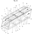
- Fig. 1a shows a view of a heat exchanger 1 according to a first embodiment of the invention.
- the heat exchanger according to Fig. 1a comprises a jacket element 2 and an insert element 3.
- the jacket element 2 is shown as a transparent component, so that the insert element 3 located in the interior of the jacket element 2 is visible.
- the heat exchanger 1 for static mixing and heat exchange according to Fig. 1a thus contains a casing element 2 and an insert element 3, the insert element 3 being arranged in the interior of the casing element 2 in the installed state.
- the jacket element 2 is designed as a hollow body.
- the insert element 3 is in the hollow body recorded.
- the jacket element 2 has a longitudinal axis 4, which extends essentially in the main flow direction of the flowable medium, which flows through the jacket element 2 in the operating state.
- the longitudinal axis 4 runs through the center point of the opening cross section of the casing element.
- the casing element 2 has a rectangular opening cross section. The longitudinal axis 4 thus runs through the intersection of the diagonals of the rectangle.
- the insert element 3 contains a plurality of bar elements 9, 10.
- the bar elements 9 and the bar elements 10 have a different angle of inclination in relation to the longitudinal axis 4.
- the reference numerals 9, 10 designate only one of the web elements of the web element set. All other web elements of the web element groups 41 , 42 , 43 belonging to the web element 9 are preferably arranged essentially parallel to the web element 9 . All other web elements of the web element groups 51 , 52 , 53 belonging to the web element 10 are preferably arranged essentially parallel to the web element 10 .
- Each of the web elements 9 has a first end 13 and a second end 14, the first end 13 and the second end 14 of the web element 9 being connected to the casing element 2 at different locations.
- the bar element 9 contains a bar element channel 11.
- the bar element channel 11 is only represented by a line in the present illustration. Such web element channels are already from EP 2851118 A1 as well as the EP 3489603 A1 known.
- the webs disclosed in these documents are to be regarded as examples of a large number of other possible web shapes.
- the casing element according to the invention can be used for any number, arrangement or shape of the web elements.
- the bar element channel 11 extends from the first end 13 of the bar element 9 to the second end 14 of the bar element 9.
- Each of the web members 10 has a first end 15 and a second end 16, the first end 15 and the second end 16 of the web member 10 being connected to the shell member 2 at different locations.
- the bar element 10 contains a bar element channel 12.
- the bar element channel 12 is only represented by a line in the present illustration. Such web element channels are already from EP 2851118 A1 as well as the EP 3489603 A1 known. The webs disclosed in these documents are to be regarded as examples of a large number of other possible web shapes.
- the bar element channel 12 extends from the first end 15 of the bar element 10 to the second end 16 of the bar element 10.
- a first, second and third bar element group 41, 42, 43 are shown, which consist of bar elements 9.
- a first, second and third group of web elements 51, 52, 53 are shown, which consist of web elements 10.
- each of the crowds of web elements consists of two web elements. This arrangement is to be considered as an example only.
- Each of the sets of web elements can contain more than two web elements.
- Each of the crowds of web elements can have a different number of web elements.
- the number of bar element sets can differ from the illustration Fig. 1a differentiate.
- the bar elements 9 can be arranged crosswise to the bar elements 10 .
- the web elements 9 of one of the first, second or third families of web elements 41, 42, 43, which have a first angle of inclination in relation to the longitudinal axis 4, can crosswise to the web elements 10 of one of the first, second or third families of web elements 51, 52, 53, which have a second Have angle of inclination with respect to the longitudinal axis 4, be arranged.
- Fig. 1b shows the jacket element 2 with the installed insert element 3.
- the jacket element 2 has an inlet opening 5 and an outlet opening 8 for a fluid or fluid mixture which flows through the heat exchanger in the operating state.
- the jacket element 2 is designed as a hollow body, for example as a double jacket, which means that inside the jacket element 2 there are a plurality of chambers. A heat transfer fluid flows through these chambers in the operating state. The flow of the heat transfer fluid is shown in the present representation by dash-dotted lines with two dots between two adjacent dashes.
- the double jacket is formed by an outer shell and an inner shell.
- the outer shell is in Fig. 1b shown transparent to allow a view of the chambers of the casing element 2.
- the jacket element 2 contains at least one inlet 20 and one outlet 30.
- the jacket element 2 according to FIG Fig. 1a or Fig. 1b consists of four chambers.
- the first chamber 21 contains the inlet 20, comprising a tubular element containing an inlet channel for a heat transfer fluid.
- the third chamber 23 contains the outlet 30, which includes a tubular element containing an outlet channel for the heat transfer fluid. Between the first and third chambers 21, 23 are a second and a fourth chamber 22, 24.
- each of the first and third chambers 21, 23 is larger than the second and fourth chamber 22, 24.
- each of the first or third chambers 21, 23 comprise more than 10% each, in particular more than 25% each, of the circumference of the jacket element 2.
- the first chamber 21 extends from the inlet opening 5 to the outlet opening 8 for the fluid which flows through the jacket element 2 in the operating state.
- the first chamber 21 extends over the entire length of the jacket element 2.
- the first chamber 21 forms, according to FIG Fig. 1b shown position from a part of the top surface of the casing element 2 and the side surface adjacent to this top surface.
- the second chamber 22 comprises that part of the top surface of the jacket element 2 which is not occupied by the first chamber 21 .
- a first partition wall 31 is located between the first chamber 21 and the second chamber 22.
- the second chamber 22 extends from the inlet opening 5 to the outlet opening 8 for the fluid which flows through the casing element 2 in the operating state.
- the third chamber 23 extends over the entire length of the casing element 2.
- the third chamber 23 extends from the inlet opening 5 to the outlet opening 8 for the fluid which flows through the casing element 2 in the operating state.
- the third chamber 23 is adjacent to the second chamber 22 .
- the third chamber extends over the side surface adjacent to the top surface, which is opposite the side surface formed by the first chamber 21 .
- the third chamber 23 forms part of the base area of the casing element 2 .
- the second partition wall 32 prevents heat transfer fluid from being able to get from the second chamber 22 directly into the third chamber 23 . In this case, directly means inside the hollow body spanned by the jacket element 2 .
- a fourth chamber 24 adjoins the third chamber 23 and extends over part of the base area of the casing element 2 .
- the fourth chamber 24 is also adjacent to the first chamber 21 .
- the fourth chamber 24 extends over the entire length of the casing element 2 In other words, the fourth chamber 24 extends from the inlet opening 5 to the outlet opening 8 for the fluid which flows through the jacket element 2 in the operating state.
- the first chamber 21 has three inlet openings 40 which are in fluid-conducting connection with channels which run within the web elements 9 which adjoin the first chamber 21 .
- heat transfer fluid can flow through these inlet openings 40 into the web elements 9 , which in the present illustration adjoin the first chamber 21 and extend to the fourth chamber 24 .
- the fourth chamber are located in this Fig. 1b not visible outlet openings, through which the heat transfer fluid can escape from the web element channels and can enter the fourth chamber 24.
- the heat transfer fluid flows through the fourth chamber 24 to the inlet openings, which open into the channels of the parallel bar elements 9 and into the channels of the bar elements 10 arranged crosswise to the bar elements 9, which extend from the fourth chamber 24 to the second chamber 22.
- the heat transfer fluid exits through six outlet openings 50 from the channels of the bar elements 9, 10 and into the second chamber 22.
- the outlet openings 50 are in Fig. 1a and Fig. 1b painted black to distinguish it from the entry openings.
- the heat transfer fluid flows through the second chamber 22 to the inlet openings that open into the channels of the bar elements 10 that extend from the second chamber 22 to the third chamber 23 .
- the channels of a part of the bar elements 10 in the present exemplary embodiment three bar elements 10 , thus open into outlet openings which open into the third chamber 23 .
- the heat transfer fluid enters the third chamber 23 via these outlet openings, which are not visible in the present illustration, and can leave the jacket element 2 via the outlet 30 .
- Part of the heat transfer fluid also flows through the chamber part of the third chamber 23 that is adjacent to the right-hand side surface. Heat exchange between the heat transfer fluid and the fluid can thus take place both via the walls of the web elements and via the chamber walls of the first to fourth chambers 21, 22, 23, 24 take place.
- FIG. 1c shows a section through a heat exchanger 1 according to Fig. 1a or Fig. 1b .
- the sectional plane is aligned normal to the direction of flow of the fluid and lies between the inlet opening 5 and the inlet 20.
- the casing element 2 comprises four chambers 21, 22, 23, 24.
- the chambers are defined by the inner casing element wall, the outer casing element wall and the partition walls 31, 32, 33, 34 extending between the inner shell member wall and the outer shell member wall.
- the first chamber 21 is in fluid communication with the inlet 20 and via the web element channels 11 (only one of which is shown in this illustration) with the fourth chamber 24, so that in the operating state the heat transfer fluid can flow from the inlet 20 into the first chamber 21 and can reach the fourth chamber 24 via the web element channels 11 .
- the web elements 9 form a fluid-tight connection with the inner casing element wall, which forms one of the boundaries of the first chamber 21 .
- the web elements 9 form a fluid-tight connection with the inner casing element wall, which forms one of the boundaries of the fourth chamber 24 .
- the heat transfer fluid can thus not come into contact with the fluid flowing between the web elements 9, 10.
- the heat exchange between the fluid and the heat transfer fluid thus takes place via the inner jacket element walls of the jacket element 2 and via the web element walls of the web elements 9, 10 of the insert element 3.
- the fourth partition wall 34 could be omitted.
- the heat transfer fluid can flow both through the web element channels 11 and through the chamber formed in the jacket element.
- the first and fourth chambers instead of the first and fourth chambers, only a single chamber would be present.
- the fourth partition wall 34 could be designed as an intermediate wall that contains recesses or openings for the heat transfer fluid that, according to this exemplary embodiment, can flow from the first chamber 21 into the fourth chamber 24 .
- the inner shell element wall of the fourth chamber 24 contains a plurality of outlet openings 50 for the bar element channels 11 of the bar elements 9 which are in communication with the first chamber 21 .
- the inner shell member wall of the fourth chamber 24 includes a plurality of entry openings 40 for the web member channels 12 of the web members 10 which communicate between the fourth chamber 24 and the second Form chamber 22.
- the inner casing element wall of the fourth chamber 24 contains a plurality of entry openings 40 for the bar element channels 11 of the bar elements 9 which form the connection between the fourth chamber 24 and the second chamber 22 .
- the fourth chamber 24 thus contains a plurality of inlet openings 40 and a plurality of outlet openings 50.
- the inner shell element wall of the second chamber 22 contains a plurality of outlet openings 50 for the bar element channels 11 of the bar elements 9 which are in communication with the fourth chamber 24 .
- the inner casing element wall of the second chamber 22 contains a plurality of outlet openings 50 for the bar element channels 11 of the bar elements 9 and the bar element channels 12 of the bar elements 10 which form the connection between the fourth chamber 24 and the second chamber 22 .
- the inner shell element wall of the second chamber 22 contains a plurality of entry openings 40 for the web element channels 12 of the web elements 10 which form the connection between the second chamber 22 and the third chamber 23 .
- the second chamber 22 thus contains a plurality of inlet openings 40 and a plurality of outlet openings 50.
- the inner shell member wall of the third chamber 23 contains a plurality of entry openings 40 for the web member passages 12 of the web members 10 communicating with the second chamber 22 .
- the outer shell element wall of the third chamber 23 contains at least one outlet opening 50 for the outlet channel of the outlet 30.
- the third chamber 23 thus contains a plurality of outlet openings 50 and at least one inlet opening 40.
- Fig. 1d shows a variant of a heat exchanger 1 according to FIG Figures 1a to 1c illustrated embodiment.
- this heat exchanger is therefore on the description of the Figures 1a to 1c referred to, insofar as it is applicable to this variant.
- the casing element 2 comprises four chambers 21, 22, 23, 24.
- the chambers are delimited by the inner casing element wall, the outer casing element wall and the partition walls 31, 32, 33, 34 which extend between the inner casing element wall and the outer casing element wall.
- the first chamber 21 is delimited by the inner casing element wall, the outer casing element wall and the first partition wall 31 and the second partition wall 32 and two side walls, not shown, which are in the area of the inlet opening 5 (see Fig. 1a or Fig. 1b ) or the Outlet opening 8 can be.
- the first chamber 21 is in fluid communication with the inlet 20 and via the bar element channels 11 (only one of which is shown in this illustration) and the bar element channels 12 with the second chamber 22, so that in the operating state the heat transfer fluid from the inlet 20 into the first Chamber 21 can flow and can reach the second chamber 22 via the web element channels 12 .
- the web elements 9 form a fluid-tight connection with the inner casing element wall, which forms one of the boundaries of the first chamber 21 .
- the web elements 9 form a fluid-tight connection with the inner casing element wall, which forms one of the boundaries of the first chamber 21 .
- the heat transfer fluid can thus not come into contact with the fluid flowing between the web elements 9, 10.
- the heat exchange between the fluid and the heat transfer fluid thus takes place via the inner jacket element walls of the jacket element 2 and via the web element walls of the web elements 9, 10 of the insert element 3.
- the first chamber 21 there is an intermediate wall between the web elements 9, whose central axes span a common plane, and the web elements 10, whose central axes span a common plane.
- the intermediate wall can be flowed around or through by the heat transfer fluid if it contains recesses or openings.
- the heat transfer fluid can flow both through the web element channels 11, 12 and through the first chamber 21 formed in the jacket element.
- the inner shell member wall of the second chamber 22 includes a plurality of exit ports 50 for the web member channels 12 of the web members 10 communicating with the first chamber 21.
- the inner casing element wall of the second chamber 22 contains a plurality of entry openings 40 for the bar element channels 11 of the bar elements 9 which form the connection between the second chamber 22 and the third chamber 23 .
- the second chamber 22 thus contains a plurality of inlet openings 40 and a plurality of outlet openings 50.
- the inner shell element wall of the third chamber 23 contains a plurality of outlet openings 50 for the bar element channels 11 of the bar elements 9 which are in connection with the fourth chamber 24 .
- the inner casing element wall of the second chamber 22 contains a plurality of outlet openings 50 for the bar element channels 11 of the bar elements 9 which form the connection between the second chamber 22 and the third chamber 23 .
- the inner shell element wall of the third chamber 23 contains a plurality of entry openings 40 for the web element channels 12 of the web elements 10 which form the connection between the third chamber 23 and the fourth chamber 24 .
- the third chamber 23 thus contains a plurality of inlet openings 40 and a plurality of outlet openings 50.
- the third chamber 23 also contains a partition 39, which the heat transfer fluid can flow around or through if it has openings or recesses.
- the inner shell element wall of the fourth chamber 24 contains a plurality of outlet openings 50 for the web element channels 12 of the web elements 10 which are in communication with the third chamber 23 .
- the outer casing element wall of the fourth chamber 24 contains at least one outlet opening 50 for the outlet channel of the outlet 30.
- the fourth chamber 24 thus contains a plurality of outlet openings 50 and at least one inlet opening 40.
- the first chamber 21, the second chamber 22 and the third chamber 23 contain partitions 39.
- the partitions 39 do not extend over the entire height of the chamber and/or not over the total length of the chamber.
- the use of the intermediate walls 39 enables the flow of the heat transfer fluid within the chambers to be deflected, according to the present example within the first, second and third chamber.
- the partition walls 39 shown are, of course, only one of several possible arrangements of partition walls 39; the partition walls 39 can therefore vary in length, height, position and number from the Fig. 1d selected representation.
- Fig. 1e shows a variant of a heat exchanger 1 according to FIG Figures 1a to 1d illustrated embodiment.
- the number of web elements 9, 10 located in the fluid channel is greater in comparison to the previous exemplary embodiments.
- the number of web elements 9, 10 can thus differ from that in Figures 1a to 1c number shown differ.
- the number of chambers of the casing element 2 can also differ from that in the Figures 1a to 1c number shown differ.
- Both the number of web elements 9, 10 and the number of chambers of the casing element 2 is to be regarded as an exemplary embodiment.
- a heat exchanger 1 with a number of web elements 9, 10 and/or a number of chambers that differs from the number shown is therefore expressly included within the scope of the claims.
- the jacket element 2 comprises five chambers 21, 22, 23, 24, 25.
- the chambers are defined by the inner jacket element wall, the outer jacket element wall and the Partitions 31, 32, 33, 34, 35 extending between the inner shell member wall and the outer shell member wall.
- the first chamber 21 is delimited by the inner casing element wall, the outer casing element wall and the first partition wall 31 and the fifth partition wall 35 and two side walls, not shown, which are in the area of the inlet opening 5 (see Fig. 1a or Fig. 1b ) or the outlet opening 8.
- the first chamber 21 is in fluid communication with the inlet 20 and via the web element channels 11, 12 (only one of which is shown in this illustration) with the second chamber 22, so that in the operating state the heat transfer fluid flows from the inlet 20 into the first chamber 21 can flow and can reach the second chamber 22 via the web element channels 11 , 12 .
- the web elements 9 form a fluid-tight connection with the inner casing element wall, which forms one of the boundaries of the first chamber 21 .
- the web elements 9 form a fluid-tight connection with the inner casing element wall, which forms one of the boundaries of the second chamber 22 .
- the web elements 10 form a fluid-tight connection with the inner casing element wall, which forms one of the boundaries of the first chamber 21 .
- the bar elements 10 form the second end 16 of which forms a fluid-tight connection with the inner shell element wall which forms one of the boundaries of the second chamber 22 .
- the heat transfer fluid can thus not come into contact with the fluid flowing between the web elements 9, 10. The heat exchange between the fluid and the heat transfer fluid thus takes place via the inner jacket element walls of the jacket element 2 and via the web element walls of the web elements 9, 10 of the insert element 3.
- the inner casing element wall of the second chamber 22 contains a plurality of outlet openings 50 for the bar element channels 10,11 of the bar elements 9,10 which are in connection with the first chamber 21.
- the inner shell element wall of the second chamber 22 contains a plurality of inlet openings 40 for the web element channels 11,12 of the web elements 9,10, which form the connection between the second chamber 22 and the fourth chamber 24.
- the second chamber 22 thus contains a plurality of inlet openings 40 and a plurality of outlet openings 50.
- the inner casing element wall of the fourth chamber 24 contains a plurality of outlet openings 50 for the web element channels 10,11 of the web elements 9,10 which are in connection with the second chamber 22.
- the inner shell element wall of the fourth chamber 24 contains a plurality of inlet openings 40 for the bar element channels 11, 12 of the bar elements 9,10 which form the connection between the fourth chamber 24 and the third chamber 23.
- the fourth chamber 24 thus contains a plurality of inlet openings 40 and a plurality of outlet openings 50.
- the inner casing element wall of the third chamber 23 contains a plurality of outlet openings 50 for the bar element channels 11, 12 of the bar elements 9,10 which are in connection with the fourth chamber 24.
- the inner shell element wall of the third chamber 23 contains a plurality of inlet openings 40 for the bar element channels 11,12 of the bar elements 9,10, which form the connection between the third chamber 23 and the fifth chamber 25.
- the third chamber 23 thus contains a plurality of inlet openings 40 and a plurality of outlet openings 50.
- the inner casing element wall of the fifth chamber 25 contains a plurality of outlet openings 50 for the web element channels 11,12 of the web elements 9,10 which are in connection with the third chamber 23.
- the outer shell element wall of the fifth chamber 25 contains at least one inlet opening 40 for the outlet channel of the outlet 30.
- the fifth chamber 25 thus contains a plurality of outlet openings 50 and at least one inlet opening 40.
- 1f shows a variant of a heat exchanger 1 according to FIG Figures 1a to 1e illustrated embodiment.
- this heat exchanger are therefore the same reference numerals as for the description of the Figures 1a to 1c used where the reference numerals refer to the same or equivalent elements of the heat exchanger.
- 1f thus shows a section through a variant of the heat exchanger 1 according to FIG Fig. 1a or Fig. 1b .
- the sectional plane is aligned normal to the direction of flow of the fluid and lies between the inlet opening 5 and the inlet 20.
- the casing element 2 comprises six chambers 21, 22, 23, 24, 25, 26.
- the chambers are defined by the inner casing element wall, the outer casing element wall and the partitions 31, 32, 33, 34, 35, 36 extending between the inner shell member wall and the outer shell member wall.
- the first chamber 21 is delimited by the inner casing element wall, the outer casing element wall and the first partition wall 31 and the second partition wall 32 and two side walls, not shown, which are in the area of the inlet opening 5 and the outlet opening 8 (see Fig Fig. 1a or Fig. 1b ).
- the first chamber 21 is in fluid communication with the inlet 20 and via the web element channels 11 (only one of which is shown in this illustration) with the second chamber 22, so that in the operating state the heat transfer fluid can flow from the inlet 20 into the first chamber 21 and can reach the second chamber 22 via the web element channels 11 .
- the web elements 9 form a fluid-tight connection with the inner casing element wall, which forms one of the boundaries of the first chamber 21 .
- the web elements 9 form a fluid-tight connection with the inner casing element wall, which forms one of the boundaries of the second chamber 22 .
- the heat transfer fluid can thus not come into contact with the fluid flowing between the web elements 9, 10.
- the heat exchange between the fluid and the heat transfer fluid thus takes place via the inner jacket element walls of the jacket element 2 and via the web element walls of the web elements 9, 10 of the insert element 3.
- the inner shell element wall of the second chamber 22 contains a plurality of outlet openings 50 for the web element channels 11 of the web elements 9, which in connection related to the first chamber 21.
- the inner shell element wall of the second chamber 22 contains a plurality of entry openings 40 for the web element channels 12 of the web elements 10 which form the connection between the second chamber 22 and the third chamber 23 .
- the second chamber 22 thus contains a plurality of inlet openings 40 and a plurality of outlet openings 50.
- the inner shell element wall of the third chamber 23 contains a plurality of entry openings 40 for the web element channels 12 of the web elements 10 which form the connection between the third chamber 23 and the second chamber 22 .
- the outer shell element wall of the third chamber 23 contains at least one outlet opening 50 for the outlet channel of the outlet 30.
- the third chamber 23 thus contains a plurality of inlet openings 40 and at least one outlet opening 50.
- the fourth chamber 24 is in fluid communication with a further inlet 20 and via the web element channels 11 (only one of which is shown in this illustration) with the fifth chamber 25, so that in the operating state the heat transfer fluid flows from the inlet 20 into the fourth chamber 24 and can reach the fifth chamber 25 via the web element channels 11 .
- the inlet openings and outlet openings are in 1f not designated, since they correspond to the inlet openings and outlet openings for the first and second chambers 21, 22, respectively, described earlier.
- the inner casing element wall of the fourth chamber 24 contains a plurality of outlet openings 50 for the bar element channels 11 of the bar elements 9 which are in connection with the fifth chamber 25 .
- the fourth chamber 24 thus contains at least one inlet opening 40 and a plurality of outlet openings 50.
- the inner casing element wall of the fifth chamber 25 contains a plurality of outlet openings 50 for the bar element channels 11 of the bar elements 9 which form the connection between the fifth chamber 25 and the fourth chamber 24 .
- the inner shell member wall of the fifth chamber 25 contains a plurality of entry openings 40 for the web member passages 12 of the web members 10 communicating with the sixth chamber 26 .
- the fifth chamber 25 thus contains a plurality of inlet openings 40 and a plurality of outlet openings 50.
- the inner shell element wall of the sixth chamber 26 contains a plurality of outlet openings 50 for the web element channels 12 of the web elements 10 which are in communication with the fifth chamber 25.
- the outer shell element wall of the sixth chamber 26 contains at least one outlet opening 50 for a further outlet channel of the outlet 30.
- the sixth chamber 26 thus contains a plurality of inlet openings 40 and at least one outlet opening 50.
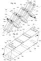
- FIG 2a shows a view of a heat exchanger 100 according to a second embodiment of the invention.
- the heat exchanger 100 according to Figure 2a includes a shell member 102 and an insert member 103.
- the shell member is not fully shown, only the chambers of the shell member 102 are shown, the entire shell member 102 is off Figure 2b evident.
- the jacket element 102 is shown as a transparent component, so that the insert element 103 located in the interior of the jacket element 102 is visible.
- the heat exchanger 100 for static mixing and heat exchange according to Figure 2a thus contains a jacket element 102 and an insert element 103, wherein the insert element 103 is arranged in the installed state inside the jacket element 102.
- the jacket element 102 is partially designed as a hollow body.
- the insert element 103 is accommodated in the casing element.
- the jacket element 102 has a longitudinal axis 104, which extends essentially in the main flow direction of the flowable medium or fluid or fluid mixture, which flows through the jacket element 102 in the operating state.
- the longitudinal axis 104 runs through the center point of the opening cross-section of the casing element.
- the casing element 102 has a rectangular opening cross section.
- the longitudinal axis 104 thus runs through the point of intersection of the diagonals of the rectangle in the same way as in FIG Figure 2b arrangement shown.
- the insert element 103 contains a plurality of bar elements 109, 110.
- the bar elements 109 and the bar elements 110 have a different angle of inclination in relation to the longitudinal axis 104.
- the reference numerals 109, 110 designate only one of the web elements of the web element set. All other bar elements belonging to the bar element 109 groups of bar elements are arranged parallel to the bar element 109 . All others Web elements of the web element sets belonging to the web element 110 are arranged parallel to the web element 110 .
- Each of the web members 109 has a first end 113 and a second end 114, with the first end 113 and the second end 114 of the web member 109 being connected to the shell member 102 at different locations.
- the web element 109 contains a web element channel 111. In the present illustration, only the inlet opening of the web element channel 111 is shown. Such web element channels are already from EP 2851118 A1 as well as the EP 3489603 A1 known.
- the bar elements disclosed in these documents are to be regarded as examples of a large number of other possible bar shapes.
- the jacket element 102 according to the invention can be used for any number, arrangement or shape of the web elements.
- the web element channel 111 extends from the first end 113 of the web element 109 to the second end 114 of the web element 109.
- Each of the web members 110 has a first end 115 and a second end 116, with the first end 115 and the second end 116 of the web member 110 being connected to the shell member 102 at different locations.
- the bar element 110 contains a bar element channel 112. In the present illustration, only the inlet opening of the bar element channel 112 is shown. Such web element channels are already from EP 2851118 A1 as well as the EP 3489603 A1 known. The bar elements disclosed in these documents are to be regarded as examples of a large number of other possible bar shapes.
- the web member channel 112 extends from the first end 115 of the web member 110 to the second end 116 of the web member 110.
- the jacket element 102 is partially designed as a hollow body.
- the insert element 103 is accommodated in the casing element.
- the jacket element 102 has a longitudinal axis 104, which extends essentially in the main flow direction of the flowable medium or fluid or fluid mixture, which flows through the jacket element 102 in the operating state.
- the longitudinal axis 104 runs through the center point of the opening cross-section of the casing element and is in Figure 2b more visible.
- the casing element 102 has a rectangular opening cross section. The longitudinal axis 104 thus runs through the intersection of the diagonals of the rectangle.
- a first, second and third set of web elements are shown, which consist of web elements 109. Furthermore, one first, second and third set of web elements are shown, which consist of web elements 110 .
- each of the crowds of web elements consists of two web elements. This arrangement is to be considered as an example only.
- Each of the sets of web elements can contain more than two web elements.
- Each of the crowds of web elements can have a different number of web elements. The number of bar element sets can differ from the illustration Figure 2a differentiate.
- FIG 2b shows the jacket element 102 without the insert element 103 located therein.
- the jacket element 102 has an inlet opening 105 and an outlet opening 108 for a fluid, free-flowing medium or fluid mixture, which flows through the heat exchanger in the operating state.
- the jacket element 102 is at least partially designed as a hollow body, for example as a double jacket, that is to say the jacket element 102 contains a plurality of chambers. A heat transfer fluid flows through these chambers in the operating state.
- the flow of the heat transfer fluid is in Figure 2a represented by dash-dot lines with two dots between two adjacent dashes or represented as dashed lines.
- the jacket element is formed by an outer shell and an inner shell.
- the outer and inner shell is in Figure 2a shown transparent only for the chambers in order to show the position of the chambers of the casing element 102 in the installed state.
- the jacket element 102 according to Figure 2b contains at least two inlets 120 and two outlets 130.
- the jacket element 102 according to 2a or 2b includes eight chambers.
- the first chamber 121 contains the inlet 120, comprising a tubular element containing an inlet channel for a heat transfer fluid.
- the second chamber 122 contains the further inlet 120, comprising a tubular element containing a further inlet channel for the heat transfer fluid.
- Each of the third, fourth, fifth, sixth chambers 123, 124, 125, 126 contains inlet openings and outlet openings of the web elements 109, 110.
- the seventh chamber 127 contains the outlet 130, which comprises a tubular element containing an outlet channel for the heat transfer fluid.
- the eighth chamber 128 contains a further outlet 130, which includes a tubular element containing an outlet channel for the heat transfer fluid.
- each of the third, fourth, fifth, sixth chambers 123, 124, 125, 126 is larger than the first, second, seventh and eighth chambers 121, 122, 127, 128.
- the width of each of the third, fourth , fifth, sixth chambers 123, 124, 125, 126 comprise 10% up to and including 25% of the circumference of the jacket element 102. The width of these chambers is measured in a plane that is normal to the longitudinal axis 104 .
- the first chamber 121 does not extend from the inlet opening 105 to the outlet opening 108 for the fluid which flows through the casing element 102 in the operating state.
- the first chamber 121 is in fluid-conducting connection only with the inlet openings 140 of the web elements 110 belonging to the set of web elements 151 and the inlet 120 .
- the first chamber 121 does not extend over the entire length or width of the casing element 102.
- FIG Figure 2b position shown from a part of the top surface of the jacket member 102.
- the second chamber 122 comprises part of the bottom surface of the casing element 102.
- the second chamber 122 is in fluid-conducting connection only with the inlet openings 140 of the web elements 109 belonging to the web element set 141 and the inlet 120.
- the second chamber 122 does not extend over the entire length or width of the casing element 102. According to in Figure 2b position shown from a part of the bottom surface of the jacket member 102.
- the third chamber 123 is arranged on the top surface of the casing element 102 .
- the third chamber 123 contains the outlet openings 150 of the web elements 109 belonging to the web element crowd 141 and the inlet openings 140 of the web elements 110 belonging to the web element crowd 152 .
- All inlet openings 140 are in Figure 2a shown as circular openings. This depiction of the entry openings 140 as circular openings is to be considered as an example only and not as limiting to the shape of the opening cross-section.
- the opening cross section of the inlet openings can deviate from the circular shape; in particular, rectangular, polygonal, elliptical or other opening cross sections are possible.
- All outlet openings 150 are in Figure 2a shown as circular openings. In order to be able to easily distinguish the outlet openings 150 from the inlet openings 140, the opening cross sections were blackened.
- This depiction of the exit openings 150 as circular openings is only to be regarded as an example and not as limiting to the shape of the opening cross-section.
- the opening cross section of the outlet openings 150 can deviate from the circular shape; in particular, rectangular, polygonal, elliptical or other opening cross sections are possible.
- the fourth chamber 124 is arranged on the bottom surface of the casing element 102 .
- the fourth chamber 124 contains the inlet openings 140 of the web elements 109 belonging to the web element crowd 142 and the outlet openings 150 of the web elements 110 belonging to the web element crowd 151 .
- the fifth chamber 125 is arranged on the top surface of the casing element 102 .
- the fifth chamber 125 contains the outlet openings 150 of the web elements 109 belonging to the web element crowd 142 and the inlet openings 140 of the web elements 110 belonging to the web element crowd 153 .
- the sixth chamber 126 is arranged on the bottom surface of the casing element 102 .
- the sixth chamber 126 contains the inlet openings 140 of the web elements 109 belonging to the web element crowd 143 and the outlet openings 150 of the web elements 110 belonging to the web element crowd 152 .
- the seventh chamber 127 is in fluid-conducting connection only with the outlet openings 150 of the web elements 109 belonging to the set of web elements 143 and the outlet 130 . According to this exemplary embodiment, the seventh chamber 127 does not extend over the entire length or width of the jacket element 102.
- the seventh chamber 127 forms, according to FIG Figure 2b position shown from a part of the top surface of the jacket member 102.
- the eighth chamber 128 is in fluid-conducting connection only with the outlet openings 150 of the web elements 110 belonging to the set of web elements 153 and the outlet 130 . According to this exemplary embodiment, the eighth chamber 128 does not extend over the entire length or width of the casing element 102. According to the Figure 2b position shown from a part of the bottom surface of the jacket member 102.
- the heat transfer fluid is fed via an inlet 120 through the first chamber 121 to the web elements 110 of the web element family 151 .
- the heat transfer fluid is also supplied via an inlet 120 through the second chamber 122 to the web elements 109 of the web element array 141 .
- the first chamber 121 and the second chamber 122 therefore have the function of distributing the heat transfer fluid to the corresponding inlet openings 140 of the corresponding bar element channels 111, 112 of the bar elements 109, 110.
- the web element channels 111, 112, which run within the web elements 109, 110, are not shown; their course can be seen from the flow of the heat transfer medium, which is represented by dash-dotted lines with two dots between two adjacent dashes or dashed lines.
- the heat transfer fluid which flows from the first chamber 121 into the web element channels 112 of the web elements 110 of the web element family 151, passes through outlet openings 150 into the fourth chamber 124 and flows from there into the inlet openings 140 of the web element channels 111 of the web element family 142.
- the outlet openings 150 of the web element channels 112 of the web elements 110 of the web element family 151 and the inlet openings 140 of the web element channels 111 of the web elements 109 of the web element family 142 are located in the fourth chamber 124.
- the heat transfer fluid can flow through the outlet openings 150 into the inlet openings and reaches the web element channels 111 of the bar elements 109 of the bar element set 142.
- the outlet openings 150 of the web element channels 111 of the web elements 109 of the web element family 142 and the inlet openings 140 of the web element channels 112 of the web elements 110 of the web element family 153 are located in the fifth chamber 125.
- the heat transfer fluid can flow through the outlet openings 150 into the inlet openings and reaches the web element channels 112 of the bar elements 110 of the bar element set 153.
- the outlet openings of the web element channels 112 of the web elements 110 of the web element family 153 are located in the eighth chamber 128.
- the eighth chamber 128 contains an outlet opening 150 for a drain 130.
- the heat transfer fluid is also fed via an inlet 120 through the second chamber 122 to the web elements 109 of the web element family 141 .
- the heat transfer fluid which flows from the second chamber 122 into the web element channels 111 of the web elements 109 of the web element family 141, passes through outlet openings 150 into the third chamber 123 and flows from there into the inlet openings 140 of the web element channels 112 of the web element family 152.
- the outlet openings 150 of the bar element channels 111 of the bar elements 109 of the bar element crowd 141 and the inlet openings 140 of the bar element channels 112 of the bar elements 110 of the bar element crowd 152 are located in the third chamber 123.
- the Heat transfer fluid can flow through the outlet openings 150 into the inlet openings and gets into the bar element channels 112 of the bar elements 110 of the bar element set 152.
- the outlet openings 150 of the web element channels 112 of the web elements 110 of the web element family 152 and the inlet openings 140 of the web element channels 111 of the web elements 109 of the web element family 143 are located in the sixth chamber 126.
- the heat transfer fluid can flow through the outlet openings 150 into the inlet openings and reaches the web element channels 111 of the bar elements 109 of the bar element set 143.
- the outlet openings of the web element channels 111 of the web elements 109 of the web element family 143 are located in the seventh chamber 127.
- the seventh chamber 127 contains an outlet opening 150 for a drain 130.
- the heat transfer fluid thus flows crosswise in the opposite direction to the fluid whose main flow direction runs in the direction of the longitudinal axis 104 and is indicated by an arrow with a double line.
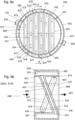
- FIG 3a shows a view of a heat exchanger 200 according to a third embodiment of the invention.
- the heat exchanger 200 according to Figure 3a includes a shell member 202 and an insert member 203.
- the shell member is not fully shown, only the chambers of the shell member 202 are shown, the entire shell member 202 is off Figure 3b apparent.
- the jacket element 202 is shown as a transparent component, so that the insert element 203 located in the interior of the jacket element 202 is visible.
- the heat exchanger 200 for static mixing and heat exchange according to Figure 3a thus contains a casing element 202 and an insert element 203, the insert element 203 being arranged in the interior of the casing element 202 in the installed state.
- the jacket element 202 is partially designed as a hollow body.
- the insert element 203 is accommodated in the shell element.
- the jacket element 202 has a longitudinal axis 204, which extends essentially in the main flow direction of the flowable medium or fluid or fluid mixture, which flows through the jacket element 202 in the operating state.
- the longitudinal axis 204 runs through the center point of the opening cross-section of the shell element and is in Figure 3b more visible.
- the casing element 202 has a rectangular opening cross section. The longitudinal axis 204 thus runs through the intersection of the diagonals of the rectangle.
- the insert element 203 contains a plurality of bar elements 209, 210.
- the bar elements 209 and the bar elements 210 have a different angle of inclination in relation to the longitudinal axis 204.
- the reference numerals 209, 210 designate only one of the web elements of the web element set. All other web elements of the web element groups belonging to the web element 209 are arranged parallel to the web element 209 . All other bar elements belonging to the bar element 210 groups of bar elements are arranged parallel to the bar element 210 .
- Each of the web members 209 has a first end 213 and a second end 214, with the first end 213 and the second end 214 of the web member 209 being connected to the shell member 202 at different locations.
- the web element 209 contains a web element channel 211. Only the inlet opening of the web element channel 211 is shown in the present illustration. Such web element channels are already from EP 2851118 A1 as well as the EP 3489603 A1 known.
- the bar elements disclosed in these documents are to be regarded as examples of a large number of other possible bar shapes.
- the jacket element 202 according to the invention can be used for any number, arrangement or shape of the web elements.
- the web element channel 211 extends from the first end 213 of the web element 209 to the second end 214 of the web element 209.
- Each of the web members 210 has a first end 215 and a second end 216, with the first end 215 and the second end 216 of the web member 210 being connected to the shell member 202 at different locations.
- the bar element 210 contains a bar element channel 212. Only the outlet opening of the bar element channel 212 is shown in the present illustration. Such web element channels are already from EP 2851118 A1 as well as the EP 3489603 A1 known. The bar elements disclosed in these documents are to be regarded as examples of a large number of other possible bar shapes.
- the web member channel 212 extends from the first end 215 of the web member 210 to the second end 216 of the web member 210.
- a first, second and third set of web elements are shown, which consist of web elements 209. Furthermore, a first, second and third set of web elements are shown, which consist of web elements 210 .
- each of the crowds of web elements consists of two web elements. This arrangement is to be considered as an example only.
- Each of the Web element families can contain more than two web elements.
- Each of the crowds of web elements can have a different number of web elements. The number of bar element sets can differ from the illustration Figure 3a differentiate.
- Figure 3b shows the jacket element 202 without the insert element 203 located therein.
- the jacket element 202 has an inlet opening 205 and an outlet opening 208 for a fluid, free-flowing medium or fluid mixture, which flows through the heat exchanger in the operating state.
- the direction of flow of the fluid is indicated by two arrows, which are represented by double lines.
- the jacket element 202 is at least partially designed as a hollow body, for example as a double jacket, that is to say the jacket element 202 contains a plurality of chambers.
- a heat transfer fluid flows through these chambers in the operating state.
- the flow of the heat transfer fluid is in Figure 3a represented by dash-dot lines with two dots between two adjacent dashes.
- the jacket element is formed by an outer shell and an inner shell.
- the outer and inner shell is in Figure 3a shown transparent only for the chambers to show the position of the chambers of the jacket member 202 in the installed state.
- the jacket element 202 according to Figure 3b contains at least two inlets 220 and two outlets 230.
- the jacket element 202 according to 3a or 3b includes seven chambers.
- the first chamber 221 contains an outlet 230 comprising a tubular element containing an outlet channel for a heat transfer fluid.
- the second chamber 222 contains an inlet 220 comprising a tubular element containing a further inlet channel for the heat transfer fluid.
- Each of the third, fourth, fifth chambers 223, 224, 225 contains inlet openings and outlet openings of the web elements 209, 210.
- the sixth chamber 226 contains a further inlet 220, which includes a tubular element containing an inlet channel for the heat transfer fluid.
- the seventh chamber 227 contains a further outlet 230, which includes a tubular element containing an outlet channel for the heat transfer fluid.
- each of the third, fourth, fifth chambers 223, 224, 225 is larger than the first, second, sixth and seventh chambers 221, 222, 226, 227.
- the width of each of the third, fourth, fifth chambers 223 , 224, 225 comprise 10% up to and including 25% of the circumference of the shell element 202. The width of these chambers is measured in a plane that is normal to the longitudinal axis 204 .
- the first chamber 221 does not extend from the inlet opening 205 to the outlet opening 208 for the fluid which flows through the casing element 202 in the operating state.
- the first chamber 221 is in fluid-conducting connection only with the outlet openings 250 of the web elements 210 belonging to the set of web elements 251 and the outlet 230 .
- the first chamber 221 does not extend over the entire length or width of the casing element 202.
- the second chamber 222 comprises part of the bottom surface of the casing element 202.
- the second chamber 222 is in fluid-conducting connection with the inlet openings 240 of the web elements 209 belonging to the web element family 241 and the inlet 220.
- the second chamber 222 does not extend over the entire length or width of the casing element 202. According to in Figure 3b position shown from a portion of the bottom surface of the shell member 202.
- the third chamber 223 is arranged on the top surface of the casing element 202 .
- the third chamber 223 contains the outlet openings 250 of the web elements 209 belonging to the web element crowd 241 and the inlet openings 240 of the web elements 209 belonging to the web element crowd 242 .
- the third chamber 223 contains the outlet openings 250 of the web elements 210 belonging to the web element crowd 252 and the inlet openings 240 of the web elements 210 belonging to the web element crowd 253 .
- the fourth chamber 224 is arranged on the bottom surface of the casing element 202 .
- the fourth chamber 224 contains the inlet openings 240 of the bar element channels 212 of the bar elements 210 belonging to the bar element crowd 251 and the outlet openings 250 of the bar element channels 211 of the bar elements 209 belonging to the bar element crowd 242 .
- the fifth chamber 225 is arranged on the bottom surface of the casing element 202 .
- the fifth chamber 225 contains the inlet openings 240 of the bar element channels 212 of the bar elements 210 belonging to the bar element crowd 252 and the outlet openings 250 of the bar element channels 211 of the bar elements 209 belonging to the bar element crowd 243 .
- the sixth chamber 226 is in fluid-conducting connection only with the inlet openings 240 of the web elements 209 belonging to the set of web elements 243 and the inlet 220 . According to this exemplary embodiment, the sixth chamber 226 does not extend over the entire length or width of the casing element 202. According to the Figure 3b shown position from a part of the top surface of the jacket member 202.
- the seventh chamber 227 is in fluid-conducting connection only with the outlet openings 250 of the web elements 210 belonging to the set of web elements 253 and the outlet 230 . According to this exemplary embodiment, the seventh chamber 227 does not extend over the entire length or width of the casing element 202. According to the Figure 3b position shown from a portion of the bottom surface of the shell member 202.
- the heat transfer fluid is supplied via an inlet 220 through the sixth chamber 226 to the web elements 209 of the web element family 243 .
- the heat transfer fluid is also supplied via an inlet 220 through the second chamber 222 to the web elements 209 of the web element array 241 .
- the sixth chamber 226 and the second chamber 222 therefore have the function of distributing the heat transfer fluid to the corresponding inlet openings 240 of the corresponding bar element channels 211 of the bar elements 209 .
- the web element channels 211, 212, which run within the web elements 209, 210, are not shown; their course can be seen from the flow course of the heat transfer medium, which is represented by dash-dotted lines with two dots between two adjacent dashes.
- the heat transfer fluid which flows from the second chamber 222 into the web element channels 211 of the web elements 209 of the web element family 241, passes through outlet openings 250 into the third chamber 223 and flows from there into the inlet openings 240 of the web element channels 211 of the web element family 242.
- the heat transfer fluid which from fifth chamber 225 into the web element channels 212 of the web elements 210 of the web element family 252, passes through outlet openings 250 into the third chamber 223 and flows from there into the inlet openings 240 of the web element channels 212 of the web element family 252.
- the heat transfer fluid flows through the corresponding inlet openings 240 either into the web element channels 211 of the web elements 209 of the web element family 242 to the fourth chamber 224 or in the web element channels 212 of the web elements 210 of the web element family 253 to the seventh chamber 227.
- the outlet openings 250 of the web element channels 211 of the web elements 209 of the web element family 242 and the inlet openings 240 of the web element channels 212 of the web elements 210 of the web element family 251 are located in the fourth chamber 224.
- the heat transfer fluid can flow through the outlet openings 250 into the inlet openings 240 and gets into the web element channels 212 of the bar elements 210 of the bar element family 251 to the first chamber 221.
- the heat transfer fluid coming from the bar element channels 212 of the bar elements 210 of the bar element family 251 is collected and fed to the outlet 230 in order to leave the heat exchanger.
- the outlet openings 250 of the web element channels 211 of the web elements 209 of the web element family 243 and the inlet openings 240 of the web element channels 212 of the web elements 210 of the web element family 252 are located in the fifth chamber 225.
- the heat transfer fluid can flow through the outlet openings 250 into the inlet openings 240 and gets into the web element channels 212 of the web elements 210 of the web element family 252 and reaches the third chamber 223.
- the outlet openings of the web element channels 212 of the web elements 210 of the web element family 252 are located in the third chamber 223.
- the heat transfer fluid which flows from the sixth chamber 226 into the web element channels 211 of the web elements 209 of the web element family 243, passes through outlet openings 250 into the fifth chamber 225 and flows from there into the inlet openings 240 of the bar element channels 212 of the bar element group 252.
- the heat transfer fluid which flows from the fifth chamber 225 into the bar element channels 212 of the bar elements 210 of the bar element group 252, passes through outlet openings 250 into the third chamber 223 and flows from there into the inlet openings 240 of the web element channels 211 of the web element family 242, from there into the fourth chamber 224 and then into the first chamber 221.
- two different streams of heat transfer fluid are thus conducted countercurrently to one another.
- the two heat transfer fluid streams which otherwise have separate flow paths, are brought together.
- Temperature equalization can take place in the third chamber 223 if the temperatures of the two different streams differ from one another.
- the outlet openings of the web element channels 212 of the web elements 210 of the web element family 253 are located in the seventh chamber 227.
- the seventh chamber 227 contains an outlet opening 250 for a drain 230.
- the heat transfer fluid thus flows partly in the opposite direction to the fluid, partly in the direction of the fluid whose main flow direction runs in the direction of the longitudinal axis 204 and is indicated by an arrow with a double line.
- FIG 4a shows a view of a heat exchanger 300 according to a fourth embodiment of the invention.
- the heat exchanger 300 according to Figure 4a includes a shell member 302 and an insert member 303.
- the shell member is not fully shown, only the chambers of the shell member 302 are shown, the entire shell member 302 is off Figure 4b apparent.
- the jacket element 302 is shown as a transparent component, so that the insert element 303 located in the interior of the jacket element 302 is visible.
- the heat exchanger 300 for static mixing and heat exchange according to Figure 4a thus contains a casing element 302 and an insert element 303, the insert element 303 being arranged in the interior of the casing element 302 in the installed state.
- the jacket element 302 is partially designed as a hollow body.
- the insert element 303 is accommodated in the shell element.
- the jacket element 302 has a longitudinal axis 304, which extends essentially in the main flow direction of the flowable medium or fluid, which flows through the jacket element 302 in the operating state.
- the longitudinal axis 304 runs through the Center of the opening cross section of the jacket element and is in Figure 4b more visible.
- the casing element 302 has a rectangular opening cross section. The longitudinal axis 304 thus runs through the intersection of the diagonals of the rectangle.
- the insert element 303 contains a plurality of bar elements 309, 310.
- the bar elements 309 and the bar elements 310 have a different angle of inclination in relation to the longitudinal axis 304.
- reference numerals 309, 310 designate only one of the web elements of the web element set. All other web elements of the web element sets belonging to the web element 309 are arranged parallel to the web element 309 . All other web elements of the web element sets belonging to the web element 310 are arranged parallel to the web element 310 .
- Each of the web members 309 has a first end 313 and a second end 314, with the first end 313 and the second end 314 of the web member 309 being connected to the shell member 302 at different locations.
- the web element 309 contains a web element channel 311. Only the inlet opening of the web element channel 311 is shown in the present illustration. Such web element channels are already from EP 2851118 A1 as well as the EP 3489603 A1 known.
- the bar elements disclosed in these documents are to be regarded as examples of a large number of other possible bar shapes.
- the jacket element 302 according to the invention can be used for any number, arrangement or shape of the web elements.
- the web member channel 311 extends from the first end 313 of the web member 309 to the second end 314 of the web member 309.
- Each of the web members 310 has a first end 315 and a second end 316, with the first end 315 and the second end 316 of the web member 310 being connected to the shell member 302 at different locations.
- the bar element 310 contains a bar element channel 312. In the present illustration, only the outlet opening of the bar element channel 312 is shown. Such web element channels are already from EP 2851118 A1 as well as the EP 3489603 A1 known. The bar elements disclosed in these documents are to be regarded as examples of a large number of other possible bar shapes.
- the web member channel 312 extends from the first end 315 of the web member 310 to the second end 316 of the web member 310.
- the exemplary embodiment illustrated shows a first, second and third group of web elements, which consist of web elements 309 . Furthermore, a first, second and third set of web elements are shown, which consist of web elements 310 . According to this exemplary embodiment, each of the crowds of web elements consists of two web elements. This arrangement is to be considered as an example only. Each of the sets of web elements can contain more than two web elements. Each of the crowds of web elements can have a different number of web elements. The number of bar element sets can differ from the illustration Figure 4a differentiate.
- FIG 4b shows the jacket element 302 without the insert element 303 located therein.
- the jacket element 302 has an inlet opening 305 and an outlet opening 308 for a fluid, free-flowing medium or fluid mixture, which flows through the heat exchanger in the operating state.
- the direction of flow of the fluid is indicated by two arrows, which are represented by double lines.
- the jacket element 302 is at least partially designed as a hollow body, for example as a double jacket, that is to say the jacket element 302 contains a plurality of chambers. A heat transfer fluid flows through these chambers in the operating state.
- the flow of the heat transfer fluid is in Figure 4a represented by dash-dot lines with two dots between two adjacent dashes.
- the jacket element is formed by an outer shell and an inner shell.
- the outer and inner shell is in Figure 4a shown transparent only for the chambers to show the position of the chambers of the shell member 302 in the installed state.
- the jacket element 302 according to Figure 4b contains an inlet 320 and an outlet 330.
- the jacket element 302 according to 4a or 4b includes seven chambers.
- the first chamber 321 contains an outlet 330 comprising a tubular element containing an outlet channel for a heat transfer fluid.
- the second chamber 322 contains an inlet opening 340 and an outlet opening 350 for the heat transfer fluid, which flows from one of the web element channels 311 of one of the web elements 309 into another web element channel 311 of another web element 309 of the web element family 341 .
- Each of the third, fourth, fifth chambers 323, 324, 325 contains inlet openings and outlet openings of the web elements 309, 310.
- the sixth chamber 326 contains an inlet 320, which includes a tubular element containing an inlet channel for the heat transfer fluid.
- the seventh chamber 227 contains an inlet opening 340 and an outlet opening 350 for the heat transfer fluid from one of the web element channels 312 of one of the web elements 310 flows into another bar element channel 312 of another bar element 310 of the group of bar elements 353 .
- each of the third, fourth, fifth chambers 323, 324, 325 is larger than the first, second, sixth and seventh chambers 321, 322, 326, 327.
- the width of each of the third, fourth, fifth chambers 323 , 324, 325 comprise 10% up to and including 25% of the circumference of the shell element 302. In this case, the width of these chambers is measured in a plane which is arranged normal to the longitudinal axis 304 .
- the first chamber 321 does not extend from the inlet opening 305 to the outlet opening 308 for the fluid which flows through the jacket element 302 in the operating state.
- the first chamber 321 is in fluid-conducting connection only with the outlet openings 350 of the web elements 310 belonging to the set of web elements 351 and the outlet 330 .
- the first chamber 221 does not extend over the entire length or width of the casing element 302. According to in Figure 4b position shown from a part of the top surface of the jacket member 302.
- the second chamber 322 comprises part of the bottom surface of the casing element 202.
- the second chamber 322 is in fluid-conducting connection with an inlet opening 340 of a bar element 309 belonging to the group of bar elements 341 and with an outlet opening 350 of a bar element 309 belonging to the group of bar elements 341.
- the second chamber 322 does not extend over the entire length or width of the casing element 302. According to in Figure 4b position shown from a portion of the bottom surface of the shell member 302.
- the third chamber 323 is arranged on the top surface of the casing element 302 .
- the third chamber 323 contains at least one outlet opening 350 of a bar element 309 which belongs to the bar element family 341 .
- the third chamber 323 contains at least one outlet opening 350 of the web elements 310 belonging to the web element family 352 and an outlet opening 350 of a web element 310 which belongs to the web element family 353 .
- the third chamber 323 contains at least one inlet opening 340 to a bar element channel 311 of the bar elements 309 belonging to the bar element group 342 .
- the third chamber 323 contains at least one inlet opening 340 to a bar element channel 311 of the bar elements 309 belonging to the bar element family 341 .
- the third chamber 323 contains at least one Entry opening 340 to a bar element channel 312 of the bar elements 310 belonging to the bar element family 353 .
- All inlet openings 340 are in Figure 4a shown as circular openings. This depiction of the entry openings 340 as circular openings is to be considered as an example only and not as a limitation on the shape of the opening cross-section.
- the opening cross section of the inlet openings can deviate from the circular shape; in particular, rectangular, polygonal, elliptical or other opening cross sections are possible.
- All outlet openings 350 are in Figure 4a shown as circular openings. In order to be able to easily distinguish the outlet openings 350 from the inlet openings 340, their opening cross sections were blackened.
- This depiction of the entrance openings 340 or the exit openings 350 as circular openings is to be considered only as an example and not as limiting to the shape of the opening cross-section.
- the opening cross section of the inlet openings 340 and/or the outlet openings 350 can deviate from the circular shape; in particular, rectangular, polygonal, elliptical or other opening cross sections are possible.
- the fourth chamber 324 is arranged on the bottom surface of the casing element 302 .
- the fourth chamber 324 contains the inlet openings 340 of the bar element channels 312 of the bar elements 310 belonging to the bar element crowd 351 and the outlet openings 350 of the bar element channels 311 of the bar elements 309 belonging to the bar element crowd 342 .
- the fifth chamber 325 is arranged on the bottom surface of the casing element 302 .
- the fifth chamber 325 contains the inlet openings 340 of the bar element channels 312 of the bar elements 310 belonging to the bar element crowd 352 and the outlet openings 350 of the bar element channels 311 of the bar elements 309 belonging to the bar element crowd 343 .
- the sixth chamber 326 is in fluid-conducting connection only with the inlet openings 340 of the bar element channels 311 of the bar elements 309 belonging to the group of bar elements 343 and the inlet 320 . According to this exemplary embodiment, the sixth chamber 326 does not extend over the entire length or width of the casing element 302. According to the Figure 4b position shown from a part of the top surface of the jacket member 302.
- the seventh chamber 327 is in fluid-conducting connection only with the outlet opening 350 of one of the bar element channels 312 of the bar elements 210 belonging to the group of bar elements 353 and the inlet opening 340 of one of the bar element channel 312 of the bar elements 210 belonging to the group of bar elements 353.
- the seventh chamber 327 does not extend over the entire length or width of the jacket element 302. According to the Figure 4b position shown from a portion of the bottom surface of the shell member 302.
- the heat transfer fluid is supplied via an inlet 320 through the sixth chamber 326 to the web element channels 311 of the web elements 309 of the web element crowd 343 .
- the sixth chamber 326 therefore has the function of distributing the heat transfer fluid to the corresponding inlet openings 340 of the corresponding bar element channels 311 of the bar elements 309 .
- the web element channels 311, 312, which run within the web elements 309, 310, are not shown; their course can be seen from the flow of the heat transfer medium, which is shown by dash-dotted lines with two dots between two adjacent dashes.
- the heat transfer fluid which flows from the sixth chamber 326 into the bar element channels 311 of the bar elements 309 of the bar element group 343, passes through outlet openings 350 into the fifth chamber 325 and flows from there into the inlet openings 340 of the bar element channels 312 of the bar elements 310 of the bar element group 352.
- the heat transfer fluid passes through outlet openings 350 into the third chamber 323 and flows from there into the inlet openings 340 of the web element channels 311 of the web elements 309 of the web element family 342 or the inlet opening 340 of the web element channel 312 of the web elements 310 of the web element family 353.
- the heat transfer fluid flows in the web element channels 311 of the web elements 309 the web element family 342 to the fourth chamber 324.
- the heat transfer fluid flows into the web element channels 312 of the web elements 310 of the web element family 351 and enters the first chamber 312 via corresponding outlet openings 350, from which an inlet opening leads into the outlet 330, through which the heat transfer fluid leaves the heat exchanger.
- the heat transfer fluid which flows from the third chamber 323 through the inlet opening 340 into the web element channel 312 of one of the web elements 310 of the web element set 353 , reaches an outlet opening 350 which opens into the seventh chamber 327 .
- the seventh Chamber contains an inlet opening 340 in the further bar element channel 312 of the other bar element 310 of the bar element crowd 353, through which the heat transfer fluid can in turn flow into the third chamber 323.
- the heat transfer fluid may flow to drain 330 in any of the ways described in the previous paragraph.
- the heat transfer fluid can also enter an inlet opening 340 from the third chamber 323 which is connected to one of the web element channels 311 of one of the web elements 309 of the web element family 341 .
- This heat transfer fluid can flow into the second chamber 322, where it can enter the second chamber 322 via an outlet opening 350 and can enter this second chamber 322 via an inlet opening 340 in the other of the bar element channels 311 of the bar elements 309 of the bar element set 341 and from there back into the third chamber 323 flow.
- the outlet openings 350 of the web element channels 311 of the web elements 309 of the web element family 342 and the inlet openings 340 of the web element channels 312 of the web elements 310 of the web element family 351 are located in the fourth chamber 324.
- the heat transfer fluid can flow through the outlet openings 250 into the inlet openings 240 and enters the web element channels 312 of the web elements 310 of the web element family 351 to the first chamber 321.
- the heat transfer fluid coming from the web element channels 312 of the web elements 310 of the web element family 351 is collected and fed to the outlet 330 in order to leave the heat exchanger.
- the outlet openings 350 of the web element channels 311 of the web elements 309 of the web element family 343 and the inlet openings 340 of the web element channels 312 of the web elements 310 of the web element family 352 are located in the fifth chamber 325.
- the heat transfer fluid can flow through the outlet openings 350 into the inlet openings 340 and gets into the web element channels 312 of the web elements 310 of the web element family 352 and reaches the third chamber 323.
- the outlet openings of the web element channels 312 of the web elements 310 of the web element family 352 are located in the third chamber 323.
- the heat transfer fluid which flows from the sixth chamber 326 into the bar element channels 311 of the bar elements 309 of the bar element group 343, passes through outlet openings 350 into the fifth chamber 325 and flows from there into the inlet openings 340 of the bar element channels 312 of the bar elements 310 of the bar element group 352.
- the heat transfer fluid Which from the fifth chamber 325 in the web element channels 312 of bar elements 310 of the bar element family 352 flows, passes through outlet openings 350 into the third chamber 323 and flows from there into the inlet openings 340 of the bar element channels 311 of the bar element family 342, from there into the fourth chamber 324 and then into the first chamber 321.
- a heat transfer fluid flow is divided in the third chamber 323 and can be returned to the third chamber 323 via the second chamber 322 or the seventh chamber 327 and can be guided from the third chamber 323 via the fourth chamber 324 to the first chamber 321 , which contains flow 330.
- the heat exchange surface is to be reduced, the corresponding inlet opening 340 and outlet opening 350 to the second chambers 322 and/or seventh chambers 327 can be closed in the third chamber 323, so that the flow does not flow through all the web element channels 311, 312.
- the available heat exchange surface can thus be changed by only providing corresponding shut-off devices in a single chamber, namely the third chamber 323 .
- the heat transfer fluid flows crosswise in cocurrent with respect to the fluid, whose main flow direction runs in the direction of the longitudinal axis 304 and is indicated by an arrow with a double line.
- FIG. 5a shows a view of a heat exchanger 400 according to a fifth embodiment of the invention.
- the heat exchanger 400 according to Figure 5a includes a shell member 402 and an insert member 403.
- the shroud is not fully shown, only the chambers of shroud 402 are shown, the entire shroud 402 is off Figure 5b apparent.
- the jacket element 402 is shown as a transparent component, so that the insert element 403 located in the interior of the jacket element 402 is visible.
- the heat exchanger 400 for static mixing and heat exchange according to Figure 5a thus contains a casing element 402 and an insert element 403, the insert element 403 being arranged in the interior of the casing element 402 in the installed state.
- the jacket element 402 is partially designed as a hollow body.
- the insert member 403 is accommodated in the shell member.
- the jacket element 402 has a longitudinal axis 404, which extends essentially in the main flow direction of the flowable medium or fluid or fluid mixture, which flows through the jacket element 402 in the operating state.
- the longitudinal axis 404 passes through the midpoint of the opening cross-section of the shell member and is in figure 5b more visible.
- the casing element 402 has a rectangular opening cross section. The longitudinal axis 404 thus runs through the intersection of the diagonals of the rectangle.
- the insert element 403 contains a plurality of bar elements 409, 410.
- the bar elements 409 and the bar elements 410 have a different angle of inclination in relation to the longitudinal axis 404.
- the reference numerals 409, 410 designate only one of the web elements of the web element set. All other web elements of the web element sets belonging to the web element 409 are arranged parallel to the web element 409 . All other web elements of the web element sets belonging to the web element 410 are arranged parallel to the web element 410 .
- Each of the web members 409 has a first end 413 and a second end 414, with the first end 413 and the second end 414 of the web member 409 being connected to the shell member 402 at different locations.
- the web element 409 contains a web element channel 411. In the present illustration, only the inlet opening of the web element channel 411 is shown. Such web element channels are already from EP 2851118 A1 as well as the EP 3489603 A1 known.
- the bar elements disclosed in these documents are to be regarded as examples of a large number of other possible bar shapes.
- the jacket element 202 according to the invention can be used for any number, arrangement or shape of the web elements.
- the web element channel 411 extends from the first end 413 of the web element 409 to the second end 414 of the web element 409.
- Each of the web members 410 has a first end 415 and a second end 416, with the first end 415 and the second end 416 of the web member 410 being connected to the shell member 402 at different locations.
- the bar element 410 contains a bar element channel 412. In the present illustration, only the outlet opening of the bar element channel 412 is shown. Such web element channels are already from EP 2851118 A1 as well as the EP 3489603 A1 known. The bar elements disclosed in these documents are to be regarded as examples of a large number of other possible bar shapes.
- the web member channel 412 extends from the first end 415 of the web member 410 to the second end 416 of the web member 410.
- a first, second and third set of web elements are shown, which consist of web elements 409. Furthermore, a first, second and third group of web elements are shown, which consist of web elements 410 .
- each of the crowds of web elements consists of two web elements. This arrangement is to be considered as an example only.
- Each of the sets of web elements can contain more than two web elements.
- Each of the crowds of web elements can have a different number of web elements. The number of bar element sets can differ from the illustration Figure 5a differentiate.
- FIG. 5b shows the jacket element 402 without the insert element 403 located therein.
- the jacket element 402 has an inlet opening 405 and an outlet opening 408 for a fluid, free-flowing medium or fluid mixture, which flows through the heat exchanger in the operating state.
- the direction of flow of the fluid is indicated by two arrows, which are represented by double lines.
- the jacket element 402 is at least partially designed as a hollow body, for example as a double jacket, that is to say the jacket element 402 contains a plurality of chambers.
- a heat transfer fluid flows through these chambers in the operating state.
- the flow of the heat transfer fluid is in Figure 5a represented by dash-dot lines with two dots between two adjacent dashes.
- the jacket element is formed by an outer shell and an inner shell.
- the outer and inner shell is in Figure 5a shown transparent only for the chambers to show the position of the chambers of the shell member 402 in the installed state.
- the jacket element 402 according to Figure 5b contains at least two inlets 420 and two outlets 430.
- the jacket element 402 according to 5a or 5b includes seven chambers.
- the first chamber 421 contains an inlet 420 comprising a tubular element containing an inlet channel for a heat transfer fluid.
- the second chamber 422 contains an inlet 420 comprising a tubular element containing a further inlet channel for the heat transfer fluid.
- Each of the third, fourth, fifth chambers 423, 424, 425 contains inlet openings and outlet openings of the web elements 409, 410.
- the sixth chamber 426 contains an outlet 430, which includes a tubular element containing an outlet channel for the heat transfer fluid.
- the seventh chamber 427 contains a further outlet 430, which includes a tubular element containing an outlet channel for the heat transfer fluid.
- each of the third, fourth, fifth chambers 423, 424, 425 is larger than the first, second, sixth and seventh chambers 421, 422, 426, 427.
- the width of each of the third, fourth, fifth chambers 423, 424, 425 can comprise 10% up to and including 25% of the circumference of the jacket element 402. In this case, the width of these chambers is measured in a plane which is arranged normal to the longitudinal axis 404 .
- the first chamber 421 does not extend from the inlet opening 405 to the outlet opening 408 for the fluid which flows through the casing element 402 in the operating state.
- the first chamber 421 is in fluid-conducting connection only with the inlet openings 440 of the web elements 410 belonging to the set of web elements 451 and the inlet 420 .
- the first chamber 421 does not extend over the entire length or width of the casing element 402. According to in Figure 5b position shown from a part of the top surface of the jacket member 402.
- the second chamber 422 comprises part of the bottom surface of the jacket element 402.
- the second chamber 422 is in fluid-conducting connection with the inlet openings 440 of the web elements 409 belonging to the web element set 441 and the inlet 420.
- the second chamber 422 does not extend over the entire length or width of the jacket element 402. According to in Figure 5b position shown from a portion of the bottom surface of the jacket member 402.
- the third chamber 423 is arranged on the top surface of the casing element 402 .
- the third chamber 423 contains the outlet openings 450 of the web elements 409 belonging to the web element crowd 441 and the outlet openings 450 of the web elements 409 belonging to the web element crowd 442 .
- the third chamber 423 contains the inlet openings 440 of the web elements 410 belonging to the web element family 452 and the inlet openings 440 of the web elements 410 belonging to the web element family 453 .
- All inlet openings 440 are in Figure 5a shown as circular openings. This depiction of the entry openings 440 as circular openings is to be considered as exemplary only and not as limiting as to the shape of the opening cross-section. The opening cross section of the inlet openings can deviate from the circular shape; in particular, rectangular, polygonal, elliptical or other opening cross sections are possible. All outlet openings 450 are in Figure 5a shown as circular openings. In order to be able to easily distinguish the outlet openings 450 from the inlet openings 440, their opening cross sections have been blackened. This representation of the exit openings 450 as circular openings is intended to be exemplary only and not limiting as to the shape of the opening cross section. The opening cross section of the outlet openings 450 can deviate from the circular shape; in particular, rectangular, polygonal, elliptical or other opening cross sections are possible.
- the fourth chamber 424 is arranged on the bottom surface of the casing element 402 .
- the fourth chamber 424 contains the outlet openings 450 of the bar element channels 412 of the bar elements 410 that belong to the bar element crowd 451 and the inlet openings 440 of the bar element channels 411 of the bar elements 409 that belong to the bar element crowd 442 .
- the fifth chamber 425 is arranged on the bottom surface of the casing element 402 .
- the fifth chamber 425 contains the outlet openings 450 of the bar element channels 412 of the bar elements 410 belonging to the bar element crowd 452 and the inlet openings 440 of the bar element channels 411 of the bar elements 409 belonging to the bar element crowd 443 .
- the sixth chamber 426 is in fluid-conducting connection only with the outlet openings 450 of the web elements 409 belonging to the set of web elements 443 and the outlet 430 . According to this exemplary embodiment, the sixth chamber 426 does not extend over the entire length or width of the jacket element 402. According to the Figure 5b position shown from a part of the top surface of the jacket member 402.
- the seventh chamber 427 is in fluid-conducting connection only with the outlet openings 450 of the web elements 410 belonging to the set of web elements 453 and the outlet 430 . According to this exemplary embodiment, the seventh chamber 427 does not extend over the entire length or width of the casing element 402. According to the Figure 5b position shown from a portion of the bottom surface of the jacket member 402.
- the heat transfer fluid is fed via an inlet 420 through the first chamber 421 to the bar elements 410 of the bar element crowd 451 and via an inlet 420 through the second chamber 422 to the bar elements 409 of the bar element crowd 441.
- the first chamber 421 and the second chamber 422 therefore have the function of distributing the heat transfer fluid to the corresponding inlet openings 440 of the corresponding bar element channels 411 of the bar elements 409 .
- the web element channels 411, 412, which are within the Web elements 409, 410 run are not shown, the course of which can be seen from the course of flow of the heat transfer medium, which is represented by dash-dotted lines with two dots between two adjacent dashes.
- the heat transfer fluid which flows from the second chamber 422 into the web element channels 411 of the web elements 409 of the web element family 441, passes through outlet openings 450 into the third chamber 423 and flows from there into the inlet openings 440 of the web element channels 412 of the web element family 452.
- the heat transfer fluid which flows from first chamber 421 flows into the web element channels 412 of the web elements 410 of the web element family 451, passes through outlet openings 450 into the fourth chamber 424 and flows from there into the inlet openings 440 of the web element channels 411 of the web elements 409 of the web element family 442 and via outlet openings 450 into the third Chamber 423.
- the heat transfer fluid flows through the corresponding inlet openings 440 either into the bar element channels 412 of the bar elements 410 of the bar element group 452 to the fifth chamber 425 or into the bar element channels 412 of the bar elements 410 of the bar element group 453 to the seventh chamber 427
- the heat transfer fluid coming from the web element channels of the web elements 410 of the web element family 453 is collected in the seventh chamber 427 and fed to the outlet 430 in order to leave the heat exchanger.
- the outlet openings 450 of the web element channels 412 of the web elements 410 of the web element family 452 and the inlet openings 240 of the web element channels 411 of the web elements 409 of the web element family 443 are located in the fifth chamber 425.
- the heat transfer fluid can flow through the outlet openings 250 into the inlet openings 240 and enters the web element channels 411 of the web elements 409 of the web element family 443 to the sixth chamber 426.
- the heat transfer fluid coming from the web element channels 411 of the web elements 409 of the web element family 443 is collected and fed to the outlet 430 in order to leave the heat exchanger.
- two partial flows of the heat transfer fluid are thus guided parallel to one another.
- temperature equalization can take place via the partition 431 if the temperatures of the two different streams differ significantly from one another, which is only the case with different dimensions of the bar element channels at least one of the bar element families would be expected.
- the bar element channels of each bar element group will essentially have the same opening cross section, so that the flow rate of the heat transfer fluid in each of the bar element channels of each bar element group is the same. Therefore, a heat exchanger according to in 5a or 5b illustrated embodiment particularly advantageous to ensure that in each cross-sectional area through which the fluid flows, there is a substantially homogeneous temperature distribution.
- the heat transfer fluid thus flows in the opposite direction to the fluid whose main flow direction runs in the direction of the longitudinal axis 404 and is indicated by an arrow with a double line.
- FIG 6a shows a view of a heat exchanger 500 according to a sixth embodiment of the invention.
- the heat exchanger 500 according to Figure 6a includes a shell member 502 and an insert member 503.
- the shell member 502 is not fully shown, only the chambers of the shell member 502 are shown, the entire shell member 502 is off Figure 6b evident.
- the jacket element 502 is shown as a transparent component, so that the insert element 503 located in the interior of the jacket element 502 is visible.
- the heat exchanger 500 for static mixing and heat exchange according to Figure 6a thus contains a casing element 502 and an insert element 503, the insert element 503 being arranged in the interior of the casing element 502 in the installed state.
- the jacket element 502 is partially designed as a hollow body.
- the insert member 503 is accommodated in the shell member.
- the jacket element 502 has a longitudinal axis 504, which extends essentially in the main flow direction of the flowable medium or fluid or fluid mixture, which flows through the jacket element 502 in the operating state.
- the longitudinal axis 504 runs through the center point of the opening cross-section of the shell element and is in Figure 6b more visible.
- the casing element 502 has a rectangular opening cross section. The longitudinal axis 504 thus runs through the intersection of the diagonals of the rectangle.
- the insert element 503 contains a plurality of bar elements 509, 510.
- the bar elements 509 and the bar elements 510 have a different angle of inclination in relation to the longitudinal axis 504.
- reference numerals 509, 510 designate only one of the web elements bridge elements. All other web elements of the web element sets belonging to the web element 509 are arranged parallel to the web element 509 . All other web elements of the web element sets belonging to the web element 510 are arranged parallel to the web element 510 .
- Each of the web members 509 has a first end 513 and a second end 514, with the first end 513 and the second end 514 of the web member 509 being connected to the shell member 502 at different locations.
- the web element 509 contains a web element channel 511. In the present illustration, only the inlet opening of the web element channel 511 is shown. Such web element channels are already from EP 2851118 A1 as well as the EP 3489603 A1 known.
- the bar elements disclosed in these documents are to be regarded as examples of a large number of other possible bar shapes.
- the jacket element 502 according to the invention can be used for any number, arrangement or shape of the web elements.
- the web element channel 511 extends from the first end 513 of the web element 509 to the second end 514 of the web element 509.
- Each of the web members 510 has a first end 515 and a second end 516, with the first end 515 and the second end 516 of the web member 510 being connected to the shell member 502 at different locations.
- the bar element 510 contains a bar element channel 512. In the present illustration, only the outlet opening of the bar element channel 512 is shown. Such web element channels are already from EP 2851118 A1 as well as the EP 3489603 A1 known. The bar elements disclosed in these documents are to be regarded as examples of a large number of other possible bar shapes.
- the web member channel 512 extends from the first end 515 of the web member 510 to the second end 516 of the web member 510.
- the exemplary embodiment illustrated shows a first, second and third group of web elements, which consist of web elements 509 . Furthermore, a first, second and third set of web elements are shown, which consist of web elements 510 . According to this exemplary embodiment, each of the crowds of web elements consists of two web elements. This arrangement is to be considered as an example only. Each of the sets of web elements can contain more than two web elements. Each of the crowds of web elements can have a different number of web elements. The number of bar element sets can differ from the illustration Figure 6a differentiate.
- FIG. 6b shows the jacket element 502 without the insert element 503 located therein.
- the jacket element 502 has an inlet opening 505 and an outlet opening 508 for a fluid, free-flowing medium or fluid mixture, which flows through the heat exchanger in the operating state.
- the direction of flow of the fluid is indicated by two arrows, which are represented by double lines.
- the jacket element 502 is at least partially designed as a hollow body, for example as a double jacket, that is to say the jacket element 502 contains a plurality of chambers.
- a heat transfer fluid flows through these chambers in the operating state.
- the flow of the heat transfer fluid is in Figure 6a represented by dash-dot lines with two dots between two adjacent dashes.
- the jacket element is formed by an outer shell and an inner shell.
- the outer and inner shell is in Figure 6a shown transparent only for the chambers to show the position of the chambers of the shell member 502 when installed.
- the jacket element 502 according to Figure 6b contains at least one inlet 520 and one outlet 530.
- the jacket element 502 according to 6a or 6b includes seven chambers.
- the first chamber 521 contains an inlet 520 comprising a tubular element containing an inlet channel for a heat transfer fluid.
- Each of the third, fourth, fifth, sixth chambers 523, 524, 526 contains inlet openings and outlet openings of the web elements 509, 510.
- the seventh chamber 527 contains an outlet 530, which comprises a tubular element containing an outlet channel for the heat transfer fluid.
- each of the first, third, fourth, fifth, sixth chambers 521, 523, 524, 525, 526 is larger than the second and seventh chambers 522, 227.
- the width of each of the first, third, fourth, fifth , sixth chambers 521, 523, 524, 525, 526 comprise 10% up to and including 25% of the circumference of the jacket element 502. The width of these chambers is measured in a plane that is normal to the longitudinal axis 504 .
- the first chamber 521 does not extend from the inlet opening 505 to the outlet opening 508 for the fluid which flows through the casing element 502 in the operating state.
- the first chamber 521 is in fluid communication with the inlet openings 540 of the web elements 510 belonging to the web element family 551, the inlet openings 540 of the web elements 510 belonging to the web element family 552, the inlet openings 540 of the web elements 509 belonging to the web element family 541 and the inlet 520.
- the first chamber 521 does not extend over the entire length or width of the jacket element 502.
- the first chamber 521 forms according to in Figure 6b position shown from a part of the top surface of the jacket member 502.
- the second chamber 522 comprises part of the bottom surface of the casing element 502.
- the second chamber 522 is in fluid-conducting connection with an inlet opening 540 and an outlet opening 550 of the web elements 509 belonging to the web element set 541.
- the second chamber 522 does not extend over the entire length or width of the casing element 502. According to in Figure 6b position shown from a portion of the bottom surface of the shell member 502.
- the third chamber 523 is arranged on the top surface of the casing element 502 .
- the third chamber 523 contains an outlet opening 550 of the web elements 509 belonging to the web element family 541 and an outlet opening 550 of the web elements 509 belonging to the web element family 542 .
- the third chamber 523 contains an outlet opening 550 of the web elements 510 belonging to the web element crowd 551 and inlet openings 540 of the web elements 510 belonging to the web element crowds 552 or 553 .
- the third chamber 523 contains an entry opening 540 of the web elements 509 which belongs to the web element family 543 . belong.
- the third chamber 523 extends over the entire length, but not the entire width, of the casing element 502. According to the Figure 6b position shown from a part of the top surface of the jacket member 502.
- All inlet openings 540 are in Figure 6a shown as circular openings. This depiction of the entry openings 540 as circular openings is to be considered as exemplary only and not as limiting as to the shape of the opening cross-section.
- the opening cross section of the inlet openings can deviate from the circular shape; in particular, rectangular, polygonal, elliptical or other opening cross sections are possible.
- All outlet openings 550 are in Figure 6a shown as circular openings. In order to be able to easily distinguish the outlet openings 550 from the inlet openings 540, their opening cross sections were blackened.
- This depiction of the exit openings 550 as circular openings is only to be considered as an example and not as limiting to the shape of the opening cross-section.
- the opening cross section of the outlet openings 550 can deviate from the circular shape; in particular, rectangular, polygonal, elliptical or other opening cross sections are possible.
- the fourth chamber 524 is arranged on the bottom surface of the casing element 502 .
- the fourth chamber 524 contains inlet openings 540 and outlet openings 550 of the bar element channels 512 of the bar elements 510 belonging to the bar element family 551 and inlet openings 540 and outlet openings 550 of the bar element channels 511 of the bar elements 509 belonging to the bar element family 542.
- the fifth chamber 525 is in fluid-conducting connection with an inlet opening 540 of the bar elements 509 belonging to the group of bar elements 542 and with an inlet opening 540 of the bar elements 510 belonging to the group of bar elements 553 .
- the fifth chamber 525 does not extend over the entire length or width of the casing element 502. According to FIG Figure 6b position shown from a part of the top surface of the jacket member 502.
- the sixth chamber 526 is arranged on the bottom surface of the casing element 502 .
- the sixth chamber 526 contains outlet openings 550 of the bar element channels 512 of the bar elements 510 belonging to the bar element family 552 and inlet openings 540 and/or outlet openings 550 of the bar element channels 511 of the bar elements 509 belonging to the bar element family 543 .
- the seventh chamber 527 is in fluid-conducting connection only with the outlet openings 550 of the web elements 510 belonging to the set of web elements 553 and the outlet 530 . According to this exemplary embodiment, the seventh chamber 527 does not extend over the entire length or width of the casing element 502. According to the Figure 6b position shown from a portion of the bottom surface of the shell member 502.
- the heat transfer fluid is supplied via an inlet 520 through the first chamber 521 to at least one of the web elements 509 of the web element family 541 .
- the heat transfer fluid is also fed via this inlet 520 through the first chamber 521 to the web elements 510 of the web element groups 551, 552.
- the first chamber 521 therefore has the function of distributing the heat transfer fluid to the corresponding inlet openings 540 of the corresponding bar element channels 511, 512 of the bar elements 509, 510 of the bar element families 541, 551, 552.
- the web element channels 511, 512, which run within the web elements 509, 510 are not shown, their course is from the flow path of the Heat transfer medium can be seen, which is represented by dash-dotted lines with two dots between two adjacent dashes, where in Figure 6a only one of a large number of possible flow paths for the heat transfer fluid is shown. For reasons of clarity, all flow paths of the heat transfer fluid were not shown.
- the heat transfer fluid which flows from the first chamber 521 into the web element channels 511 of the web elements 509 of the web element family 541, passes through outlet openings 550 into the third chamber 523 and flows from there into the inlet openings 540 of the web element channels 511 of the web element family 543, into the inlet openings 540 of the Web element channels 512 of the web element family 553 and the web element family 552.
- the heat transfer fluid which flows from the third chamber 523 into the web element channels 512 of the web elements 510 of the web element family 553, passes through outlet openings 550 into the seventh chamber 527 and from there into the outlet 530, around the exit the heat exchanger.
- the heat transfer fluid can also flow from the third chamber 523 into the inlet openings 540 of the web element channels 511 of the web element family 543 .
- the heat transfer fluid thus flows from the third chamber 523 through the corresponding inlet openings 540 either into the bar element channels 511 of the bar elements 509 of the bar element family 543 to the sixth chamber 526 or into the bar element channels 512 of the bar elements 510 of the bar element family 553 to the seventh chamber 527 or into the bar element channels of the web element family 552 to the fifth chamber 525, in which case, in particular, the heat transfer fluid can also flow from the outlet openings 550 of the web element channels 511 of the web element family 541 and of the web element channels 512 of the web element family 551 into the fifth chamber 525.
- the heat transfer fluid coming from the first chamber 521 or the fifth chamber 525 flows from the fourth chamber 524 into the third chamber 523.
- the heat transfer fluid is supplied to the fourth chamber 524 from the first chamber 521 via a web element channel 512 of one of the web elements 510 of the web element set 551.
- Heat transfer fluid also passes from the fifth chamber 525 via a web element channel 511 of one of the web elements 509 of the web element family 542 into the fourth chamber 524.
- Heat transfer fluid is conducted via another web element channel 511 of one of the web elements 509 of the web element family 542 into the third chamber 523.
- Heat transfer fluid also reaches the third chamber 523 via a web element channel 512 of a web element 510 of the web element set 551.
- the fifth chamber 525 there is at least one outlet opening 550 of the web element channels 511 of the web elements 509 of the web element family 543 and an outlet opening 550 of the web element channels 512 of the web elements 510 of the web element family 553.
- the heat transfer fluid can flow through the outlet opening 550 in the interior of the fifth chamber 525 into the inlet openings 540 flow and reaches the seventh chamber 527 in at least one of the web element channels 512 of the web elements 510 of the web element family 553 exit the heat exchanger.
- the heat transfer fluid can also flow into the inlet opening 540 of the bar element channels 511 of the bar elements 509 of the group of bar elements 542 into the fourth chamber 524 .
- the outlet openings 550 of one of the web element channels 511 of the web elements 509 of the web element family 543 and the outlet openings 550 of the web element channels 512 of the web elements 510 of the web element family 552 are located in the sixth chamber 526.
- the heat transfer fluid can flow through the inlet opening 540 into one of the web element channels 511 of the web elements 509 of the Group of web elements 543 and passes through this web element channel 511 into the fifth chamber 525.
- the heat transfer fluid coming from the web element channels of the web elements 510 of the web element family 553 is collected in the seventh chamber 527 and fed to the outlet 530 in order to leave the heat exchanger.
- the heat transfer fluid which enters the heat exchanger via the first chamber 521, will circulate in the web elements of the individual sets of web elements, so that temperature equalization can take place transversely to the flow direction of the fluid. Therefore, with an arrangement according to 6a or 6b a particularly uniform temperature profile of the fluid flowing through the heat exchanger can be achieved.
- FIG 7a shows a section through a first variant of a heat exchanger 100 according to the second embodiment of the invention 2a or 2b .
- the heat exchanger 100 according to Figure 7a comprises a jacket element 102 and an insert element 103.
- the insert element 103 contains a plurality of web elements 109, 110.
- the web elements 109 and the web elements 110 a different angle of inclination with respect to the longitudinal axis 104 .
- the reference numerals 109, 110 designate only one of the web elements of the web element set. All other bar elements belonging to the bar element 109 groups of bar elements are arranged parallel to the bar element 109 . All other bar elements belonging to the bar element 110 groups of bar elements are arranged parallel to the bar element 110 .
- Each of the web members 109 has a first end 113 and a second end 114, with the first end 113 and the second end 114 of the web member 109 being connected to the shell member 102 at different locations.
- the bar element 109 contains a bar element channel 111, which is Figure 7a is shown cut.
- Such web element channels are already from EP 2851118 A1 as well as the EP 3489603 A1 known.
- the bar elements disclosed in these documents are to be regarded as examples of a large number of other possible bar shapes.
- the jacket element 102 according to the invention can be used for any number, arrangement or shape of the web elements.
- the web element channel 111 extends from the first end 113 of the web element 109 to the second end 114 of the web element 109.
- Each of the web members 110 has a first end 115 and a second end 116, with the first end 115 and the second end 116 of the web member 110 being connected to the shell member 102 at different locations.
- the web member 110 includes a web member channel 112 which is not visible in the present illustration and is therefore only represented by a dashed line in one of the web members 110.
- FIG. Such web element channels are already from EP 2851118 A1 as well as the EP 3489603 A1 known.
- the bar elements disclosed in these documents are to be regarded as examples of a large number of other possible bar shapes.
- the web member channel 112 extends from the first end 115 of the web member 110 to the second end 116 of the web member 110.
- the jacket element 102 is partially designed as a hollow body.
- the insert element 103 is accommodated in the casing element.
- the jacket element 102 has a longitudinal axis 104, which extends essentially in the main flow direction of the flowable medium or fluid or fluid mixture, which flows through the jacket element 102 in the operating state.
- the longitudinal axis 104 runs through the center point of the opening cross-section of the casing element.
- the casing element 102 has a rectangular opening cross section. The longitudinal axis 104 thus runs through the intersection of the diagonals of the rectangle.
- a first, second and third set of web elements 141, 142, 143 are shown, which consist of web elements 109. Furthermore, a first, second and third family of web elements 151, 152, 153 are shown, which consist of web elements 110. According to this exemplary embodiment, each of the crowds of web elements consists of at least two web elements.
- the jacket element 102 has an inlet opening 105 and an outlet opening 108 for a fluid, free-flowing medium or fluid mixture, which flows through the heat exchanger in the operating state.
- the jacket element 102 is at least partially designed as a hollow body, for example as a double jacket, that is to say the jacket element 102 contains a plurality of chambers. A heat transfer fluid flows through these chambers in the operating state.
- the direction of flow and the course of the flow of the heat transfer fluid are in Figure 7a represented by dash-dot lines with two dots each between two adjacent dashes and corresponding arrows.
- the jacket element is formed by an outer shell and an inner shell.
- the outer and inner shell form an outer shell and an inner shell.
- the jacket element 102 contains at least one inlet 120 and one outlet 130.
- the casing element 102 comprises eight chambers.
- the second chamber 122 contains an outlet 130 comprising a tubular element containing an outlet channel for the heat transfer fluid.
- the first and second chambers 121, 122 are according to Figure 7a connected to each other because the heat transfer fluid must pass from the first chamber 121 into the second chamber 122 in order to leave the heat exchanger 100 through the outlet 130 can.
- the chambers can, as in Fig. 1a or Fig. 1b have partition walls running in the longitudinal direction, so that the chambers 123, 124, 125, 126 only extend on the base surface or the top surface of the casing element 102. According to this exemplary embodiment, these partitions are optional; the side surfaces of the casing element 102 (not shown) can also be designed as hollow bodies, as in 1a-1f shown.
- Each of the third, fourth, fifth, sixth chambers 123, 124, 125, 126 contains inlet openings and outlet openings of the web elements 109, 110.
- the seventh chamber 127 contains an inlet 120, which is a tubular element containing an inlet channel for the Heat transfer fluid includes.
- the eighth chamber 128 is connected to the seventh chamber via a chamber running in the shell member.
- each of the third, fourth, fifth, sixth chambers 123, 124, 125, 126 is longer than the first, second, seventh and eighth chambers 121, 122, 127, 128.
- the width of each of the third, fourth , fifth, sixth chambers 123, 124, 125, 126 comprise 10% up to and including 100% of the circumference of the jacket element 102. The width of these chambers is measured in a plane that is normal to the longitudinal axis 104 , ie is arranged at right angles to the longitudinal axis 104 .
- the first chamber 121 does not extend from the inlet opening 105 to the outlet opening 108 for the fluid which flows through the casing element 102 in the operating state.
- the first chamber 121 is in fluid-conducting connection only with the outlet openings 150 of the web elements 110 belonging to the set of web elements 151 and the outlet 130 via the second chamber 122 .
- the second chamber 122 comprises at least part of the bottom surface of the jacket element 102.
- the second chamber 122 is in fluid-conducting connection only with the outlet openings 150 of the bar elements 109 belonging to the group of bar elements 141, the first chamber 121 and the outlet 130. According to this exemplary embodiment, the second chamber 122 does not extend over the entire length of the casing element 102.
- the third chamber 123 is arranged at least on the top surface of the casing element 102 .
- the third chamber 123 contains the outlet openings 150 of the web elements 110 belonging to the web element crowd 152 and the inlet openings 140 of the web elements 109 belonging to the web element crowd 141 .
- the fourth chamber 124 is arranged at least on the bottom surface of the casing element 102 .
- the fourth chamber 124 contains the inlet openings 140 of the web elements 110 belonging to the web element crowd 151 and the outlet openings 150 of the web elements 109 belonging to the web element crowd 142 .
- the fifth chamber 125 is arranged at least on the top surface of the casing element 102 .
- the fifth chamber 125 contains the outlet openings 150 of the bar elements 110 belonging to the bar element group 153 and the inlet openings 140 of the web elements 109, which belong to the web element family 142.
- the sixth chamber 126 is arranged at least on the bottom surface of the casing element 102 .
- the sixth chamber 126 contains the inlet openings 140 of the web elements 110 belonging to the web element crowd 152 and the outlet openings 150 of the web elements 109 belonging to the web element crowd 143 .
- the seventh chamber 127 is in fluid-conducting connection only with the inlet openings 140 of the web elements 109 belonging to the set of web elements 143 and the inlet 120 . According to this exemplary embodiment, the seventh chamber 127 does not extend over the entire length of the casing element 102. The seventh chamber 127 forms at least part of the top surface of the casing element 102.
- the eighth chamber 128 is in fluid-conducting connection only with the inlet openings 140 of the web elements 110 belonging to the set of web elements 153 and with the seventh chamber 127 . According to this exemplary embodiment, the eighth chamber 128 does not extend over the entire length of the casing element 102. The eighth chamber 128 forms at least part of the bottom surface of the casing element 102.
- the heat transfer fluid is supplied via an inlet 120 through the seventh chamber 127 to the web elements 109 of the web element family 143 .
- the heat transfer fluid can also be fed via an inlet into the eighth chamber 128 and to the web elements 110 of the web element group 153, this inlet not being shown in the drawing.
- the seventh chamber 127 and the eighth chamber 128 therefore have the function of distributing the heat transfer fluid to the corresponding inlet openings 140 of the corresponding bar element channels 111 , 112 of the bar elements 109 , 110 .
- the bar element channels 111 which run within the bar elements 109, are shown in section, the bar element channels 112 of the bar elements 110 lying behind them are indicated with dashed lines.
- the course of the flow of the heat transfer medium is shown by dash-dotted lines, each with two dots between two adjacent dashes.
- the seventh and eighth chambers 127, 128 can be designed as a common chamber.
- the heat transfer fluid which flows from the seventh chamber 127 into the web element channels 111 of the web elements 109 of the web element family 143, passes through Outlet openings 150 into the sixth chamber 126 and flows from there into the inlet openings 140 of the web element channels 112 of the web element crowd 152.
- the heat transfer fluid which flows from the eighth chamber 128 into the web element channels 112 of the web elements 110 of the web element family 153, passes through outlet openings 150 into the fifth chamber 125 and flows from there into the inlet openings 140 of the web element channels 111 of the web element family 142.
- the outlet openings 150 of the web element channels 112 of the web elements 110 of the web element family 153 and the inlet openings 140 of the web element channels 111 of the web elements 109 of the web element family 142 are located in the fifth chamber 125.
- the heat transfer fluid can flow through the outlet openings 150 into the inlet openings and reaches the web element channels 111 of the web elements 109 of the web element family 142 and into the fourth chamber 124.
- the outlet openings 150 of the web element channels 111 of the web elements 109 of the web element family 142 and the inlet openings 140 of the web element channels 112 of the web elements 110 of the web element family 151 are located in the fourth chamber 124.
- the heat transfer fluid can flow through the outlet openings 150 into the inlet openings and reaches the web element channels 112 of the web elements 110 of the web element group 151 and into the first chamber 121.
- the outlet openings 150 of the web element channels 112 of the web elements 110 of the web element family 152 and the inlet openings 140 of the web element channels 111 of the web elements 109 of the web element family 141 are located in the third chamber 123.
- the heat transfer fluid can flow through the outlet openings 150 into the inlet openings and reaches the web element channels 111 of the web elements 109 of the web element family 141 and into the second chamber 122.
- the outlet openings of the web element channels 111 of the web elements 110 of the web element family 141 are located in the second chamber 122.
- the second chamber 122 contains an outlet opening 150 for a drain 130.
- the heat transfer fluid thus flows crosswise in the direction of the fluid, whose main flow direction runs in the direction of the longitudinal axis 104 and is indicated by an arrow with a double line.
- FIG. 7b shows a second variant of a heat exchanger 100 according to the second embodiment in longitudinal section.
- the heat exchanger 100 comprises a jacket element 102 and an insert element 103.
- the jacket element 102 has a longitudinal axis 104 which extends essentially in the main flow direction of the free-flowing medium or fluid or fluid mixture which flows through the jacket element 102 in the operating state.
- the casing element 102 comprises a plurality of chambers 121, 122, 123, 124, 125.
- the insert element 103 comprises a plurality of sets of web elements 141, 142, 143, 151, 152, 153, which are arranged in such a way that they are at least partially at different angles of inclination to the longitudinal axis 104 lock in.
- the insert element 103 is arranged inside the casing element 102, or in other words, insert element 103 is accommodated in the casing element.
- the jacket element 102 is partially designed as a hollow body.
- the longitudinal axis 104 runs through the center point of the opening cross section of the jacket element 102.
- the jacket element 102 has a rectangular opening cross section.
- the longitudinal axis 104 thus runs through the point of intersection of the diagonals of the rectangle in the same way as in FIG Figure 2b arrangement shown.
- the insert element 103 contains a plurality of bar elements 109, 110.
- the bar elements 109 and the bar elements 110 at least partially have a different angle of inclination in relation to the longitudinal axis 104.
- the reference numerals 109, 110 designate only one of the web elements of the web element set. All other web elements of the web element sets belonging to the web element 109 are at least partially arranged parallel to the web element 109 . All other web elements of the web element sets belonging to the web element 110 are arranged at least partially parallel to the web element 110 .
- Each of the web members 109 has a first end 113 and a second end 114, with the first end 113 and the second end 114 of the web member 109 being connected to the shell member 102 at different locations.
- the web element 109 contains a web element channel 111.
- the web element channels 111 of the web elements 109 of the web element groups 141, 142, 143 lying in the sectional plane are shown in section in the present illustration. Such web element channels are already from EP 2851118 A1 as well as the EP 3489603 A1 known.
- the bar elements disclosed in these documents are to be regarded as examples of a large number of other possible bar shapes.
- the jacket element 102 according to the invention can be used for any number, arrangement or shape of the web elements.
- the bar element channel 111 extends from the first end 113 of the web element 109 to the second end 114 of the web element 109.
- Each of the web members 110 has a first end 115 and a second end 116, with the first end 115 and the second end 116 of the web member 110 being connected to the shell member 102 at different locations.
- the bar element 110 contains a bar element channel 112.
- the bar element channel 112 is not visible in the present illustration and is therefore only shown with dashed lines.
- Such web element channels are already from EP 2851118 A1 as well as the EP 3489603 A1 known.
- the bar elements disclosed in these documents are to be regarded as examples of a large number of other possible bar shapes.
- the web member channel 112 extends from the first end 115 of the web member 110 to the second end 116 of the web member 110.
- a first, second and third set of web elements 141, 142, 143 are shown, which consist of web elements 109.
- a first, second and third family of web elements 151, 152, 153 are shown, which consist of web elements 110.
- Each of the sets of web elements can contain any number of web elements, but mostly 2 to 12 web elements, in particular 2 to 8 web elements.
- Each of the families of web elements can thus contain more than two web elements.
- Each of the crowds of web elements can have a different number of web elements.
- the number of bar element sets can differ from the illustration Figure 7b differentiate.
- the jacket element 102 has an inlet opening 105 and an outlet opening 108 for a fluid, free-flowing medium or fluid mixture, which flows through the heat exchanger in the operating state.
- the jacket element 102 is at least partially designed as a hollow body, for example as a double jacket, i.e. the jacket element 102 contains a plurality of chambers 121, 122, 123, 124, 125.
- a heat transfer fluid flows through these chambers in the operating state.
- the flow of the heat transfer fluid is in Figure 7b represented by dash-dot lines with two dots between two adjacent dashes.
- the jacket element is formed by an outer shell and an inner shell.
- the jacket element 102 contains at least one inlet 120 and at least one outlet 130.
- the casing element 102 contains five chambers.
- the first chamber 121 contains the inlet 120, comprising a tubular element containing an inlet channel for a heat transfer fluid.
- Each of the second, third, fourth chambers 122, 123, 124 contains inlet openings and outlet openings of the web elements 109, 110.
- the fifth chamber 125 contains the outlet 130, which includes a tubular element containing an outlet channel for the heat transfer fluid.
- each of the second, third, fourth chambers 122, 123, 124 is larger than the first and fifth chambers 121, 125.
- the width of each second, third, fourth chamber 122, 123, 124 can be 10% up to and including 100% % of the circumference of the shell member 102 include. The width of these chambers is measured in a plane that is normal to the longitudinal axis 104 .
- the first chamber 121 does not extend from the inlet opening 105 to the outlet opening 108 for the fluid which flows through the casing element 102 in the operating state.
- the first chamber 121 is in fluid-conducting connection only with the inlet openings 140 of the web elements 109 belonging to the set of web elements 141 and the inlet 120 .
- the first chamber 121 does not extend over the entire length of the casing element 102.
- the first chamber 121 forms according to FIG Figure 7b at least part of the top surface of the jacket element 102.
- the second chamber 122 comprises at least part of the bottom surface of the casing element 102.
- the second chamber 122 is in fluid-conducting connection with the inlet openings 140 of the web elements 109 belonging to the web element family 141 and the inlet 120.
- the second chamber 122 does not extend over the entire length and/or width of the casing element 102.
- the second chamber 122 thus contains the outlet openings 150 of the web elements 109 which belong to the web element family 141 .
- the second chamber 122 contains the inlet openings 140 of the web elements 110 belonging to the web element family 151 and to the web element family 152 .
- the second chamber 122 contains the outlet openings 150 of the web elements 110 belonging to the web element crowd 153 .
- the third chamber 123 is arranged on the top surface of the casing element 102 .
- the third chamber 123 contains the outlet openings 150 of the web elements 110 belonging to the web element crowd 151 and the inlet openings 140 of the web elements 109 belonging to the web element crowd 142 .
- All web element channels can have circular opening cross sections.
- the opening cross section of the web element channels according to each of the exemplary embodiments can deviate from the circular shape; in particular, rectangular, polygonal, elliptical or other opening cross sections are possible.
- the fourth chamber 124 is arranged on the top surface of the casing element 102 .
- the fourth chamber 124 contains the inlet openings 140 of the web elements 109 belonging to the web element crowd 143 and the outlet openings 150 of the web elements 110 belonging to the web element crowd 152 .
- the fourth chamber 124 contains the inlet openings 140 of the web elements 110 belonging to the web element family 153 .
- the fifth chamber 125 is arranged on the bottom surface of the casing element 102 .
- the fifth chamber 125 contains the outlet openings 150 of the web elements 109 belonging to the web element crowd 142 and the outlet openings 150 of the web elements 109 belonging to the web element crowd 143 .
- the fifth chamber 125 is in fluid communication with the outlet 130 .
- the fifth chamber 125 does not extend over the entire length or width of the casing element 102.
- the heat transfer fluid is fed via an inlet 120 through the first chamber 121 to the web elements 109 of the web element family 141 .
- the heat transfer fluid which flows from the first chamber 121 into the bar element channels 111 of the bar elements 109 of the bar element group 141, passes through outlet openings 150 into the second chamber 122 and flows from there into the inlet openings 140 of the bar element channels 112 of the bar element group 152 and the bar element group 151.
- the second chamber contains further outlet openings 150 for the web element channels 112 of the web elements 110 of the web element crowd 153, through which a return flow of the heat transfer fluid from the fourth chamber 124 into the second chamber 122 can take place.
- the inlet openings 140 of the web element channels 111 of the web elements 109 of the web element family 142 and the outlet openings 150 of the web element channels 112 of the web elements 110 of the web element family 151 are located in the third chamber 123.
- the heat transfer fluid can enter the third chamber 123 through the outlet openings 150 and from the third Chamber 123 flow into the inlet openings 140 and enters the Bar element channels 112 of the bar elements 110 of the bar element crowd 151, which lead into the fifth chamber 125.
- the outlet openings 150 of the web element channels 112 of the web elements 110 of the web element family 152 and the inlet openings 140 of the web element channels 111 of the web elements 109 of the web element family 143 and the inlet openings 140 of the web element channels 112 of the web elements 110 of the web element family 153 are located in the fourth chamber 124.
- the heat transfer fluid can flow through the outlet openings 150 flow into the fourth chamber 124 and flow into the inlet openings 140 within the fourth chamber 124 and enters the bar element channels 111 of the bar elements 109 of the bar element family 143, which lead to the fifth chamber 125, and into the bar element channels 112 of the bar elements 110 of the bar element family 153 leading into the second chamber 122.
- the outlet openings 150 of the web element channels 111 of the web elements 109 of the web element family 143 are located in the fifth chamber 125.
- the fifth chamber 125 contains an outlet opening 150 for a drain 130.
- the heat transfer fluid thus flows crosswise in the flow direction of the fluid, the main flow direction of which runs in the direction of the longitudinal axis 104 and is indicated by an arrow with a double line.
- the bar elements 110 are arranged crosswise to the bar elements 109 . According to Figure 7b the intersecting bar elements each have several crossing points.
- the bar elements 109, 110 adjacent to the inlet opening 105 of the heat exchanger 100 are connected to one another via a deflection.
- the web elements 109, 110 adjacent to the outlet opening 108 of the heat exchanger 100 are also connected to one another via a deflection.
- FIG 8a shows a view of a heat exchanger 600 according to a seventh embodiment.
- the heat exchanger comprises a cylindrical shell element 602 and an insert element 603.
- the insert element 603 is arranged inside the shell element 602 in the installed state. In the operating state, a flowable medium, a fluid or fluid mixture, flows around the insert element 603 .
- the jacket element 602 is designed as a hollow body.
- the insert element 603 is accommodated in the hollow body.
- the jacket element 602 has a longitudinal axis 604 which extends essentially in the main flow direction of the flowable medium which flows through the jacket element 602 in the operating state, that is, according to this illustration normal to the plane of the drawing, ie out of the plane of the drawing.
- the longitudinal axis 604 is in the Figure 8b visible.
- the longitudinal axis 604 runs through the center point of the opening cross section of the casing element 602.
- the insert element 603 contains a plurality of bar elements 609, 610.
- the bar elements 609 and the bar elements 610 have a different angle of inclination in relation to the longitudinal axis 604, which Figure 8b is evident.
- the reference numerals 609, 610 designate only one of the web elements of the web element set. All other web elements of the web element groups belonging to the web element 609 are arranged essentially parallel to the web element 609 . All other web elements of the web element groups belonging to the web element 610 are arranged parallel to the web element 610 .
- Each of the web members 609 has a first end 613 and a second end 614, with the first end 613 and the second end 614 of the web member 609 being connected to the shell member 602 at different locations.
- the bar element 609 contains a bar element channel 611.
- the bar element channel 611 is only represented by a line in the present illustration. Such web element channels are already from EP 2851118 A1 as well as the EP 3489603 A1 known.
- the bar elements disclosed in these documents are to be regarded as examples of a large number of other possible bar shapes.
- the casing element according to the invention can be used for any number, arrangement or shape of the web elements.
- the web element channel 611 extends from the first end 613 of the web element 609 to the second end 614 of the web element 609.
- Each of the web members 610 has a first end 615 and a second end 616, with the first end 615 and the second end 616 of the web member 610 being connected to the shell member 602 at different locations.
- the ridge member 610 includes a ridge member channel 612.
- the ridge member channel 612 is represented by a single line in the present illustration. Such web element channels are already from EP 2851118 A1 as well as the EP 3489603 A1 known. The webs disclosed in these documents are to be regarded as examples of a large number of other possible web shapes.
- the Bar member channel 612 extends from first end 615 of bar member 610 to second end 616 of bar member 610.
- Figure 8b is a cut through the in Figure 8a shown heat exchanger 600 along the section line labeled AA.
- a plurality of the heat exchangers 600 according to Figure 8b can be arranged one behind the other in the flow direction of the fluid, i.e. before or after the in Figure 8b
- the heat exchangers shown can be connected to one or more other heat exchangers 600.
- Adjacent heat exchangers 600 can be rotated about the longitudinal axis, i.e. the Figure 8b Web elements shown vertically can, for example, run horizontally if the angle of rotation is 90 degrees, which is not shown in the drawing.
- a staggered arrangement of a plurality of heat exchangers can not only improve the heat exchange and result in a more homogeneous temperature distribution in the fluid, but also improve the mixing effect in the fluid.
- the fluid can be a pure substance or a mixture of different components.
- a first set of web elements 641 is shown, which consists of web elements 609. Furthermore, a first family of web elements is shown, which consists of web elements 610 . As in the previous exemplary embodiments, further groups of web elements can be connected downstream of these two sets of web elements 641, 651, ie each of the previous exemplary embodiments can be combined with the present exemplary embodiment. According to this exemplary embodiment, each of the crowds of web elements consists of three web elements. This arrangement is to be considered as an example only. Each of the sets of web elements can contain two or more web elements. Each of the crowds of web elements can have a different number of web elements. The number of bar element sets can differ from the illustration Figure 8b differentiate.
- FIGS 8a and 8b show the jacket element 602 with the installed insert element 603.
- the jacket element 602 has an inlet opening 605 and an outlet opening 608 for the fluid, free-flowing medium or fluid mixture, which flows through the heat exchanger 600 in the operating state.
- the jacket element 602 is designed as a hollow body, for example as a double jacket, ie inside the jacket element 602 there are a plurality of chambers. A heat transfer fluid flows through these chambers in the operating state. The flow of the heat transfer fluid is shown in the present illustration by dash-dotted lines with two points between two adjacent ones shown in dashes.
- the double jacket is formed by an outer shell and an inner shell.
- Each of the chambers has two curved side walls which form segments of a cylinder formed by the outer shell or the inner shell of the shell member.
- the curved side walls are delimited by two radial side walls each, so that the two curved side walls and the two radial side walls form a chamber.
- the chamber is designed to hold the heat transfer fluid.
- the jacket element 602 contains at least one inlet 620 and one outlet 630.
- the jacket element 602 according to FIG 8a or 8b consists of seven chambers.
- the first chamber 621 contains the inlet 620, comprising a tubular element containing an inlet channel for a heat transfer fluid.
- the seventh chamber 627 contains the outlet 630, which includes a tubular element containing an outlet channel for the heat transfer fluid. Between the first and seventh chambers 621, 627 are second, third, fourth, fifth and sixth chambers 622, 623, 624, 625, 626.
- the first and seventh chambers 621, 627 are larger than the second, third, fourth, fifth and sixth chambers 622, 623, 624, 625, 626.
- each of the first or seventh chambers 621, 627 can have more than 10 %, in particular more than 25% of the circumference of the jacket element 602.
- the first chamber 621 extends from the inlet opening 605 to the outlet opening 608 for the fluid which flows through the jacket element 602 in the operating state.
- the first chamber 621 extends over the entire length of the casing element 602.
- the second chamber 622 comprises a further segment of the jacket element 602 which is separated from the first chamber 621 by a first partition wall 631 .
- the second chamber 622 extends from the inlet opening 605 to the outlet opening 608 for the fluid which flows through the jacket element 602 in the operating state.
- the third chamber 623 extends over the entire length of the jacket element 602.
- the third chamber 623 extends from the inlet opening 605 to the outlet opening 608 for the fluid which flows through the jacket element 602 in the operating state.
- the third chamber 623 is adjacent to the first chamber 621 on.
- the third chamber 623 extends over a segment of the jacket element 602 that adjoins the segment of the first chamber 621.
- the second partition wall 632 prevents the heat transfer fluid can reach the third chamber 623 directly from the first chamber 621 . In this case, directly means in the interior of the hollow body spanned by the jacket element 602 .
- a fourth chamber 624 adjoins the second chamber 622 and extends over a further segment of the casing element 602 .
- the fourth chamber 624 is also adjacent to the sixth chamber 626 .
- the fourth chamber 624 extends over the entire length of the casing element 602 In other words, the fourth chamber 624 extends from the inlet opening 605 to the outlet opening 608 for the fluid which flows through the casing element 602 in the operating state.
- a fifth chamber 625 which extends over a further segment of the jacket element 602 , adjoins the third chamber 623 .
- the fifth chamber 625 is also adjacent to the seventh chamber 627 .
- the fifth chamber 625 extends over the entire length of the casing element 602 In other words, the fifth chamber 625 extends from the inlet opening 605 to the outlet opening 608 for the fluid which flows through the jacket element 602 in the operating state.
- a sixth chamber 626 adjoins the fourth chamber 624 and extends over a further segment of the casing element 602 .
- the sixth chamber 626 is also adjacent to the seventh chamber 627 .
- the sixth chamber 626 extends over the entire length of the casing element 602. In other words, the sixth chamber 626 extends from the Inlet opening 605 to the outlet opening 608 for the fluid which flows through the jacket element 602 in the operating state.
- a seventh chamber 627 adjoins the sixth chamber 626 and extends over a further segment of the casing element 602 .
- the seventh chamber 627 is also adjacent to the fifth chamber 625 .
- the seventh partition wall 637 is located between the sixth chamber 626 and the seventh chamber 627.
- the sixth partition wall 636 is located between the fifth chamber 625 and the seventh chamber 627.
- the seventh chamber 627 extends over the entire length of the casing element 602. In other words, the seventh chamber 627 extends from the inlet opening 605 to the outlet opening 608 for the fluid, which flows through the jacket element 602 in the operating state.
- the first chamber 621 has at least one inlet opening 640, which is in fluid-conducting connection with at least one bar element channel 611, which runs inside the bar element or elements 609, the channel or channels adjoining the first chamber 621.
- heat transfer fluid can flow through this inlet opening 640 into the web element(s) 609 , which in the present illustration adjoin the inner wall of the chamber 621 and extend to the second chamber 622 .
- FIG 8b only a single set of web members 641 are shown disposed at a first angle to the longitudinal axis 604 and a single set of web members 651 are shown disposed at a second angle to the longitudinal axis 604, the first angle being different than the second angle.
- a second, third and fourth family of web elements 642, 643, 644 are shown, each of which is arranged parallel to the first family of web elements 641.
- the heat transfer fluid enters from the first chamber 621 into the inlet opening or inlet openings 640 of the web element channel(s) 611 of the web element family 641 or of the web element families 642, 643, 644 and emerges through the outlet opening or outlet openings 650 from the web element channel(s) 611 and reaches the second chamber 622.
- the heat transfer fluid flows through the second chamber 622 to the inlet opening(s) 640, which open into the web element channel(s) 612 of the web element(s) 610 of the web element family 651 and/or of the web element family 652, 653, 654, which extend from the second Chamber 622 extend to the third chamber 623.
- the heat transfer fluid enters the inlet opening or inlet openings 640 of the web element channel(s) 611 of the web element family 641 or the web element families 642, 643, 644 and exits through the outlet opening or outlet openings 650 from the web element channel(s) 611 and reaches the fourth chamber 624.
- the heat transfer fluid flows through the fourth chamber 624 to the inlet opening(s) 640, which open into the web element channel(s) 612 of the web element(s) 610 of the web element family 651 and/or of the web element family 652, 653, 654, which extend from the fourth Chamber 624 extend to the fifth chamber 625.
- the heat transfer fluid enters the inlet opening or inlet openings 640 of the web element channel(s) 611 of the web element family 641 or the web element families 642, 643, 644 and exits through the outlet opening or outlet openings 650 from the web element channel(s) 611 and reaches the sixth chamber 626.
- the heat transfer fluid flows through the sixth chamber 626 to the inlet opening(s) 640, which open into the bar element channel(s) 612 of the bar elements 610 of the bar element family 651 and/or the bar element families 652, 653, 654, which extend from the sixth Chamber 626 extend to the seventh chamber 627.
- Outlet opening 630 shown in dashed lines, which is Figure 8b is invisible, through which the heat transfer fluid can escape from the seventh chamber 627 and can leave the heat exchanger.
- the web elements 609 form a fluid-tight connection with the inner casing element wall, which forms one of the boundaries of the second chamber 622, the fourth chamber 624 or the sixth chamber 626.
- the web elements 609 form a fluid-tight connection with the inner casing element wall, which forms one of the boundaries of the first chamber 621 , the third chamber 623 or the fifth chamber 625 .
- the web elements 610 form a fluid-tight connection with the inner shell element wall, which forms one of the boundaries of the second chamber 622 , the fourth chamber 624 or the sixth chamber 626 .
- the web elements 610 form a fluid-tight connection with the inner casing element wall, which forms one of the boundaries of the first chamber 621 , the third chamber 623 or the fifth chamber 625 .
- the heat transfer fluid can therefore not come into contact with the fluid flowing between the web elements 609, 610.
- the heat exchange between the fluid and the heat transfer fluid thus takes place via the inner jacket element walls of jacket element 602 and via the web element walls of web elements 609, 610 of insert element 603.
- the inner shell element wall of the second, fourth or sixth chamber 622, 624, 626 contains one or a plurality of outlet openings 650 for the web element channels 611 of the web elements 609, which are in connection with the first chamber 621, the third chamber 623 or the fifth chamber 635 .
- the inner shell element wall of the second, fourth or sixth chamber 622, 624, 626 contains one or a plurality of entry openings 640 for the web element channels 612 of the web elements 610, which form the connection with the third chamber 623 or the fifth chamber 635 or the seventh chamber 627 .
- the second, third, fourth, fifth, sixth chamber 622, 623, 624, 625, 626 thus contains at least one inlet opening 640 and one outlet opening 650 each or a plurality of inlet openings 640 and a plurality of outlet openings 650.
- the arrows with the dot-dash lines indicate the flow direction of the heat transfer fluid in the operating state of the heat exchanger.
- the fluid flows through the jacket element 602 according to FIG Figure 8a in the drawing direction, the heat transfer fluid can cross flow to the fluid, in the chambers also flow in or against the direction of flow of the fluid.
- the flow of the heat transfer fluid in the direction of the drawing, ie in or against the direction of flow of the fluid, cannot be inferred from this schematic illustration.
- partition walls can be provided in the chambers, through which the heat transfer fluid can be at least partially deflected within the chambers.
- more than two sets of web elements can intersect and can also be connected to one another via common connecting elements.
- the connecting elements can include transverse webs, for example.
- a bar element can also consist of a plurality of bar element sections. For example, adjacent web element sections can enclose an angle to one another. It would also be possible for the first bar element section and the second bar element section to be connected to one another via a curved section, this variant not being shown in the drawing.
- the web elements can be connected to the casing element by gluing, soldering, casting, an additive manufacturing process, welding, clamping, shrinking or combinations thereof.
- Gluing, soldering or welding can be done from the inside and/or from the outside.
- the jacket element and the web elements can be formed in one piece.
- the web element channel can run without kinks. According to one embodiment, the web element channel can merge into the chamber without kinks.
- the web element channels in the web elements extend from the first end to the second end of the web element, which directly adjoins the inner wall of the shell element.
- there is an opening in the jacket element which opening can be designed as an inlet opening or outlet opening.
- the opening has at least the same cross-sectional area as the cross-sectional area of the web element channel adjoining the opening.
- the mean diameter corresponds to the inner diameter of the jacket element when the jacket element is designed as a circular tube.
- the mean diameter for a square Shell element is defined as its perimeter / n (pi), so it is an equivalent diameter.
- the length of the bar element channel can be at least 10% greater than the mean diameter when the bar element channel crosses the central axis.
- the length of this web element channel can in particular be at least 20% greater than the mean diameter, particularly preferably at least 30% greater than the mean diameter.
- the dimensions of a bar element are determined by its length, width and thickness.
- the length of the bar member is measured from the first end of the bar member to the second end of the bar member.
- the length of the bar element channel essentially corresponds to the length of the bar element.
- the width of the web element is essentially measured transversely to the direction of flow. That is, the width extends substantially in a plane normal to the length of the bar member and showing the cross section of the bar member.
- the cross section of the web element is characterized by its width and its thickness. The length of at least the longest web element is at least 5 times as great as its width.
- the width of the web element is 0.5 to 5 times its thickness, advantageously 0.75 to 3 times its thickness. If the width of the web element is 1 to 2 times as large as its thickness, a particularly preferred range results for which particularly good cross-mixing can be achieved.
- the width of the web member is defined as the normal distance extending from the first edge and the second edge of the web member on the upstream side.
- the width of the bar element on the inflow side can differ from the width measured on the outflow side of the bar element.
- Edge is understood to mean the edge of the bar element against which the fluid flows and around which it extends essentially parallel to the length of the bar element.
- the thickness of the web element can be variable. The minimum thickness is less than 75% and advantageously less than 50% less than the maximum thickness. The variations can be caused, for example, by ribs, indentations, knobs, wedge-shaped webs or some other unevenness.
- the web element can be characterized in that flat surfaces, convex or concave surfaces are present in the direction of flow, which offer a contact surface for the flowing fluid. These surfaces aligned in the direction of flow cause an increased Outflow resistance, especially in comparison with a tubular element, which can result in improved heat transfer.
- the web element channel which runs inside the web element, preferably has an inner diameter which corresponds to a maximum of 75% of the thickness of the web element.
- a plurality of bar element channels running essentially parallel can also be contained in a bar element.
- the transition from at least one of the first and second ends of the web element to the casing element advantageously takes place without a gap.
- the web elements and the casing element therefore consist of a single component, which is preferably produced by a casting process.
- a smooth transition from the web element to the jacket element is characteristic of the property that the transition is gap-free.
- curves can be provided at the edges in the transition area from the web element to the jacket element, so that the flow of the castable material is not impaired during the production process.
- the bar element channels run inside the bar elements, so that there is no connection between the channels inside the bar elements and the space surrounding the bar elements.
- a monolithic structure is produced, at least in segments, consisting of groups of web elements arranged at an angle other than zero relative to the main flow direction and a jacket element which is firmly connected to at least some of the web elements and which can be designed as a jacket tube.
- an additive manufacturing process can also be used.
- the openings of the jacket element match the outer contour of the web element.
- the web element can be pushed through the opening of the casing element and thus positioned in the interior of the casing element.
- the web element can be connected to the casing element by gluing, soldering, welding, clamping, pressing in, or shrinking.
- the web element channels for the heat transfer fluid in the web elements can be produced by the casting process described earlier or an additive manufacturing process, but also by subsequent processing such as eroding or drilling.
- a heat transfer fluid can include any liquid, such as water or oils, but also a gas, such as air.
- the web elements can be arranged at an angle of approximately 25 to 75 degrees, in particular at an angle of approximately 30 to 60 degrees, to the main direction of flow.
- the bar elements can form groups of bar elements, it being possible for the bar elements of each group of bar elements to be arranged parallel to one another.
- the bar elements of a group of bar elements can be located in a common group level.
- the first and second group levels intersect.
- a web element of the first set of web elements adjoins a web element of the second set of web elements. Accordingly, according to this exemplary embodiment, adjacent bar elements have a different orientation, since they belong to different groups of bar elements.
- adjacent bar elements intersect, since an improved heat exchange can be achieved in this way.
- the angle between two crossing web elements is advantageously 25 to 75 degrees.
- Any number of bar elements can be arranged next to each other in bar elements.
- the set of web elements is characterized in that the center axes of all web elements span the same or essentially the same group level. In particular, 2 to 20 bar elements, particularly preferably 4 to 12 bar elements, are arranged in parallel in a group of bar elements.
- Any number of groups of web elements can be arranged one behind the other, seen in the main flow direction.
- the rows of web elements arranged one behind the other are advantageously arranged in such a way that they overlap in order to accommodate as much active heat exchange surface as possible in a small apparatus volume.
- Overlapping means that at least some of the web elements of a first set of web elements and some of the web elements of a subsequent set of web elements and/or a preceding set of web elements are arranged in the same pipe section, seen in the main flow direction.
- the projection of the length of the web element on the longitudinal axis gives a length L1 and the projection of the overlapping part of the web elements of the adjacent set of web elements on the longitudinal axis gives a length L2, where L2 is less than L1 and L2 is greater than 0.
- the tube section under consideration is defined in such a way that it has the length L1, ie it extends from a centrally arranged web element from its first end to its second end in the projection onto the longitudinal axis.
- the alignment can be changed such that the rows of web elements are advantageously offset from one another.
- two up to and including 20 rows of web elements are provided, particularly preferably 4 up to and including 8 rows of web elements.
- the displacement between the gangs of web elements that are aligned in the same way is advantageously carried out by an angle of 80 to 100 degrees. This means that the second set of web elements is aligned around the longitudinal axis at an angle of 80 to 100 degrees in relation to the first set of web elements.
- sets of web elements can also be arranged, especially in the end area of parallel web element sets aligned in the same way, which contain web elements that only extend from the inner wall of the casing element to the crossing line with the other set of web elements.
- These bar element groups are referred to below as half intersecting bar element groups. These bar element groups lead to an additional increase in mixing performance. Due to the better mixing effect and the additional heat conduction effects of the web element material, the heat exchange is additionally increased.
- the web elements can form a first and a second set of web elements.
- Each of the first and second families of web elements can span a first or second group level.
- the first group level of the first set of web elements can intersect with the second group level of the second set of web elements in such a way that a common crossing line is formed, which has an intersection with the longitudinal axis or runs essentially transversely to the longitudinal axis and/or in a normal plane to the crossing line, which contains the longitudinal axis, has a minimum distance from the longitudinal axis.
- at least one group of web elements can be provided, which extends essentially up to the crossing line.
- the web elements in a first and second family of web elements may touch one another or have gaps between them. It is also possible to connect the intermediate spaces with connecting webs arranged transversely to the fluid flow direction.
- Heat transfer fluid can also flow through different sections or segments of the heat exchanger through separate jacket channels, so that the heat exchanger contains different sections or segments through which heat transfer fluid of different temperatures can flow. This allows a different temperature control in the individual segments. It has been shown that for high heat transfer in a small apparatus volume with jacket element diameters of 60 mm and more, the heat transfer fluid should flow through at least half of all web elements.
- a casting method, an additive manufacturing method, a soldering method, an adhesive method, a shrinking method, a clamping method and a welding method can be cost-effective manufacturing methods for bar elements and a jacket element monolithically connected to the bar elements without any gaps.
- the insert element comprising the sets of web elements with the corresponding web elements, can be manufactured in one piece.
- the insert element can consist of individual segments that are subsequently connected, for example by welding or screwed flange connections or by bracing.
- the outer geometry of the bar elements and the bar element geometry as well as the geometry of the bar element channels for the heat transfer fluid can be easily decoupled for a welding process as well as for a casting process.
- rectangular profiles can advantageously be used for the outer geometry of the bar elements, and the bar element channel geometry can advantageously be selected as a round cross section, ie in particular a circular or oval cross section. Therefore, web elements with an ideal profile for cross-mixing and/or high inherent strength can be produced for large maximum fluid pressures. It has been shown that the bar element channels for the heat transfer fluid in the bar elements are advantageously produced after the casting process by eroding and even more advantageously by drilling, so that bar element channels with small diameters can also be produced.
- the heat transfer and/or the mixing performance in the vicinity of the inner wall of the jacket element is also significantly improved by the direct transition of the web elements into the jacket element, since boundary layers of the flowable medium located on the inner wall are also involved in achieving optimal heat transfer or a homogeneous mixture .
- boundary layers of the flowable medium located on the inner wall are also involved in achieving optimal heat transfer or a homogeneous mixture .
- Optimal boundary layer renewal therefore leads to optimal use of the heat exchange surface.
- the optimal use of the heat exchange surface also means that the heat exchanger for a given cooling or heating task can be built with an even smaller apparatus volume and with a lower pressure loss.
- the heat exchanger according to the invention shows a very narrow residence time spectrum of the flowable medium to be heated or cooled.
- deposits or decomposition of fluid can be prevented in the best possible way.
- a viscous fluid such as a polymer
- a very low melt temperature close to the glass transition point can be achieved thanks to the optimal renewal of the boundary layers. This in particular avoids solidified polymer being deposited on the heat exchange surfaces.
- the heat exchanger according to the invention can be built very compactly, especially for operation with viscous fluids.
- the heat exchanger is basically suitable for mixing and cooling or heating any free-flowing media such as liquids and gases, but especially for viscous and very viscous fluids such as polymers.
- the jacket element and the insert element can contain castable or weldable materials, for example metals, ceramics, plastics or combinations of these materials can be used.
- a method for producing a heat exchanger which contains an insert element and a shell element, wherein the insert element has at least one web element arranged at an angle other than zero relative to the main flow direction and a shell element firmly connected to the web element, comprises the following method steps.
- the web element and the insert shell element are produced by an adhesive method, a soldering method, a casting method, an additive manufacturing method, a welding method, a clamping method or a shrink-fitting method or combinations thereof.
- the bar element contains a bar element channel, which is produced by the casting process or an additive manufacturing process together with the insert casing element or is produced in a further work step by means of a drilling process or an eroding process.
- intermediate jacket element can be arranged, which contains a first intermediate jacket element channel and a second intermediate jacket element channel, the intermediate jacket element being positioned in the jacket element and the insert element being positioned in the intermediate jacket element in such a way that the heat transfer fluid can flow from the jacket channel through the first intermediate jacket element channel into the web element channel, the web element channel flow through and can flow from the web element channel through the second intermediate jacket element channel into the jacket channel.
- the insert element can be made significantly thinner and lighter.
- a different material for example a higher quality material, can therefore be used for the insert element than for the intermediate shell element.
- the insert element can contain a material that has high thermal conductivity or high resistance to chemicals, for example corrosion resistance.
- the insert element can be produced in one piece together with the web elements by an additive manufacturing process or a casting process. Since the production of the insert element is very complex, it can be kept in stock as a semi-finished product and the intermediate casing element can be adapted to the required wall thickness depending on the application and the nominal pressure become.
- the jacket element which surrounds the intermediate jacket element, can be designed as a further double jacket, through which the heat transfer fluid flows in the operating state. The heat transfer fluid passes through the openings in the jacket element and in the intermediate jacket element as well as in the insert jacket element to at least one of the bar elements, so that it can flow through the bar element or elements.
- the invention is not limited to the present exemplary embodiments.
- the bar elements can differ in their number and in their dimensions. Furthermore, the number of web element channels in the web elements can differ depending on the required heat requirement for the heat transfer.
- the angle of inclination which the groups or groups of web elements enclose to the longitudinal axis can also vary depending on the application. More than two insert elements can also be arranged one behind the other.
Description
Die Erfindung betrifft ein Mantelelement für einen Wärmetauscher zur Temperierung eines Fluids. Das Mantelelement des Wärmetauschers ist zur Aufnahme eines Wärmeträgerfluids bestimmt. Das Mantelelement bildet einen umfangsseitig geschlossenen Fluidkanal für ein Fluid aus, welches im Gebrauchszustand durch den Wärmetauscher strömt und durch den Wärmeaustausch mit dem Mantelelement erwärmt oder abgekühlt wird.The invention relates to a jacket element for a heat exchanger for controlling the temperature of a fluid. The jacket element of the heat exchanger is designed to hold a heat transfer fluid. The jacket element forms a peripherally closed fluid channel for a fluid which flows through the heat exchanger when in use and is heated or cooled by the heat exchange with the jacket element.
Zur Verbesserung des Wärmeübergangs ist ein derartiges Mantelelement oftmals als Doppelmantel ausgeführt. Der Doppelmantel stellt eine Kammer dar, die von einem Wärmeträgerfluid durchströmt werden kann.To improve heat transfer, such a jacket element is often designed as a double jacket. The double jacket represents a chamber through which a heat transfer fluid can flow.
Beispielsweise ist im Dokument
Wenn der Wärmeübergang über den Doppelmantel nicht für die Temperierung des Fluids ausreicht, können, wie in der
In sämtlichen vorbekannten Lösungen, die fluiddurchströmte Stegelemente oder Rohre zeigen, wird das Wärmeträgerfluid über einen Verteilerkanal auf die Stegelemente oder Rohre verteilt und gelangt von den Stegelementen oder Rohren in einen Sammelkanal. Der Verteilerkanal enthält somit nur einen einzigen Zulauf und die Eintrittsöffnungen für die Stegelemente, der Sammlerkanal enthält sämtliche Austrittsöffnungen der Stegelemente und einen einzigen Ablauf.In all previously known solutions that show web elements or tubes through which fluid flows, the heat transfer fluid is distributed to the web elements or tubes via a distribution channel and passes from the web elements or tubes into a collecting channel. The distribution channel thus contains only a single inlet and the inlet openings for the bar elements, the collector channel contains all the outlet openings of the bar elements and a single outlet.
Es hat sich jedoch gezeigt, dass das durch die Stegelemente oder Rohre strömende Wärmeträgerfluid die Stege mit stark unterschiedlichen Geschwindigkeiten durchströmt. Die Eintrittsöffnungen der Stegelemente sind im Verteilerkanal konstruktionsbedingt in unterschiedlichen Abständen zum Zulauf angeordnet. Die Austrittsöffnungen der Stegelemente sind im Sammlerkanal konstruktionsbedingt in unterschiedlichen Abständen zum Ablauf angeordnet. Bedingt durch die konstruktive Anordnung der Eintrittsöffnungen im Verteilerkanal bzw. der Austrittsöffnungen im Sammlerkanal ergeben sich somit unterschiedliche Strömungsgeschwindigkeiten für das Wärmeträgerfluid. Daher lässt sich mit einer Zunahme der Anzahl der Stegelemente, wie beispielsweise in der
Daher ist es Aufgabe, der Erfindung, sicherzustellen, dass möglichst alle Kammern sowie die Stegelementkanäle vom Wärmeträgerfluid gleichmässig durchflossen werden. Zudem ist es Aufgabe der Erfindung, den Druckverlust des durch die Stegelemente strömenden Wärmeträgerfluids möglichst gering zu halten bzw. auf den tiefst möglichen Wert zu reduzieren, um Energiekosten für Fördermittel und/oder Druckerhöhungsmittel, beispielsweise für Pumpen, zu reduzieren.It is therefore the object of the invention to ensure that as far as possible all chambers and the web element channels are flown through by the heat transfer fluid evenly. In addition, the object of the invention is to keep the pressure loss of the heat transfer fluid flowing through the web elements as low as possible or to reduce it to the lowest possible value in order to reduce energy costs for conveying means and/or pressure-increasing means, for example for pumps.
Die Lösung der Aufgabe der Erfindung erfolgt durch einen Wärmetauscher gemäss Anspruch 1. Vorteilhafte Varianten des Wärmetauschers sind Gegenstand der Ansprüche 2 bis 10. Ein Verfahren zur Temperierung eines Fluids mittels eines Wärmetauschers mit den Merkmalen von Anspruch 1 ist Gegenstand von Anspruch 11. Vorteilhafte Verfahrensvarianten sind Gegenstand der Ansprüche 12 bis 15.The object of the invention is achieved by a heat exchanger according to
Wenn der Begriff "beispielsweise" in der nachfolgenden Beschreibung verwendet wird, bezieht sich dieser Begriff auf Ausführungsbeispiele und/oder Ausführungsformen, was nicht notwendigerweise als eine bevorzugtere Anwendung der Lehre der Erfindung zu verstehen ist. In ähnlicher Weise sind die Begriffe "vorzugsweise", "bevorzugt" zu verstehen, indem sie sich auf ein Beispiel aus einer Menge von Ausführungsbeispielen und/oder Ausführungsformen beziehen, was nicht notwendigerweise als eine bevorzugte Anwendung der Lehre der Erfindung zu verstehen ist. Dementsprechend können sich die Begriffe "beispielsweise", "vorzugsweise" oder "bevorzugt" auf eine Mehrzahl von Ausführungsbeispielen und/oder Ausführungsformen beziehen.When the term "for example" is used in the following description, this term refers to exemplary embodiments and/or embodiments, which is not necessarily to be construed as a more preferred application of the teachings of the invention. Similarly, the terms "preferably", "preferred" should be understood as referring to one example from a set of exemplary embodiments and/or embodiments, which should not necessarily be construed as a preferred application of the teachings of the invention. Accordingly, the terms "for example," "preferably," or "preferred" may refer to a plurality of exemplary embodiments and/or embodiments.
Die nachfolgende detaillierte Beschreibung enthält verschiedene Ausführungsbeispiele für einen Wärmetauscher. Die Beschreibung eines bestimmten Wärmetauschers ist nur als beispielhaft anzusehen. In der Beschreibung und den Ansprüchen werden die Begriffe "enthalten", "umfassen", "aufweisen" als "enthalten, aber nicht beschränkt auf" interpretiert.The following detailed description contains various exemplary embodiments for a heat exchanger. The description of a particular heat exchanger is to be considered as an example only. In the specification and claims, the terms "include", "comprise", "have" are interpreted as "including but not limited to".
Wenn in der nachfolgenden Beschreibung der Begriff «Fluid» verwendet wird, steht dieser Begriff auch für «fliessfähiges Medium» oder «Fluidgemisch».If the term "fluid" is used in the following description, this term also stands for "flowable medium" or "fluid mixture".
Die Aufgabe der Erfindung wird durch einen Wärmetauscher gelöst, der ein Mantelelement und ein Einsatzelement umfasst, wobei das Mantelelement einen Fluidkanal für ein zu temperierendes Fluid, fliessfähiges Medium oder Fluidgemisch ausbildet. Das Einsatzelement ist im Fluidkanal angeordnet. Das Einsatzelement enthält eine Mehrzahl von Stegelementen, die mit dem Mantelelement an unterschiedlichen Stellen verbunden sind. Die Stegelemente sind in zumindest zwei Stegelementscharen angeordnet, wobei die Stegelemente jeder Stegelementschar zueinander im Wesentlichen parallel angeordnet sind. Die Winkel, welchen die Stegelemente verschiedener Stegelementscharen mit der Längsachse des Wärmetauschers einschliessen, unterscheiden sich zumindest teilweise. Zumindest ein Teil der Stegelemente enthält Stegelementkanäle, die mit dem Mantelelement in fluidleitender Verbindung stehen, sodass im Betriebszustand ein Wärmeträgerfluid, welches dem Mantelelement zugeführt wird, die Stegelementkanäle der Stegelemente durchströmen kann. Das Mantelelement enthält eine Mehrzahl von Kammern für ein Wärmeträgerfluid. Zumindest eine der Kammern enthält eine Mehrzahl von Eintrittsöffnungen und mindestens zwei Austrittsöffnungen oder eine Mehrzahl von Austrittsöffnungen und mindestens zwei Eintrittsöffnungen für das Wärmeträgerfluid. Somit weist zumindest eine der Kammern eine Mehrzahl von Eintrittsöffnungen und Austrittsöffnungen auf. Insbesondere können zumindest zwei Kammern vorgesehen sein, die eine Mehrzahl von Eintrittsöffnungen und mindestens zwei Austrittsöffnungen enthalten. Insbesondere können zumindest zwei Kammern vorgesehen sein, die eine Mehrzahl von Austrittsöffnungen und mindestens zwei Eintrittsöffnungen für das Wärmeträgerfluid enthalten. Somit weist zumindest eine der Kammern eine Mehrzahl von Eintrittsöffnungen und Austrittsöffnungen auf. Insbesondere weisen zumindest zwei Kammern eine Mehrzahl von Eintrittsöffnungen und Austrittsöffnungen auf.The object of the invention is achieved by a heat exchanger which comprises a jacket element and an insert element, the jacket element forming a fluid channel for a fluid, flowable medium or fluid mixture to be temperature-controlled. The insert element is arranged in the fluid channel. The insert member includes a plurality of web members connected to the shell member at different locations. The bridge elements are arranged in at least two groups of web elements, the web elements of each group of web elements being arranged essentially parallel to one another. The angles which the web elements of different groups of web elements enclose with the longitudinal axis of the heat exchanger differ at least in part. At least some of the bar elements contain bar element channels which are in fluid-conducting connection with the jacket element, so that in the operating state a heat transfer fluid which is supplied to the jacket element can flow through the bar element channels of the bar elements. The jacket element contains a plurality of chambers for a heat transfer fluid. At least one of the chambers contains a plurality of inlet openings and at least two outlet openings or a plurality of outlet openings and at least two inlet openings for the heat transfer fluid. Thus, at least one of the chambers has a plurality of inlet openings and outlet openings. In particular, at least two chambers can be provided, which contain a plurality of inlet openings and at least two outlet openings. In particular, at least two chambers can be provided, which contain a plurality of outlet openings and at least two inlet openings for the heat transfer fluid. Thus, at least one of the chambers has a plurality of inlet openings and outlet openings. In particular, at least two chambers have a plurality of inlet openings and outlet openings.
Insbesondere können zumindest eine erste und eine zweite Stegelementschar vorgesehen sein. Die Stegelemente der ersten Stegelementschar sind zueinander parallel ausgerichtet, das heisst die Stegelemente der ersten Stegelementschar weisen zueinander die gleiche Ausrichtung auf. Die Stegelemente der zweiten Stegelementschar sind zueinander parallel ausgerichtet, das heisst die Stegelemente der zweiten Stegelementschar weisen zueinander die gleiche Ausrichtung auf. Die Ausrichtung der Stegelemente der ersten Stegelementschar unterscheidet sich von der Ausrichtung der Stegelemente der zweiten Stegelementschar.In particular, at least a first and a second set of web elements can be provided. The web elements of the first set of web elements are aligned parallel to one another, that is to say the web elements of the first set of web elements have the same alignment to one another. The web elements of the second set of web elements are aligned parallel to one another, that is to say the web elements of the second set of web elements have the same alignment to one another. The alignment of the web elements of the first set of web elements differs from the alignment of the web elements of the second set of web elements.
Selbstverständlich kann eine beliebige Anzahl erster Stegelementscharen und zweiter Stegelementscharen vorgesehen sein. Jede der ersten und zweiten Stegelementscharen kann eine unterschiedliche Anzahl Stegelemente enthalten. Die Anzahl der Stegelemente jeder Stegelementschar kann insbesondere mindestens zwei betragen. Selbstverständlich können mehr als zwei Stegelementscharen vorgesehen sein, wobei die Stegelemente jeder der Stegelementscharen untereinander gleiche Ausrichtung aufweisen, aber zu den Stegelementen jeder anderen Stegelementschar eine unterschiedliche Ausrichtung aufweisen. Beispielsweise können die Stegelemente von drei Stegelementscharen gemäss der Fig. 10 der
Die Eintrittsöffnungen und die Austrittsöffnungen, die sich in derselben Kammer befinden, sind bevorzugt zu Stegelementen unterschiedlicher Stegelementscharen gehörig. Die Distanz, welche das Fluid zwischen der Eintrittsöffnung und der nächstliegenden Austrittsöffnung in derselben Kammer zurücklegt, ist kleiner als die Distanz zwischen zwei Eintrittsöffnungen benachbarter gleichgerichteter Stegelementscharen. Hierdurch ist sichergestellt, dass die Verweilzeit des Wärmeträgerfluids in der Kammer im Mantelelement möglichst kurz ist, da es von der Austrittsöffnung unmittelbar in die nächstliegende Eintrittsöffnung strömen kann. Daher werden vorteilhafterweise Eintrittsöffnungen und Austrittsöffnungen unterschiedlicher Stegelementscharen in einer gemeinsamen Kammer zusammengefasst, deren Distanz kleiner als die Distanz zwischen den Eintrittsöffnungen benachbarter gleichgerichteter Stegelementscharen ist.The inlet openings and the outlet openings, which are located in the same chamber, are preferably associated with web elements of different sets of web elements. The distance covered by the fluid between the inlet opening and the nearest outlet opening in the same chamber is smaller than the distance between two inlet openings of adjacent unidirectional web element sets. This ensures that the dwell time of the heat transfer fluid in the chamber in the jacket element is as short as possible, since it can flow directly from the outlet opening into the nearest inlet opening. Therefore, advantageously, inlet openings and outlet openings of different sets of web elements are combined in a common chamber, the distance between which is smaller than the distance between the inlet openings of adjacent, parallel sets of web elements.
Insbesondere verlaufen mindestens ein Teil der Stegelemente, die mit Stegelementkanälen versehen sind und zum Eintritt der Kammer führen, nicht parallel zueinander, respektive mindestens ein Teil der Stegelemente, die mit Stegelementkanälen versehen sind und aus der Kammer führen, nicht parallel zueinander. Das Wärmeträgerfluid, welches die Stegelementkanäle durchströmt, weist somit je nach Ausrichtung der Stegelemente eine unterschiedliche Temperatur auf. Somit wird das Fluid, welches die Stegelemente umströmt, lokal unterschiedlichen Temperaturen ausgesetzt. Da das Fluid die Stegelemente umströmt, erfolgt eine fortwährende Teilung und Umlagerung dieses Fluids, was zu dessen Vermischung führt. Wenn das Fluid je nach Ausrichtung der Stegelemente unterschiedlichen Temperaturen ausgesetzt ist, können sich diese Temperaturunterschiede durch die Mischwirkung der Stegelemente schnell ausgleichen, weil das Fluid besser durchmischt wird, was sich wiederum vorteilhaft für den Wärmeaustausch auswirkt.In particular, at least some of the bar elements that are provided with bar element channels and lead to the entrance of the chamber do not run parallel to one another, or at least some of the bar elements that are provided with bar element channels and lead out of the chamber do not run parallel to one another. The heat transfer fluid which flows through the web element channels therefore has a different temperature depending on the orientation of the web elements. The fluid that flows around the web elements is thus exposed to locally different temperatures. As the fluid flows around the web elements, this fluid is constantly divided and rearranged, which leads to its mixing. If the fluid is exposed to different temperatures depending on the alignment of the bar elements, these temperature differences can quickly equalize due to the mixing effect of the bar elements, because the fluid is better mixed, which in turn has an advantageous effect on the heat exchange.
Insbesondere kann im Mantelelement ein Zulauf für das Wärmeträgerfluid vorgesehen sein. Insbesondere kann im Mantelelement ein Ablauf für das Wärmeträgerfluid vorgesehen sein. Gemäss einem Ausführungsbeispiel weist das Mantelelement mindestens drei Kammern für das Wärmeträgerfluid auf. Das Wärmeträgerfluid kann in zumindest den Kammern, die eine Mehrzahl von Eintrittsöffnungen und eine Mehrzahl von Austrittsöffnungen enthalten, gemischt und neu verteilt werden. Diese Kammern sind somit als Mischkammern für das Wärmeträgerfluid ausgebildet.In particular, an inlet for the heat transfer fluid can be provided in the jacket element. In particular, an outlet for the heat transfer fluid can be provided in the jacket element. According to one embodiment, the jacket element has at least three chambers for the heat transfer fluid. The heat transfer fluid may be mixed and redistributed in at least the chambers containing a plurality of inlet ports and a plurality of outlet ports. These chambers are thus designed as mixing chambers for the heat transfer fluid.
Gemäss einem Ausführungseispiel können zumindest ein Teil der Kammern zumindest teilweise voneinander durch Trennwände getrennt sein. Gemäss einem Ausführungsbeispiel enthält zumindest eine der Kammern eine Zwischenwand.According to one exemplary embodiment, at least some of the chambers can be at least partially separated from one another by partition walls. According to one embodiment, at least one of the chambers contains an intermediate wall.
Gemäss einem Ausführungsbeispiel ist zumindest eine der Kammern über die Stegelementkanäle mit einer weiteren Kammer verbunden. Insbesondere können die Eintrittsöffnungen und/oder Austrittsöffnungen unterschiedlicher Kammern zumindest teilweise über Stegelemente miteinander verbunden sein, die durch den Fluidkanal verlaufen. Gemäss diesem Ausführungsbeispiel fliesst somit mindestens ein Teil des Wärmeträgerfluids sequenziell durch mehrere Mischkammern. Das Wärmeträgerfluid kann in jeder der Kammern, die mehrere Eintrittsöffnungen und mehrere Austrittsöffnungen aufweisen, jeweils neu gemischt und verteilt werden. Insbesondere ist es möglich, dass das Wärmeträgerfluid quer oder entgegen der Fliessrichtung des Fluids strömt.According to one exemplary embodiment, at least one of the chambers is connected to a further chamber via the web element channels. In particular, the inlet openings and/or outlet openings of different chambers can be at least partially connected to one another via web elements that run through the fluid channel. According to this exemplary embodiment, at least part of the heat transfer fluid flows sequentially through a number of mixing chambers. The heat transfer fluid can be remixed and distributed in each of the chambers, which have multiple inlet openings and multiple outlet openings. In particular, it is possible for the heat transfer fluid to flow transversely or counter to the flow direction of the fluid.
Gemäss einem Ausführungsbeispiel kann sich jede der Kammern über einen Teil des Umfangs des Mantelelements erstrecken. Hiermit können mehrere Kammern nebeneinander am Umfang des Mantelelements angeordnet werden. Wenn das Wärmeträgerfluid diese nebeneinanderliegenden Kammern sequenziell durchströmt, entsteht eine Querströmung des Wärmeträgerfluids in Bezug auf die Fliessrichtung des Fluids.According to an exemplary embodiment, each of the chambers can extend over part of the circumference of the casing element. In this way, several chambers can be arranged next to one another on the circumference of the casing element. When the heat-carrying fluid sequentially flows through these adjacent chambers, a transverse flow of the heat-carrying fluid occurs with respect to the direction of flow of the fluid.
Gemäss einem Ausführungsbeispiel kann die Breite der Kammer, welche die Mehrzahl von Eintrittsöffnungen und die mindestens zwei Austrittsöffnungen oder die Mehrzahl von Austrittsöffnungen und die mindestens zwei Eintrittsöffnungen enthält, maximal gleich gross wie deren Länge sein. Insbesondere kann die Länge der Kammer grösser als deren Breite sein. Gemäss einem Ausführungsbeispiel kann die Breite der Kammer maximal halb so gross wie die Länge der Kammer sein. Die Länge der Kammer wird gemäss diesem Ausführungsbeispiel parallel zur Längsachse des Wärmetauschers gemessen. Die Breite der Kammer wird in einer Normalebene zu der Längsachse des Wärmetauschers gemessen. Als eine Normalebene wird hierbei eine Ebene bezeichnet, die in einem rechten Winkel, das heisst in einem Winkel von 90 Grad, zur Längsachse des Wärmetauschers angeordnet ist. Die Breite kann sich entlang einer Geraden erstrecken, wenn der Wärmetauscher rechteckig ist. Die Breite der Kammer kann sich auch entlang einer Krümmungsline erstrecken, beispielsweise als ein Kreissegment ausgebildet sein, wenn der Wärmetauscher als Zylinder ausgebildet ist.According to one embodiment, the width of the chamber, which contains the plurality of inlet openings and the at least two outlet openings or the plurality of outlet openings and the at least two inlet openings, can be at most the same size as its length. In particular, the length of the chamber can be greater than its width. According to one embodiment, the width of the chamber can be at most half the length of the chamber. According to this exemplary embodiment, the length of the chamber is measured parallel to the longitudinal axis of the heat exchanger. The width of the chamber is measured in a plane normal to the longitudinal axis of the heat exchanger. In this context, a normal plane is a plane which is arranged at a right angle, that is to say at an angle of 90 degrees, to the longitudinal axis of the heat exchanger. The width may extend along a straight line when the heat exchanger is rectangular. The width of the chamber can also extend along a line of curvature, for example in the form of a segment of a circle if the heat exchanger is in the form of a cylinder.
Gemäss einem Ausführungsbeispiel kann die Länge zumindest einer der Kammern der Länge des Mantelelements entsprechen. Wenn das Wärmeträgerfluid einer Kammer über einen Zulauf zugeführt wird, der von der Austrittsöffnung des Wärmetauschers einen geringeren Abstand als von der Eintrittsöffnung aufweist, kann das Wärmeträgerfluid entgegen der Fliessrichtung des Fluids strömen.According to one embodiment, the length of at least one of the chambers can correspond to the length of the casing element. If the heat transfer fluid of a chamber over a Inlet is supplied, which has a smaller distance from the outlet opening of the heat exchanger than from the inlet opening, the heat transfer fluid can flow against the flow direction of the fluid.
Gemäss einem Ausführungsbeispiel ist mindestens ein Teil der Stegelemente in einem Winkel ungleich 90 Grad zur Längsachse des Wärmetauschers ausgerichtet. Die Längsachse des Wärmetauschers entspricht der Hauptströmungsrichtung des Fluids. Insbesondere kann sich der Winkel der Stegelemente voneinander unterscheiden, insbesondere kann zumindest ein erstes Stegelement kreuzweise zu einem zweiten Stegelement angeordnet sein.According to one embodiment, at least some of the bar elements are oriented at an angle other than 90 degrees to the longitudinal axis of the heat exchanger. The longitudinal axis of the heat exchanger corresponds to the main flow direction of the fluid. In particular, the angle of the bar elements can differ from one another, in particular at least one first bar element can be arranged crosswise to a second bar element.
Gemäss einem Ausführungsbeispiel weist eine Kammer mindestens zwei Eintrittsöffnungen und mindestens zwei Austrittsöffnungen auf. Gemäss einem Ausführungsbeispiel weist eine Kammer mindestens vier Eintrittsöffnungen und/oder mindestens vier Austrittsöffnungen auf. Insbesondere weist eine Kammer mindestens vier Eintrittsöffnungen und mindestens vier Austrittsöffnungen auf.According to one embodiment, a chamber has at least two inlet openings and at least two outlet openings. According to one embodiment, a chamber has at least four inlet openings and/or at least four outlet openings. In particular, a chamber has at least four inlet openings and at least four outlet openings.
Gemäss einem Ausführungsbeispiel überdeckt zumindest eine der Kammern mindestens 10 bis 80% der Oberfläche des Mantelelements. Gemäss einem Ausführungsbeispiel überdecken alle Kammern mindestens 10 bis 80% der Oberfläche des Mantelelements. Gemäss einem Ausführungsbeispiel überdecken alle Kammern mindestens 50 bis 80% der Oberfläche des Mantelelements.According to one embodiment, at least one of the chambers covers at least 10 to 80% of the surface of the jacket element. According to one embodiment, all of the chambers cover at least 10 to 80% of the surface of the jacket element. According to one embodiment, all of the chambers cover at least 50 to 80% of the surface of the jacket element.
Gemäss einem Ausführungsbeispiel weist eine der Kammern eine Breite auf, die 10% bis 100% des Umfangs des Mantelelements beträgt. Gemäss einem Ausführungsbeispiel weist eine der Kammern eine Breite auf, die 50% bis 100% des Umfangs des Mantelelements beträgt. Gemäss einem Ausführungsbeispiel weist eine der Kammern eine Breite auf, die 70% bis 100% des Umfangs des Mantelelements beträgt.According to one embodiment, one of the chambers has a width that is 10% to 100% of the circumference of the jacket element. According to one embodiment, one of the chambers has a width that is 50% to 100% of the circumference of the jacket element. According to one embodiment, one of the chambers has a width that is 70% to 100% of the circumference of the jacket element.
Jede der Kammern kann eine Länge und eine Breite und eine Höhe aufweisen. Die Länge der Kammer ist deren Abmessung parallel zur Fliessrichtung des Fluids, also parallel zur Längsachse des Wärmetauschers. Die Breite der Kammer ist die Abmessung quer zur Fliessrichtung des Fluids, also die Abmessung der Kammer, gemessen in einer Normalebene zur Längsachse des Wärmetauschers, das heisst, die Normalebene ist im rechten Winkel zur Längsachse des Wärmetauschers angeordnet. Die Höhe der Kammer entspricht dem Abstand der Aussenwand des Mantelelements zur Innenwand des Mantelelements. Das Verhältnis der Breite einer Kammer zur Länge der Kammer kann insbesondere maximal zwei betragen. Das heisst die Breite der Kammer ist gemäss diesem Ausführungsbeispiel maximal doppelt so gross wie deren Länge. Insbesondere kann das Verhältnis der Breite einer Kammer zur Länge der Kammer maximal eins betragen. Das heisst die Breite der Kammer ist im Wesentlichen so gross wie deren Länge. Das Verhältnis der Breite einer Kammer zur Länge der Kammer kann insbesondere maximal 0.5 betragen. Das heisst die Breite der Kammer ist gemäss diesem Ausführungsbeispiel maximal halb so gross wie deren Länge.Each of the chambers can have a length and a width and a height. The length of the chamber is its dimension parallel to the flow direction of the fluid, i.e. parallel to the longitudinal axis of the heat exchanger. The width of the chamber is the dimension transverse to the direction of flow of the fluid, i.e. the dimension of the chamber measured in a normal plane to the longitudinal axis of the heat exchanger, i.e. the normal plane is arranged at right angles to the longitudinal axis of the heat exchanger. The height of the chamber corresponds to the distance between the outer wall of the casing element and the inner wall of the casing element. In particular, the ratio of the width of a chamber to the length of the chamber can be a maximum of two. In other words, according to this exemplary embodiment, the width of the chamber is at most twice as large as big as their length. In particular, the ratio of the width of a chamber to the length of the chamber can be at most one. This means that the width of the chamber is essentially as large as its length. In particular, the ratio of the width of a chamber to the length of the chamber can be a maximum of 0.5. In other words, according to this exemplary embodiment, the width of the chamber is at most half as large as its length.
Gemäss einem Ausführungsbeispiel kann das Wärmträgerfluid durch mehrere Kammern strömen, beispielsweise kann mindestens eine der Kammern durch Öffnungen in zumindest einer der Trennwände mit mindestens einer der weiteren Kammern fluidleitend verbunden sein. Insbesondere kann das Wärmeträgerfluid mehr als zwei oder mehr als drei Kammern durchströmen, die Kammern können über die Stegelementkanäle und/oder über Öffnungen in den Trennwänden miteinander verbunden sein.According to one exemplary embodiment, the heat transfer fluid can flow through a number of chambers, for example at least one of the chambers can be connected in a fluid-conducting manner to at least one of the other chambers through openings in at least one of the partition walls. In particular, the heat transfer fluid can flow through more than two or more than three chambers; the chambers can be connected to one another via the web element channels and/or via openings in the partition walls.
Gemäss einem Ausführungsbeispiel gehören die Eintrittsöffnungen und die Austrittsöffnungen, welche sich in derselben Kammer befinden mindestens teilweise zu Stegelementen unterschiedlicher Stegelementscharen. Insbesondere verlaufen mindestens ein Teil der Stegelemente, die mit Stegelementkanälen versehen sind und in die Kammer führen nicht parallel zueinander. Insbesondere verlaufen mindestens ein Teil der Stegelemente, die mit Stegelementkanälen versehen sind und aus der Kammer führen nicht parallel zueinander.According to one embodiment, the inlet openings and the outlet openings, which are located in the same chamber, belong at least partially to bar elements of different sets of bar elements. In particular, at least some of the web elements that are provided with web element channels and lead into the chamber do not run parallel to one another. In particular, at least some of the web elements that are provided with web element channels and lead out of the chamber do not run parallel to one another.
Ein Verfahren zur Temperierung eines Fluids, fliessfähigen Mediums oder Fluidgemischs umfasst das Temperieren des Fluids mittels eines Wärmetauschers, wobei der Wärmetauscher ein Mantelelement und ein Einsatzelement umfasst, wobei das Fluid in einem von einem Mantelelement umschlossenen Fluidkanal strömt. Das Einsatzelement ist im Fluidkanal angeordnet, wobei das Einsatzelement eine Mehrzahl von Stegelementen enthält, die mit dem Mantelelement an unterschiedlichen Stellen verbunden sind. Die Stegelemente sind in zumindest zwei Stegelementscharen angeordnet, wobei die Stegelemente jeder Stegelementschar zueinander im Wesentlichen parallel angeordnet sind. Die Winkel, welchen die Stegelemente verschiedener Stegelementscharen mit der Längsachse des Wärmetauschers einschliessen, unterscheiden sich zumindest teilweise. Zumindest ein Teil der Stegelemente enthält Stegelementkanäle, die mit dem Mantelelement in fluidleitender Verbindung stehen, sodass im Betriebszustand ein Wärmeträgerfluid, welches dem Mantelelement zugeführt wird, die Stegelemente durchströmen kann. Das Mantelelement umfasst eine Mehrzahl von Kammern für ein Wärmeträgerfluid, wobei zumindest eine der Kammern eine Mehrzahl von Eintrittsöffnungen und/oder Austrittsöffnungen für das Wärmeträgerfluid aufweist.A method for temperature control of a fluid, flowable medium or fluid mixture includes the temperature control of the fluid by means of a heat exchanger, the heat exchanger comprising a jacket element and an insert element, the fluid flowing in a fluid channel enclosed by a jacket element. The insert element is arranged in the fluid channel, the insert element containing a plurality of web elements which are connected to the shell element at different locations. The bar elements are arranged in at least two groups of bar elements, the bar elements of each group of bar elements being arranged essentially parallel to one another. The angles which the web elements of different groups of web elements enclose with the longitudinal axis of the heat exchanger differ at least in part. At least some of the web elements contain web element channels which are in fluid-conducting connection with the casing element, so that in the operating state a heat transfer fluid which is supplied to the casing element can flow through the web elements. The jacket element comprises a plurality of chambers for a heat transfer fluid, wherein at least one of Chambers has a plurality of inlet openings and / or outlet openings for the heat transfer fluid.
Insbesondere können die Eintrittsöffnungen und/oder Austrittsöffnungen unterschiedlicher Kammern über Stegelemente miteinander verbunden sein, die durch den Fluidkanal verlaufen, sodass ein Wärmeübergang zwischen dem Wärmeträgerfluid und dem Fluid über die Innenwand des Mantelelements und die Stegelemente erfolgen kann.In particular, the inlet openings and/or outlet openings of different chambers can be connected to one another via bar elements that run through the fluid channel, so that heat can be transferred between the heat transfer fluid and the fluid via the inner wall of the jacket element and the bar elements.
Gemäss verschiedener Varianten des Verfahrens durchströmt das Wärmeträgerfluid die Kammern und/oder die Stegelementkanäle in Strömungsrichtung des Fluids und/oder entgegen der Strömungsrichtung des Fluids und/oder quer zur Strömungsrichtung des Fluids.According to various variants of the method, the heat transfer fluid flows through the chambers and/or the web element channels in the direction of flow of the fluid and/or counter to the direction of flow of the fluid and/or transversely to the direction of flow of the fluid.
Gemäss einer Verfahrensvariante strömt das Wärmeträgerfluid von einer Austrittsöffnung einer der Kammern zu einer Eintrittsöffnung in eine andere Kammer durch einen Stegelementkanal, welcher in einem Stegelement angeordnet ist, welches im Fluidkanal angeordnet ist. Insbesondere kann zumindest eine der Eintrittsöffnungen und eine der Austrittsöffnungen einer Kammer derart angeordnet sein, dass das Wärmeträgerfluid in der Kammer in einer Querrichtung zur Hauptströmungsrichtung des Fluids strömt, wobei die Hauptströmungsrichtung des Fluids der Längsachse des Wärmetauschers entspricht.According to a variant of the method, the heat transfer fluid flows from an outlet opening in one of the chambers to an inlet opening in another chamber through a bar element channel which is arranged in a bar element which is arranged in the fluid channel. In particular, at least one of the inlet openings and one of the outlet openings of a chamber can be arranged such that the heat transfer fluid in the chamber flows in a direction transverse to the main flow direction of the fluid, with the main flow direction of the fluid corresponding to the longitudinal axis of the heat exchanger.
Gemäss einer Verfahrensvariante kann das Wärmeträgerfluid in der Kammer im Wesentlichen entlang der Verbindungsgerade zwischen den Mittelpunkten der in die Kammer führenden Eintrittsöffnungen und der aus der Kammer führenden Austrittsöffnungen strömen, wobei die Verbindungsgerade in einem Winkel zur Mittenachse des Stegelementkanals angeordnet ist, wobei der Winkel im Bereich von 30 Grad bis einschliesslich 160 Grad liegt.According to a variant of the method, the heat transfer fluid can flow in the chamber essentially along the connecting line between the centers of the inlet openings leading into the chamber and the outlet openings leading out of the chamber, with the connecting line being arranged at an angle to the center axis of the web element channel, the angle being in the range from 30 degrees up to and including 160 degrees.
Insbesondere kann das Wärmeträgerfluid in den Stegelementkanälen in Fliessrichtung oder entgegen der Fliessrichtung des Fluids strömen.In particular, the heat transfer fluid can flow in the web element channels in the direction of flow or counter to the direction of flow of the fluid.
Die Erfindung betrifft somit einen kostengünstig herstellbaren Wärmetauscher, der auch als statischer Mischer eingesetzt werden kann oder einen statischen Mischer, der gleichzeitig auch als Wärmetauscher ausgebildet sein kann oder die Funktion eines Wärmetauschers einschliessen kann. Der Wärmetauscher eignet sich insbesondere zum Kühlen oder Wärmen fliessfähigen Medien, beispielsweise von Fluiden, wobei die Fluide beispielsweise viskose oder hochviskose Fluide, insbesondere Polymere umfassen können. Wenn eine derartige Vorrichtung zur Verarbeitung von hochviskosen Fluiden, beispielsweise Polymerschmelzen eingesetzt wird, müssen die dort eingesetzten statischen Mischer typischerweise Nenndrücke von 50 bis zu 400 bar und Temperaturen von 50 bis zu 300 Grad Celsius standhalten.The invention thus relates to a heat exchanger that can be produced at low cost and that can also be used as a static mixer, or a static mixer that can also be designed as a heat exchanger at the same time or can include the function of a heat exchanger. The heat exchanger is particularly suitable for cooling or heating flowable media, for example fluids, with the fluids being able to include, for example, viscous or highly viscous fluids, in particular polymers. If such a device for processing highly viscous fluids, such as polymer melts is used, the static mixers used there typically have to withstand nominal pressures of 50 to 400 bar and temperatures of 50 to 300 degrees Celsius.
Wärmetauscher werden in vielen Bereichen der verarbeitenden Industrie eingesetzt. Gemäss einem Ausführungsbeispiel kann ein fliessfähiges Medium über zumindest ein ortsfestes Einsatzelement bewegt werden. Das Einsatzelement enthält üblicherweise Einbauelemente, welche eine Umlenkung des Fluidstroms respektive des fliessfähigen Mediums bewirken, der durch den Innenraum des Einsatzelements geführt wird, der von einem Einsatzmantelelement begrenzt wird. Die Einbauelemente werden von einem Wärmeträgerfluid durchströmt. Das Einsatzelement wird vom fliessfähigen Medium durch Erzeugen eines Druckgradienten durchströmt. Der Druckgradient kann beispielsweise durch den Einsatz von Pumpen erzeugt werden.Heat exchangers are used in many areas of the processing industry. According to one embodiment, a flowable medium can be moved over at least one stationary insert element. The insert element usually contains built-in elements which bring about a deflection of the fluid stream or the free-flowing medium that is guided through the interior space of the insert element, which is delimited by an insert casing element. A heat transfer fluid flows through the built-in elements. The flowable medium flows through the insert element by generating a pressure gradient. The pressure gradient can be generated, for example, by using pumps.
Nachfolgend wird der erfindungsgemässe Wärmetauscher anhand einiger Ausführungsbeispiele dargestellt.The heat exchanger according to the invention is presented below using a few exemplary embodiments.
-
Fig. 1a eine Ansicht eines Wärmetauschers nach einem ersten Ausführungsbeispiel,Fig. 1a a view of a heat exchanger according to a first embodiment, -
Fig. 1b eine Ansicht des Wärmetauschers gemässFig. 1 nach dem ersten Ausführungsbeispiel,Fig. 1b a view of the heat exchanger according to FIG1 according to the first embodiment, -
Fig. 1c einen Schnitt durch einen Wärmetauscher gemässFig. 1a oderFig. 1b ,1c according to a section through a heat exchangerFig. 1a orFig. 1b , -
Fig. 1d einen Schnitt durch einen Wärmetauscher gemässFig. 1a oderFig. 1b gemäss einer ersten Variante,Fig. 1d according to a section through a heat exchangerFig. 1a orFig. 1b according to a first variant, -
Fig. 1e einen Schnitt durch einen Wärmetauscher gemässFig. 1a oderFig. 1b gemäss einer zweiten Variante,Fig. 1e according to a section through a heat exchangerFig. 1a orFig. 1b according to a second variant, -
Fig. 1f einen Schnitt durch einen Wärmetauscher gemässFig. 1a oderFig. 1b gemäss einer dritten Variante,1f according to a section through a heat exchangerFig. 1a orFig. 1b according to a third variant, -
Fig. 2a eine Ansicht eines Wärmetauschers nach einem zweiten Ausführungsbeispiel,Figure 2a a view of a heat exchanger according to a second embodiment, -
Fig. 2b eine Ansicht eines Mantelelements eines Wärmetauschers nach dem zweiten Ausführungsbeispiel,Figure 2b a view of a shell element of a heat exchanger according to the second embodiment, -
Fig. 3a eine Ansicht eines Wärmetauschers nach einem dritten Ausführungsbeispiel,Figure 3a a view of a heat exchanger according to a third embodiment, -
Fig. 3b eine Ansicht eines Mantelelements eines Wärmetauschers nach dem dritten Ausführungsbeispiel,Figure 3b a view of a jacket element of a heat exchanger according to the third embodiment, -
Fig. 4a eine Ansicht eines Wärmetauschers nach einem vierten Ausführungsbeispiel,Figure 4a a view of a heat exchanger according to a fourth embodiment, -
Fig. 4b eine Ansicht eines Mantelelements eines Wärmetauschers nach dem vierten Ausführungsbeispiel,Figure 4b a view of a shell element of a heat exchanger according to the fourth embodiment, -
Fig. 5a eine Ansicht eines Wärmetauschers nach einem fünften Ausführungsbeispiel,Figure 5a a view of a heat exchanger according to a fifth embodiment, -
Fig. 5b eine Ansicht eines Mantelelements eines Wärmetauschers nach dem fünften Ausführungsbeispiel,Figure 5b a view of a shell element of a heat exchanger according to the fifth embodiment, -
Fig. 6a eine Ansicht eines Wärmetauschers nach einem sechsten Ausführungsbeispiel,Figure 6a a view of a heat exchanger according to a sixth embodiment, -
Fig. 6b eine Ansicht eines Mantelelements eines Wärmetauschers nach dem sechsten Ausführungsbeispiel,Figure 6b a view of a shell element of a heat exchanger according to the sixth embodiment, -
Fig. 7a einen Schnitt durch einen Wärmetauscher nach einer ersten Variante des zweiten Ausführungsbeispiels,Figure 7a a section through a heat exchanger according to a first variant of the second embodiment, -
Fig. 7b einen Schnitt durch einen Wärmetauscher nach einer zweiten Variante des zweiten Ausführungsbeispiels,Figure 7b a section through a heat exchanger according to a second variant of the second embodiment, -
Fig. 8a eine Ansicht eines Wärmetauschers nach einem siebenten Ausführungsbeispiel,Figure 8a a view of a heat exchanger according to a seventh embodiment, -
Fig. 8b einen Längsschnitt des Wärmetauschers gemässFig. 8a ,Figure 8b according to a longitudinal section of the heat exchangerFigure 8a , -
Fig. 8c einen Längsschnitt einer Variante des Wärmetauschers gemässFig. 8a .Figure 8c according to a longitudinal section of a variant of the heat exchangerFigure 8a .
Das Einsatzelement 3 enthält eine Mehrzahl von Stegelementen 9, 10. Gemäss dem vorliegenden Ausführungsbeispiel weisen die Stegelemente 9 und die Stegelemente 10 einen unterschiedlichen Neigungswinkel in Bezug auf die Längsachse 4 auf. Der Einfachheit halber bezeichnen die Bezugszeichen 9, 10 nur je eines der Stegelemente der Stegelementschar. Sämtliche anderen Stegelemente der zum Stegelement 9 gehörigen Stegelementscharen 41, 42, 43 sind vorzugsweise im Wesentlichen parallel zum Stegelement 9 angeordnet. Sämtliche anderen Stegelemente der zum Stegelement 10 gehörigen Stegelementscharen 51, 52, 53 sind vorzugsweise im Wesentlichen parallel zum Stegelement 10 angeordnet.The
Jedes der Stegelemente 9 weist ein erstes Ende 13 und ein zweites Ende 14 auf, wobei das erste Ende 13 und das zweite Ende 14 des Stegelements 9 mit dem Mantelelement 2 an unterschiedlichen Orten verbunden sind. Das Stegelement 9 enthält einen Stegelementkanal 11. Der Stegelementkanal 11 ist in der vorliegenden Darstellung nur durch eine Linie dargestellt. Derartige Stegelementkanäle sind bereits aus der
Jedes der Stegelemente 10 weist ein erstes Ende 15 und ein zweites Ende 16 auf, wobei das erste Ende 15 und das zweite Ende 16 des Stegelements 10 mit dem Mantelelement 2 an unterschiedlichen Orten verbunden sind. Das Stegelement 10 enthält einen Stegelementkanal 12. Der Stegelementkanal 12 ist in der vorliegenden Darstellung nur durch eine Linie dargestellt. Derartige Stegelementkanäle sind bereits aus der
Gemäss dem in
Die Stegelemente 9 können kreuzweise zu den Stegelementen 10 angeordnet sein. Die Stegelemente 9 einer der ersten zweiten oder dritten Stegelementscharen 41, 42, 43, die einen ersten Neigungswinkel in Bezug auf die Längsachse 4 aufweisen, können kreuzweise zu den Stegelementen 10 einer der ersten zweiten oder dritten Stegelementscharen 51, 52, 53, die einen zweiten Neigungswinkel in Bezug auf die Längsachse 4 aufweisen, angeordnet sein.The
Das Mantelelement 2 enthält mindestens einen Zulauf 20 sowie einen Ablauf 30. Das Mantelelement 2 gemäss
Gemäss dem vorliegenden Ausführungsbeispiel ist jede der ersten und dritten Kammern 21, 23 grösser als die zweite und vierte Kammer 22, 24. Insbesondere kann jede der ersten oder dritten Kammern 21, 23 mehr als je 10%, insbesondere mehr als je 25 % des Umfangs des Mantelelements 2 umfassen.According to the present embodiment, each of the first and
Gemäss
Die dritte Kammer 23 erstreckt sich gemäss diesem Ausführungsbeispiel über die gesamte Länge des Mantelelements 2. Mit anderen Worten erstreckt sich die dritte Kammer 23 von der Eintrittsöffnung 5 bis zur Austrittsöffnung 8 für das Fluid, welches im Betriebszustand das Mantelelement 2 durchströmt. Die dritte Kammer 23 grenzt an die zweite Kammer 22 an. Gemäss der in
An die dritte Kammer 23 grenzt eine vierte Kammer 24 an, die sich über einen Teil der Grundfläche des Mantelelements 2 erstreckt. Die vierte Kammer 24 grenzt auch an die erste Kammer 21 an. Zwischen der dritten Kammer 23 und der vierten Kammer 24 befindet sich eine dritte Trennwand 33. Zwischen der vierten Kammer 24 und der ersten Kammer 21 befindet sich eine vierte Trennwand 34. Die vierte Kammer 24 erstreckt sich gemäss diesem Ausführungsbeispiel über die gesamte Länge des Mantelelements 2. Mit anderen Worten erstreckt sich die vierte Kammer 24 von der Eintrittsöffnung 5 bis zur Austrittsöffnung 8 für das Fluid, welches im Betriebszustand das Mantelelement 2 durchströmt.A
Gemäss dem vorliegenden Ausführungsbeispiel weist die erste Kammer 21 drei Eintrittsöffnungen 40 auf, die mit Kanälen in fluidleitender Verbindung stehen, die innerhalb der Stegelemente 9 verlaufen, die an die erste Kammer 21 angrenzen. Durch diese Eintrittsöffnungen 40 kann im Betriebszustand Wärmeträgerfluid in die Stegelemente 9 einströmen, die sich in der vorliegenden Darstellung unterhalb der ersten Kammer 21 an diese anschliessen und bis zur vierten Kammer 24 erstrecken. In der vierten Kammer befinden sich in dieser
Gemäss einem nicht dargestellten Ausführungsbeispiel könnte die vierte Trennwand 34 weggelassen werden. Gemäss diesem nicht dargestellten Ausführungsbeispiel kann das Wärmeträgerfluid sowohl durch die Stegelementkanäle 11 als auch durch die im Mantelelement ausgebildete Kammer fliessen. Anstelle der ersten und vierten Kammer wäre gemäss diesen Ausführungsbeispiel nur eine einzige Kammer vorhanden.According to an exemplary embodiment that is not shown, the
Gemäss einem weiteren nicht dargestellten Ausführungsbeispiel könnte die vierte Trennwand 34 als Zwischenwand ausgebildet sein, die Ausnehmungen oder Öffnungen für das Wärmeträgerfluid enthält, das gemäss diesem Ausführungsbeispiel von der ersten Kammer 21 in die vierte Kammer 24 fliessen kann.According to a further exemplary embodiment that is not shown, the
Die innere Mantelelementwand der vierten Kammer 24 enthält eine Mehrzahl von Austrittsöffnungen 50 für die Stegelementkanäle 11 der Stegelemente 9, die in Verbindung mit der ersten Kammer 21 stehen. Die innere Mantelelementwand der vierten Kammer 24 enthält eine Mehrzahl von Eintrittsöffnungen 40 für die Stegelementkanäle 12 der Stegelemente 10, welche die Verbindung zwischen der vierten Kammer 24 und der zweiten Kammer 22 ausbilden. Die innere Mantelelementwand der vierten Kammer 24 enthält eine Mehrzahl von Eintrittsöffnungen 40 für die Stegelementkanäle 11 der Stegelemente 9, welche die Verbindung zwischen der vierten Kammer 24 und der zweiten Kammer 22 ausbilden. Die vierte Kammer 24 enthält somit eine Mehrzahl von Eintrittsöffnungen 40 und eine Mehrzahl von Austrittsöffnungen 50.The inner shell element wall of the
Die innere Mantelelementwand der zweiten Kammer 22 enthält eine Mehrzahl von Austrittsöffnungen 50 für die Stegelementkanäle 11 der Stegelemente 9, die in Verbindung mit der vierten Kammer 24 stehen. Die innere Mantelelementwand der zweiten Kammer 22 enthält eine Mehrzahl von Austrittsöffnungen 50 für die Stegelementkanäle 11 der Stegelemente 9 sowie die Stegelementkanäle 12 der Stegelemente 10, welche die Verbindung zwischen der vierten Kammer 24 und der zweiten Kammer 22 ausbilden. Die innere Mantelelementwand der zweiten Kammer 22 enthält eine Mehrzahl von Eintrittsöffnungen 40 für die Stegelementkanäle 12 der Stegelemente 10, welche die Verbindung zwischen der zweiten Kammer 22 und der dritten Kammer 23 ausbilden. Die zweite Kammer 22 enthält somit eine Mehrzahl von Eintrittsöffnungen 40 und eine Mehrzahl von Austrittsöffnungen 50.The inner shell element wall of the
Die innere Mantelelementwand der dritten Kammer 23 enthält eine Mehrzahl von Eintrittsöffnungen 40 für die Stegelementkanäle 12 der Stegelemente 10, die in Verbindung mit der zweiten Kammer 22 stehen. Die äussere Mantelelementwand der dritten Kammer 23 enthält mindestens eine Austrittsöffnung 50 für den Ablaufkanal des Ablaufs 30. Die dritte Kammer 23 enthält somit eine Mehrzahl von Austrittsöffnungen 50 und mindestens eine Eintrittsöffnung 40.The inner shell member wall of the
Das Mantelelement 2 umfasst vier Kammern 21, 22, 23, 24. Die Kammern werden von der inneren Mantelelementwand, der äusseren Mantelelementwand sowie den Trennwänden 31, 32, 33, 34 begrenzt, die sich zwischen der inneren Mantelelementwand und der äusseren Mantelelementwand erstrecken. Gemäss diesem Ausführungsbeispiel wird die erste Kammer 21 von der inneren Mantelelementwand, der äusseren Mantelelementwand sowie der ersten Trennwand 31 und der zweiten Trennwand 32 und zwei nicht dargestellten Seitenwänden begrenzt, die im Bereich der Eintrittsöffnung 5 (siehe
Gemäss dem dargestellten Ausführungsbeispiel ist in der ersten Kammer 21 eine Zwischenwand zwischen den Stegelementen 9, deren Mittenachsen eine gemeinsame Ebene aufspannen und den Stegelementen 10, deren Mittenachsen eine gemeinsame Ebene aufspannen, angeordnet. Die Zwischenwand kann vom Wärmeträgerfluid umströmt werden oder durchströmt werden, wenn sie Ausnehmungen oder Öffnungen enthält.According to the exemplary embodiment shown, in the
Das Wärmeträgerfluid kann sowohl durch die Stegelementkanäle 11, 12, als auch durch die im Mantelelement ausgebildete erste Kammer 21 fliessen.The heat transfer fluid can flow both through the
Die innere Mantelelementwand der zweiten Kammer 22 enthält eine Mehrzahl von Austrittsöffnungen 50 für die Stegelementkanäle 12 der Stegelemente 10, die in Verbindung mit der ersten Kammer 21 stehen. Die innere Mantelelementwand der zweiten Kammer 22 enthält eine Mehrzahl von Eintrittsöffnungen 40 für die Stegelementkanäle 11 der Stegelemente 9, welche die Verbindung zwischen der zweiten Kammer 22 und der dritten Kammer 23 ausbilden. Die zweite Kammer 22 enthält somit eine Mehrzahl von Eintrittsöffnungen 40 und eine Mehrzahl von Austrittsöffnungen 50.The inner shell member wall of the
Die innere Mantelelementwand der dritten Kammer 23 enthält eine Mehrzahl von Austrittsöffnungen 50 für die Stegelementkanäle 11 der Stegelemente 9, die in Verbindung mit der vierten Kammer 24 stehen. Die innere Mantelelementwand der zweiten Kammer 22 enthält eine Mehrzahl von Austrittsöffnungen 50 für die Stegelementkanäle 11 der Stegelemente 9, welche die Verbindung zwischen der zweiten Kammer 22 und der dritten Kammer 23 ausbilden. Die innere Mantelelementwand der dritten Kammer 23 enthält eine Mehrzahl von Eintrittsöffnungen 40 für die Stegelementkanäle 12 der Stegelemente 10, welche die Verbindung zwischen der dritten Kammer 23 und der vierten Kammer 24 ausbilden. Die dritte Kammer 23 enthält somit eine Mehrzahl von Eintrittsöffnungen 40 und eine Mehrzahl von Austrittsöffnungen 50. Die dritte Kammer 23 enthält gemäss diesem Ausführungsbeispiel ebenfalls eine Zwischenwand 39, die vom Wärmträgerfluid umströmt werden kann oder auch durchströmt werden kann, wenn sie Öffnungen oder Ausnehmungen aufweist.The inner shell element wall of the
Die innere Mantelelementwand der vierten Kammer 24 enthält eine Mehrzahl von Austrittsöffnungen 50 für die Stegelementkanäle 12 der Stegelemente 10, die in Verbindung mit der dritten Kammer 23 stehen. Die äussere Mantelelementwand der vierten Kammer 24 enthält mindestens eine Austrittsöffnung 50 für den Ablaufkanal des Ablaufs 30. Die vierte Kammer 24 enthält somit eine Mehrzahl von Austrittsöffnungen 50 und mindestens eine Eintrittsöffnung 40.The inner shell element wall of the
Gemäss der in
Die Schnittebene gemäss
Die innere Mantelelementwand der zweiten Kammer 22 enthält eine Mehrzahl von Austrittsöffnungen 50 für die Stegelementkanäle 10,11 der Stegelemente 9,10 die in Verbindung mit der ersten Kammer 21 stehen. Die innere Mantelelementwand der zweiten Kammer 22 enthält eine Mehrzahl von Eintrittsöffnungen 40 für die Stegelementkanäle 11,12 der Stegelemente 9,10, welche die Verbindung zwischen der zweiten Kammer 22 und der vierten Kammer 24 ausbilden. Die zweite Kammer 22 enthält somit eine Mehrzahl von Eintrittsöffnungen 40 und eine Mehrzahl von Austrittsöffnungen 50.The inner casing element wall of the
Die innere Mantelelementwand der vierten Kammer 24 enthält eine Mehrzahl von Austrittsöffnungen 50 für die Stegelementkanäle 10,11 der Stegelemente 9,10, die in Verbindung mit der zweiten Kammer 22 stehen. Die innere Mantelelementwand der vierten Kammer 24 enthält eine Mehrzahl von Eintrittsöffnungen 40 für die Stegelementkanäle 11, 12 der Stegelemente 9,10 welche die Verbindung zwischen der vierten Kammer 24 und der dritten Kammer 23 ausbilden. Die vierte Kammer 24 enthält somit eine Mehrzahl von Eintrittsöffnungen 40 und eine Mehrzahl von Austrittsöffnungen 50.The inner casing element wall of the
Die innere Mantelelementwand der dritten Kammer 23 enthält eine Mehrzahl von Austrittsöffnungen 50 für die Stegelementkanäle 11, 12 der Stegelemente 9,10 die in Verbindung mit der vierten Kammer 24 stehen. Die innere Mantelelementwand der dritten Kammer 23 enthält eine Mehrzahl von Eintrittsöffnungen 40 für die Stegelementkanäle 11,12 der Stegelemente 9,10, welche die Verbindung zwischen der dritten Kammer 23 und der fünften Kammer 25 ausbilden. Die dritte Kammer 23 enthält somit eine Mehrzahl von Eintrittsöffnungen 40 und eine Mehrzahl von Austrittsöffnungen 50.The inner casing element wall of the
Die innere Mantelelementwand der fünften Kammer 25 enthält eine Mehrzahl von Austrittsöffnungen 50 für die Stegelementkanäle 11,12 der Stegelemente 9,10, die in Verbindung mit der dritten Kammer 23 stehen. Die äussere Mantelelementwand der fünften Kammer 25 enthält mindestens eine Eintrittsöffnung 40 für den Ablaufkanal des Ablaufs 30. Die fünfte Kammer 25 enthält somit eine Mehrzahl von Austrittsöffnungen 50 und mindestens eine Eintrittsöffnung 40.The inner casing element wall of the
Die innere Mantelelementwand der zweiten Kammer 22 enthält eine Mehrzahl von Austrittsöffnungen 50 für die Stegelementkanäle 11 der Stegelemente 9, die in Verbindung mit der ersten Kammer 21 stehen. Die innere Mantelelementwand der zweiten Kammer 22 enthält eine Mehrzahl von Eintrittsöffnungen 40 für die Stegelementkanäle 12 der Stegelemente 10, welche die Verbindung zwischen der zweiten Kammer 22 und der dritten Kammer 23 ausbilden. Die zweite Kammer 22 enthält somit eine Mehrzahl von Eintrittsöffnungen 40 und eine Mehrzahl von Austrittsöffnungen 50.The inner shell element wall of the
Die innere Mantelelementwand der dritten Kammer 23 enthält eine Mehrzahl von Eintrittsöffnungen 40 für die Stegelementkanäle 12 der Stegelemente 10, welche die Verbindung zwischen der dritten Kammer 23 und der zweiten Kammer 22 ausbilden. Die äussere Mantelelementwand der dritten Kammer 23 enthält mindestens eine Austrittsöffnung 50 für den Ablaufkanal des Ablaufs 30. Die dritte Kammer 23 enthält somit eine Mehrzahl von Eintrittsöffnungen 40 und mindestens eine Austrittsöffnung 50.The inner shell element wall of the
Die vierte Kammer 24 steht mit einem weiteren Zulauf 20 sowie über die Stegelementkanäle 11 (von denen in dieser Darstellung nur ein einziger gezeigt ist) mit der fünften Kammer 25 in fluidleitender Verbindung, sodass im Betriebszustand das Wärmeträgerfluid vom Zulauf 20 in die vierte Kammer 24 fliessen kann und über die Stegelementkanäle 11 in die fünfte Kammer 25 gelangen kann. Gemäss dem vorliegenden Ausführungsbeispiel befinden sich an der inneren Mantelelementwand eine Mehrzahl von Eintrittsöffnungen 40, durch welche das Wärmeträgerfluid in die entsprechenden Stegelementkanäle 11 der Stegelemente 9 gelangen kann und von dort über Austrittsöffnungen 50 an der inneren Mantelelementwand in die zweite Kammer 22 eintreten kann. Die Eintrittsöffnungen und Austrittsöffnungen sind in
Die innere Mantelelementwand der fünften Kammer 25 enthält eine Mehrzahl von Austrittsöffnungen 50 für die Stegelementkanäle 11 der Stegelemente 9, welche die Verbindung zwischen der fünften Kammer 25 und der vierten Kammer 24 ausbilden. Die innere Mantelelementwand der fünften Kammer 25 enthält eine Mehrzahl von Eintrittsöffnungen 40 für die Stegelementkanäle 12 der Stegelemente 10, die in Verbindung mit der sechsten Kammer 26 stehen. Die fünfte Kammer 25 enthält somit eine Mehrzahl von Eintrittsöffnungen 40 und eine Mehrzahl von Austrittsöffnungen 50.The inner casing element wall of the
Die innere Mantelelementwand der sechsten Kammer 26 enthält eine Mehrzahl von Austrittsöffnungen 50 für die Stegelementkanäle 12 der Stegelemente 10, die in Verbindung mit der fünften Kammer 25 stehen. Die äussere Mantelelementwand der sechsten Kammer 26 enthält mindestens eine Austrittsöffnung 50 für einen weiteren Ablaufkanal des Ablaufs 30. Die sechste Kammer 26 enthält somit eine Mehrzahl von Eintrittsöffnungen 40 und mindestens eine Austrittsöffnung 50. Diese Variante eignet sich insbesondere dann, wenn die über das Wärmeträgerfluid dem Fluid zuzuführende Wärme oder die Wärme, die dem Fluid mittels des Wärmeträgerfluids entzogen werden soll, höher ist als in den Varianten gemäss einer der
Das Einsatzelement 103 enthält eine Mehrzahl von Stegelementen 109, 110. Gemäss dem vorliegenden Ausführungsbeispiel weisen die Stegelemente 109 und die Stegelemente 110 einen unterschiedlichen Neigungswinkel in Bezug auf die Längsachse 104 auf. Der Einfachheit halber bezeichnen die Bezugszeichen 109, 110 nur je eines der Stegelemente der Stegelementschar. Sämtliche anderen Stegelemente der zum Stegelement 109 gehörigen Stegelementscharen sind parallel zum Stegelement 109 angeordnet. Sämtliche anderen Stegelemente der zum Stegelement 110 gehörigen Stegelementscharen sind parallel zum Stegelement 110 angeordnet.The
Jedes der Stegelemente 109 weist ein erstes Ende 113 und ein zweites Ende 114 auf, wobei das erste Ende 113 und das zweite Ende 114 des Stegelements 109 mit dem Mantelelement 102 an unterschiedlichen Orten verbunden sind. Das Stegelement 109 enthält einen Stegelementkanal 111. Vom Stegelementkanal 111 ist in der vorliegenden Darstellung nur dessen Eintrittsöffnung dargestellt. Derartige Stegelementkanäle sind bereits aus der
Der Stegelementkanal 111 erstreckt sich vom ersten Ende 113 des Stegelements 109 zum zweiten Ende 114 des Stegelements 109.The
Jedes der Stegelemente 110 weist ein erstes Ende 115 und ein zweites Ende 116 auf, wobei das erste Ende 115 und das zweite Ende 116 des Stegelements 110 mit dem Mantelelement 102 an unterschiedlichen Orten verbunden sind. Das Stegelement 110 enthält einen Stegelementkanal 112. Vom Stegelementkanal 112 ist in der vorliegenden Darstellung nur dessen Eintrittsöffnung dargestellt. Derartige Stegelementkanäle sind bereits aus der
Das Mantelelement 102 ist teilweise als Hohlkörper ausgestaltet. Das Einsatzelement 103 ist im Mantelelement aufgenommen. Das Mantelelement 102 hat eine Längsachse 104, die sich im Wesentlichen in Hauptströmungsrichtung des fliessfähigen Mediums oder Fluids oder Fluidgemischs erstreckt, welches das Mantelelement 102 im Betriebszustand durchströmt. Die Längsachse 104 verläuft durch den Mittelpunkt des Öffnungsquerschnitts des Mantelelements und ist in
Gemäss dem in
Das Mantelelement 102 gemäss
Gemäss dem vorliegenden Ausführungsbeispiel ist jede der dritten, vierten, fünften, sechsten Kammern 123, 124, 125, 126 grösser als die ersten, zweiten, siebenten und achten Kammern 121, 122, 127, 128. Insbesondere kann die Breite jeder der dritten, vierten, fünften, sechsten Kammern 123, 124, 125, 126 10 % bis einschliesslich 25 % des Umfangs des Mantelelements 102 umfassen. Die Breite dieser Kammern wird hierbei in einer Ebene gemessen, welche normal zur Längsachse 104 angeordnet ist.According to the present embodiment, each of the third, fourth, fifth,
Gemäss
Die zweite Kammer 122 umfasst den Teil der Bodenfläche des Mantelelements 102. Die zweite Kammer 122 steht nur mit den Eintrittsöffnungen 140 der zur Stegelementschar 141 gehörenden Stegelemente 109 und dem Zulauf 120 in fluidleitender Verbindung. Die zweite Kammer 122 erstreckt sich gemäss diesem Ausführungsbeispiel nicht über die gesamte Länge oder Breite des Mantelelements 102. Die zweite Kammer 122 bildet gemäss der in
Die dritte Kammer 123 ist gemäss dem vorliegenden Ausführungsbeispiel auf der Deckfläche des Mantelelements 102 angeordnet. Die dritte Kammer 123 enthält die Austrittsöffnungen 150 der Stegelemente 109, die der Stegelementschar 141 angehören sowie die Eintrittsöffnungen 140 der Stegelemente 110, die der Stegelementschar 152 angehören.According to the present exemplary embodiment, the
Sämtliche Eintrittsöffnungen 140 sind in
Die vierte Kammer 124 ist gemäss dem vorliegenden Ausführungsbeispiel auf der Bodenfläche des Mantelelements 102 angeordnet. Die vierte Kammer 124 enthält die Eintrittsöffnungen 140 der Stegelemente 109, die der Stegelementschar 142 angehören sowie die Austrittsöffnungen 150 der Stegelemente 110, die der Stegelementschar 151 angehören.According to the present exemplary embodiment, the
Die fünfte Kammer 125 ist gemäss dem vorliegenden Ausführungsbeispiel auf der Deckfläche des Mantelelements 102 angeordnet. Die fünfte Kammer 125 enthält die Austrittsöffnungen 150 der Stegelemente 109, die der Stegelementschar 142 angehören sowie die Eintrittsöffnungen 140 der Stegelemente 110, die der Stegelementschar 153 angehören.According to the present exemplary embodiment, the
Die sechste Kammer 126 ist gemäss dem vorliegenden Ausführungsbeispiel auf der Bodenfläche des Mantelelements 102 angeordnet. Die sechste Kammer 126 enthält die Eintrittsöffnungen 140 der Stegelemente 109, die der Stegelementschar 143 angehören sowie die Austrittsöffnungen 150 der Stegelemente 110, die der Stegelementschar 152 angehören.According to the present exemplary embodiment, the
Die siebente Kammer 127 steht nur mit den Austrittsöffnungen 150 der zur Stegelementschar 143 gehörenden Stegelemente 109 und dem Ablauf 130 in fluidleitender Verbindung. Die siebente Kammer 127 erstreckt sich gemäss diesem Ausführungsbeispiel nicht über die gesamte Länge oder Breite des Mantelelements 102. Die siebente Kammer 127 bildet gemäss der in
Die achte Kammer 128 steht nur mit den Austrittsöffnungen 150 der zur Stegelementschar 153 gehörenden Stegelemente 110 und dem Ablauf 130 in fluidleitender Verbindung. Die achte Kammer 128 erstreckt sich gemäss diesem Ausführungsbeispiel nicht über die gesamte Länge oder Breite des Mantelelements 102. Die achte Kammer 128 bildet gemäss der in
Gemäss dem in
Das Wärmeträgerfluid, welches von der ersten Kammer 121 in die Stegelementkanäle 112 der Stegelemente 110 der Stegelementschar 151 fliesst, gelangt durch Austrittsöffnungen 150 in die vierte Kammer 124 und fliesst von dort in die Eintrittsöffnungen 140 der Stegelementkanäle 111 der Stegelementschar 142.The heat transfer fluid, which flows from the
In der vierten Kammer 124 befinden sich die Austrittsöffnungen 150 der Stegelementkanäle 112 der Stegelemente 110 der Stegelementschar 151 sowie die Eintrittsöffnungen 140 der Stegelementkanäle 111 der Stegelemente 109 der Stegelementschar 142. Das Wärmeträgerfluid kann durch die Austrittsöffnungen 150 in die Eintrittsöffnungen fliessen und gelangt in die Stegelementkanäle 111 der Stegelemente 109 der Stegelementschar 142.The
In der fünften Kammer 125 befinden sich die Austrittsöffnungen 150 der Stegelementkanäle 111 der Stegelemente 109 der Stegelementschar 142 sowie die Eintrittsöffnungen 140 der Stegelementkanäle 112 der Stegelemente 110 der Stegelementschar 153. Das Wärmeträgerfluid kann durch die Austrittsöffnungen 150 in die Eintrittsöffnungen fliessen und gelangt in die Stegelementkanäle 112 der Stegelemente 110 der Stegelementschar 153.The
Die Austrittsöffnungen der Stegelementkanäle 112 der Stegelemente 110 der Stegelementschar 153 befinden sich in der achten Kammer 128. Die achte Kammer 128 enthält eine Austrittsöffnung 150 für einen Ablauf 130.The outlet openings of the
Gemäss dem in
In der dritten Kammer 123 befinden sich die Austrittsöffnungen 150 der Stegelementkanäle 111 der Stegelemente 109 der Stegelementschar 141 sowie die Eintrittsöffnungen 140 der Stegelementkanäle 112 der Stegelemente 110 der Stegelementschar 152. Das Wärmeträgerfluid kann durch die Austrittsöffnungen 150 in die Eintrittsöffnungen fliessen und gelangt in die Stegelementkanäle 112 der Stegelemente 110 der Stegelementschar 152.The
In der sechsten Kammer 126 befinden sich die Austrittsöffnungen 150 der Stegelementkanäle 112 der Stegelemente 110 der Stegelementschar 152 sowie die Eintrittsöffnungen 140 der Stegelementkanäle 111 der Stegelemente 109 der Stegelementschar 143. Das Wärmeträgerfluid kann durch die Austrittsöffnungen 150 in die Eintrittsöffnungen fliessen und gelangt in die Stegelementkanäle 111 der Stegelemente 109 der Stegelementschar 143.The
Die Austrittsöffnungen der Stegelementkanäle 111 der Stegelemente 109 der Stegelementschar 143 befinden sich in der siebenten Kammer 127. Die siebente Kammer 127 enthält eine Austrittsöffnung 150 für einen Ablauf 130.The outlet openings of the
Das Wärmeträgerfluid strömt somit kreuzweise in der Gegenrichtung zum Fluid, dessen Hauptströmungsrichtung in Richtung der Längsachse 104 verläuft und durch einen Pfeil mit Doppellinie angedeutet ist.The heat transfer fluid thus flows crosswise in the opposite direction to the fluid whose main flow direction runs in the direction of the
Das Einsatzelement 203 enthält eine Mehrzahl von Stegelementen 209, 210. Gemäss dem vorliegenden Ausführungsbeispiel weisen die Stegelemente 209 und die Stegelemente 210 einen unterschiedlichen Neigungswinkel in Bezug auf die Längsachse 204 auf. Der Einfachheit halber bezeichnen die Bezugszeichen 209, 210 nur je eines der Stegelemente der Stegelementschar. Sämtliche anderen Stegelemente der zum Stegelement 209 gehörigen Stegelementscharen sind parallel zum Stegelement 209 angeordnet. Sämtliche anderen Stegelemente der zum Stegelement 210 gehörigen Stegelementscharen sind parallel zum Stegelement 210 angeordnet.The
Jedes der Stegelemente 209 weist ein erstes Ende 213 und ein zweites Ende 214 auf, wobei das erste Ende 213 und das zweite Ende 214 des Stegelements 209 mit dem Mantelelement 202 an unterschiedlichen Orten verbunden sind. Das Stegelement 209 enthält einen Stegelementkanal 211. Vom Stegelementkanal 211 ist in der vorliegenden Darstellung nur dessen Eintrittsöffnung dargestellt. Derartige Stegelementkanäle sind bereits aus der
Der Stegelementkanal 211 erstreckt sich vom ersten Ende 213 des Stegelements 209 zum zweiten Ende 214 des Stegelements 209.The
Jedes der Stegelemente 210 weist ein erstes Ende 215 und ein zweites Ende 216 auf, wobei das erste Ende 215 und das zweite Ende 216 des Stegelements 210 mit dem Mantelelement 202 an unterschiedlichen Orten verbunden sind. Das Stegelement 210 enthält einen Stegelementkanal 212. Vom Stegelementkanal 212 ist in der vorliegenden Darstellung nur dessen Austrittsöffnung dargestellt. Derartige Stegelementkanäle sind bereits aus der
Gemäss dem in
Das Mantelelement 202 gemäss
Gemäss dem vorliegenden Ausführungsbeispiel ist jede der dritten, vierten, fünften Kammern 223, 224, 225 grösser als die ersten, zweiten, sechsten und siebenten Kammern 221, 222, 226, 227. Insbesondere kann die Breite jeder der dritten, vierten, fünften Kammern 223, 224, 225 10 % bis einschliesslich 25 % des Umfangs des Mantelelements 202 umfassen. Die Breite dieser Kammern wird hierbei in einer Ebene gemessen, welche normal zur Längsachse 204 angeordnet ist.According to the present exemplary embodiment, each of the third, fourth,
Gemäss
Die zweite Kammer 222 umfasst den Teil der Bodenfläche des Mantelelements 202. Die zweite Kammer 222 steht mit den Eintrittsöffnungen 240 der zur Stegelementschar 241 gehörenden Stegelemente 209 und dem Zulauf 220 in fluidleitender Verbindung. Die zweite Kammer 222 erstreckt sich gemäss diesem Ausführungsbeispiel nicht über die gesamte Länge oder Breite des Mantelelements 202. Die zweite Kammer 222 bildet gemäss der in
Die dritte Kammer 223 ist gemäss dem vorliegenden Ausführungsbeispiel auf der Deckfläche des Mantelelements 202 angeordnet. Die dritte Kammer 223 enthält die Austrittsöffnungen 250 der Stegelemente 209, die der Stegelementschar 241 angehören sowie die Eintrittsöffnungen 240 der Stegelemente 209, die der Stegelementschar 242 angehören. Die dritte Kammer 223 enthält die Austrittsöffnungen 250 der Stegelemente 210, die der Stegelementschar 252 angehören sowie die Eintrittsöffnungen 240 der Stegelemente 210, die der Stegelementschar 253 angehören.According to the present exemplary embodiment, the
Sämtliche Eintrittsöffnungen 240 sind in
Die vierte Kammer 224 ist gemäss dem vorliegenden Ausführungsbeispiel auf der Bodenfläche des Mantelelements 202 angeordnet. Die vierte Kammer 224 enthält die Eintrittsöffnungen 240 der Stegelementkanäle 212 der Stegelemente 210, die der Stegelementschar 251 angehören sowie die Austrittsöffnungen 250 der Stegelementkanäle 211 der Stegelemente 209, die der Stegelementschar 242 angehören.According to the present exemplary embodiment, the
Die fünfte Kammer 225 ist gemäss dem vorliegenden Ausführungsbeispiel auf der Bodenfläche des Mantelelements 202 angeordnet. Die fünfte Kammer 225 enthält die Eintrittsöffnungen 240 der Stegelementkanäle 212 der Stegelemente 210, die der Stegelementschar 252 angehören sowie die Austrittsöffnungen 250 der Stegelementkanäle 211 der Stegelemente 209, die der Stegelementschar 243 angehören.According to the present exemplary embodiment, the
Die sechste Kammer 226 steht nur mit den Eintrittsöffnungen 240 der zur Stegelementschar 243 gehörenden Stegelemente 209 und dem Zulauf 220 in fluidleitender Verbindung. Die sechste Kammer 226 erstreckt sich gemäss diesem Ausführungsbeispiel nicht über die gesamte Länge oder Breite des Mantelelements 202. Die sechste Kammer 226 bildet gemäss der in
Die siebente Kammer 227 steht nur mit den Austrittsöffnungen 250 der zur Stegelementschar 253 gehörenden Stegelemente 210 und dem Ablauf 230 in fluidleitender Verbindung. Die siebente Kammer 227 erstreckt sich gemäss diesem Ausführungsbeispiel nicht über die gesamte Länge oder Breite des Mantelelements 202. Die siebente Kammer 227 bildet gemäss der in
Gemäss dem in
Das Wärmeträgerfluid, welches von der zweiten Kammer 222 in die Stegelementkanäle 211 der Stegelemente 209 der Stegelementschar 241 fliesst, gelangt durch Austrittsöffnungen 250 in die dritte Kammer 223 und fliesst von dort in die Eintrittsöffnungen 240 der Stegelementkanäle 211 der Stegelementschar 242. Das Wärmeträgerfluid, welches von der fünften Kammer 225 in die Stegelementkanäle 212 der Stegelemente 210 der Stegelementschar 252 fliesst, gelangt durch Austrittsöffnungen 250 in die dritte Kammer 223 und fliesst von dort in die Eintrittsöffnungen 240 der Stegelementkanäle 212 der Stegelementschar 252. Von der dritten Kammer 223 strömt das Wärmeträgerfluid durch die entsprechenden Eintrittsöffnungen 240 entweder in die Stegelementkanäle 211 der Stegelemente 209 der Stegelementschar 242 zu der vierten Kammer 224 oder in die Stegelementkanäle 212 der Stegelemente 210 der Stegelementschar 253 zu der siebenten Kammer 227. In der siebenten Kammer 227 wird das von den Stegelementkanälen der Stegelemente 210 der Stegelementschar 253 herkommende Wärmeträgerfluid gesammelt und dem Ablauf 230 zugeführt, um den Wärmetauscher zu verlassen.The heat transfer fluid, which flows from the
In der vierten Kammer 224 befinden sich die Austrittsöffnungen 250 der Stegelementkanäle 211 der Stegelemente 209 der Stegelementschar 242 sowie die Eintrittsöffnungen 240 der Stegelementkanäle 212 der Stegelemente 210 der Stegelementschar 251. Das Wärmeträgerfluid kann durch die Austrittsöffnungen 250 in die Eintrittsöffnungen 240 fliessen und gelangt in die Stegelementkanäle 212 der Stegelemente 210 der Stegelementschar 251 zu der ersten Kammer 221. In der ersten Kammer 221 wird das von den Stegelementkanälen 212 der Stegelemente 210 der Stegelementschar 251 herkommende Wärmeträgerfluid gesammelt und dem Ablauf 230 zugeführt, um den Wärmetauscher zu verlassen.The
In der fünften Kammer 225 befinden sich die Austrittsöffnungen 250 der Stegelementkanäle 211 der Stegelemente 209 der Stegelementschar 243 sowie die Eintrittsöffnungen 240 der Stegelementkanäle 212 der Stegelemente 210 der Stegelementschar 252. Das Wärmeträgerfluid kann durch die Austrittsöffnungen 250 in die Eintrittsöffnungen 240 fliessen und gelangt in die Stegelementkanäle 212 der Stegelemente 210 der Stegelementschar 252 und gelangt in die dritte Kammer 223. Die Austrittsöffnungen der Stegelementkanäle 212 der Stegelemente 210 der Stegelementschar 252 befinden sich in der dritten Kammer 223.The
Das Wärmeträgerfluid, welches von der sechsten Kammer 226 in die Stegelementkanäle 211 der Stegelemente 209 der Stegelementschar 243 fliesst, gelangt durch Austrittsöffnungen 250 in die fünfte Kammer 225 und fliesst von dort in die Eintrittsöffnungen 240 der Stegelementkanäle 212 der Stegelementschar 252. Das Wärmeträgerfluid, welches von der fünften Kammer 225 in die Stegelementkanäle 212 der Stegelemente 210 der Stegelementschar 252 fliesst, gelangt durch Austrittsöffnungen 250 in die dritte Kammer 223 und fliesst von dort in die Eintrittsöffnungen 240 der Stegelementkanäle 211 der Stegelementschar 242, von dort in die vierte Kammer 224 und danach in die erste Kammer 221.The heat transfer fluid, which flows from the
Gemäss dem vorliegenden Ausführungsbeispiel werden somit zwei unterschiedliche Ströme von Wärmeträgerfluid im Gegenstrom zueinander geführt. In der dritten Kammer 223 werden die beiden ansonst getrennte Fliesswege aufweisenden Wärmeträgerfluidströme zusammengeführt. In der dritten Kammer 223 kann ein Temperaturausgleich stattfinden, sollten sich die Temperaturen der beiden unterschiedlichen Ströme voneinander unterscheiden.According to the present exemplary embodiment, two different streams of heat transfer fluid are thus conducted countercurrently to one another. In the
Die Austrittsöffnungen der Stegelementkanäle 212 der Stegelemente 210 der Stegelementschar 253 befinden sich in der siebenten Kammer 227. Die siebente Kammer 227 enthält eine Austrittsöffnung 250 für einen Ablauf 230.The outlet openings of the
Das Wärmeträgerfluid strömt somit teilweise in der Gegenrichtung zum Fluid, teilweise in Richtung des Fluids, dessen Hauptströmungsrichtung in Richtung der Längsachse 204 verläuft und durch einen Pfeil mit Doppellinie angedeutet ist.The heat transfer fluid thus flows partly in the opposite direction to the fluid, partly in the direction of the fluid whose main flow direction runs in the direction of the
Das Einsatzelement 303 enthält eine Mehrzahl von Stegelementen 309, 310. Gemäss dem vorliegenden Ausführungsbeispiel weisen die Stegelemente 309 und die Stegelemente 310 einen unterschiedlichen Neigungswinkel in Bezug auf die Längsachse 304 auf. Der Einfachheit halber bezeichnen die Bezugszeichen 309, 310 nur je eines der Stegelemente der Stegelementschar. Sämtliche anderen Stegelemente der zum Stegelement 309 gehörigen Stegelementscharen sind parallel zum Stegelement 309 angeordnet. Sämtliche anderen Stegelemente der zum Stegelement 310 gehörigen Stegelementscharen sind parallel zum Stegelement 310 angeordnet.The
Jedes der Stegelemente 309 weist ein erstes Ende 313 und ein zweites Ende 314 auf, wobei das erste Ende 313 und das zweite Ende 314 des Stegelements 309 mit dem Mantelelement 302 an unterschiedlichen Orten verbunden sind. Das Stegelement 309 enthält einen Stegelementkanal 311. Vom Stegelementkanal 311 ist in der vorliegenden Darstellung nur dessen Eintrittsöffnung dargestellt. Derartige Stegelementkanäle sind bereits aus der
Der Stegelementkanal 311 erstreckt sich vom ersten Ende 313 des Stegelements 309 zum zweiten Ende 314 des Stegelements 309.The
Jedes der Stegelemente 310 weist ein erstes Ende 315 und ein zweites Ende 316 auf, wobei das erste Ende 315 und das zweite Ende 316 des Stegelements 310 mit dem Mantelelement 302 an unterschiedlichen Orten verbunden sind. Das Stegelement 310 enthält einen Stegelementkanal 312. Vom Stegelementkanal 312 ist in der vorliegenden Darstellung nur dessen Austrittsöffnung dargestellt. Derartige Stegelementkanäle sind bereits aus der
Gemäss dem in
Das Mantelelement 302 gemäss
Jede der dritten, vierten, fünften Kammern 323, 324, 325 enthält Eintrittsöffnungen und Austrittsöffnungen der Stegelemente 309, 310. Die sechste Kammer 326 enthält einen Zulauf 320, der ein Rohrelement, enthaltend einen Eintrittskanal für das Wärmeträgerfluid, umfasst. Die siebente Kammer 227 enthält eine Eintrittsöffnung 340 und eine Austrittsöffnung 350 für das Wärmeträgerfluid, das von einem der Stegelementkanäle 312 eines der Stegelemente 310 in einen anderen Stegelementkanal 312 eines anderen Stegelements 310 der Stegelementschar 353 fliesst.Each of the third, fourth,
Gemäss dem vorliegenden Ausführungsbeispiel ist jede der dritten, vierten, fünften Kammern 323, 324, 325 grösser als die ersten, zweiten, sechsten und siebenten Kammern 321, 322, 326, 327. Insbesondere kann die Breite jeder der dritten, vierten, fünften Kammern 323, 324, 325 10 % bis einschliesslich 25 % des Umfangs des Mantelelements 302 umfassen. Die Breite dieser Kammern wird hierbei in einer Ebene gemessen, welche normal zur Längsachse 304 angeordnet ist.According to the present exemplary embodiment, each of the third, fourth,
Gemäss
Die zweite Kammer 322 umfasst den Teil der Bodenfläche des Mantelelements 202. Die zweite Kammer 322 steht mit einer Eintrittsöffnung 340 eines zur Stegelementschar 341 gehörenden Stegelements 309 und mit einer Austrittsöffnung 350 eines zur Stegelementschar 341 gehörenden Stegelements 309 in fluidleitender Verbindung. Die zweite Kammer 322 erstreckt sich gemäss diesem Ausführungsbeispiel nicht über die gesamte Länge oder Breite des Mantelelements 302. Die zweite Kammer 322 bildet gemäss der in
Die dritte Kammer 323 ist gemäss dem vorliegenden Ausführungsbeispiel auf der Deckfläche des Mantelelements 302 angeordnet. Die dritte Kammer 323 enthält mindestens eine Austrittsöffnung 350 eines Stegelements 309, das der Stegelementschar 341 angehört. Die dritte Kammer 323 enthält mindestens eine Austrittsöffnung 350 der Stegelemente 310, die der Stegelementschar 352 angehören sowie eine Austrittsöffnung 350 eines Stegelements 310, das der Stegelementschar 353 angehört. Die dritte Kammer 323 enthält mindestens eine Eintrittsöffnung 340 zu einem Stegelementkanal 311 der Stegelemente 309, die der Stegelementschar 342 angehören. Die dritte Kammer 323 enthält mindestens eine Eintrittsöffnung 340 zu einem Stegelementkanal 311 der Stegelemente 309, die der Stegelementschar 341 angehören. Die dritte Kammer 323 enthält mindestens eine Eintrittsöffnung 340 zu einem Stegelementkanal 312 der Stegelemente 310, die der Stegelementschar 353 angehören.According to the present exemplary embodiment, the
Sämtliche Eintrittsöffnungen 340 sind in
Die vierte Kammer 324 ist gemäss dem vorliegenden Ausführungsbeispiel auf der Bodenfläche des Mantelelements 302 angeordnet. Die vierte Kammer 324 enthält die Eintrittsöffnungen 340 der Stegelementkanäle 312 der Stegelemente 310, die der Stegelementschar 351 angehören sowie die Austrittsöffnungen 350 der Stegelementkanäle 311 der Stegelemente 309, die der Stegelementschar 342 angehören.According to the present exemplary embodiment, the
Die fünfte Kammer 325 ist gemäss dem vorliegenden Ausführungsbeispiel auf der Bodenfläche des Mantelelements 302 angeordnet. Die fünfte Kammer 325 enthält die Eintrittsöffnungen 340 der Stegelementkanäle 312 der Stegelemente 310, die der Stegelementschar 352 angehören sowie die Austrittsöffnungen 350 der Stegelementkanäle 311 der Stegelemente 309, die der Stegelementschar 343 angehören.According to the present exemplary embodiment, the
Die sechste Kammer 326 steht nur mit den Eintrittsöffnungen 340 der zur Stegelementschar 343 gehörenden Stegelementkanäle 311 der Stegelemente 309 und dem Zulauf 320 in fluidleitender Verbindung. Die sechste Kammer 326 erstreckt sich gemäss diesem Ausführungsbeispiel nicht über die gesamte Länge oder Breite des Mantelelements 302. Die sechste Kammer 326 bildet gemäss der in
Die siebente Kammer 327 steht nur mit der Austrittsöffnung 350 eines der zur Stegelementschar 353 gehörenden Stegelementkanals 312 der Stegelemente 210 und der Eintrittsöffnung 340 eines der zur Stegelementschar 353 gehörenden Stegelementkanals 312 der Stegelemente 210 in fluidleitender Verbindung. Die siebente Kammer 327 erstreckt sich gemäss diesem Ausführungsbeispiel nicht über die gesamte Länge oder Breite des Mantelelements 302. Die siebente Kammer 327 bildet gemäss der in
Gemäss dem in
Das Wärmeträgerfluid, welches von der sechsten Kammer 326 in die Stegelementkanäle 311 der Stegelemente 309 der Stegelementschar 343 fliesst, gelangt durch Austrittsöffnungen 350 in die fünfte Kammer 325 und fliesst von dort in die Eintrittsöffnungen 340 der Stegelementkanäle 312 der Stegelemente 310 der Stegelementschar 352. Das Wärmeträgerfluid gelangt durch Austrittsöffnungen 350 in die dritte Kammer 323 und fliesst von dort in die Eintrittsöffnungen 340 der Stegelementkanäle 311 der Stegelemente 309 der Stegelementschar 342 oder die Eintrittsöffnung 340 des Stegelementkanals 312 der Stegelemente 310 der Stegelementschar 353. Das Wärmeträgerfluid fliesst in den Stegelementkanälen 311 der Stegelemente 309 der Stegelementschar 342 zu der vierten Kammer 324. Von der vierten Kammer 324 fliesst das Wärmeträgerfluid in die Stegelementkanäle 312 der Stegelemente 310 der Stegelementschar 351 und tritt über entsprechende Austrittsöffnungen 350 in die erste Kammer 312 ein, von welcher eine Eintrittsöffnung in den Ablauf 330 führt, durch welchen das Wärmeträgerfluid den Wärmetauscher verlässt.The heat transfer fluid, which flows from the
Das Wärmeträgerfluid, welches von der dritten Kammer 323 durch die Eintrittsöffnung 340 in den Stegelementkanal 312 eines der Stegelemente 310 der Stegelementschar 353 fliesst, gelangt zu einer Austrittsöffnung 350, die in die siebente Kammer 327 mündet. Die siebente Kammer enthält eine Eintrittsöffnung 340 in den weiteren Stegelementkanal 312 des anderen Stegelements 310 der Stegelementschar 353, durch welche das Wärmeträgerfluid wiederum in die dritte Kammer 323 fliessen kann. Das Wärmeträgerfluid kann auf einem der im vorherigen Absatz beschriebenen Wege zum Ablauf 330 fliessen.The heat transfer fluid, which flows from the
Das Wärmeträgerfluid kann auch von der dritten Kammer 323 in eine Eintrittsöffnung 340 eintreten, die mit einem der Stegelementkanäle 311 eines der Stegelemente 309 der Stegelementschar 341 verbunden ist. Dieses Wärmeträgerfluid kann in die zweite Kammer 322 fliessen, dort über eine Austrittsöffnung 350 in die zweite Kammer 322 eintreten und in diese zweite Kammer 322 über eine Eintrittsöffnung 340 in den anderen der Stegelementkanäle 311 der Stegelemente 309 der Stegelementschar 341 eintreten und von dort zurück in die dritte Kammer 323 fliessen.The heat transfer fluid can also enter an inlet opening 340 from the
In der vierten Kammer 324 befinden sich die Austrittsöffnungen 350 der Stegelementkanäle 311 der Stegelemente 309 der Stegelementschar 342 sowie die Eintrittsöffnungen 340 der Stegelementkanäle 312 der Stegelemente 310 der Stegelementschar 351. Das Wärmeträgerfluid kann durch die Austrittsöffnungen 250 in die Eintrittsöffnungen 240 fliessen und gelangt in die Stegelementkanäle 312 der Stegelemente 310 der Stegelementschar 351 zu der ersten Kammer 321. In der ersten Kammer 321 wird das von den Stegelementkanälen 312 der Stegelemente 310 der Stegelementschar 351 herkommende Wärmeträgerfluid gesammelt und dem Ablauf 330 zugeführt, um den Wärmetauscher zu verlassen.The
In der fünften Kammer 325 befinden sich die Austrittsöffnungen 350 der Stegelementkanäle 311 der Stegelemente 309 der Stegelementschar 343 sowie die Eintrittsöffnungen 340 der Stegelementkanäle 312 der Stegelemente 310 der Stegelementschar 352. Das Wärmeträgerfluid kann durch die Austrittsöffnungen 350 in die Eintrittsöffnungen 340 fliessen und gelangt in die Stegelementkanäle 312 der Stegelemente 310 der Stegelementschar 352 und gelangt in die dritte Kammer 323. Die Austrittsöffnungen der Stegelementkanäle 312 der Stegelemente 310 der Stegelementschar 352 befinden sich in der dritten Kammer 323.The
Das Wärmeträgerfluid, welches von der sechsten Kammer 326 in die Stegelementkanäle 311 der Stegelemente 309 der Stegelementschar 343 fliesst, gelangt durch Austrittsöffnungen 350 in die fünfte Kammer 325 und fliesst von dort in die Eintrittsöffnungen 340 der Stegelementkanäle 312 der Stegelemente 310 der Stegelementschar 352. Das Wärmeträgerfluid, welches von der fünften Kammer 325 in die Stegelementkanäle 312 der Stegelemente 310 der Stegelementschar 352 fliesst, gelangt durch Austrittsöffnungen 350 in die dritte Kammer 323 und fliesst von dort in die Eintrittsöffnungen 340 der Stegelementkanäle 311 der Stegelementschar 342, von dort in die vierte Kammer 324 und danach in die erste Kammer 321.The heat transfer fluid, which flows from the
Gemäss dem vorliegenden Ausführungsbeispiel wird ein Wärmeträgerfluidstrom in der dritten Kammer 323 aufgeteilt und kann über die zweite Kammer 322 oder die siebente Kammer 327 wieder in die dritte Kammer 323 zurückgeführt werden und von der dritten Kammer 323 über die vierte Kammer 324 zur ersten Kammer 321 geführt werden, welche den Ablauf 330 enthält. Wenn die Wärmeaustauschfläche verringert werden soll, kann in der dritten Kammer 323 die entsprechende Eintrittsöffnung 340 und Austrittsöffnung 350 zu den zweiten Kammern 322 und/oder siebenten Kammern 327 verschlossen werden, sodass nicht alle Stegelementkanäle 311, 312 durchströmt werden. Gemäss dieser Variante kann somit die zur Verfügung stehende Wärmeaustauschfläche verändert werden, indem nur in einer einzigen Kammer, nämlich der dritten Kammer 323 entsprechende Absperreinrichtungen vorgesehen werden.According to the present exemplary embodiment, a heat transfer fluid flow is divided in the
Das Wärmeträgerfluid strömt gemäss diesem Ausführungsbeispiel kreuzweise im Gleichstrom in Bezug auf das Fluid, dessen Hauptströmungsrichtung in Richtung der Längsachse 304 verläuft und durch einen Pfeil mit Doppellinie angedeutet ist.According to this exemplary embodiment, the heat transfer fluid flows crosswise in cocurrent with respect to the fluid, whose main flow direction runs in the direction of the
Das Einsatzelement 403 enthält eine Mehrzahl von Stegelementen 409, 410. Gemäss dem vorliegenden Ausführungsbeispiel weisen die Stegelemente 409 und die Stegelemente 410 einen unterschiedlichen Neigungswinkel in Bezug auf die Längsachse 404 auf. Der Einfachheit halber bezeichnen die Bezugszeichen 409, 410 nur je eines der Stegelemente der Stegelementschar. Sämtliche anderen Stegelemente der zum Stegelement 409 gehörigen Stegelementscharen sind parallel zum Stegelement 409 angeordnet. Sämtliche anderen Stegelemente der zum Stegelement 410 gehörigen Stegelementscharen sind parallel zum Stegelement 410 angeordnet.The
Jedes der Stegelemente 409 weist ein erstes Ende 413 und ein zweites Ende 414 auf, wobei das erste Ende 413 und das zweite Ende 414 des Stegelements 409 mit dem Mantelelement 402 an unterschiedlichen Orten verbunden sind. Das Stegelement 409 enthält einen Stegelementkanal 411. Vom Stegelementkanal 411 ist in der vorliegenden Darstellung nur dessen Eintrittsöffnung dargestellt. Derartige Stegelementkanäle sind bereits aus der
Der Stegelementkanal 411 erstreckt sich vom ersten Ende 413 des Stegelements 409 zum zweiten Ende 414 des Stegelements 409.The
Jedes der Stegelemente 410 weist ein erstes Ende 415 und ein zweites Ende 416 auf, wobei das erste Ende 415 und das zweite Ende 416 des Stegelements 410 mit dem Mantelelement 402 an unterschiedlichen Orten verbunden sind. Das Stegelement 410 enthält einen Stegelementkanal 412. Vom Stegelementkanal 412 ist in der vorliegenden Darstellung nur dessen Austrittsöffnung dargestellt. Derartige Stegelementkanäle sind bereits aus der
Gemäss dem in
Das Mantelelement 402 gemäss
Gemäss dem vorliegenden Ausführungsbeispiel ist jede der dritten, vierten, fünften Kammern 423, 424, 425 grösser als die ersten, zweiten, sechsten und siebenten Kammern 421, 422, 426, 427. Insbesondere kann die Breite jeder der dritten, vierten, fünften Kammern 423, 424, 425 10 % bis einschliesslich 25 % des Umfangs des Mantelelements 402 umfassen. Die Breite dieser Kammern wird hierbei in einer Ebene gemessen, welche normal zur Längsachse 404 angeordnet ist.According to the present embodiment, each of the third, fourth,
Gemäss
Die zweite Kammer 422 umfasst den Teil der Bodenfläche des Mantelelements 402. Die zweite Kammer 422 steht mit den Eintrittsöffnungen 440 der zur Stegelementschar 441 gehörenden Stegelemente 409 und dem Zulauf 420 in fluidleitender Verbindung. Die zweite Kammer 422 erstreckt sich gemäss diesem Ausführungsbeispiel nicht über die gesamte Länge oder Breite des Mantelelements 402. Die zweite Kammer 422 bildet gemäss der in
Die dritte Kammer 423 ist gemäss dem vorliegenden Ausführungsbeispiel auf der Deckfläche des Mantelelements 402 angeordnet. Die dritte Kammer 423 enthält die Austrittsöffnungen 450 der Stegelemente 409, die der Stegelementschar 441 angehören sowie die Austrittsöffnungen 450 der Stegelemente 409, die der Stegelementschar 442 angehören. Die dritte Kammer 423 enthält die Eintrittsöffnungen 440 der Stegelemente 410, die der Stegelementschar 452 angehören sowie die Eintrittsöffnungen 440 der Stegelemente 410, die der Stegelementschar 453 angehören.According to the present exemplary embodiment, the
Sämtliche Eintrittsöffnungen 440 sind in
Die vierte Kammer 424 ist gemäss dem vorliegenden Ausführungsbeispiel auf der Bodenfläche des Mantelelements 402 angeordnet. Die vierte Kammer 424 enthält die Austrittsöffnungen 450 der Stegelementkanäle 412 der Stegelemente 410, die der Stegelementschar 451 angehören sowie die Eintrittsöffnungen 440 der Stegelementkanäle 411 der Stegelemente 409, die der Stegelementschar 442 angehören.According to the present exemplary embodiment, the
Die fünfte Kammer 425 ist gemäss dem vorliegenden Ausführungsbeispiel auf der Bodenfläche des Mantelelements 402 angeordnet. Die fünfte Kammer 425 enthält die Austrittsöffnungen 450 der Stegelementkanäle 412 der Stegelemente 410, die der Stegelementschar 452 angehören sowie die Eintrittsöffnungen 440 der Stegelementkanäle 411 der Stegelemente 409, die der Stegelementschar 443 angehören.According to the present exemplary embodiment, the
Die sechste Kammer 426 steht nur mit den Austrittsöffnungen 450 der zur Stegelementschar 443 gehörenden Stegelemente 409 und dem Ablauf 430 in fluidleitender Verbindung. Die sechste Kammer 426 erstreckt sich gemäss diesem Ausführungsbeispiel nicht über die gesamte Länge oder Breite des Mantelelements 402. Die sechste Kammer 426 bildet gemäss der in
Die siebente Kammer 427 steht nur mit den Austrittsöffnungen 450 der zur Stegelementschar 453 gehörenden Stegelemente 410 und dem Ablauf 430 in fluidleitender Verbindung. Die siebente Kammer 427 erstreckt sich gemäss diesem Ausführungsbeispiel nicht über die gesamte Länge oder Breite des Mantelelements 402. Die siebente Kammer 427 bildet gemäss der in
Gemäss dem in
Das Wärmeträgerfluid, welches von der zweiten Kammer 422 in die Stegelementkanäle 411 der Stegelemente 409 der Stegelementschar 441 fliesst, gelangt durch Austrittsöffnungen 450 in die dritte Kammer 423 und fliesst von dort in die Eintrittsöffnungen 440 der Stegelementkanäle 412 der Stegelementschar 452. Das Wärmeträgerfluid, welches von der ersten Kammer 421 in die Stegelementkanäle 412 der Stegelemente 410 der Stegelementschar 451 fliesst, gelangt durch Austrittsöffnungen 450 in die vierte Kammer 424 und fliesst von dort in die Eintrittsöffnungen 440 der Stegelementkanäle 411 der Stegelemente 409 der Stegelementschar 442 und gelangt über Austrittsöffnungen 450 in die dritte Kammer 423. Von der dritten Kammer 423 strömt das Wärmeträgerfluid durch die entsprechenden Eintrittsöffnungen 440 entweder in die Stegelementkanäle 412 der Stegelemente 410 der Stegelementschar 452 zu der fünften Kammer 425 oder in die Stegelementkanäle 412 der Stegelemente 410 der Stegelementschar 453 zu der siebenten Kammer 427. In der siebenten Kammer 427 wird das von den Stegelementkanälen der Stegelemente 410 der Stegelementschar 453 herkommende Wärmeträgerfluid gesammelt und dem Ablauf 430 zugeführt, um den Wärmetauscher zu verlassen.The heat transfer fluid, which flows from the
In der fünften Kammer 425 befinden sich die Austrittsöffnungen 450 der Stegelementkanäle 412 der Stegelemente 410 der Stegelementschar 452 sowie die Eintrittsöffnungen 240 der Stegelementkanäle 411 der Stegelemente 409 der Stegelementschar 443. Das Wärmeträgerfluid kann durch die Austrittsöffnungen 250 in die Eintrittsöffnungen 240 fliessen und gelangt in die Stegelementkanäle 411 der Stegelemente 409 der Stegelementschar 443 zu der sechsten Kammer 426. In der sechsten Kammer 426 wird das von den Stegelementkanälen 411 der Stegelemente 409 der Stegelementschar 443 herkommende Wärmeträgerfluid gesammelt und dem Ablauf 430 zugeführt, um den Wärmetauscher zu verlassen.The
Gemäss dem vorliegenden Ausführungsbeispiel werden somit zwei Teilströme des Wärmeträgerfluids parallel zueinander geführt. In der dritten Kammer 423 befindet sich eine Trennwand 431, sodass das Wärmeträgerfluid der beiden Teilströme nicht zusammengeführt werden kann. In der dritten Kammer 423 kann allenfalls ein Temperaturausgleich über die Trennwand 431 stattfinden, sollten sich die Temperaturen der beiden unterschiedlichen Ströme wesentlich voneinander unterscheiden, was nur bei unterschiedlichen Abmessungen der Stegelementkanäle zumindest einer der Stegelementscharen zu erwarten wäre. In der Regel werden aber die Stegelementkanäle jeder Stegelementschar im Wesentlichen den gleichen Öffnungsquerschnitt aufweisen, sodass die Strömungsgeschwindigkeit des Wärmeträgerfluids in jedem der Stegelementkanäle einer jeden Stegelementschar gleich ist. Daher ist ein Wärmetauscher gemäss dem in
Das Wärmeträgerfluid strömt somit in der Gegenrichtung zum Fluid, dessen Hauptströmungsrichtung in Richtung der Längsachse 404 verläuft und durch einen Pfeil mit Doppellinie angedeutet ist.The heat transfer fluid thus flows in the opposite direction to the fluid whose main flow direction runs in the direction of the
Das Einsatzelement 503 enthält eine Mehrzahl von Stegelementen 509, 510. Gemäss dem vorliegenden Ausführungsbeispiel weisen die Stegelemente 509 und die Stegelemente 510 einen unterschiedlichen Neigungswinkel in Bezug auf die Längsachse 504 auf. Der Einfachheit halber bezeichnen die Bezugszeichen 509, 510 nur je eines der Stegelemente der Stegelementschar. Sämtliche anderen Stegelemente der zum Stegelement 509 gehörigen Stegelementscharen sind parallel zum Stegelement 509 angeordnet. Sämtliche anderen Stegelemente der zum Stegelement 510 gehörigen Stegelementscharen sind parallel zum Stegelement 510 angeordnet.The
Jedes der Stegelemente 509 weist ein erstes Ende 513 und ein zweites Ende 514 auf, wobei das erste Ende 513 und das zweite Ende 514 des Stegelements 509 mit dem Mantelelement 502 an unterschiedlichen Orten verbunden sind. Das Stegelement 509 enthält einen Stegelementkanal 511. Vom Stegelementkanal 511 ist in der vorliegenden Darstellung nur dessen Eintrittsöffnung dargestellt. Derartige Stegelementkanäle sind bereits aus der
Der Stegelementkanal 511 erstreckt sich vom ersten Ende 513 des Stegelements 509 zum zweiten Ende 514 des Stegelements 509.The
Jedes der Stegelemente 510 weist ein erstes Ende 515 und ein zweites Ende 516 auf, wobei das erste Ende 515 und das zweite Ende 516 des Stegelements 510 mit dem Mantelelement 502 an unterschiedlichen Orten verbunden sind. Das Stegelement 510 enthält einen Stegelementkanal 512. Vom Stegelementkanal 512 ist in der vorliegenden Darstellung nur dessen Austrittsöffnung dargestellt. Derartige Stegelementkanäle sind bereits aus der
Gemäss dem in
Das Mantelelement 502 gemäss
Gemäss dem vorliegenden Ausführungsbeispiel ist jede der ersten, dritten, vierten, fünften, sechsten Kammern 521, 523, 524, 525, 526 grösser als die zweiten und siebenten Kammern 522, 227. Insbesondere kann die Breite jeder der ersten, dritten, vierten, fünften, sechsten Kammern 521, 523, 524, 525, 526 10 % bis einschliesslich 25 % des Umfangs des Mantelelements 502 umfassen. Die Breite dieser Kammern wird hierbei in einer Ebene gemessen, welche normal zur Längsachse 504 angeordnet ist.According to the present embodiment, each of the first, third, fourth, fifth,
Gemäss
Die zweite Kammer 522 umfasst den Teil der Bodenfläche des Mantelelements 502. Die zweite Kammer 522 steht mit einer Eintrittsöffnung 540 und einer Austrittsöffnung 550 der zur Stegelementschar 541 gehörenden Stegelemente 509 in fluidleitender Verbindung. Die zweite Kammer 522 erstreckt sich gemäss diesem Ausführungsbeispiel nicht über die gesamte Länge oder Breite des Mantelelements 502. Die zweite Kammer 522 bildet gemäss der in
Die dritte Kammer 523 ist gemäss dem vorliegenden Ausführungsbeispiel auf der Deckfläche des Mantelelements 502 angeordnet. Die dritte Kammer 523 enthält eine Austrittsöffnung 550 der Stegelemente 509, die der Stegelementschar 541 angehören sowie eine Austrittsöffnung 550 der Stegelemente 509, die der Stegelementschar 542 angehören. Die dritte Kammer 523 enthält eine Austrittsöffnung 550 der Stegelemente 510, die der Stegelementschar 551 angehören sowie Eintrittsöffnungen 540 der Stegelemente 510, die den Stegelementscharen 552 oder 553 angehören. Die dritte Kammer 523 enthält eine Eintrittsöffnung 540 der Stegelemente 509, die der Stegelementschar 543 angehört. angehören. Die dritte Kammer 523 erstreckt sich gemäss diesem Ausführungsbeispiel über die gesamte Länge, aber nicht die gesamte Breite des Mantelelements 502. Die dritte Kammer 523 bildet gemäss der in
Sämtliche Eintrittsöffnungen 540 sind in
Die vierte Kammer 524 ist gemäss dem vorliegenden Ausführungsbeispiel auf der Bodenfläche des Mantelelements 502 angeordnet. Die vierte Kammer 524 enthält Eintrittsöffnungen 540 und Austrittsöffnungen 550 der Stegelementkanäle 512 der Stegelemente 510, die der Stegelementschar 551 angehören sowie Eintrittsöffnungen 540 und Austrittsöffnungen 550 der Stegelementkanäle 511 der Stegelemente 509, die der Stegelementschar 542 angehören.According to the present exemplary embodiment, the
Die fünfte Kammer 525 steht mit einer Eintrittsöffnung 540 der zur Stegelementschar 542 gehörenden Stegelemente 509 und mit einer Eintrittsöffnung 540 der zur Stegelementschar 553 gehörenden Stegelemente 510 in fluidleitender Verbindung. Die fünfte Kammer 525 erstreckt sich gemäss diesem Ausführungsbeispiel nicht über die gesamte Länge oder Breite des Mantelelements 502. Die fünfte Kammer 525 bildet gemäss der in
Die sechste Kammer 526 ist gemäss dem vorliegenden Ausführungsbeispiel auf der Bodenfläche des Mantelelements 502 angeordnet. Die sechste Kammer 526 enthält Austrittsöffnungen 550 der Stegelementkanäle 512 der Stegelemente 510, die der Stegelementschar 552 angehören sowie Eintrittsöffnungen 540 und/oder Austrittsöffnungen 550 der Stegelementkanäle 511 der Stegelemente 509, die der Stegelementschar 543 angehören.According to the present exemplary embodiment, the
Die siebente Kammer 527 steht nur mit den Austrittsöffnungen 550 der zur Stegelementschar 553 gehörenden Stegelemente 510 und dem Ablauf 530 in fluidleitender Verbindung. Die siebente Kammer 527 erstreckt sich gemäss diesem Ausführungsbeispiel nicht über die gesamte Länge oder Breite des Mantelelements 502. Die siebente Kammer 527 bildet gemäss der in
Gemäss dem in
Das Wärmeträgerfluid, welches von der ersten Kammer 521 in die Stegelementkanäle 511 der Stegelemente 509 der Stegelementschar 541 fliesst, gelangt durch Austrittsöffnungen 550 in die dritte Kammer 523 und fliesst von dort in die Eintrittsöffnungen 540 der Stegelementkanäle 511 der Stegelementschar 543, in die Eintrittsöffnungen 540 der Stegelementkanäle 512 der Stegelementschar 553 und der Stegelementschar 552. Das Wärmeträgerfluid, welches von der dritten Kammer 523 in die Stegelementkanäle 512 der Stegelemente 510 der Stegelementschar 553 fliesst, gelangt durch Austrittsöffnungen 550 in die siebente Kammer 527 und von dort in den Ablauf 530, um den Wärmetauscher zu verlassen.The heat transfer fluid, which flows from the
Von der dritten Kammer 523 kann das Wärmeträgerfluid auch in die Eintrittsöffnungen 540 der Stegelementkanäle 511 der Stegelementschar 543 fliessen. Von der dritten Kammer 523 strömt das Wärmeträgerfluid somit durch die entsprechenden Eintrittsöffnungen 540 entweder in die Stegelementkanäle 511 der Stegelemente 509 der Stegelementschar 543 zu der sechsten Kammer 526 oder in die Stegelementkanäle 512 der Stegelemente 510 der Stegelementschar 553 zu der siebenten Kammer 527 oder in die Stegelementkanäle der Stegelementschar 552 zu der fünften Kammer 525, wobei insbesondere auch das Wärmeträgerfluid von den Austrittsöffnungen 550 der Stegelementkanäle 511 der Stegelementschar 541 und der Stegelementkanäle 512 der Stegelementschar 551 in die fünfte Kammer 525 strömen können.The heat transfer fluid can also flow from the
Von der vierten Kammer 524 fliesst das von der ersten Kammer 521 oder der fünften Kammer 525 kommende Wärmeträgerfluid in die dritte Kammer 523. Das Wärmeträgerfluid wird der vierten Kammer 524 von der ersten Kammer 521 über einen Stegelementkanal 512 eines der Stegelemente 510 der Stegelementschar 551 zugeführt. Wärmeträgerfluid gelangt auch von der fünften Kammer 525 über einen Stegelementkanal 511 eines der Stegelemente 509 der Stegelementschar 542 in die vierte Kammer 524. Wärmeträgerfluid wird über einen anderen Stegelementkanal 511 eines der Stegelemente 509 der Stegelementschar 542 in die dritte Kammer 523 geleitet. Wärmeträgerfluid gelangt auch über einen Stegelementkanal 512 eines Stegelements 510 der Stegelementschar 551 in die dritte Kammer 523.The heat transfer fluid coming from the
In der fünften Kammer 525 befindet sich mindestens eine Austrittsöffnung 550 der Stegelementkanäle 511 der Stegelemente 509 der Stegelementschar 543 sowie eine Austrittsöffnung 550 der Stegelementkanäle 512 der Stegelemente 510 der Stegelementschar 553. Das Wärmeträgerfluid kann durch die Austrittsöffnung 550 im Innenraum der fünften Kammer 525 in die Eintrittsöffnungen 540 fliessen und gelangt in zumindest einen der Stegelementkanäle 512 der Stegelemente 510 der Stegelementschar 553 zu der siebenten Kammer 527. In der siebenten Kammer 527 wird das von den Stegelementkanälen 512 der Stegelemente 510 der Stegelementschar 553 herkommende Wärmeträgerfluid gesammelt und dem Ablauf 530 zugeführt, um den Wärmetauscher zu verlassen. Das Wärmeträgerfluid kann in der fünften Kammer 525 auch in die Eintrittsöffnung 540 der Stegelementkanäle 511 der Stegelemente 509 der Stegelementschar 542 in die vierte Kammer 524 fliessen.In the
In der sechsten Kammer 526 befinden sich die Austrittsöffnungen 550 eines der Stegelementkanäle 511 der Stegelemente 509 der Stegelementschar 543 sowie die Austrittsöffnungen 550 der Stegelementkanäle 512 der Stegelemente 510 der Stegelementschar 552. Das Wärmeträgerfluid kann durch die Eintrittsöffnung 540 in einen der Stegelementkanäle 511 der Stegelemente 509 der Stegelementschar 543 eintreten und gelangt durch diesen Stegelementkanal 511 in die fünfte Kammer 525.The
In der siebenten Kammer 527 wird das von den Stegelementkanälen der Stegelemente 510 der Stegelementschar 553 herkommende Wärmeträgerfluid gesammelt und dem Ablauf 530 zugeführt, um den Wärmetauscher zu verlassen.The heat transfer fluid coming from the web element channels of the
Gemäss dem vorliegenden Ausführungsbeispiel wird das Wärmeträgerfluid, welches über die erste Kammer 521 in den Wärmetauscher eintritt, in den Stegelementen der einzelnen Stegelementscharen zirkulieren, sodass ein Temperaturausgleich quer zur Strömungsrichtung des Fluids erfolgen kann. Daher kann mit einer Anordnung gemäss
Das Einsatzelement 103 enthält eine Mehrzahl von Stegelementen 109, 110. Gemäss dem vorliegenden Ausführungsbeispiel weisen die Stegelemente 109 und die Stegelemente 110 einen unterschiedlichen Neigungswinkel in Bezug auf die Längsachse 104 auf. Der Einfachheit halber bezeichnen die Bezugszeichen 109, 110 nur je eines der Stegelemente der Stegelementschar. Sämtliche anderen Stegelemente der zum Stegelement 109 gehörigen Stegelementscharen sind parallel zum Stegelement 109 angeordnet. Sämtliche anderen Stegelemente der zum Stegelement 110 gehörigen Stegelementscharen sind parallel zum Stegelement 110 angeordnet.The
Jedes der Stegelemente 109 weist ein erstes Ende 113 und ein zweites Ende 114 auf, wobei das erste Ende 113 und das zweite Ende 114 des Stegelements 109 mit dem Mantelelement 102 an unterschiedlichen Orten verbunden sind. Das Stegelement 109 enthält einen Stegelementkanal 111, der in
Der Stegelementkanal 111 erstreckt sich vom ersten Ende 113 des Stegelements 109 zum zweiten Ende 114 des Stegelements 109.The
Jedes der Stegelemente 110 weist ein erstes Ende 115 und ein zweites Ende 116 auf, wobei das erste Ende 115 und das zweite Ende 116 des Stegelements 110 mit dem Mantelelement 102 an unterschiedlichen Orten verbunden sind. Das Stegelement 110 enthält einen Stegelementkanal 112, der in der vorliegenden Darstellung nicht sichtbar ist und daher nur durch eine strichlierte Linie in einem der Stegelemente 110 dargestellt ist. Derartige Stegelementkanäle sind bereits aus der
Das Mantelelement 102 ist teilweise als Hohlkörper ausgestaltet. Das Einsatzelement 103 ist im Mantelelement aufgenommen. Das Mantelelement 102 hat eine Längsachse 104, die sich im Wesentlichen in Hauptströmungsrichtung des fliessfähigen Mediums oder Fluids oder Fluidgemischs erstreckt, welches das Mantelelement 102 im Betriebszustand durchströmt. Die Längsachse 104 verläuft durch den Mittelpunkt des Öffnungsquerschnitts des Mantelelements. Gemäss der vorliegenden Darstellung weist das Mantelelement 102 einen rechteckigen Öffnungsquerschnitt auf. Die Längsachse 104 verläuft somit durch den Schnittpunkt der Diagonalen des Rechtecks.The
In
Gemäss dem in
Das Mantelelement 102 weist eine Eintrittsöffnung 105 und eine Austrittsöffnung 108 für ein Fluid, fliessfähiges Medium oder Fluidgemisch auf, welches den Wärmetauscher im Betriebszustand durchströmt. Das Mantelelement 102 ist zumindest teilweise als Hohlkörper, beispielsweise als Doppelmantel, ausgebildet, das heisst, das Mantelelement 102 enthält Mehrzahl von Kammern. Diese Kammern werden im Betriebszustand von einem Wärmeträgerfluid durchströmt. Die Strömungsrichtung und der Strömungsverlauf des Wärmeträgerfluids sind in
Das Mantelelement 102 gemäss
Jede der dritten, vierten, fünften, sechsten Kammern 123, 124, 125, 126 enthält Eintrittsöffnungen und Austrittsöffnungen der Stegelemente 109, 110. Die siebente Kammer 127 enthält einen Zulauf 120, der ein Rohrelement, enthaltend einen Eintrittskanal für das Wärmeträgerfluid, umfasst. Die achte Kammer 128 ist mit der siebenten Kammer über eine Kammer, die im Mantelelement verläuft, verbunden.Each of the third, fourth, fifth,
Gemäss dem vorliegenden Ausführungsbeispiel ist jede der dritten, vierten, fünften, sechsten Kammern 123, 124, 125, 126 länger als die ersten, zweiten, siebenten und achten Kammern 121, 122, 127, 128. Insbesondere kann die Breite jeder der dritten, vierten, fünften, sechsten Kammern 123, 124, 125, 126 10 % bis einschliesslich 100 % des Umfangs des Mantelelements 102 umfassen. Die Breite dieser Kammern wird hierbei in einer Ebene gemessen, welche normal zur Längsachse 104 angeordnet ist, das heisst im rechten Winkel zur Längsachse 104 angeordnet ist.According to the present embodiment, each of the third, fourth, fifth,
Gemäss
Die zweite Kammer 122 umfasst zumindest einen Teil der Bodenfläche des Mantelelements 102. Die zweite Kammer 122 steht nur mit den Austrittsöffnungen 150 der zur Stegelementschar 141 gehörenden Stegelemente 109, der ersten Kammer 121 und dem Ablauf 130 in fluidleitender Verbindung. Die zweite Kammer 122 erstreckt sich gemäss diesem Ausführungsbeispiel nicht über die gesamte Länge des Mantelelements 102.The
Die dritte Kammer 123 ist gemäss dem vorliegenden Ausführungsbeispiel zumindest auf der Deckfläche des Mantelelements 102 angeordnet. Die dritte Kammer 123 enthält die Austrittsöffnungen 150 der Stegelemente 110, die der Stegelementschar 152 angehören sowie die Eintrittsöffnungen 140 der Stegelemente 109, die der Stegelementschar 141 angehören.According to the present exemplary embodiment, the
Die vierte Kammer 124 ist gemäss dem vorliegenden Ausführungsbeispiel zumindest auf der Bodenfläche des Mantelelements 102 angeordnet. Die vierte Kammer 124 enthält die Eintrittsöffnungen 140 der Stegelemente 110, die der Stegelementschar 151 angehören sowie die Austrittsöffnungen 150 der Stegelemente 109, die der Stegelementschar 142 angehören.According to the present exemplary embodiment, the
Die fünfte Kammer 125 ist gemäss dem vorliegenden Ausführungsbeispiel zumindest auf der Deckfläche des Mantelelements 102 angeordnet. Die fünfte Kammer 125 enthält die Austrittsöffnungen 150 der Stegelemente 110, die der Stegelementschar 153 angehören sowie die Eintrittsöffnungen 140 der Stegelemente 109, die der Stegelementschar 142 angehören.According to the present exemplary embodiment, the
Die sechste Kammer 126 ist gemäss dem vorliegenden Ausführungsbeispiel zumindest auf der Bodenfläche des Mantelelements 102 angeordnet. Die sechste Kammer 126 enthält die Eintrittsöffnungen 140 der Stegelemente 110, die der Stegelementschar 152 angehören sowie die Austrittsöffnungen 150 der Stegelemente 109, die der Stegelementschar 143 angehören.According to the present exemplary embodiment, the
Die siebente Kammer 127 steht nur mit den Eintrittsöffnungen 140 der zur Stegelementschar 143 gehörenden Stegelemente 109 und dem Zulauf 120 in fluidleitender Verbindung. Die siebente Kammer 127 erstreckt sich gemäss diesem Ausführungsbeispiel nicht über die gesamte Länge des Mantelelements 102. Die siebente Kammer 127 bildet zumindest einen Teil der Deckfläche des Mantelelements 102 aus.The
Die achte Kammer 128 steht nur mit den Eintrittsöffnungen 140 der zur Stegelementschar 153 gehörenden Stegelemente 110 und der siebenten Kammer 127 in fluidleitender Verbindung. Die achte Kammer 128 erstreckt sich gemäss diesem Ausführungsbeispiel nicht über die gesamte Länge des Mantelelements 102. Die achte Kammer 128 bildet zumindest einen Teil der Bodenfläche des Mantelelements 102 aus.The
Gemäss dem in
Das Wärmeträgerfluid, welches von der siebenten Kammer 127 in die Stegelementkanäle 111 der Stegelemente 109 der Stegelementschar 143 fliesst, gelangt durch Austrittsöffnungen 150 in die sechste Kammer 126 und fliesst von dort in die Eintrittsöffnungen 140 der Stegelementkanäle 112 der Stegelementschar 152.The heat transfer fluid, which flows from the
Das Wärmeträgerfluid, welches von der achten Kammer 128 in die Stegelementkanäle 112 der Stegelemente 110 der Stegelementschar 153 fliesst, gelangt durch Austrittsöffnungen 150 in die fünfte Kammer 125 und fliesst von dort in die Eintrittsöffnungen 140 der Stegelementkanäle 111 der Stegelementschar 142.The heat transfer fluid, which flows from the
In der fünften Kammer 125 befinden sich die Austrittsöffnungen 150 der Stegelementkanäle 112 der Stegelemente 110 der Stegelementschar 153 sowie die Eintrittsöffnungen 140 der Stegelementkanäle 111 der Stegelemente 109 der Stegelementschar 142. Das Wärmeträgerfluid kann durch die Austrittsöffnungen 150 in die Eintrittsöffnungen fliessen und gelangt in die Stegelementkanäle 111 der Stegelemente 109 der Stegelementschar 142 und in die vierte Kammer 124.The
In der vierten Kammer 124 befinden sich die Austrittsöffnungen 150 der Stegelementkanäle 111 der Stegelemente 109 der Stegelementschar 142 sowie die Eintrittsöffnungen 140 der Stegelementkanäle 112 der Stegelemente 110 der Stegelementschar 151. Das Wärmeträgerfluid kann durch die Austrittsöffnungen 150 in die Eintrittsöffnungen fliessen und gelangt in die Stegelementkanäle 112 der Stegelemente 110 der Stegelementschar 151 und in die erste Kammer 121.The
In der dritten Kammer 123 befinden sich die Austrittsöffnungen 150 der Stegelementkanäle 112 der Stegelemente 110 der Stegelementschar 152 sowie die Eintrittsöffnungen 140 der Stegelementkanäle 111 der Stegelemente 109 der Stegelementschar 141. Das Wärmeträgerfluid kann durch die Austrittsöffnungen 150 in die Eintrittsöffnungen fliessen und gelangt in die Stegelementkanäle 111 der Stegelemente 109 der Stegelementschar 141 und in die zweite Kammer 122.The
Die Austrittsöffnungen der Stegelementkanäle 111 der Stegelemente 110 der Stegelementschar 141 befinden sich in der zweiten Kammer 122. Die zweite Kammer 122 enthält eine Austrittsöffnung 150 für einen Ablauf 130.The outlet openings of the
Das Wärmeträgerfluid strömt somit kreuzweise in der Richtung des Fluids, dessen Hauptströmungsrichtung in Richtung der Längsachse 104 verläuft und durch einen Pfeil mit Doppellinie angedeutet ist.The heat transfer fluid thus flows crosswise in the direction of the fluid, whose main flow direction runs in the direction of the
Das Einsatzelement 103 enthält eine Mehrzahl von Stegelementen 109, 110. Gemäss dem vorliegenden Ausführungsbeispiel weisen die Stegelemente 109 und die Stegelemente 110 zumindest teilweise einen unterschiedlichen Neigungswinkel in Bezug auf die Längsachse 104 auf. Der Einfachheit halber bezeichnen die Bezugszeichen 109, 110 nur je eines der Stegelemente der Stegelementschar. Sämtliche anderen Stegelemente der zum Stegelement 109 gehörigen Stegelementscharen sind zumindest teilweise parallel zum Stegelement 109 angeordnet. Sämtliche anderen Stegelemente der zum Stegelement 110 gehörigen Stegelementscharen sind zumindest teilweise parallel zum Stegelement 110 angeordnet.The
Jedes der Stegelemente 109 weist ein erstes Ende 113 und ein zweites Ende 114 auf, wobei das erste Ende 113 und das zweite Ende 114 des Stegelements 109 mit dem Mantelelement 102 an unterschiedlichen Orten verbunden sind. Das Stegelement 109 enthält einen Stegelementkanal 111. Die Stegelementkanäle 111 der Stegelemente 109 der in der Schnittebene liegenden Stegelementscharen 141, 142, 143 sind in der vorliegenden Darstellung im Schnitt dargestellt. Derartige Stegelementkanäle sind bereits aus der
Jedes der Stegelemente 110 weist ein erstes Ende 115 und ein zweites Ende 116 auf, wobei das erste Ende 115 und das zweite Ende 116 des Stegelements 110 mit dem Mantelelement 102 an unterschiedlichen Orten verbunden sind. Das Stegelement 110 enthält einen Stegelementkanal 112. Der Stegelementkanal 112 ist in der vorliegenden Darstellung nicht sichtbar, daher nur mit strichlierten Linien dargestellt. Derartige Stegelementkanäle sind bereits aus der
Gemäss dem in
Das Mantelelement 102 weist eine Eintrittsöffnung 105 und eine Austrittsöffnung 108 für ein Fluid, fliessfähiges Medium oder Fluidgemisch auf, welches den Wärmetauscher im Betriebszustand durchströmt. Das Mantelelement 102 ist zumindest teilweise als Hohlkörper, beispielsweise als Doppelmantel, ausgebildet, das heisst, das Mantelelement 102 enthält Mehrzahl von Kammern 121, 122, 123, 124, 125. Diese Kammern werden im Betriebszustand von einem Wärmeträgerfluid durchströmt. Die Strömung des Wärmeträgerfluids ist in
Das Mantelelement 102 gemäss
Gemäss dem vorliegenden Ausführungsbeispiel ist jede der zweiten, dritten, vierten Kammern 122, 123, 124 grösser als die ersten und fünften Kammern 121, 125. Insbesondere kann die Breite jeder zweiten, dritten, vierten Kammern 122, 123, 124 10 % bis einschliesslich 100 % des Umfangs des Mantelelements 102 umfassen. Die Breite dieser Kammern wird hierbei in einer Ebene gemessen, welche normal zur Längsachse 104 angeordnet ist.According to the present embodiment, each of the second, third,
Gemäss
Die zweite Kammer 122 umfasst zumindest einen Teil der Bodenfläche des Mantelelements 102. Die zweite Kammer 122 steht mit den Eintrittsöffnungen 140 der zur Stegelementschar 141 gehörenden Stegelemente 109 und dem Zulauf 120 in fluidleitender Verbindung. Die zweite Kammer 122 erstreckt sich gemäss diesem Ausführungsbeispiel nicht über die gesamte Länge und/oder Breite des Mantelelements 102. Die zweite Kammer 122 bildet gemäss der in
Die dritte Kammer 123 ist gemäss dem vorliegenden Ausführungsbeispiel auf der Deckfläche des Mantelelements 102 angeordnet. Die dritte Kammer 123 enthält die Austrittsöffnungen 150 der Stegelemente 110, die der Stegelementschar 151 angehören sowie die Eintrittsöffnungen 140 der Stegelemente 109, die der Stegelementschar 142 angehören. Sämtliche Stegelementkanäle können kreisförmige Öffnungsquerschnitte aufweisen. Der Öffnungsquerschnitt der Stegelementkanäle gemäss jedem der Ausführungsbeispiele kann von der Kreisform abweichen, insbesondere sind rechteckige, polygonale, elliptische oder andere Öffnungsquerschnitte möglich.According to the present exemplary embodiment, the
Die vierte Kammer 124 ist gemäss dem vorliegenden Ausführungsbeispiel auf der Deckfläche des Mantelelements 102 angeordnet. Die vierte Kammer 124 enthält die Eintrittsöffnungen 140 der Stegelemente 109, die der Stegelementschar 143 angehören sowie die Austrittsöffnungen 150 der Stegelemente 110, die der Stegelementschar 152 angehören. Die vierte Kammer 124 enthält die Eintrittsöffnungen 140 der Stegelemente 110, die der Stegelementschar 153 angehören.According to the present exemplary embodiment, the
Die fünfte Kammer 125 ist gemäss dem vorliegenden Ausführungsbeispiel auf der Bodenfläche des Mantelelements 102 angeordnet. Die fünfte Kammer 125 enthält die Austrittsöffnungen 150 der Stegelemente 109, die der Stegelementschar 142 angehören sowie die Austrittsöffnungen 150 der Stegelemente 109, die der Stegelementschar 143 angehören. Die fünfte Kammer 125 steht mit dem Ablauf 130 in fluidleitender Verbindung. Die fünfte Kammer 125 erstreckt sich gemäss diesem Ausführungsbeispiel nicht über die gesamte Länge oder Breite des Mantelelements 102.According to the present exemplary embodiment, the
Gemäss dem in
In der dritten Kammer 123 befinden sich die Eintrittsöffnungen 140 der Stegelementkanäle 111 der Stegelemente 109 der Stegelementschar 142 sowie die Austrittsöffnungen 150 der Stegelementkanäle 112 der Stegelemente 110 der Stegelementschar 151. Das Wärmeträgerfluid kann durch die Austrittsöffnungen 150 in die dritte Kammer 123 eintreten und von der dritten Kammer 123 in die Eintrittsöffnungen 140 fliessen und gelangt in die Stegelementkanäle 112 der Stegelemente 110 der Stegelementschar 151, die in die fünfte Kammer 125 führen.The
In der vierten Kammer 124 befinden sich die Austrittsöffnungen 150 der Stegelementkanäle 112 der Stegelemente 110 der Stegelementschar 152 sowie die Eintrittsöffnungen 140 der Stegelementkanäle 111 der Stegelemente 109 der Stegelementschar 143 sowie die Eintrittsöffnungen 140 der Stegelementkanäle 112 der Stegelemente 110 der Stegelementschar 153. Das Wärmeträgerfluid kann durch die Austrittsöffnungen 150 in die vierte Kammer 124 einfliessen und innerhalb der vierten Kammer 124 in die Eintrittsöffnungen 140 fliessen und gelangt in die Stegelementkanäle 111 der Stegelemente 109 der Stegelementschar 143, die zur fünften Kammer 125 führen, sowie in die Stegelementkanäle 112 der Stegelemente 110 der Stegelementschar 153, die in die zweite Kammer 122 führen.The
Die Austrittsöffnungen 150 der Stegelementkanäle 111 der Stegelemente 109 der Stegelementschar 143 befinden sich in der fünften Kammer 125. Die fünfte Kammer 125 enthält eine Austrittsöffnung 150 für einen Ablauf 130.The
Das Wärmeträgerfluid strömt somit kreuzweise in Strömungsrichtung des Fluids, dessen Hauptströmungsrichtung in Richtung der Längsachse 104 verläuft und durch einen Pfeil mit Doppellinie angedeutet ist.The heat transfer fluid thus flows crosswise in the flow direction of the fluid, the main flow direction of which runs in the direction of the
Die Stegelemente 110 sind kreuzweise zu den Stegelementen 109 angeordnet. Gemäss
Das Mantelelement 602 ist als Hohlkörper ausgestaltet. Das Einsatzelement 603 ist im Hohlkörper aufgenommen. Das Mantelelement 602 hat eine Längsachse 604, die sich im Wesentlichen in Hauptströmungsrichtung des fliessfähigen Mediums erstreckt, welches das Mantelelement 602 im Betriebszustand durchströmt, das heisst, gemäss dieser Darstellung normal zur Zeichnungsebene, d.h. aus der Zeichnungsebene heraus. Die Längsachse 604 ist in der
Das Einsatzelement 603 enthält eine Mehrzahl von Stegelementen 609, 610. Gemäss dem vorliegenden Ausführungsbeispiel weisen die Stegelemente 609 und die Stegelemente 610 einen unterschiedlichen Neigungswinkel in Bezug auf die Längsachse 604 auf, was aus
Jedes der Stegelemente 609 weist ein erstes Ende 613 und ein zweites Ende 614 auf, wobei das erste Ende 613 und das zweite Ende 614 des Stegelements 609 mit dem Mantelelement 602 an unterschiedlichen Orten verbunden sind. Das Stegelement 609 enthält einen Stegelementkanal 611. Der Stegelementkanal 611 ist in der vorliegenden Darstellung nur durch eine Linie dargestellt. Derartige Stegelementkanäle sind bereits aus der
Jedes der Stegelemente 610 weist ein erstes Ende 615 und ein zweites Ende 616 auf, wobei das erste Ende 615 und das zweite Ende 616 des Stegelements 610 mit dem Mantelelement 602 an unterschiedlichen Orten verbunden sind. Das Stegelement 610 enthält einen Stegelementkanal 612. Der Stegelementkanal 612 ist in der vorliegenden Darstellung nur durch eine Linie dargestellt. Derartige Stegelementkanäle sind bereits aus der
Gemäss dem in
Jede der Kammern weist je zwei gekrümmte Seitenwände auf, die Segmente eines Zylinders ausbilden, der durch die äussere Hülle oder die innere Hülle des Mantelelements ausgebildet wird. Die gekrümmten Seitenwände werden durch je zwei radial verlaufende Seitenwände begrenzt, sodass die beiden gekrümmten Seitenwände sowie die beiden radial verlaufenden Seitenwände eine Kammer ausbilden. Die Kammer ist zur Aufnahme des Wärmeträgerfluids bestimmt.Each of the chambers has two curved side walls which form segments of a cylinder formed by the outer shell or the inner shell of the shell member. The curved side walls are delimited by two radial side walls each, so that the two curved side walls and the two radial side walls form a chamber. The chamber is designed to hold the heat transfer fluid.
Das Mantelelement 602 enthält mindestens einen Zulauf 620 sowie einen Ablauf 630. Das Mantelelement 602 gemäss
Gemäss dem vorliegenden Ausführungsbeispiel ist die erste und siebente Kammer 621, 627 grösser als die zweite dritte, vierte, fünfte und sechste Kammer 622, 623, 624, 625, 626. Insbesondere kann jede der ersten oder siebenten Kammern 621, 627 mehr als je 10%, insbesondere mehr als je 25 % des Umfangs des Mantelelements 602 umfassen.According to the present exemplary embodiment, the first and
Gemäss
Die dritte Kammer 623 erstreckt sich gemäss diesem Ausführungsbeispiel über die gesamte Länge des Mantelelements 602. Mit anderen Worten erstreckt sich die dritte Kammer 623 von der Eintrittsöffnung 605 bis zur Austrittsöffnung 608 für das Fluid, welches im Betriebszustand das Mantelelement 602 durchströmt. Die dritte Kammer 623 grenzt an die erste Kammer 621 an. Gemäss der in
An die zweite Kammer 622 grenzt eine vierte Kammer 624 an, die sich über ein weiteres Segment des Mantelelements 602 erstreckt. Die vierte Kammer 624 grenzt auch an die sechste Kammer 626 an. Zwischen der zweiten Kammer 622 und der vierten Kammer 624 befindet sich eine dritte Trennwand 633. Zwischen der vierten Kammer 624 und der sechsten Kammer 626 befindet sich eine fünfte Trennwand 635. Die vierte Kammer 624 erstreckt sich gemäss diesem Ausführungsbeispiel über die gesamte Länge des Mantelelements 602. Mit anderen Worten erstreckt sich die vierte Kammer 624 von der Eintrittsöffnung 605 bis zur Austrittsöffnung 608 für das Fluid, welches im Betriebszustand das Mantelelement 602 durchströmt.A
An die dritte Kammer 623 grenzt eine fünfte Kammer 625 an, die sich über ein weiteres Segment des Mantelelements 602 erstreckt. Die fünfte Kammer 625 grenzt auch an die siebente Kammer 627 an. Zwischen der dritten Kammer 623 und der fünften Kammer 625 befindet sich eine vierte Trennwand 634. Zwischen der fünften Kammer 625 und der siebenten Kammer 627 befindet sich eine sechste Trennwand 636. Die fünfte Kammer 625 erstreckt sich gemäss diesem Ausführungsbeispiel über die gesamte Länge des Mantelelements 602. Mit anderen Worten erstreckt sich die fünfte Kammer 625 von der Eintrittsöffnung 605 bis zur Austrittsöffnung 608 für das Fluid, welches im Betriebszustand das Mantelelement 602 durchströmt.A
An die vierte Kammer 624 grenzt eine sechste Kammer 626 an, die sich über ein weiteres Segment des Mantelelements 602 erstreckt. Die sechste Kammer 626 grenzt auch an die siebente Kammer 627 an. Zwischen der vierten Kammer 624 und der sechsten Kammer 626 befindet sich eine fünfte Trennwand 635. Zwischen der sechsten Kammer 626 und der siebenten Kammer 627 und befindet sich eine siebente Trennwand 637. Die sechste Kammer 626 erstreckt sich gemäss diesem Ausführungsbeispiel über die gesamte Länge des Mantelelements 602. Mit anderen Worten erstreckt sich die sechste Kammer 626 von der Eintrittsöffnung 605 bis zur Austrittsöffnung 608 für das Fluid, welches im Betriebszustand das Mantelelement 602 durchströmt.A
An die sechste Kammer 626 grenzt eine siebente Kammer 627 an, die sich über ein weiteres Segment des Mantelelements 602 erstreckt. Die siebente Kammer 627 grenzt auch an die fünfte Kammer 625 an. Zwischen der sechsten Kammer 626 und der siebenten Kammer 627 befindet sich die siebente Trennwand 637. Zwischen der fünften Kammer 625 und der siebenten Kammer 627 und befindet sich die sechste Trennwand 636. Die siebente Kammer 627 erstreckt sich gemäss diesem Ausführungsbeispiel über die gesamte Länge des Mantelelements 602. Mit anderen Worten erstreckt sich die siebente Kammer 627 von der Eintrittsöffnung 605 bis zur Austrittsöffnung 608 für das Fluid, welches im Betriebszustand das Mantelelement 602 durchströmt.A
Gemäss dem vorliegenden Ausführungsbeispiel weist die erste Kammer 621 mindestens eine Eintrittsöffnung 640 auf, die mindestens einem Stegelementkanal 611 in fluidleitender Verbindung steht, der innerhalb des oder der Stegelemente 609 verläuft, wobei der oder die Kanäle an die erste Kammer 621 angrenzen. Durch diese Eintrittsöffnung 640 kann im Betriebszustand Wärmeträgerfluid in das oder die Stegelemente 609 einströmen, die sich in der vorliegenden Darstellung an der Innenwand der Kammer 621 an diese anschliessen und bis zur zweiten Kammer 622 erstrecken.According to the present exemplary embodiment, the
In
Daher kann das Wärmeträgerfluid gemäss
Gemäss
Von der dritten Kammer 623 tritt das Wärmeträgerfluid in die Eintrittsöffnung oder Eintrittsöffnungen 640 des oder der Stegelementkanäle 611 der Stegelementschar 641 oder der Stegelementscharen 642, 643, 644 ein und tritt durch die Austrittsöffnung oder Austrittsöffnungen 650 aus dem oder den Stegelementkanälen 611 aus und gelangt in die vierte Kammer 624. Das Wärmeträgerfluid strömt durch die vierte Kammer 624 bis zu der oder den Eintrittsöffnungen 640, die in den oder die Stegelementkanäle 612 der Stegelemente 610 der Stegelementschar 651 und/oder der Stegelementscharen 652, 653, 654 münden, die sich von der vierten Kammer 624 bis zur fünften Kammer 625 erstrecken.From the
Von der fünften Kammer 625 tritt das Wärmeträgerfluid in die Eintrittsöffnung oder Eintrittsöffnungen 640 des oder der Stegelementkanäle 611 der Stegelementschar 641 oder der Stegelementscharen 642, 643, 644 ein und tritt durch die Austrittsöffnung oder Austrittsöffnungen 650 aus dem oder den Stegelementkanälen 611 aus und gelangt in die sechste Kammer 626. Das Wärmeträgerfluid strömt durch die sechste Kammer 626 bis zu der oder den Eintrittsöffnungen 640, die in den oder die Stegelementkanäle 612 der Stegelemente 610 der Stegelementschar 651 und/oder der Stegelementscharen 652, 653, 654 münden, die sich von der sechsten Kammer 626 bis zur siebenten Kammer 627 erstrecken.From the
In der siebenten Kammer 627 befindet sich eine in
Gemäss dem vorliegenden Ausführungsbeispiel befinden sich an der inneren Mantelelementwand eine Mehrzahl von Eintrittsöffnungen 640, durch welche das Wärmeträgerfluid in die entsprechenden Stegelementkanäle 611 der Stegelemente 609 gelangen kann und von dort über Austrittsöffnungen 650 an der inneren Mantelelementwand in die Kammern 622, 623, 624, 625, 626 eintreten kann. Die Stegelemente 609 bilden an deren ersten Ende 613 eine fluiddichte Verbindung mit der inneren Mantelelementwand aus, welche eine der Begrenzungen der zweiten Kammer 622, der vierten Kammer 624 oder der sechsten Kammer 626 ausbildet. Die Stegelemente 609 bilden an deren zweiten Ende 614 eine fluiddichte Verbindung mit der inneren Mantelelementwand aus, welche eine der Begrenzungen der ersten Kammer 621, der dritten Kammer 623 oder der fünften Kammer 625 ausbildet.According to the present exemplary embodiment, there are a plurality of
Die Stegelemente 610 bilden an deren ersten Ende 615 eine fluiddichte Verbindung mit der inneren Mantelelementwand aus, welche eine der Begrenzungen der zweiten Kammer 622, der vierten Kammer 624 oder der sechsten Kammer 626 ausbildet. Die Stegelemente 610 bilden an deren zweiten Ende 616 eine fluiddichte Verbindung mit der inneren Mantelelementwand aus, welche eine der Begrenzungen der ersten Kammer 621, der dritten Kammer 623 oder der fünften Kammer 625 ausbildet.At their
Das Wärmeträgerfluid kann somit nicht in Kontakt mit dem zwischen den Stegelementen 609, 610 fliessenden Fluid treten. Der Wärmeaustausch zwischen dem Fluid und dem Wärmeträgerfluid erfolgt somit über die inneren Mantelelementwände des Mantelelements 602 und über die Stegelementwände der Stegelemente 609, 610 des Einsatzelements 603.The heat transfer fluid can therefore not come into contact with the fluid flowing between the
Die innere Mantelelementwand der zweiten, vierten oder sechsten Kammer 622, 624, 626 enthält eine oder eine Mehrzahl von Austrittsöffnungen 650 für die Stegelementkanäle 611 der Stegelemente 609, die in Verbindung mit der ersten Kammer 621, der dritten Kammer 623 oder der fünften Kammer 635 stehen. Die innere Mantelelementwand der zweiten, vierten oder sechsten Kammer 622, 624, 626 enthält eine oder eine Mehrzahl von Eintrittsöffnungen 640 für die Stegelementkanäle 612 der Stegelemente 610, welche die Verbindung mit der dritten Kammer 623 oder der fünften Kammer 635 oder der siebenten Kammer 627 ausbilden. Die zweite, dritte, vierte, fünfte, sechste Kammer 622, 623, 624, 625, 626 enthält somit mindestens je eine Eintrittsöffnung 640 und je eine Austrittsöffnung 650 oder eine Mehrzahl von Eintrittsöffnungen 640 und eine Mehrzahl von Austrittsöffnungen 650.The inner shell element wall of the second, fourth or
Die Pfeile mit den strichpunktierten Linien geben die Strömungsrichtung des Wärmeträgerfluids im Betriebszustand des Wärmetauschers an. Das Fluid durchströmt das Mantelelement 602 gemäss
Wie auch in
Wie in
Nach jedem der vorhergehenden Ausführungsbeispiele können die Stegelemente mit dem Mantelelement durch Kleben, Löten, Giessen, ein additives Herstellungsverfahren, Schweissen, Klemmen, Einschrumpfen oder Kombinationen davon verbunden sein. Das Kleben, Löten oder Schweissen kann von innen und/oder von aussen erfolgen. Insbesondere können das Mantelelement und die Stegelemente einteilig ausgebildet sein.According to each of the preceding exemplary embodiments, the web elements can be connected to the casing element by gluing, soldering, casting, an additive manufacturing process, welding, clamping, shrinking or combinations thereof. Gluing, soldering or welding can be done from the inside and/or from the outside. In particular, the jacket element and the web elements can be formed in one piece.
Nach einem Ausführungsbeispiel kann der Stegelementkanal knickfrei verlaufen. Nach einem Ausführungsbeispiel kann der Stegelementkanal knickfrei in die Kammer übergehen.According to one exemplary embodiment, the web element channel can run without kinks. According to one embodiment, the web element channel can merge into the chamber without kinks.
Die Stegelementkanäle in den Stegelementen erstrecken sich vom ersten Ende zum zweiten Ende des Stegelements, welches unmittelbar an die Innenwand des Mantelelements anschliesst. Im Mantelelement befindet sich gemäss einem Ausführungsbeispiel eine Öffnung, die als Eintrittsöffnung oder Austrittsöffnung ausgebildet sein kann. Die Öffnung weist mindestens dieselbe Querschnittsfläche auf wie die Querschnittsfläche des Stegelementkanals, der an die Öffnung anschliesst.The web element channels in the web elements extend from the first end to the second end of the web element, which directly adjoins the inner wall of the shell element. According to one exemplary embodiment, there is an opening in the jacket element, which opening can be designed as an inlet opening or outlet opening. The opening has at least the same cross-sectional area as the cross-sectional area of the web element channel adjoining the opening.
Zumindest ein Teil der Stegelemente erstreckt sich somit über die gesamte Breitenabmessung oder den oder dem mittleren Durchmesser des Mantelelements. Der mittlere Durchmesser entspricht dem Innendurchmesser des Mantelelements, wenn das Mantelelement als ein Kreisrohr ausgeführt ist. Der mittlere Durchmesser für ein eckiges Mantelelement wird als dessen Umfang / n (pi) definiert, es handelt sich somit um einen äquivalenten Durchmesser. Die Länge des Stegelementkanals kann insbesondere mindestens 10% über dem mittleren Durchmesser liegen, wenn der Stegelementkanal die Mittenachse kreuzt. Die Länge dieses Stegelementkanals kann insbesondere mindestens 20% über dem mittleren Durchmesser, besonders bevorzugt mindestens 30% über dem mittleren Durchmesser liegen.At least part of the web elements thus extends over the entire width dimension or the or the average diameter of the casing element. The mean diameter corresponds to the inner diameter of the jacket element when the jacket element is designed as a circular tube. The mean diameter for a square Shell element is defined as its perimeter / n (pi), so it is an equivalent diameter. In particular, the length of the bar element channel can be at least 10% greater than the mean diameter when the bar element channel crosses the central axis. The length of this web element channel can in particular be at least 20% greater than the mean diameter, particularly preferably at least 30% greater than the mean diameter.
Ein Stegelement ist in seinen Abmessungen durch seine Länge, seine Breite und seine Dicke bestimmt. Die Länge des Stegelements wird vom ersten Ende des Stegelements zum zweiten Ende des Stegelements gemessen. Die Länge des Stegelementkanals entspricht im Wesentlichen der Länge des Stegelements.The dimensions of a bar element are determined by its length, width and thickness. The length of the bar member is measured from the first end of the bar member to the second end of the bar member. The length of the bar element channel essentially corresponds to the length of the bar element.
Die Breite des Stegelements wird im Wesentlichen quer zur Strömungsrichtung gemessen. Das heisst, die Breite erstreckt sich im Wesentlichen in einer Ebene, die normal zur Länge des Stegelements verläuft und den Querschnitt des Stegelements zeigt. Der Querschnitt des Stegelements wird durch dessen Breite und dessen Dicke charakterisiert. Die Länge zumindest des längsten Stegelements ist mindestens 5-mal so gross wie dessen Breite.The width of the web element is essentially measured transversely to the direction of flow. That is, the width extends substantially in a plane normal to the length of the bar member and showing the cross section of the bar member. The cross section of the web element is characterized by its width and its thickness. The length of at least the longest web element is at least 5 times as great as its width.
Die Breite des Stegelements ist 0.5 bis 5-mal so gross wie dessen Dicke, vorteilhafterweise 0.75 bis 3-mal so gross wie dessen Dicke. Wenn die Breite des Stegelements 1- bis 2-mal so gross wie dessen Dicke ist, ergibt sich ein besonders bevorzugter Bereich, für welchen eine besonders gute Quervermischung erzielbar ist. Die Breite des Stegelements wird als Normalabstand definiert, welcher sich von der ersten Kante und der zweiten Kante des Stegelements auf der Anströmseite erstreckt. Die Breite des Stegelements auf der Anströmseite kann sich von der Breite gemessen auf der Abströmseite des Stegelements unterscheiden.The width of the web element is 0.5 to 5 times its thickness, advantageously 0.75 to 3 times its thickness. If the width of the web element is 1 to 2 times as large as its thickness, a particularly preferred range results for which particularly good cross-mixing can be achieved. The width of the web member is defined as the normal distance extending from the first edge and the second edge of the web member on the upstream side. The width of the bar element on the inflow side can differ from the width measured on the outflow side of the bar element.
Unter Kante wird die vom Fluid angeströmte und umströmte Kante des Stegelements verstanden, welche sich im Wesentlichen parallel zur Länge des Stegelements erstreckt. Die Dicke des Stegelements kann variabel sein. Dabei liegt die minimale Dicke, um weniger als 75% und vorteilhafterweise um weniger als 50% unter der maximalen Dicke. Die Variationen können beispielsweise durch Rippen, durch Einbuchtungen, durch Noppen, durch keilförmige Stege oder einer anderen Unebenheit bedingt sein.Edge is understood to mean the edge of the bar element against which the fluid flows and around which it extends essentially parallel to the length of the bar element. The thickness of the web element can be variable. The minimum thickness is less than 75% and advantageously less than 50% less than the maximum thickness. The variations can be caused, for example, by ribs, indentations, knobs, wedge-shaped webs or some other unevenness.
Das Stegelement kann dadurch charakterisiert sein, dass in der Strömungsrichtung ebene Flächen, konvexe oder konkave Flächen vorliegen, die eine Angriffsfläche für das strömende Fluid bieten. Diese in Strömungsrichtung ausgerichteten Flächen bewirken einen erhöhten Abströmwiderstand, insbesondere im Vergleich mit einem Rohrelement, was einen verbesserten Wärmeübergang bewirken kann.The web element can be characterized in that flat surfaces, convex or concave surfaces are present in the direction of flow, which offer a contact surface for the flowing fluid. These surfaces aligned in the direction of flow cause an increased Outflow resistance, especially in comparison with a tubular element, which can result in improved heat transfer.
Der Stegelementkanal, der im Inneren des Stegelements verläuft, hat vorzugsweise einen Innendurchmesser, der maximal 75% der Dicke des Stegelements entspricht. Grundsätzlich können auch mehrere im Wesentlichen parallel verlaufende Stegelementkanäle in einem Stegelement enthalten sein.The web element channel, which runs inside the web element, preferably has an inner diameter which corresponds to a maximum of 75% of the thickness of the web element. In principle, a plurality of bar element channels running essentially parallel can also be contained in a bar element.
Der Übergang von zumindest einem der ersten und zweiten Enden des Stegelements zum Mantelelement erfolgt vorteilhafterweise spaltfrei. Die Stegelemente sowie das Mantelelement bestehen demnach gemäss einem Ausführungsbeispiel aus einem einzigen Bauteil, welches vorzugsweise durch ein Gussverfahren hergestellt ist. Charakteristisch für die Eigenschaft, dass der Übergang spaltfrei ist, ist ein fliessender Übergang vom Stegelement zum Mantelelement. Insbesondere können im Übergangsbereich vom Stegelement zum Mantelelement an den Kanten Rundungen vorgesehen sein, sodass der Fluss des giessfähigen Materials während des Herstellungsverfahrens nicht beeinträchtigt wird.The transition from at least one of the first and second ends of the web element to the casing element advantageously takes place without a gap. According to one exemplary embodiment, the web elements and the casing element therefore consist of a single component, which is preferably produced by a casting process. A smooth transition from the web element to the jacket element is characteristic of the property that the transition is gap-free. In particular, curves can be provided at the edges in the transition area from the web element to the jacket element, so that the flow of the castable material is not impaired during the production process.
Die Stegelementkanäle verlaufen im Inneren der Stegelemente, sodass keine Verbindung zwischen den Kanälen im Inneren der Stegelemente und dem Raum, welcher die Stegelemente umgibt, besteht.The bar element channels run inside the bar elements, so that there is no connection between the channels inside the bar elements and the space surrounding the bar elements.
In einem Gussverfahren wird mindestens segmentweise eine monolithische Struktur bestehend aus gegenüber der Hauptströmungsrichtung in einem Winkel ungleich null angeordneten Stegelementscharen und einem fest mit zumindest einem Teil der Stegelemente verbundenen Mantelelement, welches als Ummantelungsrohr ausgebildet sein kann, hergestellt. Anstelle eines Gussverfahrens kann auch ein additives Herstellungsverfahren zum Einsatz kommen.In a casting process, a monolithic structure is produced, at least in segments, consisting of groups of web elements arranged at an angle other than zero relative to the main flow direction and a jacket element which is firmly connected to at least some of the web elements and which can be designed as a jacket tube. Instead of a casting process, an additive manufacturing process can also be used.
Alternativ besteht auch die Möglichkeit, dass die Öffnungen des Mantelelements mit der Aussenkontur des Stegelements übereinstimmen. Das Stegelement kann gemäss diesem Ausführungsbeispiel durch die Öffnung des Mantelelements hindurchgeschoben werden und derart im Innenraum des Mantelelements positioniert werden. Gemäss diesem Ausführungsbeispiel kann das Stegelement mit dem Mantelelement durch Kleben, Löten, Schweissen, Klemmen, Einpressen, oder Einschrumpfen verbunden werden.Alternatively, there is also the possibility that the openings of the jacket element match the outer contour of the web element. According to this exemplary embodiment, the web element can be pushed through the opening of the casing element and thus positioned in the interior of the casing element. According to this exemplary embodiment, the web element can be connected to the casing element by gluing, soldering, welding, clamping, pressing in, or shrinking.
Die Stegelementkanäle für das Wärmeträgerfluid in den Stegelementen können durch den früher beschriebenen Gussprozess oder ein additives Herstellungsverfahren hergestellt werden, aber auch durch nachträgliches Bearbeiten wie Erodieren oder Bohren erfolgen.The web element channels for the heat transfer fluid in the web elements can be produced by the casting process described earlier or an additive manufacturing process, but also by subsequent processing such as eroding or drilling.
Ein Wärmeträgerfluid kann eine beliebige Flüssigkeit, wie zum Beispiel Wasser oder Öle aber auch ein Gas, wie Luft, umfassen.A heat transfer fluid can include any liquid, such as water or oils, but also a gas, such as air.
Die Stegelemente können in einem Winkel von ungefähr 25 bis 75 Grad, insbesondere in einem Winkel von ungefähr 30 bis 60 Grad zur Hauptströmungsrichtung angeordnet sein. Die Stegelemente können Stegelementscharen ausbilden, wobei die Stegelemente jeder Stegelementschar zueinander parallel angeordnet sein können. Die Stegelemente einer Stegelementschar können sich in einer gemeinsamen Gruppenebene befinden. Nach einem Ausführungsbeispiel kreuzen sich die ersten und zweiten Gruppenebenen. Nach einem weiteren Ausführungsbeispiel schliesst sich ein Stegelement der ersten Stegelementschar an ein Stegelement der zweiten Stegelementschar an. Benachbarte Stegelemente haben demzufolge gemäss diesem Ausführungsbeispiel eine unterschiedliche Ausrichtung, da sie zu verschiedenen Stegelementscharen gehören.The web elements can be arranged at an angle of approximately 25 to 75 degrees, in particular at an angle of approximately 30 to 60 degrees, to the main direction of flow. The bar elements can form groups of bar elements, it being possible for the bar elements of each group of bar elements to be arranged parallel to one another. The bar elements of a group of bar elements can be located in a common group level. According to one embodiment, the first and second group levels intersect. According to a further exemplary embodiment, a web element of the first set of web elements adjoins a web element of the second set of web elements. Accordingly, according to this exemplary embodiment, adjacent bar elements have a different orientation, since they belong to different groups of bar elements.
Nach einem Ausführungsbeispiel kreuzen sich benachbarte Stegelemente, da derart ein verbesserter Wärmeaustausch erzielbar ist. Der Winkel zwischen zwei sich kreuzenden Stegelementen beträgt vorteilhafterweise 25 bis 75 Grad. In Stegelementschar können beliebig viele Stegelemente nebeneinander angeordnet werden. Die Stegelementschar ist dadurch gekennzeichnet, dass die Mittenachsen sämtlicher Stegelemente dieselbe oder im Wesentlichen dieselbe Gruppenebene aufspannen. Insbesondere werden 2 bis 20 Stegelemente besonders bevorzugt 4 bis 12 Stegelemente parallel in einer Stegelementschar angeordnet.According to one exemplary embodiment, adjacent bar elements intersect, since an improved heat exchange can be achieved in this way. The angle between two crossing web elements is advantageously 25 to 75 degrees. Any number of bar elements can be arranged next to each other in bar elements. The set of web elements is characterized in that the center axes of all web elements span the same or essentially the same group level. In particular, 2 to 20 bar elements, particularly preferably 4 to 12 bar elements, are arranged in parallel in a group of bar elements.
Es können beliebig viele Stegelementscharen in Hauptströmungsrichtung gesehen hintereinander angeordnet werden. Die hintereinander angeordneten Stegelementscharen werden vorteilhafterweise derart angeordnet, dass sie überlappen, um so viel aktive Wärmeaustauschfläche in einem kleinen Apparatevolumen unterzubringen wie möglich. Als Überlappen wird verstanden, dass mindestens ein Teil der Stegelemente einer ersten Stegelementschar und ein Teil der Stegelemente einer nachfolgenden Stegelementschar und/oder einer vorhergehenden Stegelementschar im gleichen Rohrabschnitt angeordnet sind, in Hauptströmungsrichtung gesehen. Die Projektion der Länge des Stegelements auf die Längsachse ergibt eine Länge L1 und die Projektion des überlappenden Teils der Stegelemente der benachbarten Stegelementschar auf die Längsachse ergibt eine Länge L2, wobei L2 kleiner als L1 ist und L2 grösser 0 ist. Der betrachtete Rohrabschnitt wird dabei so definiert, dass er die Länge L1 aufweist, das heisst sich von einem zentral angeordneten Stegelement von dessen ersten Ende zu dessen zweiten Ende in der Projektion auf die Längsachse erstreckt.Any number of groups of web elements can be arranged one behind the other, seen in the main flow direction. The rows of web elements arranged one behind the other are advantageously arranged in such a way that they overlap in order to accommodate as much active heat exchange surface as possible in a small apparatus volume. Overlapping means that at least some of the web elements of a first set of web elements and some of the web elements of a subsequent set of web elements and/or a preceding set of web elements are arranged in the same pipe section, seen in the main flow direction. The projection of the length of the web element on the longitudinal axis gives a length L1 and the projection of the overlapping part of the web elements of the adjacent set of web elements on the longitudinal axis gives a length L2, where L2 is less than L1 and L2 is greater than 0. The tube section under consideration is defined in such a way that it has the length L1, ie it extends from a centrally arranged web element from its first end to its second end in the projection onto the longitudinal axis.
Da die Mischwirkung in gleich ausgerichteten hintereinander angeordneten Stegelementscharen nur in einer Ebene stattfindet, kann nach einer gewissen Anzahl von Stegelementscharen die Ausrichtung derart geändert werden, dass die Stegelementscharen vorteilhafterweise zueinander versetzt angeordnet sind. Insbesondere werden zwei bis einschliesslich 20 Stegelementscharen vorgesehen, besonders bevorzugt 4 bis einschliesslich 8 Stegelementscharen. Die Versetzung zwischen den gleich ausgerichteten Stegelementscharen erfolgt vorteilhafterweise um einen Winkel von 80 bis 100 Grad. Das heisst, dass die zweite Stegelementschar um die Längsachse um einen Winkel von 80 bis 100 Grad bezogen auf die erste Stegelementschar ausgerichtet ist.Since the mixing effect in identically aligned rows of web elements arranged one behind the other only takes place in one plane, after a certain number of rows of web elements the alignment can be changed such that the rows of web elements are advantageously offset from one another. In particular, two up to and including 20 rows of web elements are provided, particularly preferably 4 up to and including 8 rows of web elements. The displacement between the gangs of web elements that are aligned in the same way is advantageously carried out by an angle of 80 to 100 degrees. This means that the second set of web elements is aligned around the longitudinal axis at an angle of 80 to 100 degrees in relation to the first set of web elements.
Zusätzlich zu den vorgehend beschriebenen Stegelementscharen von sich kreuzenden Stegelementen können speziell im Abschlussbereich von gleich ausgerichteten parallelen Stegelementscharen auch Stegelementscharen angeordnet sein, die Stegelemente enthalten, die sich nur von der Innenwand des Mantelelements bis zur Kreuzungslinie mit der jeweils anderen Stegelementschar erstrecken. Nachfolgend werden diese Stegelementscharen als halbe sich kreuzende Stegelementscharen bezeichnet. Diese Stegelementscharen führen zu einer zusätzlichen Steigerung der Mischleistung. Durch die bessere Mischwirkung und die zusätzlichen Wärmeleitungseffekte des Stegelementmaterials wird auch der Wärmeaustausch zusätzlich erhöht.In addition to the previously described sets of web elements of crossing web elements, sets of web elements can also be arranged, especially in the end area of parallel web element sets aligned in the same way, which contain web elements that only extend from the inner wall of the casing element to the crossing line with the other set of web elements. These bar element groups are referred to below as half intersecting bar element groups. These bar element groups lead to an additional increase in mixing performance. Due to the better mixing effect and the additional heat conduction effects of the web element material, the heat exchange is additionally increased.
Nach einem Ausführungsbeispiel können die Stegelemente eine erste und eine zweite Stegelementschar ausbilden. Jede der ersten und zweiten Stegelementscharen kann eine erste bzw. zweite Gruppenebene aufspannen. Insbesondere kann sich die erste Gruppenebene der ersten Stegelementschar mit der zweiten Gruppenebene der zweiten Stegelementschar derart kreuzen, dass eine gemeinsame Kreuzungslinie ausgebildet wird, welche einen Schnittpunkt mit der Längsachse hat oder im Wesentlichen quer zur Längsachse verläuft und/oder in einer Normalebene zur Kreuzungslinie, welche die Längsachse enthält, einen minimalen Abstand zur Längsachse aufweist. Nach einem Ausführungsbeispiel kann mindestens eine Stegelementschar vorgesehen sein, die sich im Wesentlichen bis zur Kreuzungslinie erstreckt.According to one embodiment, the web elements can form a first and a second set of web elements. Each of the first and second families of web elements can span a first or second group level. In particular, the first group level of the first set of web elements can intersect with the second group level of the second set of web elements in such a way that a common crossing line is formed, which has an intersection with the longitudinal axis or runs essentially transversely to the longitudinal axis and/or in a normal plane to the crossing line, which contains the longitudinal axis, has a minimum distance from the longitudinal axis. According to one exemplary embodiment, at least one group of web elements can be provided, which extends essentially up to the crossing line.
Die Stegelemente in einer ersten und zweiten Stegelementschar können sich gegenseitig berühren oder Zwischenräume aufweisen. Auch eine Verbindung der Zwischenräume mit quer zur Fluidströmungsrichtung angeordneten Verbindungsstegen ist möglich.The web elements in a first and second family of web elements may touch one another or have gaps between them. It is also possible to connect the intermediate spaces with connecting webs arranged transversely to the fluid flow direction.
Es können auch verschiedene Abschnitte oder Segmente des Wärmetauschers durch getrennte Mantelkanäle mit Wärmeträgerfluid durchströmt werden, sodass der Wärmetauscher unterschiedliche Abschnitte oder Segmente enthält, die von unterschiedlich temperierten Wärmeträgerfluid durchströmt werden können. Dies erlaubt eine unterschiedliche Temperaturführung in den einzelnen Segmenten. Es hat sich gezeigt, dass für eine hohe Wärmeübertragung in einem kleinen Apparatevolumen bei Mantelelementdurchmessern von 60 mm und mehr mindestens die Hälfte aller Stegelemente mit dem Wärmeträgerfluid durchströmt werden sollten.Heat transfer fluid can also flow through different sections or segments of the heat exchanger through separate jacket channels, so that the heat exchanger contains different sections or segments through which heat transfer fluid of different temperatures can flow. This allows a different temperature control in the individual segments. It has been shown that for high heat transfer in a small apparatus volume with jacket element diameters of 60 mm and more, the heat transfer fluid should flow through at least half of all web elements.
Es hat sich gezeigt, dass sowohl ein Gussverfahren, ein additives Herstellungsverfahren, ein Lötverfahren, ein Klebeverfahren, ein Einschrumpfverfahren, ein Klemmverfahren als auch ein Schweissverfahren kostengünstige Herstellungsverfahren für Stegelemente und einem spaltfrei monolithisch mit den Stegelementen verbundenen Mantelelement sein können. Das Einsatzelement, umfassend die Stegelementscharen mit den entsprechenden Stegelementen, kann in einem Stück hergestellt werden. Alternativ kann das Einsatzelement aus einzelnen Segmenten bestehen, die nachträglich zum Beispiel durch Schweissen oder geschraubte Flanschverbindungen oder durch Verspannen verbunden werden. Des Weiteren lassen sich sowohl für ein Schweissverfahren als auch für ein Gussverfahren die Aussengeometrie der Stegelemente und die Stegelementgeometrie sowie die Geometrie der Stegelementkanäle für das Wärmeträgerfluid leicht entkoppeln. So können für die Aussengeometrie der Stegelemente vorteilhafterweise rechteckige Profile verwendet werden und die Stegelementkanalgeometrie kann vorteilhafterweise als ein runder Querschnitt, das heisst insbesondere ein kreisförmiger oder ovaler Querschnitt gewählt werden. Daher können Stegelemente mit idealem Profil für die Quervermischung und/oder hoher Eigenfestigkeit für grosse maximale Fluiddrücke hergestellt werden. Es hat sich gezeigt, dass die Stegelementkanäle für das Wärmeträgerfluid in den Stegelementen vorteilhaft nach dem Giessprozess durch Erodieren und noch vorteilhafter durch Bohren hergestellt werden, sodass auch Stegelementkanäle mit kleinen Durchmessern hergestellt werden können.It has been shown that a casting method, an additive manufacturing method, a soldering method, an adhesive method, a shrinking method, a clamping method and a welding method can be cost-effective manufacturing methods for bar elements and a jacket element monolithically connected to the bar elements without any gaps. The insert element, comprising the sets of web elements with the corresponding web elements, can be manufactured in one piece. Alternatively, the insert element can consist of individual segments that are subsequently connected, for example by welding or screwed flange connections or by bracing. Furthermore, the outer geometry of the bar elements and the bar element geometry as well as the geometry of the bar element channels for the heat transfer fluid can be easily decoupled for a welding process as well as for a casting process. For example, rectangular profiles can advantageously be used for the outer geometry of the bar elements, and the bar element channel geometry can advantageously be selected as a round cross section, ie in particular a circular or oval cross section. Therefore, web elements with an ideal profile for cross-mixing and/or high inherent strength can be produced for large maximum fluid pressures. It has been shown that the bar element channels for the heat transfer fluid in the bar elements are advantageously produced after the casting process by eroding and even more advantageously by drilling, so that bar element channels with small diameters can also be produced.
Es hat sich des Weiteren gezeigt, dass mit den erfindungsgemässen Stegelementscharen und speziell mit Stegelementscharen, in denen sich benachbarte Stegelemente kreuzen, und/oder speziell mit überlappenden Gruppen von Stegelementen eine sehr gute Wärmeübertragung und/oder Mischleistung erzeugt werden kann. Insbesondere kann die Anordnung einer zweiten Stegelementschar, die um 80 bis 100 Grad zur ersten Stegelementschar versetzt ist, für einen guten Wärmeübergang förderlich sein. Überraschenderweise hat sich auch gezeigt, dass speziell das Anbringen von zusätzlichen Kammern und speziell bei viskosen Fluiden eine weitere Verbesserung des Wärmeübergangs und/oder der Mischleistung erzielbar ist.It has also been shown that with the array of web elements according to the invention and specifically with arrays of web elements in which adjacent web elements intersect and/or specifically with overlapping groups of web elements, very good heat transfer occurs and/or mixing power can be generated. In particular, the arrangement of a second set of web elements, which is offset by 80 to 100 degrees to the first set of web elements, can be beneficial for good heat transfer. Surprisingly, it has also been shown that a further improvement in the heat transfer and/or the mixing performance can be achieved specifically by attaching additional chambers and specifically in the case of viscous fluids.
Auch der Wärmeübergang und/oder die Mischleistung in der Nähe der Innenwand des Mantelelements ist durch den direkten Übergang der Stegelemente in das Mantelelement wesentlich verbessert, da auch an der Innenwand befindliche Grenzschichten des fliessfähigen Mediums an der Erzielung eines optimalen Wärmeübergangs oder einer homogenen Mischung beteiligt sind. Insbesondere kann nicht nur eine optimale Erneuerung der Grenzschichten zwischen dem Fluid und Mantelelement, sondern auch zwischen Fluid und Stegelementoberfläche erzeugt werden. Eine optimale Grenzschichterneuerung führt daher zu einer optimalen Nutzung der Wärmeaustauschfläche. Die optimale Nutzung der Wärmeaustauschfläche führt auch dazu, dass der Wärmetauscher für eine gegebene Kühl- oder Heizaufgabe mit noch kleinerem Apparatevolumen und mit geringerem Druckverlust gebaut werden kann.The heat transfer and/or the mixing performance in the vicinity of the inner wall of the jacket element is also significantly improved by the direct transition of the web elements into the jacket element, since boundary layers of the flowable medium located on the inner wall are also involved in achieving optimal heat transfer or a homogeneous mixture . In particular, not only an optimal renewal of the boundary layers between the fluid and the jacket element, but also between the fluid and the web element surface can be generated. Optimal boundary layer renewal therefore leads to optimal use of the heat exchange surface. The optimal use of the heat exchange surface also means that the heat exchanger for a given cooling or heating task can be built with an even smaller apparatus volume and with a lower pressure loss.
Dank des optimierten Wärmeübergangs zeigt der Wärmetauscher gemäss der Erfindung ein sehr enges Verweilzeitspektrum des zu heizenden oder kühlenden fliessfähigen Mediums. Dadurch können Ablagerungen oder Zersetzung von Fluid bestmöglich verhindert werden. Bei Kühlaufgaben, welche die Kühlung eines viskosen Fluids betreffen, wie zum Beispiel eines Polymers, kann dank der optimalen Erneuerung der Grenzschichten eine sehr niedrige Schmelzetemperatur nahe am Einfrierpunkt erreicht werden. Hierdurch wird insbesondere vermieden, dass sich verfestigtes Polymer an den Wärmeaustauschflächen ablagert. Der direkte Übergang der einzelnen Stegelemente in das Mantelelement und der möglichst flächendeckende Verwendung der Kammern für das Wärmeträgerfluid führt auch zu einer stabilen Konstruktion, die sich auch für die Betriebsweise mit hohen Fluidbetriebsdrücken eignet. Dadurch kann der erfindungsgemässe Wärmetauscher speziell zum Betrieb mit viskosen Fluiden sehr kompakt gebaut werden. Der Wärmetauscher eignet sich grundsätzlich zum Mischen und Kühlen respektive Heizen von beliebigen fliessfähigen Medien wie Flüssigkeiten und Gasen, speziell aber für viskose und sehr viskose Fluide wie beispielsweise Polymere.Thanks to the optimized heat transfer, the heat exchanger according to the invention shows a very narrow residence time spectrum of the flowable medium to be heated or cooled. As a result, deposits or decomposition of fluid can be prevented in the best possible way. For cooling tasks that involve the cooling of a viscous fluid, such as a polymer, a very low melt temperature close to the glass transition point can be achieved thanks to the optimal renewal of the boundary layers. This in particular avoids solidified polymer being deposited on the heat exchange surfaces. The direct transition of the individual web elements into the jacket element and the use of the chambers for the heat transfer fluid that covers as much area as possible also leads to a stable construction that is also suitable for operation with high fluid operating pressures. As a result, the heat exchanger according to the invention can be built very compactly, especially for operation with viscous fluids. The heat exchanger is basically suitable for mixing and cooling or heating any free-flowing media such as liquids and gases, but especially for viscous and very viscous fluids such as polymers.
Das Mantelelement sowie das Einsatzelement können giessfähige oder schweissbare Materialien enthalten, beispielsweise können Metalle, Keramik, Kunststoffe oder Kombinationen dieser Materialien zum Einsatz kommen.The jacket element and the insert element can contain castable or weldable materials, for example metals, ceramics, plastics or combinations of these materials can be used.
Ein Verfahren zur Herstellung eines Wärmetauschers, welcher einen Einsatzelement und ein Mantelelement enthält, wobei das Einsatzelement zumindest ein gegenüber der Hauptströmungsrichtung in einem Winkel ungleich null angeordnetes Stegelement und ein fest mit dem Stegelement verbundenes Mantelelement aufweist, umfasst die nachfolgenden Verfahrensschritte. Das Stegelement und das Einsatzmantelelement werden durch ein Klebeverfahren, Lötverfahren, Gussverfahren, additives Herstellungsverfahren, ein Schweissverfahren, Klemmverfahren oder ein Einschrumpfverfahren oder Kombinationen davon hergestellt. Das Stegelement enthält einen Stegelementkanal, der durch das Gussverfahren oder einem additiven Herstellungsverfahren gemeinsam mit dem Einsatzmantelelement hergestellt wird oder in einem weiteren Arbeitsschritt mittels eines Bohrverfahrens oder eines Erosionsverfahrens hergestellt wird.A method for producing a heat exchanger, which contains an insert element and a shell element, wherein the insert element has at least one web element arranged at an angle other than zero relative to the main flow direction and a shell element firmly connected to the web element, comprises the following method steps. The web element and the insert shell element are produced by an adhesive method, a soldering method, a casting method, an additive manufacturing method, a welding method, a clamping method or a shrink-fitting method or combinations thereof. The bar element contains a bar element channel, which is produced by the casting process or an additive manufacturing process together with the insert casing element or is produced in a further work step by means of a drilling process or an eroding process.
Zwischen dem Einsatzelement und dem Mantelelement kann auch, wie in
Die Verwendung eines Zwischenmantelelements hat verschiedene Vorteile. So kann das Einsatzelement wesentlich dünner und leichter hergestellt werden. Daher kann für das Einsatzelement ein anderer Werkstoff, zum Beispiel ein höherwertiger Werkstoff, verwendet werden als für das Zwischenmantelelement. Insbesondere kann das Einsatzelement einen Werkstoff enthalten, der eine hohe Wärmeleitfähigkeit oder eine hohe Beständigkeit gegen Chemikalien, beispielsweise Korrosionsbeständigkeit, aufweist. Das Einsatzelement kann einteilig zusammen mit den Stegelementen durch ein additives Herstellungsverfahren oder Gussverfahren hergestellt werden. Da die Herstellung des Einsatzelements sehr aufwendig ist, kann es als Halbfabrikat an Lager gelegt werden und das Zwischenmantelelement kann je nach Anwendungsfall und Nominaldruck auf die erforderliche Wandstärke angepasst werden. Das Mantelelement, welches das Zwischenmantelelement umgibt, kann als ein weiterer Doppelmantel ausgebildet sein, durch den das Wärmeträgerfluid im Betriebszustand strömt. Das Wärmeträgerfluid gelangt durch die Öffnungen im Mantelelement und im Zwischenmantelelement sowie im Einsatzmantelelement zu mindestens einem der Stegelemente, sodass es das oder die Stegelemente durchströmen kann.The use of an intermediate shell member has several advantages. In this way, the insert element can be made significantly thinner and lighter. A different material, for example a higher quality material, can therefore be used for the insert element than for the intermediate shell element. In particular, the insert element can contain a material that has high thermal conductivity or high resistance to chemicals, for example corrosion resistance. The insert element can be produced in one piece together with the web elements by an additive manufacturing process or a casting process. Since the production of the insert element is very complex, it can be kept in stock as a semi-finished product and the intermediate casing element can be adapted to the required wall thickness depending on the application and the nominal pressure become. The jacket element, which surrounds the intermediate jacket element, can be designed as a further double jacket, through which the heat transfer fluid flows in the operating state. The heat transfer fluid passes through the openings in the jacket element and in the intermediate jacket element as well as in the insert jacket element to at least one of the bar elements, so that it can flow through the bar element or elements.
Die Erfindung ist nicht auf die vorliegenden Ausführungsbeispiele beschränkt. Die Stegelemente können sich in ihrer Anzahl und in ihren Abmessungen unterscheiden. Des Weiteren kann sich die Anzahl der Stegelementkanäle in den Stegelementen je nach dem geforderten Wärmebedarf für die Wärmeübertragung unterscheiden. Auch können die Neigungswinkel, den die Gruppen oder Stegelementscharen zur Längsachse einschliessen, je nach Anwendung variieren. Es können auch mehr als zwei Einsatzelemente hintereinander angeordnet werden.The invention is not limited to the present exemplary embodiments. The bar elements can differ in their number and in their dimensions. Furthermore, the number of web element channels in the web elements can differ depending on the required heat requirement for the heat transfer. The angle of inclination which the groups or groups of web elements enclose to the longitudinal axis can also vary depending on the application. More than two insert elements can also be arranged one behind the other.
Für den Fachmann ist offensichtlich, dass viele weitere Modifikationen zusätzlich zu den beschriebenen Ausführungsbeispielen möglich sind, ohne vom erfinderischen Konzept abzuweichen. Der Gegenstand der Erfindung wird somit durch die vorangehende Beschreibung nicht eingeschränkt und ist durch den Schutzbereich bestimmt, der durch die Ansprüche festgelegt ist. Für die Interpretation der Ansprüche oder der Beschreibung ist die breitest mögliche Lesart der Ansprüche massgeblich. Insbesondere sollen die Begriffe "enthalten" oder "beinhalten" derart interpretiert werden, dass sie sich auf Elemente, Komponenten oder Schritte in einer nicht-ausschliesslichen Bedeutung beziehen, wodurch angedeutet werden soll, dass die Elemente, Komponenten oder Schritte vorhanden sein können oder genutzt werden können, dass sie mit anderen Elementen, Komponenten oder Schritten kombiniert werden können, die nicht explizit erwähnt sind. Wenn die Ansprüche sich auf ein Element oder eine Komponente aus einer Gruppe beziehen, die aus A, B, C... N Elementen oder Komponenten bestehen kann, soll diese Formulierung derart interpretiert werden, dass nur ein einziges Element dieser Gruppe erforderlich ist, und nicht eine Kombination von A und N, B und N oder irgendeiner anderen Kombination von zwei oder mehr Elementen oder Komponenten dieser Gruppe.It is obvious to a person skilled in the art that many further modifications are possible in addition to the described embodiments without departing from the inventive concept. The subject of the invention is therefore not limited by the foregoing description and is to be determined by the scope of protection which is defined by the claims. For the interpretation of the claims or the description, the broadest possible reading of the claims is decisive. In particular, the terms "comprising" or "include" should be construed as referring to elements, components or steps in a non-exclusive sense, thereby indicating that the elements, components or steps may be present or used that they can be combined with other elements, components or steps that are not explicitly mentioned. Where the claims relate to an element or component from a group which may consist of A, B, C... N elements or components, such language should be interpreted as requiring only a single element of that group, and not a combination of A and N, B and N, or any other combination of two or more members or components of this group.
Claims (15)
- Heat exchanger (1, 100, 200, 300, 400, 500, 600) comprising a jacket element (2, 102, 202, 302, 402, 502, 602) and an insert element (3, 103, 203, 303, 403, 503, 603), the jacket element forming a fluid channel for a fluid, flowable medium or fluid mixture to be tempered, wherein the insert element is arranged in the fluid channel, wherein the insert element contains a plurality of web elements (9, 10, 109, 110, 209, 210, 309, 310, 409, 410, 509, 510, 609, 610) that are connected to the jacket element at different locations, wherein the web elements are arranged in at least two web element sets (41, 42, 43, 51, 52, 53, 141, 142, 143, 151, 152, 153, 241, 242, 243, 251, 252, 253, 341, 342, 343, 351, 352, 353, 441, 442, 443, 451, 452, 453, 541, 542, 543, 551, 552, 553, 641, 642, 643, 651, 652, 653), the web elements of each web element set being arranged essentially parallel to one another, wherein the angles which the web elements of different web element sets enclose with the longitudinal axis (4, 104, 204, 304, 404, 504, 604) of the heat exchanger differ at least partially, wherein at least a portion of the web elements contains web element passages (11, 12, 111, 112, 211, 212, 311, 312, 411, 412, 511, 512, 611, 612) which are in fluid-conducting connection with the jacket element, so that in the operating state a heat transfer fluid, which is fed to the jacket element, can flow through the web elements, wherein the jacket element contains a plurality of chambers (21, 22, 23, 24, 25, 26, 121, 122, 123, 124, 125, 126, 127, 128, 221, 222, 223, 224, 225, 226, 227, 321, 322, 323, 324, 325, 326, 327, 421, 422, 423, 424, 425, 426, 427, 521, 522, 523, 524, 525, 526, 527, 621, 622, 623, 624, 625, 626, 627) for a heat transfer fluid, characterized in that at least one of the chambers is disposed with a plurality of inlet openings (5, 40, 105, 140, 205, 240, 305, 340, 405, 440, 505, 540, 605, 640) and at least two outlet openings (8, 50, 108, 150, 208, 250, 308, 350, 408, 450, 508, 550, 608, 650) or a plurality of outlet openings and at least two inlet openings for the heat transfer fluid, wherein the inlet openings and the outlet openings of at least one of the chambers are arranged such that the heat transfer fluid can flow therethrough transversely with respect to the direction of flow of the fluid.
- The heat exchanger of claim 1, wherein at least some of the chambers are at least partially separated from one another by partitions (31, 32, 33, 34, 35, 36, 131, 132, 133, 134, 135, 136, 431, 531, 631).
- The heat exchanger of one of claims 1 or 2, wherein at least one of the chambers contains a partition (39, 139).
- The heat exchanger of one of the preceding claims, wherein at least one of the chambers is connected to a further chamber via the web element passages.
- The heat exchanger of claim 4, wherein the inlet openings and / or outlet openings of different chambers are at least partially connected to one another via web elements that run through the fluid channel.
- The heat exchanger of one of the preceding claims, wherein each of the chambers extends over part of the circumference of the jacket element.
- The heat exchanger of one of the preceding claims, wherein the width of the chamber which contains the plurality of inlet openings and the at least two outlet openings or the plurality of outlet openings and the at least two inlet openings is at most equal to their length.
- The heat exchanger of one of the preceding claims, wherein at least one of the chambers has at least two inlet openings and at least two outlet openings and / or wherein at least one of the chambers has at least four inlet openings and / or at least two outlet openings and / or wherein at least one of the chambers has at least two inlet openings and / or has at least four outlet openings.
- The heat exchanger of one of the preceding claims, wherein at least one of the chambers spans at least 10 up to and including 80% of the surface of the jacket element.
- The heat exchanger of one of the preceding claims, wherein at least one of the chambers has a width which is 10% up to and including 100% of the circumference of the jacket element.
- A method for tempering a fluid, flowable medium or fluid mixture, wherein the fluid is tempered by a heat exchanger (1, 100, 200, 300, 400, 500, 600), wherein the heat exchanger comprises a jacket element (2, 102, 202, 302, 402, 502, 602) and an insert element (3, 103, 203, 303, 403, 503, 603), the fluid flowing in a fluid channel enclosed by a jacket element, wherein the insert element is arranged in the fluid channel, wherein the insert element contains a plurality of web elements (9, 10, 109, 110, 209, 210, 309, 310, 409, 410, 509, 510, 609, 610), which are connected to the jacket element at different locations, wherein the web elements are arranged in at least two web element sets (41, 42, 43, 51, 52, 53, 141, 142, 143, 151, 152, 153, 241, 242, 243, 251, 252, 253, 341, 342, 343, 351, 352, 353, 441, 442, 443, 451, 452, 453, 541, 542, 543, 551, 552, 553, 641, 642, 643, 651, 652, 653), the web elements of each web element set being arranged essentially parallel to one another, wherein the angles which the web elements of different web element sets enclose with the longitudinal axis of the heat exchanger differ at least partially, wherein at least some of the web elements contain web element passages (11, 12, 111, 112, 211, 212, 311, 312, 411, 412, 511, 512, 611, 612) which are in fluid-conducting connection with the jacket element, so that in the operating state a heat transfer fluid which is supplied to the jacket element can flow through the web elements, wherein the jacket element comprises a plurality of chambers for a heat transfer fluid, wherein at least one of the chambers has a plurality of inlet openings and outlet openings for the heat transfer fluid, wherein the heat transfer fluid flows through at least one of the chambers transversely with respect to the direction of flow of the fluid.
- The method of claim 11, wherein the inlet openings and / or outlet openings of different chambers are connected to one another via web elements that run through the fluid channel, so that a heat transfer between the heat transfer fluid and the fluid takes place via the inner wall of the jacket element and the web elements when the heat transfer fluid flows through the chambers and web elements.
- The method of one of claims 11 or 12, wherein the heat transfer fluid flows through the chambers and / or the web element passages in the direction of flow of the fluid and / or against the direction of flow of the fluid and / or transversely to the direction of flow of the fluid.
- The method of one of claims 11 to 13, wherein the heat transfer fluid flows from an outlet opening of one of the chambers to an inlet opening in one of the other chambers through one of the web element passages which is arranged in one of the web elements which is arranged in the fluid channel, so that the heat transfer fluid can flow through a plurality of the chambers sequentially.
- The method of claim 14, wherein at least one of the inlet openings and one of the outlet openings in at least one of the chambers is arranged such that the heat transfer fluid flows in the chamber in a direction transverse to the main direction of flow of the fluid, wherein the main direction of flow of the fluid corresponds to the longitudinal axis of the heat exchanger.
Applications Claiming Priority (1)
| Application Number | Priority Date | Filing Date | Title |
|---|---|---|---|
| EP19209037 | 2019-11-14 |
Publications (3)
| Publication Number | Publication Date |
|---|---|
| EP3822569A1 EP3822569A1 (en) | 2021-05-19 |
| EP3822569B1 true EP3822569B1 (en) | 2023-06-07 |
| EP3822569C0 EP3822569C0 (en) | 2023-06-07 |
Family
ID=68581511
Family Applications (1)
| Application Number | Title | Priority Date | Filing Date |
|---|---|---|---|
| EP20207057.9A Active EP3822569B1 (en) | 2019-11-14 | 2020-11-12 | Heat exchanger |
Country Status (3)
| Country | Link |
|---|---|
| US (1) | US20210148650A1 (en) |
| EP (1) | EP3822569B1 (en) |
| ES (1) | ES2952263T3 (en) |
Family Cites Families (18)
| Publication number | Priority date | Publication date | Assignee | Title |
|---|---|---|---|---|
| US1769994A (en) * | 1928-01-26 | 1930-07-08 | Hanley Company | Recuperator |
| GB971334A (en) * | 1960-03-02 | 1964-09-30 | English Electric Co Ltd | Improvements in and relating to tubular heat exchangers |
| US3203475A (en) * | 1960-04-21 | 1965-08-31 | Garrett Corp | Protective recirculation means for heat exchangers |
| DE2809927A1 (en) | 1978-03-08 | 1979-09-13 | Polysius Ag | DRAIN COOLER |
| NL9402090A (en) * | 1994-12-09 | 1996-07-01 | Tno | Modularly designed transfer device for the transfer of dust and / or heat from one medium flow to another medium flow, as well as a module therefor. |
| DE29618460U1 (en) | 1996-10-23 | 1997-09-25 | Babcock Bsh Gmbh | Shaft cooler |
| DE19837671A1 (en) * | 1998-08-20 | 2000-02-24 | Bayer Ag | Static mixer |
| DE19953612A1 (en) | 1999-11-08 | 2001-05-10 | Abb Alstom Power Ch Ag | Horizontal heat exchanger with reversal chamber uses line venting chamber descending from topmost possible geodetic point through second medium chamber to chamber on input and output side. |
| DE10005457A1 (en) | 2000-02-08 | 2001-08-09 | Bayer Ag | Static mixer |
| NL1027948C2 (en) * | 2005-01-04 | 2006-07-05 | Eindhovense Radiateurenfabriek | Charge air cooler for vehicle engine, has open air flow channels on cooler block length sides for passing air through block at right angles to coolant flow direction |
| ITMN20070029A1 (en) * | 2007-07-04 | 2009-01-05 | Unical A G S P A | HEAT EXCHANGER FOR BOILER |
| DE102008011557B4 (en) * | 2007-12-12 | 2010-02-25 | GEA MASCHINENKüHLTECHNIK GMBH | Exhaust recirculation cooler for an internal combustion engine |
| CN203259034U (en) * | 2013-02-06 | 2013-10-30 | 徐霆生 | Tube bundle heat exchanging unit and high dust gas heat exchanger |
| US9777973B2 (en) * | 2013-09-20 | 2017-10-03 | Promix Solutions Ag | Device for mixing and heat exchange |
| MX2019001245A (en) | 2016-07-29 | 2019-07-12 | Univ Arizona | Heat recovery apparatus, system and method of using the same. |
| US10684080B2 (en) | 2017-07-19 | 2020-06-16 | General Electric Company | Additively manufactured heat exchanger |
| US20190054676A1 (en) | 2017-08-16 | 2019-02-21 | Promix Solutions Ag | Method for the manufacture of a tube |
| EP3489603B1 (en) | 2017-11-28 | 2021-06-16 | Promix Solutions AG | Heat exchanger |
-
2020
- 2020-11-12 EP EP20207057.9A patent/EP3822569B1/en active Active
- 2020-11-12 ES ES20207057T patent/ES2952263T3/en active Active
- 2020-11-12 US US17/096,653 patent/US20210148650A1/en active Pending
Also Published As
| Publication number | Publication date |
|---|---|
| EP3822569A1 (en) | 2021-05-19 |
| ES2952263T3 (en) | 2023-10-30 |
| US20210148650A1 (en) | 2021-05-20 |
| EP3822569C0 (en) | 2023-06-07 |
Similar Documents
| Publication | Publication Date | Title |
|---|---|---|
| EP2851118B1 (en) | Device for mixing and for heat exchange and method for its production | |
| DE10233506B4 (en) | Mixer / heat exchanger | |
| EP3489603B1 (en) | Heat exchanger | |
| EP1879674B1 (en) | Micro-evaporator | |
| EP2865503B1 (en) | Method for producing low density foams | |
| EP3585509B1 (en) | Heat exchanger and reactor | |
| WO2004013556A1 (en) | Microstructured apparatus for heating a fluid | |
| DE2808854A1 (en) | A BUILT-IN FLOW CHANNEL FOR A MEDIUM INVOLVED IN AN INDIRECT EXCHANGE, IN PARTICULAR HEAT EXCHANGE | |
| EP1510247B1 (en) | Static mixer with polymorphous structure | |
| DE60015374T2 (en) | SPIRAL HEAT EXCHANGE | |
| EP3408014A1 (en) | Hollow chamber x-mixer heat exchanger | |
| DE112004001604B4 (en) | Three-dimensional transverse deflecting device as an inner element in a pipe, a barrel or a tower | |
| EP0980703B1 (en) | Static mixer | |
| EP1136621B1 (en) | Rotary roller | |
| WO2016131786A1 (en) | Shell and tube heat exchanger | |
| DE102005059920B4 (en) | Heat exchanger, in particular evaporator | |
| EP3822569B1 (en) | Heat exchanger | |
| DE102004044861A1 (en) | Heat exchangers for motor vehicles | |
| DE10123219A1 (en) | Heat exchanger for heating a product, in particular a mass for the production of confectionery | |
| EP4089357A1 (en) | Heat exchanger | |
| DE102009017499B4 (en) | Film sheet forming apparatus and sheet forming method | |
| DE102016216245A1 (en) | Arrangement for fluid temperature control | |
| EP3625511B1 (en) | Device for cooling, heating or transferring heat | |
| EP0504550B1 (en) | Mixing chamber | |
| DE1301350B (en) | Device for the direct heat exchange between two flowable media |
Legal Events
| Date | Code | Title | Description |
|---|---|---|---|
| PUAI | Public reference made under article 153(3) epc to a published international application that has entered the european phase |
Free format text: ORIGINAL CODE: 0009012 |
|
| STAA | Information on the status of an ep patent application or granted ep patent |
Free format text: STATUS: THE APPLICATION HAS BEEN PUBLISHED |
|
| AK | Designated contracting states |
Kind code of ref document: A1 Designated state(s): AL AT BE BG CH CY CZ DE DK EE ES FI FR GB GR HR HU IE IS IT LI LT LU LV MC MK MT NL NO PL PT RO RS SE SI SK SM TR |
|
| STAA | Information on the status of an ep patent application or granted ep patent |
Free format text: STATUS: REQUEST FOR EXAMINATION WAS MADE |
|
| 17P | Request for examination filed |
Effective date: 20211110 |
|
| RBV | Designated contracting states (corrected) |
Designated state(s): AL AT BE BG CH CY CZ DE DK EE ES FI FR GB GR HR HU IE IS IT LI LT LU LV MC MK MT NL NO PL PT RO RS SE SI SK SM TR |
|
| REG | Reference to a national code |
Ref country code: DE Ref legal event code: R079 Ref document number: 502020003577 Country of ref document: DE Free format text: PREVIOUS MAIN CLASS: F28D0007160000 Ipc: B01F0025431000 |
|
| GRAP | Despatch of communication of intention to grant a patent |
Free format text: ORIGINAL CODE: EPIDOSNIGR1 |
|
| STAA | Information on the status of an ep patent application or granted ep patent |
Free format text: STATUS: GRANT OF PATENT IS INTENDED |
|
| RIC1 | Information provided on ipc code assigned before grant |
Ipc: F28F 9/24 20060101ALI20221102BHEP Ipc: F28F 9/02 20060101ALI20221102BHEP Ipc: F28D 7/16 20060101ALI20221102BHEP Ipc: F28D 7/00 20060101ALI20221102BHEP Ipc: B01F 35/93 20220101ALI20221102BHEP Ipc: B01F 25/431 20220101AFI20221102BHEP |
|
| INTG | Intention to grant announced |
Effective date: 20221125 |
|
| GRAS | Grant fee paid |
Free format text: ORIGINAL CODE: EPIDOSNIGR3 |
|
| GRAA | (expected) grant |
Free format text: ORIGINAL CODE: 0009210 |
|
| STAA | Information on the status of an ep patent application or granted ep patent |
Free format text: STATUS: THE PATENT HAS BEEN GRANTED |
|
| AK | Designated contracting states |
Kind code of ref document: B1 Designated state(s): AL AT BE BG CH CY CZ DE DK EE ES FI FR GB GR HR HU IE IS IT LI LT LU LV MC MK MT NL NO PL PT RO RS SE SI SK SM TR |
|
| REG | Reference to a national code |
Ref country code: GB Ref legal event code: FG4D Free format text: NOT ENGLISH |
|
| REG | Reference to a national code |
Ref country code: CH Ref legal event code: EP Ref country code: AT Ref legal event code: REF Ref document number: 1573285 Country of ref document: AT Kind code of ref document: T Effective date: 20230615 |
|
| REG | Reference to a national code |
Ref country code: DE Ref legal event code: R096 Ref document number: 502020003577 Country of ref document: DE |
|
| U01 | Request for unitary effect filed |
Effective date: 20230607 |
|
| U07 | Unitary effect registered |
Designated state(s): AT BE BG DE DK EE FI FR IT LT LU LV MT NL PT SE SI Effective date: 20230615 |
|
| REG | Reference to a national code |
Ref country code: LT Ref legal event code: MG9D |
|
| REG | Reference to a national code |
Ref country code: ES Ref legal event code: FG2A Ref document number: 2952263 Country of ref document: ES Kind code of ref document: T3 Effective date: 20231030 |
|
| PG25 | Lapsed in a contracting state [announced via postgrant information from national office to epo] |
Ref country code: NO Free format text: LAPSE BECAUSE OF FAILURE TO SUBMIT A TRANSLATION OF THE DESCRIPTION OR TO PAY THE FEE WITHIN THE PRESCRIBED TIME-LIMIT Effective date: 20230907 |
|
| U20 | Renewal fee paid [unitary effect] |
Year of fee payment: 4 Effective date: 20230925 |
|
| PG25 | Lapsed in a contracting state [announced via postgrant information from national office to epo] |
Ref country code: RS Free format text: LAPSE BECAUSE OF FAILURE TO SUBMIT A TRANSLATION OF THE DESCRIPTION OR TO PAY THE FEE WITHIN THE PRESCRIBED TIME-LIMIT Effective date: 20230607 Ref country code: HR Free format text: LAPSE BECAUSE OF FAILURE TO SUBMIT A TRANSLATION OF THE DESCRIPTION OR TO PAY THE FEE WITHIN THE PRESCRIBED TIME-LIMIT Effective date: 20230607 Ref country code: GR Free format text: LAPSE BECAUSE OF FAILURE TO SUBMIT A TRANSLATION OF THE DESCRIPTION OR TO PAY THE FEE WITHIN THE PRESCRIBED TIME-LIMIT Effective date: 20230908 |
|
| PG25 | Lapsed in a contracting state [announced via postgrant information from national office to epo] |
Ref country code: SK Free format text: LAPSE BECAUSE OF FAILURE TO SUBMIT A TRANSLATION OF THE DESCRIPTION OR TO PAY THE FEE WITHIN THE PRESCRIBED TIME-LIMIT Effective date: 20230607 |
|
| PG25 | Lapsed in a contracting state [announced via postgrant information from national office to epo] |
Ref country code: IS Free format text: LAPSE BECAUSE OF FAILURE TO SUBMIT A TRANSLATION OF THE DESCRIPTION OR TO PAY THE FEE WITHIN THE PRESCRIBED TIME-LIMIT Effective date: 20231007 |
|
| PG25 | Lapsed in a contracting state [announced via postgrant information from national office to epo] |
Ref country code: SM Free format text: LAPSE BECAUSE OF FAILURE TO SUBMIT A TRANSLATION OF THE DESCRIPTION OR TO PAY THE FEE WITHIN THE PRESCRIBED TIME-LIMIT Effective date: 20230607 Ref country code: SK Free format text: LAPSE BECAUSE OF FAILURE TO SUBMIT A TRANSLATION OF THE DESCRIPTION OR TO PAY THE FEE WITHIN THE PRESCRIBED TIME-LIMIT Effective date: 20230607 Ref country code: RO Free format text: LAPSE BECAUSE OF FAILURE TO SUBMIT A TRANSLATION OF THE DESCRIPTION OR TO PAY THE FEE WITHIN THE PRESCRIBED TIME-LIMIT Effective date: 20230607 Ref country code: IS Free format text: LAPSE BECAUSE OF FAILURE TO SUBMIT A TRANSLATION OF THE DESCRIPTION OR TO PAY THE FEE WITHIN THE PRESCRIBED TIME-LIMIT Effective date: 20231007 Ref country code: CZ Free format text: LAPSE BECAUSE OF FAILURE TO SUBMIT A TRANSLATION OF THE DESCRIPTION OR TO PAY THE FEE WITHIN THE PRESCRIBED TIME-LIMIT Effective date: 20230607 |
|
| PGFP | Annual fee paid to national office [announced via postgrant information from national office to epo] |
Ref country code: CH Payment date: 20231201 Year of fee payment: 4 |
|
| PG25 | Lapsed in a contracting state [announced via postgrant information from national office to epo] |
Ref country code: PL Free format text: LAPSE BECAUSE OF FAILURE TO SUBMIT A TRANSLATION OF THE DESCRIPTION OR TO PAY THE FEE WITHIN THE PRESCRIBED TIME-LIMIT Effective date: 20230607 |
|
| PLBE | No opposition filed within time limit |
Free format text: ORIGINAL CODE: 0009261 |
|
| STAA | Information on the status of an ep patent application or granted ep patent |
Free format text: STATUS: NO OPPOSITION FILED WITHIN TIME LIMIT |
|
| PGFP | Annual fee paid to national office [announced via postgrant information from national office to epo] |
Ref country code: ES Payment date: 20240130 Year of fee payment: 4 |