EP3821086B1 - Selbstreinigende toilette, insbesondere für benutzung als urinal - Google Patents
Selbstreinigende toilette, insbesondere für benutzung als urinal Download PDFInfo
- Publication number
- EP3821086B1 EP3821086B1 EP19746179.1A EP19746179A EP3821086B1 EP 3821086 B1 EP3821086 B1 EP 3821086B1 EP 19746179 A EP19746179 A EP 19746179A EP 3821086 B1 EP3821086 B1 EP 3821086B1
- Authority
- EP
- European Patent Office
- Prior art keywords
- basin
- cleaning
- self
- shaped body
- cup
- Prior art date
- Legal status (The legal status is an assumption and is not a legal conclusion. Google has not performed a legal analysis and makes no representation as to the accuracy of the status listed.)
- Active
Links
- 238000004140 cleaning Methods 0.000 title claims description 217
- 239000012530 fluid Substances 0.000 claims description 91
- 239000002184 metal Substances 0.000 claims description 7
- 238000012545 processing Methods 0.000 claims description 7
- 241001272720 Medialuna californiensis Species 0.000 claims description 3
- 229910001220 stainless steel Inorganic materials 0.000 claims description 3
- 239000010935 stainless steel Substances 0.000 claims description 3
- 238000005192 partition Methods 0.000 claims description 2
- 238000012546 transfer Methods 0.000 claims description 2
- 238000007599 discharging Methods 0.000 claims 1
- 239000000243 solution Substances 0.000 description 20
- 238000011017 operating method Methods 0.000 description 9
- 238000000034 method Methods 0.000 description 8
- 238000011012 sanitization Methods 0.000 description 6
- CBENFWSGALASAD-UHFFFAOYSA-N Ozone Chemical compound [O-][O+]=O CBENFWSGALASAD-UHFFFAOYSA-N 0.000 description 5
- 230000005484 gravity Effects 0.000 description 5
- 230000000694 effects Effects 0.000 description 4
- XLYOFNOQVPJJNP-UHFFFAOYSA-N water Substances O XLYOFNOQVPJJNP-UHFFFAOYSA-N 0.000 description 4
- 229910000831 Steel Inorganic materials 0.000 description 3
- 238000005520 cutting process Methods 0.000 description 3
- 239000010959 steel Substances 0.000 description 3
- 239000000919 ceramic Substances 0.000 description 2
- 239000003599 detergent Substances 0.000 description 2
- 238000005086 pumping Methods 0.000 description 2
- 230000004044 response Effects 0.000 description 2
- 238000009736 wetting Methods 0.000 description 2
- 241000894006 Bacteria Species 0.000 description 1
- 235000006506 Brasenia schreberi Nutrition 0.000 description 1
- 244000267222 Brasenia schreberi Species 0.000 description 1
- 230000006978 adaptation Effects 0.000 description 1
- 239000007864 aqueous solution Substances 0.000 description 1
- 230000004888 barrier function Effects 0.000 description 1
- 230000015572 biosynthetic process Effects 0.000 description 1
- 230000015556 catabolic process Effects 0.000 description 1
- 230000005465 channeling Effects 0.000 description 1
- 238000004891 communication Methods 0.000 description 1
- 230000001419 dependent effect Effects 0.000 description 1
- 238000009826 distribution Methods 0.000 description 1
- 239000011888 foil Substances 0.000 description 1
- 238000009434 installation Methods 0.000 description 1
- 239000007788 liquid Substances 0.000 description 1
- 238000004519 manufacturing process Methods 0.000 description 1
- 239000000463 material Substances 0.000 description 1
- 230000005180 public health Effects 0.000 description 1
- 230000000284 resting effect Effects 0.000 description 1
- 238000004513 sizing Methods 0.000 description 1
- 239000007921 spray Substances 0.000 description 1
- 238000003892 spreading Methods 0.000 description 1
- 230000007480 spreading Effects 0.000 description 1
- 230000002485 urinary effect Effects 0.000 description 1
Images


Classifications
-
- E—FIXED CONSTRUCTIONS
- E03—WATER SUPPLY; SEWERAGE
- E03D—WATER-CLOSETS OR URINALS WITH FLUSHING DEVICES; FLUSHING VALVES THEREFOR
- E03D13/00—Urinals ; Means for connecting the urinal to the flushing pipe and the wastepipe; Splashing shields for urinals
- E03D13/005—Accessories specially adapted for urinals
-
- E—FIXED CONSTRUCTIONS
- E03—WATER SUPPLY; SEWERAGE
- E03D—WATER-CLOSETS OR URINALS WITH FLUSHING DEVICES; FLUSHING VALVES THEREFOR
- E03D11/00—Other component parts of water-closets, e.g. noise-reducing means in the flushing system, flushing pipes mounted in the bowl, seals for the bowl outlet, devices preventing overflow of the bowl contents; devices forming a water seal in the bowl after flushing, devices eliminating obstructions in the bowl outlet or preventing backflow of water and excrements from the waterpipe
- E03D11/02—Water-closet bowls ; Bowls with a double odour seal optionally with provisions for a good siphonic action; siphons as part of the bowl
- E03D11/11—Bowls combined with a reservoir, e.g. containing apparatus for disinfecting or for disintegrating
-
- E—FIXED CONSTRUCTIONS
- E03—WATER SUPPLY; SEWERAGE
- E03D—WATER-CLOSETS OR URINALS WITH FLUSHING DEVICES; FLUSHING VALVES THEREFOR
- E03D11/00—Other component parts of water-closets, e.g. noise-reducing means in the flushing system, flushing pipes mounted in the bowl, seals for the bowl outlet, devices preventing overflow of the bowl contents; devices forming a water seal in the bowl after flushing, devices eliminating obstructions in the bowl outlet or preventing backflow of water and excrements from the waterpipe
- E03D11/02—Water-closet bowls ; Bowls with a double odour seal optionally with provisions for a good siphonic action; siphons as part of the bowl
- E03D11/025—Combined with wash-basins, urinals, flushing devices for chamber-pots, bed-pans, or the like
-
- E—FIXED CONSTRUCTIONS
- E03—WATER SUPPLY; SEWERAGE
- E03D—WATER-CLOSETS OR URINALS WITH FLUSHING DEVICES; FLUSHING VALVES THEREFOR
- E03D11/00—Other component parts of water-closets, e.g. noise-reducing means in the flushing system, flushing pipes mounted in the bowl, seals for the bowl outlet, devices preventing overflow of the bowl contents; devices forming a water seal in the bowl after flushing, devices eliminating obstructions in the bowl outlet or preventing backflow of water and excrements from the waterpipe
- E03D11/13—Parts or details of bowls; Special adaptations of pipe joints or couplings for use with bowls, e.g. provisions in bowl construction preventing backflow of waste-water from the bowl in the flushing pipe or cistern, provisions for a secondary flushing, for noise-reducing
-
- E—FIXED CONSTRUCTIONS
- E03—WATER SUPPLY; SEWERAGE
- E03D—WATER-CLOSETS OR URINALS WITH FLUSHING DEVICES; FLUSHING VALVES THEREFOR
- E03D9/00—Sanitary or other accessories for lavatories ; Devices for cleaning or disinfecting the toilet room or the toilet bowl; Devices for eliminating smells
- E03D9/002—Automatic cleaning devices
Definitions
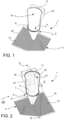
- the object of the present invention is a men's urinal.
- toilets which comprise devices adapted to sanitize certain parts of the toilet intended to come into contact with a user.
- the sanitization of the toilet becomes crucial for protecting the public health and avoiding the spreading of bacteria, particularly when the toilet is not intended for private household use but is conceived to serve a multitude of various individuals, such as by way of non-limiting example, workers and/or commuters and/or travelers, and is installed in a public washroom.
- French Patent Application FR-3015991 shows a solution of a toilet comprising a cup-shaped body, in which there is provided the generation of a water blade which forms a kind of water shield which prevents liquids inside the toilet bowl from accidentally coming out.
- this type of solution imposes making a hinged cover of the bowl adapted to close the bowl itself in an airtight manner, necessarily requiring exceptional manufacturing tolerances.
- the self-cleaning of the toilet in a similar solution requires some time, thus being inadequate for frequent repeated use.
- the need is also felt to provide a solution of a self-cleaning toilet capable of ensuring a sufficient hygiene for certain parts of the toilet intended to also inadvertently come into contact with a user.
- a self-cleaning urinal comprises at least one lower cup-shaped body, having substantially cup- or bowl-shaped body, which delimits at least one emptying opening adapted to be connected with a draining pipe of the self-cleaning urinal, and at least one filling opening, opposite to said emptying opening and adapted to face a user of the self-cleaning urinal.
- Said lower cup-shaped body comprises a side wall which delimits, with an upper edge thereof, at least one portion of said filling opening.
- Said at least one side wall comprises an inner surface and an outer surface which is opposite to said inner surface with respect to said side wall.
- Said at least one side wall at least partially delimits a gap interposed between said inner surface and outer surface, said gap forming at least a first basin adapted to contain a volume of fluid.
- Said first basin leads to both said inner surface and said outer surface by means of at least one discharge mouth.
- Said first basin is connected to an opening of a fluid supply duct adapted to convey a volume of cleaning fluid into said first basin so that when the cleaning fluid received in said first basin overflows, it cleans both said inner surface and said outer surface of the lower cup-shaped body.
- the self-cleaning urinal further comprises at least a second basin preferably comprising at least one filling opening of second basin facing said outer surface of the side wall of the lower cup-shaped body, said outer surface leading to said at least one filling opening of second basin so that said second basin can be supplied with the cleaning fluid which overflowed from said first basin and which already wet said outer surface.
- a self-cleaning urinal with improved hygiene adapted to be used for example in installation in public washrooms, is provided due to the solutions proposed.
- a self-cleaning urinal is provided.
- said in the following named self-cleaning toilet 1 is a men's urinal.
- Said self-cleaning toilet 1 comprises at least one lower cup-shaped body 2.
- Said lower cup-shaped body 2 preferably is substantially cup- or bowl-shaped.
- Said lower cup-shaped body 2 preferably forms the bowl of the self-cleaning toilet 1.
- said lower cup-shaped body 2 delimits at least one emptying opening 3 adapted to be connected with a draining pipe 32 of the self-cleaning toilet 1, and at least one filling opening 4, opposite to said emptying opening 3 and adapted to face a user of the self-cleaning toilet 1.
- Said at least one filling opening 4 preferably substantially is circular.
- said lower cup-shaped body 2 comprises a plurality of emptying openings 3.
- the at least one emptying opening 3 of the lower cup-shaped body 2 may be made on the bottom of the lower cup-shaped body 2.
- Said lower cup-shaped body 2 comprises at least one side wall 5 which delimits, with an upper edge thereof 7, at least one portion of said filling opening 4.
- Said at least one side wall 5 of the cup-shaped body 2 comprises an inner surface 6 which extends between said upper edge 7 and said at least one emptying opening 3 of the lower cup-shaped body 2.
- said inner surface 6 leads to said emptying opening 3 of the lower cup-shaped body 2.
- said inner surface 6 delimits said at least one emptying opening 3 of the lower cup-shaped body 2.
- Said at least one side wall 5 further comprises an outer surface 8 which is opposite to said inner surface 6 with respect to said side wall 5.
- the upper edge 7 of the side wall 5 is formed by a portion of said inner wall 6 and by a facing portion of said outer wall 8.
- Said at least one side wall 5 at least partially delimits a gap 9 interposed between said inner surface 6 and outer surface 8, the gap forming, with said at least one side wall 5, at least a first basin 10, or first tank 10, adapted to contain a volume of cleaning fluid F, F'.
- said side surface 5 of the lower cup-shaped body 2 contains said first basin 10 in the volume thereof.
- the term "basin” preferably means a container adapted to contain fluid, which not necessarily although preferably is open, so as to allow the fluid to overflow from the basin.
- the term “basin” preferably means a vessel adapted to contain a fluid and adapted to allow the fluid to overflow from the basin, and comprising at least one side wall and at least one bottom, in which the bottom may also be formed by said same side wall.
- Said first basin 10 leads to both said inner surface 6 and said outer surface 8.
- said side wall 5 forms a gap 9 therein which is delimited by, and leads to, both said inner surface 6 and said outer surface 8 of the lower cup-shaped body 2.
- Said upper edge 7 of the side wall 5 of the lower cup-shaped body 2 delimits a cleaning opening 33, or discharge mouth 33, due to the provision of such a gap 9 forming said first basin 10.
- said first basin 10 is connected to an opening of a fluid supply duct 30 adapted to convey a volume of cleaning fluid F, F' into said first basin 10 so that when the volume of cleaning fluid F, F' in said first basin 10 overflows, it cleans both said inner surface 6 and said outer surface 8 of the lower cup-shaped body 2.
- said first basin 10 is connectable to said fluid supply duct 30.
- the supply duct 30 is connected to a water supply network or the like so as to supply said first basin 10 with cleaning fluid F, F'.
- cleaning fluid F which preferably is an aqueous solution containing ozone
- a device for pumping the cleaning fluid F, F' preferably is provided.
- the ozone dispersed in the cleaning fluid F, F' is sucked by said pumping device, thus mixing with the water of the cleaning fluid F, F'.
- An ozone detector for detecting possible leaks may be provided on the exterior of toilet 1.
- said first basin 10 is connected to a fluid supply duct 30 adapted to be connected to a water distribution network.
- a fluid supply duct 30 adapted to be connected to a water distribution network.
- the flow of cleaning fluid F, F' which crosses said fluid supply duct 30 fills said first basin 10 and overflowing therefrom, forms both a flow of cleaning fluid F for cleaning the inner surface and a flow of cleaning fluid F' for cleaning the outer surface.
- the flow of cleaning fluid F, F' which crosses said fluid supply duct 30 preferably is a single flow in which the flows of cleaning fluid F, F' for cleaning the inner surface and for cleaning the outer surface, respectively, are indistinguishable.
- the cleaning fluid F, F' crosses the supply duct 30, reaches the first basin 10 formed by said gap 9, thus filling it with fluid and accordingly raising the level of the cleaning fluid F, F' therein.
- the level of cleaning fluid F, F' in basin 10 reaches the upper edge 7, it overflows, passing through at least one discharge mouth 33, cleaning both the inner surface 6 and the outer surface 8 of the lower cup-shaped body 2.
- said at least one discharge mouth 33 leads to both said outer surface 8 and said inner surface 6 of the lower cup-shaped body 2.
- both the interior and the exterior of the cup-shaped portion 2 may be cleaned due to the effect of gravity.
- the outer surface 8 and the inner surface 6 of the side wall 5 each have an upper surface edge 7', 7", and the upper surface edges 7' and 7" of both said inner 6 and outer 8 surface act in conjunction, thus forming the upper edge 7 of the side wall 5, thus delimiting said at least one discharge mouth 33.
- the upper inner surface edge 7' is not necessarily at the same height as the upper outer surface edge 7", although according to a preferred embodiment, they substantially are at the same height.
- the difference in level between said upper inner surface edge 7' and said upper outer surface edge 7" may be selected so as to control the flow rate of the respective flows of cleaning fluid F overflowing from said first basin 10.
- the upper outer surface edge 7" is arranged lower than the upper inner surface edge 7'.
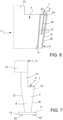
- At least one of said upper inner surface edge 7' and said upper outer surface edge 7" comprises at least one bevel 39 with slope facing towards said inner surface 6 and said outer surface 8, respectively.
- said first basin 10 has the shape of a half-moon defined by said gap 9 of said lower cup-shaped body 2 of the self-cleaning toilet 1.
- said first basin 10 has the shape of at least one ring portion at least partially surrounding the inner surface 6 of the lower cup-shaped body 2.
- the side wall 5 of said cup-shaped body 2 comprises two cup-shaped shells 35, 36 fitted onto each other so that a first cup-shaped shell 36 forms the inner surface 6 and a second cup-shaped shell 35 forms the outer surface 8, and so that said at least one gap 9 which forms said at least a first basin 10 is interposed between said first cup-shaped shell 36 and said second cup-shaped shell 35, said gap being adapted to contain a volume of cleaning fluid F, F'.
- said gap 9 forms said at least one discharge mouth 33 for the cleaning fluid F, F' of the first basin 10, close to the upper edge 7.
- said self-cleaning toilet 1 comprises a single discharge mouth 33 exiting from the first basin 10 for cleaning the inner 6 and outer 8 surfaces of the lower cup-shaped body 2 of the self-cleaning toilet 1.
- the finishing of the upper edge 7 of the side wall 5 may be sized so as to guide the cleaning flow F, F' exiting from the at least one discharge mouth 33 towards the inner wall 6 and/or towards the outer wall 8.
- the at least one discharge mouth 33 of said first basin 10 is wedge-shaped. According to one embodiment, the at least one discharge mouth 33 of said first basin 10 is half-moon shaped. According to one embodiment, the at least one discharge mouth 33 of said first basin 10 has the shape of at least one ring portion delimited by a front portion, i.e. which can frontally face a user of the self-cleaning toilet 1, of the upper edge 7 of said side wall 5.
- the at least one discharge mouth 33 of said first basin 10 substantially is annular-shaped like an annular slit.
- said cup-shaped body 2 comprises a bottom wall 37, e.g. a transverse wall 37, which preferably extends transversely to the inner surface 6 of the cup-shaped body 2 and forms the bottom of said first basin 10.
- said bottom wall 37 is connected, e.g. welded, to both said inner surface 6 and said outer surface 8.
- said transverse wall 37 delimits an emptying hole in fluid communication with said emptying opening 3 of the cup-shaped body 2.
- said cup-shaped body 2 is formed by at least one shaped sheet, which is rolled and welded into edge portions thereof to form a cup-shaped body, e.g. frustoconical shaped.
- the outer wall 5 of said cup-shaped body 2 is formed by at least two shaped sheets, which are rolled and welded in respective edge portions thereof to form at least two cup-shaped shells, e.g. frustoconical shaped, thus interposing a gap between said two cup-shaped shells so as to form said at least a first basin 10.
- said cup-shaped body 2 has a downwards tapered shape.
- said cup-shaped body 2 has a downwards frustoconical shape.
- Said side wall 5 preferably is substantially frustoconical shaped. Said side wall 5 preferably has a downwards tapered shape. According to one embodiment, said filling opening 4 has a larger perimeter than said emptying opening 3 and both are delimited by said inner surface 6 of the side wall 5 of the lower cup-shaped body 2.
- said side wall 5 of the lower cup-shaped body 2 substantially is frustoconical shaped, in which said inner surface 6 and said outer surface 8 of the side wall 5 are not parallel to each other. Thereby, an angle is defined between said inner surface 6 and said outer surface 8.
- the provision of said non-parallel inner surface 6 and said outer surface 8 of the frustoconical side wall 5 causes the cleaning fluid F and F' to wet two inclined surfaces formed by the inner 6 and outer 8 surfaces, respectively, having different slope. Thereby, a difference in speed may be caused of the cleaning fluid F, F' which wets the inner surface 6 and the one which wets the outer surface 8.
- the inclination of the outer surface 8 of the lower cup-shaped body 2 is selected so that the cleaning fluid F' which wets it by overflowing from said discharge mouth 33 remains adhering to the outer surface 8, thus avoiding the formation of drops.
- a control and operating device comprising at least one presence sensor 23, a data processing unit 24 and at least one operating device 25, in which said presence sensor 23 is adapted to detect information on the presence or absence of a user of the self-cleaning toilet 1 and to transfer said detected information to said data processing unit 24, and in which said data processing unit 24 acts in conjunction with said operating device 25 to allow the cleaning fluid F, F' to flow from the supply duct 30 to the first basin 10, thus filling it.
- said supply duct 30 comprises a valve 28, for example a valve which is normally closed, for example a solenoid valve, controlled by the operating device 25.
- Said presence sensor 23 preferably comprises a photocell.
- the cleaning of the self-cleaning toilet 1 may be automated due to the provision of such a control device 24.
- said control device comprises at least one further sensor adapted to detect the level of cleaning fluid F, F' in said first basin 10.
- said cup-shaped portion 2 is cylindrical shaped.
- said side wall 5 comprises a partition septum 29 interposed between the outer surface 8 and the inner surface 6 of the side wall 5 of the lower cup-shaped body 2, said septum 29 acting as divide for the cleaning fluid F, F' overflowing from said first basin 10.
- said septum 29 defines two outlet mouths 33, 34, or discharge mouths 33, 34, of the cleaning fluid F, F' from the first basin 10.
- a first outlet mouth 33 partially delimited by said septum 29 is adapted to bring the cleaning fluid F overflowing from the first basin 10 onto said inner surface 6.
- a second outlet mouth 34 partially delimited by said septum 29 is adapted to bring the cleaning fluid F' overflowing from the first basin 10 onto said outer surface 8.
- said septum 29 is an arched foil.
- Said septum 29 preferably is obtained from a shaped sheet welded in the edge portions thereof to said cup-shaped body 2, preferably at the walls of the cup-shaped body 2 which delimit said gap 9 which forms the first basin 10.
- said septum 29 delimits said two outlet mouths 33, 34 in which the first outlet mouth 33 is radially inwards with respect to the second outlet mouth 34, in which the term "radially inwards" means the position with respect to a definable radial radius of the cup-shaped portion 2, preferably a frustoconical cup-shaped portion 2.
- Said septum 29 which acts as divide preferably is arranged on the upper edge 7 of the cup-shaped body 2.
- said septum 29 divides said at least one gap 9 into at least two gaps, said at least two gaps may be mutually communicating, thus forming a single first basin 10, or they may be isolated from each other to each form a first basin 10.
- said side wall 5 comprises at least two first basins 10.
- said side wall 5 delimits at least two substantially concentric gaps 9.
- Two outlet mouths 33, 34 may be made due to the provision of said septum 29, one which leads to the outer surface 8 of the cup-shaped body 2 and the other to the inner surface 6 of the cup-shaped body 2.
- said self-cleaning toilet 1 comprises at least a second basin 12, or second tank 12, which is supplied by the cleaning fluid F' which overflowed from said first basin 10 and which already cleaned said outer surface 8 of the side wall 5 of the lower cup-shaped body 2.
- said second basin 12 is adapted to collect the cleaning fluid F' which already cleaned said outer surface 8 of the side wall 5 of the self-cleaning toilet 1.
- said second basin 12 is arranged at the bottom with respect to said outer surface 8 of the side wall 5.
- said outer surface 8 of the side wall 5 extends between said upper edge 7 and said second basin 12.
- said second basin 12 comprises at least a second basin opening 40 facing said outer surface 8 of the side wall 5 of the lower cup-shaped body 2.
- said at least a second basin opening 40 is at least partially delimited by said outer surface 8 of the side wall 5 of the lower cup-shaped body 2.
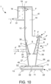
- said self-cleaning toilet 1 further comprises a box-like support 11 which supports said lower cup-shaped body 2 in position.
- Said box-like support 11 preferably has box-like shape which comprises said second basin 12, or second tank 12.
- a connection flange may be provided on the lower portion of the lower cup-shaped body 2 for the connection thereof to the box-like support 11.
- said lower cup-shaped body 2 is fastened, e.g. welded, to said support 11.
- said box-like support 11 further comprises a cover grate 13 forming a floor surface which is over the second basin 12.
- a user of the self-cleaning toilet 1 may rest or tread on said cover grate 13 in order to surmount said second basin 12, thus avoiding to be required to place his feet in the second basin 12 during the use of the self-cleaning toilet 1, e.g. a urinal.
- the section of the elements forming such a grate 13 may be tapered to minimize the contact surface with the soles of a user of toilet 1.
- said support 11 is arranged under the cup-shaped body 2 so that the outer surface 8 of the side wall 5 of the lower cup-shaped body 2 leads into said second basin 12.
- Said second basin 12 preferably is supplied by the cleaning fluid F' overflowing from said first basin 10 and which cleans said outer surface 8 of the side wall 5 of the cup-shaped body 2.
- Said second basin opening 40 preferably is arranged under said outer surface 8 of the side wall 5 of the lower cup-shaped body 2 so that said second basin opening 40 is facing said outer surface 8 in vertical direction, i.e. direction of the force of gravity.
- the cleaning fluid F' which wets the outer surface 8 may flow into the second basin 12 both by flowing over the outer surface 8 itself and by trickling or dripping vertically from the outer surface 8 into the second basin 12.
- the cleaning fluid F' for cleaning the outer surface may be collected inside said second basin 12 after the cleaning of said outer surface 8 of the lower cup-shaped body 2.
- the inclination of the outer surface 8 and also the surface finish of the outer surface 8 and also the flow rate of the cleaning fluid F' which cleans the outer surface 8 may be selected so as to allow the cleaning fluid F' which cleans the outer surface 8 to flow into the second basin opening 40.
- said second basin 12 is adapted to be connected with a draining pipe 32 of the self-cleaning toilet 1.
- said second basin 12 is directly or indirectly connected to the drain 32, for example by interposing a stretch of outlet duct 32' of second basin associated with an overflow indicator.
- said cover grate 13 is arranged at a lower level with respect to edge 18 of the second basin 12.
- the upper edge 18 of said second basin forms a side which exceeds the level of the cover grate 13.
- the height of said edge 18, or side may be selected so that the difference in level between edge 18 and the cover grate 13 forming the floor surface is minimum so as to avoid submerging the shoes of a user of the toilet, while cleaning the sole thereof.
- the cleaning fluid F collected in the second basin 12 may overflow towards drain 32, submerging, cleaning the cover grate 13, in this manner also sanitizing a portion of the sole of a shoe of a user of the self-cleaning toilet 1.
- the sizing of the crosswise or lengthwise elements of the grating of the cover grate 13 may be selected to absolve the function of supporting a user on said second basin 12 and simultaneously allow the cleaning fluid F' to flow into the second basin 12 after cleaning the outer surface 8.
- the cleaning fluid F' which overflows from said first basin 10 cleans the outer surface 8 of the lower cup-shaped body 2 and accumulates in the second basin 12.
- the second basin draining pipe of the second basin 12 and said emptying opening 3 of the self-cleaning toilet 1 both flow into the same drain 32, for example a same channeling of a sewer or urban draining system.
- said second basin 12 overflows towards drain 32.
- the level of cleaning fluid F' in the second basin 12 exceeds the one of edge or side 18, preferably it overflows from the second basin 12 and goes into drain 32.
- said box-like support 11 comprises a tilt adjustment device 22 adapted to keep said second basin 12 substantially horizontal or level.
- said tilt adjustment device 22 is adapted to also keep level said cup-shaped body 2 which is associated with said box-like support 11.
- said tilt adjustment device 22 is telescopically extendable and comprises a first body and a second body, in which said first body and said second body are fitted onto each other so as to be telescopically extendable.
- said tilt adjustment device 22 comprises at least one screw jack.
- said tilt adjustment device 22 comprises at least one pair of adjustable legs, preferably at least three independently adjustable legs.
- said second basin 12 is provided with an overflow device, for example an overflow hole, arranged at a predetermined vertical distance from the cover grate 13 so as to allow the at least partial emptying of the second basin 12 when the cleaning fluid F' reaches a predefined level, thus occupying a predefined volume, in said second basin 12.
- said control device 24 is operatively connected to a sensor adapted to detect the level of cleaning fluid F' in said second basin 12 in order to verify the proper operation of the overflow element, so that the control device 24 transmits control signals to said at least one valve 28 so it closes.
- the self-cleaning toilet 1 may operate without the automatic cleaning of the outer surface 8 of the cup-shaped body 2.
- said second basin 12 is adapted to be installed locally embedded in the floor, bringing said edge 18 or said grate 13 substantially locally flush with the floor level 38 so as to eliminate the presence, or at least minimize the entity, of a step for a user approaching the self-cleaning toilet 1.
- One or more fastening brackets may be provided for fastening the second basin 12 to the floor or to a floor slab.
- said self-cleaning toilet 1 further comprises an upper shield 14 comprising a containing wall 15 adapted to face a user of the self-cleaning toilet 1.
- said containing wall 15 is substantially vertical oriented.
- said self-cleaning toilet 1 further comprises a third basin 16, or third tank 16, adapted to receive cleaning fluid F for cleaning the inner surface.
- Said third basin 16 preferably is associated with said upper shield 15.
- said third basin 16 is supplied by a supply duct 31 which can be associated with the self-cleaning toilet 1. The flow of cleaning fluid F which crosses said supply duct 31 is collected in said third basin 16 and is intended for cleaning the inner surface 6 of the lower cup-shaped body 2.
- said supply duct 31 is associated with a valve 28 controlled by the control device.
- said third basin 16 is arranged at the top with respect to said upper shield 15.
- said third basin 16 is over said upper shield 15.
- said third basin 16 delimits, with the walls thereof, a third basin opening 17 which leads to said containing wall 15.
- said at least a third basin opening 17 is at least partially delimited by said containing wall 15, and preferably by the upper edge 19 of the containing wall 15.
- said at least a third basin opening 17 is in the shape of a slit, preferably a curved slit, for example annular or semi-annular, adapted to frontally face a user of the self-cleaning toilet 1.
- said at least a third basin opening 17 leads frontally flush with the containing wall 15 of the upper shield 14 so as to clean it due to the effect of gravity.
- said third basin 16 is arranged behind the upper shield 14. Thereby, the third basin 16 may be frontally concealed from the sight of a user, when needed. According to one embodiment, said third basin 16 is frontally delimited by said upper shield 14. According to one embodiment, said third basin 16 has greater width than the upper shield 14. Thereby, a third basin opening 17 may be obtained, for example a slit, which extends for the whole extension of the containment surface 15, to clean it. Said third basin 16 for example, is in the shape of a box-like container in the shape of a parallelepiped which comprises two side extensions which extend outside of the upper shield 14.
- said containing wall 15 is in the shape of a portion of cylindrical surface. For example, it is substantially vertically oriented. According to one embodiment, said containing wall 15 comprises an arched surface which forms a curved face facing a user of the toilet.
- said containing wall 15 is adapted to convey the cleaning fluid F towards said lower cup-shaped body 2 of the self-cleaning toilet 1 to clean at least the inner surface 6 of the rear portion 27 of the side wall 5 of the lower cup-shaped body 2.
- said containing wall 15 comprises at least one containing edge 41 and preferably is delimited by a pair of containing edges 41 arranged at the ends thereof and facing it to form a barrier against the accidental cleaning of a user with the cleaning fluid F outlet from said third opening 17 for cleaning the upper shield 14.
- said lower cup-shaped body 2 of the self-cleaning toilet 1 comprises a front portion 26, which can face a user of the self-cleaning toilet 1 when under operating conditions, and an opposed rear portion 27, opposite to said front portion 26 with respect to said filling opening of the lower cup-shaped body 2.
- said front portion 26 of the lower cup-shaped body 2 completely delimits said gap 9, forming said first basin 10 which leads from the upper edge 7 of the front portion 26 of the cup-shaped portion 2.
- the upper edge 7 of the side wall 5 of the lower cup-shaped body 2 delimits said at least one discharge mouth 33 only on the front side of the cup-shaped body 2, thus avoiding to provide said at least one discharge mouth 33 in the rear portion 27.
- the term "front side” preferably means the side of the cup-shaped body which is approached by a user of the toilet under operating conditions.
- the at least one discharge mouth 33 extends along the whole upper perimeter of the upper edge 7 of the side wall 5 of the front portion 26 of the lower cup-shaped body 2.
- said rear portion 27 of the lower cup-shaped body 2 forms said upper shield 14 without a gap.
- the inner wall 6 of the rear portion 27 of the lower cup-shaped body 2 forms a single piece with, or is welded to, the containing wall 15 of the upper shield 14.
- the cleaning of the rear portion 27 is obtained mainly due to the cleaning fluid F which overflows from the third basin 16 which, leading to the rear shield 14 by means of said third basin opening 17, cleans both the containment surface 15 of the upper shield 14 and the inner surface 6 of the rear portion 27 of the lower cup-shaped body 2 due to the effect of gravity.
- the cleaning of both the inner 6 and outer 8 surfaces of the side wall 5 of the front portion 26 of the lower cup-shaped body 2 occurs due to the cleaning fluid F which overflows from said first basin 10.
- said upper shield 14 is formed by a shaped sheet, which is rolled and preferably welded in edge portions thereof to said cup-shaped body 2.
- said inner surface 6 is a single piece.
- said inner surface 6 of the rear portion 27 and the inner surface 6 of the front portion 26 of the side wall 5 of the cup-shaped portion 2 are two portions of the same surface.
- said inner surface 6 is a surface having cylindrical symmetry which extends about a substantially vertical symmetry axis.
- said inner surface 6 is a frustoconical surface.
- said rear portion 27 of the lower cup-shaped body 2 does not have cleaning openings.
- said rear portion 27 forms a first cup-shaped half body of the lower cup-shaped body 2 and said front portion 26 forms a second cup-shaped half body of the lower cup-shaped body 2 so that said rear portion 27 and said front portion 26 jointly form the body of the cup-shaped portion of the toilet.
- a cleaning opening 33 preferably is arranged only on the front portion 26. The cleaning of the rear portion 27 preferably occurs due to the third basin opening 17 from which the cleaning fluid F overflows which cleans the upper shield 15 by gravity and then the inner surface 6 of the rear portion 27. According to one embodiment, cleaning the outer surface 8 of the side wall 5 of the rear portion 27 is avoided.
- the shape of the inner surface 6 of the lower cup-shaped body 2 is selected so that it forms vorticities in the cleaning fluid F for cleaning the inner surface which overflows from said first basin 10 and/or from said third basin 16. Thereby, the self-cleaning efficiency of the self-cleaning toilet 1 is increased.
- the inner surface 6 of the lower cup-shaped body 2 substantially is smooth to avoid stagnating areas.
- said operating device 25 is adapted to selectively open both the supply duct 30 of the first basin 10 and the supply duct 31 of the third basin 16. Thereby, both the lower cup-shaped body 2 and the upper shield 15 are cleaned with a single command.
- said operating device 25 is controlled by a manually-operated control lever.
- said self-cleaning toilet 1 comprises a tank of detergent containing ozone, in which said tank of detergent is in fluid connection both with said first basin 10 and with said second basin 16.
- said self-cleaning toilet 1 is completely made of metal.
- said self-cleaning toilet is made of steel.
- said self-cleaning toilet 1 is made of metal, for example crude metal or satin metal.
- said lower cup-shaped body 2 and/or said upper shield 14 of said self-cleaning toilet 1 is made of steel, preferably stainless steel, crude and/or satin stainless steel. The provision of said self-cleaning toilet 1 made of metal, e.g. steel, allows the material to be recycled, for example in a foundry.
- said lower cup-shaped body 2 and/or said upper shield 14 are at least partially made of ceramic for toilets or the like.
- said lower cup-shaped body 2 and/or said upper shield 14 are made of metal covered with ceramic for toilets.
- said self-cleaning toilet 1 is resting on said box-like support 11.
- said self-cleaning toilet comprises wall fastening means, for example threaded means, adapted to form a support connection between the self-cleaning toilet and a wall of a building 21.
- said self-cleaning toilet 1 forms a modular unit for public washrooms.
- an assembly 20 of modular units for public washrooms comprises a plurality of self-cleaning toilets 1 according to any one of the embodiments described above.
- said assembly 20 comprises a single box-like support 11 with which a plurality of self-cleaning toilets 1 is associated.
- Said single box-like support 11 preferably forms a single second basin 12.
- Said single box-like support 11 may be mounted recessed in a floor.
- a method for cleaning a toilet 1 is described below.
- a method for cleaning a toilet 1 comprises the step of causing the cleaning of both said inner surface 6 and said outer surface 8 of said lower cup-shaped body 2 by means of a single control. Thereby, it is avoided for an operator to have to clean the surfaces 6 and 8 of the cup-shaped body 2.
- said step of causing the cleaning of both said inner surface 6 and said outer surface 8 of the side wall 5 of the lower cup-shaped body 2 is executed by providing a gap 9 in the side wall 5 which forms a first basin 10, or first tank 10, which leads to both said inner surface 6 and said outer surface 8 of the side wall 5.
- Said step of causing the cleaning of both said inner surface 6 and said outer surface 8 preferably is executed by providing a single discharge mouth 33 on the upper edge 7 of the side wall 5 of the lower cup-shaped body 2 which leads to both said inner surface 6 and said outer surface 8 of the lower cup-shaped body 2.
- the method comprises the step of flooding said first basin 10 with cleaning fluid F, F' so that it overflows.
- the method comprises the step of adjusting the related height of the upper surface edges 7' and 7" of the inner 6 and outer 8 surfaces of the side wall 5 of the lower cup-shaped body 2.
- the flow rate of cleaning fluid F overflowing from said first basin 10 which cleans the inner surface 6 and the flow rate of cleaning fluid F' overflowing from said first basin 10 which cleans the outer surface 8 may be adjusted.
- the method comprises the step of adjusting the inclination of the outer surface 8 with respect to the vertical direction so that the cleaning fluid F' overflowing from said first basin 10 adheres, wetting it at the outer surface 8.
- the method comprises the step of providing a self-cleaning toilet 1 according to any one of the embodiments described above.
- the method comprises the further step of causing the cleaning also of said cover grate 13 of the second basin 12 arranged at the bottom with respect to the lower cup-shaped body 2.
- the method comprises the further step of causing the cleaning also of said containment surface 15 of the upper shield 14 by means of said single control.
- said single control is provided by a user of the toilet by means of the operation of a control lever or an operating button.
- said single control is provided by a control and operating device in response to information detected by at least one sensor 23.
Landscapes
- Health & Medical Sciences (AREA)
- Public Health (AREA)
- Life Sciences & Earth Sciences (AREA)
- Engineering & Computer Science (AREA)
- Hydrology & Water Resources (AREA)
- Water Supply & Treatment (AREA)
- Epidemiology (AREA)
- Sanitary Device For Flush Toilet (AREA)
- Bidet-Like Cleaning Device And Other Flush Toilet Accessories (AREA)
- Detergent Compositions (AREA)
Claims (15)
- Selbstreinigendes Urinal (1), umfassend:- wenigstens einen unteren schalenförmigen Körper (2), welcher im Wesentlichen eine Schalenform aufweist, wobei der untere schalenförmige Körper (2) wenigstens eine Entleerungsöffnung (3), welche dazu eingerichtet ist, mit einem Entwässerungsrohr des selbstreinigenden Urinals (1) verbunden zu sein, und wenigstens eine Füllöffnung (4) begrenzt, welche der Entleerungsöffnung (3) entgegengesetzt ist und dazu eingerichtet ist, einem Benutzer des selbstreinigenden Urinals (1) zugewandt zu sein; wobei- der untere schalenförmige Körper (2) wenigstens eine Seitenwand (5) umfasst, welche, mit einem oberen Rand (7) davon, wenigstens einen Abschnitt der Füllöffnung (4) begrenzt;- die wenigstens eine Seitenwand (5) eine innere Fläche (6) und eine äußere Fläche (8) umfasst, welche in Bezug auf die Seitenwand (5) der inneren Fläche (6) entgegengesetzt ist;- die wenigstens eine Seitenwand (5) wenigstens teilweise einen Spalt (9) begrenzt, welcher zwischen der inneren Fläche (6) und der äußeren Fläche (8) eingefügt ist, wobei der Spalt wenigstens ein erstes Bassin (10) bildet, welches dazu eingerichtet ist, ein Volumen von Fluid zu enthalten;- wobei das erste Bassin (10) mittels wenigstens einer Ablaufmündung (33) zu sowohl der inneren Fläche (6) als auch der äußeren Fläche (8) führt;- wobei das erste Bassin (10) mit einer Öffnung eines Fluidzufuhrkanals (30) verbunden ist, welcher dazu eingerichtet ist, ein Volumen eines Reinigungsfluids (F, F') in das erste Bassin (10) zu fördern, so dass, wenn das in dem ersten Bassin (10) aufgenommene Reinigungsfluid (F, F') überläuft, es sowohl die innere Fläche (6) als auch die äußere Fläche (8) des unteren schalenförmigen Körpers (2) reinigt; und wobei:- das selbstreinigende Urinal (1) ferner wenigstens ein zweites Bassin (12) umfasst, welches wenigstens eine Öffnung eines zweiten Bassins umfasst, welche der äußeren Fläche (8) der Seitenwand (5) des unteren schalenförmigen Körpers (2) zugewandt ist;- wobei die äußere Fläche (8) zu der wenigstens einen Öffnung eines zweiten Bassins führt, so dass das zweite Bassin (12) mit dem Reinigungsfluid (F') zum Reinigen der äußeren Wand (8) versorgt werden kann, welches von dem ersten Bassin (10) übergelaufen ist.
- Selbstreinigendes Urinal (1) nach Anspruch 1, wobei der untere schalenförmige Körper (2) eine verjüngte Form, vorzugsweise eine im Wesentlichen kegelstumpfförmige Form, aufweist.
- Selbstreinigendes Urinal (1) nach Anspruch 1 oder 2, wobei die innere Fläche (6) und die äußere Fläche (8) der Seitenwand (5) nicht-parallel zueinander sind.
- Selbstreinigendes Urinal (1) nach einem der vorhergehenden Ansprüche, wobei die wenigstens eine Ablaufmündung (33) des ersten Bassins (10) halbmondförmig ist.
- Selbstreinigendes Urinal (1) nach einem der vorhergehenden Ansprüche, wobei der untere schalenförmige Körper (2) einen vorderen Abschnitt (26), welcher, unter Betriebsbedingungen, einem Benutzer des selbstreinigenden Urinals (1) zugewandt sein kann, und einen entgegengesetzten hinteren Abschnitt (27) umfasst, welcher dem vorderen Abschnitt (26) in Bezug auf die Füllöffnung (4) des unteren schalenförmigen Körpers (2) entgegengesetzt ist; wobei der vordere Abschnitt (26) den Spalt (9) vollständig begrenzt, wodurch das erste Bassin (10) gebildet ist, welches von dem oberen Rand (7) des vorderen Abschnitts (26) führt; und wobei sich die Ablaufmündung (33) im Wesentlichen entlang des gesamten oberen Umfangs des oberen Rands (7) des vorderen Abschnitts (26) des unteren schalenförmigen Körpers (2) erstreckt.
- Selbstreinigendes Urinal (1) nach einem der vorhergehenden Ansprüche, ferner umfassend eine kastenartige Halterung (11), welche den unteren schalenförmigen Körper (2) in Position haltert, wobei die kastenartige Halterung (11) einen kastenartigen Körper, welcher das wenigstens eine zweite Bassin (12) bildet, und ein Abdeckungsgitter (13) aufweist, welches eine Bodenfläche bildet, welche sich über dem zweiten Bassin (12) befindet; und/oder wobei- die Öffnung eines zweiten Bassins unter der äußeren Fläche (8) der Seitenwand (5) des unteren schalenförmigen Körpers (2) angeordnet ist.
- Selbstreinigendes Urinal (1) nach Anspruch 6, wobei die kastenartige Halterung (11) eine Neigungseinstellungsvorrichtung (22) umfasst, welche dazu eingerichtet ist, das Niveau des unteren schalenförmigen Körpers (2) zu halten.
- Selbstreinigendes Urinal (1) nach einem der vorhergehenden Ansprüche, wobei die wenigstens eine Öffnung (12) eines zweiten Bassins wenigstens teilweise durch die äußere Fläche (8) der Seitenwand (5) des unteren schalenförmigen Körpers (2) begrenzt ist.
- Selbstreinigendes Urinal (1) nach einem der vorhergehenden Ansprüche, ferner umfassend einen oberen Schild (14), welcher eine Behälterwand (15) umfasst, welche dazu eingerichtet ist, einem Benutzer des selbstreinigenden Urinals (1) zugewandt zu sein, wobei der obere Schild (14) ein drittes Bassin (16) umfasst, welches mittels wenigstens einer Öffnung (17) eines dritten Bassins zu der Behälterwand (15) führt, so dass die Behälterwand (15) dazu eingerichtet ist, dass Reinigungsfluid (F), welches von dem dritten Bassin (16) überläuft, zu dem unteren schalenförmigen Körper (2) der selbstreinigenden Toilette (1) zu führen, um wenigstens die innere Fläche (6) des hinteren Abschnitts (27) der Seitenwand (5) des unteren schalenförmigen Körpers (2) zu reinigen.
- Selbstreinigendes Urinal (1) nach einem der vorhergehenden Ansprüche, wobei das selbstreinigende Urinal (1) aus Metall, vorzugsweise aus rohem oder satiniertem nichtrostenden Stahl hergestellt ist.
- Selbstreinigendes Urinal (1) nach einem der vorhergehenden Ansprüche, umfassend eine Steuerungs-und-Betätigungsvorrichtung, umfassend wenigstens einen Anwesenheitssensor (23), eine Datenverarbeitungseinheit (24) und wenigstens eine Betätigungsvorrichtung (25), wobei der wenigstens eine Anwesenheitssensor (23) dazu eingerichtet ist, Informationen hinsichtlich der Anwesenheit oder der Abwesenheit eines Benutzers des selbstreinigenden Urinals (1) zu detektieren und die detektierten Informationen zu der Datenverarbeitungseinheit (24) zu übertragen, und wobei die Datenverarbeitungseinheit (24) in Verbindung mit der Betätigungsvorrichtung (25) wirkt, um dem Reinigungsfluid (F, F') zu erlauben, von dem Zufuhrkanal (30) zu dem ersten Bassin (10) zu laufen, um dieses zu füllen.
- Selbstreinigendes Urinal (1) nach einem der vorhergehenden Ansprüche, wobei die Seitenwand (5) des unteren schalenförmigen Körpers (2) zwei schalenförmige Hüllen (35, 36) umfasst, welche aufeinander gepasst sind, so dass eine erste schalenförmige Hülle (36) die innere Fläche (6) bildet und eine zweite schalenförmige Hülle (35) die äußere Fläche (8) bildet und so dass der wenigstens eine Spalt (9), welcher das wenigstens eine erste Bassin (10) bildet, zwischen der ersten schalenförmigen Hülle (36) und der zweiten schalenförmigen Hülle (35) eingefügt ist, wobei der Spalt dazu eingerichtet ist, ein Volumen von Reinigungsfluid (F, F') zu enthalten.
- Selbstreinigendes Urinal (1) nach einem der vorhergehenden Ansprüche, wobei der untere schalenförmige Körper (2) durch wenigstens ein geformtes Blech gebildet ist, welches gewalzt und in den Randabschnitten davon geschweißt ist, um einen unteren schalenförmigen, beispielsweise einen kegelstumpfförmigen, Körper zu bilden; und/oder wobei- die Seitenwand (5) des unteren schalenförmigen Körpers (2) durch wenigstens zwei geformte Bleche gebildet ist, welche gewalzt und in jeweiligen Randabschnitten davon geschweißt sind, um wenigstens zwei schalenförmige, beispielsweise kegelstumpfförmige, Hüllen zu bilden, wodurch ein Spalt zwischen den beiden schalenförmigen Hüllen eingefügt wird, um das wenigstens eine erste Bassin (10) zu bilden.
- Selbstreinigendes Urinal (1) nach einem der vorhergehenden Ansprüche, wobei die Seitenwand (5) eine Trennwand (29) umfasst, welche zwischen der äußeren Fläche (8) und der inneren Fläche (6) der Seitenwand (5) des unteren schalenförmigen Körpers (2) eingefügt ist, wobei die Trennwand (29) als eine Teilung für das Reinigungsfluid (F, F') wirkt, welches von dem ersten Bassin (10) überläuft, so dass die Trennwand (29) zwei Auslassmündungen (33, 34) zum Ablaufen des Reinigungsfluids (F, F') aus dem ersten Bassin (10) definiert.
- Anordnung (20) modularer Einheiten für einen öffentlichen Waschraum, welche eine Mehrzahl selbstreinigender Urinale (1) nach einem der vorhergehenden Ansprüche umfasst.
Applications Claiming Priority (2)
| Application Number | Priority Date | Filing Date | Title |
|---|---|---|---|
| IT102018000007107A IT201800007107A1 (it) | 2018-07-11 | 2018-07-11 | Sanitario autopulente e metodo di pulizia |
| PCT/IB2019/055921 WO2020012405A1 (en) | 2018-07-11 | 2019-07-11 | Self-cleaning toilet, particularly for use as a urinal |
Publications (3)
| Publication Number | Publication Date |
|---|---|
| EP3821086A1 EP3821086A1 (de) | 2021-05-19 |
| EP3821086C0 EP3821086C0 (de) | 2023-06-07 |
| EP3821086B1 true EP3821086B1 (de) | 2023-06-07 |
Family
ID=63684349
Family Applications (1)
| Application Number | Title | Priority Date | Filing Date |
|---|---|---|---|
| EP19746179.1A Active EP3821086B1 (de) | 2018-07-11 | 2019-07-11 | Selbstreinigende toilette, insbesondere für benutzung als urinal |
Country Status (7)
| Country | Link |
|---|---|
| US (1) | US11319701B2 (de) |
| EP (1) | EP3821086B1 (de) |
| CA (1) | CA3106101A1 (de) |
| ES (1) | ES2950820T3 (de) |
| IT (1) | IT201800007107A1 (de) |
| PL (1) | PL3821086T3 (de) |
| WO (1) | WO2020012405A1 (de) |
Families Citing this family (3)
| Publication number | Priority date | Publication date | Assignee | Title |
|---|---|---|---|---|
| WO2019213762A1 (en) * | 2018-05-10 | 2019-11-14 | Foda Mohamed M R | Device for sanitary drainage of an ostomy pouch |
| USD968577S1 (en) * | 2020-02-20 | 2022-11-01 | Eddie Lor | Urinal |
| IT202000012157A1 (it) | 2020-05-25 | 2021-11-25 | In Giardino S R L | Dispositivo per la protezione degli spazi dagli insetti nocivi con variazione automatica del dosaggio della soluzione impiegata |
Family Cites Families (8)
| Publication number | Priority date | Publication date | Assignee | Title |
|---|---|---|---|---|
| DE79060C (de) * | 1894-03-29 | 1895-01-16 | C. A. RUDOLPH, Zittau i. S | Abtritt-Anlage ohne Wasserzuführung |
| US645686A (en) * | 1899-09-16 | 1900-03-20 | William K Johnson | Closet-bowl. |
| US2116529A (en) | 1936-04-20 | 1938-05-10 | John Douglas Company | Flush bowl structure |
| US3585649A (en) * | 1967-11-30 | 1971-06-22 | Nepon Kk | Toilet unit utilizing self-maintained foam |
| US3772711A (en) * | 1972-04-03 | 1973-11-20 | S Spector | Toilet with disposable receptacle |
| JPH08128100A (ja) * | 1993-12-21 | 1996-05-21 | Japanic:Kk | 便器の洗浄機構 |
| JP2007046438A (ja) | 2005-08-11 | 2007-02-22 | Masahiro Ishii | 自動掃除便器 |
| FR3015991A1 (fr) | 2013-12-26 | 2015-07-03 | Fabrice Coudin | Wc hygieniques |
-
2018
- 2018-07-11 IT IT102018000007107A patent/IT201800007107A1/it unknown
-
2019
- 2019-07-11 EP EP19746179.1A patent/EP3821086B1/de active Active
- 2019-07-11 WO PCT/IB2019/055921 patent/WO2020012405A1/en unknown
- 2019-07-11 CA CA3106101A patent/CA3106101A1/en active Pending
- 2019-07-11 PL PL19746179.1T patent/PL3821086T3/pl unknown
- 2019-07-11 US US17/259,422 patent/US11319701B2/en active Active
- 2019-07-11 ES ES19746179T patent/ES2950820T3/es active Active
Also Published As
| Publication number | Publication date |
|---|---|
| EP3821086C0 (de) | 2023-06-07 |
| ES2950820T3 (es) | 2023-10-13 |
| IT201800007107A1 (it) | 2020-01-11 |
| WO2020012405A1 (en) | 2020-01-16 |
| CA3106101A1 (en) | 2020-01-16 |
| PL3821086T3 (pl) | 2023-10-09 |
| US11319701B2 (en) | 2022-05-03 |
| US20210262216A1 (en) | 2021-08-26 |
| EP3821086A1 (de) | 2021-05-19 |
Similar Documents
| Publication | Publication Date | Title |
|---|---|---|
| EP3821086B1 (de) | Selbstreinigende toilette, insbesondere für benutzung als urinal | |
| US5645103A (en) | Water heater stand with overflow catch basin | |
| US5142712A (en) | Vacuum assisted toilet | |
| EP2321478A1 (de) | Sitz- und hockwasserklosett sowie sitz mit darunter befindlicher zisterne | |
| EP1854929B1 (de) | Abfluss | |
| CN111074976A (zh) | 具有供水系统的卫生设备、水路系统及洗手台 | |
| KR101253981B1 (ko) | 소변기용 위생장치 | |
| IE47759B1 (en) | Trapped gulley | |
| US7621002B1 (en) | System and method for controlling, draining, removing, and disposing of liquids and light solids | |
| CN101379251A (zh) | 在成形卫生器具期间可直接得到的虹吸系统 | |
| KR102251074B1 (ko) | 양변기 단부 세척기 또는 이를 포함한 양변기 | |
| EP0821754A1 (de) | Fussbodenschutz und reinigung für herrentoiletten | |
| JP7411926B2 (ja) | 水洗便器及び便器装置 | |
| EP1426505A2 (de) | Universeller Spender für Desinfektionsflüssigkeit für Wasserbehälter o. ä., insbesondere für Spülkästen für Toiletten | |
| KR101918037B1 (ko) | 소변기용 절수위생 배수 트랜치 | |
| JP6329233B2 (ja) | 床構造体 | |
| RU2742827C2 (ru) | Комплект санузла | |
| JPH0626090A (ja) | 水洗式小便器 | |
| KR20210104373A (ko) | 낙하요 세척장치 | |
| US335601A (en) | Urinal | |
| FI112442B (fi) | Menetelmä rasvan erottamiseksi jätevedestä erotinlaitteelle sekä erotinlaite | |
| CN116867946A (zh) | 抽水马桶 | |
| KR20220099357A (ko) | 보조 오물 배출 경로를 갖는 변기 시스템 | |
| JPH07305395A (ja) | 壁掛け式洋風便器 | |
| US892523A (en) | Washstand. |
Legal Events
| Date | Code | Title | Description |
|---|---|---|---|
| STAA | Information on the status of an ep patent application or granted ep patent |
Free format text: STATUS: UNKNOWN |
|
| STAA | Information on the status of an ep patent application or granted ep patent |
Free format text: STATUS: THE INTERNATIONAL PUBLICATION HAS BEEN MADE |
|
| STAA | Information on the status of an ep patent application or granted ep patent |
Free format text: STATUS: THE INTERNATIONAL PUBLICATION HAS BEEN MADE |
|
| PUAI | Public reference made under article 153(3) epc to a published international application that has entered the european phase |
Free format text: ORIGINAL CODE: 0009012 |
|
| STAA | Information on the status of an ep patent application or granted ep patent |
Free format text: STATUS: REQUEST FOR EXAMINATION WAS MADE |
|
| 17P | Request for examination filed |
Effective date: 20210113 |
|
| AK | Designated contracting states |
Kind code of ref document: A1 Designated state(s): AL AT BE BG CH CY CZ DE DK EE ES FI FR GB GR HR HU IE IS IT LI LT LU LV MC MK MT NL NO PL PT RO RS SE SI SK SM TR |
|
| DAV | Request for validation of the european patent (deleted) | ||
| DAX | Request for extension of the european patent (deleted) | ||
| GRAP | Despatch of communication of intention to grant a patent |
Free format text: ORIGINAL CODE: EPIDOSNIGR1 |
|
| STAA | Information on the status of an ep patent application or granted ep patent |
Free format text: STATUS: GRANT OF PATENT IS INTENDED |
|
| INTG | Intention to grant announced |
Effective date: 20221012 |
|
| GRAS | Grant fee paid |
Free format text: ORIGINAL CODE: EPIDOSNIGR3 |
|
| RIN1 | Information on inventor provided before grant (corrected) |
Inventor name: PANSERI, ROBERTO |
|
| GRAA | (expected) grant |
Free format text: ORIGINAL CODE: 0009210 |
|
| STAA | Information on the status of an ep patent application or granted ep patent |
Free format text: STATUS: THE PATENT HAS BEEN GRANTED |
|
| AK | Designated contracting states |
Kind code of ref document: B1 Designated state(s): AL AT BE BG CH CY CZ DE DK EE ES FI FR GB GR HR HU IE IS IT LI LT LU LV MC MK MT NL NO PL PT RO RS SE SI SK SM TR |
|
| REG | Reference to a national code |
Ref country code: GB Ref legal event code: FG4D |
|
| REG | Reference to a national code |
Ref country code: CH Ref legal event code: EP Ref country code: AT Ref legal event code: REF Ref document number: 1575404 Country of ref document: AT Kind code of ref document: T Effective date: 20230615 Ref country code: DE Ref legal event code: R096 Ref document number: 602019030314 Country of ref document: DE |
|
| U01 | Request for unitary effect filed |
Effective date: 20230703 |
|
| U07 | Unitary effect registered |
Designated state(s): AT BE BG DE DK EE FI FR IT LT LU LV MT NL PT SE SI Effective date: 20230712 |
|
| REG | Reference to a national code |
Ref country code: LT Ref legal event code: MG9D |
|
| U20 | Renewal fee paid [unitary effect] |
Year of fee payment: 5 Effective date: 20230822 |
|
| REG | Reference to a national code |
Ref country code: ES Ref legal event code: FG2A Ref document number: 2950820 Country of ref document: ES Kind code of ref document: T3 Effective date: 20231013 |
|
| PG25 | Lapsed in a contracting state [announced via postgrant information from national office to epo] |
Ref country code: NO Free format text: LAPSE BECAUSE OF FAILURE TO SUBMIT A TRANSLATION OF THE DESCRIPTION OR TO PAY THE FEE WITHIN THE PRESCRIBED TIME-LIMIT Effective date: 20230907 |
|
| PGFP | Annual fee paid to national office [announced via postgrant information from national office to epo] |
Ref country code: TR Payment date: 20230905 Year of fee payment: 5 |
|
| PG25 | Lapsed in a contracting state [announced via postgrant information from national office to epo] |
Ref country code: RS Free format text: LAPSE BECAUSE OF FAILURE TO SUBMIT A TRANSLATION OF THE DESCRIPTION OR TO PAY THE FEE WITHIN THE PRESCRIBED TIME-LIMIT Effective date: 20230607 Ref country code: HR Free format text: LAPSE BECAUSE OF FAILURE TO SUBMIT A TRANSLATION OF THE DESCRIPTION OR TO PAY THE FEE WITHIN THE PRESCRIBED TIME-LIMIT Effective date: 20230607 Ref country code: GR Free format text: LAPSE BECAUSE OF FAILURE TO SUBMIT A TRANSLATION OF THE DESCRIPTION OR TO PAY THE FEE WITHIN THE PRESCRIBED TIME-LIMIT Effective date: 20230908 |
|
| PG25 | Lapsed in a contracting state [announced via postgrant information from national office to epo] |
Ref country code: SK Free format text: LAPSE BECAUSE OF FAILURE TO SUBMIT A TRANSLATION OF THE DESCRIPTION OR TO PAY THE FEE WITHIN THE PRESCRIBED TIME-LIMIT Effective date: 20230607 |
|
| PG25 | Lapsed in a contracting state [announced via postgrant information from national office to epo] |
Ref country code: IS Free format text: LAPSE BECAUSE OF FAILURE TO SUBMIT A TRANSLATION OF THE DESCRIPTION OR TO PAY THE FEE WITHIN THE PRESCRIBED TIME-LIMIT Effective date: 20231007 |
|
| PG25 | Lapsed in a contracting state [announced via postgrant information from national office to epo] |
Ref country code: SM Free format text: LAPSE BECAUSE OF FAILURE TO SUBMIT A TRANSLATION OF THE DESCRIPTION OR TO PAY THE FEE WITHIN THE PRESCRIBED TIME-LIMIT Effective date: 20230607 Ref country code: SK Free format text: LAPSE BECAUSE OF FAILURE TO SUBMIT A TRANSLATION OF THE DESCRIPTION OR TO PAY THE FEE WITHIN THE PRESCRIBED TIME-LIMIT Effective date: 20230607 Ref country code: RO Free format text: LAPSE BECAUSE OF FAILURE TO SUBMIT A TRANSLATION OF THE DESCRIPTION OR TO PAY THE FEE WITHIN THE PRESCRIBED TIME-LIMIT Effective date: 20230607 Ref country code: IS Free format text: LAPSE BECAUSE OF FAILURE TO SUBMIT A TRANSLATION OF THE DESCRIPTION OR TO PAY THE FEE WITHIN THE PRESCRIBED TIME-LIMIT Effective date: 20231007 Ref country code: CZ Free format text: LAPSE BECAUSE OF FAILURE TO SUBMIT A TRANSLATION OF THE DESCRIPTION OR TO PAY THE FEE WITHIN THE PRESCRIBED TIME-LIMIT Effective date: 20230607 |
|
| REG | Reference to a national code |
Ref country code: DE Ref legal event code: R097 Ref document number: 602019030314 Country of ref document: DE |
|
| PLBE | No opposition filed within time limit |
Free format text: ORIGINAL CODE: 0009261 |
|
| STAA | Information on the status of an ep patent application or granted ep patent |
Free format text: STATUS: NO OPPOSITION FILED WITHIN TIME LIMIT |
|
| REG | Reference to a national code |
Ref country code: IE Ref legal event code: MM4A |
|
| 26N | No opposition filed |
Effective date: 20240308 |
|
| PG25 | Lapsed in a contracting state [announced via postgrant information from national office to epo] |
Ref country code: IE Free format text: LAPSE BECAUSE OF NON-PAYMENT OF DUE FEES Effective date: 20230711 |
|
| PG25 | Lapsed in a contracting state [announced via postgrant information from national office to epo] |
Ref country code: IE Free format text: LAPSE BECAUSE OF NON-PAYMENT OF DUE FEES Effective date: 20230711 |
|
| U20 | Renewal fee paid [unitary effect] |
Year of fee payment: 6 Effective date: 20240624 |
|
| PGFP | Annual fee paid to national office [announced via postgrant information from national office to epo] |
Ref country code: MC Payment date: 20240723 Year of fee payment: 6 |
|
| PGFP | Annual fee paid to national office [announced via postgrant information from national office to epo] |
Ref country code: GB Payment date: 20240725 Year of fee payment: 6 |
|
| PGFP | Annual fee paid to national office [announced via postgrant information from national office to epo] |
Ref country code: ES Payment date: 20240801 Year of fee payment: 6 Ref country code: CH Payment date: 20240805 Year of fee payment: 6 |
|
| PGFP | Annual fee paid to national office [announced via postgrant information from national office to epo] |
Ref country code: PL Payment date: 20240708 Year of fee payment: 6 |