EP3820635B1 - Ensemble de découpe et ébavurage - Google Patents
Ensemble de découpe et ébavurage Download PDFInfo
- Publication number
- EP3820635B1 EP3820635B1 EP19737242.8A EP19737242A EP3820635B1 EP 3820635 B1 EP3820635 B1 EP 3820635B1 EP 19737242 A EP19737242 A EP 19737242A EP 3820635 B1 EP3820635 B1 EP 3820635B1
- Authority
- EP
- European Patent Office
- Prior art keywords
- trimming
- deburring assembly
- worm gear
- accordance
- deburring
- Prior art date
- Legal status (The legal status is an assumption and is not a legal conclusion. Google has not performed a legal analysis and makes no representation as to the accuracy of the status listed.)
- Active
Links
- 230000033001 locomotion Effects 0.000 claims description 36
- 238000005266 casting Methods 0.000 claims description 13
- 230000001050 lubricating effect Effects 0.000 claims description 4
- 208000015943 Coeliac disease Diseases 0.000 claims description 3
- 230000000295 complement effect Effects 0.000 claims description 3
- 230000008878 coupling Effects 0.000 claims description 3
- 238000010168 coupling process Methods 0.000 claims description 3
- 238000005859 coupling reaction Methods 0.000 claims description 3
- 238000005520 cutting process Methods 0.000 claims description 3
- 230000001174 ascending effect Effects 0.000 claims description 2
- 239000000314 lubricant Substances 0.000 description 4
- 239000003921 oil Substances 0.000 description 4
- CWYNVVGOOAEACU-UHFFFAOYSA-N Fe2+ Chemical compound [Fe+2] CWYNVVGOOAEACU-UHFFFAOYSA-N 0.000 description 2
- 229910045601 alloy Inorganic materials 0.000 description 2
- 239000000956 alloy Substances 0.000 description 2
- 238000012423 maintenance Methods 0.000 description 2
- 229910052751 metal Inorganic materials 0.000 description 2
- 239000002184 metal Substances 0.000 description 2
- 238000009966 trimming Methods 0.000 description 2
- 229910001369 Brass Inorganic materials 0.000 description 1
- 229910000861 Mg alloy Inorganic materials 0.000 description 1
- 229910052782 aluminium Inorganic materials 0.000 description 1
- XAGFODPZIPBFFR-UHFFFAOYSA-N aluminium Chemical compound [Al] XAGFODPZIPBFFR-UHFFFAOYSA-N 0.000 description 1
- 230000005540 biological transmission Effects 0.000 description 1
- 239000010951 brass Substances 0.000 description 1
- 239000003638 chemical reducing agent Substances 0.000 description 1
- 238000001816 cooling Methods 0.000 description 1
- 230000001419 dependent effect Effects 0.000 description 1
- 238000004512 die casting Methods 0.000 description 1
- 230000005611 electricity Effects 0.000 description 1
- 238000005265 energy consumption Methods 0.000 description 1
- 230000005484 gravity Effects 0.000 description 1
- 229910001234 light alloy Inorganic materials 0.000 description 1
- 238000004519 manufacturing process Methods 0.000 description 1
- 239000007769 metal material Substances 0.000 description 1
- 229910021652 non-ferrous alloy Inorganic materials 0.000 description 1
- 238000000926 separation method Methods 0.000 description 1
- 238000003860 storage Methods 0.000 description 1
- 238000013519 translation Methods 0.000 description 1
- 230000014616 translation Effects 0.000 description 1
Images


Classifications
-
- B—PERFORMING OPERATIONS; TRANSPORTING
- B22—CASTING; POWDER METALLURGY
- B22D—CASTING OF METALS; CASTING OF OTHER SUBSTANCES BY THE SAME PROCESSES OR DEVICES
- B22D17/00—Pressure die casting or injection die casting, i.e. casting in which the metal is forced into a mould under high pressure
- B22D17/20—Accessories: Details
- B22D17/2076—Cutting-off equipment for sprues or ingates
-
- B—PERFORMING OPERATIONS; TRANSPORTING
- B22—CASTING; POWDER METALLURGY
- B22D—CASTING OF METALS; CASTING OF OTHER SUBSTANCES BY THE SAME PROCESSES OR DEVICES
- B22D31/00—Cutting-off surplus material, e.g. gates; Cleaning and working on castings
- B22D31/002—Cleaning, working on castings
-
- Y—GENERAL TAGGING OF NEW TECHNOLOGICAL DEVELOPMENTS; GENERAL TAGGING OF CROSS-SECTIONAL TECHNOLOGIES SPANNING OVER SEVERAL SECTIONS OF THE IPC; TECHNICAL SUBJECTS COVERED BY FORMER USPC CROSS-REFERENCE ART COLLECTIONS [XRACs] AND DIGESTS
- Y10—TECHNICAL SUBJECTS COVERED BY FORMER USPC
- Y10T—TECHNICAL SUBJECTS COVERED BY FORMER US CLASSIFICATION
- Y10T83/00—Cutting
- Y10T83/869—Means to drive or to guide tool
- Y10T83/8821—With simple rectilinear reciprocating motion only
Definitions
- the present invention relates to a trimming-deburring assembly which performs operations for making a piece from a casting.
- the "casting” is the product obtained through foundry operations.
- casting means a product that is obtained by gravity, low pressure, or die-casting operations.
- the casting therefore, is a "raw product", comprises a series of portions, necessary for the optimal success of the foundry operations that are subsequently to be eliminated: sprues, cast runners, wells, vacuum branches, foundry burrs and/or similar.
- the present invention relates to a technical context in which said casting and the resulting piece are made of a metallic material, preferably a ferrous metal or a non-ferrous metal, for example they are made of light alloy, for example an alloy made of aluminum, a brass alloy or a magnesium alloy or a non-ferrous alloy.
- Plants and machinery are known in the prior art, in some cases known as trimming-deburring presses, which perform mechanical trimming operations on the casting which involve the separation of such portions, thus obtaining a semifinished piece on which to perform further mechanical operations to make it ready for the market.
- said mechanical operations provide for the execution of cutting operations by means of a trimming-deburring die, in particular said mechanical operations provide for the relative movement of the two die halves which make up the trimming-deburring die.
- the two die halves are mounted on a fixed plane and on a movable plane, in such a way that the movement of the latter involves the movement of the movable die half, housed thereon.
- the known plants and machinery such as described in patent document US 6 562 264 B1 , provide hydraulic actuation means which move the movable plane and therefore the movable die half.
- the hydraulic actuation therefore involves a series of problems linked to the management and the servicing of the quantities and physical characteristics, such as flow rate, pressure and temperature of the oil.
- the object of the present invention is to provide a trimming-deburring assembly which meets the aforementioned requirements by falling within the specific context of operations on foundry castings, obviating the aforementioned problems.
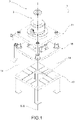
- reference numeral 1 denotes the trimming-deburring assembly object of the present invention as a whole.
- the trimming-deburring assembly 1 is suitable for performing operations for manufacturing a piece starting from a casting, performing cutting operations of parts to be discarded from the casting, for example, sprues, cast runners, wells, vacuum branches, foundry burrs and/or similar.
- the trimming-deburring assembly 1 of the present invention performs these operations by means of a trimming-deburring die 900 which is specially mounted on and moved by the trimming-deburring assembly 1.
- the trimming-deburring die 900 comprising an upper movable die half 901 and a lower fixed die half 902.
- the present invention is not limited in any way to the shape and type of trimming-deburring die 900 and/or die halves.
- the trimming-deburring assembly 1 comprises a plurality of fixed plates (or planes), i.e. having a fixed axial position, and movable, i.e. having an axial position which varies over time according to the configuration in which the trimming-deburring assembly 1 is controlled.
- the trimming-deburring assembly 1 comprises an upper fixed plate 11 and a lower fixed plate 12.
- the lower fixed die half 902 is housable on said lower fixed plate 12.
- the trimming-deburring assembly 1 comprises an intermediate mobile plate 15 which is movable in a vertical direction parallel to a main axis X-X. Said intermediate mobile plate 15 is axially locatedin the space between the upper fixed plate 11 and the lower fixed plate 12. The upper mobile die half 902 is housable on said intermediate mobile plate 15.
- said plates are mutually joined by specific support columns 14, for example four positioned at the four corners of the plates.
- the lower plate 12 and the upper plate 11 are solidly mounted to said support columns 14, while the intermediate mobile plate 15 slides on said columns having specially shaped openings.
- the trimming-deburring assembly 1 comprises command and movement means 2 suitable for moving the intermediate mobile plate 15.
- command and movement means 2 suitable for moving the intermediate mobile plate 15.
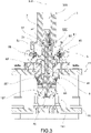
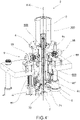
- command and movement means 2 comprise an electric motor 3 and a movement group 4 operatively connected on top to the electric motor 3 and on the bottom to the intermediate mobile plate 15 suitable for receiving the rotary action of the electric motor 3 and converting it into a translational action of the intermediate mobile plate 15.
- the electric motor 3 is housed on the upper fixed plate 11.
- the electric motor 3 is located in another place and engages the movement group 4 by means of a specially provided transmission assembly.
- the movement in the axial direction of the intermediate movable plate 15 is therefore exclusively electrically operated on command of the electric motor 3 through the movement group 4.
- the electric motor 3 is described in detail below, but the movement group 4 is described first.
- the movement group 4 comprises a spindle member 5 drivable in rotation about said main axis X-X by the electric motor 3.
- Said spindle member 5 comprises a spindle cavity 500 along the main axis X-X and comprises a worm gear element 6 equipped with a worm gear cavity 600 defined by a threaded worm gear wall 61.
- said spindle member 500 the electric motor 3 at an upper end thereof and comprises the worm gear element 6 in a lower portion thereof.
- the worm gear element 6 is axially positioned in a lower position than the spindle member 5, i.e. in a proximal position with respect to the intermediate movable plate 15.
- the spindle member 5 and therefore also the worm gear element 6 comprised therein have a substantially defined and fixed axial position being however free to rotate.
- the movement group 4 comprises a worm screw element 7 which extends along the main axis X-X comprising a lower end 70 operatively connected to the intermediate movable late 15 in such a way that the axial movement of the worm screw element 7 involves the variation of the height of the intermediate movable plate 15.
- the trimming-deburring assembly 1 also comprises a connecting structure 151 integrally connected to the intermediate mobile plate 15 engageable axially in a rotationally free manner by the end 70 of the worm screw element 7.
- the connecting structure 151 is also suitable for transmitting the localized axial action of the end 70 to a wider portion of the intermediate mobile plate 15.
- the connecting structure 151 comprises two mutually axially spaced connection plate-shaped elements (the first engaged to the end 70 and the second to the intermediate mobile plate 15) joined together by means of guiding column elements.
- the worm screw element 7 houses at least partially in the spindle cavity 500 and in the worm gear cavity 600, having a threaded screw wall 71 engaged with the threaded worm gear wall 61 so as to receive the rotary action of the worm gear element 6.
- the threaded screw wall 71 is the “screw” while the threaded worm gear wall 61 is the “nut screw”.
- the threaded screw wall 71 and the threaded worm gear wall 61, specially shaped to complement it, are of the multi-start threaded type.
- the threaded screw wall 71 and the threaded worm gear wall 61 are two-start type.
- the threaded screw wall 71 and the threaded worm gear wall 61 have a square pitch.
- the threaded screw wall 71 and the threaded worm gear wall 61 are "long pitch", for example they have pitch 50.
- the threaded screw wall 71 in each axial configuration (i.e. axial height) of the worm screw element 7, has a plurality of ridges in engagement on the threaded worm gear wall 61.
- the threaded screw wall 71 always has ten ridges on engagement on the threaded worm gear wall 61.
- the spindle member 5 comprises a main hub 50, essentially cylindrical and tubular in shape, engaged on top to the electric motor 3 and on the bottom to the worm gear element 6.
- the electric motor 3 controls said main hub 50 in rotation, which by mounting the worm gear element 6 at the lower end thereof, in turn controls it in rotation.
- the main hub 50 consists of a plurality of components.
- the main hub 50 comprises an upper joint 51 directly connected to the electric motor 3 and a spindle shaft 52 directly connected with the worm gear element 6.
- the upper joint 51 and the spindle shaft 52 are at least partially inserted one into the other along the main axis X-X in such a way that the action of the electric motor 3 at the upper joint 51 is transmitted to the spindle shaft 52.
- the upper joint 51 and the spindle shaft 52 have a substantially cylindrical shape.
- the upper joint 51 and the spindle shaft 52 are mutually radially engaged with each other by a geometric coupling.
- the two half-joints have mutually facing walls of complementary shape: in a preferred embodiment, the upper joint 51 and the spindle shaft 52 are geometrically coupled respectively, having protruding portions and housing cavities extending parallel to the main axis X-X.
- the upper joint 51 and the spindle shaft 52 are geometrically coupled by axial grooves.
- the coupling between the upper joint 51 and the spindle shaft 52 only transmits a rotary action. In fact, no possible actions in the axial direction are transmitted between the upper joint 51 and the spindle shaft 52.
- the upper joint 51 is suitable for sliding axially inside the spindle shaft 52.
- the upper joint 51 comprises a motor-side half-joint 51', operatively connected to the electric motor 3, and a shaft-side half-joint 51" operatively connected to the spindle shaft 52.
- the motor-side half-joint 51' is substantially a flanged component which can be mounted on the rotor of the electric motor, while the shaft-side half-joint 51" has a hollow cylindrical grooved shape, for housing and engaging the spindle shaft 52 (in turn hollow, housing the spindle cavity 500).
- the motor-side half-joint 51' and the shaft-side half-joint 51" are joined together by screws.
- the movement group 4 is substantially supported by the upper fixed plate 11.
- the various components described above are supported by said upper fixed plate 11.
- the spindle member 5 extends in length through the fixed plate 11, i.e. in a through opening specifically provided therein, preferably at the main axis X-X.
- the worm gear element 6 and the electric motor 3 are in a lower axial position and in an upper axial position, respectively, with respect to the fixed plane 11.
- the movement group 4 comprises a support device 8 suitable for supporting the spindle member 5 on the upper plate 11.
- the support device 8 comprises a support body 81 fixed to the upper plate 11 and rotation means 85 interposed between the support body 81 and the spindle member 5.
- rotation means 85 By the rotation means 85, the relative rotation of the spindle member with respect to the support body 81 is therefore allowed.
- the rotation means 85 comprise a couple of bearings 85', 85", suitable for supporting and unloading actions in the axial direction and in a radial direction with respect to the main axis X-X on the fixed plate 11, through the support body 81.
- the two bearings 85', 85" are positioned on the two sides of the fixed plate 11 operating in a mutually opposite manner.
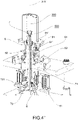
- the movement group 4 comprises a safety device 9 which engages the spindle member 5 to lock and/or brake the rotating action and therefore the movement of the worm screw element 7.
- the safety device 9 is suitable for intervening to keep the intermediate mobile plate 15 in a raised safety position.
- the intermediate mobile plate 15 raised safely, it is possible to carry out operations to change the die, that is to say, to equip or maintain the die.
- the safety device 9 comprises a disc element 90 integrally connected to the spindle member 5 in such a way that it rotates therewith, wherein the disc element 90 has a substantially radial extension with respect to the main axis X-X.
- the safety device 9 comprises at least one gripper device 95 suitable for gripping the disc element 90 to lock and/or brake the rotation thereof.
- the safety device 9 comprises a plurality of gripper devices 95, for example two, mutually angularly equidistant with respect to the main axis X-X.
- the spindle member 5 in the spindle cavity 500 is suitable for containing a lubricating element suitable for lubricating the movement of the worm screw element 7 with the worm gear element 6.
- the same spindle member 5, in particular in the spindle cavity 500 acts as a lubricant storage.
- the same worm screw element 7 comprises suitable ducts which allow the passage of the lubricant so as to keep the entire threaded screw wall 71 and also the threaded worm gear wall 61 lubricated.
- at the lower end 70 preferably at the connection structure 151, there is a lubricant collection body 157 suitable for collecting a predefined quantity of lubricant at the bottom.
- the electric motor 3 is of the hollow type.
- the electric motor 3 therefore comprises a motor cavity 300 which extends along the main axis X-X.
- the movement group 4, and in particular the worm screw element 7 and/or the spindle member 5 are at least partially housed.
- the electric motor 3 is of the internal rotor type.
- the spindle member 5, in particular the upper joint 51, in particular the motor-side half-joint 51', are integrally connected with said internal rotor to rotate simultaneously therewith.
- the electric motor 3 is of the direct torque type, and therefore does not require a reducer to transmit the motion to the movement group 4.
- the electric motor 3 accumulates energy in the descent operations of the intermediate mobile plate 15 and uses said stored energy to perform the ascending operations of the intermediate mobile plate 15 upwards.
- the accumulated energy can also be used for other members or components of the trimming-deburring assembly 1 or it can be used as an electrical supply for other components external to the trimming-deburring assembly 1.
- the electric motor 3 starts at the moment of the start of the movement starting from a configuration with intermediate mobile plate 15 in a raised position, while the rest of the descent is due to the mass of the upper movable die half 902 and of the intermediate mobile plate 15, thus taking place by inertia.
- the electric motor 3 also intervenes in the final steps of the axial descent movement corresponding to the trimming of the casting. In other words, the electric motor intervenes only when the power supply is exclusively necessary.
- the trimming-deburring assembly 1 comprises a pneumatic supply device 19 of said radial die carriage 950.
- said pneumatic supply device 19 is housed on the intermediate mobile plate 15 and/or on the lower fixed plate 12.
- the pneumatic supply device 19 comprising an apparatus for multiplying the pressure of the compressed air, for example suitable for bringing the air under pressure up to 30/40 bar (or 3/4kPa) .
- the trimming-deburring assembly 1 is suitable for fully fulfilling the intended purpose.
- the trimming-deburring assembly overcomes the problems related to the hydraulic movement of the components by presenting an innovative mode of electric only movement.
- the trimming-deburring assembly is suitable for accumulating electrical energy by exploiting the inertia of the descent operations.
- the trimming-deburring assembly operates with a high energy saving with respect to the known solutions.
- it performs a high energy saving also with reference to the hydraulically operated solutions in which it is anyway necessary to supply electricity to control the hydraulic plant.
- the trimming-deburring assembly manages energy consumption in such a way as to limit the power supply of the electric motor only and exclusively to the steps in which it is necessary.
- the trimming-deburring assembly does not require particular maintenance operations.
- the trimming-deburring assembly is particularly clean from circuit-breakers and accessory systems, for example hydraulic systems.
- the trimming-deburring assembly appears to have a particularly clean operating area and not, for example, dirty from oils or oil residues as instead present in the known solutions of the hydraulic actuation prior art.
- the mutual engagement between the worm screw element and the worm gear element allows relatively high axial translations corresponding to relatively short reciprocal rotations.
- the trimming-deburring assembly is designed in such a way as to be compact and contained.
- the trimming-deburring assembly is designed in such a way as to be particularly rigid.
- the trimming-deburring assembly can be designed according to the powers that it must deliver.
- the electric motor and above all the components included in the movement group, in particular the worm screw element can be designed according to the needs and in particular according to the tonnage to be expressed for trimming-deburring operations.
- the trimming-deburring assembly operates in total safety for the people who use it, for example the maintenance personnel and/or the toolmakers.
- the trimming-deburring assembly operates in total safety for the same components that compose it (i.e. the work screw element, the worm gear element) or housed therein (i.e. trimming-deburring dies).
- the trimming-deburring assembly is free from all the elements necessary for hydraulic movement, such as for example pump units, series of solenoid valves, oil cooling units, relative circuitry.
Landscapes
- Engineering & Computer Science (AREA)
- Mechanical Engineering (AREA)
- Moulds For Moulding Plastics Or The Like (AREA)
- Processing And Handling Of Plastics And Other Materials For Molding In General (AREA)
- Milling Processes (AREA)
- Gear Processing (AREA)
- Press Drives And Press Lines (AREA)
Claims (18)
- Ensemble de découpe et ébavurage (1) qui réalise des opérations pour fabriquer une pièce à partir d'une coulée par la réalisation d'opérations de coupe de parties à rejeter de la coulée, par exemple des carottes, des canaux, des puits, des ramifications sous vide, des bavures de fonderie et/ou des éléments similaires, en utilisant une matrice de découpe et ébavurage (900) comprenant une moitié supérieure de matrice mobile (901) et une moitié inférieure de matrice fixe (902), dans lequel l'ensemble de découpe et ébavurage (1) comprend :- une plaque fixe supérieure (11) ;- une plaque fixe inférieure (12) sur laquelle la moitié inférieure de matrice fixe (902) peut être logée ;- une plaque mobile intermédiaire (15) qui est mobile entre la plaque fixe supérieure (11) et la plaque fixe inférieure (12), dans une direction verticale parallèle à un axe principal (X-X), dans lequel la moitié supérieure de matrice mobile (902) peut être logée sur ladite plaque mobile intermédiaire (15) ;- des moyens de commande et de déplacement (2) aptes à déplacer la plaque mobile intermédiaire (15) comprenant :i) un moteur électrique (3) logé sur la plaque fixe supérieure (11) ;ii) un groupe de déplacement (4) relié opérationnellement en haut au moteur électrique (3) et en bas à la plaque mobile intermédiaire (15) comprenant :- un organe de broche (5) pouvant être mis en rotation autour dudit axe principal (X-X) par le moteur électrique (3), comprenant une cavité de broche (500) le long de l'axe principal (X-X) et comprenant un élément d'engrenage à vis sans fin (6) pourvu d'une cavité d'engrenage à vis sans fin (600) définie par une paroi d'engrenage à vis sans fin filetée (61) ;- un élément de vis sans fin (7) qui s'étend le long de l'axe principal (X-X), logé au moins partiellement dans la cavité de broche (500) et la cavité d'engrenage à vis sans fin (600), comprenant une paroi de vis filetée (71) mise en prise avec la paroi d'engrenage à vis sans fin filetée (61) et une extrémité inférieure (70) reliée opérationnellement à la plaque mobile intermédiaire (15), dans lequel la rotation de l'élément d'engrenage à vis sans fin (6) implique un déplacement axial de l'élément de vis sans fin (7) et à tour de rôle un changement de la hauteur de la plaque mobile intermédiaire (15).
- Ensemble de découpe et ébavurage (1) selon la revendication 1, dans lequel la paroi de vis filetée (71) et la paroi d'engrenage à vis sans fin filetée (61), en particulier de formes complémentaires, sont du type à filets multiples.
- Ensemble de découpe et ébavurage (1) selon la revendication 2, dans lequel la paroi de vis filetée (71) et la paroi d'engrenage à vis sans fin filetée (71) sont à deux filets, ayant un pas carré.
- Ensemble de découpe et ébavurage (1) selon la revendication 2 ou 3, dans lequel, dans chaque configuration axiale de l'élément de vis sans fin (7), la paroi de vis filetée (71) comporte une pluralité de nervures en prise sur la paroi d'engrenage à vis sans fin filetée (61), par exemple au moins dix nervures sont toujours en prise.
- Ensemble de découpe et ébavurage (1) selon l'une quelconque des revendications précédentes, dans lequel le moteur électrique (3) est du type creux comprenant une cavité de moteur (300) qui s'étend le long de l'axe principal (X-X) dans laquelle le groupe de déplacement (4), et de préférence l'élément de vis sans fin (7), est au moins partiellement logé.
- Ensemble de découpe et ébavurage (1) selon la revendication 5, dans lequel le moteur électrique (3) comporte un rotor interne de telle manière que l'organe de broche (5) soit relié intégralement audit rotor interne pour tourner simultanément avec celui-ci.
- Ensemble de découpe et ébavurage (1) selon l'une quelconque des revendications précédentes, dans lequel le moteur électrique (3) accumule de l'énergie dans les opérations de descente de la plaque mobile intermédiaire (15) et utilise ladite énergie stockée pour réaliser les opérations de montée de la plaque mobile intermédiaire (15).
- Ensemble de découpe et ébavurage (1) selon l'une quelconque des revendications précédentes, dans lequel l'organe de broche (5) comprend un moyeu principal (50), de forme essentiellement cylindrique et tubulaire, mis en prise en haut avec le moteur électrique (3) et en bas avec l'élément d'engrenage à vis sans fin (6).
- Ensemble de découpe et ébavurage (1) selon la revendication 8, dans lequel le moyeu principal (50) comprend une articulation supérieure (51), reliée directement au moteur électrique (3), et un arbre de broche (52), relié directement à l'élément d'engrenage à vis sans fin (6), dans lequel l'articulation supérieure (51) et l'arbre de broche (52) sont au moins partiellement insérés l'un dans l'autre le long de l'axe principal (X-X) et sont mis radialement en prise l'un avec l'autre au moyen d'un couplage géométrique, de sorte qu'une action exclusivement rotative soit transmise entre l'articulation supérieure (51) et l'arbre de broche (52).
- Ensemble de découpe et ébavurage (1) selon l'une quelconque des revendications précédentes, dans lequel l'organe de broche (5) s'étend en longueur à travers la plaque fixe (11), de manière à présenter l'élément d'engrenage à vis sans fin (6) et le moteur électrique (3) respectivement à une position axiale inférieure et à une position axiale supérieure par rapport à la plaque fixe (11).
- Ensemble de découpe et ébavurage (1) selon la revendication 10, dans lequel le groupe de déplacement (4) comprend un dispositif de support (8) apte à supporter l'organe de broche (5) sur la plaque supérieure (11), dans lequel le dispositif de support (8) comprend un corps de support (81) fixé à la plaque supérieure (11) et des moyens de rotation (85) interposés entre le corps de support (81) et l'organe de broche (5).
- Ensemble de découpe et ébavurage (1) selon la revendication 11, dans lequel les moyens de rotation (85) comprennent un couple de paliers (85', 85") positionnés des deux côtés de la plaque fixe (11), aptes à des actions de support et de déchargement dans la direction axiale et dans la direction radiale par rapport à l'axe principal (X-X) sur ladite plaque fixe (11).
- Ensemble de découpe et ébavurage (1) selon l'une quelconque des revendications précédentes, dans lequel le groupe de déplacement (4) comprend un dispositif de sécurité (9) qui se met en prise avec l'organe de broche (5) pour verrouiller et/ou freiner l'action de rotation et par conséquent le déplacement de l'élément de vis sans fin (7).
- Ensemble de découpe et ébavurage (1) selon la revendication 13, dans lequel le dispositif de sécurité (9) comprend :- un élément de disque (90) relié intégralement à l'organe de broche (5) de manière à tourner avec celui-ci, dans lequel l'élément de disque (90) comporte une extension sensiblement radiale par rapport à l'axe principal (X-X) ; et- au moins un dispositif de préhension (95) apte à prendre l'élément de disque (90) pour verrouiller et/ou freiner la rotation de celui-ci.
- Ensemble de découpe et ébavurage (1) selon l'une quelconque des revendications précédentes, dans lequel l'élément d'engrenage à vis sans fin (6) est positionné axialement à une position plus basse que l'organe de broche (5), c'est-à-dire à une position proximale par rapport à la plaque mobile intermédiaire (15).
- Ensemble de découpe et ébavurage (1) selon l'une quelconque des revendications précédentes, dans lequel l'organe de broche (5) dans la cavité de broche (500) est apte à contenir un élément de lubrification apte à lubrifier le déplacement de l'élément de vis sans fin (7) avec l'élément d'engrenage à vis sans fin (6).
- Ensemble de découpe et ébavurage (1) selon l'une quelconque des revendications précédentes, comprenant également une structure de liaison (151) reliée intégralement à la plaque mobile intermédiaire (15) pouvant être mise en prise axialement, d'une manière sans rotation, par l'extrémité (70) de l'élément de vis sans fin (7).
- Ensemble de découpe et ébavurage (1) selon l'une quelconque des revendications précédentes, dans lequel la moitié supérieure de matrice mobile (901) et/ou la moitié inférieure de matrice fixe (902) comprend au moins un chariot radial de matrice (950), dans lequel l'ensemble de découpe et ébavurage (1) comprend, logé sur la plaque mobile intermédiaire (15) et/ou sur la plaque fixe inférieure (12), un dispositif d'alimentation pneumatique (19) dudit chariot radial de matrice (950) comprenant un appareil pour multiplier la pression d'air comprimé.
Applications Claiming Priority (2)
| Application Number | Priority Date | Filing Date | Title |
|---|---|---|---|
| IT201800007057 | 2018-07-10 | ||
| PCT/IB2019/054724 WO2020012264A1 (fr) | 2018-07-10 | 2019-06-06 | Ensemble d'ébavurage et d'ébarbage |
Publications (2)
| Publication Number | Publication Date |
|---|---|
| EP3820635A1 EP3820635A1 (fr) | 2021-05-19 |
| EP3820635B1 true EP3820635B1 (fr) | 2022-07-06 |
Family
ID=63834395
Family Applications (1)
| Application Number | Title | Priority Date | Filing Date |
|---|---|---|---|
| EP19737242.8A Active EP3820635B1 (fr) | 2018-07-10 | 2019-06-06 | Ensemble de découpe et ébavurage |
Country Status (6)
| Country | Link |
|---|---|
| US (1) | US11433454B2 (fr) |
| EP (1) | EP3820635B1 (fr) |
| JP (1) | JP7343193B2 (fr) |
| ES (1) | ES2928310T3 (fr) |
| MX (1) | MX2020013577A (fr) |
| WO (1) | WO2020012264A1 (fr) |
Families Citing this family (4)
| Publication number | Priority date | Publication date | Assignee | Title |
|---|---|---|---|---|
| CN111633201A (zh) * | 2020-06-11 | 2020-09-08 | 韩才壑 | 一种方便操作的铸造件清洗装置 |
| IT202000023728A1 (it) * | 2020-10-08 | 2022-04-08 | Mecc Pi Erre S R L Di Pederzoli Ruggero & C | Sistema di stampaggio |
| CN113770325B (zh) * | 2021-08-03 | 2023-01-10 | 株洲市四兴机械有限公司 | 一种压铸生产线 |
| KR102372944B1 (ko) * | 2021-11-16 | 2022-03-10 | 최상진 | 다중제어 밸브 주물용 내부 숏 블라스트 장치 |
Family Cites Families (7)
| Publication number | Priority date | Publication date | Assignee | Title |
|---|---|---|---|---|
| JP3748992B2 (ja) * | 1997-07-07 | 2006-02-22 | 東洋機械金属株式会社 | 射出成形機 |
| EP1101593B1 (fr) * | 1997-07-07 | 2004-09-15 | Toyo Machinery & Metal Co. Ltd. | Machine à mouler par injection actionnée électriquement et procédé de moulage par injection |
| JP3406561B2 (ja) * | 2000-03-21 | 2003-05-12 | 住友重機械工業株式会社 | 射出成形機の製品突出し装置 |
| JP3811650B2 (ja) * | 2002-01-29 | 2006-08-23 | 住友重機械工業株式会社 | 射出成形機の潤滑装置 |
| DE10222748C1 (de) | 2002-05-23 | 2003-05-28 | Demag Ergotech Gmbh | Einspritzaggregat für eine Spritzgießmaschine |
| JP4198010B2 (ja) * | 2003-08-20 | 2008-12-17 | 東洋機械金属株式会社 | 電動式射出成形機 |
| JP2006312195A (ja) * | 2005-05-09 | 2006-11-16 | Farukomu:Kk | ワーク処理方法及びワーク処理装置 |
-
2019
- 2019-06-06 JP JP2020570564A patent/JP7343193B2/ja active Active
- 2019-06-06 US US16/973,469 patent/US11433454B2/en active Active
- 2019-06-06 MX MX2020013577A patent/MX2020013577A/es unknown
- 2019-06-06 EP EP19737242.8A patent/EP3820635B1/fr active Active
- 2019-06-06 WO PCT/IB2019/054724 patent/WO2020012264A1/fr unknown
- 2019-06-06 ES ES19737242T patent/ES2928310T3/es active Active
Also Published As
| Publication number | Publication date |
|---|---|
| WO2020012264A1 (fr) | 2020-01-16 |
| US11433454B2 (en) | 2022-09-06 |
| MX2020013577A (es) | 2021-02-26 |
| JP2021524381A (ja) | 2021-09-13 |
| ES2928310T3 (es) | 2022-11-17 |
| JP7343193B2 (ja) | 2023-09-12 |
| EP3820635A1 (fr) | 2021-05-19 |
| US20210229168A1 (en) | 2021-07-29 |
Similar Documents
| Publication | Publication Date | Title |
|---|---|---|
| EP3820635B1 (fr) | Ensemble de découpe et ébavurage | |
| CN107717909A (zh) | 一种用于模具制造的升降式工作平台 | |
| CN100515597C (zh) | 模具缓冲装置 | |
| CN111283131B (zh) | 一种锻造液压机辅助夹持装置 | |
| CN102765677A (zh) | 具有弹簧平衡设计的电动升降台 | |
| CN2902522Y (zh) | 热模锻压力机装模高度调节及解脱闷车装置 | |
| CN108436772A (zh) | 一种用于机器人打磨抛光的智能砂纸更换装置 | |
| CN108670603A (zh) | 一种传动装置及电动轮椅 | |
| CN102794918B (zh) | 一种电动螺旋压力机 | |
| CN110624995A (zh) | 一种落料方便的冲压模具 | |
| CN109130014A (zh) | 一种自动脱模的油烟机模具 | |
| CN201416520Y (zh) | 一种星形排列柱塞式无级变量泵 | |
| JP4783182B2 (ja) | プレス機械 | |
| EP3362401B1 (fr) | Mécanisme de pompage comprenant un système électromécanique de levage | |
| CN207494612U (zh) | 一种多功能消防阀门加工机床 | |
| CN211638071U (zh) | 一种铝型材冲压模具 | |
| CN215657780U (zh) | 飞轮壳自动下砂芯装置 | |
| CN111390834A (zh) | 电动顶杆装置 | |
| CN210412093U (zh) | 一种精密压力机 | |
| CN219852214U (zh) | 一种用于螺母压铸成型的锌合金压铸模具 | |
| CN217508487U (zh) | 升降电机 | |
| CN103707540B (zh) | 离合器螺旋压力机 | |
| CN113427810A (zh) | 一种改进型闭式四点压力机 | |
| CN220462949U (zh) | 自锁式转台 | |
| CN115045833B (zh) | 一种双螺杆三星轮压缩机 |
Legal Events
| Date | Code | Title | Description |
|---|---|---|---|
| STAA | Information on the status of an ep patent application or granted ep patent |
Free format text: STATUS: UNKNOWN |
|
| STAA | Information on the status of an ep patent application or granted ep patent |
Free format text: STATUS: THE INTERNATIONAL PUBLICATION HAS BEEN MADE |
|
| STAA | Information on the status of an ep patent application or granted ep patent |
Free format text: STATUS: THE INTERNATIONAL PUBLICATION HAS BEEN MADE |
|
| PUAI | Public reference made under article 153(3) epc to a published international application that has entered the european phase |
Free format text: ORIGINAL CODE: 0009012 |
|
| STAA | Information on the status of an ep patent application or granted ep patent |
Free format text: STATUS: REQUEST FOR EXAMINATION WAS MADE |
|
| 17P | Request for examination filed |
Effective date: 20201204 |
|
| AK | Designated contracting states |
Kind code of ref document: A1 Designated state(s): AL AT BE BG CH CY CZ DE DK EE ES FI FR GB GR HR HU IE IS IT LI LT LU LV MC MK MT NL NO PL PT RO RS SE SI SK SM TR |
|
| DAV | Request for validation of the european patent (deleted) | ||
| DAX | Request for extension of the european patent (deleted) | ||
| GRAP | Despatch of communication of intention to grant a patent |
Free format text: ORIGINAL CODE: EPIDOSNIGR1 |
|
| STAA | Information on the status of an ep patent application or granted ep patent |
Free format text: STATUS: GRANT OF PATENT IS INTENDED |
|
| INTG | Intention to grant announced |
Effective date: 20220202 |
|
| GRAS | Grant fee paid |
Free format text: ORIGINAL CODE: EPIDOSNIGR3 |
|
| GRAA | (expected) grant |
Free format text: ORIGINAL CODE: 0009210 |
|
| STAA | Information on the status of an ep patent application or granted ep patent |
Free format text: STATUS: THE PATENT HAS BEEN GRANTED |
|
| AK | Designated contracting states |
Kind code of ref document: B1 Designated state(s): AL AT BE BG CH CY CZ DE DK EE ES FI FR GB GR HR HU IE IS IT LI LT LU LV MC MK MT NL NO PL PT RO RS SE SI SK SM TR |
|
| REG | Reference to a national code |
Ref country code: AT Ref legal event code: REF Ref document number: 1502504 Country of ref document: AT Kind code of ref document: T Effective date: 20220715 Ref country code: CH Ref legal event code: EP |
|
| REG | Reference to a national code |
Ref country code: DE Ref legal event code: R096 Ref document number: 602019016760 Country of ref document: DE |
|
| REG | Reference to a national code |
Ref country code: IE Ref legal event code: FG4D |
|
| REG | Reference to a national code |
Ref country code: LT Ref legal event code: MG9D |
|
| REG | Reference to a national code |
Ref country code: NL Ref legal event code: MP Effective date: 20220706 |
|
| REG | Reference to a national code |
Ref country code: ES Ref legal event code: FG2A Ref document number: 2928310 Country of ref document: ES Kind code of ref document: T3 Effective date: 20221117 |
|
| PG25 | Lapsed in a contracting state [announced via postgrant information from national office to epo] |
Ref country code: SE Free format text: LAPSE BECAUSE OF FAILURE TO SUBMIT A TRANSLATION OF THE DESCRIPTION OR TO PAY THE FEE WITHIN THE PRESCRIBED TIME-LIMIT Effective date: 20220706 Ref country code: RS Free format text: LAPSE BECAUSE OF FAILURE TO SUBMIT A TRANSLATION OF THE DESCRIPTION OR TO PAY THE FEE WITHIN THE PRESCRIBED TIME-LIMIT Effective date: 20220706 Ref country code: PT Free format text: LAPSE BECAUSE OF FAILURE TO SUBMIT A TRANSLATION OF THE DESCRIPTION OR TO PAY THE FEE WITHIN THE PRESCRIBED TIME-LIMIT Effective date: 20221107 Ref country code: NO Free format text: LAPSE BECAUSE OF FAILURE TO SUBMIT A TRANSLATION OF THE DESCRIPTION OR TO PAY THE FEE WITHIN THE PRESCRIBED TIME-LIMIT Effective date: 20221006 Ref country code: NL Free format text: LAPSE BECAUSE OF FAILURE TO SUBMIT A TRANSLATION OF THE DESCRIPTION OR TO PAY THE FEE WITHIN THE PRESCRIBED TIME-LIMIT Effective date: 20220706 Ref country code: LV Free format text: LAPSE BECAUSE OF FAILURE TO SUBMIT A TRANSLATION OF THE DESCRIPTION OR TO PAY THE FEE WITHIN THE PRESCRIBED TIME-LIMIT Effective date: 20220706 Ref country code: LT Free format text: LAPSE BECAUSE OF FAILURE TO SUBMIT A TRANSLATION OF THE DESCRIPTION OR TO PAY THE FEE WITHIN THE PRESCRIBED TIME-LIMIT Effective date: 20220706 Ref country code: FI Free format text: LAPSE BECAUSE OF FAILURE TO SUBMIT A TRANSLATION OF THE DESCRIPTION OR TO PAY THE FEE WITHIN THE PRESCRIBED TIME-LIMIT Effective date: 20220706 |
|
| REG | Reference to a national code |
Ref country code: AT Ref legal event code: MK05 Ref document number: 1502504 Country of ref document: AT Kind code of ref document: T Effective date: 20220706 |
|
| PG25 | Lapsed in a contracting state [announced via postgrant information from national office to epo] |
Ref country code: PL Free format text: LAPSE BECAUSE OF FAILURE TO SUBMIT A TRANSLATION OF THE DESCRIPTION OR TO PAY THE FEE WITHIN THE PRESCRIBED TIME-LIMIT Effective date: 20220706 Ref country code: IS Free format text: LAPSE BECAUSE OF FAILURE TO SUBMIT A TRANSLATION OF THE DESCRIPTION OR TO PAY THE FEE WITHIN THE PRESCRIBED TIME-LIMIT Effective date: 20221106 Ref country code: HR Free format text: LAPSE BECAUSE OF FAILURE TO SUBMIT A TRANSLATION OF THE DESCRIPTION OR TO PAY THE FEE WITHIN THE PRESCRIBED TIME-LIMIT Effective date: 20220706 Ref country code: GR Free format text: LAPSE BECAUSE OF FAILURE TO SUBMIT A TRANSLATION OF THE DESCRIPTION OR TO PAY THE FEE WITHIN THE PRESCRIBED TIME-LIMIT Effective date: 20221007 |
|
| REG | Reference to a national code |
Ref country code: DE Ref legal event code: R097 Ref document number: 602019016760 Country of ref document: DE |
|
| PG25 | Lapsed in a contracting state [announced via postgrant information from national office to epo] |
Ref country code: SM Free format text: LAPSE BECAUSE OF FAILURE TO SUBMIT A TRANSLATION OF THE DESCRIPTION OR TO PAY THE FEE WITHIN THE PRESCRIBED TIME-LIMIT Effective date: 20220706 Ref country code: RO Free format text: LAPSE BECAUSE OF FAILURE TO SUBMIT A TRANSLATION OF THE DESCRIPTION OR TO PAY THE FEE WITHIN THE PRESCRIBED TIME-LIMIT Effective date: 20220706 Ref country code: DK Free format text: LAPSE BECAUSE OF FAILURE TO SUBMIT A TRANSLATION OF THE DESCRIPTION OR TO PAY THE FEE WITHIN THE PRESCRIBED TIME-LIMIT Effective date: 20220706 Ref country code: CZ Free format text: LAPSE BECAUSE OF FAILURE TO SUBMIT A TRANSLATION OF THE DESCRIPTION OR TO PAY THE FEE WITHIN THE PRESCRIBED TIME-LIMIT Effective date: 20220706 Ref country code: AT Free format text: LAPSE BECAUSE OF FAILURE TO SUBMIT A TRANSLATION OF THE DESCRIPTION OR TO PAY THE FEE WITHIN THE PRESCRIBED TIME-LIMIT Effective date: 20220706 |
|
| PLBE | No opposition filed within time limit |
Free format text: ORIGINAL CODE: 0009261 |
|
| STAA | Information on the status of an ep patent application or granted ep patent |
Free format text: STATUS: NO OPPOSITION FILED WITHIN TIME LIMIT |
|
| PG25 | Lapsed in a contracting state [announced via postgrant information from national office to epo] |
Ref country code: SK Free format text: LAPSE BECAUSE OF FAILURE TO SUBMIT A TRANSLATION OF THE DESCRIPTION OR TO PAY THE FEE WITHIN THE PRESCRIBED TIME-LIMIT Effective date: 20220706 Ref country code: EE Free format text: LAPSE BECAUSE OF FAILURE TO SUBMIT A TRANSLATION OF THE DESCRIPTION OR TO PAY THE FEE WITHIN THE PRESCRIBED TIME-LIMIT Effective date: 20220706 |
|
| 26N | No opposition filed |
Effective date: 20230411 |
|
| P01 | Opt-out of the competence of the unified patent court (upc) registered |
Effective date: 20230508 |
|
| PG25 | Lapsed in a contracting state [announced via postgrant information from national office to epo] |
Ref country code: AL Free format text: LAPSE BECAUSE OF FAILURE TO SUBMIT A TRANSLATION OF THE DESCRIPTION OR TO PAY THE FEE WITHIN THE PRESCRIBED TIME-LIMIT Effective date: 20220706 |
|
| PG25 | Lapsed in a contracting state [announced via postgrant information from national office to epo] |
Ref country code: SI Free format text: LAPSE BECAUSE OF FAILURE TO SUBMIT A TRANSLATION OF THE DESCRIPTION OR TO PAY THE FEE WITHIN THE PRESCRIBED TIME-LIMIT Effective date: 20220706 |
|
| PGFP | Annual fee paid to national office [announced via postgrant information from national office to epo] |
Ref country code: TR Payment date: 20230918 Year of fee payment: 5 Ref country code: GB Payment date: 20230920 Year of fee payment: 5 Ref country code: ES Payment date: 20230918 Year of fee payment: 5 |
|
| PGFP | Annual fee paid to national office [announced via postgrant information from national office to epo] |
Ref country code: FR Payment date: 20230929 Year of fee payment: 5 Ref country code: DE Payment date: 20230920 Year of fee payment: 5 |
|
| PG25 | Lapsed in a contracting state [announced via postgrant information from national office to epo] |
Ref country code: MC Free format text: LAPSE BECAUSE OF FAILURE TO SUBMIT A TRANSLATION OF THE DESCRIPTION OR TO PAY THE FEE WITHIN THE PRESCRIBED TIME-LIMIT Effective date: 20220706 |
|
| PG25 | Lapsed in a contracting state [announced via postgrant information from national office to epo] |
Ref country code: MC Free format text: LAPSE BECAUSE OF FAILURE TO SUBMIT A TRANSLATION OF THE DESCRIPTION OR TO PAY THE FEE WITHIN THE PRESCRIBED TIME-LIMIT Effective date: 20220706 |
|
| PGFP | Annual fee paid to national office [announced via postgrant information from national office to epo] |
Ref country code: IT Payment date: 20230927 Year of fee payment: 5 Ref country code: CH Payment date: 20231108 Year of fee payment: 5 |
|
| REG | Reference to a national code |
Ref country code: BE Ref legal event code: MM Effective date: 20230630 |
|
| PG25 | Lapsed in a contracting state [announced via postgrant information from national office to epo] |
Ref country code: LU Free format text: LAPSE BECAUSE OF NON-PAYMENT OF DUE FEES Effective date: 20230606 |
|
| REG | Reference to a national code |
Ref country code: IE Ref legal event code: MM4A |
|
| PG25 | Lapsed in a contracting state [announced via postgrant information from national office to epo] |
Ref country code: LU Free format text: LAPSE BECAUSE OF NON-PAYMENT OF DUE FEES Effective date: 20230606 |
|
| PG25 | Lapsed in a contracting state [announced via postgrant information from national office to epo] |
Ref country code: IE Free format text: LAPSE BECAUSE OF NON-PAYMENT OF DUE FEES Effective date: 20230606 |
|
| PG25 | Lapsed in a contracting state [announced via postgrant information from national office to epo] |
Ref country code: IE Free format text: LAPSE BECAUSE OF NON-PAYMENT OF DUE FEES Effective date: 20230606 |