EP3819769B1 - Klimaregelungssystem und klimaanlage oder klimatisierungssystem - Google Patents
Klimaregelungssystem und klimaanlage oder klimatisierungssystem Download PDFInfo
- Publication number
- EP3819769B1 EP3819769B1 EP19910476.1A EP19910476A EP3819769B1 EP 3819769 B1 EP3819769 B1 EP 3819769B1 EP 19910476 A EP19910476 A EP 19910476A EP 3819769 B1 EP3819769 B1 EP 3819769B1
- Authority
- EP
- European Patent Office
- Prior art keywords
- control unit
- devices
- sub communication
- additional function
- air conditioning
- Prior art date
- Legal status (The legal status is an assumption and is not a legal conclusion. Google has not performed a legal analysis and makes no representation as to the accuracy of the status listed.)
- Active
Links
Images


Classifications
-
- F—MECHANICAL ENGINEERING; LIGHTING; HEATING; WEAPONS; BLASTING
- F24—HEATING; RANGES; VENTILATING
- F24F—AIR-CONDITIONING; AIR-HUMIDIFICATION; VENTILATION; USE OF AIR CURRENTS FOR SCREENING
- F24F11/00—Control or safety arrangements
- F24F11/50—Control or safety arrangements characterised by user interfaces or communication
- F24F11/54—Control or safety arrangements characterised by user interfaces or communication using one central controller connected to several sub-controllers
-
- F—MECHANICAL ENGINEERING; LIGHTING; HEATING; WEAPONS; BLASTING
- F24—HEATING; RANGES; VENTILATING
- F24F—AIR-CONDITIONING; AIR-HUMIDIFICATION; VENTILATION; USE OF AIR CURRENTS FOR SCREENING
- F24F11/00—Control or safety arrangements
- F24F11/50—Control or safety arrangements characterised by user interfaces or communication
-
- F—MECHANICAL ENGINEERING; LIGHTING; HEATING; WEAPONS; BLASTING
- F24—HEATING; RANGES; VENTILATING
- F24F—AIR-CONDITIONING; AIR-HUMIDIFICATION; VENTILATION; USE OF AIR CURRENTS FOR SCREENING
- F24F11/00—Control or safety arrangements
- F24F11/30—Control or safety arrangements for purposes related to the operation of the system, e.g. for safety or monitoring
- F24F11/32—Responding to malfunctions or emergencies
- F24F11/38—Failure diagnosis
-
- F—MECHANICAL ENGINEERING; LIGHTING; HEATING; WEAPONS; BLASTING
- F24—HEATING; RANGES; VENTILATING
- F24F—AIR-CONDITIONING; AIR-HUMIDIFICATION; VENTILATION; USE OF AIR CURRENTS FOR SCREENING
- F24F11/00—Control or safety arrangements
- F24F11/62—Control or safety arrangements characterised by the type of control or by internal processing, e.g. using fuzzy logic, adaptive control or estimation of values
- F24F11/63—Electronic processing
-
- F—MECHANICAL ENGINEERING; LIGHTING; HEATING; WEAPONS; BLASTING
- F24—HEATING; RANGES; VENTILATING
- F24F—AIR-CONDITIONING; AIR-HUMIDIFICATION; VENTILATION; USE OF AIR CURRENTS FOR SCREENING
- F24F11/00—Control or safety arrangements
- F24F11/88—Electrical aspects, e.g. circuits
-
- G—PHYSICS
- G06—COMPUTING OR CALCULATING; COUNTING
- G06F—ELECTRIC DIGITAL DATA PROCESSING
- G06F11/00—Error detection; Error correction; Monitoring
- G06F11/07—Responding to the occurrence of a fault, e.g. fault tolerance
- G06F11/0703—Error or fault processing not based on redundancy, i.e. by taking additional measures to deal with the error or fault not making use of redundancy in operation, in hardware, or in data representation
- G06F11/0706—Error or fault processing not based on redundancy, i.e. by taking additional measures to deal with the error or fault not making use of redundancy in operation, in hardware, or in data representation the processing taking place on a specific hardware platform or in a specific software environment
- G06F11/0736—Error or fault processing not based on redundancy, i.e. by taking additional measures to deal with the error or fault not making use of redundancy in operation, in hardware, or in data representation the processing taking place on a specific hardware platform or in a specific software environment in functional embedded systems, i.e. in a data processing system designed as a combination of hardware and software dedicated to performing a certain function
-
- G—PHYSICS
- G06—COMPUTING OR CALCULATING; COUNTING
- G06F—ELECTRIC DIGITAL DATA PROCESSING
- G06F11/00—Error detection; Error correction; Monitoring
- G06F11/07—Responding to the occurrence of a fault, e.g. fault tolerance
- G06F11/0703—Error or fault processing not based on redundancy, i.e. by taking additional measures to deal with the error or fault not making use of redundancy in operation, in hardware, or in data representation
- G06F11/0751—Error or fault detection not based on redundancy
-
- G—PHYSICS
- G06—COMPUTING OR CALCULATING; COUNTING
- G06F—ELECTRIC DIGITAL DATA PROCESSING
- G06F11/00—Error detection; Error correction; Monitoring
- G06F11/07—Responding to the occurrence of a fault, e.g. fault tolerance
- G06F11/0703—Error or fault processing not based on redundancy, i.e. by taking additional measures to deal with the error or fault not making use of redundancy in operation, in hardware, or in data representation
- G06F11/079—Root cause analysis, i.e. error or fault diagnosis
-
- G—PHYSICS
- G06—COMPUTING OR CALCULATING; COUNTING
- G06F—ELECTRIC DIGITAL DATA PROCESSING
- G06F11/00—Error detection; Error correction; Monitoring
- G06F11/07—Responding to the occurrence of a fault, e.g. fault tolerance
- G06F11/0703—Error or fault processing not based on redundancy, i.e. by taking additional measures to deal with the error or fault not making use of redundancy in operation, in hardware, or in data representation
- G06F11/0793—Remedial or corrective actions
Definitions
- the present disclosure relates to environment control systems, and air conditioners or air conditioning systems.
- Patent Literature 2 describes an HVAC data processing and communication network and a method of manufacturing the same, including a system device and a subnet controller.
- Patent Literature 3 describes a HVAC system provided with control communication over a serial data bus.
- Patent Literature 4 discloses a system and method for identifying a failed storage device in a storage system comprising a plurality of storage devices connected by a ring-type network.
- Patent Literature 5 discloses an equipment management system and connection setting method for the management system for improved reliability.
- Patent Literature 6 describes an air-conditioning system to enable rapid fault detection.
- Patent Literature 7 describes a transmission device enabling a system to recover early by rapidly and accurately specifying fault place of plural print substrates connected to a common bus.
- An air conditioner or an air conditioning system including such an environment control system cannot continue an air conditioning operation if a malfunction occurs at any one of devices.
- the present disclosure proposes an environment control system capable of identifying a failed one of devices connected to a control unit via a serial communication bus, and making the remaining normal devices usable, and also proposes an air conditioner or an air conditioning system including such an environment control system.
- device refers to, for example, a sensor for detecting physical information, an actuator, or a device intended for environment control.
- the control unit if a malfunction occurs at one of the devices connected to the control unit via the serial communication bus, the control unit identifies the failed device by opening the switching units on the first to Nth sub communication lines in sequence, for example.
- the control unit opens the switching unit on the sub communication line to which the failed device is connected, thereby disconnecting the failed device therefrom.
- the control unit thus recovers the communications with the normal devices. As described above, disconnecting the failed device from the control unit makes the normal devices continuously usable.
- control unit when the control unit abnormally communicates with the devices, the control unit determines whether abnormal communications occur, by opening and closing the switching units.
- control unit if the control unit abnormally communicates with all the devices, the control units opens and closes the switching units to determine which device malfunctions to cause the abnormal communication. The control unit thus identifies the failed device, and disconnects the failed device therefrom.
- the environment control system when a device or devices that enable continuation of the environment controlling operation are normal, the environment control system continuously performs the environment controlling operation using at least the normal devices.
- control unit accurately identifies a failed one of the devices connected to the first to Nth sub communication lines.
- control unit accurately identifies a failed one of the devices connected to the first to Nth sub communication lines.
- the present disclosure also provides an air conditioner or an air conditioning system including the environment control system described above.
- the air conditioner or the air conditioning system is capable of identifying a failed one of the devices connected to the control unit via the serial communication bus, and disconnecting the failed device from the control unit, thereby making the remaining normal devices usable.
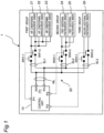
- Fig. 1 is a configuration diagram of an air conditioner 1 according to a first embodiment of the present disclosure.
- the air conditioner 1 includes: a control unit 10 configured to control an air conditioning operation; a serial communication bus 20 including a main communication line ML having a first end connected to the control unit 10 and first to third sub communication lines SL1 to SL3 branched off from a second end of the main communication line ML; air conditioning operation-specific sensors 21 to 23 (devices) connected to the first sub communication line SL1; first additional function-specific sensors 24 and 25 (devices) connected to the second sub communication line SL2; a second additional function-specific sensor 26 (a device) connected to the third sub communication line SL3; switches SW1-1 and SW1-2 disposed on the first sub communication line SL1 and configured to connect and disconnect the air conditioning operation-specific sensors 21 to 23 to and from the control unit 10; switches SW2-1 and SW2-2 disposed on the second sub communication line SL2 and configured to connect and disconnect the first additional function-specific sensors 24 and 25 to and from the control unit 10; and switches SW3-1 and SW3-2
- the number of devices connected to each of the first to third sub communication lines SL1 to SL3 is one or more.
- the switches SW1-1 and SW1-2 serve as a first switching unit.
- the switches SW2-1 and SW2-2 serve as a second switching unit.
- the switches SW3-1 and SW3-2 serve as a third switching unit.
- the first to third sub communication lines SL1 to SL3 are respectively provided with the first to third switching units (SW1-1, SW1-2; SW2-1, SW2-2; SW3-1, SW3-2).
- the control unit 10 the serial communication bus 20, the air conditioning operation-specific sensors 21 to 23 (devices), the first additional function-specific sensors 24 and 25 (devices), the second additional function-specific sensor 26 (a device), the switches SW1-1 and SW1-2, the switches SW2-1 and SW2-2, and the switches SW3-1 and SW3-2 constitute an environment control system.
- Examples of the devices connected to the first to third sub communication lines SL1 to SL3 may include, but not limited to, a sensor for detecting physical information, an actuator, and a device intended for environment control.
- the control unit 10 includes a microcomputer, an input and output circuit, and the like.
- the control unit 10 has an SDA terminal to which a serial data line of the serial communication bus 20 is connected, and an SCL terminal to which a serial clock line of the serial communication bus 20 is connected.
- the control unit 10 also has an output terminal P1 from which a control signal is output for turning on or off the switches SW1-1 and SW1-2, an output terminal P2 from which a control signal is output for turning on or off the switches SW2-1 and SW2-2, and an output terminal P3 from which a control signal is output for turning on or off the switches SW3-1 and SW3-2.
- the control unit 10 communicates with the air conditioning operation-specific sensors 21 to 23, the first additional function-specific sensors 24 and 25, and the second additional function-specific sensor 26 via the serial communication bus 20, using the I 2 C (Inter-Integrated Circuit) protocol. It should be noted that any serial communication protocol may be employed in addition to the I 2 C protocol.
- the air conditioning operation-specific sensors 21 to 23 belong to a first group
- the first additional function-specific sensors 24 and 25 belong to a second group
- the second additional function-specific sensor 26 belongs to a third group.
- the air conditioning operation-specific sensors 21 to 23 in the first group may include, but not limited to, a temperature sensor, a humidity sensor, a floor-temperature sensor, and a wall-temperature sensor.
- the first additional function-specific sensors 24 and 25 in the second group may include, but not limited to, a temperature sensor for detecting a temperature inside a humidifying duct in a case where the air conditioner 1 includes a humidifying unit, a humidity sensor for detecting a humidity inside the humidifying duct in the same case, and a voice processing device.
- the second additional function-specific sensor 26 in the third group may include, but not limited to, a CO 2 sensor for use in control of a ventilating operation as a new additional function.
- the control unit 10 performs processing for, for example, a cooling operation or a heating operation, based on signals from the air conditioning operation-specific sensors 21 to 23.
- the control unit 10 turns on all the switches SW1-1, SW1-2, SW2-1, SW2-2, SW3-1, and SW3-2, so that the air conditioning operation-specific sensors 21 to 23, the first additional function-specific sensors 24 and 25, and the second additional function-specific sensor 26 are connected to the control unit 10 via the serial communication bus 20.
- step S1 when the abnormal communication determination processing starts, in step S1, the control unit 10 starts to communicate with the air conditioning operation-specific sensors 21 to 23, the first additional function-specific sensors 24 and 25, and the second additional function-specific sensor 26.
- step S2 the control unit 10 determines whether the communications are abnormal. When the communications are abnormal, the processing proceeds to step S3. When the communications are not abnormal, i.e., are normal, the processing ends.
- step S3 the control unit 10 turns off the switches SW1-1 and SW1-2 (the switches SW2-1, SW2-2, SW3-1, and SW3-2 remain in an on state). Only the air conditioning operation-specific sensors 21 to 23 in the first group are thus disconnected from the control unit 10.
- step S4 when the control unit 10 determines that it has recovered from abnormal communications, the processing proceeds to step S5.
- step S4 when the control unit 10 determines that it has not recovered from the abnormal communications, the processing proceeds to step S6.
- step S5 the control unit 10 determines that the first group is abnormal. The processing then ends. In this case, a malfunction occurs at at least one of the air conditioning operation-specific sensors 21 to 23 in the first group.
- step S6 the control unit 10 turns on the switches SW1-1 and SW1-2, and turns off the switches SW2-1 and SW2-2 (the switches SW3-1 and SW3-2 remain in an on state). Only the first additional function-specific sensors 24 and 25 in the second group are thus disconnected from the control unit 10.
- step S7 when the control unit 10 determines that it has recovered from abnormal communications, the processing proceeds to step S8.
- step S7 when the control unit 10 determines that it has not recovered from the abnormal communications, the processing proceeds to step S9.
- step S8 the control unit 10 determines that the second group is abnormal. The processing then ends. In this case, a malfunction occurs at at least one of the first additional function-specific sensors 24 and 25 in the second group.
- step S9 the control unit 10 turns on the switches SW2-1 and SW2-2, and turns off the switches SW3-1 and SW3-2 (the switches SW1-1 and SW1-2 remain in an on state). Only the second additional function-specific sensor 26 in the third group is thus disconnected from the control unit 10.
- step S10 when the control unit 10 determines that it has recovered from abnormal communications, the processing proceeds to step S11.
- step S11 the control unit 10 determines that the third group is abnormal. The processing then ends. In this case, a malfunction occurs at the second additional function-specific sensor 26 in the third group.
- step S10 when the control unit 10 determines that it has not recovered from the abnormal communications, the processing proceeds to step S12.
- step S12 the control unit 10 determines that the serial communication bus 20 is abnormal. The processing then ends.
- the control unit 10 determines that the serial communication bus 20 is abnormal, because of, for example, a malfunction at a communication circuit of the control unit 10 and a malfunction, such as a break or a short circuit, of the serial communication bus 20 itself.
- Fig. 3 is a configuration diagram of an air conditioner according to a comparative example.
- the comparative example is merely illustrative for understanding the present invention with ease, and is not intended to limit the present invention.
- an air conditioner 101 includes: a control unit 110 configured to control an air conditioning operation; a serial communication bus 120 including a main communication line ML having a first end connected to the control unit 110 and a plurality of sub communication lines SL1 to SL6 branched off from a second end of the main communication line ML; an air conditioning operation-specific sensor 21 connected to the sub communication line SL1; an air conditioning operation-specific sensor 22 connected to the sub communication line SL2; an air conditioning operation-specific sensor 23 connected to the sub communication line SL3; a first additional function-specific sensor 24 connected to the sub communication line SL4; a first additional function-specific sensor 25 connected to the sub communication line SL5; and a second additional function-specific sensor 26 connected to the sub communication line SL6.
- the control unit 110 includes a microcomputer, an input and output circuit, and the like.
- the control unit 110 has an SDA terminal to which a serial data line of the serial communication bus 120 is connected, and an SCL terminal to which a serial clock line of the serial communication bus 120 is connected.
- the control unit 110 communicates with the air conditioning operation-specific sensors 21 to 23, the first additional function-specific sensors 24 and 25, and the second additional function-specific sensor 26 via the serial communication bus 120, using the I 2 C (Inter-Integrated Circuit) protocol.
- I 2 C Inter-Integrated Circuit
- the air conditioner 101 according to the comparative example if one sensor among the air conditioning operation-specific sensors 21 to 23, the first additional function-specific sensors 24 and 25, and the second additional function-specific sensor 26 malfunctions to fail to establish communications via the serial communication bus 120, the remaining normal sensors fall into communication failures. As a result, the control unit 110 is incapable of controlling the air conditioner 101. Consequently, the air conditioner 101 according to the comparative example fails to continue the air conditioning operation.
- the communication failures of the air conditioning operation-specific sensors 21 to 23, the first additional function-specific sensors 24 and 25, and the second additional function-specific sensor 26 may occur because at least one of the serial data line or the serial clock line of the serial communication bus 120 is placed in a short circuit mode.
- the air conditioner 1 identifies a failed sensor among the air conditioning operation-specific sensors 21 to 23, the first additional function-specific sensors 24 and 25, and the second additional function-specific sensor 26 connected to the control unit 10 via the serial communication bus 20, and makes the remaining normal sensors usable.
- the control unit 10 identifies the failed device by opening the first switching unit (the switches SW1-1 and SW1-2), the second switching unit (the switches SW2-1 and SW2-2), and the third switching unit (the switches SW3-1 and SW3-2) respectively disposed on the first to third sub communication lines SL1 to SL3, in sequence.
- control unit 10 fails to communicate with all the devices because of a malfunction at the first additional function-specific sensor 24, the control unit 10 opens the switches SW2-1 and SW2-2 on the second sub communication line SL2 to which the failed first additional function-specific sensor 24 is connected, thereby disconnecting the failed first additional function-specific sensor 24 and the first additional function-specific sensor 25 therefrom.
- the control unit 10 thus recovers the communications with the normal air conditioning operation-specific sensors 21 to 23 and the communication with the normal second additional function-specific sensor 26.
- disconnecting the failed device from the control unit 10 makes the normal devices continuously usable.
- control unit 10 If the control unit 10 abnormally communicates with all the devices, the control units 10 opens and closes the first switching unit (the switches SW1-1 and SW1-2), the second switching unit (the switches SW2-1 and SW2-2), and the third switching unit (the switches SW3-1 and SW3-2) to determine which device malfunctions to cause abnormal communication. The control unit 10 thus identifies the failed device, and disconnects the failed device therefrom.
- the control unit 10 determines whether the communications are abnormal, by opening first the switches SW1-1 and SW1-2 for the devices (the air conditioning operation-specific sensors 21 to 23) that enable continuation of the environment controlling operation, among the switches SW1-1 and SW1-2, the switches SW2-1 and SW2-2, and the switches SW3-1 and SW3-2.
- the air conditioner 1 continues the air conditioning operation using the devices (the air conditioning operation-specific sensors 21 to 23).
- the control unit 10 If the control unit 10 abnormally communicates with all the devices, the control unit 10 opens the first switching unit (the switches SW1-1 and SW1-2), the second switching unit (the switches SW2-1 and SW2-2), and the third switching unit (the switches SW3-1 and SW3-2) respectively disposed on the first to third sub communication lines SL1 to SL3, one by one in sequence.
- the control unit 10 normally communicates with the devices connected to two of the sub communication lines SL1 to SL3 on which the closed switching units are disposed, then the control unit 10 determines that a malfunction or failure occurs at the device connected to the sub communication line on which the opened switching unit is disposed. With this configuration, the control unit 10 accurately identifies a failed one of the devices connected to the first to third sub communication lines SL1 to SL3.
- the air conditioner 1 thus embodied is capable of identifying a failed one of the devices connected to the control unit 10 via the serial communication bus 20, and disconnecting the failed device from the control unit 10, thereby making the remaining normal devices usable.
- the first embodiment concerns the air conditioner 1 including the environment control system.
- the present disclosure may be applied to an air conditioning system including external devices, such as a sensor and an actuator, connected to the air conditioner 1 via a serial communication bus.
- the number of devices connected to each of the first sub communication line SL1 and the second sub communication line SL2 is two or more.
- the number of devices connected to each of the first to third sub communication lines SL1 to SL3 may be one.
- the environment control system includes the first to third sub communication lines SL1 to SL3.
- the number of sub communication lines is not limited to three.
- the present invention may be applied to an environment control system including first to Nth (N: an integer of 2 or more) sub communication lines SL1 to SL3.
- Fig. 4 is a configuration diagram of an air conditioner 1 according to a second embodiment of the present disclosure.
- the air conditioner 1 according to the second embodiment is identical in configuration to the air conditioner 1 according to the first embodiment except that the air conditioner 1 according to the second embodiment does not include the switches SW1-1 and SW1-2 described in the first embodiment, and a control unit 10 in the second embodiment is different in operation from that in the first embodiment.
- the control unit 10 a serial communication bus 20, air conditioning operation-specific sensors 21 to 23 (devices), first additional function-specific sensors 24 and 25 (devices), a second additional function-specific sensor 26 (a device), switches SW2-1 and SW2-2, and switches SW3-1 and SW3-2 constitute an environment control system.
- the control unit 10 performs processing for, for example, a cooling operation or a heating operation, based on signals from the air conditioning operation-specific sensors 21 to 23.
- the control unit 10 turns on all the switches SW2-1, SW2-2, SW3-1, and SW3-2, so that the air conditioning operation-specific sensors 21 to 23, the first additional function-specific sensors 24 and 25, and the second additional function-specific sensor 26 are connected to the control unit 10 via the serial communication bus 20.
- step S21 when the abnormal communication determination processing starts, in step S21, the control unit 10 starts to communicate with the air conditioning operation-specific sensors 21 to 23, the first additional function-specific sensors 24 and 25, and the second additional function-specific sensor 26.
- step S22 the control unit 10 determines whether the communications are abnormal. When the communications are abnormal, the processing proceeds to step S23. When the communications are normal, the processing ends.
- step S23 the control unit 10 turns off the switches SW2-1, SW2-2, SW3-1, and SW3-2. Only the air conditioning operation-specific sensors 21 to 23 in a first group are thus connected to the control unit 10.
- step S24 when the control unit 10 determines that the communications are abnormal, the processing proceeds to step S25.
- step S24 when the control unit 10 determines that the communications are normal, the processing proceeds to step S26.
- step S25 the control unit 10 determines that the first group is abnormal. The processing then ends. In this case, a malfunction may occur at at least one of the air conditioning operation-specific sensors 21 to 23 in the first group.
- step S26 the control unit 10 turns on the switches SW2-1 and SW2-2, and turns off the switches SW3-1 and SW3-2.
- the air conditioning operation-specific sensors 21 to 23 in the first group, which normally communicate with the control unit 10, and the first additional function-specific sensors 24 and 25 in a second group are thus connected to the control unit 10.
- step S27 when the control unit 10 determines that the communications are abnormal, the processing proceeds to step S28.
- step S27 when the control unit 10 determines that the communications are normal, the processing proceeds to step S29.
- step S28 the control unit 10 determines that the second group is abnormal. The processing then ends. In this case, a malfunction may occur at at least one of the first additional function-specific sensors 24 and 25 in the second group.
- step S29 the control unit 10 turns off the switches SW2-1 and SW2-2, and turns on the switches SW3-1 and SW3-2.
- the air conditioning operation-specific sensors 21 to 23 in the first group, which normally communicate with the control unit 10, and the second additional function-specific sensor 26 in a third group are thus connected to the control unit 10.
- step S30 when the control unit 10 determines the communications are abnormal, the processing proceeds to step S31.
- step S31 the control unit 10 determines that the third group is abnormal. The processing then ends. In this case, a malfunction may occur at the second additional function-specific sensor 26 in the third group.
- step S30 when the control unit 10 determines that the communications are normal, the processing proceeds to step S32.
- step S32 the control unit 10 determines that the serial communication bus 20 is abnormal. The processing then ends.
- the serial communication bus 20 may become abnormal, because of, for example, a malfunction at a communication circuit of the control unit 10 and a malfunction, such as a break or a short circuit, of the serial communication bus 20 itself.
- the air conditioner 1 according to the second embodiment is capable of identifying a failed one of the devices connected to the control unit via the serial communication bus, and making the remaining normal devices usable.
- a third embodiment of the present disclosure is directed to an underfloor heating system.
- the underfloor heating system may employ hot water as a heat source or may employ an electric heater as a heat source.
- the underfloor heating system according to the third embodiment includes an environment control system similar in configuration to the environment control system according to the first embodiment except the air conditioning operation-specific sensors 21 to 23 (the devices), the first additional function-specific sensors 24 and 25 (the devices), and the second additional function-specific sensor 26 (the device).
- the underfloor heating system includes a plurality of devices such as an underfloor heating-specific sensor and an indoor temperature sensor.
- the underfloor heating system having the configuration described above is capable of identifying a failed one of the devices connected to a control unit via a serial communication bus, and making the remaining normal devices usable.
- a fourth embodiment of the present disclosure is directed to a hot-water heating system.
- the hot-water heating system according to the fourth embodiment includes an environment control system similar in configuration to the environment control system according to the first embodiment except the air conditioning operation-specific sensors 21 to 23 (the devices), the first additional function-specific sensors 24 and 25 (the devices), and the second additional function-specific sensor 26 (the device).
- the hot-water heating system includes a plurality of devices such as a hot-water heating-specific sensor.
- the hot-water heating system having the configuration described above is capable of identifying a failed one of the devices connected to a control unit via a serial communication bus, and making the remaining normal devices usable.
- the first to fourth embodiments describe the air conditioner 1, underfloor heating system, and hot-water heating system each including the environment control system.
- an environment control system is not limited thereto.
- the present invention may be applied to another system for controlling an environment.
Landscapes
- Engineering & Computer Science (AREA)
- General Engineering & Computer Science (AREA)
- Combustion & Propulsion (AREA)
- Mechanical Engineering (AREA)
- Chemical & Material Sciences (AREA)
- Theoretical Computer Science (AREA)
- Physics & Mathematics (AREA)
- Signal Processing (AREA)
- Biomedical Technology (AREA)
- Human Computer Interaction (AREA)
- Health & Medical Sciences (AREA)
- Quality & Reliability (AREA)
- General Physics & Mathematics (AREA)
- Mathematical Physics (AREA)
- Fuzzy Systems (AREA)
- Air Conditioning Control Device (AREA)
- Selective Calling Equipment (AREA)
Claims (4)
- Umweltregelungssystem, umfassend:eine Steuerungseinheit (10);einen seriellen Kommunikationsbus (20), der einschließteine Hauptkommunikationsleitung (ML) mit einem ersten Ende, das mit der Steuereinheit (10) verbunden ist, underste bis N-te (N: eine ganze Zahl von 2 oder mehr) Unterkommunikationsleitungen (SL1 bis SL3), die von einem zweiten Ende der Hauptkommunikationsleitung (ML) abzweigen;Vorrichtungen (21 bis 26), die mit den ersten bis N-ten Unterkommunikationsleitungen (SL1 bis SL3) verbunden sind; undSchalteinheiten (SW2-1, SW2-2, SW3-1, SW3-2), die an den Unterkommunikationsleitungen (SL2, SL3) mit Ausnahme der ersten Unterkommunikationsleitung (SL1) angeordnet und so konfiguriert sind, dass sie die Vorrichtungen (24 bis 26) mit der Steuereinheit (10) verbinden und von ihr trennen,wobei jede der ersten bis N-ten Unterkommunikationsleitungen (SL1 bis SL3) mit einer oder mehreren der Vorrichtungen (24-26) verbunden ist, wobeiwenn die Steuereinheit (10) abnormal mit den Vorrichtungen (21 bis 26) kommuniziert, die Steuereinheit (10) die Schalteinheiten (SW2-1, SW2-2, SW3-1, SW3-2) öffnet und, wenn die Steuereinheit (10) abnormal mit einer Vorrichtung oder Vorrichtungen (21 bis 23) kommuniziert, die mit der ersten Unterkommunikationsleitung (SL1) verbunden sind, bestimmt, dass eine Fehlfunktion bei der Vorrichtung oder den Vorrichtungen (21 bis 23) auftritt, die mit der ersten Unterkommunikationsleitung (SL1) verbunden sind, undwenn die Steuereinheit (10) abnormal mit den Vorrichtungen (21 bis 26) kommuniziert, die Steuereinheit (10) die Schalteinheiten (SW2-1, SW2-2, SW3-1, SW3-2) öffnet, und wenn die Steuereinheit (10) normal mit der Vorrichtung oder den Vorrichtungen (21 bis 23) kommuniziert, die mit der ersten Unterkommunikationsleitung (SL1) verbunden sind, die Steuereinheit (1) die Schalteinheiten eine nach der anderen nacheinander schließt, und wenn die Steuereinheit (1) abnormal mit einer Vorrichtung oder Vorrichtungen kommuniziert, die mit einer Unterkommunikationsleitung (SL2, SL3) verbunden sind, für die die Schalteinheit geschlossen ist, die Steuereinheit bestimmt, dass eine Fehlfunktion bei der Vorrichtung oder den Vorrichtungen (24 bis 26) auftritt.
- Umweltregelungssystem nach Anspruch 1, wobei die Steuereinheit (10) Ausgangsanschlüsse einschließt, von denen jeweils ein Steuersignal an die jeweiligen Schalteinheiten (SW2-1, SW2-2, SW3-1, SW3-2) ausgegeben wird, um die jeweiligen Schalteinheiten (SW2-1, SW2-2, SW3-1, SW3-2) zu schließen oder zu öffnen.
- Umweltregelungssystem nach Anspruch 1 oder 2, wobei, wenn die Steuereinheit (10) die Schalteinheiten (SW2-1, SW2-2, SW3-1, SW3-2) eine nach der anderen nacheinander schließt und normal mit den mit den Unterkommunikationsleitungen (SL2, SL3) verbundenen Vorrichtungen mit Ausnahme der ersten Unterkommunikationsleitungen (SL1) kommuniziert, die Steuereinheit (10) bestimmt, dass der serielle Kommunikations-(20) Bus abnormal ist.
- Klimaanlage oder Klimatisierungssystem, umfassend:
das Umweltregelungssystem nach einem der Ansprüche 1 bis 3.
Applications Claiming Priority (2)
| Application Number | Priority Date | Filing Date | Title |
|---|---|---|---|
| JP2019006721 | 2019-01-18 | ||
| PCT/JP2019/051573 WO2020149153A1 (ja) | 2019-01-18 | 2019-12-27 | 環境制御システム、空気調和機または空気調和システム |
Publications (3)
| Publication Number | Publication Date |
|---|---|
| EP3819769A1 EP3819769A1 (de) | 2021-05-12 |
| EP3819769A4 EP3819769A4 (de) | 2021-09-29 |
| EP3819769B1 true EP3819769B1 (de) | 2023-11-01 |
Family
ID=71613784
Family Applications (1)
| Application Number | Title | Priority Date | Filing Date |
|---|---|---|---|
| EP19910476.1A Active EP3819769B1 (de) | 2019-01-18 | 2019-12-27 | Klimaregelungssystem und klimaanlage oder klimatisierungssystem |
Country Status (7)
| Country | Link |
|---|---|
| US (1) | US11619412B2 (de) |
| EP (1) | EP3819769B1 (de) |
| JP (1) | JP7018049B2 (de) |
| CN (1) | CN112585587A (de) |
| AU (1) | AU2019423037B2 (de) |
| ES (1) | ES2966535T3 (de) |
| WO (1) | WO2020149153A1 (de) |
Families Citing this family (1)
| Publication number | Priority date | Publication date | Assignee | Title |
|---|---|---|---|---|
| JP7456925B2 (ja) * | 2020-12-24 | 2024-03-27 | ダイキン工業株式会社 | 空気処理装置 |
Family Cites Families (21)
| Publication number | Priority date | Publication date | Assignee | Title |
|---|---|---|---|---|
| JPH0738967A (ja) * | 1993-07-21 | 1995-02-07 | Mitsubishi Electric Corp | 機器管理システムおよび機器管理システムの機器接続設定方法 |
| US6459370B1 (en) * | 1998-11-03 | 2002-10-01 | Adt Services Ag | Method and apparatus for determining proper installation of alarm devices |
| JP2001005743A (ja) * | 1999-06-17 | 2001-01-12 | Toyo Commun Equip Co Ltd | 伝送装置 |
| JP2002108637A (ja) | 2000-10-03 | 2002-04-12 | Funai Electric Co Ltd | 電子機器の設定方法 |
| JP4169489B2 (ja) * | 2001-04-25 | 2008-10-22 | 三洋電機株式会社 | 空気調和システム |
| US6889345B2 (en) * | 2001-10-19 | 2005-05-03 | Hewlett-Packard Development Company, Lp. | System and method for locating a failed storage device in a data storage system |
| US7775452B2 (en) * | 2004-01-07 | 2010-08-17 | Carrier Corporation | Serial communicating HVAC system |
| JP2008039344A (ja) | 2006-08-10 | 2008-02-21 | Sanyo Electric Co Ltd | 空気調和システム |
| JP2008278403A (ja) | 2007-05-07 | 2008-11-13 | Fujitsu Ten Ltd | 監視装置及びネットワークシステムの監視方法 |
| US8452906B2 (en) * | 2008-10-27 | 2013-05-28 | Lennox Industries, Inc. | Communication protocol system and method for a distributed-architecture heating, ventilation and air conditioning network |
| TW201201023A (en) * | 2010-06-30 | 2012-01-01 | Hon Hai Prec Ind Co Ltd | Inter-Integrated Circuit device communication circuit |
| US10075533B2 (en) * | 2011-09-15 | 2018-09-11 | Paypal, Inc. | Method and apparatus for transferring the state of content using short codes |
| US8935450B2 (en) * | 2011-09-16 | 2015-01-13 | Nxp B.V. | Network communications circuit, system and method |
| KR20140107002A (ko) * | 2013-02-27 | 2014-09-04 | 엘지전자 주식회사 | 공기 조화기 및 그 제어방법 |
| US9946675B2 (en) * | 2013-03-13 | 2018-04-17 | Atieva, Inc. | Fault-tolerant loop for a communication bus |
| KR101572940B1 (ko) * | 2014-12-08 | 2015-11-30 | 현대자동차주식회사 | 게이트웨이를 이용한 통신 장애 복구 방법 및 시스템 |
| US10798544B2 (en) * | 2015-05-29 | 2020-10-06 | Huawei Technologies Co., Ltd. | Method for exchanging data with in-vehicle infotainment, server, mobile terminal, and apparatus |
| US10536033B2 (en) * | 2016-03-23 | 2020-01-14 | Novanta Corporation | System and method of bi-directional communication for position sensors involving superposition of data over low voltage DC power using two conductors |
| EP3484004A1 (de) * | 2017-11-08 | 2019-05-15 | Electricity North West Property Limited | Steuerungssystem und verfahren zur fehlerlokalisierung, isolierung und versorgungswiederherstellung |
| CN108073540B (zh) * | 2018-02-11 | 2024-10-18 | 云丁网络技术(北京)有限公司 | I2c总线系统、异常设备排查方法 |
| CN208126373U (zh) * | 2018-05-07 | 2018-11-20 | 广州视源电子科技股份有限公司 | 一种iic故障的检测响应电路和iic总线系统 |
-
2019
- 2019-12-25 JP JP2019234197A patent/JP7018049B2/ja active Active
- 2019-12-27 AU AU2019423037A patent/AU2019423037B2/en active Active
- 2019-12-27 ES ES19910476T patent/ES2966535T3/es active Active
- 2019-12-27 WO PCT/JP2019/051573 patent/WO2020149153A1/ja not_active Ceased
- 2019-12-27 CN CN201980055047.9A patent/CN112585587A/zh active Pending
- 2019-12-27 EP EP19910476.1A patent/EP3819769B1/de active Active
- 2019-12-27 US US17/266,512 patent/US11619412B2/en active Active
Also Published As
| Publication number | Publication date |
|---|---|
| EP3819769A1 (de) | 2021-05-12 |
| CN112585587A (zh) | 2021-03-30 |
| JP7018049B2 (ja) | 2022-02-09 |
| AU2019423037B2 (en) | 2022-03-10 |
| ES2966535T3 (es) | 2024-04-22 |
| US20210310682A1 (en) | 2021-10-07 |
| WO2020149153A1 (ja) | 2020-07-23 |
| AU2019423037A1 (en) | 2021-03-04 |
| EP3819769A4 (de) | 2021-09-29 |
| US11619412B2 (en) | 2023-04-04 |
| JP2020118438A (ja) | 2020-08-06 |
Similar Documents
| Publication | Publication Date | Title |
|---|---|---|
| US8352080B2 (en) | Communication protocol system and method for a distributed-architecture heating, ventilation and air conditioning network | |
| US5853123A (en) | Signal transmission/reception device of air conditioner | |
| US8560125B2 (en) | Communication protocol system and method for a distributed-architecture heating, ventilation and air conditioning network | |
| US7495356B2 (en) | Dual power supply system | |
| US8352081B2 (en) | Communication protocol system and method for a distributed-architecture heating, ventilation and air conditioning network | |
| US8452906B2 (en) | Communication protocol system and method for a distributed-architecture heating, ventilation and air conditioning network | |
| CN110967641B (zh) | 蓄电池监控系统及方法 | |
| US6728601B2 (en) | Multiple host power control system and method | |
| AU2019423037B2 (en) | Environment control system and air conditioner or air-conditioning system | |
| KR101234827B1 (ko) | 공기조화기의 통신이상 진단시스템 및 그 방법 | |
| US7562253B1 (en) | Segmented protection system and method | |
| EP3222926B1 (de) | Klimaanlage | |
| CN117459368B (zh) | 用于储能系统的控制方法 | |
| JP3018929B2 (ja) | 空気調和装置の伝送装置 | |
| CN211043555U (zh) | 简化结构的故障检测电路及空调设备 | |
| JP6976235B2 (ja) | 系切替制御システム | |
| CN108693861A (zh) | 热备中继器、双机热备份系统及控制切换方法 | |
| US11954054B2 (en) | Communication system, slave unit used for communication system, and communication method | |
| EP4354804B1 (de) | Netzwerkschnittstelle mit deaktivierbarer automatischer bypass-funktionalität zwischen zwei netzwerkverbindern | |
| JP3435276B2 (ja) | 装置状態通知方法 | |
| US20260135730A1 (en) | Network interface with deactivatable automatic bypass functionality between two network connectors | |
| CN218387528U (zh) | 负载模块、通信系统及家电设备 | |
| WO2024201652A1 (ja) | 空調システム | |
| JP4096849B2 (ja) | 回線多重化構造を用いた入出力制御システム | |
| CN120972848A (zh) | 一种状态监测装置、车载控制系统及车辆 |
Legal Events
| Date | Code | Title | Description |
|---|---|---|---|
| STAA | Information on the status of an ep patent application or granted ep patent |
Free format text: STATUS: THE INTERNATIONAL PUBLICATION HAS BEEN MADE |
|
| PUAI | Public reference made under article 153(3) epc to a published international application that has entered the european phase |
Free format text: ORIGINAL CODE: 0009012 |
|
| STAA | Information on the status of an ep patent application or granted ep patent |
Free format text: STATUS: REQUEST FOR EXAMINATION WAS MADE |
|
| 17P | Request for examination filed |
Effective date: 20210203 |
|
| AK | Designated contracting states |
Kind code of ref document: A1 Designated state(s): AL AT BE BG CH CY CZ DE DK EE ES FI FR GB GR HR HU IE IS IT LI LT LU LV MC MK MT NL NO PL PT RO RS SE SI SK SM TR |
|
| A4 | Supplementary search report drawn up and despatched |
Effective date: 20210901 |
|
| RIC1 | Information provided on ipc code assigned before grant |
Ipc: F24F 11/63 20180101ALI20210826BHEP Ipc: F24F 11/54 20180101ALI20210826BHEP Ipc: F24F 11/50 20180101ALI20210826BHEP Ipc: G06F 11/07 20060101ALI20210826BHEP Ipc: F24F 11/88 20180101ALI20210826BHEP Ipc: F24F 11/38 20180101ALI20210826BHEP Ipc: G06F 11/22 20060101AFI20210826BHEP |
|
| DAV | Request for validation of the european patent (deleted) | ||
| DAX | Request for extension of the european patent (deleted) | ||
| STAA | Information on the status of an ep patent application or granted ep patent |
Free format text: STATUS: EXAMINATION IS IN PROGRESS |
|
| 17Q | First examination report despatched |
Effective date: 20220609 |
|
| RAP3 | Party data changed (applicant data changed or rights of an application transferred) |
Owner name: DAIKIN INDUSTRIES, LTD. |
|
| GRAP | Despatch of communication of intention to grant a patent |
Free format text: ORIGINAL CODE: EPIDOSNIGR1 |
|
| STAA | Information on the status of an ep patent application or granted ep patent |
Free format text: STATUS: GRANT OF PATENT IS INTENDED |
|
| INTG | Intention to grant announced |
Effective date: 20230523 |
|
| P01 | Opt-out of the competence of the unified patent court (upc) registered |
Effective date: 20230525 |
|
| GRAS | Grant fee paid |
Free format text: ORIGINAL CODE: EPIDOSNIGR3 |
|
| GRAA | (expected) grant |
Free format text: ORIGINAL CODE: 0009210 |
|
| STAA | Information on the status of an ep patent application or granted ep patent |
Free format text: STATUS: THE PATENT HAS BEEN GRANTED |
|
| AK | Designated contracting states |
Kind code of ref document: B1 Designated state(s): AL AT BE BG CH CY CZ DE DK EE ES FI FR GB GR HR HU IE IS IT LI LT LU LV MC MK MT NL NO PL PT RO RS SE SI SK SM TR |
|
| REG | Reference to a national code |
Ref country code: GB Ref legal event code: FG4D |
|
| REG | Reference to a national code |
Ref country code: CH Ref legal event code: EP |
|
| REG | Reference to a national code |
Ref country code: DE Ref legal event code: R096 Ref document number: 602019040856 Country of ref document: DE |
|
| REG | Reference to a national code |
Ref country code: IE Ref legal event code: FG4D |
|
| REG | Reference to a national code |
Ref country code: LT Ref legal event code: MG9D |
|
| REG | Reference to a national code |
Ref country code: NL Ref legal event code: MP Effective date: 20231101 |
|
| PG25 | Lapsed in a contracting state [announced via postgrant information from national office to epo] |
Ref country code: GR Free format text: LAPSE BECAUSE OF FAILURE TO SUBMIT A TRANSLATION OF THE DESCRIPTION OR TO PAY THE FEE WITHIN THE PRESCRIBED TIME-LIMIT Effective date: 20240202 |
|
| PG25 | Lapsed in a contracting state [announced via postgrant information from national office to epo] |
Ref country code: IS Free format text: LAPSE BECAUSE OF FAILURE TO SUBMIT A TRANSLATION OF THE DESCRIPTION OR TO PAY THE FEE WITHIN THE PRESCRIBED TIME-LIMIT Effective date: 20240301 |
|
| PG25 | Lapsed in a contracting state [announced via postgrant information from national office to epo] |
Ref country code: LT Free format text: LAPSE BECAUSE OF FAILURE TO SUBMIT A TRANSLATION OF THE DESCRIPTION OR TO PAY THE FEE WITHIN THE PRESCRIBED TIME-LIMIT Effective date: 20231101 |
|
| REG | Reference to a national code |
Ref country code: AT Ref legal event code: MK05 Ref document number: 1627999 Country of ref document: AT Kind code of ref document: T Effective date: 20231101 |
|
| PG25 | Lapsed in a contracting state [announced via postgrant information from national office to epo] |
Ref country code: NL Free format text: LAPSE BECAUSE OF FAILURE TO SUBMIT A TRANSLATION OF THE DESCRIPTION OR TO PAY THE FEE WITHIN THE PRESCRIBED TIME-LIMIT Effective date: 20231101 |
|
| REG | Reference to a national code |
Ref country code: ES Ref legal event code: FG2A Ref document number: 2966535 Country of ref document: ES Kind code of ref document: T3 Effective date: 20240422 |
|
| PG25 | Lapsed in a contracting state [announced via postgrant information from national office to epo] |
Ref country code: AT Free format text: LAPSE BECAUSE OF FAILURE TO SUBMIT A TRANSLATION OF THE DESCRIPTION OR TO PAY THE FEE WITHIN THE PRESCRIBED TIME-LIMIT Effective date: 20231101 |
|
| PG25 | Lapsed in a contracting state [announced via postgrant information from national office to epo] |
Ref country code: NL Free format text: LAPSE BECAUSE OF FAILURE TO SUBMIT A TRANSLATION OF THE DESCRIPTION OR TO PAY THE FEE WITHIN THE PRESCRIBED TIME-LIMIT Effective date: 20231101 Ref country code: LT Free format text: LAPSE BECAUSE OF FAILURE TO SUBMIT A TRANSLATION OF THE DESCRIPTION OR TO PAY THE FEE WITHIN THE PRESCRIBED TIME-LIMIT Effective date: 20231101 Ref country code: IS Free format text: LAPSE BECAUSE OF FAILURE TO SUBMIT A TRANSLATION OF THE DESCRIPTION OR TO PAY THE FEE WITHIN THE PRESCRIBED TIME-LIMIT Effective date: 20240301 Ref country code: GR Free format text: LAPSE BECAUSE OF FAILURE TO SUBMIT A TRANSLATION OF THE DESCRIPTION OR TO PAY THE FEE WITHIN THE PRESCRIBED TIME-LIMIT Effective date: 20240202 Ref country code: BG Free format text: LAPSE BECAUSE OF FAILURE TO SUBMIT A TRANSLATION OF THE DESCRIPTION OR TO PAY THE FEE WITHIN THE PRESCRIBED TIME-LIMIT Effective date: 20240201 Ref country code: AT Free format text: LAPSE BECAUSE OF FAILURE TO SUBMIT A TRANSLATION OF THE DESCRIPTION OR TO PAY THE FEE WITHIN THE PRESCRIBED TIME-LIMIT Effective date: 20231101 Ref country code: PT Free format text: LAPSE BECAUSE OF FAILURE TO SUBMIT A TRANSLATION OF THE DESCRIPTION OR TO PAY THE FEE WITHIN THE PRESCRIBED TIME-LIMIT Effective date: 20240301 |
|
| PG25 | Lapsed in a contracting state [announced via postgrant information from national office to epo] |
Ref country code: SE Free format text: LAPSE BECAUSE OF FAILURE TO SUBMIT A TRANSLATION OF THE DESCRIPTION OR TO PAY THE FEE WITHIN THE PRESCRIBED TIME-LIMIT Effective date: 20231101 Ref country code: RS Free format text: LAPSE BECAUSE OF FAILURE TO SUBMIT A TRANSLATION OF THE DESCRIPTION OR TO PAY THE FEE WITHIN THE PRESCRIBED TIME-LIMIT Effective date: 20231101 Ref country code: PL Free format text: LAPSE BECAUSE OF FAILURE TO SUBMIT A TRANSLATION OF THE DESCRIPTION OR TO PAY THE FEE WITHIN THE PRESCRIBED TIME-LIMIT Effective date: 20231101 Ref country code: NO Free format text: LAPSE BECAUSE OF FAILURE TO SUBMIT A TRANSLATION OF THE DESCRIPTION OR TO PAY THE FEE WITHIN THE PRESCRIBED TIME-LIMIT Effective date: 20240201 Ref country code: LV Free format text: LAPSE BECAUSE OF FAILURE TO SUBMIT A TRANSLATION OF THE DESCRIPTION OR TO PAY THE FEE WITHIN THE PRESCRIBED TIME-LIMIT Effective date: 20231101 Ref country code: HR Free format text: LAPSE BECAUSE OF FAILURE TO SUBMIT A TRANSLATION OF THE DESCRIPTION OR TO PAY THE FEE WITHIN THE PRESCRIBED TIME-LIMIT Effective date: 20231101 |
|
| PG25 | Lapsed in a contracting state [announced via postgrant information from national office to epo] |
Ref country code: DK Free format text: LAPSE BECAUSE OF FAILURE TO SUBMIT A TRANSLATION OF THE DESCRIPTION OR TO PAY THE FEE WITHIN THE PRESCRIBED TIME-LIMIT Effective date: 20231101 |
|
| PG25 | Lapsed in a contracting state [announced via postgrant information from national office to epo] |
Ref country code: CZ Free format text: LAPSE BECAUSE OF FAILURE TO SUBMIT A TRANSLATION OF THE DESCRIPTION OR TO PAY THE FEE WITHIN THE PRESCRIBED TIME-LIMIT Effective date: 20231101 |
|
| PG25 | Lapsed in a contracting state [announced via postgrant information from national office to epo] |
Ref country code: SK Free format text: LAPSE BECAUSE OF FAILURE TO SUBMIT A TRANSLATION OF THE DESCRIPTION OR TO PAY THE FEE WITHIN THE PRESCRIBED TIME-LIMIT Effective date: 20231101 |
|
| PG25 | Lapsed in a contracting state [announced via postgrant information from national office to epo] |
Ref country code: SM Free format text: LAPSE BECAUSE OF FAILURE TO SUBMIT A TRANSLATION OF THE DESCRIPTION OR TO PAY THE FEE WITHIN THE PRESCRIBED TIME-LIMIT Effective date: 20231101 Ref country code: SK Free format text: LAPSE BECAUSE OF FAILURE TO SUBMIT A TRANSLATION OF THE DESCRIPTION OR TO PAY THE FEE WITHIN THE PRESCRIBED TIME-LIMIT Effective date: 20231101 Ref country code: EE Free format text: LAPSE BECAUSE OF FAILURE TO SUBMIT A TRANSLATION OF THE DESCRIPTION OR TO PAY THE FEE WITHIN THE PRESCRIBED TIME-LIMIT Effective date: 20231101 Ref country code: DK Free format text: LAPSE BECAUSE OF FAILURE TO SUBMIT A TRANSLATION OF THE DESCRIPTION OR TO PAY THE FEE WITHIN THE PRESCRIBED TIME-LIMIT Effective date: 20231101 Ref country code: CZ Free format text: LAPSE BECAUSE OF FAILURE TO SUBMIT A TRANSLATION OF THE DESCRIPTION OR TO PAY THE FEE WITHIN THE PRESCRIBED TIME-LIMIT Effective date: 20231101 |
|
| REG | Reference to a national code |
Ref country code: CH Ref legal event code: PL |
|
| REG | Reference to a national code |
Ref country code: DE Ref legal event code: R097 Ref document number: 602019040856 Country of ref document: DE |
|
| PG25 | Lapsed in a contracting state [announced via postgrant information from national office to epo] |
Ref country code: LU Free format text: LAPSE BECAUSE OF NON-PAYMENT OF DUE FEES Effective date: 20231227 |
|
| PG25 | Lapsed in a contracting state [announced via postgrant information from national office to epo] |
Ref country code: MC Free format text: LAPSE BECAUSE OF FAILURE TO SUBMIT A TRANSLATION OF THE DESCRIPTION OR TO PAY THE FEE WITHIN THE PRESCRIBED TIME-LIMIT Effective date: 20231101 |
|
| REG | Reference to a national code |
Ref country code: BE Ref legal event code: MM Effective date: 20231231 |
|
| PG25 | Lapsed in a contracting state [announced via postgrant information from national office to epo] |
Ref country code: MC Free format text: LAPSE BECAUSE OF FAILURE TO SUBMIT A TRANSLATION OF THE DESCRIPTION OR TO PAY THE FEE WITHIN THE PRESCRIBED TIME-LIMIT Effective date: 20231101 Ref country code: LU Free format text: LAPSE BECAUSE OF NON-PAYMENT OF DUE FEES Effective date: 20231227 |
|
| PLBE | No opposition filed within time limit |
Free format text: ORIGINAL CODE: 0009261 |
|
| STAA | Information on the status of an ep patent application or granted ep patent |
Free format text: STATUS: NO OPPOSITION FILED WITHIN TIME LIMIT |
|
| 26N | No opposition filed |
Effective date: 20240802 |
|
| REG | Reference to a national code |
Ref country code: IE Ref legal event code: MM4A |
|
| PG25 | Lapsed in a contracting state [announced via postgrant information from national office to epo] |
Ref country code: IE Free format text: LAPSE BECAUSE OF NON-PAYMENT OF DUE FEES Effective date: 20231227 |
|
| PG25 | Lapsed in a contracting state [announced via postgrant information from national office to epo] |
Ref country code: BE Free format text: LAPSE BECAUSE OF NON-PAYMENT OF DUE FEES Effective date: 20231231 |
|
| PG25 | Lapsed in a contracting state [announced via postgrant information from national office to epo] |
Ref country code: CH Free format text: LAPSE BECAUSE OF NON-PAYMENT OF DUE FEES Effective date: 20231231 |
|
| GBPC | Gb: european patent ceased through non-payment of renewal fee |
Effective date: 20240201 |
|
| PG25 | Lapsed in a contracting state [announced via postgrant information from national office to epo] |
Ref country code: SI Free format text: LAPSE BECAUSE OF FAILURE TO SUBMIT A TRANSLATION OF THE DESCRIPTION OR TO PAY THE FEE WITHIN THE PRESCRIBED TIME-LIMIT Effective date: 20231101 |
|
| PG25 | Lapsed in a contracting state [announced via postgrant information from national office to epo] |
Ref country code: SI Free format text: LAPSE BECAUSE OF FAILURE TO SUBMIT A TRANSLATION OF THE DESCRIPTION OR TO PAY THE FEE WITHIN THE PRESCRIBED TIME-LIMIT Effective date: 20231101 Ref country code: IE Free format text: LAPSE BECAUSE OF NON-PAYMENT OF DUE FEES Effective date: 20231227 Ref country code: CH Free format text: LAPSE BECAUSE OF NON-PAYMENT OF DUE FEES Effective date: 20231231 Ref country code: BE Free format text: LAPSE BECAUSE OF NON-PAYMENT OF DUE FEES Effective date: 20231231 |
|
| PG25 | Lapsed in a contracting state [announced via postgrant information from national office to epo] |
Ref country code: GB Free format text: LAPSE BECAUSE OF NON-PAYMENT OF DUE FEES Effective date: 20240201 |
|
| PG25 | Lapsed in a contracting state [announced via postgrant information from national office to epo] |
Ref country code: GB Free format text: LAPSE BECAUSE OF NON-PAYMENT OF DUE FEES Effective date: 20240201 |
|
| PG25 | Lapsed in a contracting state [announced via postgrant information from national office to epo] |
Ref country code: RO Free format text: LAPSE BECAUSE OF FAILURE TO SUBMIT A TRANSLATION OF THE DESCRIPTION OR TO PAY THE FEE WITHIN THE PRESCRIBED TIME-LIMIT Effective date: 20231101 |
|
| PG25 | Lapsed in a contracting state [announced via postgrant information from national office to epo] |
Ref country code: FI Free format text: LAPSE BECAUSE OF FAILURE TO SUBMIT A TRANSLATION OF THE DESCRIPTION OR TO PAY THE FEE WITHIN THE PRESCRIBED TIME-LIMIT Effective date: 20231101 |
|
| PG25 | Lapsed in a contracting state [announced via postgrant information from national office to epo] |
Ref country code: CY Free format text: LAPSE BECAUSE OF FAILURE TO SUBMIT A TRANSLATION OF THE DESCRIPTION OR TO PAY THE FEE WITHIN THE PRESCRIBED TIME-LIMIT; INVALID AB INITIO Effective date: 20191227 |
|
| PG25 | Lapsed in a contracting state [announced via postgrant information from national office to epo] |
Ref country code: HU Free format text: LAPSE BECAUSE OF FAILURE TO SUBMIT A TRANSLATION OF THE DESCRIPTION OR TO PAY THE FEE WITHIN THE PRESCRIBED TIME-LIMIT; INVALID AB INITIO Effective date: 20191227 |
|
| PG25 | Lapsed in a contracting state [announced via postgrant information from national office to epo] |
Ref country code: TR Free format text: LAPSE BECAUSE OF FAILURE TO SUBMIT A TRANSLATION OF THE DESCRIPTION OR TO PAY THE FEE WITHIN THE PRESCRIBED TIME-LIMIT Effective date: 20231101 |
|
| PGFP | Annual fee paid to national office [announced via postgrant information from national office to epo] |
Ref country code: DE Payment date: 20251211 Year of fee payment: 7 |
|
| PGFP | Annual fee paid to national office [announced via postgrant information from national office to epo] |
Ref country code: IT Payment date: 20251223 Year of fee payment: 7 |
|
| PGFP | Annual fee paid to national office [announced via postgrant information from national office to epo] |
Ref country code: FR Payment date: 20251229 Year of fee payment: 7 |
|
| PGFP | Annual fee paid to national office [announced via postgrant information from national office to epo] |
Ref country code: ES Payment date: 20260130 Year of fee payment: 7 |