EP3819525A1 - Zylinderdichtung - Google Patents
Zylinderdichtung Download PDFInfo
- Publication number
- EP3819525A1 EP3819525A1 EP20203268.6A EP20203268A EP3819525A1 EP 3819525 A1 EP3819525 A1 EP 3819525A1 EP 20203268 A EP20203268 A EP 20203268A EP 3819525 A1 EP3819525 A1 EP 3819525A1
- Authority
- EP
- European Patent Office
- Prior art keywords
- ring
- cylinder
- sealing
- piston rod
- section
- Prior art date
- Legal status (The legal status is an assumption and is not a legal conclusion. Google has not performed a legal analysis and makes no representation as to the accuracy of the status listed.)
- Granted
Links
Images




Classifications
-
- F—MECHANICAL ENGINEERING; LIGHTING; HEATING; WEAPONS; BLASTING
- F16—ENGINEERING ELEMENTS AND UNITS; GENERAL MEASURES FOR PRODUCING AND MAINTAINING EFFECTIVE FUNCTIONING OF MACHINES OR INSTALLATIONS; THERMAL INSULATION IN GENERAL
- F16J—PISTONS; CYLINDERS; SEALINGS
- F16J15/00—Sealings
- F16J15/16—Sealings between relatively-moving surfaces
- F16J15/32—Sealings between relatively-moving surfaces with elastic sealings, e.g. O-rings
- F16J15/3204—Sealings between relatively-moving surfaces with elastic sealings, e.g. O-rings with at least one lip
- F16J15/322—Sealings between relatively-moving surfaces with elastic sealings, e.g. O-rings with at least one lip supported in a direction perpendicular to the surfaces
-
- F—MECHANICAL ENGINEERING; LIGHTING; HEATING; WEAPONS; BLASTING
- F16—ENGINEERING ELEMENTS AND UNITS; GENERAL MEASURES FOR PRODUCING AND MAINTAINING EFFECTIVE FUNCTIONING OF MACHINES OR INSTALLATIONS; THERMAL INSULATION IN GENERAL
- F16J—PISTONS; CYLINDERS; SEALINGS
- F16J15/00—Sealings
- F16J15/16—Sealings between relatively-moving surfaces
- F16J15/32—Sealings between relatively-moving surfaces with elastic sealings, e.g. O-rings
- F16J15/3248—Sealings between relatively-moving surfaces with elastic sealings, e.g. O-rings provided with casings or supports
- F16J15/3252—Sealings between relatively-moving surfaces with elastic sealings, e.g. O-rings provided with casings or supports with rigid casings or supports
-
- B—PERFORMING OPERATIONS; TRANSPORTING
- B60—VEHICLES IN GENERAL
- B60G—VEHICLE SUSPENSION ARRANGEMENTS
- B60G13/00—Resilient suspensions characterised by arrangement, location or type of vibration dampers
- B60G13/02—Resilient suspensions characterised by arrangement, location or type of vibration dampers having dampers dissipating energy, e.g. frictionally
- B60G13/06—Resilient suspensions characterised by arrangement, location or type of vibration dampers having dampers dissipating energy, e.g. frictionally of fluid type
- B60G13/08—Resilient suspensions characterised by arrangement, location or type of vibration dampers having dampers dissipating energy, e.g. frictionally of fluid type hydraulic
-
- F—MECHANICAL ENGINEERING; LIGHTING; HEATING; WEAPONS; BLASTING
- F15—FLUID-PRESSURE ACTUATORS; HYDRAULICS OR PNEUMATICS IN GENERAL
- F15B—SYSTEMS ACTING BY MEANS OF FLUIDS IN GENERAL; FLUID-PRESSURE ACTUATORS, e.g. SERVOMOTORS; DETAILS OF FLUID-PRESSURE SYSTEMS, NOT OTHERWISE PROVIDED FOR
- F15B15/00—Fluid-actuated devices for displacing a member from one position to another; Gearing associated therewith
- F15B15/08—Characterised by the construction of the motor unit
- F15B15/14—Characterised by the construction of the motor unit of the straight-cylinder type
- F15B15/1423—Component parts; Constructional details
- F15B15/1457—Piston rods
- F15B15/1461—Piston rod sealings
-
- F—MECHANICAL ENGINEERING; LIGHTING; HEATING; WEAPONS; BLASTING
- F16—ENGINEERING ELEMENTS AND UNITS; GENERAL MEASURES FOR PRODUCING AND MAINTAINING EFFECTIVE FUNCTIONING OF MACHINES OR INSTALLATIONS; THERMAL INSULATION IN GENERAL
- F16F—SPRINGS; SHOCK-ABSORBERS; MEANS FOR DAMPING VIBRATION
- F16F9/00—Springs, vibration-dampers, shock-absorbers, or similarly-constructed movement-dampers using a fluid or the equivalent as damping medium
- F16F9/32—Details
- F16F9/36—Special sealings, including sealings or guides for piston-rods
-
- F—MECHANICAL ENGINEERING; LIGHTING; HEATING; WEAPONS; BLASTING
- F16—ENGINEERING ELEMENTS AND UNITS; GENERAL MEASURES FOR PRODUCING AND MAINTAINING EFFECTIVE FUNCTIONING OF MACHINES OR INSTALLATIONS; THERMAL INSULATION IN GENERAL
- F16F—SPRINGS; SHOCK-ABSORBERS; MEANS FOR DAMPING VIBRATION
- F16F9/00—Springs, vibration-dampers, shock-absorbers, or similarly-constructed movement-dampers using a fluid or the equivalent as damping medium
- F16F9/32—Details
- F16F9/36—Special sealings, including sealings or guides for piston-rods
- F16F9/362—Combination of sealing and guide arrangements for piston rods
-
- F—MECHANICAL ENGINEERING; LIGHTING; HEATING; WEAPONS; BLASTING
- F16—ENGINEERING ELEMENTS AND UNITS; GENERAL MEASURES FOR PRODUCING AND MAINTAINING EFFECTIVE FUNCTIONING OF MACHINES OR INSTALLATIONS; THERMAL INSULATION IN GENERAL
- F16J—PISTONS; CYLINDERS; SEALINGS
- F16J15/00—Sealings
- F16J15/16—Sealings between relatively-moving surfaces
- F16J15/32—Sealings between relatively-moving surfaces with elastic sealings, e.g. O-rings
- F16J15/3204—Sealings between relatively-moving surfaces with elastic sealings, e.g. O-rings with at least one lip
- F16J15/3232—Sealings between relatively-moving surfaces with elastic sealings, e.g. O-rings with at least one lip having two or more lips
-
- F—MECHANICAL ENGINEERING; LIGHTING; HEATING; WEAPONS; BLASTING
- F16—ENGINEERING ELEMENTS AND UNITS; GENERAL MEASURES FOR PRODUCING AND MAINTAINING EFFECTIVE FUNCTIONING OF MACHINES OR INSTALLATIONS; THERMAL INSULATION IN GENERAL
- F16J—PISTONS; CYLINDERS; SEALINGS
- F16J15/00—Sealings
- F16J15/16—Sealings between relatively-moving surfaces
- F16J15/32—Sealings between relatively-moving surfaces with elastic sealings, e.g. O-rings
- F16J15/3284—Sealings between relatively-moving surfaces with elastic sealings, e.g. O-rings characterised by their structure; Selection of materials
-
- F—MECHANICAL ENGINEERING; LIGHTING; HEATING; WEAPONS; BLASTING
- F16—ENGINEERING ELEMENTS AND UNITS; GENERAL MEASURES FOR PRODUCING AND MAINTAINING EFFECTIVE FUNCTIONING OF MACHINES OR INSTALLATIONS; THERMAL INSULATION IN GENERAL
- F16J—PISTONS; CYLINDERS; SEALINGS
- F16J15/00—Sealings
- F16J15/56—Other sealings for reciprocating rods
-
- F—MECHANICAL ENGINEERING; LIGHTING; HEATING; WEAPONS; BLASTING
- F16—ENGINEERING ELEMENTS AND UNITS; GENERAL MEASURES FOR PRODUCING AND MAINTAINING EFFECTIVE FUNCTIONING OF MACHINES OR INSTALLATIONS; THERMAL INSULATION IN GENERAL
- F16F—SPRINGS; SHOCK-ABSORBERS; MEANS FOR DAMPING VIBRATION
- F16F9/00—Springs, vibration-dampers, shock-absorbers, or similarly-constructed movement-dampers using a fluid or the equivalent as damping medium
- F16F9/32—Details
- F16F9/3207—Constructional features
- F16F9/3235—Constructional features of cylinders
- F16F9/3242—Constructional features of cylinders of cylinder ends, e.g. caps
Definitions
- the invention relates to a cylinder seal for a fluidic cylinder with the features in the preamble of the main claim.
- Such a cylinder seal is from the DE 60 2005 003 637 T2 known. It has a single sealing ring, which is formed by an angled support ring made of plastic with a sealing means that surrounds it on all sides and is anchored on projections or slots. The sealing ring is directly exposed to an oil pressure in the cylinder which, with a radial component, also acts on a sealing lip and presses it against the piston rod.
- the support ring has a flexible conical extension which counteracts the said radial component of the oil pressure and relieves the sealing lip.
- the EP 2 418 394 A1 relates to a cylinder seal which has a piston rod guide mounted on the cylinder end with a guide ring and a sealing ring which serves as an end stop for the piston and is received and clamped in a central seat of the guide ring that is deepened like a pot.
- the sealing ring comprises an angled support ring with a surrounding sealing means and an inside sealing lip which is clamped between the seat and the piston rod.
- the sealing ring has a stiffened sliding ring for guiding the piston rod, which is arranged in a recess on the inner circumference of the sealing lip.
- the sealing ring rests on the massive guide ring over a large area around the central seat and has a ring-like projection facing the piston with radial recesses for displacing oil when the piston hits the stop.
- the US 2006/0213734 A1 shows another cylinder seal with a sealing ring which is formed by an annular disk-like support ring and a sealing lip arranged only on the inner disk ring opening.
- the support ring is clamped on its outer ring circumference between a piston rod guide, an outer cylinder tube and a cover.
- the EP 2 116 738 B1 shows a similar sealing ring with an annular disk-like support ring and a support means arranged thereon.
- An inner sealing lip-like sealing element rests on the jacket of the piston rod and is pressed against the piston rod by means of a piston rod guide on an axially freely protruding lip section and its outside projection.
- the DE 38 31 719 A1 shows a cylinder seal with a ring-like profiled sealing body which rests on the inside against the piston rod and is received on the outside on a piston rod guide.
- the sealing body has a sealing lip which rests on the piston rod and on which a narrow clamping ring is drawn on the outside.
- An O-ring or a spring ring can be arranged on the clamping ring.
- the invention solves this problem by a cylinder seal having the features of the main claim and by a cylinder equipped with such a cylinder seal.
- the cylinder seal and the cylinder equipped with it have various advantages.
- the cylinder can be designed as a fluidic cylinder, in particular a hydraulic cylinder.
- it can be used as a shock absorber for heavy-duty vehicles.
- the stressed cylinder seal and the cylinder equipped with it, in particular shock absorbers withstand a wide variety of environmental and operating conditions, which may also vary during operation. This applies, for example, to extreme climatic environmental influences and / or high mechanical loads. In particular, they have a very wide thermal range of application from approx. -40 ° C to approx. + 180 ° C.
- the sub-zero temperatures can, for example, have an effect at night in polar zones and when a vehicle is stationary.
- the high temperatures mentioned can be reached in the cylinder during heavy-duty driving and on off-road routes.
- the entire temperature range can be passed through during operation.
- the stressed cylinder seal retains its sealing effect despite these large temperature fluctuations. This is of particular advantage for a heavy-duty cylinder with the high forces and pressures prevailing there.
- the cylinder and the cylinder seal can be suitable and designed for use under such strongly fluctuating environmental conditions, in particular with the aforementioned high temperature differences.
- the cylinder seal can reliably and sustainably seal the retractable and extendable piston rod against the escape of fluid. It can also have a sealing effect for the cylinder interior and the frontal cylinder end.
- the cylinder seal is preferably arranged on the inside of the cylinder at the cylinder end with the piston rod exiting there.
- the fluid can be a hydraulic fluid, in particular hydraulic oil.
- the cylinder seal comprises at least one sealing ring. It can also contain a piston rod guide. Sealing ring and piston rod guide can be separated or represent products that can be delivered together. The sealing ring can be retrofitted or converted to an existing piston rod guide.
- the claimed sealing ring has a support ring and a sealing means which is arranged on the support ring.
- the sealant can largely cover the support ring.
- the sealing ring consists of a few, in particular only two, components. It is easy and inexpensive to manufacture.
- the support ring has an angled cross-sectional shape with a disk-like ring section and a tube-like ring section, the tube-like ring section being arranged at the inner ring opening of the disk-like ring section.
- the angled support ring can be in the form of a pipe flange. For example, it can be designed as a perforated and bent sheet metal part with a constant wall thickness if necessary.
- the support ring can be slipped onto the piston rod with the tubular ring section and mounted and held.
- the angled support ring is inherently rigid and self-supporting. Otherwise, it can be supported and clamped on its outer circumferential side on the cylinder and / or on a piston rod guide, e.g. by a cover of the cylinder, in particular a flanged edge of a cylinder tube.
- the sealant can also be present and effective at this support point.
- the tubular ring section extends along the piston rod.
- the extension can run concentrically and parallel to the piston rod or to the cylinder axis.
- the tubular ring section can have a concentric conical shape. This can preferably be in the direction of the piston arrangement expand. Alternatively, an opposite extension is possible.
- the tubular ring section can have an annular body that is closed or segmented in the circumferential direction.
- a closed design results in greater rigidity.
- a segmented design enables a spring effect that exists transversely to the cylinder or tube axis, in particular in a radial direction.
- the body segments can be pre-bent or pre-tensioned in the direction of the piston rod and can individually develop a spring effect. This is advantageous for the sealing means acting on the piston rod and the sealing effect.
- Such a segmented, resilient sealing effect is of great advantage, particularly in the case of greater temperature fluctuations.
- the inner contour of the ring opening, in particular of the tubular ring section, is adapted to the outer jacket contour of the piston rod.
- the piston rod is usually cylindrical, the ring opening also being circular or the tubular ring section being cylindrical on the inside.
- the piston rod can have a different cross-sectional shape, for example oval or prismatic, with a corresponding adaptation of the shape of the tubular ring section or the inner ring opening.
- the disk-shaped ring section extending outward from the ring opening is provided and designed to at least largely cover the free space between the central piston rod and the inner circumference of the cylinder in the installed position.
- the disk-shaped ring section has a correspondingly large and, for example, radial extension outwards. This also enables axial support on the outside and, if necessary, clamping of the support ring on the periphery of a piston rod guide or at the periphery of the cylinder.
- the sealing means is preferably fixedly arranged on the support ring. In particular, it can be vulcanized on. Due to the intimate connection of the sealing means and the support ring, the sealing ring is designed in one piece and as a single complete component. As a result, it can be handled and installed particularly easily and simply.
- the support ring can consist of any suitable material, in particular a metal, e.g. steel.
- the sealing means consists of a suitable sealing material, e.g. a plastic, in particular a compressible and deformable polymer.
- the support ring and the sealant are designed for the very broad thermal application range from approx. -40 ° C to approx. + 180 ° C.
- Fluorinated elastomers, in particular fluororubbers, e.g. fluorocarbon rubber, are advantageous as sealing materials for this purpose.
- the sealing means has at least one inner and preferably ring-like sealing element which is provided and designed for sealing contact on the jacket of the piston rod.
- the sealing means can have one or more further sealing elements, which are preferably connected to one another. Alternatively, they can be separate and present in places.
- the sealant preferably covers a majority of the outer surface of the support ring.
- the sealing means can cover the support ring circumferentially on the ring opening and on the outer edge as well as on the outer side facing the cylinder end. This covering can be present for the most part, preferably continuously.
- the sealing ring has a preferably continuous sealing effect at least on the outside facing the cylinder end.
- the inside sealing element can, for example, be designed as a flexible sealing lip. It is arranged on the ring opening, in particular on the inside of the tubular ring section. It can be supported by the tubular ring section, in particular on its rear side or on its outer circumference.
- the support effect can be present on the outer circumference of the sealing element facing the piston rod and, if necessary, additionally in the axial direction.
- This support on the tubular ring section is particularly advantageous for a design as a flexible sealing lip.
- the ring section can develop a particularly good and uniform support effect for the sealing element, in particular the flexible sealing lip. This is particularly advantageous when there are large temperature differences.
- the tubular ring section holds the said sealing element or the sealing lip in the sealing position on the axially oscillating piston rod due to its tubular shape enclosing the piston rod in the installed position.
- the axial length of the tubular ring section can be adapted to the desired support effect.
- the aforementioned segmented design of the ring body is also of great advantage in this context.
- the inside sealing element in particular the sealing lip, can have one or more, in particular two, lip sections which protrude on one or both sides in the axial direction beyond the support ring, in particular the tubular ring section.
- This elastically deformable lip section can have a spring effect due to the axial protrusion and can also react advantageously to temperature fluctuations and maintain the sealing effect.
- the respective The lip section can be formed on the axial projection for a sealing contact with the jacket of the piston rod.
- Said inner sealing element in particular the sealing lip, can have an annular shape concentric to the piston rod. In cross section, there can be a shape that is curved outward from the piston rod.
- the inside sealing element can have several, preferably radial, projections which ensure particularly good and secure contact and sealing effect on the jacket of the piston rod.
- One or more projections can each be arranged on one or both axially protruding lip sections. The projection or projections can be spaced apart from the adjacent end region of the support ring in the axial direction.
- the lip section which protrudes axially beyond the free end of the tubular ring section can, with a projection which is also spaced from the free end, bear particularly well and sustainably on the piston rod in a sealing manner in the temperature range mentioned.
- the said spring action of the axial projection is of particular advantage.
- the tubular ring section can rest on the outer circumference of the inside sealing element, in particular the sealing lip, and be embedded.
- a shoulder can cover the axial free edge of the tubular ring section.
- the extension can be arranged on an axially protruding lip section, e.g. as a radial projection on the outside or rear side thereof.
- the embedding and covering can be formed particularly well by vulcanizing the sealant.
- the inside sealing element in particular the sealing lip, is clamped between the piston rod and the tubular ring section.
- the dimensionally stable and im Pipe section adapted to the inside diameter presses the clamped inside sealing element onto the piston rod in a defined manner and with a lasting sealing effect over the aforementioned wide temperature range.
- the self-supporting design of the sealing ring is advantageous for this.
- the pressing action and the pressing forces can only be developed from the tubular ring section and its design.
- An additional outside pressing of the sealing element by a piston rod guide as in the EP 2 116 738 B1 or by a special tension ring or spring ring as in the DE 38 31 719 A1 are dispensable.
- the guiding and pressing of the sealing element developed by the tubular ring section is better and more reliable, especially in the case of strongly fluctuating temperatures.
- a segmented design of the tubular body can also have particular advantages here.
- the sealing means can furthermore have an external sealing element which is provided and designed for sealing contact with the cylinder or with another part of the cylinder seal, in particular a possible piston rod guide.
- a ring-like design of the sealing element is favorable here. This can be arranged on the circumferential outer edge of the disk-like ring section and seals it off from the environment. It is also advantageous to design the sealing element as a sealing lip. During assembly, the deformation of the lip enables a particularly good sealing effect to be achieved for the inherently rigid support ring.
- the sealing means can also have a sealing element which is arranged between the inside and the outside sealing element on the disk-like ring section and preferably for the front-side cylinder end facing top of this disk-like ring section covered.
- the likewise preferably ring-like sealing element can be connected in one piece to the outer and inner, preferably lip-like sealing elements, in particular by vulcanization.
- the cylinder seal can have the aforementioned piston rod guide.
- This has a guide ring, which is used for lateral or radial guidance of the oscillating piston rod.
- the guide ring has a simple and particularly inexpensive to manufacture design. It can be made in one piece and produced by sintering or 3D printing.
- the guide ring can have a passage opening for the piston rod, a preferably single and annular collecting channel for the fluid, in particular hydraulic fluid, and one or more outlet channels connected there and opening onto the outside of the guide ring. These connect the collecting duct with a space between an inner tube and an outer tube of the cylinder in the preferred embodiment as a double-tube cylinder. Any fluid parts that may pass through the piston rod guide can thereby be discharged and fed to the piston arrangement at the other and inner end of the piston rod.
- the collecting channel which is preferably symmetrical about the center of the piston rod, can also be present several times.
- the sealing ring can be arranged on the front of the piston rod guide. It can be supported on the piston rod guide in the axial direction and guided transversely thereto, in particular in the radial direction.
- the sealing ring can be loose or on the piston rod guide rest with a slight clamping fit over the outer ring-like sealant.
- the outer ring-like sealing means can rest on the outside of the piston rod guide and be guided radially over it.
- the piston rod guide does not exert any significant transverse forces or radial forces on the support ring and also has no influence on the pressing of the inner ring-like and lip-like sealing element on the piston rod. Only the tubular ring section of the inherently rigid support ring is provided and responsible for this.
- the sealing ring can be secured in its position at the front end of the piston rod guide, e.g. by means of a cover, in particular a flanged edge, of the cylinder. Otherwise, the sealing ring floats over the bottom-side collecting channel of the guide ring and seals this fluid-receiving space in the axial direction to the front-side cylinder end and also in the transverse direction or radial direction.
- the fluid receiving space is decoupled from the high fluid pressure in the cylinder interior.
- the contact area between the sealing ring and the piston rod guide can be limited to the support and guidance on the outer edge of the sealing ring.
- the guide ring can be arranged and guided or fixed in any suitable manner in the cylinder and at its front end.
- the guide ring can sit on the axially shortened inner tube and can be held in position and, if necessary, clamped by the said cover, in particular the flanged edge of the outer tube.
- the claimed cylinder seal and the cylinder equipped with it can have the following configurations, which can be used individually or in any combination.
- the ring sections of the angled support ring of the sealing ring can be aligned transversely to one another, in particular perpendicular to one another.
- the ring sections of the angled support ring of the sealing ring can merge into one another at the edge of the inner support ring opening with a preferably round bend.
- the tubular ring section of the support ring can have a straight, preferably cylindrical, shape or a conical shape in the axial direction.
- the conical shape preferably widens starting from the disk-like ring section and in the direction of the piston rod guide.
- the inner contour of the tubular ring section of the support ring can be adapted to the outer jacket contour of the piston rod.
- the disk-shaped ring section of the support ring extending outward from the inner support ring opening can be provided and designed to at least largely cover the free space between the central piston rod and the inner circumference of the cylinder in the installed position.
- the sealing means of the sealing ring can have several sealing elements, which are preferably connected to one another.
- the inside sealing element can have on its outer circumference a radially or obliquely outwardly projecting shoulder which covers an axial free edge of the tubular ring section.
- the ring section can be fastened, in particular embedded, to the outer circumference of the inside sealing element.
- the inside diameter of the tubular ring section and the inside sealing element in particular its inside circumference, can be adapted to the outside diameter of the piston rod. This adaptation can be such that the inside sealing element is clamped between the piston rod and the tubular ring section.
- the sealing means can have several sealing elements, possibly connected to one another.
- the sealing means can have a preferably ring-like sealing element which is arranged between an inner-side and an outer-edge sealing element and covers one side of the disk-like ring section.
- the cylinder equipped with the cylinder seal can be designed as a double tube cylinder.
- the cylinder seal can be arranged, in particular clamped, between an inner tube and a cover at the end of the cylinder.
- the sealing ring can only have physical contact with the guide ring on an outer edge-side and preferably socket-like receiving means of the guide ring.
- the sealing ring can be axially supported here and, on its outer circumference, can be guided radially from the outside and possibly with a slight clamping connection over an edge-side sealing element. In the other areas, in particular in the area of the inside sealing element, the sealing ring cannot be in physical contact with the guide ring.
- the sealing ring and can be distanced from the guide ring here.
- the invention relates to a cylinder seal (2) for a cylinder (1), in particular a double tube cylinder.
- the invention also relates to a cylinder (1) equipped with a cylinder seal (2).
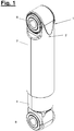
- Figure 1 and 2 show a cylinder (1) in a perspective external view and in a longitudinal section.
- the cylinder (1) has a cylinder seal (2) explained below.
- the cylinder (1) is designed as a fluidic cylinder, in particular as a hydraulic cylinder and furthermore as a double-tube cylinder.
- the cylinder (1) has a longitudinal axis or tube axis (9) and a piston rod (10) that can be retracted and extended in the axial direction. At its inner end, this has a piston arrangement (11) which is arranged in a cylinder interior and divides it into two working spaces.
- the piston arrangement (11) is equipped in the usual way with a throttle arrangement for the passage of a fluid located in the working spaces.
- connection (8) e.g. a bearing eye.
- the cylinder (1) can have an identical or different connection (8) connected to the cylinder body at the other and opposite end.
- the cylinder (1) is designed as a shock absorber. It is specially designed for high loads, e.g. in heavy-duty vehicles.
- the cylinder (1) and the cylinder seal (2) can also be designed and suitable for use under strongly fluctuating ambient conditions, in particular with high temperature differences of approx. -40 ° C to approx. 180 ° C.
- the double-tube cylinder (1) shown has an inner tube (3) and an outer tube (4) arranged at a radial distance therefrom.
- the inner tube (3) encloses the aforementioned inner cylinder space or working space.
- the cylinder (1) is closed at one end on the piston side by a solid base. At the other end of the cylinder (1) and towards the exit point of the piston rod (10) there is a cover (6) which at least partially closes the end and possibly also in connection with the cylinder seal (2).
- the lid (6) can, for example, be designed as a flanged edge of the outer tube (4).
- the cylinder (1) can also have a protective tube (7) which surrounds the outer tube (4) concentrically and at a small distance or tightly.
- the protective tube (7) is movable relative to the outer tube (4) and is connected to the piston rod (10) in a suitable manner. It can, for example, be slipped over the connection (8) and clipped onto the upper end of the piston rod (10).
- Figure 3 illustrates this arrangement.
- the cylinder (1) can be designed as a single-tube cylinder or in another suitable manner.
- the cylinder (1) shown has a circular design in cross section.
- another cross-sectional shape e.g. oval, prismatic or the like, is possible.
- the cylinder seal (2) shown in more detail has at least one sealing ring (12). It can also include a piston rod guide (13). Figures 13 and 14 as Figures 15 and 16 show two variants of the sealing ring (12).
- the cylinder seal (2) is arranged in the cylinder (1) on the end face on which the piston rod (10) also protrudes to the outside.
- the cylinder seal (2) serves to seal the oscillating piston rod (10) and also the face of the cylinder (1).
- the sealing ring (12) has a support ring (14) and a sealing means (21) which is fixedly arranged, in particular vulcanized, on the support ring (14).
- the sealing ring (12) is in one piece or as an individual
- the support ring (14) has an angled cross-sectional shape with a disk-like ring section (15) and a tubular ring section (16).
- the support ring (14) is made in one piece. It can be designed as a stamped and bent part, for example.
- the disk-like ring section (15) extends transversely to the longitudinal axis (9), it being possible for it to be oriented perpendicularly or obliquely to the longitudinal axis (9).
- the disk-like ring section (15) has an inner ring opening (17) on which the tubular ring section (16) is arranged.
- the tubular ring section (16) has a cylindrical shape and is aligned along the axis (9) or the piston rod (10).
- the ring sections (15, 16) merge into one another at the edge of the ring opening (17) with a preferably round bend (18). Alternatively, another training is possible.
- the tubular ring section (16) protrudes from the disk-shaped ring section (15) in the direction of the piston arrangement (11) and faces away from the said frontal cylinder end and the piston rod outlet.
- the support ring (14) can consist of a mechanically stable and temperature-resistant material, for example metal, in particular steel.
- the support ring (14) is designed, for example, as a thin-walled sheet metal part.
- the ring sections (15, 16) can have parallel inner and outer surfaces.
- the support ring (14) is self-supporting and inherently stable. It is attached to the piston rod (10) together with the sealant (21) during assembly.
- the tubular ring section (16) encloses the piston rod (10) to a certain extent lateral, in particular radial, spacing at which a sealing element (22) of the sealing means (21) explained below is clamped and held by the support ring (14).
- the tubular ring section (16) has an annular body that is closed in the circumferential direction.
- the ring body has a straight and, for example, cylindrical shape in its axial direction. In the installed position, it extends along the longitudinal axis (9). In the embodiment shown, the extension is concentric and parallel to the axis (9).
- the ring body for example, has a constant wall thickness and parallel inner and outer ring walls.
- the support ring (14), in particular the tubular ring section (16), has a smooth wall (20) at the ring opening (17). In the exemplary embodiment shown, this is a cylindrical wall.
- the wall (20) extends along the axis (9) in a straight direction and preferably has no projections directed towards the piston rod (10).
- the disk-like ring section (15) has the preferably circular ring opening (17) on the inside and on the outside a preferably circular outer edge (19) concentric to the axis (9).
- a preferably circular outer edge (19) concentric to the axis (9).
- another shape e.g. oval or prismatic, is possible.
- the inner contour of the tubular ring section (16) is adapted to the outer jacket contour of the piston rod (10).
- said contours are circular or cylindrical and concentric to the axis (9).
- the disc-shaped ring section (15) extends outward from the inner ring opening (17) transversely to the axis (9). In the installed position, it covers the free space between the central piston rod (10) and the inner circumference of the cylinder (1), in particular the inner tube (3). The cover acts on the front side to the outside in relation to the said edge flange of the outer tube (4).
- the sealing means (21) is preferably vulcanized onto the support ring (14) in the aforementioned manner.
- the sealing means (21) consists of a compressible and elastically deformable sealing material, in particular a plastic, preferably a polymer.
- the sealing material is suitable and designed for use in the entire said temperature range from approx. -40 ° C to approx. 180 ° C.
- the sealing material is designed, for example, as a fluorinated elastomer, in particular fluororubber, preferably fluorocarbon rubber (FKM).
- the sealing means (21) preferably has a plurality of sealing elements (22, 23, 24) which can be connected to one another.
- the sealing means (21) covers the support ring (14) on the circumferential side on the ring opening (17) and on the outer edge (19) as well as on the outside facing the cylinder end.
- the covering is continuous in the embodiment shown.
- the sealing means (21) has at least one inner and ring-like sealing element (22) which is provided and designed for sealing contact with the jacket of the piston rod (10). It is designed, for example, as a flexible sealing lip and is arranged on the ring opening (17), in particular on the inside of the tubular ring section (16).
- the inside sealing element (22) is supported on its outer circumference by the tubular ring section (16) and its wall (20).
- support can be provided in the axial direction (9), in particular at the free end of the tubular ring section (16).
- the inside sealing element (22) has two lip sections (25, 26) which protrude in the axial direction (9) on both sides beyond the tubular ring section (16).
- only a single lip section is possible, which protrudes on one side beyond the tubular ring section (16).
- the number of lip sections can also be greater than two.
- the lip section (25) points in the axial direction (9) to the adjacent cylinder end.
- it can form a dust protection lip.
- the lip section (26) points in the opposite direction to the piston rod guide (13). It protrudes axially beyond the free end of the ring section (16).
- the inside sealing element (22) makes contact with the piston rod (10) at the lip sections (25, 26).
- the circumference is preferably cylindrical and straight in the axial direction (9).
- the inside sealing element (22) has on its inner circumference, seen in cross section, a curved contour (40) which extends in the axial direction (9) and which bulges in a radial direction away from the piston rod (10).
- the arched contour (40) is arranged between the ends of the axially protruding lip sections (25, 26) as seen in the axial direction (9).
- the apex (41) of the arched contour (40) is level with the bend (18).
- projections (27, 28, 29) with a preferably radial or inclined orientation are arranged on the inner circumference of the inside sealing element (22). How Figure 5 and 9 to 11 To illustrate, the projections (27, 28, 29) form rings, for example.
- the local projections (27, 28, 29) which taper towards the inside of the axis (9) in cross-section are pointed or rounded are in contact with the jacket of the oscillating piston rod (10).
- At least two projections (27, 29) are located on the axially protruding lip sections (25, 26).
- One protrusion (27) is arranged, for example, at the end region of one lip section (25, 26) and another protrusion (29) is arranged at the end region of the other lip section (26).
- At least one such projection (27, 29) is axially spaced from the support ring (14).
- Both projections (27, 29) are preferably axially spaced from the support ring (14).
- the projection (29) on the lip section (26) in the direction of the piston rod guide (13) can have an axial distance from the free end of the ring section (16).
- a further projection (28) can be arranged on an area of the inside sealing element (22) which is located in the axial direction (9) at the level of the support ring (14), in particular the ring section (16).
- the lip sections (25, 26) with their projection (27, 29) can deform in their respective protruding area relative to the support ring (14) in a flexurally elastic manner transversely to the longitudinal axis (9) and to temperature-related changes in shape of the piston rod (10) and the support ring (14 ) and maintain the sealing effect.
- the projections (27, 28, 29) can be attached to the inside sealing element (22) in any suitable manner. You can, for example, from a solid material of Sealing element (22) can be worked out by reshaping, in particular cutting. This can take place after the sealing means (21) has been firmly connected to the support ring (14). Alternatively, other application techniques, for example by molding, are possible.
- tubular ring section (16) is embedded on the outer circumference of the inside sealing element (22). Its smooth wall (20) supports the sealing element (22) which rests here with its outer circumference in the radial direction.
- a radially outwardly projecting shoulder (30) on the outer circumference of the sealing element (22) covers the axial free edge of the tubular ring section (16).
- the extension (30) is formed, for example, on the lip section (26) protruding axially beyond the said free edge in the direction of the piston rod guide (13).
- the other surfaces of the support ring (14) facing the cylinder interior are, for example, not covered by the sealing means (21).
- This surface on the disk-like ring section (15) can serve for bearing and support purposes, e.g. when cutting the projections (27, 28, 29).
- the inside diameter of the tubular ring section (16) and the inside sealing element (22) are adapted to the outside diameter of the piston rod (10).
- the adaptation is such that, in the installed position, said sealing element (22) is clamped between the piston rod (10) and the tubular ring section (16).
- Figure 2 and 4th illustrate this arrangement.
- the sealing means (21) has, for example, a further sealing element (23) on the outside, which is preferably ring-like and designed as an outer sealing lip.
- a The annular element edge (23 '), in particular the edge of the sealing lip, can protrude and, in the installed position, point towards the adjacent cylinder end.
- the sealing element (23) on the outside serves to make a sealing contact with the cylinder (1) or with another part of the cylinder seal (2), in particular with a piston rod guide (13).
- the sealing element (23) is arranged on the outer edge (19) of the disk-like ring section (15).
- the sealing means (21) further comprises, for example, a ring-like sealing element (24) which is arranged between said inside and outside sealing elements (22,23) and covers one side of the disk-like ring section (15). This is the side facing the cylinder end and the exit point of the piston rod (10).
- This sealing element (24) can be designed as a thin-walled covering on the surface of the disk-like ring section (15).
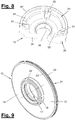
- the piston rod guide (13) has an in Figures 2 to 8 guide ring (31) shown in more detail.
- the guide ring (31) can be designed, for example, as a sintered component or as a printed 3-D molded body.
- the guide ring (31) is preferably made of metal.
- the sealing ring (12) is placed and supported on the guide ring (31) on its upper end face and is preferably guided in a form-fitting manner on the outer edge.
- Figures 6 and 7 illustrate this arrangement.
- the guide ring (31) has a central passage opening (36) for the piston rod (10).
- the guide ring (13) has an annular shape that is concentric to the axis (9) and is cylindrical.
- the guide ring (31) has an annular collecting channel (32) for the hydraulic fluid, which may pass the sealing ring (12) when the piston rod moves.
- the collecting channel (32) can have a recessed trough shape in cross section. There is preferably only a single collecting channel (32).
- the collecting channel (32) surrounds the passage opening (36) and connects to its annular wall.
- the opening point is in the area of the interspace (5) so that hydraulic fluid can radially emerge from the filled collecting duct (32) via the outlet duct (33), which is higher than the duct floor, and then flow downwards into the interspace (5).
- the height of the fluid in the collecting channel (32) is thereby limited.
- the guide ring (31) and its collecting channel (32) are covered by the sealing ring (12) floating above it at an axial distance.
- the guide ring (31) has a receiving means (34) in the form of a stepped ring base, for example, for receiving the sealing ring (12) in a form-fitting and sealing manner.
- Figure 5 , 6 and 7 illustrate this arrangement.
- the sealing ring (12) is supported in the axial direction (9) by the ring base and is enclosed on its outer circumference and guided radially on the outside.
- the ring base has a radially extending base surface (34 ') for supporting the sealing ring (12) and an annular base edge (34 ") projecting axially therefrom.
- the outer edge area of the sealing ring (12) rests on the receiving means (34) of the guide ring (31).
- the sealing ring (12) floats at an axial distance above the collecting channel (32) at the bottom and also above the outlet channel or channels (33) of the guide ring (31).
- the sealing ring (12) seals off this fluid receiving space in the axial direction to the cylinder face end and also in the transverse direction or radial direction.
- the sealing ring (12) preferably has no further physical contact with the guide ring (31) apart from the receiving means (34).
- the protruding lip section (26) of the inner sealing element (22) is axially spaced from the collecting channel (32) and from the annular wall there at the passage opening (36).
- the piston rod (10) is exposed in this area, where possible leakage of hydraulic fluid can escape and flow into the collecting channel (32).
- the cover (6) In the installed position, the cover (6), in particular the flanged edge of the outer tube (4), press the sealing ring (12) against the receiving means (34).
- the support ring (14) rests with its bare underside of the disk-like ring section (15) on the base surface (34 ′′) of the receiving means (34).
- the sealing elements (23, 24) are slightly squeezed by the cover (6) or the flanged edge and deformed to form a seal Figure 4 have an annular groove for the form-fitting and sealing reception of the upstanding lip edge (23 ').
- FIG. 14 a first variant of the sealing ring (12), in particular the support ring (14), is shown.
- the sealant (21) is in Figure 13 not shown.
- the tubular ring section (16) has a conical shape (37) in its axial direction. This is arranged concentrically to the axis (9) and can widen in the direction of the piston arrangement or taper towards the cover (6).
- the bend (18) is more curved than in the embodiment described above.
- the axial length of the tubular ring section (16) can be longer than in the previous exemplary embodiment, and the axial projection of the lip section (26) can be smaller.
- the conical ring section (16) can have a lower rigidity than in the previous embodiment.
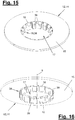
- Figures 15 and 16 show a further variant of the sealing ring (12), in particular of the support ring (14), in a respective perspective top and bottom view, the sealing means (21) not being shown for the sake of clarity.
- the support ring (14) has a tubular ring section (16) with an annular body which has a segmentation (38) in the circumferential direction.
- individual body sections or segments (39) are formed which can be connected to the disk-like ring section (15) at their foot region directed towards the transition point (18) or bend.
- the segments (39) can move transversely to the longitudinal axis (9) independently of one another as required.
- the segments (39) can be pre-bent or pre-tensioned starting from the ring opening (17) in the direction of the piston rod (10) and can exert a spring effect on the sealing means (21) in each case in the installed position.
- the segments (39) can be closely adjacent and, if necessary, butt against one another. Alternatively, they can be spaced apart, the resulting gaps being filled with sealant material.
Landscapes
- Engineering & Computer Science (AREA)
- General Engineering & Computer Science (AREA)
- Mechanical Engineering (AREA)
- Physics & Mathematics (AREA)
- Fluid Mechanics (AREA)
- Sealing Devices (AREA)
- Pistons, Piston Rings, And Cylinders (AREA)
- Sealing With Elastic Sealing Lips (AREA)
Abstract
Description
- Die Erfindung betrifft eine Zylinderdichtung für einen fluidischen Zylinder mit den Merkmalen im Oberbegriff des Hauptanspruchs.
- Eine solche Zylinderdichtung ist aus der
DE 60 2005 003 637 T2 bekannt. Sie weist einen einzelnen Dichtring auf, der von einem abgewinkelten Stützring aus Kunststoff mit einem allseitig umgebenden und an Vorsprüngen oder Schlitzen verankerten Dichtmittel gebildet wird. Der Dichtring ist direkt einem Öldruck im Zylinder ausgesetzt, welcher mit einer Radialkomponente auch auf eine Dichtlippe wirkt und diese gegen die Kolbenstange drückt. Der Stützring hat einen flexiblen konischen Ansatz, welcher der besagten Radialkomponente des Öldrucks entgegenwirkt und die Dichtlippe entlastet. - Die
EP 2 418 394 A1 betrifft eine Zylinderdichtung, die eine am Zylinderende montierte Kolbenstangenführung mit einem Führungsring und einen Dichtring aufweist, der als Endanschlag für den Kolben dient und in einem topfartig vertiefen zentralen Sitz des Führungsrings aufgenommen und eingespannt ist. Der Dichtring umfasst einen abgewinkelten Stützring mit einem umgebenden Dichtmittel und einer innenseitigen Dichtlippe, die zwischen dem Sitz und der Kolbenstange eingespannt ist. Der Dichtring weist im Sitzbereich einen versteiften Gleitring zur Führung der Kolbenstange auf, der in einer Aussparung am Innenumfang der Dichtlippe angeordnet ist. Der Dichtring liegt rund um den zentralen Sitz großflächig und plan auf dem massiven Führungsring auf und hat einen zum Kolben weisenden ringartigen Vorsprung mit radialen Ausnehmungen zur Ölverdrängung bei Anschlag des Kolbens. - Die
US 2006/0213734 A1 zeigt eine andere Zylinderdichtung mit einem Dichtring, der von einem ringscheibenartigen Stützring und einer nur an der inneren Scheibenringöffnung angeordneten Dichtlippe gebildet wird. Der Stützring ist an seinem äußeren Ringumfang zwischen einer Kolbenstangenführung, einem äußeren Zylinderrohr und einem Deckel angespannt. - Die
EP 2 116 738 B1 zeigt einen ähnlichen Dichtring mit einem ringscheibenartigen Stützring und einem darauf angeordneten Stützmittel. Ein inneres dichtlippenartiges Dichtungselement liegt am Mantel der Kolbenstange an und wird an einem axial frei abstehenden Lippenabschnitt und dessen außenseitigen Vorsprung mittels einer Kolbenstangenführung gegen die Kolbenstange gepresst. - Die
DE 38 31 719 A1 zeigt eine Zylinderdichtung mit einem ringartig profilierten Dichtungskörper, der innenseitig an der Kolbenstange anliegt und außenseitig an einer Kolbenstangenführung aufgenommen ist. Der Dichtungskörper weist eine an der Kolbenstange anliegende Dichtlippe auf, an der außenseitig ein schmaler Spannring aufgezogen ist. Am Spannring kann ein O-Ring oder ein Federring angeordnet sein. - Es ist Aufgabe der vorliegenden Erfindung, eine verbesserte Abdichtmöglichkeit für Zylinder aufzuzeigen.
- Die Erfindung löst diese Aufgabe durch eine Zylinderdichtung mit den Merkmalen des Hauptanspruchs und durch einen mit einer solchen Zylinderdichtung ausgerüsteten Zylinder.
- Die Zylinderdichtung und der damit ausgerüstete Zylinder haben verschiedene Vorteile.
- Der Zylinder kann als fluidischer Zylinder, insbesondere Hydraulikzylinder ausgebildet sein. Er kann insbesondere als Stoßdämpfer für Schwerlastfahrzeuge eingesetzt werden. Die beanspruchte Zylinderdichtung und der damit ausgerüstete Zylinder, insbesondere Stoßdämpfer, halten unterschiedlichste und im Betrieb ggf. auch variierende Umgebungs- und Einsatzbedingungen aus. Dies betrifft z.B. extreme klimatische Umgebungseinflüsse und/oder hohe mechanische Belastungen. Sie haben insbesondere einen sehr breiten thermischen Einsatzbereich von ca. -40°C bis ca. +180°C. Die Minustemperaturen können z.B. nachts in Polarzonen und im Stand eines Fahrzeugs einwirken. Die genannten hohen Temperaturen können im Zylinder bei einem Schwerlast-Fahrbetrieb und auf Off-Road-Strecken erreicht werden. Im Betrieb kann der gesamte Temperaturbereich durchfahren werden. Die beanspruchte Zylinderdichtung behält trotz dieser großen Temperaturschwankungen ihre Dichtwirkung. Für einen Schwerlastzylinder mit den dort herrschenden hohen Kräften und Drücken ist dies von besonderem Vorteil. Der Zylinder und die Zylinderdichtung können für einen Einsatz unter solchen stark schwankenden Umgebungsbedingungen, insbesondere mit den besagten hohen Temperaturunterschieden geeignet und ausgebildet sein.
- Die Zylinderdichtung kann die ein- und ausfahrbare Kolbenstange gegen einen Fluidaustritt sicher und nachhaltig abdichten. Sie kann außerdem eine Dichtwirkung für den Zylinderinnenraum und das stirnseitige Zylinderende ausüben. Die Zylinderdichtung wird bevorzugt innenseitig im Zylinder an dem bzgl. der Zylinder- oder Rohrachse stirnseitigen Zylinderende mit der dort austretenden Kolbenstange angeordnet. Das Fluid kann eine Hydraulikflüssigkeit, insbesondere Hydrauliköl, sein.
- Die Zylinderdichtung umfasst zumindest einen Dichtring. Sie kann zusätzlich eine Kolbenstangenführung beinhalten. Dichtring und Kolbenstangenführung können getrennt oder gemeinsam lieferbare Produkte darstellen. Der Dichtring kann an einer vorhandenen Kolbenstangenführung nachgerüstet oder umgerüstet werden.
- Der beanspruchte Dichtring weist einen Stützring und ein Dichtungsmittel auf, welches auf dem Stützring angeordnet ist. Das Dichtungsmittel kann den Stützring größtenteils bedecken. Der Dichtring besteht aus wenigen, insbesondere nur zwei, Komponenten. Er ist einfach und kostengünstig herstellbar.
- Der Stützring hat eine abgewinkelte Querschnittsform mit einem scheibenartigen Ringabschnitt und einem rohrartigen Ringabschnitt, wobei der rohrartige Ringabschnitt an der inneren Ringöffnung des scheibenartigen Ringabschnitts angeordnet ist. Der abgewinkelte Stützring kann die Form eines Rohrflansches haben. Er kann z.B. als gelochtes und gebogenes Blechteil mit ggf. konstanter Wanddicke ausgebildet sein.
- Der Stützring kann auf der Kolbenstange mit dem rohrartigen Ringabschnitt aufgesteckt und montiert sowie gehalten werden. Der abgewinkelte Stützring ist eigensteif und selbsttragend. Er kann ansonsten an seiner äußeren Umfangsseite am Zylinder und/oder an einer Kolbenstangenführung abgestützt und eingespannt sein, z.B. durch einen Deckel des Zylinders, insbesondere eine Randumbördelung eines Zylinderrohrs. An dieser Abstützstelle kann ebenfalls das Dichtungsmittel vorhanden und wirksam sein.
- Der rohrartige Ringabschnitt erstreckt sich in Einbaustellung entlang der Kolbenstange. Die Erstreckung kann konzentrisch und parallel zur Kolbenstange bzw. zur Zylinderachse verlaufen. Alternativ kann der rohrartige Ringabschnitt eine konzentrische Konusform haben. Diese kann sich bevorzugt in Richtung zur Kolbenanordnung erweitern. Alternativ ist eine gegenläufige Erweiterung möglich.
- Der rohrartige Ringabschnitt kann einen Ringkorpus aufweisen, der in Umfangsrichtung geschlossen oder segmentiert ist. Bei einer geschlossenen Ausbildung ergibt sich eine höhere Steifigkeit. Eine segmentierte Ausbildung ermöglicht eine quer zur Zylinder- oder Rohrachse, insbesondere in einer Radialrichtung, bestehende Federwirkung. Die Korpussegmente können in Richtung auf die Kolbenstange vorgebogen oder vorgespannt sein und können einzeln eine Federwirkung entfalten. Dies ist für das an der Kolbenstange angreifende Dichtungsmittel und die Dichtwirkung vorteilhaft. Insbesondere bei größeren Temperaturschwankungen ist eine solche segmentiert federende Dichtwirkung von großem Vorteil.
- Die Innenkontur der Ringöffnung, insbesondere des rohrartigen Ringabschnitts, ist an die äußere Mantelkontur der Kolbenstange angepasst. Überlicherweise ist die Kolbenstange zylindrisch, wobei auch die Ringöffnung kreisrund ist bzw. der rohrartige Ringabschnitt an der Innenseite zylindrisch ausgebildet ist. Alternativ kann die Kolbenstange eine andere z.B. ovale oder prismatische Querschnittsform aufweisen mit entsprechender Formanpassung des rohrartigen Ringabschnitts bzw. der inneren Ringöffnung.
- Der von der Ringöffnung nach außen erstreckte scheibenförmige Ringabschnitt ist dazu vorgesehen und ausgebildet, in Einbaustellung den Freiraum zwischen der zentralen Kolbenstange und dem Innenumfang des Zylinders zumindest weitestgehend abzudecken. Der scheibenförmige Ringabschnitt hat hierfür eine entsprechend große und z.B. radiale Erstreckung nach außen. Dies ermöglicht auch eine außenseitige axiale Abstützung und ggf. Einspannung des Stützrings an der Peripherie einer Kolbenstangenführung oder an der Peripherie des Zylinders.
- Das Dichtungsmittel ist auf dem Stützring bevorzugt fest angeordnet. Es kann insbesondere aufvulkanisiert sein. Durch die innige Verbindung von Dichtungsmittel und Stützring ist der Dichtring einteilig und als einzelnes Komplettbauteil ausgebildet. Er kann dadurch besonders leicht und einfach gehandhabt und montiert werden.
- Der Stützring kann aus einem beliebig geeigneten Material, insbesondere einem Metall, z.B. Stahl, bestehen. Das Dichtungsmittel besteht aus einem geeigneten Dichtwerkstoff, z.B. einem Kunststoff, insbesondere einem kompressiblen und verformbaren Polymer. Der Stützring und das Dichtungsmittel sind für den besagten sehr breiten thermischen Einsatzbereich von ca. -40°C bis ca. +180°C ausgelegt. Als Dichtwerkstoff sind hierfür fluorierte Elastomere, insbesondere Fluorkautschuke, z.B. Fluorkarbonkautschuk, vorteilhaft.
- Das Dichtungsmittel weist zumindest ein innenseitiges und bevorzugt ringartiges Dichtungselement auf, das zur dichtenden Anlage am Mantel der Kolbenstange vorgesehen und ausgebildet ist. Das Dichtungsmittel kann ein oder mehrere weitere Dichtungselemente aufweisen, die bevorzugt miteinander verbunden sind. Alternativ können sie getrennt und stellenweise vorhanden sein.
- Das Dichtungsmittel bedeckt vorzugsweise einen Großteil der Außenfläche des Stützrings. Das Dichtungsmittel kann den Stützring jeweils umfangseitig an der Ringöffnung und am Außenrand sowie an der zum Zylinderende weisenden Außenseite bedecken. Diese Bedeckung kann großteils, vorzugsweise durchgängig, vorhanden sein. Hierdurch hat der Dichtring zumindest an der zum Zylinderende weisenden Außenseite eine bevorzugt durchgängige Dichtwirkung.
- Das innenseitige Dichtungselement kann z.B. als flexible Dichtlippe ausgebildet sein. Es ist an der Ringöffnung, insbesondere an der Innenseite des rohrartigen Ringabschnitts, angeordnet. Es kann vom rohrartigen Ringabschnitt abgestützt sein, insbesondere an seiner Rückseite bzw. an seinem Außenumfang.
- Die Abstützwirkung kann an dem zur Kolbenstange weisenden Außenumfang des Dichtungselements und ggf. zusätzlich in Axialrichtung vorhanden sein. Für eine Ausbildung als flexible Dichtlippe ist diese Abstützung am rohrartigen Ringabschnitt besonders vorteilhaft. Der Ringabschnitt kann mit seiner bevorzugt glattwandigen Ausbildung eine besonders gute und gleichmäßige Abstützwirkung für das anliegende Dichtungselement, insbesondere die flexible Dichtlippe, entfalten. Dies ist besonders bei großen Temperaturunterschieden von Vorteil.
- Der rohrartige Ringabschnitt hält durch seine die Kolbenstange in Einbaustellung umschließende Rohrform das besagte Dichtungselement bzw. die Dichtlippe in der Abdichtstellung an der axial oszillierend beweglichen Kolbenstange. Die axiale Länge des rohrförmigen Ringabschnitts kann an die gewünschte Stützwirkung angepasst werden. Die erwähnte segmentierte Ausbildung des Ringkorpus ist in diesem Zusammenhang ebenfalls von großem Vorteil.
- Das innenseitige Dichtungselement, insbesondere die Dichtlippe, kann einen oder mehrere, insbesondere zwei, Lippenabschnitte aufweisen, die in Axialrichtung einseitig oder beidseitig über den Stützring, insbesondere den rohrartigen Ringabschnitt, hinausragen. Dieser jeweils elastisch verformbare Lippenabschnitt kann durch den axialen Überstand eine Federwirkung haben und kann ebenfalls vorteilhaft auf Temperaturschwankungen reagieren und die Dichtwirkung aufrecht erhalten. Der jeweilige Lippenabschnitt kann am axialen Überstand für eine dichtende Anlage am Mantel der Kolbenstange ausgebildet sein.
- Das besagte innere Dichtungselement, insbesondere die Dichtlippe, kann eine zur Kolbenstange konzentrische Ringform aufweisen. Im Querschnitt kann dabei eine von der Kolbenstange nach außen gewölbte Formgebung bestehen. Das innenseitige Dichtungselement kann mehrere bevorzugt radiale Vorsprünge aufweisen, die für eine besonders gute und sichere Anlage und Dichtwirkung am Mantel der Kolbenstange sorgen. Ein oder mehrere Vorsprünge können jeweils an einem oder beiden axial überstehenden Lippenabschnitten angeordnet sein. Der oder die Vorsprünge können vom benachbarten Endbereich des Stützrings in Axialrichtung beabstandet sein. Der über das freie Ende des rohrartigen Ringabschnitts axial hinausragende Lippenabschnitt kann mit einem ebenfalls vom freien Ende distanzierten Vorsprung besonders gut und nachhaltig im genannten Temperaturbereich dichtend an der Kolbenstange anliegen. Die besagte Federwirkung des axialen Überstands ist von besonderem Vorteil.
- Der rohrartige Ringabschnitt kann am Außenumfang des innenseitigen Dichtungselements, insbesondere der Dichtlippe, anliegen und eingebettet sein. Ein Ansatz kann den axialen freien Rand des rohrartigen Ringabschnitts bedecken. Der Ansatz kann an einem axial überstehenden Lippenabschnitt angeordnet sein, z.B. als radialer Vorsprung an dessen Außenseite oder Rückseite. Die Einbettung und Abdeckung kann besonders gut durch ein Aufvulkanisieren des Dichtungsmittels gebildet werden.
- In der Einbausstellung des Dichtrings wird das innenseitige Dichtungselement, insbesondere die Dichtlippe zwischen der Kolbenstange und dem rohrartigen Ringabschnitt eingespannt. Der formsteife und im Innendurchmesser adaptierte Rohrabschnitt presst das eingespannte innenseitige Dichtungselement in definierter Weise und mit nachhaltiger Dichtwirkung über den besagten breiten Temperaturbereich an die Kolbenstange. Hierfür ist die selbsttragende Ausbildung des Dichtrings von Vorteil.
- Die Anpresswirkung und die Anpresskräfte können ausschließlich aus dem rohrartigen Ringabschnitt und dessen Gestaltung entwickelt werden. Ein zusätzliches außenseitigen Andrücken des Dichtungselements durch eine Kolbenstangenführung wie bei der
EP 2 116 738 B1 oder durch einen besonderen Spannring oder Federring wie bei derDE 38 31 719 A1 , sind entbehrlich. Die vom rohrartigen Ringabschnitt entwickelte Führung und Anpressung des Dichtungselements ist besser und zuverlässiger, insbesondere bei stark schwankenden Temperaturen. Eine segmentierte Ausbildung des Rohrkörpers kann auch hier besondere Vorteile haben. - Das Dichtungsmittel kann ferner ein außenseitiges Dichtungselement aufweisen, das zur dichtenden Anlage am Zylinder oder an einem anderen Teil der Zylinderdichtung, insbesondere einer etwaigen Kolbenstangenführung, vorgesehen und ausgebildet ist. Günstig ist dabei eine ringartige Ausbildung des Dichtungselements. Dieses kann am umfangseitigen Außenrand des scheibenartigen Ringabschnitts angeordnet sein und dichtet diesen gegenüber der Umgebung ab. Eine Ausbildung des Dichtungselements als Dichtlippe ist ebenfalls von Vorteil. Bei der Montage kann durch die Lippenverformung eine besonders gute Dichtwirkung für den in sich steifen Stützring erreicht werden.
- Das Dichtungsmittel kann ferner ein Dichtungselement aufweisen, das zwischen dem innenseitigen und dem außenseitigen Dichtungselement auf dem scheibenartigen Ringabschnitt angeordnet ist und eine bevorzugt zum stirnseitigen Zylinderende weisende Oberseite dieses scheibenartigen Ringabschnitts bedeckt. Das ebenfalls vorzugsweise ringartige Dichtungselement kann mit den äußeren und inneren, bevorzugt lippenartigen Dichtungselementen einstückig verbunden sein, insbesondere durch eine Vulkanisierung.
- Die Zylinderdichtung kann die vorgenannte Kolbenstangenführung aufweisen. Diese besitzt einen Führungsring, der zur seitlichen bzw. radialen Führung der oszillierenden Kolbenstange dient.
- Der Führungsring weist eine einfache und besonders kostengünstig herstellbare Bauform auf. Er kann einteilig ausgebildet sein und durch Sintern oder 3D-Druck produziert werden.
- Der Führungsring kann eine Durchlassöffnung für die Kolbenstange, einen bevorzugt einzelnen und ringförmigen Sammelkanal für das Fluid, insbesondere Hydraulikflüssigkeit, und einen oder mehrere dort angeschlossene und an der Außenseite des Führungsrings mündende Auslasskanäle aufweisen. Diese verbinden den Sammelkanal mit einem, Zwischenraum zwischen einem Innenrohr und einem Außenrohr des Zylinders in der bevorzugten Ausbildung als Doppelrohrzylinder. Evtl. durch die Kolbenstangenführung tretende Fluidteile können dadurch abgeführt und der Kolbenanordnung am anderen und inneren Ende der Kolbenstange zugeführt werden. Der bevorzugt zur Kolbenstange mittensymmetrische Sammelkanal kann auch mehrfach vorhanden sein.
- Der Dichtring kann auf der Kolbenstangenführung stirnseitig angeordnet werden. Er kann auf der Kolbenstangenführung in axialer Richtung abgestützt und quer dazu, insbesondere in Radialrichtung, geführt sein. Der Dichtring kann auf der Kolbenstangenführung lose oder mit leichtem Klemmschluss über das äußere ringartige Dichtungsmittel aufliegen. Das äußere ringartige Dichtungsmittel kann außenseitig an der Kolbenstangenführung anliegen und hierüber radial geführt sein. Die Kolbenstangenführung übt dabei keine signifikanten Querkräfte oder Radialkräfte auf den Stützring aus und hat auch keinen Einfluss auf die Anpressung des inneren ringartigen und lippenartigen Dichtungselements an der Kolbenstange. Hierfür ist ausschließlich der rohrartige Ringabschnitt des eigensteifen Stützrings vorgesehen und verantwortlich.
- Der Dichtring kann in seiner Lage am Stirnende der Kolbenstangenführung gesichert werden, z.B. durch einen Deckel, insbesondere eine Randumbördelung, des Zylinders. Ansonsten schwebt der Dichtring über dem bodenseitigen Sammelkanal des Führungsrings und dichtet diesen Fluidaufnahmeraum in Axialrichtung zum stirnseitigen Zylinderende und auch in Querrichtung bzw. Radialrichtung ab. Der Fluidaufnahmeraum ist vom hohen Fluiddruck im Zylinderinnenraum entkoppelt. Der Kontaktbereich zwischen dem Dichtring und der Kolbenstangenführung kann sich auf die Abstützung und Führung am Außenrand des Dichtrings beschränken.
- Der Führungsring kann im Zylinder und an dessen stirnseitigem Ende in beliebig geeigneter Weise angeordnet und geführt bzw. fixiert sein. Bei einer Ausbildung als Doppelrohrzylinder kann der Führungsring auf dem axial verkürzten Innenrohr aufsitzen und kann durch den besagten Deckel, insbesondere die Randumbördelung des Außenrohrs, in Position gehalten und ggf. eingespannt werden.
- In den Unteransprüchen sind weitere vorteilhafte Ausgestaltungen der Erfindung angegeben.
- Die beanspruchte Zylinderdichtung und der damit ausgerüstete Zylinder können folgende Ausgestaltungen aufweisen, die einzeln oder in beliebiger Kombination eingesetzt werden können.
- Die Ringabschnitte des abgewinkelten Stützrings des Dichtrings können quer zueinander, insbesondere senkrecht zueinander, ausgerichtet sein.
- Die Ringabschnitte des abgewinkelten Stützrings des Dichtrings können am Rand der inneren Stützringöffnung mit einer bevorzugt runden Biegung ineinander übergehen.
- Der rohrartige Ringabschnitt des Stützrings kann in Axialrichtung eine gerade, bevorzugt zylindrische, Form oder eine Konusform aufweist. Bevorzugt erweitert sich die Konusform vom scheibenartigen Ringabschnitt ausgehend und in Richtung zur Kolbenstangenführung.
- Die Innenkontur des rohrartigen Ringabschnitts des Stützrings kann an die äußere Mantelkontur der Kolbenstange angepasst sein.
- Der von der inneren Stützringöffnung nach außen erstreckte scheibenförmige Ringabschnitt des Stützrings kann dazu vorgesehen und ausgebildet sein, in Einbaustellung den Freiraum zwischen der zentralen Kolbenstange und dem Innenumfang des Zylinders zumindest weitestgehend abzudecken.
- Das Dichtungsmittel des Dichtrings kann mehrere, bevorzugt miteinander verbundene, Dichtungselemente aufweisen.
- Das innenseitige Dichtungselement kann an seinem Außenumfang einen radial oder schräg nach außen vorspringenden Ansatz aufweisen, der einen axialen freien Rand des rohrartigen Ringabschnitts bedeckt. Des Ringabschnitt kann am Außenumfang des innenseitigen Dichtungselements befestigt, insbesondere eingebettet, sein.
- Der Innendurchmesser des rohrartigen Ringabschnitts und das innenseitige Dichtungselement, insbesondere dessen Innenumfang, können an den Außendurchmesser der Kolbenstange angepasst sind. Diese Anpassung kann derart sein, dass das innenseitige Dichtungselement zwischen der Kolbenstange und dem rohrartigen Ringabschnitt eingespannt wird.
- Das Dichtungsmittel kann mehrere, ggf. miteinander verbundene Dichtungselemente aufweisen. Das Dichtungsmittel kann ein bevorzugt ringartiges Dichtungselement aufweisen, das zwischen einem innenseitigen und einem außenrandseitigen Dichtungselement angeordnet ist und eine Seite des scheibenartigen Ringabschnitts bedeckt.
- Der mit der Zylinderdichtung ausgerüstete Zylinder kann als Doppelrohrzylinder ausgebildet sein. Die Zylinderdichtung kann dabei zwischen einem Innenrohr und einem Deckel am Zylinderende angeordnet, insbesondere eingespannt, sein.
- Der Dichtring kann nur an einem außenrandseitigen und bevorzugt sockelartigen Aufnahmemittel des Führungsrings einen Berührungskontakt mit dem Führungsring haben. Der Dichtring kann hier axial abgestützt und an seinem Außenumfang von außen her radial und ggf. mit leichtem Klemmschluss über ein randseitiges Dichtungselement geführt sein. An den anderen Bereichen, insbesondere im Bereich des innenseitigen Dichtungselements, kann der Dichtring mit Führungsring nicht in Berührungskontakt stehen. Der Dichtring und kann hier vom Führungsring distanziert sein.
- Die Erfindung ist in den Zeichnungen beispielhaft und schematisch dargestellt. Im Einzelnen zeigen:
- Figur 1:
- einen Zylinder mit einer innenseitigen, verborgenen Zylinderdichtung in einer perspektivischen Außenansicht,
- Figur 2:
- den Zylinder mit der Zylinderdichtung von
Figur 1 in einem Längsschnitt, - Figur 3:
- eine vergrößerte geschnittene und perspektive Darstellung der Zylinderdichtung und ihrer Einbaustellung am stirnseitigen Zylinderende und an der Austrittsseite einer oszillierenden Kolbenstange,
- Figur 4:
- eine vergrößerte Darstellung eines Ausschnitts IV von
Figur 2 , - Figur 5:
- eine Zylinderdichtung mit einem Dichtring und einer Kolbenstangenführung in einem Querschnitt und in Montagestellung,
- Figur 6:
- eine perspektivische Ansicht der Zylinderdichtung an einer abgebrochen dargestellten Kolbenstange,
- Figur 7:
- eine Explosionsdarstellung der Zylinderdichtung mit ihrem Dichtring und einer Kolbenstangenführung,
- Figur 8:
- eine perspektivische und teilweise geschnittene Darstellung eines Führungsrings der Kolbenstangenführung,
- Figur 9:
- eine perspektivische Außenansicht des Dichtrings,
- Figur 10:
- den Dichtring von
Figur 9 in einer Frontansicht, - Figur 11:
- einen Querschnitt durch den Dichtring gemäß Schnittlinie XI/XI von
Figur 10 , - Figur 12:
- eine vergrößerte Darstellung des Details II von
Figur 11 , - Figur 13 und 14:
- eine Variante des Dichtrings in verschiedenen Ansichten und
- Figur 15 und 16:
- eine weitere Variante des Dichtrings in verschiedenen Ansichten.
- Die Erfindung betrifft eine Zylinderdichtung (2) für einen Zylinder (1), insbesondere einen Doppelrohrzylinder. Die Erfindung betrifft ferner einen mit einer Zylinderdichtung (2) ausgerüsteten Zylinder (1).
-
Figur 1 und2 zeigen einen Zylinder (1) in perspektivischer Außenansicht und in einem Längsschnitt. Der Zylinder (1) weist eine nachfolgend erläuterte Zylinderdichtung (2) auf. - Der Zylinder (1) ist im Ausführungsbeispiel als fluidischer Zylinder, insbesondere als Hydraulikzylinder und im Weiteren als Doppelrohrzylinder ausgebildet. Der Zylinder (1) weist eine Längsachse oder Rohrachse (9) und eine in Axialrichtung ein- und ausfahrbare Kolbenstange (10) auf. Diese weist an ihrem inneren Ende eine Kolbenanordnung (11) auf, die in einem Zylinderinnenraum angeordnet ist und diesen in zwei Arbeitsräume unterteilt.
- Die Kolbenanordnung (11) ist in üblicher Weise mit einer Drosselanordnung für den Durchlass eines in den Arbeitsräumen befindlichen Fluids ausgestattet.
- Das andere freie und außerhalb des Zylinderinnenraums befindliche Ende der Kolbenstange (10) ist mit einem Anschluss (8), z.B. einem Lagerauge, verbunden. Der Zylinder (1) kann am anderen und gegenüberliegenden Ende eine mit dem Zylinderkorpus verbundenen gleichen oder anderen Anschluss (8) aufweisen.
- Der Zylinder (1) ist in der gezeigten Ausführungsform als Stoßdämpfer ausgebildet. Er ist besonders für hohe Belastungen, z.B. bei Schwerlastfahrzeugen, ausgelegt. Der Zylinder (1) und die Zylinderdichtung (2) können außerdem für einen Einsatz unter stark schwankenden Umgebungsbedingungen, insbesondere mit hohen Temperaturunterschieden von ca. -40°C bis ca. 180°C ausgebildet und geeignet sein.
- Der gezeigte Doppelrohrzylinder (1) weist ein Innenrohr (3) und ein mit radialem Abstand dazu angeordnetes Außenrohr (4) auf. Das Innenrohr (3) umschließt den vorgenannten inneren Zylinderraum bzw. Arbeitsraum. Zwischen den parallelen und konzentrischen Rohren (3,4) ist ein z.B. ringförmiger Zwischenraum (5) vorhanden, in den an der Zylinderdichtung (2) und an der Kolbenstange (10) austretende Hydraulikflüssigkeit, insbesondere Hydrauliköl eintreten und zur Kolbenanordnung (11) zurückfließen kann.
- Der Zylinder (1) ist am einen kolbenseitigen Ende durch einen festen Boden verschlossen. Am anderen und zur Austrittstelle der Kolbenstange (10) gelegenen Stirnende des Zylinders (1) ist ein Deckel (6) vorhanden, der die Stirnseite zumindest teilweise und ggf. auch in Verbindung mit der Zylinderdichtung (2) verschließt. Der Deckel (6) kann z.B. als Randumbördelung des Außenrohrs (4) ausgebildet sein.
- Der Zylinder (1) kann ferner ein Schutzrohr (7) aufweisen, welches das Außenrohr (4) konzentrisch und mit geringem Abstand bzw. dicht umschließt. Das Schutzrohr (7) ist relativ zum Außenrohr (4) beweglich und ist mit der Kolbenstange (10) in geeigneter Weise verbunden. Es kann z.B. über den Anschluss (8) gestülpt und am oberen Ende der Kolbenstange (10) eingeclipst sein.
Figur 3 verdeutlicht diese Anordnung. - Der Zylinder (1) kann in einer anderen Ausführungsform als Einrohrzylinder oder in anderer geeigneter Weise ausgebildet sein. Der gezeigte Zylinder (1) hat im Querschnitt eine kreisrunde Ausbildung. Alternativ ist eine andere Querschnittsform, z.B. oval, prismatisch oder dergleichen möglich. Gleiches gilt für die Querschnittsform der Kolbenstange (10), die im gezeigten Ausführungsbeispiel zylindrisch ist.
- Die in
Figur 3 bis 12 näher dargestellte Zylinderdichtung (2) weist zumindest einen Dichtring (12) auf. Sie kann außerdem eine Kolbenstangenführung (13) umfassen.Figur 13 und 14 sowieFigur 15 und 16 zeigen zwei Varianten des Dichtrings (12). - Die Zylinderdichtung (2) ist im Zylinder (1) an dessen Stirnseite angeordnet, an der auch die Kolbenstange (10) nach außen tritt. Die Zylinderdichtung (2) dient zur Abdichtung der oszillierenden Kolbenstange (10) und auch der Stirnseite des Zylinders (1).
- Der Dichtring (12) weist einen Stützring (14) und ein Dichtungsmittel (21) auf, welches auf dem Stützring (14) fest angeordnet, insbesondere aufvulkanisiert ist. Der Dichtring (12) ist einteilig bzw. als einzelnes
- Komplettbauteil ausgebildet.
- Wie insbesondere
Figuren 9 bis 12 verdeutlichen, weist der Stützring (14) eine abgewinkelte Querschnittsform mit einem scheibenartigen Ringabschnitt (15) und einem rohrartigen Ringabschnitt (16) auf. Der Stützring (14) ist einteilig ausgebildet. Er kann z.B. als Stanz- und Biegeteil ausgeführt sein. - Der scheibenartige Ringabschnitt (15) erstreckt sich quer zur Längsachse (9), wobei er senkrecht oder schräg zur Längsachse (9) ausgerichtet sein kann. Der scheibenartige Ringabschnitt (15) weist eine innere Ringöffnung (17) auf, an welcher der rohrartige Ringabschnitt (16) angeordnet ist. Der rohrartige Ringabschnitt (16) hat in der gezeigten Ausführungsform eine zylindrische Form und ist längs der Achse (9) bzw. der Kolbenstange (10) ausgerichtet.
- Die Ringabschnitte (15,16) gehen am Rand der Ringöffnung (17) mit einer bevorzugt runden Biegung (18) ineinander über. Alternativ ist eine andere Ausbildung möglich. Der rohrartige Ringabschnitt (16) steht vom scheibenförmigen Ringabschnitt (15) in Richtung zur Kolbenanordnung (11) ab und weist vom besagten stirnseitigen Zylinderende und dem Kolbenstangenaustritt weg.
- Der Stützring (14) kann aus einem mechanisch stabilen und temperaturfesten Material, z.B. Metall, insbesondere Stahl, bestehen. Der Stützring (14) ist z.B. als dünnwandiges Blechteil ausgebildet. Die Ringabschnitte (15, 16) können parallele Innen- und Außenflächen aufweisen. Der Stützring (14) ist selbsttragend und eigenstabil ausgebildet. Er wird mitsamt des Dichtungsmittels (21) bei der Montage auf der Kolbenstange (10) aufgesteckt. Der rohrartige Ringabschnitt (16) umschließt dabei die Kolbenstange (10) mit einem gewissen seitlichen, insbesondere radialen, Abstand, in dem ein nachfolgend erläutertes Dichtungselement (22) des Dichtungsmittels (21) eingespannt und vom Stützring (14) gehalten wird.
- Der rohrartige Ringabschnitt (16) weist in der gezeigten Ausführungsform einen in Umfangsrichtung geschlossenen Ringkorpus auf. Der Ringkorpus hat in seiner Axialrichtung eine gerade und z.B. zylindrische Form. Er erstreckt sich in Einbaustellung entlang der Längsachse (9). In der gezeigten Ausführung ist die Erstreckung konzentrisch und parallel zur Achse (9). Der Ringkorpus hat z.B. eine konstante Wanddicke und parallele innere und äußere Ringwände.
- Der Stützring (14), insbesondere der rohrartige Ringabschnitt (16), weist an der Ringöffnung (17) eine glatte Wandung (20) auf. Dies ist im gezeigten Ausführungsbeispiel eine zylindrische Wandung. Die Wandung (20) erstreckt sich längs der Achse (9) in gerader Richtung und hat bevorzugt keine zur Kolbenstange (10) gerichteten Vorsprünge.
- Der scheibenartige Ringabschnitt (15) weist die bevorzugt kreisrunde Ringöffnung (17) an der Innenseite und an der Außenseite einen bevorzugt kreisrunden und zur Achse (9) konzentrischen Außenrand (19) auf. Alternativ ist eine andere, z.B. ovale oder prismatische Formgebung möglich.
- Die Innenkontur des rohrartigen Ringabschnitts (16) ist an die äußere Mantelkontur der Kolbenstange (10) angepasst. Im gezeigten Ausführungsbeispiel sind die besagten Konturen kreisrund bzw. zylindrisch und konzentrisch zur Achse (9).
- In der in
Figur 3 und4 gezeigten Einbaustellung erstreckt sich der scheibenförmige Ringabschnitt (15) von der inneren Ringöffnung (17) quer zur Achse (9) nach außen. Er deckt dabei in Einbaustellung den Freiraum zwischen der zentralen Kolbenstange (10) und dem Innenumfang des Zylinders (1), insbesondere des Innenrohrs (3) ab. Die Abdeckung wirkt an der Stirnseite nach außen gegenüber der besagten Randumbördelung des Außenrohrs (4). - Das Dichtungsmittel (21) ist auf dem Stützring (14) in der erwähnten Weise bevorzugt aufvulkanisiert. Das Dichtungsmittel (21) besteht aus einem kompressiblen und elastisch verformbaren Dichtmaterial, insbesondere aus einem Kunststoff, vorzugsweise einem Polymer. Das Dichtmaterial ist für den Einsatz im gesamten besagten Temperaturbereich von ca. -40°C bis ca. 180°C geeignet und ausgelegt. Das Dichtmaterial ist z.B. als fluoriertes Elastomer, insbesondere Fluorkautschuk, bevorzugt Fluorkarbonkautschuk (FKM), ausgebildet.
- Das Dichtungsmittel (21) weist bevorzugt mehrere Dichtungselemente (22,23,24) auf, die miteinander verbunden sein können. Das Dichtungsmittel (21) bedeckt den Stützring (14) jeweils umfangseitig an der Ringöffnung (17) und am Außenrand (19) sowie an der zum Zylinderende weisenden Außenseite. Die Bedeckung ist in der gezeigten Ausführungsform durchgängig.
- Das Dichtungsmittel (21) weist zumindest ein innenseitiges und ringartiges Dichtungselement (22) auf, welches zur dichtenden Anlage am Mantel der Kolbenstange (10) vorgesehen und ausgebildet ist. Es ist z.B. als flexible Dichtlippe ausgebildet und ist an der Ringöffnung (17), insbesondere an der Innenseite des rohrartigen Ringabschnitts (16), angeordnet.
- Das innenseitige Dichtungselement (22) wird an seinem Außenumfang vom rohrartigen Ringabschnitt (16) und dessen Wandung (20) abgestützt. Zudem kann eine Abstützung in Axialrichtung (9), insbesondere am freien Ende des rohrförmigen Ringabschnitts (16), erfolgen.
- Das innenseitige Dichtungselement (22) weist zwei Lippenabschnitte (25,26) auf, die in Axialrichtung (9) beidseits über den rohrartigen Ringabschnitt (16) hinaus ragen. In einer anderen Ausführungsform ist nur ein einzelner Lippenabschnitt möglich, der einseitig über den rohrartigen Ringabschnitt (16) hinaus ragt. Die Zahl der Lippenabschnitt kann auch größer als zwei sein.
- In Einbaustellung weist der Lippenabschnitt (25) in Axialrichtung (9) zum benachbarten stirnseitigen Zylinderende. Er kann z.B. eine Staubschutzlippe bilden. Der Lippenabschnitt (26) weist in Gegenrichtung zur Kolbenstangenführung (13) hin. Er ragt axial über das freie Ende des Ringabschnitts (16) hinaus.
- An den Lippenabschnitten (25,26) kontaktiert das innenseitige Dichtungselement (22) die Kolbenstange (10). Diese hat im im Bereich des innenseitigen Dichtungselements (22) vorzugsweise eine zylindrische und in Axialrichtung (9) gerade Umfangsform.
- Das innenseitige Dichtungselement (22) weist an seinem Innenumfang im Querschnitt gesehen eine in Axialrichtung (9) erstreckte gewölbte Kontur (40) auf, die von der Kolbenstange (10) radial weg weisend ausbaucht. Die gewölbte Kontur (40) ist in Axialrichtung (9) gesehen zwischen den Enden der axial überstehenden Lippenabschnitte (25,26) angeordnet. Der Scheitel (41) der gewölbte Kontur (40) liegt auf Höhe der Biegung (18).
- Am Innenumfang des innenseitigen Dichtungselements (22) sind mehrere, z.B. drei, Vorsprünge (27,28,29) mit bevorzugt radialer oder schräger Ausrichtung angeordnet. Wie
Figur 5 und9 bis 11 verdeutlichen, bilden die Vorsprünge (27,28,29) z.B. Ringe. Die lokalen und bevorzugt nach innen zur Achse (9) im Querschnitt spitz oder gerundet zulaufenden Vorsprünge (27,28,29) liegen am Mantel der oszillierenden Kolbenstange (10) an. - Zumindest zwei Vorsprünge (27,29) befinden sich an den axial überstehenden Lippenabschnitten (25,26). Ein Vorsprung (27) ist z.B. am Endbereich des einen Lippenabschnitts (25,26) und ein anderer Vorsprung (29) ist am Endbereich des anderen Lippenabschnitts (26) angeordnet. Zumindest ein solcher Vorsprung (27,29) ist axial vom Stützring (14) beabstandet. Vorzugsweise sind beide Vorsprünge (27,29) axial vom Stützring (14) distanziert. Insbesondere kann der Vorsprung (29) an dem Lippenabschnitt (26) in Richtung zur Kolbenstangenführung (13) einen axialen Abstand vom freien Ende des Ringabschnitts (16) haben.
- Ein weiterer Vorsprung (28) kann an einem Bereich des innenseitigen Dichtungselements (22) angeordnet sein, der sich in Axialrichtung (9) auf Höhe des Stützrings (14), insbesondere des Ringabschnitts (16), befindet.
- In ihrem jeweiligen Überstandsbereich gegenüber dem Stützring (14) können sich die Lippenabschnitte (25,26) mit ihrem Vorsprung (27,29) jeweils quer zur Längsachse (9) biegeelastisch verformen und an temperaturbedingte Formänderungen der Kolbenstange (10) und des Stützrings (14) anpassen sowie die Dichtwirkung aufrecht erhalten.
- Die Vorsprünge (27,28,29) können in beliebige geeigneter Weise am innenseitigen Dichtungselement (22) angebracht werden. Sie können z.B. aus einem Vollmaterial des Dichtungselements (22) durch Umformen, insbesondere Schneiden, herausgearbeitet werden. Dies kann nach erfolgter fester Verbindung des Dichtungsmittels (21) mit dem Stützring (14) erfolgen. Alternativ sind andere Applikationstechniken, z.B. durch Anformen, möglich.
- Wie
Figur 11 und12 verdeutlichen, ist der rohrartige Ringabschnitt (16) am Außenumfang des innenseitigen Dichtungselements (22) eingebettet. Seine glatte Wandung (20) stützt dabei das mit seinem Außenumfang hier anliegende Dichtungselement (22) in Radialrichtung ab. - Ein radial nach außen vorspringender Ansatz (30) am Außenumfang des Dichtungselements (22) bedeckt den axialen freien Rand des rohrartigen Ringabschnitts (16). Der Ansatz (30) ist z.B. am axial über den besagten freien Rand in Richtung zur Kolbenstangenführung (13) hin überstehenden Lippenabschnitt (26) angeformt.
- Die zum Zylinderinnenraum weisenden anderen Oberflächen des Stützrings (14) sind z.B. nicht vom Dichtungsmittel (21) bedeckt. Diese Oberfläche am scheibenartigen Ringabschnitt (15) kann zu Lager- und Abstützzwecken dienen, z.B. bei einem Schneiden der Vorsprünge (27, 28, 29).
- Der Innendurchmesser des rohrartigen Ringabschnitts (16) und das innenseitige Dichtungselement (22) sind an den Außendurchmesser der Kolbenstange (10) angepasst. Die Anpassung ist derart, dass in Einbaustellung das besagte Dichtungselement (22) zwischen der Kolbenstange (10) und dem rohrartigen Ringabschnitt (16) eingespannt ist.
Figur 2 und4 verdeutlichen diese Anordnung. - Das Dichtungsmittel (21) weist z.B. ein weiteres, außenseitiges Dichtungselement (23) auf, das bevorzugt ringartig und als äußere Dichtlippe ausgebildet ist. Ein ringförmiger Elementrand (23'), insbesondere Dichtlippenrand, kann abstehen und in Einbaustellung zum benachbarten stirnseitigen Zylinderende weisen. Das außenseitige Dichtungselement (23) dient zur dichtenden Anlage am Zylinder (1) oder an einem anderen Teil der Zylinderdichtung (2), insbesondere an einer Kolbenstangenführung (13). Das Dichtungselement (23) ist am Außenrand (19) des scheibenartigen Ringabschnitts (15) angeordnet.
- Das Dichtungsmittel (21) weist z.B. ferner ein ringartiges Dichtungselement (24) auf, das zwischen den besagten innenseitigen und außenseitigen Dichtungselementen (22,23) angeordnet ist und eine Seite des scheibenartigen Ringabschnitts (15) bedeckt. Dies ist die zum stirnseitigen Zylinderende und zur Austrittsstelle der Kolbenstange (10) gerichtete Seite. Dieses Dichtungselement (24) kann als dünnwandiger Belag auf der Oberfläche des scheibenartigen Ringabschnitts (15) ausgebildet sein.
- Die Kolbenstangenführung (13) weist einen in
Figur 2 bis 8 näher dargestellten Führungsring (31) auf. Der Führungsring (31) kann z.B. als Sinterbauteil oder als gedruckter 3D-Formkörper ausgebildet sein. Der Führungsring (31) besteht bevorzugt aus Metall. Der Dichtring (12) ist auf dem Führungsring (31) an dessen oberer Stirnseite aufgesetzt und abgestützt sowie bevorzugt formschlüssig am Außenrand geführt.Figur 6 und 7 verdeutlichen diese Anordnung. - Der Führungsring (31) weist eine zentrale Durchlassöffnung (36) für die Kolbenstange (10) auf. Der Führungsring (13) hat in der gezeigten Ausführungsform eine zur Achse (9) konzentrische und zylindrische Ringform.
- Der Führungsring (31) weist einen ringförmigen Sammelkanal (32) für die Hydraulikflüssigkeit auf, die bei der Kolbenstangenbewegung evtl. den Dichtring (12) passiert. Der Sammelkanal (32) kann im Querschnitt eine vertiefte Wannenform aufweisen. Vorzugsweise ist nur ein einzelner Sammelkanal (32) vorhanden. Der Sammelkanal (32) umgibt die Durchlassöffnung (36) und schließt an deren Ringwandung an.
- Am Sammelkanal (32) sind in Querrichtung, insbesondere radial, ein oder mehrere, z.B. schlitzartige Auslasskanäle (33) angeschlossen, die gem.
Figur 4, 5 und7 eine abgewinkelte Form haben und an der Außenseite des Führungsrings (31) in Axialrichtung (9) münden. Die Mündungsstelle befindet sich im Bereich des Zwischenraums (5), so dass aus dem gefüllten Sammelkanal (32) Hydraulikflüssigkeit über den gegenüber dem Kanalboden erhöhten Auslasskanal (33) radial austreten und dann nach unten in den Zwischenraum (5) abfließen kann. Die Fluidhöhe im Sammelkanal (32) wird dadurch begrenzt. In Richtung zum stirnseitigen Zylinderende ist der Führungsring (31) und sein Sammelkanal (32) durch den darüber mit axialem Abstand schwebenden Dichtring (12) abgedeckt. - Der Führungsring (31) weist ein z.B. als abgestufter Ringsockel ausgebildetes Aufnahmemittel (34) zur formschlüssigen und dichtenden Aufnahme des Dichtrings (12) auf.
Figur 5 ,6 und 7 verdeutlichen diese Anordnung. Der Dichtring (12) wird vom Ringsockel in Axialrichtung (9) abgestützt sowie an seinem Außenumfang umschlossen und außenseitig radial geführt. Der Ringsockel weist hierfür eine radial erstreckte Sockelfläche (34') für die Auflage des Dichtrings (12) und einen hiervon axial abstehenden ringförmigen Sockelrand (34") auf. - In der Einbaustellung liegt der Dichtring (12) mit seinem äußeren Randbereich auf dem Aufnahmemittel (34) des Führungsrings (31). Der Dichtring (12) schwebt mit axialem Abstand über dem bodenseitigen Sammelkanal (32) und auch über dem oder den Auslasskanälen (33) des Führungsrings (31). Der Dichtring (12) dichtet diesen Fluidaufnahmeraum in Axialrichtung zum stirnseitigen Zylinderende und auch in Querrichtung bzw. Radialrichtung ab. Der Dichtring (12) hat bevorzugt außer am Aufnahmemittel (34) keinen weiteren Berührungskontakt mit dem Führungsring (31). Der überstehende Lippenabschnitt (26) des inneren Dichtungselements (22) ist axial vom Sammelkanal (32) und von der dortigen Ringwandung an der Durchlassöffnung (36) distanziert. An diesem Bereich liegt die Kolbenstange (10) frei, wobei hier evtl. Leckage von Hydraulikflüssigkeit austreten und in den Sammelkanal (32) fließen kann.
- In der Einbaustellung drücken der Deckel (6), insbesondere die Randumbördelung des Außenrohrs (4), den Dichtring (12) gegen das Aufnahmemittel (34). Der Stützring (14) liegt mit seiner blanken Unterseite des scheibenartigen Ringabschnitts (15) auf der Sockelfläche (34") des Aufnahmemittels (34) an. Die Dichtungselemente (23,24) werden durch den Deckel (6) bzw. die Randumbördelung leicht gequetscht und dichtend verformt. Der Deckel (6) bzw. die Randumbördelung kann gemäß
Figur 4 eine Ringnut zur formschlüssigen und dichtenden Aufnahme des hochstehenden Lippenrands (23') aufweisen. - In der perspektivischen Ansicht von
Figur 13 und der geschnittenen Ansicht vonFigur 14 ist eine erste Variante des Dichtrings (12), insbesondere des Stützrings (14), gezeigt. Das Dichtungsmittel (21) ist inFigur 13 nicht dargestellt. Der rohrartige Ringabschnitt (16) weist in dieser Variante in seiner Axialrichtung eine Konusform (37) auf. Diese ist konzentrisch zur Achse (9) angeordnet und kann sich in Richtung zur Kolbenanordnung erweitern bzw. in Richtung zum Deckel (6) verjüngen. Die Biegung (18) ist stärker gekrümmt als im vorbeschriebenen Ausführungsbeispiel. Die axiale Länge des rohrartigen Ringabschnitts (16) kann länger als im vorigen Ausführungsbeispiel sein, wobei der axiale Überstand des Lippenabschnitts (26) kleiner sein kann. Der konische Ringabschnitt (16) kann eine geringere Steifigkeit als im vorigen Ausführungsbeispiel haben. -
Figur 15 und 16 zeigen in einer jeweils perspektivischen Draufsicht und Unteransicht eine weitere Variante des Dichtrings (12), insbesondere des Stützrings (14), wobei das Dichtungsmittel (21) der Übersicht halber nicht dargestellt ist. Der Stützring (14) hat einen rohrartigen Ringabschnitt (16) mit einem Ringkorpus, der in Umfangsrichtung eine Segmentierung (38) aufweist. Hierdurch werden einzelne Korpusabschnitte bzw. Segmente (39) gebildet, die an ihrem zur Übergansstelle (18) oder Biegung gerichteten Fußbereich mit dem scheibenartigen Ringabschnitt (15) verbunden sein können. Durch die Segmentierung (38) in Umfangsrichtung können die Segmente (39) sich quer zur Längsachse (9) unabhängig voneinander bedarfsweise bewegen. Die Segmente (39) können ausgehend von der Ringöffnung (17) in Richtung zur Kolbenstange (10) vorgebogen oder vorgespannt sein und können jeweils in Einbaustellung eine Federwirkung auf das Dichtungsmittel (21) ausüben. In Umfangsrichtung können die Segmente (39) eng benachbart sein und ggf. aneinander anstoßen. Sie können alternativ beabstandet sein, wobei die entsehenden Lücken mit Dichtmittelmaterial gefüllt sind. - Abwandlungen der gezeigten und beschriebenen Ausführungsformen sind in verschiedener Weise möglich. Insbesondere können die Merkmale des Ausführungsbeispiels und der genannten Varianten in unterschiedlicher Weise miteinander kombiniert, insbesondere vertauscht werden
-
- 1
- Zylinder, Doppelrohrzylinder
- 2
- Zylinderdichtung
- 3
- Innenrohr
- 4
- Außenrohr
- 5
- Zwischenraum
- 6
- Deckel
- 7
- Schutzrohr
- 8
- Anschluss
- 9
- Längsachse, Rohrachse
- 10
- Kolbenstange
- 11
- Kolbenanordnung
- 12
- Dichtring
- 13
- Kolbenstangenführung
- 14
- Stützring
- 15
- Ringabschnitt, scheibenartig
- 16
- Ringabschnitt, rohrartig
- 17
- Ringöffnung
- 18
- Biegung
- 19
- Außenrand
- 20
- Wandung
- 21
- Dichtungsmittel
- 22
- Dichtungselement, Dichtlippe innen
- 23
- Dichtungselement, Dichtlippe außen
- 23'
- Elementrand, Dichtlippenrand
- 24
- Dichtungselement, Dichtungssteg
- 25
- Lippenabschnitt
- 26
- Lippenabschnitt
- 27
- Vorsprung
- 28
- Vorsprung
- 29
- Vorsprung
- 30
- Ansatz
- 31
- Führungsring
- 32
- Sammelkanal ringförmig
- 33
- Auslasskanal radial
- 34
- Aufnahme für Dichtring
- 34'
- Sockelfläche
- 34"
- Sockelrand
- 35
- Abstufung
- 36
- Durchlassöffnung
- 37
- Konusform
- 38
- Segmentierung
- 39
- Korpusabschnitt, Segment
- 40
- gewölbte Kontur
- 41
- Scheitel
Claims (15)
- Zylinderdichtung für einen Zylinder (1) mit einer in Axialrichtung (9) ein- und ausfahrbaren Kolbenstange (10), wobei die Zylinderdichtung (2) einen Dichtring (12) mit einem Stützring (14) und einem Dichtungsmittel (21) aufweist, wobei der Stützring (14) eine abgewinkelte Querschnittsform mit einem scheibenartigen Ringabschnitt (15) und einem rohrartigen Ringabschnitt (16) aufweist, wobei der rohrartige Ringabschnitt (16) an der inneren Ringöffnung (17) des scheibenartigen Ringabschnitts (15) angeordnet ist und sich in Einbaustellung entlang der Kolbenstange (10) erstreckt, wobei das Dichtungsmittel (21) ein innenseitiges, bevorzugt ringartiges, als flexible Dichtlippe ausgebildetes Dichtungselement (22) aufweist, das zur dichtenden Anlage am Mantel der Kolbenstange (10) vorgesehen und ausgebildet ist und an der Innenseite des rohrartigen Ringabschnitts (16), angeordnet ist, dadurch gekennzeichnet, dass die Zylinderdichtung (2) für einen breiten thermischen Einsatzbereich von ca. -40°C bis ca. +180°C ausgelegt ist, wobei der abgewinkelte Stützring (14) eigensteif und selbsttragend sowie aus Metall, insbesondere Stahl, ausgebildet ist.
- Zylinderdichtung nach Anspruch 1, dadurch gekennzeichnet, dass der rohrartige Ringabschnitt (16) einen in Umfangsrichtung geschlossenen oder segmentierten (38) Ringkorpus aufweist.
- Zylinderdichtung nach einem der vorhergehenden Ansprüche, dadurch gekennzeichnet, dass das Dichtungsmittel (21) auf dem Stützring (14) bevorzugt fest angeordnet, insbesondere aufvulkanisiert, ist und mehrere, bevorzugt miteinander verbundene, Dichtungselemente (22,23,24) aufweist.
- Zylinderdichtung nach einem der vorhergehenden Ansprüche, dadurch gekennzeichnet, dass das vollwandig und massiv ausgebildete innenseitige Dichtungselement (22) an seinem Außenumfang und ggf. in Axialrichtung (9) vom rohrartigen Ringabschnitt (16) abgestützt wird, wobei der rohrartige Ringabschnitt (16) am Außenumfang des innenseitigen Dichtungselements (22) anliegend befestigt und eingebettet ist.
- Zylinderdichtung nach einem der vorhergehenden Ansprüche, dadurch gekennzeichnet, dass das innenseitige Dichtungselement (22) zumindest einen, vorzugsweise mehrere, insbesondere zwei, Lippenabschnitte (25,26) aufweist, die in Axialrichtung (9) beidseits über den Stützring (14), insbesondere den rohrartigen Ringabschnitt (16), hinausragen.
- Zylinderdichtung nach Anspruch 5, dadurch gekennzeichnet, dass der jeweilige Lippenabschnitt (25,26) am axialen Überstand für eine dichtende Anlage am Mantel der Kolbenstange (10) ausgebildet ist.
- Zylinderdichtung nach einem der vorhergehenden Ansprüche, dadurch gekennzeichnet, dass das innenseitige Dichtungselement (22) an seinem Innenumfang mehrere bevorzugt radiale Vorsprünge (27,28,29) aufweist.
- Zylinderdichtung nach Anspruch 7, dadurch gekennzeichnet, dass ein Vorsprung (29) an einem in Axialrichtung (9) über das freie Ende des rohrartigen Ringabschnitts (16) hinausragenden Lippenabschnitt (26) mit axialer Distanz zu diesem freien Ende angeordnet ist.
- Zylinderdichtung nach einem der vorhergehenden Ansprüche, dadurch gekennzeichnet, dass der Innendurchmesser des rohrartigen Ringabschnitts (16) und das innenseitige Dichtungselement (22) an den Außendurchmesser der Kolbenstange (10) derart angepasst sind, dass in Einbaustellung das innenseitige Dichtungselement (22) zwischen der Kolbenstange (10) und dem rohrartigen Ringabschnitt (16) eingespannt ist.
- Zylinderdichtung nach Anspruch 9, dadurch gekennzeichnet, dass der Dichtring (12) derart ausgebildet ist, dass die Anpresswirkung und die Anpresskräfte des innenseitigen Dichtungselements (22) an der Kolbenstange (10) ausschließlich aus dem steifen rohrartigen Ringabschnitt (16) und dessen Gestaltung entwickelt werden.
- Zylinderdichtung nach einem der vorhergehenden Ansprüche, dadurch gekennzeichnet, dass das Dichtungsmittel (21) ein außenseitiges, bevorzugt ringartiges, Dichtungselement (23) am umfangseitigen Außenrand (19) des scheibenartigen Ringabschnitts (15) aufweist, das zur dichtenden Anlage am Zylinder (1) oder an einem anderen Teil der Zylinderdichtung (2) vorgesehen und ausgebildet ist.
- Zylinderdichtung nach einem der vorhergehenden Ansprüche, dadurch gekennzeichnet, dass die Zylinderdichtung (2) eine Kolbenstangenführung (13) mit einem Führungsring (31) aufweist, welcher eine Durchlassöffnung (36) für die Kolbenstange (10), einen bevorzugt ringförmigen und einzelnen Sammelkanal (32) für Hydraulikflüssigkeit und einen oder mehrere dort angeschlossene und an der Außenseite des Führungsrings (31) mündende Auslasskanäle (33) aufweist.
- Zylinderdichtung nach einem der vorhergehenden Ansprüche, dadurch gekennzeichnet, dass der Dichtring (12) auf der Kolbenstangenführung (13) stirnseitig angeordnet ist und nur am Außenrand durch ein sockelartiges Aufnahmemittel (34) der Kolbenstangenführung (13) axial abgestützt und an seinem Außenumfang radial von außen geführt ist, wobei der Sammelkanal (32) durch den darüber mit axialem Abstand schwebenden Dichtring (12) abgedeckt ist.
- Zylinder, insbesondere Doppelrohrzylinder, mit einer Kolbenstange (10) und einer Zylinderdichtung (2), die am Zylinderende den Zylinder (1) und die Kolbenstange (10) abdichtet, dadurch gekennzeichnet, dass die Zylinderdichtung (2) nach mindestens einem der Ansprüche 1 bis 13 ausgebildet ist.
- Zylinder nach Anspruch 14, dadurch gekennzeichnet, dass der Zylinder (1) als hydraulischer Zylinder, insbesondere als Stoßdämpfer, ausgebildet ist.
Applications Claiming Priority (1)
| Application Number | Priority Date | Filing Date | Title |
|---|---|---|---|
| DE202019106256.8U DE202019106256U1 (de) | 2019-11-11 | 2019-11-11 | Zylinderdichtung |
Publications (2)
| Publication Number | Publication Date |
|---|---|
| EP3819525A1 true EP3819525A1 (de) | 2021-05-12 |
| EP3819525B1 EP3819525B1 (de) | 2024-02-21 |
Family
ID=73013199
Family Applications (1)
| Application Number | Title | Priority Date | Filing Date |
|---|---|---|---|
| EP20203268.6A Active EP3819525B1 (de) | 2019-11-11 | 2020-10-22 | Zylinderdichtung |
Country Status (3)
| Country | Link |
|---|---|
| EP (1) | EP3819525B1 (de) |
| CN (1) | CN112780777B (de) |
| DE (1) | DE202019106256U1 (de) |
Citations (9)
| Publication number | Priority date | Publication date | Assignee | Title |
|---|---|---|---|---|
| DE3210518A1 (de) * | 1982-03-23 | 1983-10-06 | Bilstein August Gmbh Co Kg | Hydropneumatischer zweirohr-schwingungsdaempfer, insbesondere als vorderachsbein fuer kraftfahrzeuge |
| DE3831719A1 (de) | 1988-09-17 | 1990-03-22 | Fichtel & Sachs Ag | Dichtung fuer eine axial beweglich in einem behaelter gefuehrte kolbenstange |
| DE60015450T2 (de) * | 1999-08-04 | 2005-12-15 | Rft S.P.A. | Dichtungsanordnung für ein mechanisches Element dass sich hin- und her bewegt, relativ zu einem Führungssitz, insbesondere für Stossdämpferstange |
| US20060213734A1 (en) | 2005-03-28 | 2006-09-28 | Tomoharu Murakami | Double tube hydraulic shock absorber |
| DE602005003637T2 (de) | 2004-12-21 | 2008-12-11 | Rft S.P.A. | Dichtung für Dämpfer |
| EP2116738B1 (de) | 2008-05-07 | 2011-04-06 | Carl Freudenberg KG | Dichtungsanordnung |
| EP2418394A1 (de) | 2010-08-09 | 2012-02-15 | Aktiebolaget SKF | Führungs- und Dichtungseinheit, insbesondere für einen Stab eines einrohrigen Stoßdämpfers und ringförmige Dichtungsanordnung dafür |
| DE202013102083U1 (de) * | 2013-05-13 | 2014-08-18 | AL-KO Record S.A. | Kolbenstangenführung |
| DE112015005770T5 (de) * | 2014-12-25 | 2017-10-05 | Hitachi Automotive Systems, Ltd. | Zylindervorrichtung |
Family Cites Families (3)
| Publication number | Priority date | Publication date | Assignee | Title |
|---|---|---|---|---|
| JPS6110050Y2 (de) * | 1980-12-25 | 1986-04-01 | ||
| JP2001193842A (ja) * | 2000-01-11 | 2001-07-17 | Toyota Autom Loom Works Ltd | リップ型シール |
| US20060103075A1 (en) * | 2004-11-15 | 2006-05-18 | Zahn Henry W | Triple lip fork seal |
-
2019
- 2019-11-11 DE DE202019106256.8U patent/DE202019106256U1/de active Active
-
2020
- 2020-10-22 EP EP20203268.6A patent/EP3819525B1/de active Active
- 2020-11-11 CN CN202011254341.3A patent/CN112780777B/zh active Active
Patent Citations (9)
| Publication number | Priority date | Publication date | Assignee | Title |
|---|---|---|---|---|
| DE3210518A1 (de) * | 1982-03-23 | 1983-10-06 | Bilstein August Gmbh Co Kg | Hydropneumatischer zweirohr-schwingungsdaempfer, insbesondere als vorderachsbein fuer kraftfahrzeuge |
| DE3831719A1 (de) | 1988-09-17 | 1990-03-22 | Fichtel & Sachs Ag | Dichtung fuer eine axial beweglich in einem behaelter gefuehrte kolbenstange |
| DE60015450T2 (de) * | 1999-08-04 | 2005-12-15 | Rft S.P.A. | Dichtungsanordnung für ein mechanisches Element dass sich hin- und her bewegt, relativ zu einem Führungssitz, insbesondere für Stossdämpferstange |
| DE602005003637T2 (de) | 2004-12-21 | 2008-12-11 | Rft S.P.A. | Dichtung für Dämpfer |
| US20060213734A1 (en) | 2005-03-28 | 2006-09-28 | Tomoharu Murakami | Double tube hydraulic shock absorber |
| EP2116738B1 (de) | 2008-05-07 | 2011-04-06 | Carl Freudenberg KG | Dichtungsanordnung |
| EP2418394A1 (de) | 2010-08-09 | 2012-02-15 | Aktiebolaget SKF | Führungs- und Dichtungseinheit, insbesondere für einen Stab eines einrohrigen Stoßdämpfers und ringförmige Dichtungsanordnung dafür |
| DE202013102083U1 (de) * | 2013-05-13 | 2014-08-18 | AL-KO Record S.A. | Kolbenstangenführung |
| DE112015005770T5 (de) * | 2014-12-25 | 2017-10-05 | Hitachi Automotive Systems, Ltd. | Zylindervorrichtung |
Also Published As
| Publication number | Publication date |
|---|---|
| CN112780777B (zh) | 2024-08-02 |
| EP3819525B1 (de) | 2024-02-21 |
| DE202019106256U1 (de) | 2021-02-18 |
| CN112780777A (zh) | 2021-05-11 |
Similar Documents
| Publication | Publication Date | Title |
|---|---|---|
| DE69937495T2 (de) | Wellendichtung und verfahren zur herstellung | |
| DE102019212966A1 (de) | Dämpfventileinrichtung mit progressiver Dämpfkraftkennlinie | |
| EP3596363B1 (de) | Dichtungsanordnung | |
| DE102008017409A1 (de) | Dichtungsanordnung für ein Lager, insbesondere Wälzlager sowie Radlager mit der Dichtungsanordnung | |
| DE3940005A1 (de) | Kolben- oder stangendichtung | |
| DE3244209C2 (de) | Dichtung zum Abdichten gegen hydraulische Medien, vorzugsweise Dichtabstreifelement | |
| EP1792109B1 (de) | Dichtbuchse, hydraulisches gerät und rückschlagventil | |
| WO2000022317A1 (de) | Kolben mit stützstegen für eine kolben-zylinder-anordnung, insbesondere stossdämpferkolben | |
| DE112006001435B4 (de) | Kupplungsnehmerzylindereinrichtung mit Abdeckeinrichtung | |
| EP2962022B1 (de) | Überströmventil | |
| DE102009009002A1 (de) | Dichtring | |
| DE3612420C2 (de) | ||
| DE4225556C2 (de) | Zwischen radial nach innen weisenden Vorsprüngen einer Zylinderfläche abgestützte Stangenführung | |
| DE102019130325A1 (de) | Zylinderdichtung | |
| DE60015450T2 (de) | Dichtungsanordnung für ein mechanisches Element dass sich hin- und her bewegt, relativ zu einem Führungssitz, insbesondere für Stossdämpferstange | |
| EP3819525B1 (de) | Zylinderdichtung | |
| DE102007009812A1 (de) | Hydraulisches Spannelement für einen Zugmitteltrieb | |
| DE3431990A1 (de) | Manschette fuer dichtungen, vorzugsweise fuer radialwellendichtringe | |
| DE10143469B4 (de) | Dichtung | |
| EP1058037A1 (de) | Kolben für einen Arbeitszylinder und Verfahren zu seiner Herstellung | |
| EP2997282B1 (de) | Kolbenstangenführung | |
| DE2654452A1 (de) | Dichtung | |
| DE3826931A1 (de) | Kolbendichtung | |
| DE19821146A1 (de) | Radialwellendichtring | |
| DE2852383C2 (de) | Öldichtung |
Legal Events
| Date | Code | Title | Description |
|---|---|---|---|
| PUAI | Public reference made under article 153(3) epc to a published international application that has entered the european phase |
Free format text: ORIGINAL CODE: 0009012 |
|
| STAA | Information on the status of an ep patent application or granted ep patent |
Free format text: STATUS: THE APPLICATION HAS BEEN PUBLISHED |
|
| AK | Designated contracting states |
Kind code of ref document: A1 Designated state(s): AL AT BE BG CH CY CZ DE DK EE ES FI FR GB GR HR HU IE IS IT LI LT LU LV MC MK MT NL NO PL PT RO RS SE SI SK SM TR |
|
| STAA | Information on the status of an ep patent application or granted ep patent |
Free format text: STATUS: REQUEST FOR EXAMINATION WAS MADE |
|
| 17P | Request for examination filed |
Effective date: 20211004 |
|
| RBV | Designated contracting states (corrected) |
Designated state(s): AL AT BE BG CH CY CZ DE DK EE ES FI FR GB GR HR HU IE IS IT LI LT LU LV MC MK MT NL NO PL PT RO RS SE SI SK SM TR |
|
| STAA | Information on the status of an ep patent application or granted ep patent |
Free format text: STATUS: EXAMINATION IS IN PROGRESS |
|
| 17Q | First examination report despatched |
Effective date: 20230126 |
|
| REG | Reference to a national code |
Ref country code: DE Ref legal event code: R079 Ipc: B60G0013080000 Ref country code: DE Ref legal event code: R079 Ref document number: 502020007069 Country of ref document: DE Free format text: PREVIOUS MAIN CLASS: F16J0015322000 Ipc: B60G0013080000 |
|
| RIC1 | Information provided on ipc code assigned before grant |
Ipc: F16J 15/322 20160101ALI20230517BHEP Ipc: F16J 15/3232 20160101ALI20230517BHEP Ipc: F16F 9/36 20060101ALI20230517BHEP Ipc: F16J 15/3252 20160101ALI20230517BHEP Ipc: F16F 9/32 20060101ALI20230517BHEP Ipc: B60G 13/08 20060101AFI20230517BHEP |
|
| GRAP | Despatch of communication of intention to grant a patent |
Free format text: ORIGINAL CODE: EPIDOSNIGR1 |
|
| STAA | Information on the status of an ep patent application or granted ep patent |
Free format text: STATUS: GRANT OF PATENT IS INTENDED |
|
| INTG | Intention to grant announced |
Effective date: 20230911 |
|
| GRAS | Grant fee paid |
Free format text: ORIGINAL CODE: EPIDOSNIGR3 |
|
| GRAA | (expected) grant |
Free format text: ORIGINAL CODE: 0009210 |
|
| STAA | Information on the status of an ep patent application or granted ep patent |
Free format text: STATUS: THE PATENT HAS BEEN GRANTED |
|
| RAP3 | Party data changed (applicant data changed or rights of an application transferred) |
Owner name: KW DAMPING TECHNOLOGY, S.A.U. |
|
| AK | Designated contracting states |
Kind code of ref document: B1 Designated state(s): AL AT BE BG CH CY CZ DE DK EE ES FI FR GB GR HR HU IE IS IT LI LT LU LV MC MK MT NL NO PL PT RO RS SE SI SK SM TR |
|
| REG | Reference to a national code |
Ref country code: GB Ref legal event code: FG4D Free format text: NOT ENGLISH |
|
| REG | Reference to a national code |
Ref country code: CH Ref legal event code: EP |
|
| REG | Reference to a national code |
Ref country code: DE Ref legal event code: R096 Ref document number: 502020007069 Country of ref document: DE |
|
| REG | Reference to a national code |
Ref country code: IE Ref legal event code: FG4D Free format text: LANGUAGE OF EP DOCUMENT: GERMAN |
|
| REG | Reference to a national code |
Ref country code: LT Ref legal event code: MG9D |
|
| REG | Reference to a national code |
Ref country code: NL Ref legal event code: MP Effective date: 20240221 |
|
| PG25 | Lapsed in a contracting state [announced via postgrant information from national office to epo] |
Ref country code: IS Free format text: LAPSE BECAUSE OF FAILURE TO SUBMIT A TRANSLATION OF THE DESCRIPTION OR TO PAY THE FEE WITHIN THE PRESCRIBED TIME-LIMIT Effective date: 20240621 |
|
| PG25 | Lapsed in a contracting state [announced via postgrant information from national office to epo] |
Ref country code: LT Free format text: LAPSE BECAUSE OF FAILURE TO SUBMIT A TRANSLATION OF THE DESCRIPTION OR TO PAY THE FEE WITHIN THE PRESCRIBED TIME-LIMIT Effective date: 20240221 |
|
| PG25 | Lapsed in a contracting state [announced via postgrant information from national office to epo] |
Ref country code: GR Free format text: LAPSE BECAUSE OF FAILURE TO SUBMIT A TRANSLATION OF THE DESCRIPTION OR TO PAY THE FEE WITHIN THE PRESCRIBED TIME-LIMIT Effective date: 20240522 |
|
| PG25 | Lapsed in a contracting state [announced via postgrant information from national office to epo] |
Ref country code: NL Free format text: LAPSE BECAUSE OF FAILURE TO SUBMIT A TRANSLATION OF THE DESCRIPTION OR TO PAY THE FEE WITHIN THE PRESCRIBED TIME-LIMIT Effective date: 20240221 Ref country code: HR Free format text: LAPSE BECAUSE OF FAILURE TO SUBMIT A TRANSLATION OF THE DESCRIPTION OR TO PAY THE FEE WITHIN THE PRESCRIBED TIME-LIMIT Effective date: 20240221 Ref country code: RS Free format text: LAPSE BECAUSE OF FAILURE TO SUBMIT A TRANSLATION OF THE DESCRIPTION OR TO PAY THE FEE WITHIN THE PRESCRIBED TIME-LIMIT Effective date: 20240521 |
|
| PG25 | Lapsed in a contracting state [announced via postgrant information from national office to epo] |
Ref country code: ES Free format text: LAPSE BECAUSE OF FAILURE TO SUBMIT A TRANSLATION OF THE DESCRIPTION OR TO PAY THE FEE WITHIN THE PRESCRIBED TIME-LIMIT Effective date: 20240221 |
|
| PG25 | Lapsed in a contracting state [announced via postgrant information from national office to epo] |
Ref country code: RS Free format text: LAPSE BECAUSE OF FAILURE TO SUBMIT A TRANSLATION OF THE DESCRIPTION OR TO PAY THE FEE WITHIN THE PRESCRIBED TIME-LIMIT Effective date: 20240521 Ref country code: NO Free format text: LAPSE BECAUSE OF FAILURE TO SUBMIT A TRANSLATION OF THE DESCRIPTION OR TO PAY THE FEE WITHIN THE PRESCRIBED TIME-LIMIT Effective date: 20240521 Ref country code: NL Free format text: LAPSE BECAUSE OF FAILURE TO SUBMIT A TRANSLATION OF THE DESCRIPTION OR TO PAY THE FEE WITHIN THE PRESCRIBED TIME-LIMIT Effective date: 20240221 Ref country code: LT Free format text: LAPSE BECAUSE OF FAILURE TO SUBMIT A TRANSLATION OF THE DESCRIPTION OR TO PAY THE FEE WITHIN THE PRESCRIBED TIME-LIMIT Effective date: 20240221 Ref country code: IS Free format text: LAPSE BECAUSE OF FAILURE TO SUBMIT A TRANSLATION OF THE DESCRIPTION OR TO PAY THE FEE WITHIN THE PRESCRIBED TIME-LIMIT Effective date: 20240621 Ref country code: HR Free format text: LAPSE BECAUSE OF FAILURE TO SUBMIT A TRANSLATION OF THE DESCRIPTION OR TO PAY THE FEE WITHIN THE PRESCRIBED TIME-LIMIT Effective date: 20240221 Ref country code: GR Free format text: LAPSE BECAUSE OF FAILURE TO SUBMIT A TRANSLATION OF THE DESCRIPTION OR TO PAY THE FEE WITHIN THE PRESCRIBED TIME-LIMIT Effective date: 20240522 Ref country code: FI Free format text: LAPSE BECAUSE OF FAILURE TO SUBMIT A TRANSLATION OF THE DESCRIPTION OR TO PAY THE FEE WITHIN THE PRESCRIBED TIME-LIMIT Effective date: 20240221 Ref country code: ES Free format text: LAPSE BECAUSE OF FAILURE TO SUBMIT A TRANSLATION OF THE DESCRIPTION OR TO PAY THE FEE WITHIN THE PRESCRIBED TIME-LIMIT Effective date: 20240221 Ref country code: BG Free format text: LAPSE BECAUSE OF FAILURE TO SUBMIT A TRANSLATION OF THE DESCRIPTION OR TO PAY THE FEE WITHIN THE PRESCRIBED TIME-LIMIT Effective date: 20240221 |
|
| PG25 | Lapsed in a contracting state [announced via postgrant information from national office to epo] |
Ref country code: PT Free format text: LAPSE BECAUSE OF FAILURE TO SUBMIT A TRANSLATION OF THE DESCRIPTION OR TO PAY THE FEE WITHIN THE PRESCRIBED TIME-LIMIT Effective date: 20240621 Ref country code: PL Free format text: LAPSE BECAUSE OF FAILURE TO SUBMIT A TRANSLATION OF THE DESCRIPTION OR TO PAY THE FEE WITHIN THE PRESCRIBED TIME-LIMIT Effective date: 20240221 |
|
| PG25 | Lapsed in a contracting state [announced via postgrant information from national office to epo] |
Ref country code: SE Free format text: LAPSE BECAUSE OF FAILURE TO SUBMIT A TRANSLATION OF THE DESCRIPTION OR TO PAY THE FEE WITHIN THE PRESCRIBED TIME-LIMIT Effective date: 20240221 Ref country code: PT Free format text: LAPSE BECAUSE OF FAILURE TO SUBMIT A TRANSLATION OF THE DESCRIPTION OR TO PAY THE FEE WITHIN THE PRESCRIBED TIME-LIMIT Effective date: 20240621 Ref country code: PL Free format text: LAPSE BECAUSE OF FAILURE TO SUBMIT A TRANSLATION OF THE DESCRIPTION OR TO PAY THE FEE WITHIN THE PRESCRIBED TIME-LIMIT Effective date: 20240221 Ref country code: LV Free format text: LAPSE BECAUSE OF FAILURE TO SUBMIT A TRANSLATION OF THE DESCRIPTION OR TO PAY THE FEE WITHIN THE PRESCRIBED TIME-LIMIT Effective date: 20240221 |
|
| PG25 | Lapsed in a contracting state [announced via postgrant information from national office to epo] |
Ref country code: DK Free format text: LAPSE BECAUSE OF FAILURE TO SUBMIT A TRANSLATION OF THE DESCRIPTION OR TO PAY THE FEE WITHIN THE PRESCRIBED TIME-LIMIT Effective date: 20240221 |
|
| PG25 | Lapsed in a contracting state [announced via postgrant information from national office to epo] |
Ref country code: SM Free format text: LAPSE BECAUSE OF FAILURE TO SUBMIT A TRANSLATION OF THE DESCRIPTION OR TO PAY THE FEE WITHIN THE PRESCRIBED TIME-LIMIT Effective date: 20240221 |
|
| PG25 | Lapsed in a contracting state [announced via postgrant information from national office to epo] |
Ref country code: EE Free format text: LAPSE BECAUSE OF FAILURE TO SUBMIT A TRANSLATION OF THE DESCRIPTION OR TO PAY THE FEE WITHIN THE PRESCRIBED TIME-LIMIT Effective date: 20240221 |
|
| PG25 | Lapsed in a contracting state [announced via postgrant information from national office to epo] |
Ref country code: SK Free format text: LAPSE BECAUSE OF FAILURE TO SUBMIT A TRANSLATION OF THE DESCRIPTION OR TO PAY THE FEE WITHIN THE PRESCRIBED TIME-LIMIT Effective date: 20240221 |
|
| PG25 | Lapsed in a contracting state [announced via postgrant information from national office to epo] |
Ref country code: SM Free format text: LAPSE BECAUSE OF FAILURE TO SUBMIT A TRANSLATION OF THE DESCRIPTION OR TO PAY THE FEE WITHIN THE PRESCRIBED TIME-LIMIT Effective date: 20240221 Ref country code: SK Free format text: LAPSE BECAUSE OF FAILURE TO SUBMIT A TRANSLATION OF THE DESCRIPTION OR TO PAY THE FEE WITHIN THE PRESCRIBED TIME-LIMIT Effective date: 20240221 Ref country code: RO Free format text: LAPSE BECAUSE OF FAILURE TO SUBMIT A TRANSLATION OF THE DESCRIPTION OR TO PAY THE FEE WITHIN THE PRESCRIBED TIME-LIMIT Effective date: 20240221 Ref country code: EE Free format text: LAPSE BECAUSE OF FAILURE TO SUBMIT A TRANSLATION OF THE DESCRIPTION OR TO PAY THE FEE WITHIN THE PRESCRIBED TIME-LIMIT Effective date: 20240221 Ref country code: DK Free format text: LAPSE BECAUSE OF FAILURE TO SUBMIT A TRANSLATION OF THE DESCRIPTION OR TO PAY THE FEE WITHIN THE PRESCRIBED TIME-LIMIT Effective date: 20240221 |
|
| REG | Reference to a national code |
Ref country code: DE Ref legal event code: R097 Ref document number: 502020007069 Country of ref document: DE |
|
| PG25 | Lapsed in a contracting state [announced via postgrant information from national office to epo] |
Ref country code: IT Free format text: LAPSE BECAUSE OF FAILURE TO SUBMIT A TRANSLATION OF THE DESCRIPTION OR TO PAY THE FEE WITHIN THE PRESCRIBED TIME-LIMIT Effective date: 20240221 |
|
| PLBE | No opposition filed within time limit |
Free format text: ORIGINAL CODE: 0009261 |
|
| STAA | Information on the status of an ep patent application or granted ep patent |
Free format text: STATUS: NO OPPOSITION FILED WITHIN TIME LIMIT |
|
| PG25 | Lapsed in a contracting state [announced via postgrant information from national office to epo] |
Ref country code: IT Free format text: LAPSE BECAUSE OF FAILURE TO SUBMIT A TRANSLATION OF THE DESCRIPTION OR TO PAY THE FEE WITHIN THE PRESCRIBED TIME-LIMIT Effective date: 20240221 |
|
| 26N | No opposition filed |
Effective date: 20241122 |
|
| PG25 | Lapsed in a contracting state [announced via postgrant information from national office to epo] |
Ref country code: SI Free format text: LAPSE BECAUSE OF FAILURE TO SUBMIT A TRANSLATION OF THE DESCRIPTION OR TO PAY THE FEE WITHIN THE PRESCRIBED TIME-LIMIT Effective date: 20240221 |
|
| REG | Reference to a national code |
Ref country code: CH Ref legal event code: PL |
|
| GBPC | Gb: european patent ceased through non-payment of renewal fee |
Effective date: 20241022 |
|
| PG25 | Lapsed in a contracting state [announced via postgrant information from national office to epo] |
Ref country code: MC Free format text: LAPSE BECAUSE OF FAILURE TO SUBMIT A TRANSLATION OF THE DESCRIPTION OR TO PAY THE FEE WITHIN THE PRESCRIBED TIME-LIMIT Effective date: 20240221 |
|
| PG25 | Lapsed in a contracting state [announced via postgrant information from national office to epo] |
Ref country code: GB Free format text: LAPSE BECAUSE OF NON-PAYMENT OF DUE FEES Effective date: 20241022 |
|
| PG25 | Lapsed in a contracting state [announced via postgrant information from national office to epo] |
Ref country code: BE Free format text: LAPSE BECAUSE OF NON-PAYMENT OF DUE FEES Effective date: 20241031 Ref country code: LU Free format text: LAPSE BECAUSE OF NON-PAYMENT OF DUE FEES Effective date: 20241022 |
|
| PG25 | Lapsed in a contracting state [announced via postgrant information from national office to epo] |
Ref country code: FR Free format text: LAPSE BECAUSE OF NON-PAYMENT OF DUE FEES Effective date: 20241031 |
|
| PG25 | Lapsed in a contracting state [announced via postgrant information from national office to epo] |
Ref country code: CH Free format text: LAPSE BECAUSE OF NON-PAYMENT OF DUE FEES Effective date: 20241031 |
|
| REG | Reference to a national code |
Ref country code: BE Ref legal event code: MM Effective date: 20241031 |
|
| PG25 | Lapsed in a contracting state [announced via postgrant information from national office to epo] |
Ref country code: IE Free format text: LAPSE BECAUSE OF NON-PAYMENT OF DUE FEES Effective date: 20241022 |
|
| PGFP | Annual fee paid to national office [announced via postgrant information from national office to epo] |
Ref country code: DE Payment date: 20251020 Year of fee payment: 6 |
|
| PGFP | Annual fee paid to national office [announced via postgrant information from national office to epo] |
Ref country code: AT Payment date: 20260113 Year of fee payment: 5 |
|
| PGFP | Annual fee paid to national office [announced via postgrant information from national office to epo] |
Ref country code: TR Payment date: 20251020 Year of fee payment: 6 |
|
| PGFP | Annual fee paid to national office [announced via postgrant information from national office to epo] |
Ref country code: CZ Payment date: 20251009 Year of fee payment: 6 |
|
| PG25 | Lapsed in a contracting state [announced via postgrant information from national office to epo] |
Ref country code: CY Free format text: LAPSE BECAUSE OF FAILURE TO SUBMIT A TRANSLATION OF THE DESCRIPTION OR TO PAY THE FEE WITHIN THE PRESCRIBED TIME-LIMIT; INVALID AB INITIO Effective date: 20201022 |
|
| PG25 | Lapsed in a contracting state [announced via postgrant information from national office to epo] |
Ref country code: HU Free format text: LAPSE BECAUSE OF FAILURE TO SUBMIT A TRANSLATION OF THE DESCRIPTION OR TO PAY THE FEE WITHIN THE PRESCRIBED TIME-LIMIT; INVALID AB INITIO Effective date: 20201022 |