EP3816592B1 - Wassertankanordnung und gasbehandlungsvorrichtung - Google Patents
Wassertankanordnung und gasbehandlungsvorrichtung Download PDFInfo
- Publication number
- EP3816592B1 EP3816592B1 EP18931508.8A EP18931508A EP3816592B1 EP 3816592 B1 EP3816592 B1 EP 3816592B1 EP 18931508 A EP18931508 A EP 18931508A EP 3816592 B1 EP3816592 B1 EP 3816592B1
- Authority
- EP
- European Patent Office
- Prior art keywords
- water tank
- proximity switch
- floater
- side wall
- guiding
- Prior art date
- Legal status (The legal status is an assumption and is not a legal conclusion. Google has not performed a legal analysis and makes no representation as to the accuracy of the status listed.)
- Active
Links
Images


Classifications
-
- G—PHYSICS
- G01—MEASURING; TESTING
- G01F—MEASURING VOLUME, VOLUME FLOW, MASS FLOW OR LIQUID LEVEL; METERING BY VOLUME
- G01F23/00—Indicating or measuring liquid level or level of fluent solid material, e.g. indicating in terms of volume or indicating by means of an alarm
- G01F23/30—Indicating or measuring liquid level or level of fluent solid material, e.g. indicating in terms of volume or indicating by means of an alarm by floats
- G01F23/64—Indicating or measuring liquid level or level of fluent solid material, e.g. indicating in terms of volume or indicating by means of an alarm by floats of the free float type without mechanical transmission elements
- G01F23/72—Indicating or measuring liquid level or level of fluent solid material, e.g. indicating in terms of volume or indicating by means of an alarm by floats of the free float type without mechanical transmission elements using magnetically actuated indicating means
- G01F23/74—Indicating or measuring liquid level or level of fluent solid material, e.g. indicating in terms of volume or indicating by means of an alarm by floats of the free float type without mechanical transmission elements using magnetically actuated indicating means for sensing changes in level only at discrete points
-
- F—MECHANICAL ENGINEERING; LIGHTING; HEATING; WEAPONS; BLASTING
- F24—HEATING; RANGES; VENTILATING
- F24F—AIR-CONDITIONING; AIR-HUMIDIFICATION; VENTILATION; USE OF AIR CURRENTS FOR SCREENING
- F24F5/00—Air-conditioning systems or apparatus not covered by F24F1/00 or F24F3/00, e.g. using solar heat or combined with household units such as an oven or water heater
- F24F5/0007—Air-conditioning systems or apparatus not covered by F24F1/00 or F24F3/00, e.g. using solar heat or combined with household units such as an oven or water heater cooling apparatus specially adapted for use in air-conditioning
- F24F5/0035—Air-conditioning systems or apparatus not covered by F24F1/00 or F24F3/00, e.g. using solar heat or combined with household units such as an oven or water heater cooling apparatus specially adapted for use in air-conditioning using evaporation
-
- F—MECHANICAL ENGINEERING; LIGHTING; HEATING; WEAPONS; BLASTING
- F24—HEATING; RANGES; VENTILATING
- F24F—AIR-CONDITIONING; AIR-HUMIDIFICATION; VENTILATION; USE OF AIR CURRENTS FOR SCREENING
- F24F11/00—Control or safety arrangements
- F24F11/89—Arrangement or mounting of control or safety devices
-
- F—MECHANICAL ENGINEERING; LIGHTING; HEATING; WEAPONS; BLASTING
- F24—HEATING; RANGES; VENTILATING
- F24F—AIR-CONDITIONING; AIR-HUMIDIFICATION; VENTILATION; USE OF AIR CURRENTS FOR SCREENING
- F24F13/00—Details common to, or for air-conditioning, air-humidification, ventilation or use of air currents for screening
-
- G—PHYSICS
- G01—MEASURING; TESTING
- G01F—MEASURING VOLUME, VOLUME FLOW, MASS FLOW OR LIQUID LEVEL; METERING BY VOLUME
- G01F23/00—Indicating or measuring liquid level or level of fluent solid material, e.g. indicating in terms of volume or indicating by means of an alarm
- G01F23/0007—Indicating or measuring liquid level or level of fluent solid material, e.g. indicating in terms of volume or indicating by means of an alarm for discrete indicating and measuring
-
- G—PHYSICS
- G01—MEASURING; TESTING
- G01F—MEASURING VOLUME, VOLUME FLOW, MASS FLOW OR LIQUID LEVEL; METERING BY VOLUME
- G01F23/00—Indicating or measuring liquid level or level of fluent solid material, e.g. indicating in terms of volume or indicating by means of an alarm
- G01F23/30—Indicating or measuring liquid level or level of fluent solid material, e.g. indicating in terms of volume or indicating by means of an alarm by floats
- G01F23/64—Indicating or measuring liquid level or level of fluent solid material, e.g. indicating in terms of volume or indicating by means of an alarm by floats of the free float type without mechanical transmission elements
- G01F23/72—Indicating or measuring liquid level or level of fluent solid material, e.g. indicating in terms of volume or indicating by means of an alarm by floats of the free float type without mechanical transmission elements using magnetically actuated indicating means
-
- G—PHYSICS
- G01—MEASURING; TESTING
- G01F—MEASURING VOLUME, VOLUME FLOW, MASS FLOW OR LIQUID LEVEL; METERING BY VOLUME
- G01F23/00—Indicating or measuring liquid level or level of fluent solid material, e.g. indicating in terms of volume or indicating by means of an alarm
- G01F23/30—Indicating or measuring liquid level or level of fluent solid material, e.g. indicating in terms of volume or indicating by means of an alarm by floats
- G01F23/76—Indicating or measuring liquid level or level of fluent solid material, e.g. indicating in terms of volume or indicating by means of an alarm by floats characterised by the construction of the float
Definitions
- the disclosure relates to the technical field of cooling fans, and in particular to a water tank assembly and a gas treatment device.
- a cooling fan is an air conditioning device that cools indoor air by evaporating water in the air
- the cooling fan includes a housing, a fan assembly installed in a housing air duct and a water circulation device
- the water circulation device includes a water tank, a water pump positioned in the water tank and a water curtain used for water evaporation and heat absorption, water in the water tank is sucked to a water sink at an upper end of the water curtain by the water pump, the water curtain is continuously wetted, cold air is blown out from an air outlet by a fan device so as to achieve a purse of cooling.
- the water sink is internally provided with a water level detection device, the water level detection device includes a floater and a reed switch, the floater is ascended or descended along with a water level, the floater has magnetic properties, when the floater is ascended or descended, the reed switch is enabled to generate a corresponding switch signal, and transmit the switch signal to a circuit board connected with the reed switch.
- the reed switch is provided on the circuit board, the circuit board is naked and configured outside the water tank, once water leakage happens to the water tank, the circuit board has a short-circuited risk, and it is very dangerous.
- a purpose of some embodiments of the disclosure is to provide a water tank assembly and a gas treatment device with good safety.
- the water tank assembly comprises a water tank, a floater and a proximity switch, the floater is able to go up or down with water in the water tank, the floater has magnetic properties, the proximity switch includes a magnetic sensor and a seal waterproof layer provided outside the magnetic sensor, the magnetic sensor outputs different signals according to different positions of the floater with respect to the magnetic sensor, and the seal waterproof layer is used for waterproofing of the magnetic sensor.
- An outer side wall of the water tank is provided with an installing column which is configured to form an included angle with a side wall of the water tank, and the installing column passes through the proximity switch so as to achieve pre-installation of the proximity switch,
- the side wall of the water tank is provided with multiple limiting ribs, the multiple limiting ribs are provided at a circumferential outer side of the proximity switch, the multiple limiting ribs are provided at an upper part, a lower part and two sides of the proximity switch.
- the seal waterproof layer includes a plastic layer and a waterproof glue provided at an inner side of the plastic layer.
- one end of the limiting rib is provided on the outer side wall of the water tank, and the other end of the limiting rib is provided with a guiding surface used for guiding when the proximity switch is installed on the installing column.
- a circumferential outer side of the installing column is provided with a reinforcing rib, and the reinforcing rib is formed by the limiting rib connected with the installing column.
- the proximity switch pre-installed on the installing column is connected with the water tank through at least one mode of thread connection, welding, binding, and locking.
- the water tank assembly further includes a guiding structure used for guiding the floater when the floater is ascended or descended.
- the guiding structure includes a guiding groove, the side wall of the water tank forms one side wall of the guiding groove.
- a limiting structure is provided above the guiding groove, and used for limiting an ascended maximum position of the floater.
- the limiting structure includes a blocking plate provided at an upper side of a groove end face of the guiding groove, the blocking plate is arranged perpendicular to the side wall of the water tank.
- a gas treatment device includes the above water tank assembly.
- the gas treatment device includes a cooling fan.
- the seal waterproof layer of the proximity switch is able to prevent the magnetic sensor provided inside the proximity switch from contacting water, thereby avoiding a risk caused by the magnetic sensor contacting the water, and improving the safety of the water tank assembly and the gas treatment device.
- EP3351786A1 discloses a fluid drain off system for a fuel filter, the system including a float, movable together with a trigger device for a switch, such as a magnet, in response to the level of fluid contaminant, a switch arranged to be selectively triggered by the trigger device upon the fluid contaminant reaching a predetermined level, and a fluid passage configured to be selectively opened in response to the triggering of the switch to allow fluid contaminants to be drained from the filter.
- a trigger device for a switch such as a magnet
- DE3843979A1 discloses an economy device for metering the quantity of water to be filled into a bathtub is retrofitted onto the outlet fittings of the bathtub. In so doing, the water preparation costs, calculated for the year, can be reduced markedly.
- energy becoming ever scarcer and more expensive, and ever-increasing drinking water preparation costs a great step has been made by the invention in the direction of saving energy and water costs.
- JPH07302525A discloses a float switch which is firm and easy to be assembled.
- a water-proof switch is used as a switchgear means to be set in a float switch and thus no member such as a partitioning plate, etc., to protect a switch from humidity is needed and a push button 16b of the switch is directly pushed by a shaft set in a water receiving tank.
- the number of the parts can be lessened and cost can be down and at the same time, the assembly of the switch becomes easy. Also, since the structure is simplified, troubles hardly occur and the switch becomes firm.
- a water tank assembly of the disclosure is provided on a cooling fan for example, the water tank assembly includes a water tank 1, a floater 2 and a proximity switch 3, the floater 2 is able to go up or down with water in the water tank 1, the floater 2 has magnetic properties, the proximity switch 3 includes a magnetic sensor 33 and a seal waterproof layer 34 provided outside the magnetic sensor 33, the magnetic sensor 33 outputs different signals according to different positions of the floater 2 with respect to the magnetic sensor 33, and the seal waterproof layer 34 is used for waterproofing of the magnetic sensor 33, thereby avoiding a risk caused by the magnetic sensor 33 contacting the water, and improving the safety of the water tank assembly.
- the magnetic sensor 33 is able to output a first signal when the floater 2 is close to the magnetic sensor 33, the magnetic sensor 33 is located in a conducting state under the first signal state, the first signal is used to control the water in the water tank 1 to be pumped to a water sink (not shown in the figure) at an upper end of a water curtain, the magnetic sensor 33 may output a second signal when the floater 2 is far away from the magnetic sensor 33, the magnetic sensor 33 is located in a disconnecting state under the second signal state, the second signal is used to control the water in the water tank 1 not to be pumped to the water sink at the upper end of the water curtain.
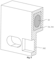
- the seal waterproof layer 34 includes a plastic layer 342 and waterproof glue 341 provided at an inner side of the plastic layer 342, an outer side of the magnetic sensor 33 is wrapped by the waterproof glue 341, the waterproof glue 341 is capable of not only waterproofing the magnetic sensor 33, but also avoiding electric leakage of the magnetic sensor 33, and an outer side of the waterproof glue 341 is provided with the plastic layer 342, so that a waterproof property of the proximity switch 3 is further improved, and the safety of the water tank assembly provided with the proximity switch 3 is further improved.
- an outer side wall of the water tank 1 is provided with an installing column 4 which is configured to form an included angle with a side wall of the water tank 1, the proximity switch 3 is provided with an installing hole 31, the installing column 4 passes through the proximity switch 3 by the installing hole 31 so as to achieve pre-installation of the proximity switch 3, so the installation of the proximity switch 3 is more convenient and rapid by the installing column 4.
- the installing column 4 may have a guiding effect on the pre-installation of the proximity switch 3, so that the pre-installation of the proximity switch 3 is more convenient and rapid.
- the proximity switch 3 is reliably installed on the water tank 1 through thread connection, replaceably, after the proximity switch 3 is pre-installed on the outer side wall of the water tank 1, the proximity switch 3 may also be installed on the outer side wall of the water tank 1 by using at least one mode of welding, binding and locking.
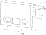
- the outer side wall of the water tank 1 is further provided with a thread column 5, an axis of the thread column 5 is configured perpendicular to the outer side wall of the water tank 1, the thread column 5 is provided with a thread hole 51, the proximity switch 3 is provided with a thread corresponding hole 32 configured corresponding to the thread hole 51 on the thread column 5, as shown in Fig. 3 , after the proximity switch 3 is pre-installed on the outer side wall of the water tank 1, the proximity switch 3 is installed on the outer side wall of the water tank 1 by using a fastener configured in the thread hole 51 on the thread column 5 and the thread corresponding hole 32 on the proximity switch 3, in this way, the installation of the proximity switch 3 is more reliable.
- the side wall of the water tank 1 is provided with a limiting rib 11 used for limiting the proximity switch 3, in an assembling state, there are multiple limiting ribs 11, the multiple limiting ribs 11 are provided at a circumferential outer side of the proximity switch 3, the multiple limiting ribs 11 include multiple limiting ribs provided at an upper part, a lower part and two sides of the proximity switch 3.
- one end of the limiting rib 11 is provided on the outer side wall of the water tank 1, and the other end of the limiting rib 11 is provided with a guiding surface 111.
- the guiding surface 111 is a side surface, towards the proximity switch 3, of the limiting rib 11, along an installing direction of the proximity switch 3, the guiding surface 111 is inclined towards the proximity switch 3, in this way, the guiding surface 111 is used for guiding the proximity switch 3 when the proximity switch 3 is installed on the installing column 4, so that the proximity switch 3 is more conveniently installed on the installing column 4.
- a circumferential outer side of the installing column 4 is provided with a reinforcing rib 41, as shown in Fig. 2 , and the reinforcing rib 41 is formed by the limiting rib 11 connected with the installing column 4, the limiting rib 11 connected with the installing column 4 is connected with the water tank 1 and the installing column 4 at the same time, the reinforcing rib 41 connected with the installing column 4 is capable of not only limiting the proximity switch 3, but also increasing the strength of the installing column 4.
- a circumferential outer side of the thread column 5 on the water tank 1 is provided with the reinforcing rib 41, as shown in Fig. 2 , the reinforcing rib at the outer side of the thread column 5 is formed by the limiting rib 11 connected with the thread column 5, the limiting rib 11 connected with the thread column 5 is connected with the water tank 1 and the thread column 5 at the same time, the reinforcing rib 41 connected with the thread column 5 is capable of not only limiting the proximity switch 3, but also increasing the strength of the thread column 5.
- the proximity switch 3 includes a first lower end portion 35 and a second lower end portion 36, as shown in Fig. 1 , the first lower end portion 35 is provided above the second lower end portion 36, the limiting rib 11 below the installing column 4 includes an avoidance gap 112, the avoidance gap 112 is used for avoiding the second lower end portion 36.
- the guiding surface 11 on the limiting rib 111 configured below the installing column 4 is provided at the avoidance gap 112.
- the water tank assembly further includes a guiding structure 6, as shown in Fig. 1 , the guiding structure is used for guiding the floater 2 when the floater 2 is ascended or descended, in this way, inclination or inclined ascending or descending may not happen when the floater 2 is ascended or descended, and the proximity switch 3 may not be affected to send a signal normally.
- the guiding structure 6 includes a guiding groove 61, as shown in Fig. 1 , the side wall of the water tank 1 forms one side wall of the guiding groove 61, a bottom wall at an inner side of the water tank 1 is provided with a guiding plate 62, the guiding plate 62 is configured to be U-shaped, an U-shaped opening of the guiding plate 62 faces to the side wall, provided with the installing column 4, of the water tank 1, a lower end of the guiding plate 62 is provided on the bottom wall at the inner side of the water tank 1, side walls at two sides of the guiding plate 62 are connected with the inner side wall of the water tank 1, the U-shaped inner side wall of the guiding plate 62 forms an inner side wall of the guiding groove 61, the water tank 1 is communicated with the guiding groove 61, water in the water tank 1 is flowed into the guiding groove 61, a water level in the guiding groove 61 and a water level in the water tank 1 are synchronously changed, the floater 2 is configured
- a limiting structure 63 is provided above the guiding groove 61, as shown in Fig. 1 , the limiting structure is used for limiting an ascended maximum position of the floater 2, in this way, the floater 2 is avoided from being ascended to a distance which may not be sensed by the proximity switch 3, and it is avoided that the proximity switch 3 may not send the first signal correctly, so a risk caused because the water in the water tank 1 is not pumped into the water sink at the upper end of the water curtain in time is avoided.
- the limiting structure 63 includes a blocking plate 631 provided at an upper side of a groove end face of the guiding groove 61, the blocking plate 631 is arranged approximately perpendicular to the side wall of the water tank 1, and the blocking plate 631 is provided on an upper end face of the guiding plate 62.
- the proximity switch 3 is provided at the bottom of the water tank 1, the proximity switch 3 is installed below the guiding structure 6, the proximity switch 3 is located in the disconnecting state when the floater 2 is positioned in a low position, the water in the water tank 1 is stopped to be pumped to the water sink at the upper end of the water curtain, correspondingly, the proximity switch 3 is located in the conducting state when the floater 2 is positioned in a high position, at this moment, the water in the water tank 1 is pumped to the water sink at the upper end of the water curtain.
- a gas treatment device of the disclosure includes the above water tank assembly, capable of avoiding the risk caused by the magnetic sensor 33 contacting the water, and improving the safety of the gas treatment device.
Landscapes
- Engineering & Computer Science (AREA)
- Chemical & Material Sciences (AREA)
- Combustion & Propulsion (AREA)
- Mechanical Engineering (AREA)
- General Engineering & Computer Science (AREA)
- Physics & Mathematics (AREA)
- Fluid Mechanics (AREA)
- General Physics & Mathematics (AREA)
- Life Sciences & Earth Sciences (AREA)
- Sustainable Development (AREA)
- Level Indicators Using A Float (AREA)
Claims (11)
- Wassertankanordnung, umfassend einen Wassertank (1), einen Schwimmer (2) und einen Näherungsschalter (3), wobei der Schwimmer (2) mit dem Wasser in dem Wassertank (1) auf- oder absteigen kann, wobei der Schwimmer (2) magnetische Eigenschaften aufweist, wobei der Näherungsschalter (3) einen Magnetsensor (33) und eine wasserdichte Schicht (34), die außerhalb des Magnetsensors (33) bereitgestellt wird, umfasst, wobei der Magnetsensor (33) gemäß verschiedenen Positionen des Schwimmers (2) im Verhältnis zu dem Magnetsensor (33) unterschiedliche Signale ausgibt, und die wasserdichte Schicht (34) verwendet wird, um den Magnetsensor (33) wasserdicht zu machen,
dadurch gekennzeichnet, dass eine Außenseitenwand des Wassertanks (1) mit einer Installationssäule (4) versehen ist, die dazu konfiguriert ist, einen eingeschlossenen Winkel mit einer Seitenwand des Wassertanks (1) zu bilden, und die Installationssäule (4) durch den Näherungsschalter (3) geht, um eine Vorinstallation des Näherungsschalters (3) zu erreichen, wobei die Seitenwand des Wassertanks (1) mit mehreren Begrenzungsrippen (11) versehen ist, wobei die mehreren Begrenzungsrippen (11) auf einer äußeren Umfangsseite des Näherungsschalters (3) bereitgestellt werden, wobei die mehreren Begrenzungsrippen (11) an einem oberen Teil, einem unteren Teil und auf beiden Seiten des Näherungsschalters (3) bereitgestellt werden. - Wassertankanordnung nach Anspruch 1, wobei die wasserdichte Schicht (34) eine Kunststoffschicht (342) und einen wasserdichten Klebstoff (341), der auf einer inneren Seite der Kunststoffschicht (342) bereitgestellt wird, umfasst.
- Wassertankanordnung nach Anspruch 1, wobei ein Ende der Begrenzungsrippe (11) auf der äußeren Seitenwand des Wassertanks (1) bereitgestellt wird, und das andere Ende der Begrenzungsrippe (11) mit einer Führungsfläche versehen ist, die zum Führen verwendet wird, wenn der Näherungsschalter (3) an der Installationssäule (4) installiert ist.
- Wassertankanordnung nach Anspruch 1, wobei eine äußere Umfangsseite der Installationssäule (4) mit einer Verstärkungsrippe (41) versehen ist, und die Verstärkungsrippe (41) durch die Begrenzungsrippe (11), die mit der Installationssäule (4) verbunden ist, gebildet ist.
- Wassertankanordnung nach Anspruch 1, wobei der Näherungsschalter (3), der an der Installationssäule (4) vorinstalliert ist, mit dem Wassertank (1) über mindestens eine Möglichkeit von einer Schraubverbindung, Schweißung, Bindung und Verriegelung verbunden ist.
- Wassertankanordnung nach Anspruch 1, wobei die Wassertankanordnung (1) ferner eine Führungsstruktur (6) umfasst, die verwendet wird, um den Schwimmer (2) zu führen, wenn der Schwimmer (2) angehoben oder abgesenkt wird.
- Wassertankanordnung nach Anspruch 6, wobei die Führungsstruktur (6) eine Führungsnut (61) umfasst, wobei die Seitenwand des Wassertanks (1) eine Seitenwand der Führungsnut (61) bildet.
- Wassertankanordnung nach Anspruch 7, wobei eine Begrenzungsstruktur (63) oberhalb der Führungsnut (61) bereitgestellt wird, und verwendet wird, um eine maximale angehobene Position des Schwimmers (2) zu begrenzen.
- Wassertankanordnung nach Anspruch 8, wobei die Begrenzungsstruktur (63) eine Blockierplatte (631) umfasst, die auf einer oberen Seite einer Nutenendseite der Führungsnut (61) bereitgestellt wird, wobei die Blockierplatte (631) rechtwinklig zu der Seitenwand des Wassertanks (1) angeordnet ist.
- Gasbehandlungsvorrichtung, umfassend die Wassertankanordnung nach einem der Ansprüche 1 bis 9.
- Gasbehandlungsvorrichtung nach Anspruch 10, wobei die Gasbehandlungsvorrichtung ein Kühlgebläse umfasst.
Applications Claiming Priority (2)
| Application Number | Priority Date | Filing Date | Title |
|---|---|---|---|
| CN201810999641.0A CN109386921B (zh) | 2018-08-30 | 2018-08-30 | 水箱组件和气体处理设备 |
| PCT/CN2018/122495 WO2020042460A1 (zh) | 2018-08-30 | 2018-12-21 | 水箱组件和气体处理设备 |
Publications (3)
| Publication Number | Publication Date |
|---|---|
| EP3816592A1 EP3816592A1 (de) | 2021-05-05 |
| EP3816592A4 EP3816592A4 (de) | 2022-01-19 |
| EP3816592B1 true EP3816592B1 (de) | 2023-03-29 |
Family
ID=65417680
Family Applications (1)
| Application Number | Title | Priority Date | Filing Date |
|---|---|---|---|
| EP18931508.8A Active EP3816592B1 (de) | 2018-08-30 | 2018-12-21 | Wassertankanordnung und gasbehandlungsvorrichtung |
Country Status (3)
| Country | Link |
|---|---|
| EP (1) | EP3816592B1 (de) |
| CN (1) | CN109386921B (de) |
| WO (1) | WO2020042460A1 (de) |
Citations (1)
| Publication number | Priority date | Publication date | Assignee | Title |
|---|---|---|---|---|
| CN205679301U (zh) * | 2016-05-26 | 2016-11-09 | 广东美的制冷设备有限公司 | 水位控制装置及具有该水位控制装置的电器设备 |
Family Cites Families (9)
| Publication number | Priority date | Publication date | Assignee | Title |
|---|---|---|---|---|
| DE3843979A1 (de) * | 1988-12-27 | 1990-06-28 | Waldemar Sperling | Sparvorrichtung zur bemessung der in eine badewanne einzufuellenden wassermenge, mit automatischer wasserzufuhrabschaltung |
| JP2886450B2 (ja) * | 1994-05-06 | 1999-04-26 | 株式会社ニシヤマ | フロートスイッチ |
| JP4365306B2 (ja) * | 2004-11-12 | 2009-11-18 | 株式会社パイオラックス | フューエルゲージ取付け構造 |
| JP5678865B2 (ja) * | 2011-10-28 | 2015-03-04 | 株式会社デンソー | 液面検出装置の取付構造 |
| JP6156040B2 (ja) * | 2013-10-07 | 2017-07-05 | 株式会社デンソー | 液面検出装置 |
| CN106153156A (zh) * | 2015-03-29 | 2016-11-23 | 重庆牧笛科技有限责任公司 | 具有良好防水效果的液位传感器 |
| CN205939492U (zh) * | 2016-07-29 | 2017-02-08 | 广东美的环境电器制造有限公司 | 冷风扇 |
| GB2561530B (en) * | 2017-01-20 | 2022-01-12 | Bamford Excavators Ltd | A fuel filter |
| CN108253562B (zh) * | 2017-12-26 | 2020-05-26 | 漳州蒙发利实业有限公司 | 一种紧凑型冷风扇 |
-
2018
- 2018-08-30 CN CN201810999641.0A patent/CN109386921B/zh active Active
- 2018-12-21 WO PCT/CN2018/122495 patent/WO2020042460A1/zh not_active Ceased
- 2018-12-21 EP EP18931508.8A patent/EP3816592B1/de active Active
Patent Citations (1)
| Publication number | Priority date | Publication date | Assignee | Title |
|---|---|---|---|---|
| CN205679301U (zh) * | 2016-05-26 | 2016-11-09 | 广东美的制冷设备有限公司 | 水位控制装置及具有该水位控制装置的电器设备 |
Also Published As
| Publication number | Publication date |
|---|---|
| WO2020042460A1 (zh) | 2020-03-05 |
| EP3816592A1 (de) | 2021-05-05 |
| EP3816592A4 (de) | 2022-01-19 |
| CN109386921B (zh) | 2020-01-10 |
| CN109386921A (zh) | 2019-02-26 |
Similar Documents
| Publication | Publication Date | Title |
|---|---|---|
| US5014909A (en) | Television receiver | |
| US20020124582A1 (en) | Condensate overflow safety switch | |
| US6374854B1 (en) | Device for preventing permanent entrapment | |
| EP2949934B1 (de) | Verdichterschallisolierungsstruktur und mit dem verdichter, der diese aufweist, versehene klimaanlage | |
| KR102658109B1 (ko) | 가습기 | |
| EP3816592B1 (de) | Wassertankanordnung und gasbehandlungsvorrichtung | |
| EP1510765B1 (de) | Verbesserungen an oder bei Pumpen | |
| KR20090094550A (ko) | 공기조화기 실내기의 드레인장치 | |
| CN101418965B (zh) | 空调机的室内机 | |
| AU2024346471A1 (en) | Base plate and integral air-source heat pump water heater | |
| CN220339150U (zh) | 冷凝水排水装置及具有其的采暖炉 | |
| KR102308260B1 (ko) | 전선관내 결로발생의 방지 및 기밀유지용 차단캡 | |
| US20150343880A1 (en) | Pressure decoupling of air intake drainage and drainage of main housing | |
| JP2014184882A (ja) | 車両用液体加熱装置 | |
| JP5470419B2 (ja) | 空気調和機の室内機 | |
| CN223360769U (zh) | 空调机组及空调系统 | |
| CN220911565U (zh) | 空气处理机组 | |
| US20090197519A1 (en) | Radon vent fan system | |
| CN219390055U (zh) | 接水盘和具有其的空调器 | |
| US20090242004A1 (en) | Dishwasher | |
| CN223536567U (zh) | 新型排水泵及排水设备 | |
| CN214472556U (zh) | 一种信号接插件 | |
| CN119268020A (zh) | 空调机组及空调系统 | |
| JP2578192Y2 (ja) | 給水装置における電気装置収納ケースの防水・防湿構造 | |
| CN109403435A (zh) | 一种下水器 |
Legal Events
| Date | Code | Title | Description |
|---|---|---|---|
| STAA | Information on the status of an ep patent application or granted ep patent |
Free format text: STATUS: THE INTERNATIONAL PUBLICATION HAS BEEN MADE |
|
| PUAI | Public reference made under article 153(3) epc to a published international application that has entered the european phase |
Free format text: ORIGINAL CODE: 0009012 |
|
| STAA | Information on the status of an ep patent application or granted ep patent |
Free format text: STATUS: REQUEST FOR EXAMINATION WAS MADE |
|
| 17P | Request for examination filed |
Effective date: 20201217 |
|
| AK | Designated contracting states |
Kind code of ref document: A1 Designated state(s): AL AT BE BG CH CY CZ DE DK EE ES FI FR GB GR HR HU IE IS IT LI LT LU LV MC MK MT NL NO PL PT RO RS SE SI SK SM TR |
|
| DAV | Request for validation of the european patent (deleted) | ||
| DAX | Request for extension of the european patent (deleted) | ||
| A4 | Supplementary search report drawn up and despatched |
Effective date: 20211216 |
|
| RIC1 | Information provided on ipc code assigned before grant |
Ipc: G01F 23/76 20060101ALN20211210BHEP Ipc: G01F 23/00 20060101ALI20211210BHEP Ipc: G01F 23/74 20060101AFI20211210BHEP |
|
| STAA | Information on the status of an ep patent application or granted ep patent |
Free format text: STATUS: EXAMINATION IS IN PROGRESS |
|
| 17Q | First examination report despatched |
Effective date: 20220708 |
|
| GRAP | Despatch of communication of intention to grant a patent |
Free format text: ORIGINAL CODE: EPIDOSNIGR1 |
|
| STAA | Information on the status of an ep patent application or granted ep patent |
Free format text: STATUS: GRANT OF PATENT IS INTENDED |
|
| RIC1 | Information provided on ipc code assigned before grant |
Ipc: G01F 23/76 20060101ALN20220928BHEP Ipc: G01F 23/00 20060101ALI20220928BHEP Ipc: G01F 23/74 20060101AFI20220928BHEP |
|
| RIC1 | Information provided on ipc code assigned before grant |
Ipc: G01F 23/76 20060101ALN20221011BHEP Ipc: G01F 23/00 20060101ALI20221011BHEP Ipc: G01F 23/74 20060101AFI20221011BHEP |
|
| INTG | Intention to grant announced |
Effective date: 20221102 |
|
| GRAS | Grant fee paid |
Free format text: ORIGINAL CODE: EPIDOSNIGR3 |
|
| GRAA | (expected) grant |
Free format text: ORIGINAL CODE: 0009210 |
|
| STAA | Information on the status of an ep patent application or granted ep patent |
Free format text: STATUS: THE PATENT HAS BEEN GRANTED |
|
| AK | Designated contracting states |
Kind code of ref document: B1 Designated state(s): AL AT BE BG CH CY CZ DE DK EE ES FI FR GB GR HR HU IE IS IT LI LT LU LV MC MK MT NL NO PL PT RO RS SE SI SK SM TR |
|
| REG | Reference to a national code |
Ref country code: CH Ref legal event code: EP |
|
| REG | Reference to a national code |
Ref country code: DE Ref legal event code: R096 Ref document number: 602018047931 Country of ref document: DE |
|
| REG | Reference to a national code |
Ref country code: AT Ref legal event code: REF Ref document number: 1556991 Country of ref document: AT Kind code of ref document: T Effective date: 20230415 |
|
| REG | Reference to a national code |
Ref country code: IE Ref legal event code: FG4D |
|
| REG | Reference to a national code |
Ref country code: LT Ref legal event code: MG9D |
|
| P01 | Opt-out of the competence of the unified patent court (upc) registered |
Effective date: 20230530 |
|
| PG25 | Lapsed in a contracting state [announced via postgrant information from national office to epo] |
Ref country code: RS Free format text: LAPSE BECAUSE OF FAILURE TO SUBMIT A TRANSLATION OF THE DESCRIPTION OR TO PAY THE FEE WITHIN THE PRESCRIBED TIME-LIMIT Effective date: 20230329 Ref country code: NO Free format text: LAPSE BECAUSE OF FAILURE TO SUBMIT A TRANSLATION OF THE DESCRIPTION OR TO PAY THE FEE WITHIN THE PRESCRIBED TIME-LIMIT Effective date: 20230629 Ref country code: LV Free format text: LAPSE BECAUSE OF FAILURE TO SUBMIT A TRANSLATION OF THE DESCRIPTION OR TO PAY THE FEE WITHIN THE PRESCRIBED TIME-LIMIT Effective date: 20230329 Ref country code: LT Free format text: LAPSE BECAUSE OF FAILURE TO SUBMIT A TRANSLATION OF THE DESCRIPTION OR TO PAY THE FEE WITHIN THE PRESCRIBED TIME-LIMIT Effective date: 20230329 Ref country code: HR Free format text: LAPSE BECAUSE OF FAILURE TO SUBMIT A TRANSLATION OF THE DESCRIPTION OR TO PAY THE FEE WITHIN THE PRESCRIBED TIME-LIMIT Effective date: 20230329 |
|
| REG | Reference to a national code |
Ref country code: NL Ref legal event code: MP Effective date: 20230329 |
|
| REG | Reference to a national code |
Ref country code: AT Ref legal event code: MK05 Ref document number: 1556991 Country of ref document: AT Kind code of ref document: T Effective date: 20230329 |
|
| PG25 | Lapsed in a contracting state [announced via postgrant information from national office to epo] |
Ref country code: SE Free format text: LAPSE BECAUSE OF FAILURE TO SUBMIT A TRANSLATION OF THE DESCRIPTION OR TO PAY THE FEE WITHIN THE PRESCRIBED TIME-LIMIT Effective date: 20230329 Ref country code: NL Free format text: LAPSE BECAUSE OF FAILURE TO SUBMIT A TRANSLATION OF THE DESCRIPTION OR TO PAY THE FEE WITHIN THE PRESCRIBED TIME-LIMIT Effective date: 20230329 Ref country code: GR Free format text: LAPSE BECAUSE OF FAILURE TO SUBMIT A TRANSLATION OF THE DESCRIPTION OR TO PAY THE FEE WITHIN THE PRESCRIBED TIME-LIMIT Effective date: 20230630 Ref country code: FI Free format text: LAPSE BECAUSE OF FAILURE TO SUBMIT A TRANSLATION OF THE DESCRIPTION OR TO PAY THE FEE WITHIN THE PRESCRIBED TIME-LIMIT Effective date: 20230329 |
|
| PG25 | Lapsed in a contracting state [announced via postgrant information from national office to epo] |
Ref country code: SM Free format text: LAPSE BECAUSE OF FAILURE TO SUBMIT A TRANSLATION OF THE DESCRIPTION OR TO PAY THE FEE WITHIN THE PRESCRIBED TIME-LIMIT Effective date: 20230329 Ref country code: RO Free format text: LAPSE BECAUSE OF FAILURE TO SUBMIT A TRANSLATION OF THE DESCRIPTION OR TO PAY THE FEE WITHIN THE PRESCRIBED TIME-LIMIT Effective date: 20230329 Ref country code: PT Free format text: LAPSE BECAUSE OF FAILURE TO SUBMIT A TRANSLATION OF THE DESCRIPTION OR TO PAY THE FEE WITHIN THE PRESCRIBED TIME-LIMIT Effective date: 20230731 Ref country code: ES Free format text: LAPSE BECAUSE OF FAILURE TO SUBMIT A TRANSLATION OF THE DESCRIPTION OR TO PAY THE FEE WITHIN THE PRESCRIBED TIME-LIMIT Effective date: 20230329 Ref country code: EE Free format text: LAPSE BECAUSE OF FAILURE TO SUBMIT A TRANSLATION OF THE DESCRIPTION OR TO PAY THE FEE WITHIN THE PRESCRIBED TIME-LIMIT Effective date: 20230329 Ref country code: AT Free format text: LAPSE BECAUSE OF FAILURE TO SUBMIT A TRANSLATION OF THE DESCRIPTION OR TO PAY THE FEE WITHIN THE PRESCRIBED TIME-LIMIT Effective date: 20230329 |
|
| PG25 | Lapsed in a contracting state [announced via postgrant information from national office to epo] |
Ref country code: SK Free format text: LAPSE BECAUSE OF FAILURE TO SUBMIT A TRANSLATION OF THE DESCRIPTION OR TO PAY THE FEE WITHIN THE PRESCRIBED TIME-LIMIT Effective date: 20230329 Ref country code: PL Free format text: LAPSE BECAUSE OF FAILURE TO SUBMIT A TRANSLATION OF THE DESCRIPTION OR TO PAY THE FEE WITHIN THE PRESCRIBED TIME-LIMIT Effective date: 20230329 Ref country code: IS Free format text: LAPSE BECAUSE OF FAILURE TO SUBMIT A TRANSLATION OF THE DESCRIPTION OR TO PAY THE FEE WITHIN THE PRESCRIBED TIME-LIMIT Effective date: 20230729 |
|
| REG | Reference to a national code |
Ref country code: DE Ref legal event code: R097 Ref document number: 602018047931 Country of ref document: DE |
|
| PG25 | Lapsed in a contracting state [announced via postgrant information from national office to epo] |
Ref country code: DK Free format text: LAPSE BECAUSE OF FAILURE TO SUBMIT A TRANSLATION OF THE DESCRIPTION OR TO PAY THE FEE WITHIN THE PRESCRIBED TIME-LIMIT Effective date: 20230329 Ref country code: CZ Free format text: LAPSE BECAUSE OF FAILURE TO SUBMIT A TRANSLATION OF THE DESCRIPTION OR TO PAY THE FEE WITHIN THE PRESCRIBED TIME-LIMIT Effective date: 20230329 |
|
| PLBE | No opposition filed within time limit |
Free format text: ORIGINAL CODE: 0009261 |
|
| STAA | Information on the status of an ep patent application or granted ep patent |
Free format text: STATUS: NO OPPOSITION FILED WITHIN TIME LIMIT |
|
| 26N | No opposition filed |
Effective date: 20240103 |
|
| PG25 | Lapsed in a contracting state [announced via postgrant information from national office to epo] |
Ref country code: SI Free format text: LAPSE BECAUSE OF FAILURE TO SUBMIT A TRANSLATION OF THE DESCRIPTION OR TO PAY THE FEE WITHIN THE PRESCRIBED TIME-LIMIT Effective date: 20230329 |
|
| PG25 | Lapsed in a contracting state [announced via postgrant information from national office to epo] |
Ref country code: SI Free format text: LAPSE BECAUSE OF FAILURE TO SUBMIT A TRANSLATION OF THE DESCRIPTION OR TO PAY THE FEE WITHIN THE PRESCRIBED TIME-LIMIT Effective date: 20230329 Ref country code: IT Free format text: LAPSE BECAUSE OF FAILURE TO SUBMIT A TRANSLATION OF THE DESCRIPTION OR TO PAY THE FEE WITHIN THE PRESCRIBED TIME-LIMIT Effective date: 20230329 |
|
| REG | Reference to a national code |
Ref country code: CH Ref legal event code: PL |
|
| PG25 | Lapsed in a contracting state [announced via postgrant information from national office to epo] |
Ref country code: LU Free format text: LAPSE BECAUSE OF NON-PAYMENT OF DUE FEES Effective date: 20231221 |
|
| PG25 | Lapsed in a contracting state [announced via postgrant information from national office to epo] |
Ref country code: MC Free format text: LAPSE BECAUSE OF FAILURE TO SUBMIT A TRANSLATION OF THE DESCRIPTION OR TO PAY THE FEE WITHIN THE PRESCRIBED TIME-LIMIT Effective date: 20230329 |
|
| GBPC | Gb: european patent ceased through non-payment of renewal fee |
Effective date: 20231221 |
|
| REG | Reference to a national code |
Ref country code: BE Ref legal event code: MM Effective date: 20231231 |
|
| PG25 | Lapsed in a contracting state [announced via postgrant information from national office to epo] |
Ref country code: MC Free format text: LAPSE BECAUSE OF FAILURE TO SUBMIT A TRANSLATION OF THE DESCRIPTION OR TO PAY THE FEE WITHIN THE PRESCRIBED TIME-LIMIT Effective date: 20230329 Ref country code: LU Free format text: LAPSE BECAUSE OF NON-PAYMENT OF DUE FEES Effective date: 20231221 |
|
| REG | Reference to a national code |
Ref country code: IE Ref legal event code: MM4A |
|
| PG25 | Lapsed in a contracting state [announced via postgrant information from national office to epo] |
Ref country code: IE Free format text: LAPSE BECAUSE OF NON-PAYMENT OF DUE FEES Effective date: 20231221 |
|
| PG25 | Lapsed in a contracting state [announced via postgrant information from national office to epo] |
Ref country code: GB Free format text: LAPSE BECAUSE OF NON-PAYMENT OF DUE FEES Effective date: 20231221 |
|
| PG25 | Lapsed in a contracting state [announced via postgrant information from national office to epo] |
Ref country code: BE Free format text: LAPSE BECAUSE OF NON-PAYMENT OF DUE FEES Effective date: 20231231 |
|
| PG25 | Lapsed in a contracting state [announced via postgrant information from national office to epo] |
Ref country code: FR Free format text: LAPSE BECAUSE OF NON-PAYMENT OF DUE FEES Effective date: 20231231 |
|
| PG25 | Lapsed in a contracting state [announced via postgrant information from national office to epo] |
Ref country code: CH Free format text: LAPSE BECAUSE OF NON-PAYMENT OF DUE FEES Effective date: 20231231 |
|
| PG25 | Lapsed in a contracting state [announced via postgrant information from national office to epo] |
Ref country code: IE Free format text: LAPSE BECAUSE OF NON-PAYMENT OF DUE FEES Effective date: 20231221 Ref country code: GB Free format text: LAPSE BECAUSE OF NON-PAYMENT OF DUE FEES Effective date: 20231221 Ref country code: FR Free format text: LAPSE BECAUSE OF NON-PAYMENT OF DUE FEES Effective date: 20231231 Ref country code: CH Free format text: LAPSE BECAUSE OF NON-PAYMENT OF DUE FEES Effective date: 20231231 Ref country code: BE Free format text: LAPSE BECAUSE OF NON-PAYMENT OF DUE FEES Effective date: 20231231 |
|
| PG25 | Lapsed in a contracting state [announced via postgrant information from national office to epo] |
Ref country code: BG Free format text: LAPSE BECAUSE OF FAILURE TO SUBMIT A TRANSLATION OF THE DESCRIPTION OR TO PAY THE FEE WITHIN THE PRESCRIBED TIME-LIMIT Effective date: 20230329 |
|
| PG25 | Lapsed in a contracting state [announced via postgrant information from national office to epo] |
Ref country code: BG Free format text: LAPSE BECAUSE OF FAILURE TO SUBMIT A TRANSLATION OF THE DESCRIPTION OR TO PAY THE FEE WITHIN THE PRESCRIBED TIME-LIMIT Effective date: 20230329 |
|
| PG25 | Lapsed in a contracting state [announced via postgrant information from national office to epo] |
Ref country code: CY Free format text: LAPSE BECAUSE OF FAILURE TO SUBMIT A TRANSLATION OF THE DESCRIPTION OR TO PAY THE FEE WITHIN THE PRESCRIBED TIME-LIMIT; INVALID AB INITIO Effective date: 20181221 |
|
| PG25 | Lapsed in a contracting state [announced via postgrant information from national office to epo] |
Ref country code: HU Free format text: LAPSE BECAUSE OF FAILURE TO SUBMIT A TRANSLATION OF THE DESCRIPTION OR TO PAY THE FEE WITHIN THE PRESCRIBED TIME-LIMIT; INVALID AB INITIO Effective date: 20181221 |
|
| PG25 | Lapsed in a contracting state [announced via postgrant information from national office to epo] |
Ref country code: TR Free format text: LAPSE BECAUSE OF FAILURE TO SUBMIT A TRANSLATION OF THE DESCRIPTION OR TO PAY THE FEE WITHIN THE PRESCRIBED TIME-LIMIT Effective date: 20230329 |
|
| PGFP | Annual fee paid to national office [announced via postgrant information from national office to epo] |
Ref country code: DE Payment date: 20251222 Year of fee payment: 8 |