EP3816479B1 - Planetenrollengewindetrieb für eine schlupffreie teleskopspindel - Google Patents
Planetenrollengewindetrieb für eine schlupffreie teleskopspindel Download PDFInfo
- Publication number
- EP3816479B1 EP3816479B1 EP19206020.0A EP19206020A EP3816479B1 EP 3816479 B1 EP3816479 B1 EP 3816479B1 EP 19206020 A EP19206020 A EP 19206020A EP 3816479 B1 EP3816479 B1 EP 3816479B1
- Authority
- EP
- European Patent Office
- Prior art keywords
- spindle
- male thread
- external toothing
- roller screw
- planetary
- Prior art date
- Legal status (The legal status is an assumption and is not a legal conclusion. Google has not performed a legal analysis and makes no representation as to the accuracy of the status listed.)
- Active
Links
Images



Classifications
-
- F—MECHANICAL ENGINEERING; LIGHTING; HEATING; WEAPONS; BLASTING
- F16—ENGINEERING ELEMENTS AND UNITS; GENERAL MEASURES FOR PRODUCING AND MAINTAINING EFFECTIVE FUNCTIONING OF MACHINES OR INSTALLATIONS; THERMAL INSULATION IN GENERAL
- F16H—GEARING
- F16H25/00—Gearings comprising primarily only cams, cam-followers and screw-and-nut mechanisms
- F16H25/18—Gearings comprising primarily only cams, cam-followers and screw-and-nut mechanisms for conveying or interconverting oscillating or reciprocating motions
- F16H25/20—Screw mechanisms
- F16H25/22—Screw mechanisms with balls, rollers, or similar members between the co-operating parts; Elements essential to the use of such members
- F16H25/2247—Screw mechanisms with balls, rollers, or similar members between the co-operating parts; Elements essential to the use of such members with rollers
- F16H25/2252—Planetary rollers between nut and screw
-
- F—MECHANICAL ENGINEERING; LIGHTING; HEATING; WEAPONS; BLASTING
- F16—ENGINEERING ELEMENTS AND UNITS; GENERAL MEASURES FOR PRODUCING AND MAINTAINING EFFECTIVE FUNCTIONING OF MACHINES OR INSTALLATIONS; THERMAL INSULATION IN GENERAL
- F16H—GEARING
- F16H25/00—Gearings comprising primarily only cams, cam-followers and screw-and-nut mechanisms
- F16H25/18—Gearings comprising primarily only cams, cam-followers and screw-and-nut mechanisms for conveying or interconverting oscillating or reciprocating motions
- F16H25/20—Screw mechanisms
- F16H25/2056—Telescopic screws with at least three screw members in coaxial arrangement
-
- A—HUMAN NECESSITIES
- A61—MEDICAL OR VETERINARY SCIENCE; HYGIENE
- A61B—DIAGNOSIS; SURGERY; IDENTIFICATION
- A61B5/00—Measuring for diagnostic purposes; Identification of persons
- A61B5/145—Measuring characteristics of blood in vivo, e.g. gas concentration or pH-value ; Measuring characteristics of body fluids or tissues, e.g. interstitial fluid or cerebral tissue
- A61B5/14532—Measuring characteristics of blood in vivo, e.g. gas concentration or pH-value ; Measuring characteristics of body fluids or tissues, e.g. interstitial fluid or cerebral tissue for measuring glucose, e.g. by tissue impedance measurement
-
- A—HUMAN NECESSITIES
- A61—MEDICAL OR VETERINARY SCIENCE; HYGIENE
- A61M—DEVICES FOR INTRODUCING MEDIA INTO, OR ONTO, THE BODY; DEVICES FOR TRANSDUCING BODY MEDIA OR FOR TAKING MEDIA FROM THE BODY; DEVICES FOR PRODUCING OR ENDING SLEEP OR STUPOR
- A61M5/00—Devices for bringing media into the body in a subcutaneous, intra-vascular or intramuscular way; Accessories therefor, e.g. filling or cleaning devices, arm-rests
- A61M5/178—Syringes
- A61M5/31—Details
- A61M5/315—Pistons; Piston-rods; Guiding, blocking or restricting the movement of the rod or piston; Appliances on the rod for facilitating dosing ; Dosing mechanisms
- A61M5/31511—Piston or piston-rod constructions, e.g. connection of piston with piston-rod
- A61M2005/3152—Piston or piston-rod constructions, e.g. connection of piston with piston-rod including gearings to multiply or attenuate the piston displacing force
-
- A—HUMAN NECESSITIES
- A61—MEDICAL OR VETERINARY SCIENCE; HYGIENE
- A61M—DEVICES FOR INTRODUCING MEDIA INTO, OR ONTO, THE BODY; DEVICES FOR TRANSDUCING BODY MEDIA OR FOR TAKING MEDIA FROM THE BODY; DEVICES FOR PRODUCING OR ENDING SLEEP OR STUPOR
- A61M5/00—Devices for bringing media into the body in a subcutaneous, intra-vascular or intramuscular way; Accessories therefor, e.g. filling or cleaning devices, arm-rests
- A61M5/14—Infusion devices, e.g. infusing by gravity; Blood infusion; Accessories therefor
- A61M5/142—Pressure infusion, e.g. using pumps
- A61M5/14244—Pressure infusion, e.g. using pumps adapted to be carried by the patient, e.g. portable on the body
-
- A—HUMAN NECESSITIES
- A61—MEDICAL OR VETERINARY SCIENCE; HYGIENE
- A61M—DEVICES FOR INTRODUCING MEDIA INTO, OR ONTO, THE BODY; DEVICES FOR TRANSDUCING BODY MEDIA OR FOR TAKING MEDIA FROM THE BODY; DEVICES FOR PRODUCING OR ENDING SLEEP OR STUPOR
- A61M5/00—Devices for bringing media into the body in a subcutaneous, intra-vascular or intramuscular way; Accessories therefor, e.g. filling or cleaning devices, arm-rests
- A61M5/14—Infusion devices, e.g. infusing by gravity; Blood infusion; Accessories therefor
- A61M5/142—Pressure infusion, e.g. using pumps
- A61M5/145—Pressure infusion, e.g. using pumps using pressurised reservoirs, e.g. pressurised by means of pistons
- A61M5/1452—Pressure infusion, e.g. using pumps using pressurised reservoirs, e.g. pressurised by means of pistons pressurised by means of pistons
- A61M5/14566—Pressure infusion, e.g. using pumps using pressurised reservoirs, e.g. pressurised by means of pistons pressurised by means of pistons with a replaceable reservoir for receiving a piston rod of the pump
-
- A—HUMAN NECESSITIES
- A61—MEDICAL OR VETERINARY SCIENCE; HYGIENE
- A61M—DEVICES FOR INTRODUCING MEDIA INTO, OR ONTO, THE BODY; DEVICES FOR TRANSDUCING BODY MEDIA OR FOR TAKING MEDIA FROM THE BODY; DEVICES FOR PRODUCING OR ENDING SLEEP OR STUPOR
- A61M5/00—Devices for bringing media into the body in a subcutaneous, intra-vascular or intramuscular way; Accessories therefor, e.g. filling or cleaning devices, arm-rests
- A61M5/14—Infusion devices, e.g. infusing by gravity; Blood infusion; Accessories therefor
- A61M5/168—Means for controlling media flow to the body or for metering media to the body, e.g. drip meters, counters ; Monitoring media flow to the body
- A61M5/172—Means for controlling media flow to the body or for metering media to the body, e.g. drip meters, counters ; Monitoring media flow to the body electrical or electronic
Definitions
- the present invention relates to a planetary roller screw according to the preamble of independent claim 1.
- planetary roller screw drives which are suitable as telescopic spindles, a set of planetary rollers rolls on the one hand on a central spindle and on the other hand on an internal thread of a ring gear sleeve. Due to the different speeds of the spindle, the planetary rollers and the ring gear sleeve, which depend on the diameter ratios, there are pitch differences that produce the desired synchronous lifting movement.
- the central spindle has the same number of threads as the planetary rollers, but has a smaller diameter than the planetary rollers.
- the thread of the ring gear sleeve usually has twice the number of threads as the planetary rollers.
- the rolling movement of the planetary rollers is associated with slippage, which is not constant but depends on the load. If the telescopic spindle is to be used as an actuator, the slip leads to inaccuracies in positioning.
- Planetary roller screws for example, are out DE 102015218621 A1 and EP 1 918 612 A1 known. From DE 102015218621 A1 and EP 1 918 612 A1
- known planetary roller screw drives are not suitable for a telescopic spindle, since a relative axial displacement between the spindle and the planetary rollers is not possible.
- a planetary roller screw of the generic type is, for example, from DE 10 2017 126570 A1 known.
- This generic planetary roller screw drive has a spindle with an external thread, a nut with an internal thread, and planetary rollers that are arranged between the spindle and the nut and each have an external thread that connects both to the external thread of the spindle and to the internal thread of the nut is engaged, with both the spindle and the planetary rollers also each having external teeth, and with the external teeth of the spindle meshing with the external teeth of the planetary rollers, with the external teeth of the spindle meshing with the external thread of the spindle and/or the external teeth of the planetary rollers meshing with the external thread of the planetary rollers are introduced, so that the spindle and/or planetary rollers have an overlapping section in which the respective external thread and the respective external toothing are superimposed, such that a relative axial displacement between the spindle and the planetary rollers is possible, the planetary roller screw drive also
- the object of the present invention is to specify a planetary roller screw drive which is suitable for a telescopic spindle and in which the slip referred to above is reduced.
- the object is achieved by the features of independent claim 1. Accordingly, in a planetary roller screw according to the preamble of independent claim 1, the object is achieved according to the invention if the planetary roller screw has a housing on which the spindle is rotatably mounted, the ring gear is non-rotatable and axially displaceable in relation to the housing, with the nut also being mounted in an axially displaceable manner in relation to the ring gear, and with the diameter ratios between the spindle, planetary rollers and nut being selected in such a way that when the spindle rotates, both a relative axial displacement of the ring gear in relation to the housing as well as a relative axial displacement of the nut in relation to the ring gear.
- the planetary roller screw can be used as a compact telescopic spindle.
- the engagement of the external teeth of the spindle and the planetary rollers prevents slippage between the spindle and the planetary rollers.
- the speeds of the components involved are also determined by the teeth.
- the solution according to the invention also allows a compact design.
- Spindle and nut are preferably arranged coaxially. More preferably, the planetary rollers all have the same outside diameter. Three planetary rollers are particularly preferred, since a stroke ratio of 1:2 is established in this embodiment. Alternatively, four or more planetary rollers can also be provided. Further advantageous embodiments of the present invention are the subject matter of the dependent claims.
- either the external toothing of the spindle is introduced into the external thread of the spindle, the external toothing of the planetary rollers being located in a section existing axially outside the external thread of the planetary rollers, or the external toothing of the planetary rollers introduced into the external thread of the planetary rollers, the external toothing of the spindle being located in a section axially outside the external thread of the spindle.
- This embodiment can be produced easily and reduces the production costs.
- the component, in which the external toothing and the external thread do not overlap, can have a simple threaded section with a pinion which is easy to manufacture and is axially connected thereto.
- the external toothing of the spindle is preferably introduced into the external thread of the spindle, with the external toothing and external thread of the planetary rollers not overlapping. This embodiment is particularly easy to manufacture.
- the external toothing of the planetary rollers is introduced into the external thread of the planetary rollers, with the external toothing of the spindle being located in a section that is axially outside of the external thread of the spindle.
- the external toothing of the spindle is present axially both before and after the external thread of the spindle.
- the external toothing of the spindle is formed by two pinions between which the external thread of the spindle extends.
- one of the two pinions is located approximately in the center of the spindle, with the other of the two pinions being located at the distal end of the spindle.
- approximately in the middle of the spindle means in a range between 35% and 65% of the total length of the spindle, preferably in a range between 40% and 60% of the total length of the spindle.
- the distal end is understood to mean that end which is at the front in the direction in which the planetary roller screw drive is extended. The proximal end of the spindle is therefore the opposite end, which points to the fixed end of the planetary roller screw.
- a proximal section of the spindle in which there is neither an external thread nor external toothing of the spindle, is formed by a shank whose diameter is preferably smaller than an outside diameter of the external thread of the spindle and in particular smaller than half the outside diameter of the external thread of the spindle.
- the overlapping section has a length which is at least 80% of the length of the respective external thread. If the planetary roller screw according to the invention is used as a telescopic spindle, this results in a large adjustment range.
- the overlay section particularly preferably takes up the entire length of the respective external thread.
- a toothing height of the respective external toothing is smaller than a height of the thread turns of the respective external thread, also measured in the radial direction, in the overlapping section. This ensures that the threads of the external threads of the planetary rollers and the spindle always mesh perfectly.
- the external toothing is designed as helical toothing. This also increases the overlap of the tooth meshing between the planetary rollers and the spindle.
- the ring gear is preferably a ring gear ring with a small axial extension compared to the screw nut.
- the ring gear is firmly connected to a first telescopic sleeve that can be extended from the housing or is formed by this first telescopic sleeve, with the screw nut being firmly connected to a second telescopic sleeve that can be extended from the first telescopic sleeve or is formed by this second telescopic sleeve.
- This embodiment results in a stable telescopic spindle drive that is protected against external influences.
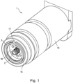
- figure 1 shows an oblique view of a planetary roller screw 1 according to the invention in the retracted state.
- figure 2 shows the planetary roller screw in the extended state.
- the planetary roller screw has an outer housing 13, a first telescopic sleeve 14 that can be extended from the housing, and a second telescopic sleeve 3 that can be extended from the first telescopic sleeve. Both telescopic sleeves are guided in relation to the housing 13 in a rotationally fixed manner.
- the first telescopic sleeve 14 has a longitudinal slot 16 for this purpose, in which a corresponding guide pin 17 of the housing 13 and a corresponding guide pin 18 of the second telescopic sleeve 3 are accommodated and guided.
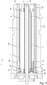
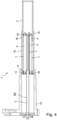
- the Figures 3 and 4 each show longitudinal sections of the planetary roller screw according to the invention in the retracted and in the extended state.
- a spindle 2 with an external thread 5 serves as the drive, the axis 15 of which simultaneously forms the axis of the housing 13 and of the two telescopic sleeves.
- a total of three planetary rollers 4 with an external thread 7 are arranged between the spindle 2 and the second telescopic sleeve 3 designed as a screw nut in such a way that the external thread 7 of the planetary rollers 4 engages both with the external thread 5 of the spindle and with an internal thread 6 of the screw nut 3 stands.
- the three planetary rollers 4 are rotatably mounted in relation to the spindle 2, the housing 13 and the two telescopic sleeves 14 and 3 via two planetary roller carriers 19 arranged at the axial ends.
- the planetary rollers 4 not only have a threaded section with the external thread 7, but also an axially adjoining external toothing 9, which is formed by an attached pinion 10 in each case.
- the pinions 10 with external teeth 9 mesh both with an external toothing 8 of the spindle 2 and with an internal toothing 12 of a ring gear 11 designed as a ring gear ring, which is firmly connected to the first telescopic sleeve 14 .
- the external toothing 8 of the spindle 2 is introduced into the external thread 5 of the spindle 2 in such a way that the external thread 5 and the external toothing 8 overlap over the entire length of the external thread 5 .
- the toothing height of the external toothing is smaller than the height of the threads of the external thread 5, so that the threads of the planetary rollers 4 and the spindle 2 can always mesh properly.
- the external gears 8 and 9 and the internal gear 12 are designed as helical gears in order to increase the overlap of the meshing.
- figure 7 shows a modification of the planetary roller screw 1 according to the invention from the Figures 1 to 6 according to a second embodiment.
- the basic structure essentially corresponds to the planetary roller screw 1 according to the first embodiment.
- the housing and the planetary roller carrier have not been shown.
- only one planetary roller 4 is shown.
- the planetary roller screw drive 1 has three planetary rollers, although the number of planetary rollers can, of course, also be larger.
- the planetary rollers 4 have a continuous threaded section with an external thread 7, the external toothing 9 of the planetary rollers 4 not being formed by an additionally provided pinion but being introduced into the external thread 7 of the planetary rollers 4.
- the external toothing 9 exists over the entire length of the external thread 7.
- the spindle 2 has a threaded section with an external thread 5, in which no external toothing is introduced. Instead, two pinions 10.1 and 10.2, through which the external toothing 8 of the spindle is formed, close axially before and after the threaded section.
- the threaded portion of the spindle 2 can be made significantly shorter than in the first embodiment.
- the threaded section and the two pinions 10.1 and 10.2 together extend over just over half the total length of the spindle 2. They are arranged towards the distal end of the spindle.
- the proximal section of the spindle is formed by a shank 20 with a significantly smaller diameter than the threaded section, as a result of which weight and the mass moved thereby can be saved.
- the pinion 10.2 located at the distal end of the spindle 2 is not in this case engagement with the planetary rollers. If the planetary roller screw is extended, the pinion 10.2 arranged at the distal end of the spindle 2 first engages with the outer teeth 9 of the planetary rollers 4. In the further course, the pinion 10.1 disengages from the outer teeth 9 of the planetary rollers 4, so that in the complete extended state, only the pinion 10.2 is in engagement with the external teeth 9 of the planetary rollers 4.
Landscapes
- Engineering & Computer Science (AREA)
- General Engineering & Computer Science (AREA)
- Mechanical Engineering (AREA)
- Transmission Devices (AREA)
Description
- Die vorliegende Erfindung betrifft einen Planetenrollengewindetrieb nach dem Oberbegriff des unabhängigen Anspruchs 1.
- Bei bekannten Planetenrollengewindetrieben, die als Teleskopspindel geeignet sind, wälzt ein Satz Planetenrollen zum einen auf einer zentralen Spindel und zum anderen auf einem Innengewinde einer Hohlradhülse ab. Aufgrund der von den Durchmesserverhältnissen abhängigen unterschiedlichen Drehzahlen der Spindel, der Planetenrollen bzw. der Hohlradhülse ergeben sich Steigungsdifferenzen, welche die gewünschte synchrone Hubbewegung erzeugen. Die zentrale Spindel hat dabei zwar die gleiche Anzahl an Gewindegängen wie die Planetenrollen aber im Vergleich zu den Planetenrollen einen kleineren Durchmesser. Das Gewinde der Hohlradhülse hat in der Regel die doppelte Anzahl an Gewindegängen wie die Planetenrollen. Die Wälzbewegung der Planetenrollen ist bei diesen bekannten Planetenrollengewindetrieben mit Schlupf verbunden, welcher nicht konstant ist, sondern von der Last abhängt. Sofern die Teleskopspindel als Aktuator eingesetzt werden soll, führt der Schlupf zu Ungenauigkeiten bei der Positionierung.
- Planetenrollengewindetriebe sind beispielsweise aus
DE 102015218621 A1 undEP 1 918 612 A1 bekannt. Die ausDE 102015218621 A1 undEP 1 918 612 A1 bekannten Planetenrollengewindetriebe sind jedoch nicht für eine Teleskopspindel geeignet, da eine relative axiale Verschiebung zwischen der Spindel und den Planetenrollen nicht möglich ist. - Ein Planetenrollengewindetrieb der gattungsgemäßen Art ist beispielsweise aus der
DE 10 2017 126570 A1 bekannt. Dieser gattungsgemäße Planetenrollengewindetrieb weist eine Spindel mit einem Außengewinde, eine Schraubenmutter mit einem Innengewinde, sowie Planetenrollen auf, die zwischen der Spindel und der Schraubenmutter angeordnet sind und jeweils ein Außengewinde aufweisen, das sowohl mit dem Außengewinde der Spindel als auch mit dem Innengewinde der Schraubenmutter in Eingriff steht, wobei sowohl die Spindel als auch die Planetenrollen ferner jeweils eine Außenverzahnung aufweisen, und wobei die Außenverzahnung der Spindel mit der Außenverzahnung der Planetenrollen kämmt, wobei die Außenverzahnung der Spindel in das Außengewinde der Spindel und/oder die Außenverzahnung der Planetenrollen in das Außengewinde der Planetenrollen eingebracht sind, sodass Spindel und/oder Planetenrollen einen Überlagerungsabschnitt aufweisen, in dem sich das jeweilige Außengewinde und die jeweilige Außenverzahnung überlagern, derart dass eine relative axiale Verschiebung zwischen der Spindel und den Planetenrollen möglich ist, wobei der Planetenrollengewindetrieb ferner ein Hohlrad mit einer Innenverzahnung aufweist, wobei die Schraubenmutter drehfest in Bezug auf das Hohlrad ist, und wobei die Außenverzahnung der Planetenrollen mit der Innenverzahnung des Hohlrads kämmt. Der ausDE 10 2017 126570 A1 bekannte Planetenrollengewindetrieb ist jedoch nicht für eine Teleskopspindel geeignet. - Aufgabe der vorliegenden Erfindung ist es, einen Planetenrollengewindetrieb anzugeben, der für eine Teleskopspindel geeignet ist und bei welchem der oben angesprochene Schlupf reduziert ist.
- Die Aufgabe wird gelöst durch die Merkmale des unabhängigen Anspruchs 1. Demnach liegt bei einem Planetenrollengewindetrieb nach dem Oberbegriff des unabhängigen Anspruchs 1 dann eine erfindungsgemäße Lösung der Aufgabe vor, wenn der Planetenrollengewindetrieb ein Gehäuse aufweist, an dem die Spindel drehbar gelagert ist, wobei das Hohlrad drehfest und axial verschieblich in Bezug auf das Gehäuse ist, wobei ferner die Schraubenmutter axial verschieblich in Bezug auf das Hohlrad gelagert ist, und wobei Durchmesserverhältnisse zwischen Spindel, Planetenrollen und Schraubenmutter derart gewählt sind, dass bei einer Rotation der Spindel sowohl eine relative axiale Verschiebung des Hohlrads in Bezug auf das Gehäuse als auch eine relative axiale Verschiebung der Schraubenmutter in Bezug auf das Hohlrad stattfindet..
- Dadurch ist der Planetenrollengewindetrieb als kompakt bauende Teleskopspindel einsetzbar.
- Durch den Eingriff der Außenverzahnungen von Spindel und Planetenrollen wird ein Schlupf zwischen Spindel und Planetenrollen unterbunden. Durch die Verzahnungen werden ferner die Drehzahlen der beteiligten Bauteile bestimmt. Die erfindungsgemäße Lösung erlaubt ferner eine kompakte Bauweise.
- Spindel und Schraubenmutter sind vorzugsweise koaxial angeordnet. Weiter vorzugsweise weisen die Planetenrollen alle denselben Außendurchmesser auf. Besonders bevorzugt sind drei Planetenrollen vorgesehen, da sich bei dieser Ausführung ein Hubverhältnis von 1:2 einstellt. Alternativ können aber auch vier oder mehr Planetenrollen vorgesehen sein. Weitere vorteilhafte Ausführungsformen der vorliegenden Erfindung sind Gegenstand der Unteransprüche.
- Gemäß einer bevorzugten Ausführungsform der vorliegenden Erfindung ist entweder die Außenverzahnung der Spindel in das Außengewinde der Spindel eingebracht, wobei sich die Außenverzahnung der Planetenrollen in einem axial außerhalb des Außengewindes der Planetenrollen bestehenden Abschnitt befindet, oder die Außenverzahnung der Planetenrollen ist in das Außengewinde der Planetenrollen eingebracht, wobei sich die Außenverzahnung der Spindel in einem axial außerhalb des Außengewindes der Spindel bestehenden Abschnitt befindet. Diese Ausführungsform lässt sich einfach herstellen und reduziert den Fertigungsaufwand. Das Bauteil, bei dem sich die Außenverzahnung und das Außengewinde nicht überlagern, kann einen einfachen Gewindeabschnitt mit einem axial daran anschließenden und einfach zu fertigenden Ritzel aufweisen.
- Bevorzugt ist die Außenverzahnung der Spindel in das Außengewinde der Spindel eingebracht, wobei sich Außenverzahnung und Außengewinde der Planetenrollen nicht überlagern. Diese Ausführungsform lässt sich besonders einfach fertigen.
- Gemäß einer besonders bevorzugten Ausführungsform ist die Außenverzahnung der Planetenrollen in das Außengewinde der Planetenrollen eingebracht, wobei sich die Außenverzahnung der Spindel in einem axial außerhalb des Außengewindes der Spindel bestehenden Abschnitt befindet. Um dabei sicherzustellen, dass die Außenverzahnung der Spindel trotz besonders kompakter Bauweise stets in das Außengewinde der Planetenrollen eingreift, kann gemäß einer vorteilhaften Ausführungsform vorgesehen sein, dass die Außenverzahnung der Spindel axial sowohl vor als auch nach dem Außengewinde der Spindel vorhanden ist. Vorteilhafterweise ist die Außenverzahnung der Spindel dabei durch zwei Ritzel gebildet, zwischen welchen sich das Außengewinde der Spindel erstreckt. Weiter vorzugsweise ist eines der beiden Ritzel ungefähr in der Mitte der Spindel angeordnet ist, wobei das andere der beiden Ritzel am distalen Ende der Spindel angeordnet ist. Ungefähr in der Mitte der Spindel bedeutet in diesem Zusammenhang in einem Bereich zwischen 35 % und 65 % der Gesamtlänge der Spindel, vorzugsweise in einem Bereich zwischen 40 % und 60 % der Gesamtlänge der Spindel. Unter dem distalen Ende wird in diesem Zusammenhang dasjenige Ende verstanden, welches in derjenigen Richtung, in welcher der Planetenrollengewindetrieb ausgefahren wird, vorne liegt. Das proximale Ende der Spindel ist demnach das gegenüberliegende Ende, welches zum feststehenden Ende des Planetenrollengewindetriebs weist. Von ganz besonderem Vorteil ist es, wenn ein proximaler Abschnitt der Spindel, in welchem weder Außengewinde noch Außenverzahnung der Spindel bestehen, durch einen Schaft gebildet ist, dessen Durchmesser vorzugsweise kleiner ist als ein Außendurchmesser des Außengewindes der Spindel und insbesondere kleiner als die Hälfte eines Außendurchmessers des Außengewindes der Spindel ist. Dadurch kann Gewicht und somit bewegte Masse eingespart werden.
- In einer weiteren bevorzugten Ausführungsform der vorliegenden Erfindung weist der Überlagerungsabschnitt eine Länge auf, die zumindest 80 % der Länge des jeweiligen Außengewindes beträgt. Sofern der erfindungsgemäße Planetenrollengewindetrieb als Teleskopspindel zum Einsatz kommt, ergibt sich dadurch ein großer Verstellbereich. Besonders bevorzugt nimmt der Überlagerungsabschnitt die gesamte Länge des jeweiligen Außengewindes ein.
- Gemäß einer weiteren bevorzugten Ausführungsform der vorliegenden Erfindung ist im Überlagerungsabschnitt eine in radialer Richtung gemessene Verzahnungshöhe der jeweiligen Außenverzahnung kleiner als eine ebenfalls in radialer Richtung gemessene Höhe der Gewindegänge des jeweiligen Außengewindes. Dadurch wird sichergestellt, dass die Gewindegänge der Außengewinde der Planetenrollen und der Spindel stets einwandfrei ineinandergreifen.
- Alternativ oder zusätzlich kann vorteilhafter Weise vorgesehen sein, dass die Außenverzahnungen als Schrägverzahnungen ausgeführt sind. Dadurch wird auch die Überdeckung des Zahneingriffs zwischen den Planetenrollen und der Spindel erhöht.
- Vorzugsweise handelt es sich bei dem Hohlrad um einen Hohlradring mit einer im Vergleich zur Schraubenmutter geringen axialen Ausdehnung.
- Besonders bevorzugt ist es dabei, wenn das Hohlrad fest mit einer aus dem Gehäuse ausfahrbaren ersten Teleskophülse verbunden oder durch diese erste Teleskophülse gebildet ist, wobei die Schraubenmutter fest mit einer aus der ersten Teleskophülse ausfahrbaren zweiten Teleskophülse verbunden oder durch diese zweite Teleskophülse gebildet ist. Bei dieser Ausführungsform ergibt sich ein stabiler und gegen äußere Einflüsse geschützter Teleskopspindelantrieb.
- Ausführungsbeispiele der vorliegenden Erfindung werden im Folgenden anhand von Zeichnungen näher erläutert.
- Es zeigen:
- Figur 1:
- einen als schlupffreie Teleskopspindel ausgeführten Planetenrollengewindetrieb in einer Schrägansicht im komplett eingefahrenen Zustand gemäß einem ersten Ausführungsbeispiel,
- Figur 2:
- den Planetenrollengewindetrieb aus
Figur 1 ebenfalls in Schrägansicht im komplett ausgefahrenen Zustand, - Figur 3:
- einen Längsschnitt des Planetenrollengewindetriebs aus den
Figuren 1 und2 im komplett eingefahrenen Zustand, - Figur 4:
- einen Längsschnitt des Planetenrollengewindetriebs aus den
Figuren 1 bis 3 im komplett ausgefahrenen Zustand, - Figur 5:
- eine Detailansicht des Längsschnitts aus
Figur 4 in einer perspektivischen Darstellung, - Figur 6:
- eine weitere Detailansicht des Längsschnitts aus
Figur 4 in einer weiteren perspektivischen Darstellung, und - Figur 7:
- eine Abwandlung des Planetenrollengewindetriebs gemäß einem zweiten Ausführungsbeispiel in einem perspektivischen Längsschnitt.
- Für die folgenden Ausführungen gilt, dass gleiche Teile durch gleiche Bezugszeichen bezeichnet sind. Sofern in einer Figur Bezugszeichen enthalten sind, auf die in der zugehörigen Figurenbeschreibung nicht näher eingegangen wird, so wird auf vorangehende oder nachfolgende Figurenbeschreibungen Bezug genommen.
-
Figur 1 zeigt eine Schrägansicht eines erfindungsgemäßen Planetenrollengewindetriebs 1 im eingefahrenen Zustand.Figur 2 zeigt den Planetenrollengewindetrieb im ausgefahrenen Zustand. Der Planetenrollengewindetrieb weist ein äu ßeres Gehäuse 13, eine aus dem Gehäuse ausfahrbare erste Teleskophülse 14 sowie eine aus der ersten Teleskophülse ausfahrbare zweite Teleskophülse 3 auf. Beide Teleskophülsen sind drehfest in Bezug auf das Gehäuse 13 geführt. Wie insbesondere aus denFiguren 2 und5 hervorgeht, weist die erste Teleskophülse 14 hierfür einen Längsschlitz 16 auf, in welchem ein entsprechender Führungszapfen 17 des Gehäuses 13 sowie ein entsprechender Führungszapfen 18 der zweiten Teleskophülse 3 aufgenommen und geführt sind. - Die
Figuren 3 und4 zeigen jeweils Längsschnitte des erfindungsgemäßen Planetenrollengewindetriebs im eingefahrenen und im ausgefahrenen Zustand. Als Antrieb dient eine Spindel 2 mit einem Außengewinde 5, deren Achse 15 gleichzeitig die Achse des Gehäuses 13 sowie der beiden Teleskophülsen bildet. Insgesamt drei Planetenrollen 4 mit Außengewinde 7 sind derart zwischen der Spindel 2 und der als Schraubenmutter ausgeführten zweiten Teleskophülse 3 angeordnet, dass das Außengewinde 7 der Planetenrollen 4 sowohl mit dem Außengewinde 5 der Spindel als auch mit einem Innengewinde 6 der Schraubenmutter 3 in Eingriff steht. Die drei Planetenrollen 4 sind über zwei an den axialen Enden angeordnete Planetenrollenträger 19 drehbar in Bezug auf die Spindel 2, das Gehäuse 13 und die beiden Teleskophülsen 14 und 3 gelagert. - Wie insbesondere aus den
Figuren 5 und6 hervorgeht, weisen die Planetenrollen 4 nicht nur einen Gewindeabschnitt mit dem Außengewinde 7, sondern auch eine axial daran anschlie-ßende Au βenverzahnung 9 auf, die jeweils durch ein aufgesetztes Ritzel 10 gebildet wird. Die Ritzel 10 mit Außenverzahnung 9 kämmen sowohl mit einer Außenverzahnung 8 der Spindel 2 als auch mit einer Innenverzahnung 12 eines als Hohlradring ausgeführten Hohlrads 11, welches fest mit der ersten Teleskophülse 14 verbunden ist. - Die Außenverzahnung 8 der Spindel 2 ist bei diesem Ausführungsbeispiel in das Außengewinde 5 der Spindel 2 eingebracht, und zwar so, dass sich das Außengewinde 5 und die Au-βenverzahnung 8 auf der gesamten Länge des Außengewindes 5 überlagern. Dadurch wird eine relative axiale Verschiebung zwischen der Spindel 2 und den Planetenrollen 4 ermöglicht. Die Verzahnungshöhe der Außenverzahnung ist dabei kleiner als die Höhe der Gewindegänge des Außengewindes 5, sodass die Gewindegänge der Planetenrollen 4 und der Spindel 2 stets einwandfrei ineinandergreifen können. Die Außenverzahnungen 8 und 9 sowie die Innenverzahnung 12 sind als Schrägverzahnungen ausgeführt, um die Überdeckung des Zahneingriffs zu erhöhen.
-
Figur 7 zeigt eine Abwandlung des erfindungsgemäßen Planetenrollengewindetriebs 1 aus denFiguren 1 bis 6 gemäß einem zweiten Ausführungsbeispiel. Der grundsätzliche Aufbau entspricht im Wesentlichen dem Planetenrollengewindetrieb 1 gemäß dem ersten Ausführungsbeispiel. Der Übersichtlichkeit halber wurde auf die Darstellung des Gehäuses und der Planetenrollenträger verzichtet. Ferner ist nur eine Planetenrolle 4 dargestellt. Der Planetenrollengewindetrieb 1 weist analog zum ersten Ausführungsbeispiel drei Planetenrollen auf, wobei die Anzahl der Planetenrollen selbstverständlich auch größer sein kann. - In Abweichung zum ersten Ausführungsbeispiel weisen die Planetenrollen 4 einen durchgehenden Gewindeabschnitt mit einem Außengewinde 7 auf, wobei die Außenverzahnung 9 der Planetenrollen 4 nicht durch ein zusätzlich vorgesehenes Ritzel gebildet wird sondern in das Außengewinde 7 der Planetenrollen 4 eingebracht ist. Die Außenverzahnung 9 besteht über die gesamte Länge des Außengewindes 7. Die Spindel 2 weist bei diesem Ausführungsbeispiel einen Gewindeabschnitt mit einem Außengewinde 5 auf, in welchen keine Außenverzahnung eingebracht ist. Anstatt dessen schließen sich axial vor und nach dem Gewindeabschnitt zwei Ritzel 10.1 und 10.2 an, durch welche die Außenverzahnung 8 der Spindel gebildet wird.
- Beim zweiten Ausführungsbeispiel kann der Gewindeabschnitt der Spindel 2 bedeutend kürzer ausgeführt werden als beim ersten Ausführungsbeispiel. Der Gewindeabschnitt und die beiden Ritzel 10.1 und 10.2 erstrecken sich zusammen lediglich über etwas mehr als die Hälfte der Gesamtlänge der Spindel 2. Sie sind dabei zum distalen Ende der Spindel hin angeordnet. Der proximale Abschnitt der Spindel wird durch einen Schaft 20 mit einem im Vergleich zum Gewindeabschnitt deutlich kleineren Durchmesser gebildet, wodurch Gewicht und dadurch bewegte Masse eingespart werden kann. Im komplett eingefahrenen Zustand des Planetenrollengewindetriebs 1 befindet sich bei dieser Ausführungsvariante lediglich das etwa in der Mitte der Spindel angeordnete Ritzel 10.1 in Eingriff mit den Planetenrollen bzw. mit deren Außenverzahnung 9. Das am distalen Ende der Spindel 2 angeordnete Ritzel 10.2 befindet sich dabei nicht in Eingriff mit den Planetenrollen. Wird der Planetenrollengewindetrieb ausgefahren, so kommt zunächst das am distalen Ende der Spindel 2 angeordnete Ritzel 10.2 in Eingriff mit der Au βenverzahnung 9 der Planetenrollen 4. Im weiteren Verlauf kommt das Ritzel 10.1 außer Eingriff mit der Außenverzahnung 9 der Planetenrollen 4, sodass sich im komplett ausgefahrenen Zustand nur das Ritzel 10.2 in Eingriff mit der Außenverzahnung 9 der Planetenrollen 4 befindet.
-
- 1
- Planetenrollengewindetrieb
- 2
- Spindel
- 3
- Schraubenmutter (Zweite Teleskophülse)
- 4
- Planetenrolle
- 5
- Außengewinde der Spindel
- 6
- Innengewinde der Schraubenmutter
- 7
- Außengewinde der Planetenrollen
- 8
- Außenverzahnung der Spindel
- 9
- Außenverzahnung der Planetenrollen
- 10
- Ritzel
- 10.1
- Ritzel
- 10.2
- Ritzel
- 11
- Hohlrad
- 12
- Innenverzahnung des Hohlrads
- 13
- Gehäuse
- 14
- Erste Teleskophülse
- 15
- Achse des Planetenrollengewindetriebs
- 16
- Längsschlitz der ersten Teleskophülse
- 17
- Führungszapfen des Gehäuses
- 18
- Führungszapfen der zweiten Teleskophülse
- 19
- Planetenrollenträger
- 20
- Schaft
Claims (13)
- Planetenrollengewindetrieb (1) miteiner Spindel (2) mit einem Außengewinde (5),einer Schraubenmutter (3) mit einem Innengewinde (6),und mit Planetenrollen (4), die zwischen der Spindel (2) und der Schraubenmutter (3) angeordnet sind und jeweils ein Außengewinde (7) aufweisen, das sowohl mit dem Außengewinde (5) der Spindel (2) als auch mit dem Innengewinde (6) der Schraubenmutter (3) in Eingriff steht,wobei sowohl die Spindel (2) als auch die Planetenrollen (4) ferner jeweils eine Außenverzahnung (8, 9) aufweisen, und wobei die Außenverzahnung (8) der Spindel (2) mit der Außenverzahnung (9) der Planetenrollen (4) kämmt,wobei die Außenverzahnung (8) der Spindel (2) in das Außengewinde (5) der Spindel (2) und/oder die Außenverzahnung (9) der Planetenrollen (4) in das Außengewinde (7) der Planetenrollen (4) eingebracht sind, sodass Spindel (2) und/oder Planetenrollen (4) einen Überlagerungsabschnitt aufweisen, in dem sich das jeweilige Außengewinde (5, 7) und die jeweilige Außenverzahnung (8, 9) überlagern, derart dass eine relative axiale Verschiebung zwischen der Spindel (2) und den Planetenrollen (4) möglich ist, wobei der Planetenrollengewindetrieb (1) ferner ein Hohlrad (11) mit einer Innenverzahnung (12) aufweist, wobei die Schraubenmutter (3) drehfest in Bezug auf das Hohlrad (11) ist, und wobei die Außenverzahnung (9) der Planetenrollen (4) mit der Innenverzahnung (12) des Hohlrads (11) kämmt, und wobei der Planetenrollengewindetrieb (1) ein Gehäuse (13) aufweist, an dem die Spindel (2) drehbar gelagert ist,dadurch gekennzeichnet, dass das Hohlrad (11) drehfest und axial verschieblich in Bezug auf das Gehäuse (13) ist, wobei ferner die Schraubenmutter (3) axial verschieblich in Bezug auf das Hohlrad (11) gelagert ist, und wobei Durchmesserverhältnisse zwischen Spindel (2), Planetenrollen (4) und Schraubenmutter (3) derart gewählt sind, dass bei einer Rotation der Spindel (2) sowohl eine relative axiale Verschiebung des Hohlrads (11) in Bezug auf das Gehäuse (13) als auch eine relative axiale Verschiebung der Schraubenmutter (3) in Bezug auf das Hohlrad (11) stattfindet.
- Planetenrollengewindetrieb (1) nach Anspruch 1, dadurch gekennzeichnet, dass entweder die Außenverzahnung (8) der Spindel (2) in das Außengewinde (5) der Spindel (2) eingebracht ist, wobei sich die Außenverzahnung (9) der Planetenrollen (4) in einem axial außerhalb des Außengewindes (7) der Planetenrollen (4) bestehenden Abschnitt befindet, oder die Außenverzahnung (9) der Planetenrollen (4) in das Außengewinde (7) der Planetenrollen (4) eingebracht ist, wobei sich die Außenverzahnung (8) der Spindel (2) in einem axial außerhalb des Außengewindes (5) der Spindel (2) bestehenden Abschnitt befindet.
- Planetenrollengewindetrieb (1) nach Anspruch 2, dadurch gekennzeichnet, dass die Außenverzahnung (8) der Spindel (2) in das Außengewinde (5) der Spindel (2) eingebracht ist.
- Planetenrollengewindetrieb (1) nach Anspruch 2, dadurch gekennzeichnet, dass die Außenverzahnung (9) der Planetenrollen (4) in das Außengewinde (7) der Planetenrollen (4) eingebracht ist, wobei sich die Außenverzahnung (8) der Spindel (2) in einem axial außerhalb des Außengewindes (5) der Spindel (2) bestehenden Abschnitt befindet.
- Planetenrollengewindetrieb (1) nach Anspruch 4, dadurch gekennzeichnet, dass die Außenverzahnung (8) der Spindel (2) axial sowohl vor als auch nach dem Außengewinde (5) der Spindel (2) vorhanden ist.
- Planetenrollengewindetrieb (1) nach Anspruch 5, dadurch gekennzeichnet, dass die Außenverzahnung (8) der Spindel (2) durch zwei Ritzel (10.1, 10.2) gebildet ist, zwischen welchen sich das Außengewinde (5) der Spindel (2) erstreckt.
- Planetenrollengewindetrieb (1) nach Anspruch 6, dadurch gekennzeichnet, dass eines der beiden Ritzel (10.1, 10.2) ungefähr in der Mitte der Spindel (2) angeordnet ist, wobei das andere der beiden Ritzel (10.1, 10.2) am distalen Ende der Spindel (2) angeordnet ist.
- Planetenrollengewindetrieb (1) nach einem der Ansprüche 4 bis 7, dadurch gekennzeichnet, dass ein proximaler Abschnitt der Spindel (2), in welchem weder Außengewinde (5) noch Außenverzahnung (8) der Spindel (2) bestehen, durch einen Schaft (20) gebildet ist, dessen Durchmesser kleiner ist als ein Außendurchmesser des Außengewindes (5) der Spindel (2) und insbesondere kleiner als die Hälfte eines Außendurchmessers des Außengewindes (5) der Spindel (2) ist.
- Planetenrollengewindetrieb (1) nach einem der Ansprüche 1 bis 8, dadurch gekennzeichnet, dass der Überlagerungsabschnitt eine Länge aufweist, die zumindest 80 % der Länge des jeweiligen Außengewindes (5, 7) beträgt.
- Planetenrollengewindetrieb (1) nach Anspruch 9, dadurch gekennzeichnet, dass der Überlagerungsabschnitt die gesamte Länge des jeweiligen Außengewindes (5, 7) einnimmt.
- Planetenrollengewindetrieb (1) nach einem der Ansprüche 1 bis 10, dadurch gekennzeichnet, dass im Überlagerungsabschnitt eine Verzahnungshöhe der jeweiligen Außenverzahnung (8, 9) kleiner ist als eine Höhe der Gewindegänge des jeweiligen Außengewindes (5, 7).
- Planetenrollengewindetrieb (1) nach einem der Ansprüche 1 bis 11, dadurch gekennzeichnet, dass die Außenverzahnungen (8, 9) als Schrägverzahnungen ausgeführt sind.
- Planetenrollengewindetrieb (1) nach einem der Ansprüche 1 bis 12, dadurch gekennzeichnet, dass das Hohlrad (11) fest mit einer aus dem Gehäuse (13) ausfahrbaren ersten Teleskophülse (14) verbunden oder durch diese erste Teleskophülse (14) gebildet ist, wobei die Schraubenmutter (3) fest mit einer aus der ersten Teleskophülse (14) ausfahrbaren zweiten Teleskophülse verbunden oder durch diese zweite Teleskophülse gebildet ist.
Priority Applications (2)
| Application Number | Priority Date | Filing Date | Title |
|---|---|---|---|
| EP19206020.0A EP3816479B1 (de) | 2019-10-29 | 2019-10-29 | Planetenrollengewindetrieb für eine schlupffreie teleskopspindel |
| PCT/EP2020/080374 WO2021083994A1 (en) | 2019-10-29 | 2020-10-29 | Device for regulating the concentration of glucose in the blood of a person |
Applications Claiming Priority (1)
| Application Number | Priority Date | Filing Date | Title |
|---|---|---|---|
| EP19206020.0A EP3816479B1 (de) | 2019-10-29 | 2019-10-29 | Planetenrollengewindetrieb für eine schlupffreie teleskopspindel |
Publications (2)
| Publication Number | Publication Date |
|---|---|
| EP3816479A1 EP3816479A1 (de) | 2021-05-05 |
| EP3816479B1 true EP3816479B1 (de) | 2023-07-05 |
Family
ID=68392815
Family Applications (1)
| Application Number | Title | Priority Date | Filing Date |
|---|---|---|---|
| EP19206020.0A Active EP3816479B1 (de) | 2019-10-29 | 2019-10-29 | Planetenrollengewindetrieb für eine schlupffreie teleskopspindel |
Country Status (2)
| Country | Link |
|---|---|
| EP (1) | EP3816479B1 (de) |
| WO (1) | WO2021083994A1 (de) |
Citations (1)
| Publication number | Priority date | Publication date | Assignee | Title |
|---|---|---|---|---|
| EP1918612B1 (de) * | 2005-08-23 | 2010-05-26 | Toyota Jidosha Kabushiki Kaisha | Planetengetriebe zum wechseln zwischen drehbewegungen und linearen bewegungen |
Family Cites Families (7)
| Publication number | Priority date | Publication date | Assignee | Title |
|---|---|---|---|---|
| BE496556A (de) * | 1949-07-13 | |||
| US7063684B2 (en) * | 1999-10-28 | 2006-06-20 | Medtronic Minimed, Inc. | Drive system seal |
| NL1030272C1 (nl) | 2005-10-26 | 2007-04-27 | Variak | Inrichting voor het automatisch reguleren van de concentratie van glucose in het bloed van een diabetes-patient. |
| DE102010052918A1 (de) * | 2010-11-30 | 2012-05-31 | Schaeffler Technologies Gmbh & Co. Kg | Wagenheber |
| EP3142728B1 (de) * | 2014-05-14 | 2018-03-14 | Meamedical AG | Dosiervorrichtung für die abgabe von medikamentenfluid aus einem reservoir mit spindelstange zur verschiebung des kolbens |
| FR3026454B1 (fr) | 2014-09-29 | 2016-11-25 | Skf Ab | Mecanisme de vis a rouleaux et procede de fabrication associe |
| JP6531748B2 (ja) * | 2016-11-18 | 2019-06-19 | トヨタ自動車株式会社 | 動作変換機構およびそれを用いた電動ブレーキアクチュエータ |
-
2019
- 2019-10-29 EP EP19206020.0A patent/EP3816479B1/de active Active
-
2020
- 2020-10-29 WO PCT/EP2020/080374 patent/WO2021083994A1/en not_active Ceased
Patent Citations (1)
| Publication number | Priority date | Publication date | Assignee | Title |
|---|---|---|---|---|
| EP1918612B1 (de) * | 2005-08-23 | 2010-05-26 | Toyota Jidosha Kabushiki Kaisha | Planetengetriebe zum wechseln zwischen drehbewegungen und linearen bewegungen |
Also Published As
| Publication number | Publication date |
|---|---|
| WO2021083994A1 (en) | 2021-05-06 |
| EP3816479A1 (de) | 2021-05-05 |
Similar Documents
| Publication | Publication Date | Title |
|---|---|---|
| EP1828639B1 (de) | Zahnradpaarung aus kronenrad und ritzel | |
| EP2249681B1 (de) | Schubladenausziehführung mit einem Möbelantrieb | |
| EP1559494B1 (de) | Vorrichtung zur Bearbeitung von Rohrenden, insbesondere zum Schneiden von Gewindeanschlüssen | |
| DE3324494C1 (de) | Walzwerkzeug | |
| EP3765243A1 (de) | Armgelenk für einen manipulator und manipulator | |
| EP2886223B1 (de) | Gewinderollkopf | |
| DE4037130A1 (de) | Vorrichtung zum verstellen der falzklappen an einem falzklappenzylinder | |
| DE102015207558B4 (de) | Gurtaufroller | |
| EP3406939B1 (de) | Zahnradpaarung für ein schraubradgetriebe oder ein stirnradgetriebe, schraubradgetriebe oder stirnradgetriebe mit einer derartigen zahnradpaarung sowie verwendung einer derartigen zahnradpaarung in schraubradgetrieben und stirnradgetrieben | |
| DE102013209310A1 (de) | Schaltbares Planetengetriebe | |
| DE10148503B4 (de) | Falzapparat mit umfangsverstellbarem Zylinder | |
| DE2735166C2 (de) | Lenkgetriebe, insbesondere Spindellenkgetriebe mit veränderlicher Übersetzung | |
| EP3104503B1 (de) | Spielfreier drehantrieb | |
| EP1876430A2 (de) | Mechanischer Stell- oder Dosierknopf | |
| DE2531081A1 (de) | Lenk- oder steuergetriebe | |
| DE68903591T2 (de) | Kupplungsmechanismus in einem zahnradgetriebe. | |
| AT401282B (de) | Schaltgetriebe | |
| DD263639A5 (de) | Linearantriebseinheit | |
| DE20212935U1 (de) | Linearantrieb zum Verstellen beweglich gelagerter Teile | |
| EP3816479A1 (de) | Planetenrollengewindetrieb für eine schlupffreie teleskopspindel | |
| DE102007027219A1 (de) | Linearantrieb für eine Heckklappe oder dergleichen | |
| DE3508767C2 (de) | ||
| DE10133856B4 (de) | Werkzeugkopf insbesondere für Maschinen zur Herstellung von Gewindeanschlüssen an Rohrenden | |
| DE19723608C2 (de) | Falzapparat für Klappenfalz | |
| DE1931860A1 (de) | Vorrichtung zur Umwandlung einer Drehbewegung in eine geradlinige Vorschubbewegung |
Legal Events
| Date | Code | Title | Description |
|---|---|---|---|
| PUAI | Public reference made under article 153(3) epc to a published international application that has entered the european phase |
Free format text: ORIGINAL CODE: 0009012 |
|
| STAA | Information on the status of an ep patent application or granted ep patent |
Free format text: STATUS: THE APPLICATION HAS BEEN PUBLISHED |
|
| AK | Designated contracting states |
Kind code of ref document: A1 Designated state(s): AL AT BE BG CH CY CZ DE DK EE ES FI FR GB GR HR HU IE IS IT LI LT LU LV MC MK MT NL NO PL PT RO RS SE SI SK SM TR |
|
| STAA | Information on the status of an ep patent application or granted ep patent |
Free format text: STATUS: REQUEST FOR EXAMINATION WAS MADE |
|
| 17P | Request for examination filed |
Effective date: 20211025 |
|
| RBV | Designated contracting states (corrected) |
Designated state(s): AL AT BE BG CH CY CZ DE DK EE ES FI FR GB GR HR HU IE IS IT LI LT LU LV MC MK MT NL NO PL PT RO RS SE SI SK SM TR |
|
| GRAP | Despatch of communication of intention to grant a patent |
Free format text: ORIGINAL CODE: EPIDOSNIGR1 |
|
| STAA | Information on the status of an ep patent application or granted ep patent |
Free format text: STATUS: GRANT OF PATENT IS INTENDED |
|
| INTG | Intention to grant announced |
Effective date: 20230119 |
|
| GRAS | Grant fee paid |
Free format text: ORIGINAL CODE: EPIDOSNIGR3 |
|
| GRAA | (expected) grant |
Free format text: ORIGINAL CODE: 0009210 |
|
| STAA | Information on the status of an ep patent application or granted ep patent |
Free format text: STATUS: THE PATENT HAS BEEN GRANTED |
|
| AK | Designated contracting states |
Kind code of ref document: B1 Designated state(s): AL AT BE BG CH CY CZ DE DK EE ES FI FR GB GR HR HU IE IS IT LI LT LU LV MC MK MT NL NO PL PT RO RS SE SI SK SM TR |
|
| REG | Reference to a national code |
Ref country code: CH Ref legal event code: EP |
|
| REG | Reference to a national code |
Ref country code: AT Ref legal event code: REF Ref document number: 1585118 Country of ref document: AT Kind code of ref document: T Effective date: 20230715 |
|
| P01 | Opt-out of the competence of the unified patent court (upc) registered |
Effective date: 20230609 |
|
| REG | Reference to a national code |
Ref country code: DE Ref legal event code: R096 Ref document number: 502019008387 Country of ref document: DE |
|
| REG | Reference to a national code |
Ref country code: IE Ref legal event code: FG4D Free format text: LANGUAGE OF EP DOCUMENT: GERMAN |
|
| REG | Reference to a national code |
Ref country code: NL Ref legal event code: FP |
|
| REG | Reference to a national code |
Ref country code: LT Ref legal event code: MG9D |
|
| PG25 | Lapsed in a contracting state [announced via postgrant information from national office to epo] |
Ref country code: GR Free format text: LAPSE BECAUSE OF FAILURE TO SUBMIT A TRANSLATION OF THE DESCRIPTION OR TO PAY THE FEE WITHIN THE PRESCRIBED TIME-LIMIT Effective date: 20231006 |
|
| PG25 | Lapsed in a contracting state [announced via postgrant information from national office to epo] |
Ref country code: ES Free format text: LAPSE BECAUSE OF FAILURE TO SUBMIT A TRANSLATION OF THE DESCRIPTION OR TO PAY THE FEE WITHIN THE PRESCRIBED TIME-LIMIT Effective date: 20230705 |
|
| PG25 | Lapsed in a contracting state [announced via postgrant information from national office to epo] |
Ref country code: IS Free format text: LAPSE BECAUSE OF FAILURE TO SUBMIT A TRANSLATION OF THE DESCRIPTION OR TO PAY THE FEE WITHIN THE PRESCRIBED TIME-LIMIT Effective date: 20231105 |
|
| PG25 | Lapsed in a contracting state [announced via postgrant information from national office to epo] |
Ref country code: SE Free format text: LAPSE BECAUSE OF FAILURE TO SUBMIT A TRANSLATION OF THE DESCRIPTION OR TO PAY THE FEE WITHIN THE PRESCRIBED TIME-LIMIT Effective date: 20230705 Ref country code: RS Free format text: LAPSE BECAUSE OF FAILURE TO SUBMIT A TRANSLATION OF THE DESCRIPTION OR TO PAY THE FEE WITHIN THE PRESCRIBED TIME-LIMIT Effective date: 20230705 Ref country code: PT Free format text: LAPSE BECAUSE OF FAILURE TO SUBMIT A TRANSLATION OF THE DESCRIPTION OR TO PAY THE FEE WITHIN THE PRESCRIBED TIME-LIMIT Effective date: 20231106 Ref country code: NO Free format text: LAPSE BECAUSE OF FAILURE TO SUBMIT A TRANSLATION OF THE DESCRIPTION OR TO PAY THE FEE WITHIN THE PRESCRIBED TIME-LIMIT Effective date: 20231005 Ref country code: LV Free format text: LAPSE BECAUSE OF FAILURE TO SUBMIT A TRANSLATION OF THE DESCRIPTION OR TO PAY THE FEE WITHIN THE PRESCRIBED TIME-LIMIT Effective date: 20230705 Ref country code: LT Free format text: LAPSE BECAUSE OF FAILURE TO SUBMIT A TRANSLATION OF THE DESCRIPTION OR TO PAY THE FEE WITHIN THE PRESCRIBED TIME-LIMIT Effective date: 20230705 Ref country code: IS Free format text: LAPSE BECAUSE OF FAILURE TO SUBMIT A TRANSLATION OF THE DESCRIPTION OR TO PAY THE FEE WITHIN THE PRESCRIBED TIME-LIMIT Effective date: 20231105 Ref country code: HR Free format text: LAPSE BECAUSE OF FAILURE TO SUBMIT A TRANSLATION OF THE DESCRIPTION OR TO PAY THE FEE WITHIN THE PRESCRIBED TIME-LIMIT Effective date: 20230705 Ref country code: GR Free format text: LAPSE BECAUSE OF FAILURE TO SUBMIT A TRANSLATION OF THE DESCRIPTION OR TO PAY THE FEE WITHIN THE PRESCRIBED TIME-LIMIT Effective date: 20231006 Ref country code: FI Free format text: LAPSE BECAUSE OF FAILURE TO SUBMIT A TRANSLATION OF THE DESCRIPTION OR TO PAY THE FEE WITHIN THE PRESCRIBED TIME-LIMIT Effective date: 20230705 Ref country code: ES Free format text: LAPSE BECAUSE OF FAILURE TO SUBMIT A TRANSLATION OF THE DESCRIPTION OR TO PAY THE FEE WITHIN THE PRESCRIBED TIME-LIMIT Effective date: 20230705 |
|
| PG25 | Lapsed in a contracting state [announced via postgrant information from national office to epo] |
Ref country code: PL Free format text: LAPSE BECAUSE OF FAILURE TO SUBMIT A TRANSLATION OF THE DESCRIPTION OR TO PAY THE FEE WITHIN THE PRESCRIBED TIME-LIMIT Effective date: 20230705 |
|
| REG | Reference to a national code |
Ref country code: DE Ref legal event code: R097 Ref document number: 502019008387 Country of ref document: DE |
|
| PG25 | Lapsed in a contracting state [announced via postgrant information from national office to epo] |
Ref country code: SM Free format text: LAPSE BECAUSE OF FAILURE TO SUBMIT A TRANSLATION OF THE DESCRIPTION OR TO PAY THE FEE WITHIN THE PRESCRIBED TIME-LIMIT Effective date: 20230705 Ref country code: RO Free format text: LAPSE BECAUSE OF FAILURE TO SUBMIT A TRANSLATION OF THE DESCRIPTION OR TO PAY THE FEE WITHIN THE PRESCRIBED TIME-LIMIT Effective date: 20230705 Ref country code: EE Free format text: LAPSE BECAUSE OF FAILURE TO SUBMIT A TRANSLATION OF THE DESCRIPTION OR TO PAY THE FEE WITHIN THE PRESCRIBED TIME-LIMIT Effective date: 20230705 Ref country code: DK Free format text: LAPSE BECAUSE OF FAILURE TO SUBMIT A TRANSLATION OF THE DESCRIPTION OR TO PAY THE FEE WITHIN THE PRESCRIBED TIME-LIMIT Effective date: 20230705 Ref country code: CZ Free format text: LAPSE BECAUSE OF FAILURE TO SUBMIT A TRANSLATION OF THE DESCRIPTION OR TO PAY THE FEE WITHIN THE PRESCRIBED TIME-LIMIT Effective date: 20230705 Ref country code: SK Free format text: LAPSE BECAUSE OF FAILURE TO SUBMIT A TRANSLATION OF THE DESCRIPTION OR TO PAY THE FEE WITHIN THE PRESCRIBED TIME-LIMIT Effective date: 20230705 |
|
| PLBE | No opposition filed within time limit |
Free format text: ORIGINAL CODE: 0009261 |
|
| STAA | Information on the status of an ep patent application or granted ep patent |
Free format text: STATUS: NO OPPOSITION FILED WITHIN TIME LIMIT |
|
| PG25 | Lapsed in a contracting state [announced via postgrant information from national office to epo] |
Ref country code: MC Free format text: LAPSE BECAUSE OF FAILURE TO SUBMIT A TRANSLATION OF THE DESCRIPTION OR TO PAY THE FEE WITHIN THE PRESCRIBED TIME-LIMIT Effective date: 20230705 |
|
| 26N | No opposition filed |
Effective date: 20240408 |
|
| REG | Reference to a national code |
Ref country code: BE Ref legal event code: MM Effective date: 20231031 |
|
| PG25 | Lapsed in a contracting state [announced via postgrant information from national office to epo] |
Ref country code: LU Free format text: LAPSE BECAUSE OF NON-PAYMENT OF DUE FEES Effective date: 20231029 |
|
| PG25 | Lapsed in a contracting state [announced via postgrant information from national office to epo] |
Ref country code: LU Free format text: LAPSE BECAUSE OF NON-PAYMENT OF DUE FEES Effective date: 20231029 |
|
| PG25 | Lapsed in a contracting state [announced via postgrant information from national office to epo] |
Ref country code: SI Free format text: LAPSE BECAUSE OF FAILURE TO SUBMIT A TRANSLATION OF THE DESCRIPTION OR TO PAY THE FEE WITHIN THE PRESCRIBED TIME-LIMIT Effective date: 20230705 |
|
| PG25 | Lapsed in a contracting state [announced via postgrant information from national office to epo] |
Ref country code: BE Free format text: LAPSE BECAUSE OF NON-PAYMENT OF DUE FEES Effective date: 20231031 |
|
| PG25 | Lapsed in a contracting state [announced via postgrant information from national office to epo] |
Ref country code: IE Free format text: LAPSE BECAUSE OF NON-PAYMENT OF DUE FEES Effective date: 20231029 |
|
| PG25 | Lapsed in a contracting state [announced via postgrant information from national office to epo] |
Ref country code: IE Free format text: LAPSE BECAUSE OF NON-PAYMENT OF DUE FEES Effective date: 20231029 |
|
| PG25 | Lapsed in a contracting state [announced via postgrant information from national office to epo] |
Ref country code: BG Free format text: LAPSE BECAUSE OF FAILURE TO SUBMIT A TRANSLATION OF THE DESCRIPTION OR TO PAY THE FEE WITHIN THE PRESCRIBED TIME-LIMIT Effective date: 20230705 |
|
| PG25 | Lapsed in a contracting state [announced via postgrant information from national office to epo] |
Ref country code: BG Free format text: LAPSE BECAUSE OF FAILURE TO SUBMIT A TRANSLATION OF THE DESCRIPTION OR TO PAY THE FEE WITHIN THE PRESCRIBED TIME-LIMIT Effective date: 20230705 |
|
| PG25 | Lapsed in a contracting state [announced via postgrant information from national office to epo] |
Ref country code: CY Free format text: LAPSE BECAUSE OF FAILURE TO SUBMIT A TRANSLATION OF THE DESCRIPTION OR TO PAY THE FEE WITHIN THE PRESCRIBED TIME-LIMIT; INVALID AB INITIO Effective date: 20191029 |
|
| PG25 | Lapsed in a contracting state [announced via postgrant information from national office to epo] |
Ref country code: HU Free format text: LAPSE BECAUSE OF FAILURE TO SUBMIT A TRANSLATION OF THE DESCRIPTION OR TO PAY THE FEE WITHIN THE PRESCRIBED TIME-LIMIT; INVALID AB INITIO Effective date: 20191029 |
|
| REG | Reference to a national code |
Ref country code: CH Ref legal event code: U11 Free format text: ST27 STATUS EVENT CODE: U-0-0-U10-U11 (AS PROVIDED BY THE NATIONAL OFFICE) Effective date: 20251101 |
|
| PGFP | Annual fee paid to national office [announced via postgrant information from national office to epo] |
Ref country code: NL Payment date: 20251023 Year of fee payment: 7 |
|
| PG25 | Lapsed in a contracting state [announced via postgrant information from national office to epo] |
Ref country code: TR Free format text: LAPSE BECAUSE OF FAILURE TO SUBMIT A TRANSLATION OF THE DESCRIPTION OR TO PAY THE FEE WITHIN THE PRESCRIBED TIME-LIMIT Effective date: 20230705 |
|
| REG | Reference to a national code |
Ref country code: AT Ref legal event code: MM01 Ref document number: 1585118 Country of ref document: AT Kind code of ref document: T Effective date: 20241029 |
|
| PGFP | Annual fee paid to national office [announced via postgrant information from national office to epo] |
Ref country code: DE Payment date: 20251020 Year of fee payment: 7 |
|
| PGFP | Annual fee paid to national office [announced via postgrant information from national office to epo] |
Ref country code: GB Payment date: 20251024 Year of fee payment: 7 |
|
| PG25 | Lapsed in a contracting state [announced via postgrant information from national office to epo] |
Ref country code: AT Free format text: LAPSE BECAUSE OF NON-PAYMENT OF DUE FEES Effective date: 20241029 |
|
| PGFP | Annual fee paid to national office [announced via postgrant information from national office to epo] |
Ref country code: IT Payment date: 20251031 Year of fee payment: 7 |
|
| PGFP | Annual fee paid to national office [announced via postgrant information from national office to epo] |
Ref country code: FR Payment date: 20251029 Year of fee payment: 7 |
|
| PGFP | Annual fee paid to national office [announced via postgrant information from national office to epo] |
Ref country code: CH Payment date: 20251101 Year of fee payment: 7 |
|
| PGFP | Annual fee paid to national office [announced via postgrant information from national office to epo] |
Ref country code: AT Payment date: 20260410 Year of fee payment: 5 |