EP3813624B1 - Surveillance d'un programme de nettoyage d'un lave-vaisselle - Google Patents
Surveillance d'un programme de nettoyage d'un lave-vaisselle Download PDFInfo
- Publication number
- EP3813624B1 EP3813624B1 EP19734745.3A EP19734745A EP3813624B1 EP 3813624 B1 EP3813624 B1 EP 3813624B1 EP 19734745 A EP19734745 A EP 19734745A EP 3813624 B1 EP3813624 B1 EP 3813624B1
- Authority
- EP
- European Patent Office
- Prior art keywords
- information
- acceleration
- dishwasher
- sensor
- item
- Prior art date
- Legal status (The legal status is an assumption and is not a legal conclusion. Google has not performed a legal analysis and makes no representation as to the accuracy of the status listed.)
- Active
Links
Images


Classifications
-
- A—HUMAN NECESSITIES
- A47—FURNITURE; DOMESTIC ARTICLES OR APPLIANCES; COFFEE MILLS; SPICE MILLS; SUCTION CLEANERS IN GENERAL
- A47L—DOMESTIC WASHING OR CLEANING; SUCTION CLEANERS IN GENERAL
- A47L15/00—Washing or rinsing machines for crockery or tableware
- A47L15/0018—Controlling processes, i.e. processes to control the operation of the machine characterised by the purpose or target of the control
- A47L15/0055—Metering or indication of used products, e.g. type or quantity of detergent, rinse aid or salt; for measuring or controlling the product concentration
-
- A—HUMAN NECESSITIES
- A47—FURNITURE; DOMESTIC ARTICLES OR APPLIANCES; COFFEE MILLS; SPICE MILLS; SUCTION CLEANERS IN GENERAL
- A47L—DOMESTIC WASHING OR CLEANING; SUCTION CLEANERS IN GENERAL
- A47L15/00—Washing or rinsing machines for crockery or tableware
- A47L15/0018—Controlling processes, i.e. processes to control the operation of the machine characterised by the purpose or target of the control
- A47L15/0021—Regulation of operational steps within the washing processes, e.g. optimisation or improvement of operational steps depending from the detergent nature or from the condition of the crockery
- A47L15/0023—Water filling
-
- A—HUMAN NECESSITIES
- A47—FURNITURE; DOMESTIC ARTICLES OR APPLIANCES; COFFEE MILLS; SPICE MILLS; SUCTION CLEANERS IN GENERAL
- A47L—DOMESTIC WASHING OR CLEANING; SUCTION CLEANERS IN GENERAL
- A47L15/00—Washing or rinsing machines for crockery or tableware
- A47L15/0018—Controlling processes, i.e. processes to control the operation of the machine characterised by the purpose or target of the control
- A47L15/0021—Regulation of operational steps within the washing processes, e.g. optimisation or improvement of operational steps depending from the detergent nature or from the condition of the crockery
- A47L15/0026—Rinsing phases
-
- A—HUMAN NECESSITIES
- A47—FURNITURE; DOMESTIC ARTICLES OR APPLIANCES; COFFEE MILLS; SPICE MILLS; SUCTION CLEANERS IN GENERAL
- A47L—DOMESTIC WASHING OR CLEANING; SUCTION CLEANERS IN GENERAL
- A47L15/00—Washing or rinsing machines for crockery or tableware
- A47L15/0018—Controlling processes, i.e. processes to control the operation of the machine characterised by the purpose or target of the control
- A47L15/0021—Regulation of operational steps within the washing processes, e.g. optimisation or improvement of operational steps depending from the detergent nature or from the condition of the crockery
- A47L15/0028—Washing phases
-
- A—HUMAN NECESSITIES
- A47—FURNITURE; DOMESTIC ARTICLES OR APPLIANCES; COFFEE MILLS; SPICE MILLS; SUCTION CLEANERS IN GENERAL
- A47L—DOMESTIC WASHING OR CLEANING; SUCTION CLEANERS IN GENERAL
- A47L15/00—Washing or rinsing machines for crockery or tableware
- A47L15/0018—Controlling processes, i.e. processes to control the operation of the machine characterised by the purpose or target of the control
- A47L15/0021—Regulation of operational steps within the washing processes, e.g. optimisation or improvement of operational steps depending from the detergent nature or from the condition of the crockery
- A47L15/0034—Drying phases, including dripping-off phases
-
- A—HUMAN NECESSITIES
- A47—FURNITURE; DOMESTIC ARTICLES OR APPLIANCES; COFFEE MILLS; SPICE MILLS; SUCTION CLEANERS IN GENERAL
- A47L—DOMESTIC WASHING OR CLEANING; SUCTION CLEANERS IN GENERAL
- A47L15/00—Washing or rinsing machines for crockery or tableware
- A47L15/0018—Controlling processes, i.e. processes to control the operation of the machine characterised by the purpose or target of the control
- A47L15/0063—Controlling processes, i.e. processes to control the operation of the machine characterised by the purpose or target of the control using remote monitoring or controlling of the dishwasher operation, e.g. networking systems
-
- A—HUMAN NECESSITIES
- A47—FURNITURE; DOMESTIC ARTICLES OR APPLIANCES; COFFEE MILLS; SPICE MILLS; SUCTION CLEANERS IN GENERAL
- A47L—DOMESTIC WASHING OR CLEANING; SUCTION CLEANERS IN GENERAL
- A47L15/00—Washing or rinsing machines for crockery or tableware
- A47L15/42—Details
- A47L15/4287—Temperature measuring or regulating arrangements
-
- A—HUMAN NECESSITIES
- A47—FURNITURE; DOMESTIC ARTICLES OR APPLIANCES; COFFEE MILLS; SPICE MILLS; SUCTION CLEANERS IN GENERAL
- A47L—DOMESTIC WASHING OR CLEANING; SUCTION CLEANERS IN GENERAL
- A47L15/00—Washing or rinsing machines for crockery or tableware
- A47L15/42—Details
- A47L15/44—Devices for adding cleaning agents; Devices for dispensing cleaning agents, rinsing aids or deodorants
- A47L15/4445—Detachable devices
-
- A—HUMAN NECESSITIES
- A47—FURNITURE; DOMESTIC ARTICLES OR APPLIANCES; COFFEE MILLS; SPICE MILLS; SUCTION CLEANERS IN GENERAL
- A47L—DOMESTIC WASHING OR CLEANING; SUCTION CLEANERS IN GENERAL
- A47L15/00—Washing or rinsing machines for crockery or tableware
- A47L15/42—Details
- A47L15/44—Devices for adding cleaning agents; Devices for dispensing cleaning agents, rinsing aids or deodorants
- A47L15/449—Metering controlling devices
-
- A—HUMAN NECESSITIES
- A47—FURNITURE; DOMESTIC ARTICLES OR APPLIANCES; COFFEE MILLS; SPICE MILLS; SUCTION CLEANERS IN GENERAL
- A47L—DOMESTIC WASHING OR CLEANING; SUCTION CLEANERS IN GENERAL
- A47L2401/00—Automatic detection in controlling methods of washing or rinsing machines for crockery or tableware, e.g. information provided by sensors entered into controlling devices
- A47L2401/03—Operation mode, e.g. delicate washing, economy washing, reduced time, sterilizing, water softener regenerating, odor eliminating or service
-
- A—HUMAN NECESSITIES
- A47—FURNITURE; DOMESTIC ARTICLES OR APPLIANCES; COFFEE MILLS; SPICE MILLS; SUCTION CLEANERS IN GENERAL
- A47L—DOMESTIC WASHING OR CLEANING; SUCTION CLEANERS IN GENERAL
- A47L2401/00—Automatic detection in controlling methods of washing or rinsing machines for crockery or tableware, e.g. information provided by sensors entered into controlling devices
- A47L2401/12—Water temperature
-
- A—HUMAN NECESSITIES
- A47—FURNITURE; DOMESTIC ARTICLES OR APPLIANCES; COFFEE MILLS; SPICE MILLS; SUCTION CLEANERS IN GENERAL
- A47L—DOMESTIC WASHING OR CLEANING; SUCTION CLEANERS IN GENERAL
- A47L2401/00—Automatic detection in controlling methods of washing or rinsing machines for crockery or tableware, e.g. information provided by sensors entered into controlling devices
- A47L2401/20—Time, e.g. elapsed operating time
-
- A—HUMAN NECESSITIES
- A47—FURNITURE; DOMESTIC ARTICLES OR APPLIANCES; COFFEE MILLS; SPICE MILLS; SUCTION CLEANERS IN GENERAL
- A47L—DOMESTIC WASHING OR CLEANING; SUCTION CLEANERS IN GENERAL
- A47L2401/00—Automatic detection in controlling methods of washing or rinsing machines for crockery or tableware, e.g. information provided by sensors entered into controlling devices
- A47L2401/24—Spray arms status, e.g. detection of spray arm rotation
-
- A—HUMAN NECESSITIES
- A47—FURNITURE; DOMESTIC ARTICLES OR APPLIANCES; COFFEE MILLS; SPICE MILLS; SUCTION CLEANERS IN GENERAL
- A47L—DOMESTIC WASHING OR CLEANING; SUCTION CLEANERS IN GENERAL
- A47L2401/00—Automatic detection in controlling methods of washing or rinsing machines for crockery or tableware, e.g. information provided by sensors entered into controlling devices
- A47L2401/32—Vibration or sound detection
-
- A—HUMAN NECESSITIES
- A47—FURNITURE; DOMESTIC ARTICLES OR APPLIANCES; COFFEE MILLS; SPICE MILLS; SUCTION CLEANERS IN GENERAL
- A47L—DOMESTIC WASHING OR CLEANING; SUCTION CLEANERS IN GENERAL
- A47L2501/00—Output in controlling method of washing or rinsing machines for crockery or tableware, i.e. quantities or components controlled, or actions performed by the controlling device executing the controlling method
- A47L2501/07—Consumable products, e.g. detergent, rinse aids or salt
-
- A—HUMAN NECESSITIES
- A47—FURNITURE; DOMESTIC ARTICLES OR APPLIANCES; COFFEE MILLS; SPICE MILLS; SUCTION CLEANERS IN GENERAL
- A47L—DOMESTIC WASHING OR CLEANING; SUCTION CLEANERS IN GENERAL
- A47L2501/00—Output in controlling method of washing or rinsing machines for crockery or tableware, i.e. quantities or components controlled, or actions performed by the controlling device executing the controlling method
- A47L2501/26—Indication or alarm to the controlling device or to the user
Definitions
- Exemplary embodiments relate to a method for a dishwasher and a device for use in a dishwasher, in particular for monitoring a state of a cleaning program performed by the dishwasher.
- Dosing devices that operate at least partially independently are known, which can be arranged, for example, in a treatment chamber of a dishwasher and can dispense a plurality of different preparations into the washing process of the dishwasher.
- Such dosing devices typically work in combination with temperature and/or conductivity sensors.
- Conductivity sensors or resistance sensors in particular rely on the liquid to be tested being forced past the sensor so that the corresponding sensor can come into contact with the liquid.
- sensors are subject to constant chemical and physical stress as they are exposed to the cleaning process. Chemicals in the wash solution in particular can alter and damage the sensor contacts, as the sensors can, for example, become coated with substances, polarization can occur which can lead to incorrect measured values, and/or dirt deposits from the wash solution can render the sensors unusable, especially if the sensors are installed in low-flow installation situations within the treatment chamber of the dishwasher for the reasons mentioned above.
- a disadvantage is that, for example, temperature sensors used to control such a dosing device cannot ensure that a cleaning program is fully monitored, since, for example, in the context of a so-called zeolite-active drying process, dishes no longer need to be heated during the final rinse cycle.
- a temperature sensor used to identify the final rinse cycle is used, can no longer recognize the drying process in the above example.
- Documents DE102016225812 A1 , DE102008036586 A1 and US2016/143505 A1 provide examples of dosing devices that rely on sensor information to determine when to dispense detergent.
- the invention has the task of being able to clearly determine a state of a cleaning program of a dishwasher.
- the invention relates to a method according to the subject matter of independent claim 1. Further embodiments are described in the dependent claims.
- a device which is configured to control a method according to the first aspect.
- the device according to the second aspect may further comprise one or more sensors and/or one or more communication interfaces.
- a communication interface is understood to mean, for example, a wireless communication interface and/or a wired communication interface.
- a wireless communication interface is, for example, a communication interface according to a wireless communication technology.
- a wireless communication technology is a local radio network technology such as Radio Frequency Identification (RFID) and/or Near Field Communication (NFC) and/or Bluetooth (e.g., Bluetooth version 2.1 and/or 4.0) and/or Wireless Local Area Network (WLAN).
- RFID and NFC are specified according to ISO standards 18000, 11784/11785 and ISO/IEC standards 14443-A and 15693.
- WLAN for example, is specified in the standards of the IEEE 802.11 family.
- a wireless communication technology is a supra-local radio network technology such as a mobile radio technology, for example, Global System for Mobile Communications (GSM) and/or Universal Mobile Telecommunications System (UMTS) and/or Long Term Evolution (LTE).
- GSM Global System for Mobile Communications
- UMTS Universal Mobile Telecommunications System
- LTE Long Term Evolution
- the GSM, UMTS and LTE specifications are maintained and developed by the 3rd Generation Partnership Project (3GPP).
- a wired communication interface is, for example, a communication interface according to a wired communication technology.
- a wired communication technology are a local area network (LAN) and/or a bus system, for example, a controller area network bus (CAN bus) and/or a universal serial bus (USB).
- CAN bus is specified, for example, according to the ISO standard ISO 11898.
- LAN is specified, for example, in the standards of the IEEE 802.3 family. It is understood that the output module and/or the sensor module may also comprise other means not listed.
- a computer program comprising program instructions that cause a processor to execute and/or control a method according to the first aspect when the computer program is running on the processor.
- An exemplary program according to the invention may be stored in or on a computer-readable storage medium containing one or more programs.
- a computer-readable storage medium can be designed, for example, as a magnetic, electrical, electromagnetic, optical and/or other type of storage medium.
- Such a computer-readable storage medium is preferably tangible (i.e., "tangible"), for example, it is designed as a data storage device.
- Such a data storage device is, for example, portable or permanently installed in a device. Examples of such a data storage device are volatile or non-volatile random access memories (RAM), such as NOR flash memories or sequential access such as NAND flash memory and/or read-only memory (ROM) or read-write memory.
- RAM volatile or non-volatile random access memories
- NOR flash memories such as NOR flash memories
- sequential access such as NAND flash memory and/or read-only memory (ROM) or read-write memory.
- Computer-readable for example, should be understood to mean that the storage medium can be read and/or written to by a computer or data processing system, for example, a processor.
- the course of the measured acceleration values is represented, for example, by a plurality of measured acceleration values that were recorded over a predetermined period of time, whereby, for example, the respective absolute measured acceleration values are mapped over a time axis to represent the course.
- the dishwasher usually uses a cleaning agent (e.g. so-called dishwasher tablets and/or rinse aid) to clean items brought into the treatment room, such as cutlery, dishes, pans or pots, to name just a few non-limiting examples.
- a cleaning agent e.g. so-called dishwasher tablets and/or rinse aid
- a device carrying out the method comprises or is the dishwasher and/or a device separate therefrom, in particular a mobile device, which can preferably be introduced into the treatment chamber of the dishwasher.
- the device performing the method is or includes the dishwasher. If the dishwasher itself is configured for this purpose, the method can be performed with a small number of devices and, in particular, without any additional separate device on the part of the user.
- an additional and separate device is provided in addition to the dishwasher.
- the separate device is, for example, a mobile (portable) device.
- the separate device is a mobile device that can optionally be connected to the dishwasher via communication technology (for example, via a wireless network).
- the separate device can also be a mobile device, which can be introduced into the dishwasher (during operation), i.e., in the example of a dishwasher, into the interior or treatment chamber.
- a separate device is a dosing device—also referred to as a dosing device—which is designed to dispense a substance (in particular a cleaning agent) into the dishwasher or into the treatment chamber of the dishwasher.
- a separate device can be communicatively connected to the dishwasher, a mobile device, and/or a remote server (for example, to exchange the acquired information (e.g., acceleration information and sensor information)).
- a dosing device comprises, for example, the at least one acceleration sensor.
- such a dosing device comprises, for example, at least one further sensor configured to acquire the at least one piece of sensor information.
- a housing surrounding the device is, for example, designed to be positioned in the treatment chamber of the dishwasher and, in particular, has a corresponding size which allows the housing or the device to be at least partially removed from the treatment chamber.
- the housing or the device can be positioned loosely and/or without connecting means in the treatment chamber.
- the housing or the device in particular, partially or completely encloses individual or all means of the device.
- the housing is designed to be watertight, such that individual or all means of the device do not come into contact with water when the device is positioned in a treatment chamber, for example the treatment chamber of a dishwasher, and in particular during treatment.
- the device or housing according to the second aspect is, in particular, a mobile and/or portable device and/or a device different from a dishwasher.
- a mobile and/or portable device is to be understood, for example, as a device whose external dimensions are less than 30 cm x 30 cm x 30 cm, preferably less than 15 cm x 15 cm x 15 cm.
- a device different from a dishwasher is, for example, a device that has no functional connection with the dishwasher and/or is not a part permanently connected to the dishwasher.
- a mobile and/or portable device different from a dishwasher is to be understood as a device that is introduced (e.g., inserted) into the treatment chamber of the dishwasher by a user for the duration of a treatment process (e.g., cleaning program).
- a treatment process e.g., cleaning program
- An example of such a mobile and/or portable device different from a dishwasher is the dosing device, which is placed or introduced into the treatment chamber of the dishwasher before the start of the cleaning program.
- the housing can have at least one dispensing module which is configured to dispense at least one preparation into the treatment chamber of the dishwasher and/or to trigger dispensing.
- Dispensing a preparation for example comprising cleaning agent
- a storage container e.g. comprised by the dosing device, for the preparation.
- Dispensing takes place, for example, via a corresponding dispensing module.
- dispensing can be effected by the dispensing module, e.g. the dispensing module causes the preparation to be dispensed through the storage container.
- the preparation is dispensed through a dispensing opening of the dispensing module and/or the storage container into the environment of the dispensing module, dosing device and/or the storage container.
- the housing further comprises at least one sensor module configured to detect the at least one piece of acceleration information and, optionally, the at least one piece of sensor information.
- sensor information may, for example, be at least one parameter of conductivity (e.g., of a substance located in the treatment chamber, such as water and/or a cleaning solution or liquor) and/or temperature, for example, the temperature in the treatment chamber and/or the temperature of a substance located in the treatment chamber, such as water, and/or brightness (e.g., whether or not light enters the treatment chamber of the dishwasher), and/or time (e.g., the elapsed time since a specific event of the cleaning program (e.g., start, water change, drying process, to name just a few non-limiting examples).
- the sensor module may comprise one or more sensors configured to detect at least one piece of sensor information, for example, a conductivity sensor and/or a temperature sensor (e.g., a thermocouple) and/or a timer.
- An acceleration sensor (also referred to as an accelerometer) is a sensor that measures acceleration or its acceleration. This is done, for example, by determining the inertial force acting on a mass of the acceleration sensor. This makes it possible, for example, to determine whether a speed increase or decrease is occurring.
- the acceleration sensor can, for example, also be included in the sensor module mentioned above.
- An acceleration sensor can, for example, represent a motion sensor.
- a motion sensor can, for example, detect a change in position.
- a movement can be detected by means of an acceleration sensor in such a way that, for example, movements are calculated as an integration of recorded information (e.g., measured values, e.g., the at least one piece of acceleration information) from an acceleration sensor.
- recorded information e.g., measured values, e.g., the at least one piece of acceleration information
- the acceleration information detected by the acceleration sensor represents, for example, an acceleration and/or movement of the device according to the second aspect, which device comprises the at least one acceleration sensor. Furthermore, based on the acceleration information detected by the acceleration sensor, a specific position and/or orientation of the at least one acceleration sensor within the dishwasher can be determined, for example.
- the at least one acceleration sensor records the measured values representing the curve, for example, with a predefined sampling rate or frequency, e.g., from 0.001 Hz to 1 GHz, preferably from 0.1 to 25 MHz.
- a power source with a supply voltage of approximately 1 V to 6 V, preferably approximately 2.5 V to 4.0 V, is required, depending on the type of acceleration sensor used.
- the acceleration sensor can be operated, in particular, with a supply voltage of 1.9 V to 3.6 V, thus enabling autonomous use, e.g., with a battery as the power source.
- An acceleration sensor that also has a high temperature tolerance is particularly suitable. This specifically means that the acceleration sensor functions flawlessly at high ambient temperatures (e.g., greater than 60°C - 65°C, 70°C - 75°C, 80°C - 85°C, 90°C - 95°C, or higher).
- such an acceleration sensor has, for example, a sensitivity (resolution) that lies in the range of detectable accelerations of ⁇ 8 g, ⁇ 7 g, ⁇ 6 g, ⁇ 5 g, ⁇ 4 g, ⁇ 3 g, ⁇ 2 g, ⁇ 1 g, or below.
- acceleration sensors with a detectable range of ⁇ 2, ⁇ 1 g, or below are particularly suitable, particularly due to the sometimes small deflections or accelerations that are detected by means of the acceleration sensor when implementing the method according to the first aspect of the invention.
- the at least one acceleration sensor has, for example, a resolution (also referred to as sensitivity) per LSB (Least Significant Bit) of approximately 0.001 to approximately 1.0 milli g (gravities) per LSB, preferably of approximately 0.05 to approximately 0.25 milli g per LSB.
- the resolution of milli g per LSB represents a factor (sensitivity) by which raw measured values acquired by the at least one acceleration sensor are multiplied in order to obtain the resolution provided by the at least one acceleration sensor as a measured value
- acceleration information can be determined with the at least one acceleration sensor, which represents an acceleration of 0 g to 1000 g, preferably of 0.0001 g to 16 g.
- a sensitivity (resolution) of the acceleration sensor can be achieved by means of an analog-to-digital (A/D) converter, e.g. with a resolution of 16, 20, or 24 bits, of about 0.06 milli g.
- A/D analog-to-digital
- the at least one acceleration sensor has, for example, a sensitivity of approximately 0.001 milli g per LSB (Least Significant Bit) to approximately 1.0 milli g per LSB, preferably of approximately 0.05 milli g per LSB to 0.25 milli g per LSB.
- the acceleration sensor for example, is a MEMS (MicroElectroMechanical Systems) multi-axis acceleration sensor.
- MEMS MicroElectroMechanical Systems
- MEMS sensor measures a change in capacitance when an acceleration value changes.
- Determining the state information indicative of a process step within a cleaning program performed by the dishwasher is based at least in part on the at least one acceleration information.
- Determining the state information at least partially based on the at least one piece of acceleration information enables a one-to-one determination of the process step that, for example, is currently being performed by the dishwasher as part of a cleaning program. Further details on the individual determinable process steps of a cleaning program and their precise determination, at least partially based on the at least one piece of acceleration information, are explained in more detail below.
- An embodiment according to all aspects of the invention provides that the orientation and/or positioning of the acceleration sensor within the treatment chamber of the dishwasher are predefined.
- An embodiment according to all aspects of the invention provides that the acceleration information is detected with respect to the predefined orientation and/or positioning of the at least one acceleration sensor in the treatment chamber of the dishwasher.
- the device can further comprise means to be able to determine the orientation and/or positioning with respect to the treatment chamber of the dishwasher.
- the device according to the second aspect which is configured to carry out the method according to the first aspect, can comprise instructions (e.g. markings or the like, to name only one non-limiting example), so that, for example, a user can introduce the device according to the second aspect of the invention into the treatment chamber of the dishwasher in such a way that the orientation and/or positioning of the at least one acceleration sensor with respect to the treatment chamber of the dishwasher is predefined.
- the acceleration sensor is not predefined in its orientation and/or positioning within the treatment chamber of the dishwasher, its orientation and/or positioning can, for example, be determined (e.g., estimated) at least partially based on the detected at least one item of acceleration information.
- the method according to the first aspect can therefore, for example, be carried out independently of the orientation and/or positioning within the treatment chamber of the dishwasher of the at least one acceleration sensor.
- the user can, for example, be given a recommendation for an exemplary, particularly advantageous orientation and/or positioning of the at least one acceleration sensor within the treatment chamber of the dishwasher.
- Determining the state information indicative of a process step within a cleaning program performed by the dishwasher is based at least partially on the at least one acceleration information and the at least one sensor information.
- both the acceleration information and the sensor information are taken into account indicatively, for example, for a temperature and/or time to determine the state information.
- Determining the state information at least partially based on the at least one acceleration information and the at least one sensor information enables unambiguous determination of the process step that is currently being carried out by the dishwasher as part of a cleaning program, for example.
- An embodiment according to all aspects of the invention provides that at least one sensor information is detected by a temperature sensor and/or a timer.
- the at least one piece of sensor information represents, for example, a temperature, a time, a brightness or light intensity, or a combination thereof.
- at least one temperature sensor can be used, for example.
- at least one timer can be used, for example.
- sensor information indicative of brightness at least one brightness sensor or light intensity sensor can be used, for example.
- One or more (e.g., all) of these aforementioned sensors can, for example, be comprised by the device according to the second aspect of the invention, or alternatively or additionally can be operatively (e.g., electrically) connectable to it.
- the determined state information is outputted or initiated. This can be done once, for example. Alternatively, for example, with continuous detection of the at least one piece of acceleration information and/or continuous detection of the at least one piece of sensor information and the subsequent determination of the state information (at least based on that part of the acceleration information and/or the sensor information that has been added (i.e., was newly detected) and for which no state information has yet been determined), the state information can be outputted or initiated multiple times.
- the output can be made, for example, to the dishwasher in the event that the method according to the first aspect of the invention is carried out by a device separate from the dishwasher (a device according to the second aspect of the invention, e.g., the dosing device).
- the output can be made, or initiated, for example, to a device that is different from the dishwasher or from the separate device, e.g., to a server.
- the server may, for example, provide so-called cloud services, for example, such a server may determine control information for the device according to the second aspect of the invention, to name only one non-limiting example.
- the dosing device is, for example, the device according to the second aspect of the invention.
- the dosing device is controlled and/or regulated.
- the dosing device can, for example, be a stand-alone or built-in dosing device.
- the dosing device can, for example, also be part of the device according to the second aspect of the invention or be comprised by the device according to the second aspect of the invention. In this case, the device according to the second aspect of the invention and the dosing device form a single entity.
- the dosing device is a separate device from the device according to the second aspect of the invention, e.g., the mobile device described above.
- the dosing device can, for example, at least partially execute and/or control the method according to the first aspect of the invention automatically, e.g., automatically after a prior user input to switch on the dosing device.
- the control information can further initiate or cause operation of the dishwasher, at least taking into account the determined status information.
- Such operation or control can consist, for example, in selecting or changing a cleaning program of the dishwasher, in changing one or more process parameters of a cleaning program performed by the dishwasher, and/or in adding or omitting process sections of the cleaning program.
- control information can further initiate or effect operation or control of the dosing device, at least taking into account the determined status information.
- the control information can be determined, for example, by the dishwasher, so that the dishwasher enables operation or control of the dosing device.
- the control information can be determined, for example, by a server (or a server cloud) and subsequently output (e.g., transmitted) to the dishwasher and/or the dosing device for operation or control of operation.
- the dishwasher and/or the dosing device can, for example, have an API (Application Programming Interface), so that the server (or the server cloud) can enable operation or control of the dishwasher and/or the dosing device.
- API Application Programming Interface
- switching the dishwasher on and/or off it is possible, for example, to influence whether the dishwasher is switched on and/or off (at all) and/or at what point in time (time, date) the dishwasher is switched on and/or off, to name just a few non-limiting examples.
- Influencing the selection, composition, and/or dosing of a detergent to be used in the dishwasher can be performed through various actions.
- the amount to be dosed e.g., the amount of detergent and/or rinse aid
- the dosing time e.g., the amount of detergent and/or rinse aid
- the product to be dosed e.g., the product to be dosed, or individual ingredients or combinations thereof
- a dosing device and/or a dispensing module which can be included in the device according to the second aspect of the invention, can perform a corresponding dosing of the detergent.
- the control information can, for example, trigger the dispensing and/or triggering of the dispensing of a preparation by the dosing device and/or the dispensing module, which, for example, is comprised by the device according to the second aspect of the invention or can be connected to it.
- the control information was determined in such a way that, for example, the start of the cleaning program was detected, so that, for example, cleaning can be carried out using a corresponding cleaning program of the dishwasher.
- Influencing the dishwasher's cleaning program can, for example, consist of selecting a specific (pre-programmed) program, running additional programs, influencing the program running time (extending or shortening it), or changing individual parameters of the program (e.g. the temperature, the drying time, to name just a few non-limiting examples).
- the dishwasher not only to be operated or controlled (automatically) based on the control information, but also for a recommendation to be given to the user.
- a recommendation may also be displayed to the user, for example, via an output device of a user interface (e.g., included in the dishwasher).
- the user may be informed that, for example, intensive cleaning using a corresponding cleaning program will extend the running time of the cleaning program.
- An embodiment according to all aspects of the invention provides that the device according to the second aspect is designed to communicate with the dishwasher, in particular to communicate wirelessly with the dishwasher.
- communication with the dishwasher can be established by means of a communication interface included in the device according to the second aspect of the invention.
- the communication interface is particularly designed to communicate wirelessly with the dishwasher.
- the state information represents, for example, process step i), in which a noise level represented by the at least one piece of acceleration information is compared at two acquisition times.
- a quiescent noise level is compared to an active noise level, e.g., by determining variances of the corresponding levels. This corresponds to the start of the cleaning program.
- an active noise level is compared with a current noise level. This corresponds, for example, to the end of the spray arm rotation, which identifies the start of a drying process.
- the state information represents, for example, process step ii) in that a curve represented by the at least one acceleration information is compared with a curve represented by a temperature of the sensor information.
- the state information represents, for example, process step iii) in that a curve represented by the at least one acceleration information is compared with a sensor information indicative of a temperature curve detected by a temperature sensor.
- the state information represents, for example, process step iv) by comparing a curve represented by the at least one acceleration information with a curve represented by the time of the sensor information.
- acceleration information and recorded time measurement values, e.g., time information recorded with a timer, to identify the end of a cleaning program by means of the acceleration information and time information recorded during a drying process of the cleaning program.
- An embodiment according to all aspects of the invention provides that the at least one acceleration information item and the at least one sensor information item are recorded in parallel.
- the detection of the at least one item of acceleration information simultaneously with the detection of the at least one item of sensor information enables, for example, the use of the at least one item of acceleration information and the at least one item of sensor information to determine the state information, which then represents at least one of the process steps i) to xi) of the cleaning program.
- Acceleration information and/or the at least one sensor information are each recorded over a predefined period of time.
- the predefined time period is indicative of continuous, discrete acquisition of the acceleration information and of the at least one piece of sensor information.
- the predefined time period can, for example, be defined by a specific time period, e.g., for a period of a few minutes up to several days or weeks, to name just a few non-limiting examples.
- the acquisition of the acceleration information and of the at least one piece of sensor information can trigger acquisition for a period of time to be determined or predetermined at that time.
- the acceleration information and of the at least one piece of sensor information can be acquired for a period of 1 to 10, 2 to 8, 3 to 7, 4 to 6, or 5 minutes, since it can be assumed, for example, that after switching on the dosing device, for example, the user will run a cleaning program using the dishwasher.
- An embodiment according to all aspects of the invention provides that the at least one acceleration sensor is arranged within the treatment chamber of the dishwasher, in particular on or in a lower basket for receiving objects to be cleaned, so that the predefined positioning of the at least one acceleration sensor is present within the treatment chamber of the dishwasher.
- the acceleration information then recorded represents a movement and/or acceleration of the at least one acceleration sensor with respect to the lower basket.
- the state information is determined, for example, depending on a predefined orientation and/or positioning of the at least one acceleration sensor.
- amplitudes of the measured acceleration values that are determined by the at least one Acceleration information is represented by knowledge of the positioning of the at least one acceleration sensor within the treatment chamber of the dishwasher.
- an active level noise e.g., represented by an oscillation of the at least one piece of acceleration information
- An embodiment according to all aspects of the invention provides that the at least one acceleration information represents a signal in the direction of each of two or three degrees of freedom.
- a movement of the at least one acceleration sensor is characterized, for example, by a movement of the at least one acceleration sensor comprising one or more degrees of freedom, through a movement path, or a combination thereof.
- a distance traveled by the at least one acceleration sensor can be represented based on the one or more degrees of freedom and/or the movement path. The further the distance traveled, for example, the stronger the amplitude represented by the at least one item of acceleration information.
- the at least one acceleration sensor can detect acceleration information in a direction of one of the two or three degrees of freedom.
- the at least one acceleration sensor detects, for example, acceleration information in the x-axis direction (e.g., the axis between the rear wall and door of the treatment room), in the y-axis direction (e.g., the axis between the lid and floor of the treatment room), and in the z-axis direction (e.g., the axis between the side walls of the treatment room).
- the x-axis direction e.g., the axis between the rear wall and door of the treatment room
- the y-axis direction e.g., the axis between the lid and floor of the treatment room
- the z-axis direction e.g., the axis between the side walls of the treatment room.
- the acceleration information is at least partially indicative of a movement of the at least one acceleration sensor with respect to its orientation and/or positioning in the treatment chamber of the dishwasher.
- An embodiment according to all aspects of the invention provides that the determination of the state information is carried out separately for all two or three degrees of freedom.
- the at least one piece of acceleration information is detected (e.g., measured) by the at least one acceleration sensor, e.g., in the direction of 2 axes (xy axes) or 3 axes (xyz axes) with respect to a Cartesian coordinate system.
- the respective axes are perpendicular to each other, so that two or three (all) spatial directions can be detected.
- the acceleration information can represent whether it is a positive or negative acceleration.
- An embodiment according to all aspects of the invention provides that the determination of the state information is carried out separately for all two or three degrees of freedom.
- the respective acceleration information acquired in one of the two or three directions of the degrees of freedom can, for example, be compared with each other when determining the state information.
- the state information can be determined for each acceleration information in one direction of the two or three degrees of freedom.
- the individual pieces of acceleration information in each direction can be compared with each other.
- An embodiment according to all aspects of the invention provides that the predefined orientation and/or the predefined positioning of the at least one acceleration sensor in the treatment chamber of the dishwasher is determined based on a comparison between the signals in the direction of all degrees of freedom represented by the at least one item of acceleration information.
- the orientation and/or positioning of the acceleration sensor within the treatment chamber of the dishwasher are predefined. Based on the detected at least one piece of acceleration information, the predefined orientation and/or the predefined positioning of the at least one acceleration sensor in the treatment chamber of the dishwasher can be determined. For this purpose, the following can be performed, for example: As long as the rinsing process of the cleaning program is active, the course of the respective acceleration information oscillates on all axes (two or three degrees of freedom) with different amplitudes. The degree of amplitude depends on the positioning of at least one acceleration sensor (and optionally on the positioning of the acceleration sensor). comprehensive dosing device). With a defined (i.e. fixed) position of the dosing device, defined axis directions result, which are recorded by the respective acceleration information.
- At least one acceleration sensor (and thus optionally also the dosing device) is positioned parallel to the door of the dishwasher. This allows the position of at least one acceleration sensor (and thus optionally also the dosing device) in the dishwasher's treatment chamber to be uniquely determined. This information can be used, for example, to provide the user with further instructions on the placement of the dosing device or to provide advice on how to resolve malfunctions that may occur.
- status information can be determined for each or at least a plurality of cleaning programs performed by the dishwasher.
- all acceleration information, sensor information, and the associated determined status information can be stored in a database.
- this information can be subjected to evaluation.
- the storage and/or evaluation can be performed locally by the device (e.g., the dosing device) according to the second aspect of the invention.
- the storage and/or evaluation can be performed by a remote system (e.g., server or server cloud).
- a user profile can be generated, so that the acceleration information, sensor information, and the associated determined status information can be taken into account, for example, as historical values, for example, in a subsequent implementation of the method according to the first aspect of the invention.
- the stored acceleration information, sensor information, and the associated specific state information can also optionally be fed into a machine learning tool to identify data patterns. These data patterns can be used, for example, to provide user feedback on their application, point out problems, or control a dosing device.
- the state information is determined by means of an artificial neural network.
- the at least one piece of acceleration information and optionally the at least one piece of sensor information can be communicated (e.g., transmitted) to a server that includes or is connected to an artificial neural network.
- the state information can then be determined, for example, using the artificial neural network.
- the result can then be communicated, for example, to the device according to the second aspect of the invention and/or the dishwasher.
- the artificial neural network includes, for example, an evaluation algorithm so that, for example, training cases are learned as examples and, after the learning phase, these can be generalized as a basis for determining a result (the state information).
- Different approaches can be pursued for this.
- Supervised learning can, for example, be carried out using an artificial neural network (such as a recurrent neural network) or a support vector machine.
- Unsupervised learning can also be carried out using an artificial neural network (such as an autoencoder).
- the learning data then serves, for example, in particular, acceleration information recorded multiple times and/or optionally sensor information recorded multiple times and/or the state information determined after a run for the artificial neural network.
- the repeated acquisition of acceleration information, sensor information, and state information for machine learning.
- the user profile or one or more pieces of information contained in the user profile can be determined, at least in part, based on machine learning.
- the reliability of determining the status information of the dishwasher, and/or a control and/or regulation of the device according to the second aspect of the invention and/or of the dishwasher and consequently in particular the treatment of objects to be cleaned by the dishwasher, in particular for improved removal of contaminants, can be increased.
- Each of the training cases can be given, for example, by an input vector, an acceleration information and a sensor information and an output vector of the artificial neural network.
- Each training case of the training cases can be generated, for example, by transferring the control and/or regulation of the device according to the second aspect of the invention and/or of the dishwasher associated with the training case, as well as determining the corresponding state information, to a predetermined state (e.g., defined execution of a cleaning process with prior knowledge of the parameters of the cleaning program, e.g., which process step is carried out at which time within the defined cleaning program, to name only one non-limiting example), and representatively acquiring acceleration information and optional sensor information.
- the then acquired acceleration information and the optional sensor information are used, for example, as an input vector, and the (actual) process step of the dishwasher's cleaning program is used as the output vector of the training case as reference state information.
- the state information determined by the artificial neural network is then transferred to that of the output vector. In this way, the artificial neural network can be trained iteratively or successively and the accuracy (e.g. hit rate) of the artificial neural network can be increased.
- the artificial neural network can also be designed, for example, in the style of a so-called Generative Adversarial Network (GAN).
- GAN Generative Adversarial Network
- Such a GAN comprises, for example, at least two artificial neural networks that compete against each other in such a way that their results are compared. This allows conclusions to be drawn about the quality of the result determined by the artificial neural network.
- a first artificial neural network of the GAN works with data that it receives, for example, from ongoing measurements (e.g., recording at least one piece of acceleration information and optionally recording at least one piece of sensor information) and generates a statement (e.g., using a corresponding generator) about the result.
- the state information is determined.
- the second artificial neural network of the GAN (also referred to as a discriminator) can then compare this statement with an ideal, predetermined result or an ideal trained result. For example, if the second artificial neural network determines no or only a slight difference to the result of the first artificial neural network, an optimal result is achieved. In this way, the determination of state information using such an artificial neural network designed as a GAN can be significantly improved.
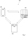
- Fig. 1 shows a schematic representation of an embodiment of a system 1 according to the invention comprising the devices 200, 300 and 400.
- the system is configured to carry out exemplary methods according to the invention.
- the device 200 is an exemplary mobile device 200, which in this case can be introduced into the treatment chamber of the dishwasher 300. Both the device 200 and the dishwasher 300 can each be a device according to the invention.
- the system 1 comprises, as a further device, the mobile device 400 in the form of a smartphone.
- the mobile device 400 can also carry out individual steps of exemplary methods according to the invention.
- the device 400 can also be a computer, a desktop computer or a portable computer, such as a laptop computer, a tablet computer, a personal digital assistant (PDA) or a wearable.
- PDA personal digital assistant
- the system can also comprise a server (in Fig. 1 not shown). It is also conceivable that the system 1 also comprises fewer or more than three devices. Likewise, the device 400 can represent the server. In this case, the device 400 is then operatively connected, for example, to at least one of the devices 200 or 300 via a communications network (e.g., the Internet).
- a communications network e.g., the Internet
- Each of the devices 200, 300, 400 may have a communication interface to communicate or exchange information with one or more of the other devices.
- Fig. 3 shows a flowchart 30 of an embodiment of a method according to the first aspect of the invention.
- the flowchart 30 can, for example, be used by the device 200 according to Fig. 1
- the flowchart 30 can be executed, for example, by the device 300 after Fig. 1
- the flowchart 30 can, for example, be executed both by the device 200 and Fig. 1 as well as from the device 300 to Fig. 1
- the flowchart 30 can be executed, for example, by the devices 200, 300 and 400 according to Fig. 1 be executed together.
- a first step 301 at least one item of acceleration information is acquired.
- the acquisition is carried out, for example, by means of an acceleration sensor (e.g., acceleration sensor(s) 215 according to Fig. 2 ), which is moved from the device 200 or 300 to Fig. 1
- the acceleration sensor is arranged in the treatment chamber of the dishwasher 300 during the detection.
- the device 200 is Fig. 1 comprises the acceleration sensor, it is therefore arranged at least temporarily during detection within the treatment chamber of the dishwasher 300.
- At least one piece of sensor information is acquired.
- the acquisition is carried out, for example, by means of a sensor (e.g., a temperature sensor and/or a timer 216 according to Fig. 2 ), which is moved from the device 200 or 300 to Fig. 1
- the temperature sensor and/or the timer are arranged in the treatment chamber of the dishwasher 300 during the detection. In the event that the device 200 is Fig. 1 the temperature sensor and/or the timer, these are therefore arranged at least temporarily during detection within the treatment chamber of the dishwasher 300.
- a third step 303 at least one item of status information is determined.
- the determination of the status information can, for example, be carried out by the device that also carried out steps 301 and 302.
- the determination of the status information in step 303 can be carried out by a device (e.g., device 400 according to Fig. 1 ) carried out by the device (e.g. device 200 according to Fig. 1 ) that performed steps 301 and 302.
- the status information determined in step 303 is output or initiated.
- the status information is output to a device 200, 300, or 400.
- the dishwasher 300 can, for example, carry out a cleaning of objects based on the status information, to name just one example.
- the status information is output to the device 400 (e.g., a user's mobile device)
- the user of the device 400 can be prompted to perform an action, for example, a predefined positioning and/or orientation of the device 200 according to Fig. 1 in the treatment room of the dishwasher 300 after Fig.1 to make.
- control information is determined based on the state information or on the output state information. This determined control information can in turn be output.
- this device 400 can also execute step 305.
- the determined control information can be transmitted, for example, from the device 400 to the device 200 and/or 300 after Fig. 1 be output so that the device 200 and/or 300 after Fig. 1 trigger an action corresponding to the control information, e.g., performing a dosage or starting a cleaning program, to name just a few non-limiting examples.
- the status information determined by device 200 can be output to device 300 and/or 400 accordingly.
- user profile information is created, for example based on the at least one piece of acceleration information acquired in step 301, the at least one piece of sensor information acquired in step 302, and the state information determined in step 303.
- the creation of the user profile information can be carried out, for example, by the device that carried out steps 301 and 302 of acquiring.
- the creation of the user profile information can be carried out, for example, by the device that carried out step 303 of determining the state information.
- steps 301 and 302 can be carried out by the device 200 or 300 after Fig. 1 be performed, and step 303 can be performed by the device 400 after Fig. 1
- all steps 301 to 303 can be performed by the device 200 or 300 Fig. 1 be performed.
- step of acquiring the at least one piece of acceleration information 301 and/or the step 302 of acquiring the at least one piece of sensor information can be performed simultaneously with step 303.
- step 303 of determining the state information is performed, while step 301 and step 302 are further executed by acquiring further acceleration information (step 301) and sensor information (step 302).
- step 303 or steps 303 to 304 and optionally steps 305 and/or 306 can be performed again, for example.
- Fig. 2 now shows a block diagram 20 of an embodiment of a device according to the second aspect of the invention for carrying out an embodiment of a method according to the first aspect of the invention.
- the block diagram 20 of Fig. 2 can be used as an example for both the Fig. 1 illustrated device 200, the illustrated dishwasher 300 or the illustrated mobile device 400 (or a part thereof).
- Processor 210 of device 20 is designed in particular as a microprocessor, microcontrol unit, microcontroller, digital signal processor (DSP), application-specific integrated circuit (ASIC) or field-programmable gate array (FPGA).
- DSP digital signal processor
- ASIC application-specific integrated circuit
- FPGA field-programmable gate array
- Processor 210 executes program instructions stored in program memory 212 and stores, for example, intermediate results or the like in working or main memory 211.
- program memory 212 is a non-volatile memory such as flash memory, magnetic memory, EEPROM (electrically erasable programmable read-only memory), and/or optical memory.
- Main memory 211 is, for example, a volatile or non-volatile memory, in particular a random access memory (RAM) such as static random access memory (SRAM), dynamic random access memory (DRAM), ferroelectric random access memory (FeRAM), and/or magnetic random access memory (MRAM).
- RAM random access memory
- SRAM static random access memory
- DRAM dynamic random access memory
- FeRAM ferroelectric random access memory
- MRAM magnetic random access memory
- Program memory 212 is preferably a local data storage medium permanently connected to device 20.
- Data storage mediums permanently connected to device 20 include, for example, hard disks built into device 20.
- the data storage medium may also be, for example, a data storage medium that can be detachably connected to device 20.
- Program memory 212 contains, for example, the operating system of device 20, which is at least partially loaded into main memory 211 and executed by processor 210 upon startup of device 20. In particular, upon startup of device 20, at least a portion of the core of the operating system is loaded into main memory 211 and executed by processor 210.
- the operating system enables, in particular, the use of the device 20 for data processing.
- it manages resources such as main memory 211 and program memory 212, communication interface 213, the optional input and output device 214, provides basic functions to other programs through programming interfaces, among other things, and controls the execution of programs.
- Processor 210 also controls the communication interface 213, which may, for example, be a network interface and may be configured as a network card, network module, and/or modem.
- the communication interface 213 is particularly configured to connect the device 20 to other devices (e.g., at least one of the devices 200, 300, and/or 400 according to Fig. 1 ), in particular via a (wireless) communication system, such as a network, and to communicate with them.
- the communication interface 213 For example, it can receive data (via the communication system) and forward it to processor 210 and/or receive data from processor 210 and send it (via the communication system).
- Examples of a communication system are a local area network (LAN), a wide area network (WAN), a wireless network (for example, according to the IEEE 802.11 standard, the Bluetooth (LE) standard and/or the NFC standard), a wired network, a cellular network, a telephone network and/or the Internet.
- LAN local area network
- WAN wide area network
- wireless network for example, according to the IEEE 802.11 standard, the Bluetooth (LE) standard and/or the NFC standard
- a wired network for example, a cellular network, a telephone network and/or the Internet.
- the Internet and/or other devices can be carried out via the communication interface 213.
- the devices 200, 300, 400 according to Fig. 1 can be communicated with the respective other devices 200, 300, 400 or the Internet, for example, by means of the respective communication interface 213.
- the at least one acceleration information cf. step 301 according to Fig. 3
- the at least one sensor information see step 302 after Fig. 3
- status information see step 303 or 304 after Fig. 3
- processor 210 can control at least one optional input/output device 214.
- Input/output device 214 is, for example, a keyboard, a mouse, a display unit, a microphone, a touch-sensitive display unit, a speaker, a reader, a drive, and/or a camera.
- Input/output device 214 can, for example, receive input from a user and forward it to processor 210 and/or receive and output information for the user from processor 210.
- the device 20 may comprise further components 215, 216.
- acceleration sensor(s) 215 can detect one or more acceleration information (see step 301 after Fig. 3 ).
- Sensor(s) 216 are, for example, a temperature sensor for detecting temperature information comprised by the at least one piece of sensor information, and/or a timer for detecting time information comprised by the at least one piece of sensor information, and/or optionally a brightness sensor for detecting brightness information comprised by the at least one piece of sensor information. Both the temperature information, the time information, and the brightness information can be comprised or represented by the at least one piece of sensor information (cf. step 302 according to Fig. 3 ).
- the solution according to the invention makes it possible to describe a process and program sequence of a dishwasher unambiguously (i.e. precisely or exactly), both for dishwashers used in households and for commercial dishwashers.
- a dosing device can carry out and/or control the method according to the first aspect of the present invention, which can be operated independently and can dispense a plurality of different preparations into the rinsing process.
- a device according to the second aspect of the invention e.g., a dosing device 200 according to Fig. 1 , comprises at least one acceleration sensor which is installed in the treatment room of a
- Dishwasher can be arranged.
- Such an acceleration sensor for example mounted on an electronic circuit board of the (autonomous) dosing device, is capable of fully detecting vibrations, shocks and/or mechanical events during a dishwashing process or cleaning program and making them accessible for interpretation.
- the cleaning program can be described unambiguously.
- the data determined by the sensors can, for example, be fed into machine learning applications, which can then be used to create pattern analyses, for example, and these can then be used to determine control data for the control and/or regulation of a device according to the second aspect of the invention, e.g. a dosing device or a dishwasher.
- Example A - Conventional rinsing process of a cleaning program carried out by a dishwasher Fig. 4 shows recorded information 415 from an acceleration sensor (415x, 415y, 415z) and a temperature sensor (416) in one plot.
- the x-axis represents the time in minutes.
- the y1-axis of the recorded acceleration information (415x, 415y, 415z) shows the oscillation of the acceleration sensor.
- the y2-axis shows the temperature (416) curve.
- the acceleration information (415x, 415y, 415z) and the sensor information indicative of the temperature (416) were recorded with a sampling rate of 10 Hz.
- the following process steps are described in the Fig. 4 to recognize: filling with water ("filling"), Pre-wash cold (no water exchange), main wash, water exchange, first rinse, final rinse, and drying.
- the acceleration sensor and the temperature sensor used to collect the information are controlled by a dosing device (e.g. device 200 according to Fig. 1 ) comprises that detachably in the treatment chamber of the dishwasher (e.g. device 300 according to Fig. 1 ).
- the dosing device was positioned upright in the lower basket of the treatment room and fixed between the plate holders of the lower basket.
- Fig. 4 shows the progress of the cleaning program on all axes of the acceleration sensor in combination with the temperature.
- the evaluation of the recorded (e.g., measured) acceleration information from the acceleration sensor in combination with the temperature allows a unique description of the cleaning program.
- a significant vibration in Fig. 4 (detected as oscillation) is detected by the acceleration sensor.
- the vibration is caused by the movement of the spray arms and the impact of water on the dosing device, as well as by the operation of the dishwasher's circulation pump.
- This allows the acceleration sensor to determine whether a washing process has started or not (in Fig. 4 as "start of cycle identification").”
- start of cycle identification the acceleration sensor to determine whether a washing process has started or not.
- Fig. 4 start of cycle identification
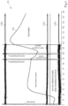
- Fig. 5 shows recorded information 515 from an acceleration sensor (515x, 515y, 515z) and a temperature sensor (516) in one plot.
- the x-axis represents time in minutes.
- the y1-axis of the recorded acceleration information curves (515x, 515y, 515z) shows the oscillation of the acceleration sensor.
- the y2-axis shows the temperature curve (516).
- the acceleration information (515x, 515y, 515z) and the sensor information indicative of the temperature (516) were recorded with a sampling rate of 10 Hz.
- the following process steps are described in the Fig. 5 to recognize: filling with water (“filling"), main cleaning cycle (“main wash”), water exchange (“water exchange”), first rinse (“1st rinse”), final rinse ("final rinse”).
- the signal oscillates on all axes with varying deflections.
- the degree of deflection depends on the positioning of the Dosing device and thus the acceleration sensor.
- the acceleration sensor is mounted upright on a circuit board enclosed by the dosing device. With a defined (ie fixed) position of the dosing device, defined axis directions result.
- the dosing device and therefore also the circuit board are positioned parallel to the side walls of the dishwasher's treatment chamber. This means that the x-axis points towards the rear wall and door, the y-axis towards the lid and floor, and the z-axis towards the left and right side walls.
- the strongest oscillations compared to the other axes can clearly be seen on the z-axis. These oscillations result from the spray jet hitting the side surfaces of the dosing device and thus cause the acceleration sensor to move. This means that whenever stronger signals occur on the z-axis compared to the other axes, the dosing device is positioned parallel to the side wall. If the signal is strongest on the x-axis, the device is positioned parallel to the door. This means that the position of the dosing device in the dishwasher can be determined unambiguously. This information can be used, for example, to give a user instructions on how to position the dosing device or to provide advice on how to solve malfunctions that may occur.
- Example B - Detecting a water change during a cleaning program performed by a dishwasher A self-contained measuring and/or dosing system, e.g. a dosing device (e.g. device 200 according to Fig. 1 ), should be able to identify individual program steps during a running cleaning program in order to, for example, ensure individual preparation of cleaning agent. This is particularly important for a self-contained, automatic dosing device because, depending on the timing of the dishwashing process, dosing processes must be triggered to guarantee satisfactory performance for a user. Characteristic of every dishwashing process are water changes, in which at least a part, usually the entire volume is replaced with fresh, usually cold water.
- Such water changes usually take place after a pre-wash cycle or pre-cleaning cycle, after a main wash cycle or main cleaning cycle and after an intermediate rinse cycle as part of the dishwasher's cleaning program (e.g. device 300 after Fig. 1 ). They are characterized by a pumping process, in which the water from the previous wash cycle is removed using a wastewater pump, and a filling process, in which fresh water flows into the dishwasher. During these processes, the spray arm rotation is stopped.
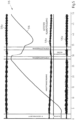
- Fig. 6 shows recorded information 615 from an acceleration sensor (615y) and a temperature sensor (616) in one plot.
- the x-axis represents time in minutes.
- the y1-axis of the recorded acceleration information (615y) shows the oscillation of the acceleration sensor.
- the y2-axis shows the temperature (616) curve.
- the acceleration information (615y) and the sensor information indicative of the temperature (616) were recorded at a sampling rate of 10 Hz.
- the following process steps are according to the designations in the Fig. 6 to recognize: pre-wash (“pre-wash cold (no water exchange)"), main cleaning cycle (“main wash”), dry pumping ("drain pump”), first rinse (“1st rinse”), final rinse (“final rinse”), and drying process (“drying”).
- Fig. 6 shows several water changes on the y-axis of a curve represented by recorded acceleration sensor information.
- the y-axis is particularly sensitive to the processes because its orientation points, among other things, to the machine floor.
- the acceleration sensor first registers the vibration of the wastewater pump (in Fig. 6 marked with “drain pump”). This is followed by a rest period without spray arm movement, during which the water flows in.
- the combination of the two processes clearly describes the water change. If the signal from the acceleration sensor is linked to a signal as temperature information recorded by a temperature sensor, the process can be described uniquely. This is because when cool water flows into the machine, the interior temperature drops significantly after the circulation pump restarts (in Fig. 6 marked “first rinse” or at the beginning of the section “final rinse”).
- the dosing device can, for example, start a timer that can be used to monitor when movement is detected again on the axes of the acceleration sensor, which detects movement of the acceleration sensor on these axes. If this occurs within a specified time window and the temperature drops within a specified time window, the water change is reliably detected.
- the reliable detection of water changes is very important for the description of the entire washing process or a cleaning program carried out by the dishwasher, because it must be clearly distinguished whether the subsequent rinse cycle of the cleaning program is a cleaning cycle, an intermediate rinse cycle or a final rinse cycle.
- Example C Detecting a drying cycle of a cleaning program performed by a dishwasher: After the final rinse cycle has been completed (see above embodiment B), the dishwasher (e.g. device 300 after Fig. 1 ) into the drying phase. In the drying phase, the dishes dry due to the stored energy from the previous final rinse (according to the heat capacities of the different dish materials). The drying phase is characterized primarily by the fact that the spray arms are no longer moving. Similar to the filling example A, the drying phase is a distinctly "silent noise" phase, since, for example, no water is circulated. This allows the drying phase to be clearly distinguished from the previous final rinse cycle on all axes of the acceleration sensor by comparing the oscillations (see Fig. 6 and Fig. 7 ).
- Fig. 7 shows recorded information 715 from an acceleration sensor (715x, 715y, 715z) and a temperature sensor (716) in one plot.
- the x-axis represents the time in minutes.
- the y1-axis of the recorded acceleration information (715x, 715y, 715z) shows the oscillation of the acceleration sensor.
- the y2-axis shows the temperature (716) curve.
- the acceleration information (715x, 715y, 715z) and the sensor information indicative of the temperature (716) were recorded with a sampling rate of 10 Hz.
- main cleaning cycle (“main wash")
- water exchange water exchange
- first rinse 1st rinse
- final rinse final rinse
- drying process drying process
- the dishwasher stops the spray arm rotation between minutes 62 and 63.
- the water is pumped out and the dishes dry using its own heat.
- the waiting time now begins, during which the dishwasher is supposedly inactive.
- a self-sufficient dosing device e.g., device 200 after Fig. 1 , for example, can start a timer at the beginning of the waiting period. If the timer exceeds a specified value and the acceleration sensor no longer detects any movement on any axes, it can be clearly assumed that the drying phase has begun.
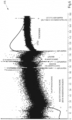
- Fig. 8 shows recorded information 815 from an acceleration sensor (815z) and a temperature sensor (816) in one plot.
- the x-axis represents the time in minutes.
- the y1-axis of the recorded acceleration information (815z) shows the oscillation of the acceleration sensor.
- the y2-axis shows the temperature (816) curve.
- the acceleration information (815z) and the sensor information indicative of the temperature (816) were recorded with a sampling rate of 10 Hz. The following process steps are described in the Fig.
- the drying process is, for example, thermally activated drying, also known as the zeolite drying process.
- thermally activated drying also known as the zeolite drying process.
- the dishes are not heated during the final rinse; in fact, the dishes can even cool slightly (see [Fig. Fig. 8 ).
- the transition to the drying cycle can now be determined again by level comparison.
- the timer in combination with the movement signal would detect oscillation on all axes again, because in the so-called zeolite drying process a fan then starts up, which conveys the moist air to the zeolite adsorber. There the water contained in the air is absorbed by the zeolite.
- Example D - Detecting the end of a cleaning program performed by a dishwasher (“End-of-Cycle Detection"): The detection of the true end of a rinse cycle is for a self-sufficient dosing device (e.g. device 200 according to Fig. 1 ) is not possible without further ado.
- the end of the oscillation phase initially means the start of the drying phase of a dishwashing machine (e.g. device 300 after Fig. 1 ) cleaning program and has nothing to do with the absolute end of the rinse cycle.
- Fig. 9 shows recorded information 915 from an acceleration sensor (915x, 915y, 915z) and a temperature sensor (916) in one plot.
- the x-axis represents time in minutes.
- the y1-axis of the recorded acceleration information (915x, 915y, 915z) shows the oscillation of the acceleration sensor.
- the y2-axis shows the temperature (916) curve.
- the acceleration information (915x, 915y, 915z) and the sensor information indicative of the temperature (916) were recorded with a sampling rate of 10 Hz. The following process steps are described in the Fig.
- Fig. 10 shows recorded information 1015 from an acceleration sensor (1015x, 1015y, 1015z) and a temperature sensor (1016) in one plot.
- the x-axis represents the time in minutes.
- the y1-axis of the recorded acceleration information (1015x, 1015y, 1015z) shows the oscillation of the acceleration sensor.
- the y2-axis shows the temperature (1016) curve.
- the acceleration information (1015x, 1015y, 1015z) and the sensor information indicative of the temperature (1016) were recorded with a sampling rate of 10 Hz.
- the following process steps are described in the Fig. 10 to recognize: pre-wash, main cleaning cycle ("main wash”), water exchange (“water exchange”), first rinse (“1st rinse”), final rinse (“final rinse”), drying process (“drying”), and final pumping ("final pumping”).
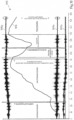
- Fig. 11 shows recorded information 1115 from an acceleration sensor (1115x, 1115y, 1115z) and a temperature sensor (1116) in one plot.
- the x-axis represents the time in minutes.
- the y1-axis of the recorded acceleration information curves (1115x, 1115y, 1115z) shows the oscillation of the acceleration sensor.
- the y2-axis shows the temperature curve (1116).
- the acceleration information (1115x, 1115y, 1115z) and the sensor information indicative of the temperature (1116) were recorded with a sampling rate of 10 Hz.
- the following process steps are described in the Fig. 11 to recognize: filling with water (“filling"), main cleaning cycle (“main wash”), water exchange (“water exchange”), first rinse (“1st rinse”), final rinse ("final rinse”), and drying process (“drying”).
- the end of the wash cycle is typically notified to the consumer by an acoustic signal or a display.
- a dosing device located in the dishwasher's treatment chamber does not have this option.
- Many dishwasher programs conclude the drying phase with one or more pumping steps to remove condensate and residual detergent.
- the operation of the wastewater pump causes sufficient vibrations that can be detected by an acceleration sensor (see Figure 1).
- acceleration information and recorded time measurement values, e.g., time information recorded with a timer, to identify the end of a cleaning program by means of the acceleration information and time information recorded during a drying process of the cleaning program.
- a dosing device e.g. device 200 according to Fig. 1
- sensor equipment in particular an acceleration sensor included therein
- All sensory data can be stored in a database, for example, and then evaluated. Storage and evaluation can take place locally, but is preferably done in a remote system (e.g. server or server cloud).
- the data can also optionally be fed into a machine learning tool, for example to recognize data patterns.
- the data patterns can be used, for example, to give the user feedback on their application, to point out problems, or to control a dosing device.
- a user of a (self-sufficient) dosing device selects a specific cleaning program on his dishwasher, but always the same one (as in Fig. 4 (shown in the figure).
- the dosing device monitors the progress of the cleaning program.
- the dosing device would dispense detergent upon sensing, for example, a spray arm movement and a temperature rise.
- the dosing device could learn to dispense earlier because the cleaning program pattern is recognized early on. This significantly extends the cleaning time with the chemicals present, thus achieving improved cleaning results.
- a user of such a (self-contained) dosing device uses a cleaning program with a long cleaning duration during the week and always uses cleaning programs with short cleaning durations on the weekends.
- a user profile can be created and, for example, the amount of cleaning agent to be dispensed can be adjusted to the respective cleaning programs during the week and on the weekend.
Landscapes
- Washing And Drying Of Tableware (AREA)
Claims (10)
- Procédé (30), comprenant :- la détection d'au moins une information d'accélération indiquant une évolution de valeurs d'accélération mesurées, dans lequel l'au moins une information d'accélération est détectée par au moins un capteur d'accélération dans un espace de traitement d'un lave-vaisselle (300), dans lequel le capteur d'accélération fait partie d'un appareil de dosage séparé dans l'espace de traitement du lave-vaisselle ;- la détermination d'une information d'état indiquant une étape de processus dans un programme de nettoyage réalisé par le lave-vaisselle, dans lequel l'information d'état est déterminée sur la base de l'au moins une information d'accélération ;- la détection d'au moins une information de capteur indiquant une évolution d'une température et/ou d'un temps,
dans lequel l'information d'état est en outre déterminée sur la base de l'au moins une information de capteur ;- l'émission ou l'incitation à l'émission de l'information d'état déterminée,- dans lequel l'au moins une information d'accélération est détectée par rapport à une orientation et/ou un positionnement prédéfinis de l'au moins un capteur d'accélération dans l'espace de traitement du lave-vaisselle,
dans lequel l'au moins une information d'accélération représente un signal dans la direction de chacun parmi deux ou trois degrés de liberté,- dans lequel l'orientation prédéfinie et/ou le positionnement prédéfini de l'au moins un capteur d'accélération dans l'espace de traitement du lave-vaisselle sont déterminés sur la base d'une comparaison entre les signaux dans la direction de tous les degrés de liberté représentés par l'au moins une information d'accélération. - Procédé selon la revendication 1, comprenant en outre :- la détermination d'une information de commande sur la base au moins en partie de l'information d'état, dans lequel l'information de commande amène l'appareil de dosage mobile à réaliser un dosage de produit de nettoyage et/ou d'entretien défini conformément à l'information de commande.
- Procédé selon l'une des revendications précédentes, dans lequel l'information d'état représente une ou plusieurs étapes de processus i) à xi) du programme de nettoyage :i) démarrage du programme de nettoyage ;ii) réalisation d'un remplissage avec de l'eau pendant le programme de nettoyage ;iii) réalisation d'un changement d'eau pendant le programme de nettoyage ;iv) réalisation d'un prérinçage pendant le programme de nettoyage ;v) réalisation d'un cycle de nettoyage principal pendant le programme de nettoyage ;vi) réalisation d'un premier rinçage, en particulier d'un rinçage intermédiaire, pendant le programme de nettoyage ;vii) réalisation d'autres étapes de rinçage, en, particulier d'autres rinçages intermédiaires, pendant le programme de nettoyage ;viii) réalisation d'un rinçage final pendant le programme de nettoyage ;ix) réalisation d'un processus de séchage pendant le programme de nettoyage ;x) réalisation d'un processus de séchage alternatif, en particulier actif avec des zéolithes, pendant le programme de nettoyage ; etxi) fin du programme de nettoyage.
- Procédé selon l'une des revendications précédentes, dans lequel l'information d'accélération et/ou l'au moins une information de capteur sont respectivement détectées sur une durée prédéfinie.
- Procédé selon l'une des revendications précédentes, dans lequel l'au moins un capteur d'accélération est disposé à l'intérieur de l'espace de traitement du lave-vaisselle, en particulier sur ou dans un panier inférieur destiné à recevoir des objets à nettoyer, de sorte que le positionnement prédéfini de l'au moins un capteur d'accélération est présent à l'intérieur de l'espace de traitement du lave-vaisselle.
- Procédé selon la revendication 1, dans lequel la détermination de l'information d'état est réalisée séparément pour tous les deux ou trois degrés de liberté.
- Procédé selon l'une des revendications 1 à 6, dans lequel la détermination de l'information d'état est en outre effectuée sur la base d'une ou de plusieurs des étapes suivantes :- un niveau de bruit représenté par l'au moins une information d'accélération à deux instants de détection ;- une évolution représentée par l'au moins une information d'accélération en comparaison avec une évolution représentée par la température de l'information de capteur ; et- une évolution représentée par l'au moins une information d'accélération en comparaison avec une évolution représentée par le temps de l'information de capteur.
- Procédé selon l'une des revendications 1 à 7, comprenant en outre :- la création d'une information de profil utilisateur sur la base au moins en partie de l'au moins une information d'accélération détectée, et/ou de l'au moins une information de capteur, dans lequel l'information d'état est en outre déterminée sur la base de l'information de profil utilisateur.
- Dispositif configuré pour commander le procédé selon l'une des revendications 1 à 8.
- Programme informatique, comprenant des instructions de programme qui amènent un processeur à mettre en œuvre et/ou à commander le procédé selon l'une des revendications 1 à 8 lorsque le programme informatique est exécuté sur le processeur.
Applications Claiming Priority (2)
| Application Number | Priority Date | Filing Date | Title |
|---|---|---|---|
| DE102018210496.4A DE102018210496A1 (de) | 2018-06-27 | 2018-06-27 | Überwachung eines Reinigungsprogramms von einer Geschirrspülmaschine |
| PCT/EP2019/066953 WO2020002400A1 (fr) | 2018-06-27 | 2019-06-26 | Surveillance d'un programme de nettoyage d'un lave-vaisselle |
Publications (2)
| Publication Number | Publication Date |
|---|---|
| EP3813624A1 EP3813624A1 (fr) | 2021-05-05 |
| EP3813624B1 true EP3813624B1 (fr) | 2025-06-04 |
Family
ID=67137929
Family Applications (1)
| Application Number | Title | Priority Date | Filing Date |
|---|---|---|---|
| EP19734745.3A Active EP3813624B1 (fr) | 2018-06-27 | 2019-06-26 | Surveillance d'un programme de nettoyage d'un lave-vaisselle |
Country Status (7)
| Country | Link |
|---|---|
| US (1) | US12016504B2 (fr) |
| EP (1) | EP3813624B1 (fr) |
| CN (1) | CN112312817B (fr) |
| DE (1) | DE102018210496A1 (fr) |
| ES (1) | ES3034095T3 (fr) |
| PL (1) | PL3813624T3 (fr) |
| WO (1) | WO2020002400A1 (fr) |
Families Citing this family (1)
| Publication number | Priority date | Publication date | Assignee | Title |
|---|---|---|---|---|
| US20230281439A1 (en) * | 2022-03-07 | 2023-09-07 | Applied Materials, Inc. | Synthetic time series data associated with processing equipment |
Family Cites Families (18)
| Publication number | Priority date | Publication date | Assignee | Title |
|---|---|---|---|---|
| US6654975B2 (en) * | 2001-08-24 | 2003-12-02 | Maytag Corporation | Appliance incorporating leveling display system |
| DE10204455A1 (de) * | 2002-02-05 | 2003-08-21 | Miele & Cie | Verfahren zur Beeinflussung und/oder Steuerung des Programmlaufs eines wasserführenden Haushaltgerätes, insbesondere Geschirrspülmaschine, sowie Geschirrspülmaschine zur Durchführung des Verfahrens |
| DE102007042863A1 (de) * | 2007-09-10 | 2009-03-12 | Henkel Ag & Co. Kgaa | Dosiersystem zur Abgabe von fließ- oder streufähigen Zubereitungen |
| ES2534425T3 (es) * | 2008-07-15 | 2015-04-22 | Henkel Ag & Co. Kgaa | Sistema de dosificación con soporte de componentes |
| DE102008036586A1 (de) * | 2008-08-06 | 2010-02-11 | Henkel Ag & Co. Kgaa | Haushaltsmaschine |
| DE102008045087A1 (de) * | 2008-08-29 | 2010-03-04 | Lg Electronics Inc. | Geschirrspülmaschine |
| ITRN20110080A1 (it) * | 2011-11-29 | 2013-05-30 | Indesit Co Spa | Lavastoviglie. |
| US9359712B2 (en) * | 2012-04-04 | 2016-06-07 | Whirlpool Corporation | Apparatus and method for controlling the energy usage of an appliance |
| EP2662014A1 (fr) * | 2012-05-11 | 2013-11-13 | Electrolux Home Products Corporation N.V. | Procédé de détection de charge dans un panier de lave-vaisselle |
| EP2732748B1 (fr) * | 2012-11-20 | 2017-01-04 | Premark FEG L.L.C. | Système de détection de panne de moteur de pompe de lave-vaisselle et procédé associé |
| DE102012222196A1 (de) * | 2012-12-04 | 2014-01-02 | E.G.O. Elektro-Gerätebau GmbH | Sensoreinrichtung und Elektrohaushaltsgerät mit einer solchen Sensoreinrichtung |
| DE102013218468A1 (de) * | 2013-09-16 | 2015-03-19 | BSH Bosch und Siemens Hausgeräte GmbH | System, Nachrüstmodul und Verfahren zum überwachen eines aktuellen Betriebszustands eines programmgesteuerten Haushaltsgeräts |
| DE102013220568A1 (de) * | 2013-10-11 | 2015-04-16 | Robert Bosch Gmbh | Vorrichtung zur Messung von Zustandsgrößen eines Haushaltsgerätevorgangs und zur Übertragung der Zustandsgrößen, Haushaltsgerät und Verfahren zur Messung von Zustandsgrößen eines Haushaltsgerätevorgangs |
| US9706897B2 (en) * | 2014-11-20 | 2017-07-18 | The Procter & Gamble Company | Personalized cleaning composition dispensing device |
| CN106033091B (zh) * | 2015-03-11 | 2022-04-29 | 中芯国际集成电路制造(上海)有限公司 | 一种mems加速度传感器及其制备方法、电子装置 |
| DE102016225812A1 (de) * | 2016-12-21 | 2018-06-21 | Henkel Ag & Co. Kgaa | Vorrichtung und Verfahren zur Dosierung von Reinigungsmitteln |
| GB201707438D0 (en) * | 2017-05-09 | 2017-06-21 | Howden Joinery Group Plc | Detecting appliance conformity |
| DE102018210497A1 (de) * | 2018-06-27 | 2020-01-02 | Henkel Ag & Co. Kgaa | Überwachung einer Be- und/oder Entladung von Geschirrspülmaschinen |
-
2018
- 2018-06-27 DE DE102018210496.4A patent/DE102018210496A1/de not_active Withdrawn
-
2019
- 2019-06-26 CN CN201980043192.5A patent/CN112312817B/zh active Active
- 2019-06-26 US US17/044,248 patent/US12016504B2/en active Active
- 2019-06-26 ES ES19734745T patent/ES3034095T3/es active Active
- 2019-06-26 EP EP19734745.3A patent/EP3813624B1/fr active Active
- 2019-06-26 WO PCT/EP2019/066953 patent/WO2020002400A1/fr not_active Ceased
- 2019-06-26 PL PL19734745.3T patent/PL3813624T3/pl unknown
Also Published As
| Publication number | Publication date |
|---|---|
| PL3813624T3 (pl) | 2025-11-17 |
| CN112312817B (zh) | 2025-01-24 |
| CN112312817A (zh) | 2021-02-02 |
| EP3813624A1 (fr) | 2021-05-05 |
| WO2020002400A1 (fr) | 2020-01-02 |
| US20210204791A1 (en) | 2021-07-08 |
| DE102018210496A1 (de) | 2020-01-02 |
| ES3034095T3 (en) | 2025-08-12 |
| US12016504B2 (en) | 2024-06-25 |
Similar Documents
| Publication | Publication Date | Title |
|---|---|---|
| EP3813626A1 (fr) | Surveillance d'un chargement et/ou déchargement de lave-vaisselles | |
| EP3485082B1 (fr) | Procédé de surveillance du stockage d'un produit de nettoyage et dispositif correspondant | |
| EP3376931B1 (fr) | Procédé pour faire fonctionner un lave-vaisselle et lave-vaisselle correspondant | |
| EP3485077B1 (fr) | Procédé et dispositif de surveillance de réserve | |
| WO2020089198A1 (fr) | Procédé et dispositif pour un appareil electroménager transportant l'air | |
| DE102018203586A1 (de) | Vorrichtung mit Ausgabemodul und/oder Sensormodul | |
| EP3558083A1 (fr) | Procédé de dosage de produits de lavage | |
| EP3160321B1 (fr) | Appareil ménager utilisant de l'eau | |
| EP3762528A1 (fr) | Détermination d'un état d'un appareil électroménager | |
| EP3813624B1 (fr) | Surveillance d'un programme de nettoyage d'un lave-vaisselle | |
| DE102016225812A1 (de) | Vorrichtung und Verfahren zur Dosierung von Reinigungsmitteln | |
| WO2018114362A1 (fr) | Procédé de dosage de produits de lavage | |
| EP4157054B1 (fr) | Système avec lave-vaisselle, procédé et produit-programme informatique | |
| DE112022000130T5 (de) | Reinigungsverfahren und reinigungsvorrichtung für eine geschirrspülmaschine, und geschirrspülmaschine | |
| EP3559328B1 (fr) | Détermination de paramètres de traitement au moyen d'une information géométrique relative à un textile | |
| EP3729394A1 (fr) | Commande et/ou réglage d'appareils ménagers | |
| EP3457905B1 (fr) | Commande d'un appareil électroménager | |
| EP3762530B1 (fr) | Dispositif à utiliser dans un appareil de traitement des textiles domestiques et utilisation d'un capteur | |
| DE102018109332A1 (de) | Verfahren und Vorrichtung zum Betreiben eines Haushaltgeräts und Haushaltgerät mit einer Vorrichtung | |
| DE102010062924A1 (de) | Haushaltsgerät und Verfahren zum Betreiben des Haushaltsgeräts |
Legal Events
| Date | Code | Title | Description |
|---|---|---|---|
| STAA | Information on the status of an ep patent application or granted ep patent |
Free format text: STATUS: UNKNOWN |
|
| STAA | Information on the status of an ep patent application or granted ep patent |
Free format text: STATUS: THE INTERNATIONAL PUBLICATION HAS BEEN MADE |
|
| PUAI | Public reference made under article 153(3) epc to a published international application that has entered the european phase |
Free format text: ORIGINAL CODE: 0009012 |
|
| STAA | Information on the status of an ep patent application or granted ep patent |
Free format text: STATUS: REQUEST FOR EXAMINATION WAS MADE |
|
| 17P | Request for examination filed |
Effective date: 20210113 |
|
| AK | Designated contracting states |
Kind code of ref document: A1 Designated state(s): AL AT BE BG CH CY CZ DE DK EE ES FI FR GB GR HR HU IE IS IT LI LT LU LV MC MK MT NL NO PL PT RO RS SE SI SK SM TR |
|
| DAV | Request for validation of the european patent (deleted) | ||
| DAX | Request for extension of the european patent (deleted) | ||
| STAA | Information on the status of an ep patent application or granted ep patent |
Free format text: STATUS: EXAMINATION IS IN PROGRESS |
|
| 17Q | First examination report despatched |
Effective date: 20230217 |
|
| P01 | Opt-out of the competence of the unified patent court (upc) registered |
Effective date: 20230530 |
|
| GRAP | Despatch of communication of intention to grant a patent |
Free format text: ORIGINAL CODE: EPIDOSNIGR1 |
|
| STAA | Information on the status of an ep patent application or granted ep patent |
Free format text: STATUS: GRANT OF PATENT IS INTENDED |
|
| INTG | Intention to grant announced |
Effective date: 20250211 |
|
| GRAS | Grant fee paid |
Free format text: ORIGINAL CODE: EPIDOSNIGR3 |
|
| GRAA | (expected) grant |
Free format text: ORIGINAL CODE: 0009210 |
|
| STAA | Information on the status of an ep patent application or granted ep patent |
Free format text: STATUS: THE PATENT HAS BEEN GRANTED |
|
| AK | Designated contracting states |
Kind code of ref document: B1 Designated state(s): AL AT BE BG CH CY CZ DE DK EE ES FI FR GB GR HR HU IE IS IT LI LT LU LV MC MK MT NL NO PL PT RO RS SE SI SK SM TR |
|
| REG | Reference to a national code |
Ref country code: GB Ref legal event code: FG4D Free format text: NOT ENGLISH |
|
| REG | Reference to a national code |
Ref country code: CH Ref legal event code: EP |
|
| REG | Reference to a national code |
Ref country code: DE Ref legal event code: R096 Ref document number: 502019013409 Country of ref document: DE |
|
| REG | Reference to a national code |
Ref country code: IE Ref legal event code: FG4D Free format text: LANGUAGE OF EP DOCUMENT: GERMAN |
|
| PGFP | Annual fee paid to national office [announced via postgrant information from national office to epo] |
Ref country code: DE Payment date: 20250618 Year of fee payment: 7 |
|
| REG | Reference to a national code |
Ref country code: ES Ref legal event code: FG2A Ref document number: 3034095 Country of ref document: ES Kind code of ref document: T3 Effective date: 20250812 |
|
| REG | Reference to a national code |
Ref country code: NL Ref legal event code: MP Effective date: 20250604 |
|
| PG25 | Lapsed in a contracting state [announced via postgrant information from national office to epo] |
Ref country code: FI Free format text: LAPSE BECAUSE OF FAILURE TO SUBMIT A TRANSLATION OF THE DESCRIPTION OR TO PAY THE FEE WITHIN THE PRESCRIBED TIME-LIMIT Effective date: 20250604 |
|
| PGFP | Annual fee paid to national office [announced via postgrant information from national office to epo] |
Ref country code: ES Payment date: 20250731 Year of fee payment: 7 |
|
| REG | Reference to a national code |
Ref country code: LT Ref legal event code: MG9D |
|
| PG25 | Lapsed in a contracting state [announced via postgrant information from national office to epo] |
Ref country code: NO Free format text: LAPSE BECAUSE OF FAILURE TO SUBMIT A TRANSLATION OF THE DESCRIPTION OR TO PAY THE FEE WITHIN THE PRESCRIBED TIME-LIMIT Effective date: 20250904 Ref country code: GR Free format text: LAPSE BECAUSE OF FAILURE TO SUBMIT A TRANSLATION OF THE DESCRIPTION OR TO PAY THE FEE WITHIN THE PRESCRIBED TIME-LIMIT Effective date: 20250905 |
|
| PGFP | Annual fee paid to national office [announced via postgrant information from national office to epo] |
Ref country code: IT Payment date: 20250929 Year of fee payment: 7 Ref country code: TR Payment date: 20250825 Year of fee payment: 7 |
|
| PG25 | Lapsed in a contracting state [announced via postgrant information from national office to epo] |
Ref country code: BG Free format text: LAPSE BECAUSE OF FAILURE TO SUBMIT A TRANSLATION OF THE DESCRIPTION OR TO PAY THE FEE WITHIN THE PRESCRIBED TIME-LIMIT Effective date: 20250604 |
|
| PGFP | Annual fee paid to national office [announced via postgrant information from national office to epo] |
Ref country code: GB Payment date: 20250722 Year of fee payment: 7 |
|
| PG25 | Lapsed in a contracting state [announced via postgrant information from national office to epo] |
Ref country code: HR Free format text: LAPSE BECAUSE OF FAILURE TO SUBMIT A TRANSLATION OF THE DESCRIPTION OR TO PAY THE FEE WITHIN THE PRESCRIBED TIME-LIMIT Effective date: 20250604 |
|
| PGFP | Annual fee paid to national office [announced via postgrant information from national office to epo] |
Ref country code: FR Payment date: 20250730 Year of fee payment: 7 |
|
| PG25 | Lapsed in a contracting state [announced via postgrant information from national office to epo] |
Ref country code: RS Free format text: LAPSE BECAUSE OF FAILURE TO SUBMIT A TRANSLATION OF THE DESCRIPTION OR TO PAY THE FEE WITHIN THE PRESCRIBED TIME-LIMIT Effective date: 20250904 |
|
| PG25 | Lapsed in a contracting state [announced via postgrant information from national office to epo] |
Ref country code: LV Free format text: LAPSE BECAUSE OF FAILURE TO SUBMIT A TRANSLATION OF THE DESCRIPTION OR TO PAY THE FEE WITHIN THE PRESCRIBED TIME-LIMIT Effective date: 20250604 |
|
| PG25 | Lapsed in a contracting state [announced via postgrant information from national office to epo] |
Ref country code: NL Free format text: LAPSE BECAUSE OF FAILURE TO SUBMIT A TRANSLATION OF THE DESCRIPTION OR TO PAY THE FEE WITHIN THE PRESCRIBED TIME-LIMIT Effective date: 20250604 |
|
| PG25 | Lapsed in a contracting state [announced via postgrant information from national office to epo] |
Ref country code: PT Free format text: LAPSE BECAUSE OF FAILURE TO SUBMIT A TRANSLATION OF THE DESCRIPTION OR TO PAY THE FEE WITHIN THE PRESCRIBED TIME-LIMIT Effective date: 20251006 |
|
| PG25 | Lapsed in a contracting state [announced via postgrant information from national office to epo] |
Ref country code: IS Free format text: LAPSE BECAUSE OF FAILURE TO SUBMIT A TRANSLATION OF THE DESCRIPTION OR TO PAY THE FEE WITHIN THE PRESCRIBED TIME-LIMIT Effective date: 20251004 |
|
| PG25 | Lapsed in a contracting state [announced via postgrant information from national office to epo] |
Ref country code: SM Free format text: LAPSE BECAUSE OF FAILURE TO SUBMIT A TRANSLATION OF THE DESCRIPTION OR TO PAY THE FEE WITHIN THE PRESCRIBED TIME-LIMIT Effective date: 20250604 |
|
| PG25 | Lapsed in a contracting state [announced via postgrant information from national office to epo] |
Ref country code: CZ Free format text: LAPSE BECAUSE OF FAILURE TO SUBMIT A TRANSLATION OF THE DESCRIPTION OR TO PAY THE FEE WITHIN THE PRESCRIBED TIME-LIMIT Effective date: 20250604 |
|
| PGFP | Annual fee paid to national office [announced via postgrant information from national office to epo] |
Ref country code: PL Payment date: 20250724 Year of fee payment: 7 |
|
| PG25 | Lapsed in a contracting state [announced via postgrant information from national office to epo] |
Ref country code: EE Free format text: LAPSE BECAUSE OF FAILURE TO SUBMIT A TRANSLATION OF THE DESCRIPTION OR TO PAY THE FEE WITHIN THE PRESCRIBED TIME-LIMIT Effective date: 20250604 |
|
| PG25 | Lapsed in a contracting state [announced via postgrant information from national office to epo] |
Ref country code: SK Free format text: LAPSE BECAUSE OF FAILURE TO SUBMIT A TRANSLATION OF THE DESCRIPTION OR TO PAY THE FEE WITHIN THE PRESCRIBED TIME-LIMIT Effective date: 20250604 Ref country code: RO Free format text: LAPSE BECAUSE OF FAILURE TO SUBMIT A TRANSLATION OF THE DESCRIPTION OR TO PAY THE FEE WITHIN THE PRESCRIBED TIME-LIMIT Effective date: 20250604 |
|
| REG | Reference to a national code |
Ref country code: CH Ref legal event code: H13 Free format text: ST27 STATUS EVENT CODE: U-0-0-H10-H13 (AS PROVIDED BY THE NATIONAL OFFICE) Effective date: 20260127 |
|
| PG25 | Lapsed in a contracting state [announced via postgrant information from national office to epo] |
Ref country code: LU Free format text: LAPSE BECAUSE OF NON-PAYMENT OF DUE FEES Effective date: 20250626 |
|
| REG | Reference to a national code |
Ref country code: BE Ref legal event code: MM Effective date: 20250630 |
|
| REG | Reference to a national code |
Ref country code: DE Ref legal event code: R097 Ref document number: 502019013409 Country of ref document: DE |
|
| PG25 | Lapsed in a contracting state [announced via postgrant information from national office to epo] |
Ref country code: MC Free format text: LAPSE BECAUSE OF FAILURE TO SUBMIT A TRANSLATION OF THE DESCRIPTION OR TO PAY THE FEE WITHIN THE PRESCRIBED TIME-LIMIT Effective date: 20250604 |
|
| PLBE | No opposition filed within time limit |
Free format text: ORIGINAL CODE: 0009261 |
|
| STAA | Information on the status of an ep patent application or granted ep patent |
Free format text: STATUS: NO OPPOSITION FILED WITHIN TIME LIMIT |
|
| PG25 | Lapsed in a contracting state [announced via postgrant information from national office to epo] |
Ref country code: IE Free format text: LAPSE BECAUSE OF NON-PAYMENT OF DUE FEES Effective date: 20250626 Ref country code: DK Free format text: LAPSE BECAUSE OF FAILURE TO SUBMIT A TRANSLATION OF THE DESCRIPTION OR TO PAY THE FEE WITHIN THE PRESCRIBED TIME-LIMIT Effective date: 20250604 |
|
| PG25 | Lapsed in a contracting state [announced via postgrant information from national office to epo] |
Ref country code: BE Free format text: LAPSE BECAUSE OF NON-PAYMENT OF DUE FEES Effective date: 20250630 |
|
| REG | Reference to a national code |
Ref country code: CH Ref legal event code: L10 Free format text: ST27 STATUS EVENT CODE: U-0-0-L10-L00 (AS PROVIDED BY THE NATIONAL OFFICE) Effective date: 20260416 |