EP3813232B1 - Moteur dépourvu de partie centrale de type colonne - Google Patents
Moteur dépourvu de partie centrale de type colonne Download PDFInfo
- Publication number
- EP3813232B1 EP3813232B1 EP20193042.7A EP20193042A EP3813232B1 EP 3813232 B1 EP3813232 B1 EP 3813232B1 EP 20193042 A EP20193042 A EP 20193042A EP 3813232 B1 EP3813232 B1 EP 3813232B1
- Authority
- EP
- European Patent Office
- Prior art keywords
- rotor
- heat dissipation
- permanent magnets
- motor
- dissipation fan
- Prior art date
- Legal status (The legal status is an assumption and is not a legal conclusion. Google has not performed a legal analysis and makes no representation as to the accuracy of the status listed.)
- Active
Links
Images

Classifications
-
- H—ELECTRICITY
- H02—GENERATION; CONVERSION OR DISTRIBUTION OF ELECTRIC POWER
- H02K—DYNAMO-ELECTRIC MACHINES
- H02K1/00—Details of the magnetic circuit
- H02K1/06—Details of the magnetic circuit characterised by the shape, form or construction
- H02K1/22—Rotating parts of the magnetic circuit
- H02K1/27—Rotor cores with permanent magnets
- H02K1/2786—Outer rotors
- H02K1/2787—Outer rotors the magnetisation axis of the magnets being perpendicular to the rotor axis
- H02K1/2789—Outer rotors the magnetisation axis of the magnets being perpendicular to the rotor axis the rotor consisting of two or more circumferentially positioned magnets
- H02K1/2791—Surface mounted magnets; Inset magnets
-
- H—ELECTRICITY
- H02—GENERATION; CONVERSION OR DISTRIBUTION OF ELECTRIC POWER
- H02K—DYNAMO-ELECTRIC MACHINES
- H02K21/00—Synchronous motors having permanent magnets; Synchronous generators having permanent magnets
- H02K21/12—Synchronous motors having permanent magnets; Synchronous generators having permanent magnets with stationary armatures and rotating magnets
- H02K21/22—Synchronous motors having permanent magnets; Synchronous generators having permanent magnets with stationary armatures and rotating magnets with magnets rotating around the armatures, e.g. flywheel magnetos
-
- H—ELECTRICITY
- H02—GENERATION; CONVERSION OR DISTRIBUTION OF ELECTRIC POWER
- H02K—DYNAMO-ELECTRIC MACHINES
- H02K3/00—Details of windings
- H02K3/04—Windings characterised by the conductor shape, form or construction, e.g. with bar conductors
-
- H—ELECTRICITY
- H02—GENERATION; CONVERSION OR DISTRIBUTION OF ELECTRIC POWER
- H02K—DYNAMO-ELECTRIC MACHINES
- H02K3/00—Details of windings
- H02K3/46—Fastening of windings on the stator or rotor structure
- H02K3/47—Air-gap windings, i.e. iron-free windings
-
- H—ELECTRICITY
- H02—GENERATION; CONVERSION OR DISTRIBUTION OF ELECTRIC POWER
- H02K—DYNAMO-ELECTRIC MACHINES
- H02K5/00—Casings; Enclosures; Supports
- H02K5/04—Casings or enclosures characterised by the shape, form or construction thereof
- H02K5/20—Casings or enclosures characterised by the shape, form or construction thereof with channels or ducts for flow of cooling medium
-
- H—ELECTRICITY
- H02—GENERATION; CONVERSION OR DISTRIBUTION OF ELECTRIC POWER
- H02K—DYNAMO-ELECTRIC MACHINES
- H02K9/00—Arrangements for cooling or ventilating
- H02K9/02—Arrangements for cooling or ventilating by ambient air flowing through the machine
- H02K9/04—Arrangements for cooling or ventilating by ambient air flowing through the machine having means for generating a flow of cooling medium
- H02K9/06—Arrangements for cooling or ventilating by ambient air flowing through the machine having means for generating a flow of cooling medium with fans or impellers driven by the machine shaft
-
- H—ELECTRICITY
- H02—GENERATION; CONVERSION OR DISTRIBUTION OF ELECTRIC POWER
- H02K—DYNAMO-ELECTRIC MACHINES
- H02K1/00—Details of the magnetic circuit
- H02K1/06—Details of the magnetic circuit characterised by the shape, form or construction
- H02K1/22—Rotating parts of the magnetic circuit
- H02K1/27—Rotor cores with permanent magnets
- H02K1/2706—Inner rotors
- H02K1/272—Inner rotors the magnetisation axis of the magnets being perpendicular to the rotor axis
- H02K1/2726—Inner rotors the magnetisation axis of the magnets being perpendicular to the rotor axis the rotor consisting of a single magnet or two or more axially juxtaposed single magnets
- H02K1/2733—Annular magnets
-
- H—ELECTRICITY
- H02—GENERATION; CONVERSION OR DISTRIBUTION OF ELECTRIC POWER
- H02K—DYNAMO-ELECTRIC MACHINES
- H02K7/00—Arrangements for handling mechanical energy structurally associated with dynamo-electric machines, e.g. structural association with mechanical driving motors or auxiliary dynamo-electric machines
- H02K7/08—Structural association with bearings
- H02K7/083—Structural association with bearings radially supporting the rotary shaft at both ends of the rotor
-
- H—ELECTRICITY
- H02—GENERATION; CONVERSION OR DISTRIBUTION OF ELECTRIC POWER
- H02K—DYNAMO-ELECTRIC MACHINES
- H02K9/00—Arrangements for cooling or ventilating
- H02K9/02—Arrangements for cooling or ventilating by ambient air flowing through the machine
- H02K9/04—Arrangements for cooling or ventilating by ambient air flowing through the machine having means for generating a flow of cooling medium
Definitions
- the disclosure relates to a column type coreless motor which is an external-rotor motor without an iron core, and has advantages of simple structure, high efficiency, and extremely low heat generated by coil, no iron loss and low heat loss.
- the disclosure solves simultaneously problems of small power, heavy weight, short endurance time and poor reliability for other motors with the same volume.
- the motor in the disclosure is particularly adapted to be used as a driving power for modern garden equipment and small electric tools.
- the column type coreless motor provided by the disclosure has advantages of low noise, strong power, light and compact body, stable quality, firmness and durability, and will promote the innovative development of driving power in the art.
- the invention is a column-type coreless motor as defined in the independent claim 1. Further embodiments of the invention are defined in the dependent claims 2 - 4. The embodiments aim to provide a high-efficiency and energy-saving column type coreless motor.
- An inner side surface of the U-shaped annular groove may be evenly provided with several pairs of permanent magnets, and a clamp sleeve type structure of an upper end cover and a lower end fan may be provided and may fasten the pairs of permanent magnets to the core shaft, for preventing the permanent magnets from falling off due to a centrifugal force generated through high-speed rotation; an inner side surface of the U-shaped structure may be secured in a position by an annular boss of the lower end heat dissipation fan for ensuring the consistency of installation of the permanent magnets.
- the stator may be made by solidifying a coil therein with a thermosetting material through a pressure device, the coil may be wound by means of combing multiple strands into a wire, superposing three-phase and tooth-shaped circumferential continuous winding method.
- the entire stator may be positioned against a surface of an upper circular flange, so that the coil portions are evenly distributed in an annular magnetic field of the U-shaped structure rotor.
- the rotor is a column type structure with a U-shaped annular groove surrounded (or defined) by a core shaft, a heat dissipation fan and a rotor housing for accurately positioning and installing the stator.
- the outer-rotor motor may have a large rotational inertia.
- the coil in the stator may be wound by means of combining multiple enameled wires into a phase line; successively superposing three-phase lines, i.e., a U-phase line, a V-phase line and a W-phase line; and winding each phase line in a toothed circle shape, which makes winding more convenient and reliable.
- the stator may be made by solidifying a coil therein using a thermosetting material through pressure equipment, without additional medium, iron loss, and with less heat loss and more reliable performance.
- An inner side surface of the motor housing may be provided with a vane-type heat dissipation air passage, which can effectively ensure the heat dissipation effect and maximize the efficiency of the motor.
- the installation and positioning of the motor may be accurate and reliable, without a need of performing dynamic balance.
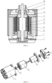
- the reference numerals in the Drawings are as follows: 1 - a motor housing; 2 - a bearing; 3 - a rotor; 4 - a stator; 5 - an upper pressing cover; 6 - a screw; 7 - a heat dissipation fan; 8 - an inner permanent magnet; 9 - a clamp sleeve; 10 - a core shaft; 11 - a rotor housing; 12 - an outer permanent magnet; 13 - a coil; 14 - a thermosetting material.
- FIGs. 1 and 2 A whole structure of a motor is shown in FIGs. 1 and 2 , a bearing 2 is pressed and fitted on each of two ends of a mandrel 10 in a rotor 3, the rotor 3 with the bearings pressed and fitted on its both ends is installed on a motor housing 1 along a direction shown in FIG 2 , and then a stator 4 is placed in a U-shaped annular groove of the rotor 3, an upper pressing cover 5 is placed above the stator 4 along the direction shown in FIG. 2 , and finally the upper pressing cover 5 and the stator 4 are fixed on the motor housing 1 by screws 6.
- the rotor 3 is formed by attaching permanent magnets on two sides of a U-shaped inner chamber formed by a core shaft 10, a heat dissipation fan 7 and a rotor housing 11.
- a structure of an inner layer of the rotor is shown in FIG. 4 , inner permanent magnets 8 are attached on the core shaft 10 in a manner that N, S poles are alternately arranged, the heat dissipation fan 7 and a clamp sleeve 9 are pressed and fitted on two ends of the core shaft 10 respectively to snap annular protrusions of the heat dissipation fan 7 and the clamp sleeve 9 into the grooves of the inner permanent magnets 8 for locking the inner permanent magnets 8 on the core shaft 10 together.
- the outer permanent magnets 12 are evenly adhered to an inner surface of the rotor housing 11 with an adhesive in a manner that N, S poles are alternately arranged, to form an outer portion of the rotor, and the outer portion of the rotor is pressed and fitted to the heat dissipation fan 7 to form an integral rotor 3.
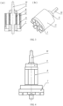
- FIG. 5 which illustrates a structure of the stator 4
- peripheral portion thereof is made of a special thermosetting material 14 by pouring, heating and press forming
- an inner coil 13 thereof is formed by winding enameled wires at its outer side by using forming process equipment.
- the enameled wire is wound around the forming process equipment by means of combining multiple enameled wires into a phase line; successively superposing three phase lines, i.e., a U-phase line, a V-phase line and a W-phase line; and winding each phase line in a toothed circle shape.
- the column type coreless motor described in the disclosure is powered by a lithium battery or a constant voltage direct current power supply, current is regulated by a controller and passes through an annular-shaped closed coil 13 with constant magnetic flux to drive a rotor 3 to rotate, and an intermediate core shaft 10 outputs the power to the used equipment.
Landscapes
- Engineering & Computer Science (AREA)
- Power Engineering (AREA)
- Motor Or Generator Cooling System (AREA)
- Windings For Motors And Generators (AREA)
Claims (4)
- Moteur de type colonne sans partie centrale, comprenant un corps qui inclut un boîtier de moteur (1), un rotor (3) et un stator (4), le moteur est configuré pour que : le rotor (3) soit supporté par des paliers (2) dans le boîtier de moteur (1) et un couvercle-pression supérieur (5), le stator (4) soit placé dans une rainure annulaire en forme de U du rotor (3) et positionnée par le couvercle-pression supérieur (5) et le boîtier de moteur (1),dans lequel le rotor (3) est une structure de type colonne avec la rainure annulaire en forme de U définie par un arbre central (10), un ventilateur de dissipation de chaleur (7) et un boîtier de rotor (11) ; une face d'extrémité du rotor (3) est pourvue du ventilateur de dissipation de chaleur (7) qui est encastré sur le boîtier de rotor (11) ; un côté intérieur du boîtier de moteur (1) est pourvu d'un passage d'air de dissipation de chaleur incluant des aubes de guidage,dans lequel le rotor (3) inclut l'arbre central (10), le ventilateur de dissipation de chaleur (7), un manchon de serrage (9) et des aimants permanents intérieurs (8) et des aimants permanents extérieurs (12), dans lequel les aimants permanents intérieurs (8) sont attachés à une périphérie extérieure de l'arbre central (10), et les aimants permanents extérieurs (12) sont fixés sur une surface latérale intérieure du boîtier de rotor (11),dans lequel les aimants permanents intérieurs (8) sont attachés sur l'arbre central (10) de manière telle que des pôles N et S des aimants permanents intérieurs (8) soient agencés de façon alternée, et les aimants permanents intérieurs (8) sont verrouillés sur l'arbre central (10) en pressant et ajustant le ventilateur de dissipation de chaleur (7) et le manchon de serrage (9) sur deux extrémités de l'arbre central (10) respectivement pour encliqueter des saillies annulaires du ventilateur de dissipation de chaleur (7) et du manchon de serrage (9) dans des rainures des aimants permanents intérieurs (8), etdans lequel les aimants permanents extérieurs (12) sont collés uniformément à la surface latérale intérieure du boîtier de rotor (11) avec un adhésif de manière telle que des pôles N, S des aimants permanents extérieurs soient agencés de façon alternée, pour former une portion extérieure du rotor (3), et la portion extérieure du rotor est pressée et ajustée sur le ventilateur de dissipation de chaleur (7) pour former un rotor monobloc.
- Moteur de type colonne sans partie centrale selon la revendication 1, dans lequel le ventilateur de dissipation de chaleur (7) et le passage d'air de dissipation de chaleur sur le boîtier de moteur (1) constituent un système de dissipation de chaleur, et
de la chaleur générée par une bobine (13) du stator est soufflée par le ventilateur de dissipation de chaleur (7) jusqu'aux aubes de guidage sur le boîtier de moteur (1) et s'écoule à travers le passage d'air de dissipation de chaleur hors d'une extrémité du passage d'air, pour jouer un rôle de dissipation de chaleur directionnelle. - Moteur de type colonne sans partie centrale selon une quelconque revendication précédente, dans lequel le stator (4) est fait en solidifiant une bobine (13) dans celui-ci avec un matériau thermodurcissable (14) par l'intermédiaire d'un dispositif de pression, la bobine est enroulée en combinant de multiples fils émaillés en une ligne de phase ; en superposant successivement des lignes triphasées, à savoir, une ligne de phase U, une ligne de phase V et une ligne de phase W ; et enroulant chaque ligne de phase en une forme de cercle denté.
- Moteur de type colonne sans partie centrale selon une quelconque revendication précédente, dans lequel le stator (4) est fixé par une vis (6) après être positionné par le couvercle-pression supérieur (5) et le boîtier de moteur (1).
Applications Claiming Priority (1)
| Application Number | Priority Date | Filing Date | Title |
|---|---|---|---|
| CN201911026468.7A CN110649731A (zh) | 2019-10-26 | 2019-10-26 | 柱式无铁芯电机 |
Publications (3)
| Publication Number | Publication Date |
|---|---|
| EP3813232A1 EP3813232A1 (fr) | 2021-04-28 |
| EP3813232B1 true EP3813232B1 (fr) | 2024-08-14 |
| EP3813232C0 EP3813232C0 (fr) | 2024-08-14 |
Family
ID=69013588
Family Applications (1)
| Application Number | Title | Priority Date | Filing Date |
|---|---|---|---|
| EP20193042.7A Active EP3813232B1 (fr) | 2019-10-26 | 2020-08-27 | Moteur dépourvu de partie centrale de type colonne |
Country Status (3)
| Country | Link |
|---|---|
| US (1) | US11509195B2 (fr) |
| EP (1) | EP3813232B1 (fr) |
| CN (1) | CN110649731A (fr) |
Families Citing this family (3)
| Publication number | Priority date | Publication date | Assignee | Title |
|---|---|---|---|---|
| US20240022126A1 (en) * | 2021-06-07 | 2024-01-18 | Black & Decker Inc. | Rotor magnet retention structure in brushless motor |
| CN113395120A (zh) * | 2021-06-09 | 2021-09-14 | 复汉海志(江苏)科技有限公司 | 一种lora自组无线网信号检测装置及其检测方法 |
| CN120915049A (zh) * | 2025-10-13 | 2025-11-07 | 洛阳精耕拓科技有限公司 | 一种高稳定性永磁体磁力电动机 |
Family Cites Families (14)
| Publication number | Priority date | Publication date | Assignee | Title |
|---|---|---|---|---|
| JPS61258643A (ja) * | 1985-05-10 | 1986-11-17 | Hitachi Ltd | 外側回転子直流ブラシレスモ−トル |
| DE4107602A1 (de) * | 1991-03-09 | 1992-09-10 | Bosch Gmbh Robert | Permanentmagnetrotor fuer elektrische maschinen |
| DE4342780A1 (de) * | 1993-12-15 | 1995-06-22 | Siemens Ag | Antriebseinheit |
| US6873085B2 (en) * | 2001-05-16 | 2005-03-29 | G & G Technology, Inc. | Brushless motor |
| KR100529888B1 (ko) * | 2003-02-20 | 2005-11-22 | 엘지전자 주식회사 | 모터 및 그 모터가 설치된 세탁기 |
| CN2764046Y (zh) * | 2004-11-02 | 2006-03-08 | 王和平 | 一种高压高功率密度无铁芯电机 |
| JP2009278751A (ja) * | 2008-05-14 | 2009-11-26 | Kokusan Denki Co Ltd | スタータジェネレータ |
| CN202004614U (zh) * | 2011-01-25 | 2011-10-05 | 深圳市仓兴达科技有限公司 | 具有内外转子的无铁芯无刷永磁直流电机 |
| US9246365B2 (en) * | 2012-01-23 | 2016-01-26 | Aisan Kogyo Kabushiki Kaisha | Regulation of permanent magnet motion in a brushless motor |
| WO2015092884A1 (fr) * | 2013-12-18 | 2015-06-25 | 株式会社安川電機 | Machine électrique tournante |
| WO2016035358A1 (fr) * | 2014-09-04 | 2016-03-10 | 株式会社エムリンク | Machine électrique tournante sans noyau à stator comprenant une bobine cylindrique et procédé de refroidissement associé |
| WO2018078779A1 (fr) * | 2016-10-27 | 2018-05-03 | 三菱電機株式会社 | Rouleau |
| CN107134889A (zh) * | 2017-06-01 | 2017-09-05 | 姜春辉 | 一种筒式外转子无铁芯电机 |
| CN210744861U (zh) * | 2019-10-26 | 2020-06-12 | 山东华盛农业药械有限责任公司 | 一种柱式无铁芯电机 |
-
2019
- 2019-10-26 CN CN201911026468.7A patent/CN110649731A/zh active Pending
-
2020
- 2020-08-25 US US17/002,593 patent/US11509195B2/en active Active
- 2020-08-27 EP EP20193042.7A patent/EP3813232B1/fr active Active
Also Published As
| Publication number | Publication date |
|---|---|
| US11509195B2 (en) | 2022-11-22 |
| CN110649731A (zh) | 2020-01-03 |
| EP3813232A1 (fr) | 2021-04-28 |
| EP3813232C0 (fr) | 2024-08-14 |
| US20210126510A1 (en) | 2021-04-29 |
Similar Documents
| Publication | Publication Date | Title |
|---|---|---|
| EP3813232B1 (fr) | Moteur dépourvu de partie centrale de type colonne | |
| US8310126B1 (en) | Radial flux permanent magnet AC motor/generator | |
| US8294309B2 (en) | Electrical rotating machine | |
| US20100264769A1 (en) | Induction motor having rotors arranged concentrically and being able to used to generator | |
| US7195107B2 (en) | Machine having pulley coupled to rotor and partially overlying stator, elevator system including machine, and drive method | |
| WO2009055956A1 (fr) | Moteur à courant continu à aimant permanent sans balai triphasé à onde carrée | |
| KR102527294B1 (ko) | 축방향 자속 회전기기 | |
| CN112491198A (zh) | 一种混合集成离心风机和轴流风机的自扇冷轴向磁通电机 | |
| CN208299655U (zh) | 双气隙电动机 | |
| CN203193469U (zh) | 无铁芯盘式直流无刷电机 | |
| CN101395786A (zh) | 电机转子 | |
| EP2013960B1 (fr) | Moteur electrique avec un faible nombre de revolutions, en particulier pour entrainer des dispositifs de levage | |
| CN210724516U (zh) | 一种双定子单转子盘式永磁电动机 | |
| CN210744861U (zh) | 一种柱式无铁芯电机 | |
| CN112383192B (zh) | 一种带内置轴流风机的自扇冷轴向磁通电机 | |
| CN210898682U (zh) | 一种节能电机转子 | |
| CN207732599U (zh) | 基于脉动磁场的异步电动机 | |
| CN210536361U (zh) | 一种定子连接结构 | |
| CN201038968Y (zh) | 盘式转子电机 | |
| KR20110086786A (ko) | 다극 바이패스 디스크 모터. | |
| CN223666146U (zh) | 快速散热外转子电机 | |
| WO2004112222A1 (fr) | Machine electrique equipee d'un systeme de refroidissement | |
| CN208835966U (zh) | 电机 | |
| CN2311093Y (zh) | 一种感应式马达之定子 | |
| KR20150049518A (ko) | 에이에프피엠 발전기 |
Legal Events
| Date | Code | Title | Description |
|---|---|---|---|
| PUAI | Public reference made under article 153(3) epc to a published international application that has entered the european phase |
Free format text: ORIGINAL CODE: 0009012 |
|
| STAA | Information on the status of an ep patent application or granted ep patent |
Free format text: STATUS: REQUEST FOR EXAMINATION WAS MADE |
|
| 17P | Request for examination filed |
Effective date: 20201222 |
|
| AK | Designated contracting states |
Kind code of ref document: A1 Designated state(s): AL AT BE BG CH CY CZ DE DK EE ES FI FR GB GR HR HU IE IS IT LI LT LU LV MC MK MT NL NO PL PT RO RS SE SI SK SM TR |
|
| AX | Request for extension of the european patent |
Extension state: BA ME |
|
| STAA | Information on the status of an ep patent application or granted ep patent |
Free format text: STATUS: EXAMINATION IS IN PROGRESS |
|
| 17Q | First examination report despatched |
Effective date: 20221118 |
|
| RAP1 | Party data changed (applicant data changed or rights of an application transferred) |
Owner name: SHANDONG HUASHENG PESTICIDE MACHINERY CO., LTD |
|
| GRAP | Despatch of communication of intention to grant a patent |
Free format text: ORIGINAL CODE: EPIDOSNIGR1 |
|
| STAA | Information on the status of an ep patent application or granted ep patent |
Free format text: STATUS: GRANT OF PATENT IS INTENDED |
|
| INTG | Intention to grant announced |
Effective date: 20240318 |
|
| GRAS | Grant fee paid |
Free format text: ORIGINAL CODE: EPIDOSNIGR3 |
|
| GRAA | (expected) grant |
Free format text: ORIGINAL CODE: 0009210 |
|
| STAA | Information on the status of an ep patent application or granted ep patent |
Free format text: STATUS: THE PATENT HAS BEEN GRANTED |
|
| AK | Designated contracting states |
Kind code of ref document: B1 Designated state(s): AL AT BE BG CH CY CZ DE DK EE ES FI FR GB GR HR HU IE IS IT LI LT LU LV MC MK MT NL NO PL PT RO RS SE SI SK SM TR |
|
| REG | Reference to a national code |
Ref country code: GB Ref legal event code: FG4D |
|
| REG | Reference to a national code |
Ref country code: CH Ref legal event code: EP |
|
| REG | Reference to a national code |
Ref country code: DE Ref legal event code: R096 Ref document number: 602020035644 Country of ref document: DE |
|
| REG | Reference to a national code |
Ref country code: IE Ref legal event code: FG4D |
|
| U01 | Request for unitary effect filed |
Effective date: 20240820 |
|
| U07 | Unitary effect registered |
Designated state(s): AT BE BG DE DK EE FI FR IT LT LU LV MT NL PT RO SE SI Effective date: 20240902 |
|
| U20 | Renewal fee for the european patent with unitary effect paid |
Year of fee payment: 5 Effective date: 20240920 |
|
| PG25 | Lapsed in a contracting state [announced via postgrant information from national office to epo] |
Ref country code: NO Free format text: LAPSE BECAUSE OF FAILURE TO SUBMIT A TRANSLATION OF THE DESCRIPTION OR TO PAY THE FEE WITHIN THE PRESCRIBED TIME-LIMIT Effective date: 20241114 |
|
| PG25 | Lapsed in a contracting state [announced via postgrant information from national office to epo] |
Ref country code: GR Free format text: LAPSE BECAUSE OF FAILURE TO SUBMIT A TRANSLATION OF THE DESCRIPTION OR TO PAY THE FEE WITHIN THE PRESCRIBED TIME-LIMIT Effective date: 20241115 Ref country code: PL Free format text: LAPSE BECAUSE OF FAILURE TO SUBMIT A TRANSLATION OF THE DESCRIPTION OR TO PAY THE FEE WITHIN THE PRESCRIBED TIME-LIMIT Effective date: 20240814 |
|
| PG25 | Lapsed in a contracting state [announced via postgrant information from national office to epo] |
Ref country code: IS Free format text: LAPSE BECAUSE OF FAILURE TO SUBMIT A TRANSLATION OF THE DESCRIPTION OR TO PAY THE FEE WITHIN THE PRESCRIBED TIME-LIMIT Effective date: 20241214 |
|
| PG25 | Lapsed in a contracting state [announced via postgrant information from national office to epo] |
Ref country code: HR Free format text: LAPSE BECAUSE OF FAILURE TO SUBMIT A TRANSLATION OF THE DESCRIPTION OR TO PAY THE FEE WITHIN THE PRESCRIBED TIME-LIMIT Effective date: 20240814 |
|
| PG25 | Lapsed in a contracting state [announced via postgrant information from national office to epo] |
Ref country code: RS Free format text: LAPSE BECAUSE OF FAILURE TO SUBMIT A TRANSLATION OF THE DESCRIPTION OR TO PAY THE FEE WITHIN THE PRESCRIBED TIME-LIMIT Effective date: 20241114 Ref country code: ES Free format text: LAPSE BECAUSE OF FAILURE TO SUBMIT A TRANSLATION OF THE DESCRIPTION OR TO PAY THE FEE WITHIN THE PRESCRIBED TIME-LIMIT Effective date: 20240814 |
|
| PG25 | Lapsed in a contracting state [announced via postgrant information from national office to epo] |
Ref country code: RS Free format text: LAPSE BECAUSE OF FAILURE TO SUBMIT A TRANSLATION OF THE DESCRIPTION OR TO PAY THE FEE WITHIN THE PRESCRIBED TIME-LIMIT Effective date: 20241114 Ref country code: PL Free format text: LAPSE BECAUSE OF FAILURE TO SUBMIT A TRANSLATION OF THE DESCRIPTION OR TO PAY THE FEE WITHIN THE PRESCRIBED TIME-LIMIT Effective date: 20240814 Ref country code: NO Free format text: LAPSE BECAUSE OF FAILURE TO SUBMIT A TRANSLATION OF THE DESCRIPTION OR TO PAY THE FEE WITHIN THE PRESCRIBED TIME-LIMIT Effective date: 20241114 Ref country code: IS Free format text: LAPSE BECAUSE OF FAILURE TO SUBMIT A TRANSLATION OF THE DESCRIPTION OR TO PAY THE FEE WITHIN THE PRESCRIBED TIME-LIMIT Effective date: 20241214 Ref country code: HR Free format text: LAPSE BECAUSE OF FAILURE TO SUBMIT A TRANSLATION OF THE DESCRIPTION OR TO PAY THE FEE WITHIN THE PRESCRIBED TIME-LIMIT Effective date: 20240814 Ref country code: GR Free format text: LAPSE BECAUSE OF FAILURE TO SUBMIT A TRANSLATION OF THE DESCRIPTION OR TO PAY THE FEE WITHIN THE PRESCRIBED TIME-LIMIT Effective date: 20241115 Ref country code: ES Free format text: LAPSE BECAUSE OF FAILURE TO SUBMIT A TRANSLATION OF THE DESCRIPTION OR TO PAY THE FEE WITHIN THE PRESCRIBED TIME-LIMIT Effective date: 20240814 |
|
| REG | Reference to a national code |
Ref country code: CH Ref legal event code: PL |
|
| PG25 | Lapsed in a contracting state [announced via postgrant information from national office to epo] |
Ref country code: SM Free format text: LAPSE BECAUSE OF FAILURE TO SUBMIT A TRANSLATION OF THE DESCRIPTION OR TO PAY THE FEE WITHIN THE PRESCRIBED TIME-LIMIT Effective date: 20240814 |
|
| PG25 | Lapsed in a contracting state [announced via postgrant information from national office to epo] |
Ref country code: CH Free format text: LAPSE BECAUSE OF NON-PAYMENT OF DUE FEES Effective date: 20240831 |
|
| PG25 | Lapsed in a contracting state [announced via postgrant information from national office to epo] |
Ref country code: CZ Free format text: LAPSE BECAUSE OF FAILURE TO SUBMIT A TRANSLATION OF THE DESCRIPTION OR TO PAY THE FEE WITHIN THE PRESCRIBED TIME-LIMIT Effective date: 20240814 |
|
| PG25 | Lapsed in a contracting state [announced via postgrant information from national office to epo] |
Ref country code: SK Free format text: LAPSE BECAUSE OF FAILURE TO SUBMIT A TRANSLATION OF THE DESCRIPTION OR TO PAY THE FEE WITHIN THE PRESCRIBED TIME-LIMIT Effective date: 20240814 |
|
| PLBE | No opposition filed within time limit |
Free format text: ORIGINAL CODE: 0009261 |
|
| STAA | Information on the status of an ep patent application or granted ep patent |
Free format text: STATUS: NO OPPOSITION FILED WITHIN TIME LIMIT |
|
| PG25 | Lapsed in a contracting state [announced via postgrant information from national office to epo] |
Ref country code: MC Free format text: LAPSE BECAUSE OF FAILURE TO SUBMIT A TRANSLATION OF THE DESCRIPTION OR TO PAY THE FEE WITHIN THE PRESCRIBED TIME-LIMIT Effective date: 20240814 |
|
| 26N | No opposition filed |
Effective date: 20250515 |
|
| GBPC | Gb: european patent ceased through non-payment of renewal fee |
Effective date: 20241114 |
|
| PG25 | Lapsed in a contracting state [announced via postgrant information from national office to epo] |
Ref country code: IE Free format text: LAPSE BECAUSE OF NON-PAYMENT OF DUE FEES Effective date: 20240827 |
|
| U20 | Renewal fee for the european patent with unitary effect paid |
Year of fee payment: 6 Effective date: 20250709 |
|
| PG25 | Lapsed in a contracting state [announced via postgrant information from national office to epo] |
Ref country code: GB Free format text: LAPSE BECAUSE OF NON-PAYMENT OF DUE FEES Effective date: 20241114 |