EP3812673B1 - Kühlschrank - Google Patents
Kühlschrank Download PDFInfo
- Publication number
- EP3812673B1 EP3812673B1 EP20206714.6A EP20206714A EP3812673B1 EP 3812673 B1 EP3812673 B1 EP 3812673B1 EP 20206714 A EP20206714 A EP 20206714A EP 3812673 B1 EP3812673 B1 EP 3812673B1
- Authority
- EP
- European Patent Office
- Prior art keywords
- refrigerator
- shelf
- guide
- cabinet
- connecting bar
- Prior art date
- Legal status (The legal status is an assumption and is not a legal conclusion. Google has not performed a legal analysis and makes no representation as to the accuracy of the status listed.)
- Active
Links
Images


Classifications
-
- F—MECHANICAL ENGINEERING; LIGHTING; HEATING; WEAPONS; BLASTING
- F25—REFRIGERATION OR COOLING; COMBINED HEATING AND REFRIGERATION SYSTEMS; HEAT PUMP SYSTEMS; MANUFACTURE OR STORAGE OF ICE; LIQUEFACTION SOLIDIFICATION OF GASES
- F25D—REFRIGERATORS; COLD ROOMS; ICE-BOXES; COOLING OR FREEZING APPARATUS NOT OTHERWISE PROVIDED FOR
- F25D23/00—General constructional features
- F25D23/02—Doors; Covers
- F25D23/028—Details
-
- A—HUMAN NECESSITIES
- A47—FURNITURE; DOMESTIC ARTICLES OR APPLIANCES; COFFEE MILLS; SPICE MILLS; SUCTION CLEANERS IN GENERAL
- A47B—TABLES; DESKS; OFFICE FURNITURE; CABINETS; DRAWERS; GENERAL DETAILS OF FURNITURE
- A47B96/00—Details of cabinets, racks or shelf units not covered by a single one of groups A47B43/00 - A47B95/00; General details of furniture
- A47B96/02—Shelves
- A47B96/025—Shelves with moving elements, e.g. movable extensions or link elements
-
- F—MECHANICAL ENGINEERING; LIGHTING; HEATING; WEAPONS; BLASTING
- F25—REFRIGERATION OR COOLING; COMBINED HEATING AND REFRIGERATION SYSTEMS; HEAT PUMP SYSTEMS; MANUFACTURE OR STORAGE OF ICE; LIQUEFACTION SOLIDIFICATION OF GASES
- F25D—REFRIGERATORS; COLD ROOMS; ICE-BOXES; COOLING OR FREEZING APPARATUS NOT OTHERWISE PROVIDED FOR
- F25D23/00—General constructional features
- F25D23/02—Doors; Covers
-
- F—MECHANICAL ENGINEERING; LIGHTING; HEATING; WEAPONS; BLASTING
- F25—REFRIGERATION OR COOLING; COMBINED HEATING AND REFRIGERATION SYSTEMS; HEAT PUMP SYSTEMS; MANUFACTURE OR STORAGE OF ICE; LIQUEFACTION SOLIDIFICATION OF GASES
- F25D—REFRIGERATORS; COLD ROOMS; ICE-BOXES; COOLING OR FREEZING APPARATUS NOT OTHERWISE PROVIDED FOR
- F25D23/00—General constructional features
- F25D23/06—Walls
- F25D23/062—Walls defining a cabinet
-
- F—MECHANICAL ENGINEERING; LIGHTING; HEATING; WEAPONS; BLASTING
- F25—REFRIGERATION OR COOLING; COMBINED HEATING AND REFRIGERATION SYSTEMS; HEAT PUMP SYSTEMS; MANUFACTURE OR STORAGE OF ICE; LIQUEFACTION SOLIDIFICATION OF GASES
- F25D—REFRIGERATORS; COLD ROOMS; ICE-BOXES; COOLING OR FREEZING APPARATUS NOT OTHERWISE PROVIDED FOR
- F25D23/00—General constructional features
- F25D23/06—Walls
- F25D23/065—Details
- F25D23/067—Supporting elements
-
- F—MECHANICAL ENGINEERING; LIGHTING; HEATING; WEAPONS; BLASTING
- F25—REFRIGERATION OR COOLING; COMBINED HEATING AND REFRIGERATION SYSTEMS; HEAT PUMP SYSTEMS; MANUFACTURE OR STORAGE OF ICE; LIQUEFACTION SOLIDIFICATION OF GASES
- F25D—REFRIGERATORS; COLD ROOMS; ICE-BOXES; COOLING OR FREEZING APPARATUS NOT OTHERWISE PROVIDED FOR
- F25D23/00—General constructional features
- F25D23/06—Walls
- F25D23/069—Cooling space dividing partitions
-
- F—MECHANICAL ENGINEERING; LIGHTING; HEATING; WEAPONS; BLASTING
- F25—REFRIGERATION OR COOLING; COMBINED HEATING AND REFRIGERATION SYSTEMS; HEAT PUMP SYSTEMS; MANUFACTURE OR STORAGE OF ICE; LIQUEFACTION SOLIDIFICATION OF GASES
- F25D—REFRIGERATORS; COLD ROOMS; ICE-BOXES; COOLING OR FREEZING APPARATUS NOT OTHERWISE PROVIDED FOR
- F25D25/00—Charging, supporting, and discharging the articles to be cooled
- F25D25/02—Charging, supporting, and discharging the articles to be cooled by shelves
- F25D25/024—Slidable shelves
-
- A—HUMAN NECESSITIES
- A47—FURNITURE; DOMESTIC ARTICLES OR APPLIANCES; COFFEE MILLS; SPICE MILLS; SUCTION CLEANERS IN GENERAL
- A47B—TABLES; DESKS; OFFICE FURNITURE; CABINETS; DRAWERS; GENERAL DETAILS OF FURNITURE
- A47B2210/00—General construction of drawers, guides and guide devices
- A47B2210/17—Drawers used in connection with household appliances
- A47B2210/175—Refrigerators or freezers
-
- F—MECHANICAL ENGINEERING; LIGHTING; HEATING; WEAPONS; BLASTING
- F25—REFRIGERATION OR COOLING; COMBINED HEATING AND REFRIGERATION SYSTEMS; HEAT PUMP SYSTEMS; MANUFACTURE OR STORAGE OF ICE; LIQUEFACTION SOLIDIFICATION OF GASES
- F25D—REFRIGERATORS; COLD ROOMS; ICE-BOXES; COOLING OR FREEZING APPARATUS NOT OTHERWISE PROVIDED FOR
- F25D2201/00—Insulation
- F25D2201/10—Insulation with respect to heat
Definitions
- the present disclosure relates to a refrigerator.
- a refrigerator is a household appliance used to store food in a refrigerated or frozen state.
- a home bar, ice maker, shelf or door box has been mounted on the back face of the refrigerator door.
- a refrigerator is a household appliance used for storing food in a refrigerated or frozen state.
- a shelf or storage box mounted on a storage compartment of the refrigerator main body may interfere with components mounted on the back face of the refrigerator door.
- a front end of the shelf or storage box mounted inside the storage room of the refrigerator main body that is, a refrigerator compartment or a freezer compartment
- a front end of the shelf or storage box mounted inside the storage room of the refrigerator main body that is, a refrigerator compartment or a freezer compartment
- the user may have inconvenience to insert his/her hand deeply into the storage room.
- This problem is more pronounced in large refrigerators. That is, in the casing of the large refrigerator, an anteroposterior dimension of a refrigerator compartment or a freezer compartment is large. Thus, this has the disadvantage that the user cannot easily pull out the food stored deeply in the rear-end portion of the shelf.
- Korean Patent Publication No. 2010-0130357 discloses a refrigerator in which a shelf or a storage box installed in a refrigerator compartment or a freezer compartment is placed on an L-shaped storage frame, and the storage frame is connected to a bottom of the refrigerator door via a multi-joint link.
- the shelf and the storage box are always drawn out in a front direction of the refrigerator in conjunction with the opening of the refrigerator door.
- the shelf and storage box cannot be used in a fixed position.
- the frame structure for drawing out the shelf is exposed to the outside.
- the inside of the refrigerator cannot be visible clearly, and it is difficult to clean the inside of the refrigerator.
- the present disclosure is proposed to improve the problems of the prior art as presented in the above.
- the purpose of the present disclosure is to provide a refrigerator in which coupling between a shelf and a withdrawing mechanism for withdrawing the shelf may be released by a simple operation.
- Figures 1-9 and 13-17 show embodiments being useful for understanding the invention, which are outside the subject-matter of the claims.
- Figures 10-12 show an embodiment according to the present invention, which discloses a refrigerator according to claim 1.
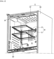
- FIG. 1 is a perspective view of a refrigerator according to an embodiment of the present disclosure.
- FIG. 2 is a perspective view of a refrigerator according to an embodiment of the present disclosure.
- the refrigerator 10 may include a cabinet 11 having a storage space formed therein, and a door that is pivotally or slidably mounted on the front face of the cabinet 11 to selectively open and close the storage space.
- the storage space may include a refrigerator compartment 111 provided to store food in a refrigerated state, and a freezer compartment 112 provided to store the food in a frozen state.
- the refrigerator compartment 111 may be disposed above, below or to the side of the freezer compartment 112.
- the refrigerator compartment 111 is partitioned from the freezer compartment 112 by a mullion 113.
- a bottom freezer type refrigerator in which the refrigerator compartment 111 is disposed above the freezer compartment 112 will be exemplified.
- the door includes a refrigerator compartment door 12 for opening and closing the refrigerator compartment 111 and a freezer compartment door 13 for opening and closing the freezer compartment 112.
- the refrigerator compartment door 12 may include a single pivotable door pivotally provided on the side edge of the front face of the cabinet 11, or French doors which are pivotally provided on the left and right edges of the front face of the cabinet 11 respectively and which open or close an opening in the front face of the refrigerator compartment 111.
- the former and latter door may be selected depending on the structure.
- the refrigerator compartment door 12 is provided in the form of the French doors will be illustrated.
- the freezer compartment door 13 may also be provided as a French type door as in the refrigerator compartment door 12, or alternatively as a drawer type door.
- the pair of refrigerator compartment doors 12 are pivotally connected to the front face of the cabinet 11 via a hinge assembly.
- a plurality of storage casings 121 including a shelf or a basket may be arranged on the back face of the pair of the refrigerator compartment doors 12 in the vertical direction.
- a plurality of storage boxes 115 and a plurality of shelf assemblies 20 may be arranged inside the refrigerator compartment 111.
- the plurality of storage boxes 115 may be arranged side by side on the left and right sides of the refrigerator compartment 111.
- the plurality of storage boxes 115 may be arranged in the vertical direction as well.
- the plurality of shelf assemblies 20 may be disposed side by side on the left and right sides of the refrigerator compartment 111. Further, the plurality of shelf assemblies 20 may be arranged in the vertical direction as well.
- the cabinet 11 may include an inner cabinet 117 defining the refrigerator compartment 111 and the freezer compartment 112, an outer cabinet 116 surrounding the inner cabinet 117 and forming the appearance of the cabinet 11, and a thermal insulating material (not shown) filled between the inner cabinet 117 and the outer cabinet 116.
- the shelf assembly 20 may include a shelf support arm 21 in the form of a cantilever secured to the rear face of the inner cabinet 117, and a shelf 22 that slides in an anteroposterior direction along the shelf support arm 21 in a state of being seated on the top face of the shelf support arm 21.
- the user may open the refrigerator compartment door 12 on the left side to withdraw food stored in the storage box 115 and the shelf assembly 20 on the left side.
- the user may open the refrigerator compartment door 12 on the right side to withdraw food stored in the storage box 115 and the shelf assembly 20 on the right side.
- the refrigerator according to the embodiment of the present disclosure may include a shelf withdrawing mechanism 30 that allows the shelf assembly 20 located on the back face of the refrigerator compartment door to move forward of the refrigerator compartment 111 when either the left or right refrigerator compartment door is opened.
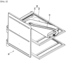
- FIG. 3 is a perspective view of the shelf withdrawing mechanism according to an embodiment of the present disclosure.
- FIG. 4 is an exploded perspective view of the withdrawing mechanism.
- the withdrawing mechanism 30 may allow the shelf 22 of the shelf assembly 20 to be withdrawn forward when the door 12 is opened. When the door 12 is closed, the withdrawing mechanism 30 functions to insert the shelf 22 into the refrigerator.
- the shelf assembly 20 is secured to a pair of support frames (not shown) mounted perpendicularly to the rear face of the refrigerator compartment 111.
- a catch hook protrudes from each of the left and right rear-end portion portions of the shelf support arm 21. Each catch hook is inserted into each of catch holes formed in the pair of support frames.
- the shelf 22 is coupled to the shelf support arm 21 to be slidable from the shelf support arm 21 in the anteroposterior direction.
- the withdrawing mechanism 30 may include an inner casing 34 that forms a portion of the side face of the refrigerator compartment 111, i.e., a portion of the inner cabinet 117, an outer casing 32 coupled with the inner casing 34 on the opposite side of the inner casing 34, a sliding member 33 provided between the inner casing 34 and the outer casing 32 and movable in the anteroposterior direction of the refrigerator 10, a link member 31 connecting the top face of the sliding member 33 to the top face of the door 12, and a connector 35 that connects the sliding member 33 to the shelf 22.
- the connector 35 may be removably coupled to the side face of the shelf 22 and may selectively be coupled to the sliding member 33.
- the link member 31 when opening the door 12, the link member 31 is moved forward while rotating about the center of rotation of the door 12. As a result, the sliding member 33 connected to the rear end of the link member 31 moves forward of the refrigerator 10. Moreover, as the sliding member 33 moves forward, the shelf 22 connected to the sliding member 33 via the connector 25 is moved forward.
- the outer casing 32 and the sliding member 33 may be placed in the space between the inner cabinet 117 and the outer cabinet 116. They may be surrounded by the heat insulating material to prevent shaking thereof. In addition, since the sliding member 33 is located outside the inner casing 34, the sliding member 33 is not exposed to the outside when the user opens the door 12 so that the refrigerator compartment 111 opens.
- FIG. 5 is a perspective view of the outer casing constituting the withdrawing mechanism according to the embodiment of the present disclosure.
- the outer casing 32 constituting the withdrawing mechanism 30 has a rectangular plate shape having a predetermined width W. Four edges of the outer casing are vertically bent to define the thickness. In addition, a plurality of coupling portions 323 may be formed on the bent portion of the outer casing 32.
- a plurality of coupling bosses 322 may protrude from the center of the inner face of the outer casing 32 and may be spaced apart from each other by a predetermined distance in the longitudinal direction of the outer casing 32.
- a plurality of guide grooves 321 are formed in the outer casing 32.
- Each groove 321 may extend by a predetermined length in the width direction of the outer casing 32.
- the plurality of guide grooves 321 may be arranged at regular intervals in the longitudinal direction of the outer casing 32.
- FIG. 6 is a perspective view of a sliding member constituting a withdrawing mechanism according to the embodiment of the present disclosure.
- the sliding member 33 constituting the withdrawing mechanism 30 may be formed in a substantially rectangular frame shape.
- the sliding member 33 may include an outer face 336 facing the outer casing 32, an inner face 335 ( FIG. 8 ) facing the inner casing 34 as the opposite face to the outer face 336, a front-end portion 331 facing the front face of the refrigerator 10, a rear-end portion 332 defining a face opposite the front-end portion 331, an upper-end portion 333 connecting the top faces of the front-end portion 331 and the rear-end portion 332, a lower-end portion 334 connecting the bottom face of the front-end portion 331 and the bottom face of the rear-end portion 332, a link-connection portion 337 vertically protruding from the upper-end portion 333, and a link-connection boss 338 protruding from the top face of the link-connection portion 337.
- a plurality of guide ribs 330b may be protruded from the outer face 336 of the sliding member 33 to guide movement of the sliding member 33 in the anteroposterior direction.
- a plurality of spacer ribs 330a may be protruded from the outer face 336 such that the outer casing 32 is spaced apart from the sliding member 33 by a predetermined distance.
- the guide rib 330b protrudes at a position corresponding to the guide groove 321 formed in the outer casing 32, is inserted into the guide groove 321, and moves in an anteroposterior direction.
- the guide groove 321 may be formed to protrude from the inner face of the outer casing 32 to the outer face thereof.
- the vertical width or thickness of the guide groove 321 may have a size corresponding to the thickness of the guide rib 330b. As moving the guide rib 330b along and in the guide groove 321, this may prevent the sliding member 33 from shaking when the member 33 is moving.
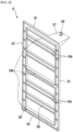
- FIG. 7 is a perspective view of the inner casing constituting the withdrawing mechanism according to the embodiment of the present disclosure.
- the inner casing 34 constituting the withdrawing mechanism 30 may include a casing body 345 having a rectangular plate shape corresponding to the shape of the outer casing 34, and a link cover portion 343 extending vertically from the top of the casing body 345.
- the inner casing 34 may further include an edge portion 346 bent outwardly from the edge of the casing body 345.
- a plurality of coupling holes 344 may be formed in the edge portion 346.
- the coupling portions 323 formed on the edge portions of the outer casing 32 are inserted into the coupling holes 344 respectively such that the inner casing 34 and the outer casing 32 may be integrally coupled to each other.
- a plurality of coupling holes 342 may be formed in the center of the casing body 345.
- the plurality of coupling holes 342 may be arranged at regular intervals in the longitudinal direction of the casing body 345.
- the coupling bosses 322 protruding from the outer casing 32 are respectively fitted into the plurality of coupling holes 342.
- a coupling member passing through the coupling hole 342 may be inserted into the coupling boss 322 such that the inner casing 34 and the outer casing 32 may be coupled together.
- the casing body 345 of the inner casing 34 and the outer casing 32 may be spaced apart from each other by the projecting length of the coupling boss 322 to define a space.
- the sliding member 33 may be received in the space.
- a number of guide slits 341 corresponding to the number of the shelves 22 are formed.
- the connector 35 may be inserted into the guide slit 341.
- the connector moves in and along the slit.
- the slit may be formed to position-correspond to the side face of the shelf assembly 20. Therefore, even when the shelf 22 moves in the anteroposterior direction, the guide slit 341 is not exposed to the outside due to the shelf support arm 21.
- the link cover portion 343 is constructed to have a space defined therein for accommodating the link member 31.
- the link cover portion 343 performs a shielding function for shielding the link member so that the link member 31 is not exposed to the interior of the refrigerator when the user opens the door 12.
- the link cover portion 343 has a horizontal portion extending horizontally from the top of the casing body 345 and a vertical portion extending upward from the edge of the horizontal portion.
- the vertical portion has a front wall 343a, a side wall 343b, and a rear wall 343c. The ends of the walls constituting the vertical portion are in close contact with the top face of the inner cabinet 117, that is, the ceiling of the refrigerator compartment 111.
- a link through-hole 343d through which the link member 31 passes may be formed in the front wall 343a. Therefore, a remaining portion of the link member 31 except for a portion of the member 31 protruding forward through the link through-hole 343d may be shielded by the link cover portion 343 and may not be exposed to the outside.
- the inner cabinet 117 may replace the casing body 345, and only the link cover portion 343 may be provided so as to connect the top and the ceiling portion of the inner cabinet 117.
- the guide slit 341 may be formed in the inner cabinet 117.
- the outer casing 32 may be coupled directly to the inner cabinet 117.
- FIG. 8 is a view showing a state where the connector constituting the withdrawing mechanism is connected to the sliding member according to an embodiment of the present disclosure.
- FIG. 9 is a perspective view of a state in which the connector is mounted on the shelf assembly.
- a receiving groove 339 is defined within the edge of the rear-end portion of the inner face 335 of the sliding member 33.
- a connector 35 that fits in the receiving groove 339 of the sliding member 33 is mounted on the shelf assembly 20.
- the connector 35 may be removably coupled to the edge of the bottom face of the shelf 22.
- the connector 35 may be connected to the shelf 22 and may be moved integrally with the shelf 22.
- a portion of the connector 35 may protrude outward from the rear end of the shelf support arm 21 and be exposed to the outside.
- substantially the protruding portion of the connector 35 is fitted into the receiving groove 339.
- the protruding portion of the connector 35 may be referred to as a "protrusion".
- the protrusion of the connector 35 may be inserted into the receiving groove 339 of the sliding member 33 through the guide slit 341 of the inner casing 34.
- the connector 35 may be connected to the sliding member 33 and may be moved integrally with the sliding member 33.
- the connector 35 and receiving groove 339 may be formed at a point corresponding to the position of the shelf assembly 20. Each of numbers of the connectors 35 and receiving grooves 339 may correspond to the number of the shelf assemblies 20.
- inserting the protrusion of the connector 35 by a predetermined length inwardly of the shelf assembly 20 may allow the protrusion to be separated from the receiving groove 339 of the sliding member 33.
- the protrusion since the length of the protrusion is relatively short, the protrusion does not reach the receiving groove 339 of the sliding member 33.
- the shelf 22 is not withdrawn forward in a response wot the opening operation of the door 12.
- the position of the shelf 22 may be maintained on the top face of the shelf support arm 21.
- the user inserts the protrusion of the connector 35 into the inside of the shelf 22 by the predetermined length via pressing of a pressing portion on the connector 35.
- the association movement between the door 12 and the shelf 22 may be disabled.
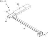
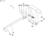
- FIG. 10 is a perspective view of the connector according to an embodiment of the present invention, which discloses a refrigerator according to claim 1.
- FIG. 11 is an exploded perspective view of the connector.
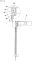
- FIG. 12 is a vertical cross-sectional view taken along a line A-A of FIG. 10 .
- the connector 35 according to an embodiment of the present invention, which discloses a refrigerator according to claim 1, includes a connecting unit 351 protruding out of the shelf assembly 20 for being selectively inserted in the receiving groove 339 of the sliding member 33, a guide unit 352 surrounding a part of the connecting unit 351 and guiding the connecting unit 351 so as to be movable in the lateral direction of the refrigerator 10, an actuating unit 353 for enabling inserting of the connecting unit 351 into the interior of the guide unit 352.
- the connecting unit 351 is a portion that protrudes toward the side of the shelf assembly 20 and is selectively inserted in the receiving groove 339.
- the connecting unit 351 is accommodated in a receiving space 3523 defined in the guide unit 352 and is configured to be movable in the lateral direction of the refrigerator 10.
- the connecting unit 351 may include a body portion 3511 received within the receiving space 3523 and having one end selectively inserted into the receiving groove 339, a coupling portion 3512 formed on the bottom face of the body portion 3511, a contact portion 3515 which is coupled to the coupling portion 3512 and has a first inclined face (3516 in FIG. 13 ) on one end thereof, an extending portion 3513 protruding from the side face of the body portion 3511, and an elastic member 3514 surrounding the extending portion 3513.
- the body portion 3511 has a rod shape extending long in the lateral direction of the refrigerator 10.
- the edge portion of the portion 3511 may be rounded.
- the body portion 3511 may, in part, be placed on the top face of the rear end of the he actuating unit 353 while the body portion 3511 may be partially received within the receiving space 3523 defined within the guide unit 352. In addition, the body portion 3511 may be moved laterally within the receiving space 3523.
- the extending portion 3513 may be a portion wound by the elastic member 3514 so that the body portion 3511 moves laterally within the receiving space 325.
- the extending portion 3513 may protrude a predetermined length from the side face of the body portion 3511.
- the extending portion 3513 may be received in the receiving space 3523 defined within the guide unit 352.
- the elastic member 3514 may be wound around the extending portion 3513 to elastically support the side surface of the body portion 3511.
- the elastic member 3514 may include a spring. One end of the elastic member 3514 contacts the side face of the body portion 3511, while the other end of the member 3514 may be fixed to the inner wall of the guide unit 352. Accordingly, when the body portion 3511 is moved to the right side of the refrigerator 10, the elastic member 3514 is compressed. At this time, the elastic member 3514 may provide a pressing force for pressing the body portion 3511 toward the left side of the refrigerator 10 using the restoring force thereof.
- the coupling portion 3512 may be a portion coupled to the contact portion 3515.
- the coupling portion 3512 may be connected to the contact portion 3515 and may be moved integrally with the coupling portion 3512.
- the contact portion 3515 may be coupled to the connecting unit 351 and inserted into the actuating unit 353.
- the contact portion 3515 may be coupled to the coupling portion 3512 and be accommodated in a predetermined space within the actuating unit 353.
- the first inclined face 3516 may be formed on one end of the contact portion 3515.
- the contact portion 3515 may be moved laterally within the predetermined space via relative movement with a second inclined face 3544 of the movable portion 354, which will be described later.
- the contact portion 3515 is illustrated as being separate from the body portion 3511. However, the present disclosure is not so limited.
- the contact portion 3515 may be integrally formed on the bottom face of the body portion 3511.
- the guide unit 352 serves to guide the connecting bar 351 so that the connecting bar 351 moves in a direction to be inserted into the receiving groove 339 or in a direction away from the groove.
- the guide unit 352 has the space in which the contact portion 3515 is accommodated.
- the guide unit 352 may include a lower housing 3521 on which the connecting unit 351 is seated, and an upper housing 3522 covering the top face of the lower housing 3521.
- the lower housing 3521 and the upper housing 3522 may be removably coupled to each other.
- the receiving space 3523 may be defined by recessing the top face of the lower housing 3521 in a shape corresponding to the shape of the body portion 3511 and the extending portion 3513. Furthermore, the bottom face of the upper housing 3522 may be recessed to correspond to the recessed shape of the lower housing 3521.
- the actuating unit 353 includes a pressing portion 3541 that the user grasps to insert the connecting unit 351 into the interior of the guide unit 352.
- the actuating unit 353 includes a movable portion 354 that moves in an anteroposterior direction, and a guide portion 355 fixed to the shelf 22 and guiding the movement of the movable portion 354.
- the movable portion 354 may include a pressing portion 3541 that the user grasps by hand, an extending portion 3542 extending rearward from the pressing portion 3541, and a protruding portion 3543 formed from the rear end of the extending portion 3542 and having a second inclined face 3544 formed on one side thereof.
- the extending portion 3542 may extend in an elongated manner in the anteroposterior direction of the refrigerator 10 and may be mounted in the interior space of the guide portion 355. Furthermore, to the front end of the extending portion 3542, a pressing portion 3541 pressed by the user is fixed, while, to the rear end of the portion 3542, a protruding portion 3543 formed to press the contact portion 3515 is fixed.
- Thee movable portion 354 may be moved in the anteroposterior direction in the inner space of the guide portion 355 via the pressing of the pressing portion 3541. At this time, the second inclined face 3544 formed on the protruding portion 3543 pushes the first inclined face 3516 formed on the contact portion 3515. Thus, the contact portion 3515 may be moved in the left direction or the right direction.
- the guide portion 355 includes a cover portion 3551 that surrounds the extending portion 3542 and guides the anteroposterior directional movement of the extending portion 3542, and a space defining portion 3552 formed on the rear end of the cover portion 3551 and having a receiving space for receiving the contact portion 3515 therein.
- the cover portion 3551 has a hollow shape.
- the cover portion 3551 may be formed to have a length corresponding to the length of the extending portion 3542 so as to accommodate the extending portion 3542.
- the inner space of the cover portion 3551 may be configured such that the extending portion 3542 is moved in an anteroposterior direction therein.
- an elastic member 3537 for resiliently supporting the end portion of the extending portion 3542 when the extending portion 3542 moves in the anteroposterior direction may be further provided inside of the cover portion 3551.
- the space defining portion 3552 may be coupled to the end portion of the cover portion 3551.
- the accommodating space may be defined in the space defining portion 3552 so that the contact portion 3515 is movable a predetermined distance in the lateral direction of the refrigerator 10 in the space.
- the space defining portion 3552 may be formed in a substantially inverted L shape.
- the top face of the space defining portion 3552 may be located on the same line as the top face of the cover portion 3551.
- the guide unit 352 may be disposed on one side of the space defining portion 3552.
- the lower housing 3521 of the guide unit 352 may be fixedly attached to one side of the space defining portion 3552.
- the lower housing 3521 and the space defining portion 3552 may be integrally formed.
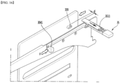
- FIG. 13 is a horizontal cross-sectional view of the connector according to the embodiment of the present disclosure.
- FIG. 14 is a horizontal cross-sectional view of the connector when the movable portion is pressed by the user, according to the embodiment of the present disclosure.
- the contact portion 3515 of the connector 35 may be urged in the left direction of the refrigerator 10 by the elastic member 3514.
- the contact portion 3515 may be urged in the left direction by the elastic member 3514 elastically supporting the side face of the body portion 3511 connected to the contact portion 3515.
- the contact portion 3515 may be laterally moved within the receiving space defined by the space defining portion 3552.
- the first inclined face 3516 of the contact portion 3515 may be in face-contact with the second inclined face 3544 of the protruding portion 3543.
- the movable portion 354 can be moved toward the front face of the refrigerator 10.
- the contact portion 3515 When, as described above, the contact portion 3515 is moved in the left direction by the elastic member 3514, the body portion 3511 connected to the contact portion 3515 is inserted into the receiving groove 339 of the sliding member 33. Thus, when the refrigerator door 12 is opened, the shelf 22 may be withdrawn forward together with the sliding member 33.
- the contact portion 3515 may be moved in the right direction in accordance with the backward movement of the movable portion 354.
- the contact portion 3515 may be moved in the right direction. Subsequently, when the protruding portion 3543 is moved to the rear end of the space defining portion 3552, the connecting unit 351 connected to the contact portion 3515 is separated from the receiving groove 339 of the sliding member 33. Therefore, even when the refrigerator door 12 is opened, the shelf 22 is not connected to the sliding member 33. Thus, the shelf 22 is not withdrawn forward together with the sliding member 33.
- the respective inclined contact faces 3516 and 3544 of the contact portion 3515 and the protruding portion 3543 are not in surface contact with each other. Rather, the parallel contact surfaces of the contact portion 3515 and the protruding portion 3543 are in surface contact with each other.
- the contact portion 3515 is no longer moved in the leftward direction. That is, when the movable portion 354 is moved to the end of the space defining portion 3552, the position of the contact portion 3515 may be held in a fixed manner.
- FIG. 15 shows a connector when the shelf automatic withdrawing function is activated according to the embodiment of the present disclosure.
- FIG. 16 shows the connector when the shelf automatic withdrawing function is deactivated.
- the body portion 3511 of the connecting unit 351 is moved in the left direction by the elastic member 3514. Then, the unit 351 is inserted into the receiving groove 339 of the sliding member 33. Thus, coupling between the connecting unit 351 and the sliding member 33 may allow the shelf 22 to be withdrawn forward as the refrigerator door 12 is opened.
- the user when the user wishes to disable the shelf automatic withdrawing function, the user presses the pressing portion 3541. Then, the movable portion 354 is moved rearward. Thus, the first inclined face 3516 of the contact portion 3515 slides along the second inclined face 3544 of the movable portion 354. The portion 3515 is moved by a predetermined distance d in the rightward direction. In addition, as the contact portion 3515 is moved in the right direction, the connecting unit 351 is separated from the receiving groove 339 of the sliding member 33.
- the shelf 22 is not withdrawn together with the sliding member 33 even when the sliding member 33 is withdrawn forward when the refrigerator door 12 is opened.
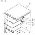
- FIG. 17 shows a shelf when a shelf automatic withdrawing function is disabled according to the embodiment of the present disclosure.
- a plurality of shelf assemblies 40 and 50 may be arranged on the refrigerator compartment 111 in a vertical direction.
- the plurality of shelf assemblies 40 and 50 include a first shelf assembly 40 mounted on the rear side of the refrigerator compartment 111 and a second shelf assembly 50 disposed below the first shelf assembly 40.
- the first shelf assembly 40 and the second shelf assembly 50 may respectively include a first shelf support arm 41 and a second shelf support arm 51 that are secured to the rear wall of the refrigerator compartment 111, and a first shelf 42 and a second shelf 52, which are installed so as to be movable in the anteroposterior direction on the shelf support arms, respectively.
- the user may also disable the shelf automatic withdrawing function for the desired shelf assembly among the shelf assemblies 40 and 50.
- the user may disable the shelf automatic withdrawing function for the first shelf assembly 40 via manipulation of the connector.
- the second shelf 52 of the second shelf assembly 50 is withdrawn forward as the refrigerator door 12 is opened.
- the first shelf 41 of the first shelf assembly 40 is not withdrawn forward as the refrigerator door 12 is opened.
- the coupling between the shelf and the withdrawing mechanism for withdrawing the shelf may be released by a simple operation using the pressing portion of the connector.
Landscapes
- Engineering & Computer Science (AREA)
- Chemical & Material Sciences (AREA)
- Combustion & Propulsion (AREA)
- Physics & Mathematics (AREA)
- Mechanical Engineering (AREA)
- Thermal Sciences (AREA)
- General Engineering & Computer Science (AREA)
- Refrigerator Housings (AREA)
- Devices That Are Associated With Refrigeration Equipment (AREA)
Claims (15)
- Kühlschrank (10), der aufweist:ein Gehäuse (11), das einen Aufbewahrungsraum definiert;eine Tür (12), die konfiguriert ist, mindestens einen Teil des Aufbewahrungsraums zu öffnen und zu schließen;eine Ablagebaugruppe (20), die einen Ablagehalterungsarm (21), der an der Innenseite des Gehäuses (11) befestigt ist, und eine Ablage (22) aufweist, die verschiebbar mit dem Ablagehalterungsarm (21) verbunden ist; undeinen Auszugsmechanismus (30), der konfiguriert ist, es zu ermöglichen, dass die Ablage (22) basierend darauf, dass die Tür (12) geöffnet wird, nach vorne gezogen wird, wobei der Auszugsmechanismus (30) aufweist:ein Schiebeelement (33), das an einer Seitenfläche des Gehäuses (11) angeordnet ist, das konfiguriert ist, sich in einer Vorwärts-Rückwärts-Richtung des Gehäuses (11) zu bewegen, und das eine Aufnahmenut (339) definiert,ein Verbindungselement (31), das die Tür (12) mit dem Schiebeelement (33) verbindet und das konfiguriert ist, das Schiebeelement (33) zu veranlassen, sich basierend auf der Bewegung der Tür (12) in der Vorwärts-Rückwärts-Richtung zu bewegen, wobei das Verbindungselement (31) ein mit der Tür (12) verbundenes vorderes Ende und ein mit dem Schiebeelement (33) verbundenes hinteres Ende aufweist, undeinen Verbindungsteil (35), der konfiguriert ist, das Schiebeelement (33) mit der Ablage (22) zu verbinden, wobei der Verbindungsteil (35) aufweist:eine Verbindungsstange (351), die aus der Ablagebaugruppe herausragt, die konfiguriert ist, selektiv in die Aufnahmenut (339) eingesetzt zu werden, und die konfiguriert ist, in einer seitlichen Richtung des Gehäuses (11) bewegt zu werden,eine Führung (352), die konfiguriert ist, einen Teil der Verbindungsstange (351) zu umgeben und die Verbindungsstange (351) so zu führen, dass sie sich in einer lateralen Richtung des Gehäuses (11) bewegt,eine Betätigungsstange (353), die konfiguriert ist, die Verbindungsstange (351) in das Innere der Führung (352) einzuführen, und die konfiguriert ist, sich in der Richtung von vorne nach hinten zu bewegen,wobei die Verbindungsstange (351) zur Seite der Ablagebaugruppe (20) vorsteht und selektiv in die Aufnahmenut (339) eingeführt wird; undwobei die Verbindungsstange (351) konfiguriert ist, in einem Aufnahmeraum (3523) aufgenommen zu werden, der in der Führung (352) definiert ist.
- Kühlschrank (10) nach Anspruch 1, wobei die Verbindungsstange (351) eine erste geneigte Fläche aufweist,
wobei die Betätigungsstange (353) eine zweite geneigte Fläche aufweist, die konfiguriert ist, die erste geneigte Fläche zu berühren. - Kühlschrank (10) nach Anspruch 1 oder 2, wobei die Verbindungsstange (351) aufweist:einen Körperabschnitt (3511) mit einem ersten Ende, das konfiguriert ist, in die Aufnahmenut (339) eingeführt zu werden;einen Kontaktabschnitt (3515), der an einer Bodenfläche des Körperabschnitts (3511) angeordnet ist und der die erste geneigte Fläche definiert, undein elastisches Element (3514), das konfiguriert ist, eine Kraft auf den Körperabschnitt (3511) zur Aufnahmenut (339) auszuüben, wobei das elastische Element (3514) ein erstes Ende, das in Kontakt mit einem zweiten Ende des Körperabschnitts (3511) steht, und ein zweites Ende aufweist, das an einer Innenseite der Führung (352) befestigt ist, die den Aufnahmeraum (3523) definiert.
- Kühlschrank (10) nach einem der Ansprüche 1 bis 3, wobei die Betätigungsstange (353) aufweist:einen beweglichen Abschnitt (354), der konfiguriert ist, sich in der Vorwärts-Rückwärts-Richtung zu bewegen; undeinen Führungsabschnitt (355), der an der Ablage (22) befestigt und konfiguriert ist, die Bewegung des beweglichen Abschnitts (354) zu führen.
- Kühlschrank (10) nach Anspruch 4, wobei der bewegliche Abschnitt (354) aufweist:einen Druckabschnitt (3541), der konfiguriert ist, von einem Benutzer ergriffen zu werden;einen Verlängerungsabschnitt (3542), der sich von dem Druckabschnitt (3541) nach hinten erstreckt; undeinen vorstehenden Abschnitt (3543), der an einem hinteren Ende des Verlängerungsabschnitts (3542) angeordnet ist und der die zweite geneigte Fläche definiert.
- Kühlschrank (10) nach Anspruch 5, wobei der Führungsabschnitt (355) einen Abdeckabschnitt (3551) aufweist, der den Verlängerungsabschnitt (3542) umgibt und der konfiguriert ist, die Bewegung des Verlängerungsabschnitts (3542) in der Vorwärts-Rückwärts-Richtung zu führen, und
wobei der Führungsabschnitt (355) einen hinteren Aufnahmeraum an einem hinteren Ende des Abdeckabschnitts (3551) definiert, wobei der hintere Aufnahmeraum den Kontaktabschnitt (3515) aufnimmt. - Kühlschrank (10) nach Anspruch 5 oder 6, wobei der vorstehende Abschnitt (3543) konfiguriert ist, sich basierend darauf, dass sich der bewegliche Abschnitt (354) in der Vorwärts-Rückwärts-Richtung bewegt, entlang der ersten geneigten Oberfläche in einem Zustand zu bewegen, in dem sich der Kontaktabschnitt (3515) lateral in den hinteren Aufnahmeraum bewegt.
- Kühlschrank (10) nach Anspruch 5 oder 6, wobei der Körperabschnitt (3511) konfiguriert ist, sich basierend darauf, dass sich der bewegliche Abschnitt (354) nach hinten bewegt, in eine Richtung zu bewegen, die das elastische Element (3514) zusammendrückt, und sich von der Aufnahmenut (339) in einem Zustand zu trennen, in dem sich der vorstehende Abschnitt (3543) relativ zum Kontaktabschnitt (3515) bewegt.
- Kühlschrank (10) nach einem der Ansprüche 4 bis 8, wobei das elastische Element (3514) konfiguriert ist, sich basierend darauf, dass sich der bewegliche Abschnitt (354) vorwärtsbewegt, eine Kraft auf den Körperabschnitt (3511) zur Aufnahmenut (339) auszuüben.
- Kühlschrank (10) nach einem der Ansprüche 1 bis 9, wobei die Führung (352) aufweist:ein unteres Gehäuse (3521), das die Verbindungsstange (351) lagert; undein oberes Gehäuse (3522), das das untere Gehäuse (3521) und die Verbindungsstange (351) abdeckt, undwobei der Aufnahmeraum (3523) zwischen dem unteren Gehäuse (3521) und dem oberen Gehäuse (3522) definiert ist.
- Kühlschrank (10) nach einem der Ansprüche 3 bis 10, wobei die Verbindungsstange (351) ferner einen Verlängerungsteil aufweist, der von einer Seitenfläche des Körperabschnitts (3511) vorsteht und der von dem elastischen Element (3514) umgeben ist.
- Kühlschrank (10) nach einem der Ansprüche 1 bis 11, wobei das Gehäuse (11) ein äußeres Gehäuse (116) und ein inneres Gehäuse (117) aufweist, das innerhalb des äußeren Gehäuses (116) angeordnet ist und den Aufbewahrungsraum definiert, und
wobei der Ablagehalterungsarm (21) an einer hinteren Fläche des inneren Gehäuses (117) befestigt ist. - Kühlschrank (10) nach Anspruch 12, wobei das innere Gehäuse (117) einen Führungsschlitz (341) an einer Position definiert, die einer Position der Ablage (22) entspricht, wobei der Führungsschlitz (341) eine vorbestimmte Länge in einer Längsrichtung der Ablage (22) hat, und
wobei die Verbindungsstange (351) konfiguriert ist, durch den Führungsschlitz (341) zu verlaufen und in die Aufnahmenut (339) eingeführt zu werden. - Kühlschrank (10) nach Anspruch 13, wobei die vorbestimmte Länge des Führungsschlitzes (341) kleiner ist als eine Länge der Ablage (22) in der Längsrichtung.
- Kühlschrank (10) nach einem der Ansprüche 1 bis 14, wobei die Verbindungsstange (351) konfiguriert ist, sich basierend darauf, dass sich die Betätigungsstange (353) zu einer hinteren Fläche des Gehäuses (11) bewegt, in einem Zustand, in dem sich die zweite geneigte Fläche entlang der ersten geneigten Fläche bewegt, von der Aufnahmenut (339) wegzubewegen.
Applications Claiming Priority (3)
| Application Number | Priority Date | Filing Date | Title |
|---|---|---|---|
| KR1020160046050A KR102447530B1 (ko) | 2016-04-15 | 2016-04-15 | 냉장고 |
| PCT/KR2017/004074 WO2017179950A2 (ko) | 2016-04-15 | 2017-04-14 | 냉장고 |
| EP17782705.2A EP3444548B1 (de) | 2016-04-15 | 2017-04-14 | Kühlschrank |
Related Parent Applications (1)
| Application Number | Title | Priority Date | Filing Date |
|---|---|---|---|
| EP17782705.2A Division EP3444548B1 (de) | 2016-04-15 | 2017-04-14 | Kühlschrank |
Publications (2)
| Publication Number | Publication Date |
|---|---|
| EP3812673A1 EP3812673A1 (de) | 2021-04-28 |
| EP3812673B1 true EP3812673B1 (de) | 2024-09-18 |
Family
ID=60042804
Family Applications (2)
| Application Number | Title | Priority Date | Filing Date |
|---|---|---|---|
| EP17782705.2A Active EP3444548B1 (de) | 2016-04-15 | 2017-04-14 | Kühlschrank |
| EP20206714.6A Active EP3812673B1 (de) | 2016-04-15 | 2017-04-14 | Kühlschrank |
Family Applications Before (1)
| Application Number | Title | Priority Date | Filing Date |
|---|---|---|---|
| EP17782705.2A Active EP3444548B1 (de) | 2016-04-15 | 2017-04-14 | Kühlschrank |
Country Status (5)
| Country | Link |
|---|---|
| US (2) | US10677518B2 (de) |
| EP (2) | EP3444548B1 (de) |
| KR (1) | KR102447530B1 (de) |
| ES (1) | ES2845075T3 (de) |
| WO (1) | WO2017179950A2 (de) |
Families Citing this family (6)
| Publication number | Priority date | Publication date | Assignee | Title |
|---|---|---|---|---|
| KR102447530B1 (ko) * | 2016-04-15 | 2022-09-26 | 엘지전자 주식회사 | 냉장고 |
| CN110198035A (zh) * | 2019-05-14 | 2019-09-03 | 合肥德盛电器有限责任公司 | 一种智能有源无功发生及谐波治理装置 |
| KR102903378B1 (ko) * | 2019-09-17 | 2025-12-24 | 엘지전자 주식회사 | 냉장고 |
| USD966352S1 (en) * | 2020-04-17 | 2022-10-11 | Samsung Electronics Co., Ltd. | Refrigerator |
| USD969888S1 (en) * | 2021-01-26 | 2022-11-15 | Lg Electronics Inc. | Refrigerator |
| CN114485021B (zh) * | 2022-01-04 | 2024-06-18 | 珠海格力电器股份有限公司 | 搁架的自动清洁装置、清洁方法、控制装置及冰箱 |
Citations (1)
| Publication number | Priority date | Publication date | Assignee | Title |
|---|---|---|---|---|
| US8960826B2 (en) * | 2012-06-21 | 2015-02-24 | Lg Electronics Inc. | Refrigerator |
Family Cites Families (28)
| Publication number | Priority date | Publication date | Assignee | Title |
|---|---|---|---|---|
| US1835847A (en) * | 1929-09-17 | 1931-12-08 | Arch G Chandler | Door shifted tray support for cabinets |
| US2095811A (en) * | 1934-03-30 | 1937-10-12 | Kelvinator Corp | Refrigerating apparatus |
| JPH08308659A (ja) * | 1995-05-17 | 1996-11-26 | Wakata Hiroshi | 引出を備える家具 |
| KR100203985B1 (ko) | 1995-07-20 | 1999-06-15 | 전주범 | 냉장고의 회동선반 |
| US6889237B2 (en) * | 2001-03-30 | 2005-05-03 | Intel Corporation | Two-dimensional pyramid filter architecture |
| KR20040059041A (ko) * | 2002-12-27 | 2004-07-05 | 엘지전자 주식회사 | 냉장고의 도어 설치구조 |
| KR100760403B1 (ko) * | 2006-09-07 | 2007-09-19 | 엘지전자 주식회사 | 냉장고용 아이스뱅크 출납장치 |
| KR100991274B1 (ko) * | 2008-07-30 | 2010-11-01 | 경상북도(수산자원개발연구소) | 대게의 치게 양식방법 |
| DE102009000855A1 (de) * | 2009-02-13 | 2010-08-26 | BSH Bosch und Siemens Hausgeräte GmbH | Kältegerät |
| KR20100130357A (ko) * | 2009-06-03 | 2010-12-13 | 엘지전자 주식회사 | 냉장고 |
| KR20110000660U (ko) * | 2009-07-14 | 2011-01-20 | 강완희 | Uv램프를 구비한 lcd 모니터 또는 노트북 컴퓨터 선반 |
| KR20110006604U (ko) * | 2009-12-24 | 2011-06-30 | 위니아만도 주식회사 | 냉장고 |
| CN102116554A (zh) * | 2010-01-04 | 2011-07-06 | Lg电子株式会社 | 电冰箱 |
| WO2011132974A2 (en) | 2010-04-21 | 2011-10-27 | Lg Electronics Inc. | Refrigerator |
| KR20120020850A (ko) * | 2010-08-31 | 2012-03-08 | 엘지전자 주식회사 | 선반 어셈블리가 구비된 냉장고 |
| US8960825B2 (en) | 2011-10-04 | 2015-02-24 | Lg Electronics Inc. | Refrigerator |
| SE537683C2 (sv) * | 2013-05-30 | 2015-09-29 | Ssab Technology Ab | Sandwichelement och lastgolv utformat som ett sådant |
| JP6299869B2 (ja) * | 2014-07-03 | 2018-03-28 | 三菱電機株式会社 | 絶縁ゲート型パワー半導体素子のゲート駆動回路 |
| WO2016068686A1 (ko) * | 2014-10-31 | 2016-05-06 | 엘지전자 주식회사 | 냉장고 |
| KR101720490B1 (ko) | 2014-12-31 | 2017-03-28 | 엘지전자 주식회사 | 냉장고 |
| KR101859037B1 (ko) * | 2015-02-13 | 2018-05-17 | 엘지전자 주식회사 | 냉장고 |
| EP3256800B1 (de) * | 2015-02-13 | 2024-08-21 | LG Electronics Inc. | Kühlschrank |
| KR102392664B1 (ko) * | 2015-02-13 | 2022-04-29 | 엘지전자 주식회사 | 냉장고 |
| KR101708698B1 (ko) * | 2015-02-13 | 2017-02-21 | 엘지전자 주식회사 | 냉장고 |
| KR102423614B1 (ko) * | 2016-02-05 | 2022-07-20 | 엘지전자 주식회사 | 냉장고 |
| US9726423B1 (en) * | 2016-04-06 | 2017-08-08 | Haier Us Appliance Solutions, Inc. | Sliding shelf assembly for a refrigerator appliance |
| KR102447530B1 (ko) * | 2016-04-15 | 2022-09-26 | 엘지전자 주식회사 | 냉장고 |
| DE102017205108A1 (de) * | 2017-03-27 | 2018-09-27 | BSH Hausgeräte GmbH | Haushaltskältegerätevorrichtung |
-
2016
- 2016-04-15 KR KR1020160046050A patent/KR102447530B1/ko active Active
-
2017
- 2017-04-14 EP EP17782705.2A patent/EP3444548B1/de active Active
- 2017-04-14 US US16/093,861 patent/US10677518B2/en active Active
- 2017-04-14 EP EP20206714.6A patent/EP3812673B1/de active Active
- 2017-04-14 WO PCT/KR2017/004074 patent/WO2017179950A2/ko not_active Ceased
- 2017-04-14 ES ES17782705T patent/ES2845075T3/es active Active
-
2020
- 2020-04-30 US US16/863,769 patent/US11041673B2/en active Active
Patent Citations (1)
| Publication number | Priority date | Publication date | Assignee | Title |
|---|---|---|---|---|
| US8960826B2 (en) * | 2012-06-21 | 2015-02-24 | Lg Electronics Inc. | Refrigerator |
Also Published As
| Publication number | Publication date |
|---|---|
| US20190107320A1 (en) | 2019-04-11 |
| US20200256615A1 (en) | 2020-08-13 |
| WO2017179950A3 (ko) | 2018-08-02 |
| KR102447530B1 (ko) | 2022-09-26 |
| US10677518B2 (en) | 2020-06-09 |
| EP3444548A2 (de) | 2019-02-20 |
| US11041673B2 (en) | 2021-06-22 |
| KR20170118371A (ko) | 2017-10-25 |
| EP3444548B1 (de) | 2020-12-02 |
| EP3444548A4 (de) | 2019-11-27 |
| EP3812673A1 (de) | 2021-04-28 |
| ES2845075T3 (es) | 2021-07-23 |
| WO2017179950A2 (ko) | 2017-10-19 |
Similar Documents
| Publication | Publication Date | Title |
|---|---|---|
| US11041673B2 (en) | Refrigerator | |
| EP2910879B1 (de) | Kühlschrank | |
| US10941973B2 (en) | Refrigerator | |
| EP2420776B1 (de) | Kühlschrank | |
| KR101708698B1 (ko) | 냉장고 | |
| US8052236B2 (en) | Refrigerator | |
| KR102026464B1 (ko) | 가변선반장치 및 이를 포함한 냉장고 | |
| US10393425B2 (en) | Refrigerator and door opening and closing apparatus for refrigerator | |
| EP3919708A1 (de) | Kühlschrank | |
| KR20170093521A (ko) | 냉장고 | |
| KR102470041B1 (ko) | 냉장고 | |
| KR102093435B1 (ko) | 냉장고 | |
| KR20190104109A (ko) | 냉장고 | |
| KR102111717B1 (ko) | 냉장고 | |
| KR102584693B1 (ko) | 냉장고 | |
| KR102093461B1 (ko) | 냉장고 | |
| KR102093456B1 (ko) | 냉장고 | |
| KR102093448B1 (ko) | 냉장고 | |
| KR20180028776A (ko) | 냉장고 | |
| KR20190104107A (ko) | 냉장고 | |
| KR20030060633A (ko) | 냉장고 | |
| KR20060066450A (ko) | 냉장고용 집출장치 |
Legal Events
| Date | Code | Title | Description |
|---|---|---|---|
| PUAI | Public reference made under article 153(3) epc to a published international application that has entered the european phase |
Free format text: ORIGINAL CODE: 0009012 |
|
| STAA | Information on the status of an ep patent application or granted ep patent |
Free format text: STATUS: REQUEST FOR EXAMINATION WAS MADE |
|
| 17P | Request for examination filed |
Effective date: 20201210 |
|
| AC | Divisional application: reference to earlier application |
Ref document number: 3444548 Country of ref document: EP Kind code of ref document: P |
|
| AK | Designated contracting states |
Kind code of ref document: A1 Designated state(s): AL AT BE BG CH CY CZ DE DK EE ES FI FR GB GR HR HU IE IS IT LI LT LU LV MC MK MT NL NO PL PT RO RS SE SI SK SM TR |
|
| RBV | Designated contracting states (corrected) |
Designated state(s): AL AT BE BG CH CY CZ DE DK EE ES FI FR GB GR HR HU IE IS IT LI LT LU LV MC MK MT NL NO PL PT RO RS SE SI SK SM TR |
|
| STAA | Information on the status of an ep patent application or granted ep patent |
Free format text: STATUS: EXAMINATION IS IN PROGRESS |
|
| 17Q | First examination report despatched |
Effective date: 20221123 |
|
| GRAP | Despatch of communication of intention to grant a patent |
Free format text: ORIGINAL CODE: EPIDOSNIGR1 |
|
| STAA | Information on the status of an ep patent application or granted ep patent |
Free format text: STATUS: GRANT OF PATENT IS INTENDED |
|
| INTG | Intention to grant announced |
Effective date: 20240425 |
|
| GRAS | Grant fee paid |
Free format text: ORIGINAL CODE: EPIDOSNIGR3 |
|
| GRAA | (expected) grant |
Free format text: ORIGINAL CODE: 0009210 |
|
| STAA | Information on the status of an ep patent application or granted ep patent |
Free format text: STATUS: THE PATENT HAS BEEN GRANTED |
|
| AC | Divisional application: reference to earlier application |
Ref document number: 3444548 Country of ref document: EP Kind code of ref document: P |
|
| AK | Designated contracting states |
Kind code of ref document: B1 Designated state(s): AL AT BE BG CH CY CZ DE DK EE ES FI FR GB GR HR HU IE IS IT LI LT LU LV MC MK MT NL NO PL PT RO RS SE SI SK SM TR |
|
| REG | Reference to a national code |
Ref country code: GB Ref legal event code: FG4D |
|
| REG | Reference to a national code |
Ref country code: CH Ref legal event code: EP |
|
| REG | Reference to a national code |
Ref country code: DE Ref legal event code: R096 Ref document number: 602017085002 Country of ref document: DE |
|
| REG | Reference to a national code |
Ref country code: IE Ref legal event code: FG4D |
|
| REG | Reference to a national code |
Ref country code: LT Ref legal event code: MG9D |
|
| PG25 | Lapsed in a contracting state [announced via postgrant information from national office to epo] |
Ref country code: NO Free format text: LAPSE BECAUSE OF FAILURE TO SUBMIT A TRANSLATION OF THE DESCRIPTION OR TO PAY THE FEE WITHIN THE PRESCRIBED TIME-LIMIT Effective date: 20241218 |
|
| PG25 | Lapsed in a contracting state [announced via postgrant information from national office to epo] |
Ref country code: GR Free format text: LAPSE BECAUSE OF FAILURE TO SUBMIT A TRANSLATION OF THE DESCRIPTION OR TO PAY THE FEE WITHIN THE PRESCRIBED TIME-LIMIT Effective date: 20241219 Ref country code: FI Free format text: LAPSE BECAUSE OF FAILURE TO SUBMIT A TRANSLATION OF THE DESCRIPTION OR TO PAY THE FEE WITHIN THE PRESCRIBED TIME-LIMIT Effective date: 20240918 |
|
| PG25 | Lapsed in a contracting state [announced via postgrant information from national office to epo] |
Ref country code: BG Free format text: LAPSE BECAUSE OF FAILURE TO SUBMIT A TRANSLATION OF THE DESCRIPTION OR TO PAY THE FEE WITHIN THE PRESCRIBED TIME-LIMIT Effective date: 20240918 |
|
| PG25 | Lapsed in a contracting state [announced via postgrant information from national office to epo] |
Ref country code: LV Free format text: LAPSE BECAUSE OF FAILURE TO SUBMIT A TRANSLATION OF THE DESCRIPTION OR TO PAY THE FEE WITHIN THE PRESCRIBED TIME-LIMIT Effective date: 20240918 |
|
| PG25 | Lapsed in a contracting state [announced via postgrant information from national office to epo] |
Ref country code: HR Free format text: LAPSE BECAUSE OF FAILURE TO SUBMIT A TRANSLATION OF THE DESCRIPTION OR TO PAY THE FEE WITHIN THE PRESCRIBED TIME-LIMIT Effective date: 20240918 |
|
| REG | Reference to a national code |
Ref country code: NL Ref legal event code: MP Effective date: 20240918 |
|
| PG25 | Lapsed in a contracting state [announced via postgrant information from national office to epo] |
Ref country code: RS Free format text: LAPSE BECAUSE OF FAILURE TO SUBMIT A TRANSLATION OF THE DESCRIPTION OR TO PAY THE FEE WITHIN THE PRESCRIBED TIME-LIMIT Effective date: 20241218 |
|
| PG25 | Lapsed in a contracting state [announced via postgrant information from national office to epo] |
Ref country code: RS Free format text: LAPSE BECAUSE OF FAILURE TO SUBMIT A TRANSLATION OF THE DESCRIPTION OR TO PAY THE FEE WITHIN THE PRESCRIBED TIME-LIMIT Effective date: 20241218 Ref country code: NO Free format text: LAPSE BECAUSE OF FAILURE TO SUBMIT A TRANSLATION OF THE DESCRIPTION OR TO PAY THE FEE WITHIN THE PRESCRIBED TIME-LIMIT Effective date: 20241218 Ref country code: LV Free format text: LAPSE BECAUSE OF FAILURE TO SUBMIT A TRANSLATION OF THE DESCRIPTION OR TO PAY THE FEE WITHIN THE PRESCRIBED TIME-LIMIT Effective date: 20240918 Ref country code: HR Free format text: LAPSE BECAUSE OF FAILURE TO SUBMIT A TRANSLATION OF THE DESCRIPTION OR TO PAY THE FEE WITHIN THE PRESCRIBED TIME-LIMIT Effective date: 20240918 Ref country code: GR Free format text: LAPSE BECAUSE OF FAILURE TO SUBMIT A TRANSLATION OF THE DESCRIPTION OR TO PAY THE FEE WITHIN THE PRESCRIBED TIME-LIMIT Effective date: 20241219 Ref country code: FI Free format text: LAPSE BECAUSE OF FAILURE TO SUBMIT A TRANSLATION OF THE DESCRIPTION OR TO PAY THE FEE WITHIN THE PRESCRIBED TIME-LIMIT Effective date: 20240918 Ref country code: BG Free format text: LAPSE BECAUSE OF FAILURE TO SUBMIT A TRANSLATION OF THE DESCRIPTION OR TO PAY THE FEE WITHIN THE PRESCRIBED TIME-LIMIT Effective date: 20240918 |
|
| REG | Reference to a national code |
Ref country code: AT Ref legal event code: MK05 Ref document number: 1725006 Country of ref document: AT Kind code of ref document: T Effective date: 20240918 |
|
| PG25 | Lapsed in a contracting state [announced via postgrant information from national office to epo] |
Ref country code: NL Free format text: LAPSE BECAUSE OF FAILURE TO SUBMIT A TRANSLATION OF THE DESCRIPTION OR TO PAY THE FEE WITHIN THE PRESCRIBED TIME-LIMIT Effective date: 20240918 |
|
| PG25 | Lapsed in a contracting state [announced via postgrant information from national office to epo] |
Ref country code: IS Free format text: LAPSE BECAUSE OF FAILURE TO SUBMIT A TRANSLATION OF THE DESCRIPTION OR TO PAY THE FEE WITHIN THE PRESCRIBED TIME-LIMIT Effective date: 20250118 Ref country code: PT Free format text: LAPSE BECAUSE OF FAILURE TO SUBMIT A TRANSLATION OF THE DESCRIPTION OR TO PAY THE FEE WITHIN THE PRESCRIBED TIME-LIMIT Effective date: 20250120 |
|
| PG25 | Lapsed in a contracting state [announced via postgrant information from national office to epo] |
Ref country code: RO Free format text: LAPSE BECAUSE OF FAILURE TO SUBMIT A TRANSLATION OF THE DESCRIPTION OR TO PAY THE FEE WITHIN THE PRESCRIBED TIME-LIMIT Effective date: 20240918 Ref country code: SM Free format text: LAPSE BECAUSE OF FAILURE TO SUBMIT A TRANSLATION OF THE DESCRIPTION OR TO PAY THE FEE WITHIN THE PRESCRIBED TIME-LIMIT Effective date: 20240918 |
|
| PG25 | Lapsed in a contracting state [announced via postgrant information from national office to epo] |
Ref country code: ES Free format text: LAPSE BECAUSE OF FAILURE TO SUBMIT A TRANSLATION OF THE DESCRIPTION OR TO PAY THE FEE WITHIN THE PRESCRIBED TIME-LIMIT Effective date: 20240918 |
|
| PG25 | Lapsed in a contracting state [announced via postgrant information from national office to epo] |
Ref country code: AT Free format text: LAPSE BECAUSE OF FAILURE TO SUBMIT A TRANSLATION OF THE DESCRIPTION OR TO PAY THE FEE WITHIN THE PRESCRIBED TIME-LIMIT Effective date: 20240918 Ref country code: EE Free format text: LAPSE BECAUSE OF FAILURE TO SUBMIT A TRANSLATION OF THE DESCRIPTION OR TO PAY THE FEE WITHIN THE PRESCRIBED TIME-LIMIT Effective date: 20240918 |
|
| PG25 | Lapsed in a contracting state [announced via postgrant information from national office to epo] |
Ref country code: PL Free format text: LAPSE BECAUSE OF FAILURE TO SUBMIT A TRANSLATION OF THE DESCRIPTION OR TO PAY THE FEE WITHIN THE PRESCRIBED TIME-LIMIT Effective date: 20240918 Ref country code: CZ Free format text: LAPSE BECAUSE OF FAILURE TO SUBMIT A TRANSLATION OF THE DESCRIPTION OR TO PAY THE FEE WITHIN THE PRESCRIBED TIME-LIMIT Effective date: 20240918 |
|
| PG25 | Lapsed in a contracting state [announced via postgrant information from national office to epo] |
Ref country code: IT Free format text: LAPSE BECAUSE OF FAILURE TO SUBMIT A TRANSLATION OF THE DESCRIPTION OR TO PAY THE FEE WITHIN THE PRESCRIBED TIME-LIMIT Effective date: 20240918 Ref country code: SK Free format text: LAPSE BECAUSE OF FAILURE TO SUBMIT A TRANSLATION OF THE DESCRIPTION OR TO PAY THE FEE WITHIN THE PRESCRIBED TIME-LIMIT Effective date: 20240918 |
|
| REG | Reference to a national code |
Ref country code: DE Ref legal event code: R097 Ref document number: 602017085002 Country of ref document: DE |
|
| PGFP | Annual fee paid to national office [announced via postgrant information from national office to epo] |
Ref country code: DE Payment date: 20250305 Year of fee payment: 9 |
|
| PG25 | Lapsed in a contracting state [announced via postgrant information from national office to epo] |
Ref country code: DK Free format text: LAPSE BECAUSE OF FAILURE TO SUBMIT A TRANSLATION OF THE DESCRIPTION OR TO PAY THE FEE WITHIN THE PRESCRIBED TIME-LIMIT Effective date: 20240918 |
|
| PLBE | No opposition filed within time limit |
Free format text: ORIGINAL CODE: 0009261 |
|
| STAA | Information on the status of an ep patent application or granted ep patent |
Free format text: STATUS: NO OPPOSITION FILED WITHIN TIME LIMIT |
|
| 26N | No opposition filed |
Effective date: 20250619 |
|
| PG25 | Lapsed in a contracting state [announced via postgrant information from national office to epo] |
Ref country code: SE Free format text: LAPSE BECAUSE OF FAILURE TO SUBMIT A TRANSLATION OF THE DESCRIPTION OR TO PAY THE FEE WITHIN THE PRESCRIBED TIME-LIMIT Effective date: 20240918 |
|
| REG | Reference to a national code |
Ref country code: CH Ref legal event code: H13 Free format text: ST27 STATUS EVENT CODE: U-0-0-H10-H13 (AS PROVIDED BY THE NATIONAL OFFICE) Effective date: 20251125 |
|
| PG25 | Lapsed in a contracting state [announced via postgrant information from national office to epo] |
Ref country code: LU Free format text: LAPSE BECAUSE OF NON-PAYMENT OF DUE FEES Effective date: 20250414 |
|
| PG25 | Lapsed in a contracting state [announced via postgrant information from national office to epo] |
Ref country code: MC Free format text: LAPSE BECAUSE OF FAILURE TO SUBMIT A TRANSLATION OF THE DESCRIPTION OR TO PAY THE FEE WITHIN THE PRESCRIBED TIME-LIMIT Effective date: 20240918 |
|
| GBPC | Gb: european patent ceased through non-payment of renewal fee |
Effective date: 20250414 |
|
| REG | Reference to a national code |
Ref country code: BE Ref legal event code: MM Effective date: 20250430 |
|
| PG25 | Lapsed in a contracting state [announced via postgrant information from national office to epo] |
Ref country code: GB Free format text: LAPSE BECAUSE OF NON-PAYMENT OF DUE FEES Effective date: 20250414 |
|
| PG25 | Lapsed in a contracting state [announced via postgrant information from national office to epo] |
Ref country code: FR Free format text: LAPSE BECAUSE OF NON-PAYMENT OF DUE FEES Effective date: 20250430 |
|
| PG25 | Lapsed in a contracting state [announced via postgrant information from national office to epo] |
Ref country code: BE Free format text: LAPSE BECAUSE OF NON-PAYMENT OF DUE FEES Effective date: 20250430 |
|
| PG25 | Lapsed in a contracting state [announced via postgrant information from national office to epo] |
Ref country code: CH Free format text: LAPSE BECAUSE OF NON-PAYMENT OF DUE FEES Effective date: 20250430 |