EP3812271B1 - System zur wiederherstellung eines zu tragenden luftfahrzeugs - Google Patents
System zur wiederherstellung eines zu tragenden luftfahrzeugs Download PDFInfo
- Publication number
- EP3812271B1 EP3812271B1 EP20186917.9A EP20186917A EP3812271B1 EP 3812271 B1 EP3812271 B1 EP 3812271B1 EP 20186917 A EP20186917 A EP 20186917A EP 3812271 B1 EP3812271 B1 EP 3812271B1
- Authority
- EP
- European Patent Office
- Prior art keywords
- receiver
- aircraft
- attachment
- carrier
- finger
- Prior art date
- Legal status (The legal status is an assumption and is not a legal conclusion. Google has not performed a legal analysis and makes no representation as to the accuracy of the status listed.)
- Active
Links
Images


Classifications
-
- B—PERFORMING OPERATIONS; TRANSPORTING
- B64—AIRCRAFT; AVIATION; COSMONAUTICS
- B64D—EQUIPMENT FOR FITTING IN OR TO AIRCRAFT; FLIGHT SUITS; PARACHUTES; ARRANGEMENT OR MOUNTING OF POWER PLANTS OR PROPULSION TRANSMISSIONS IN AIRCRAFT
- B64D1/00—Dropping, ejecting, releasing or receiving articles, liquids, or the like, in flight
- B64D1/22—Taking-up articles from earth's surface
-
- B—PERFORMING OPERATIONS; TRANSPORTING
- B64—AIRCRAFT; AVIATION; COSMONAUTICS
- B64D—EQUIPMENT FOR FITTING IN OR TO AIRCRAFT; FLIGHT SUITS; PARACHUTES; ARRANGEMENT OR MOUNTING OF POWER PLANTS OR PROPULSION TRANSMISSIONS IN AIRCRAFT
- B64D1/00—Dropping, ejecting, releasing or receiving articles, liquids, or the like, in flight
- B64D1/02—Dropping, ejecting, or releasing articles
- B64D1/08—Dropping, ejecting, or releasing articles the articles being load-carrying devices
- B64D1/12—Releasing
-
- B—PERFORMING OPERATIONS; TRANSPORTING
- B64—AIRCRAFT; AVIATION; COSMONAUTICS
- B64D—EQUIPMENT FOR FITTING IN OR TO AIRCRAFT; FLIGHT SUITS; PARACHUTES; ARRANGEMENT OR MOUNTING OF POWER PLANTS OR PROPULSION TRANSMISSIONS IN AIRCRAFT
- B64D5/00—Aircraft transported by aircraft, e.g. for release or reberthing during flight
-
- B—PERFORMING OPERATIONS; TRANSPORTING
- B64—AIRCRAFT; AVIATION; COSMONAUTICS
- B64U—UNMANNED AERIAL VEHICLES [UAV]; EQUIPMENT THEREFOR
- B64U10/00—Type of UAV
- B64U10/10—Rotorcrafts
- B64U10/13—Flying platforms
-
- B—PERFORMING OPERATIONS; TRANSPORTING
- B64—AIRCRAFT; AVIATION; COSMONAUTICS
- B64U—UNMANNED AERIAL VEHICLES [UAV]; EQUIPMENT THEREFOR
- B64U20/00—Constructional aspects of UAVs
- B64U20/80—Arrangement of on-board electronics, e.g. avionics systems or wiring
- B64U20/87—Mounting of imaging devices, e.g. mounting of gimbals
-
- B—PERFORMING OPERATIONS; TRANSPORTING
- B64—AIRCRAFT; AVIATION; COSMONAUTICS
- B64U—UNMANNED AERIAL VEHICLES [UAV]; EQUIPMENT THEREFOR
- B64U50/00—Propulsion; Power supply
- B64U50/30—Supply or distribution of electrical power
-
- B—PERFORMING OPERATIONS; TRANSPORTING
- B64—AIRCRAFT; AVIATION; COSMONAUTICS
- B64U—UNMANNED AERIAL VEHICLES [UAV]; EQUIPMENT THEREFOR
- B64U70/00—Launching, take-off or landing arrangements
- B64U70/20—Launching, take-off or landing arrangements for releasing or capturing UAVs in flight by another aircraft
Definitions
- the present invention relates to a recovery or even release system for carrying an aircraft with another aircraft.
- the invention therefore lies in the technical field of aircraft.
- helicopters or equivalents have great autonomy but are bulky, expensive and subject to navigation constraints aimed at ensuring the safety of their occupants. Furthermore, a helicopter cannot operate in certain airspaces to preserve the safety of its occupants, for example when the terrain is likely to lead to an accident or even when the atmosphere is contaminated in particular by chemically dangerous elements, bacteria or still radioactive elements following an incident.
- drones are unmanned aircraft with limited autonomy. However, some drones have a limited footprint allowing them to operate near dangerous terrain. Drones can be piloted by a remote human pilot or by an on-board or remote autopilot, for example to operate in a polluted environment dangerous for humans.
- an aircraft called for convenience “carrying aircraft” can carry in flight another aircraft called for convenience “carrying aircraft”.
- a helicopter can be equipped with a drone that can be released and/or recovered in flight.
- the drone can be an extension of the carrier aircraft.
- a helicopter can cover a relatively long distance to bring a drone as close as possible to an area to be explored where an accident has occurred. This area may possibly be inaccessible to the helicopter for reasons of safety of the people embarked in this helicopter, questions of accessibility, etc.
- the drone is then released to explore the area in a secure manner and is eventually recovered by the helicopter.
- recovering the drone with the helicopter can be interesting, for example to resupply it with fuel or electrical energy with recharging on board during the mission, or even to recover equipment transported by this drone.
- the document WO2008/089432 shows an aircraft dropping a drone attached to a parachute. After release, the parachute detaches from the drone and the drone becomes autonomous.
- the state of the art also includes the documents EP2103518A2 , US2006/249623A1 , FR2941922A1 , US3389880A , DE3206299A1 , US 3249322 A , CN 108 945 531 A , US 9448562 B1 And US4753400A .
- the document US 3249322 describes a system for linking two planes.
- This system comprises a receiving member arranged at the end of a wing of a first aircraft.
- This receiving member is configured to cooperate with a dome and a rod arranged at the end of a wing of another aircraft.
- the document CN 108 945 531 A describes a satellite recovery system.
- the document FR 2974786 describes a device for releasing and recovering a drone capable of being attached to an aircraft.
- This device comprises a means of receiving a drone, this receiving means being provided with a means of securing/detaching the drone, the receiving means being secured to a flared guiding means to guide the drone towards the means of reception.
- the object of the present invention is therefore to propose a system for recovering or even releasing a drone, simple to implement, and for example applicable to a helicopter type aircraft.
- the invention aims at a recovery system for at least recovering, or even releasing, in flight an aircraft to be carried from a carrier aircraft, the recovery system comprising a receiver capable of being carried by the carrier aircraft and a hook capable of to be carried by the aircraft to be carried, said receiver having an internal volume opening onto an external environment via a passage surface, said receiver comprising a hollow guide section, said guide section being flared.
- the aircraft to be carried is an aircraft without an onboard pilot.
- the carrier aircraft is an aircraft capable of flying at “low speed” and for example at less than 50 knots and/or comprising a rotating wing.
- the carrier aircraft may be an aircraft equipped with at least one human and/or automatic pilot.
- the system may optionally include one or more of the following features.
- the hook may comprise a flared connection section capable of being contained at least partially in said internal volume, the recovery system comprising a fixing device reversibly fixing the hook to the receiver, for example under conditions predetermined.
- predetermined conditions may include a predetermined position or a predetermined envelope of positions of the catcher relative to the receiver.
- connection section or even the hook are inscribed in a hooking volume capable of being contained entirely in the internal volume of the receiver due to their volumes and their shapes.
- the receiver can be attached to the carrier aircraft.
- the receiver may comprise a fixation arranged for example outside the internal volume of the receiver.
- This attachment can be attached to the carrier aircraft.
- the receiver can be attached to a cable which is attached to a jib or even to a winch... If necessary, the usual winch interfaces can be retained in order to leave all its mission versatility to the carrier aircraft.
- the receiver can represent ballast aimed at keeping the cable substantially taut to, for example, prevent the cable from rising towards the carrier aircraft following a release.
- the receiver and the hook can each have a section having a flared shape. This shape makes it possible to optimize the capture of the catcher by the receiver under numerous flight conditions.
- the receiver can capture an eye-catcher from a drone during a hovering flight phase of the carrier aircraft but also during an advancing flight.
- the recovery of a drone is carried out during a translation flight of the carrier aircraft to prevent a cable carrying the receiver from bouncing around.
- the attitude of the aircraft to be carried equipped with the hook can be controlled to be substantially parallel to the passage surface.
- connection section and the guide section each have a shape which flares substantially in a direction going from the aircraft towards the ground and for example conical or frustoconical, the shape of the connection section being smaller than the shape of the guide section.
- the receiver may comprise at least one orifice passing right through a wall of this receiver, this orifice putting said external medium and said internal volume into fluid communication.
- Such an orifice can in particular allow external air to flow from the external environment towards the internal volume in order to stabilize the receiver in flight.
- the guide section is asymmetrical.
- the guide section has an asymmetrical shape in particular devoid of symmetry of revolution unlike a strictly conical or frustoconical shape to take into consideration a tilting of the receiver during an advancing flight.
- An asymmetrical shape can tend to limit the risk of the receiver swinging during forward flight.
- the guide section may have revolution symmetry.
- the recovery system can be dimensioned to allow a predetermined drift of the receiver in forward flight which forces the possible cable and the receiver to follow a “clean” trajectory, namely with a rotational movement along the axis of the winch cable possibly restricted to a few degrees and/or with lateral or front-to-back sway reduced to a few degrees.
- the receiver may comprise a centering portion secured to a receiving vertex of the guide section, said catcher comprising a centering finger possibly secured to a connection vertex of said connection section, the centering finger being configured to penetrate said centering portion.
- the hook therefore comprises a centering finger of a shape substantially complementary to the centering portion. From then on, the hook can move, or even slide, in the guide section until the centering finger takes its place in the centering portion. When the centering finger is positioned in the centering portion, the hook is correctly positioned within the receiver at least horizontally.
- the centering portion comprises a ring.
- the receiver may have a bell-shaped centering portion which overcomes the guide section, the bell partially delimiting the internal volume.
- the internal volume can be broken down into a lower volume delimited by the guide section and an upper volume delimited by the bell.
- the bell optionally allows the hanger to be positioned horizontally via the edges of this bell or even vertically via the bottom of the bell.
- said hook can be integral with a mast configured to be attached to the aircraft to be carried, said mast comprising a segment arranged outside of said receiver when said hook is secured to the receiver.
- the mast makes it possible to move the aircraft to be carried away from the receiver to avoid any contact between this aircraft to be carried and the receiver.
- the mast extends in an extension direction over a mast length greater than a height of the receiver in said extension direction.
- the direction of extension may represent an axis of symmetry of revolution of a centering portion of the receiver.
- At least said hook or said receiver may comprise at least one buffer member configured to limit the consequences of contact between the hook and the receiver.
- the catcher and/or the receiver may include at least one buffer member.
- the buffer member may comprise a block made of an elastic material, elastomer for example.
- the buffer member can be fixed to an internal face of the receiver delimiting the internal volume or to an external face of the hook.
- said fixing device may comprise at least one magnetization zone secured to the catcher or the receiver, said fixing device having at least one reversible magnet secured to the catcher or the receiver devoid of the magnetization zone. magnetization, said at least one reversible magnet being capable of being magnetized or not magnetized to said at least one magnetization zone on command.
- the receiver can therefore have a magnetization zone which can be magnetized to at least one reversible magnet of the hook to fix this hook to the receiver on the order of a control member.
- the control of at least certain reversible magnets can be done manually through an operator present on the ground or on board the carrier aircraft, for example, but can also be issued in total autonomy by a computer possibly following a position detection by a positioning system.
- a buffer member may in particular be of interest in the case of the use of reversible magnets generating significant magnetic fields capable of violently bringing the catcher closer to the receiver.
- this at least one reversible magnet may comprise at least one normally open magnet which is magnetizable in the magnetization zone except in the event of an electrical failure, said at least one reversible magnet comprising at least one normally open magnet. closed which is magnetizable to the magnetization zone by an electrically autonomous module in the event of detection of an electrical failure, said at least one normally open reversible magnet not cooperating with said module.
- magnetizable subsequently qualifies a reversible magnet generating a magnetic field in a direction making it possible to magnetize this reversible magnet to the magnetization zone.
- Each reversible magnet can, for example, include an electromagnet system generating a magnetic field with variable orientation.
- a reversible magnet can be magnetizable or non-magnetizable at the magnetization zone depending on the orientation of the magnetic field that it generates.
- each reversible magnet may include a system known under the trade name “OpenGrab EPM V3 R5C” and marketed by “nicadrone”.
- At least one reversible magnet can be magnetized during a docking phase of the catcher to the receiver.
- An electrical source of such a network can electrically power each normally open reversible magnet directly or indirectly. This electrical source can make it possible, under normal conditions, to magnetize normally open magnets if necessary in order to secure a catcher to a receiver.
- the electrical power source may include at least one electrical source of the aircraft to be worn when the reversible magnets are on the hook.
- the source of electrical energy may include a cell, a battery, an electrical generator, etc.
- the module connected to the normally closed magnets may include its own reserve of electrical energy, such as a cell, a battery, an electric generator
- the recovery system may include at least one switch to inhibit said at least one normally closed magnet and/or said at least one normally open magnet.
- inhibit means that the inhibited reversible magnet does not produce a magnetic field allowing it to be magnetized to the magnetization zone.
- the switch can either be controlled by a computer of the aircraft to be carried according to a memorized law or an equivalent or controlled by an off-board pilot for example.
- a switch can cut an electrical line leading to a reversible magnet or can generate an order transmitted to said module.
- each switch can thus be activated to inhibit the reversible magnets. Consequently, the normally open and normally closed magnets are for example adjusted to each generate a magnetic field which does not allow it to be magnetized to the magnetization zone, independently of the position of the catcher relative to the receiver.
- each switch can be used to activate the magnetization system.
- normally open magnets When the catcher can be docked to the receiver, the normally open magnets are commanded to change the orientation of their magnetic fields so that they can be attached to the magnetization area. Conversely, normally closed magnets do not receive any command and remain non-magnetizable in the magnetization zone.
- the module can detect such a failure, for example by detecting the absence of an electric current at its terminals.
- the module being electrically independent, this module controls the normally closed magnets to make them magnetizable in the magnetization zone. For example, the module transmits an electrical signal to each normally closed magnet for this purpose.
- the fixing device may comprise at least one locking finger movable relative to the guide section, said locking finger being movable between a free position in which the locking finger does not hinder the hook and a blocking position in which said hook is held at least by the blocking finger.
- the blocking finger(s) are carried by the receiver.
- the locking finger(s) are each articulated to a support of the receiver by a connection, and for example by a pivot connection.
- blocking finger designates an organ capable of blocking the hook, for example by interference of shape.
- a locking finger can take the form of an arm capable of bracing or of a hook capable of being inserted into a groove or an equivalent.
- the guide section may include a cutout using a locking finger, each locking finger passing through the cutout at least in the locking position in which the locking finger jams the hook.
- a cutout can take the form of a aforementioned orifice.
- Each blocking finger can cooperate with the receiver to form a clamp to provide a positive stop between the receiver and the catcher.
- Each locking finger can be motorized or mechanically controlled by the hook itself.
- the blocking finger can be mechanically controlled by the hook at least to move from the free position to the blocking position, said blocking finger being connected to a piston movable in translation so that a translation of the piston induced by the hook generates a rotation of the blocking finger.
- An example of a fixing device thus comprises a piston pushed by the hook.
- This piston can be mechanically connected to at least one locking finger in order to directly or indirectly tilt this locking finger.
- the translation of the piston induces the passage of each locking finger through the receiver and in particular the guide section to lock the hook to the receiver.
- this device can be dimensioned to pinch the hook after the implementation of the magnetizable members.
- the locking fingers can be unlocked by a human operator present in the carrying aircraft, and/or by actuators and possibly the same actuators which made it possible to place the locking fingers in the blocking position and/or following an action by the aircraft to be carried.
- a blocking finger can take the form of a movable hook, for example in rotation, to be inserted into a groove of the centering finger in order to block the hook vertically and/or horizontally.
- a hook can be controlled by a motor or mechanically without a motor and for example by the catcher.
- said recovery system may comprise at least one positioning device generating a signal which varies as a function of a relative position of the catcher relative to the receiver.
- Such a positioning device can provide assistance, in piloting the aircraft to be carried, to a remote human pilot or to an automatic pilot of the aircraft to be carried.
- the positioning device can also control the fixing system as soon as the hook is correctly positioned.
- a positioning computer can, from a certain distance, control progressive or substantially instantaneous magnetization of the aforementioned reversible magnets.
- the receiver and/or the catcher may have areas reserved for integrating various sensors of the positioning device.
- the positioning device may comprise at least one camera and/or at least one positioning calculator and/or at least one target carried by the receiver.
- the positioning device may include a camera carried by the catcher as well as a positioning calculator connected to said camera and at least one target carried by the receiver.
- the camera can, for example, be arranged, if necessary, on the centering finger of the catcher.
- the positioning calculator can apply known algorithms to determine the position of the hook relative to the receiver using images of the target captured by the camera. For example, an algorithm known under the English expression “vision computing” with OPEN CV or even a neural network of the type known under the expression “Deep learning” can be used to recognize the presence of the catchy and trigger the lock order.
- the target may comprise at least one geometric symbol and possibly at least one circle, the positioning calculator determining the position of the catcher according to the shape of the symbol captured with the camera with regard to the circle theoretically observed when the eye-catching is correctly positioned.
- the literature details such a process.
- the receiver may include a camera evaluating the position of the catcher.
- a positioning calculator uses the images transmitted by the camera to determine whether a centering finger of the catcher has passed through a centering orifice of the receiver and accordingly control the movement of each blocking finger. “Computer vision” or “deep learning” type algorithms are possible, for example.
- the positioning device may include a proximity sensor.
- a proximity sensor can for example include an ultrasonic system, a hall effect sensor, a push button, etc.
- the receiver and/or the catcher and/or the aircraft to be worn may comprise one or more inertial units
- a positioning device can where appropriate be connected to the switch controlling the reversible magnets.
- the invention in addition to a recovery system, relates to an assembly provided with a carrier aircraft and an aircraft to be carried, the receiver being attached to the carrier aircraft and the hook being attached to the aircraft to be carried.
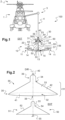
- FIG. 1 presents a recovery system 20 according to the invention.
- the figure 1 illustrates an assembly 100 comprising a carrier aircraft 1 and a carrier aircraft 10 cooperating with such a recovery system 20.
- the carrier aircraft 1 comprises a rotary wing 2.
- the figure 1 thus illustrates a helicopter but the carrier aircraft 1 could be of another type.
- aircraft 1 could also be an airplane, a rotorcraft, etc.
- the wearable aircraft 10 illustrated is a drone, namely an aircraft without an onboard human pilot.
- This drone comprises for example one or more rotors 11 rotated by motors 14.
- the motors 14 can be of all types and in particular electric motors connected to an electrical source 15 of the aircraft to be carried 10.
- this source electric 15 comprises at least one cell, at least one battery, at least one electric generator, etc.
- a control system comprising a pilot on-board automatic 13 and/or remotely controlled components can for example control the motors 14 to pilot the aircraft to be carried 10 in the usual manner.
- the recovery system 20 allows the carrier aircraft 1 to seize the aircraft to be carried 10 in flight and/or to release it in flight.
- the aircraft to be carried 10 and the recovery system 20 are possibly enlarged on the figure 1 relative to the carrier aircraft 1.
- the recovery system 20 comprises a first sub-assembly called for convenience "receiver 30" which is intended to be attached to the carrier aircraft 1.
- the receiver 30 can include a fixing called “fixing reception 40 "for convenience to be attached to the carrier aircraft 1.
- the carrier aircraft 1 may comprise a winch 3 carrying a winch cable 4.
- the receiver 30 can then be attached to the winch cable 4.
- the receiving attachment 40 may have a ring or equivalent attached to a hook 5 of the winch cable 4.
- the winch 3 then makes it possible to bring the receiver 30 closer or further away from the cell of the carrier aircraft 1.
- this cable 4 can have, outside the winch 3, a relatively large extension length so that the evolutions of the aircraft to be carried 10 are little disturbed by the air flow passing through the rotating wing 2.
- the receiver 30 may further include one or more handles 300 so that an operator can grip it more easily.
- the recovery system 20 comprises a second sub-assembly called for convenience "hook 50" intended to be secured to the aircraft to be carried 10.
- the hook 50 can be extended in elevation by a mast 55 fixed to the aircraft to carry 10 per a usual fixing member 57.
- the mast 55 is screwed to a support of the aircraft to be carried 10 in order to be secured to this aircraft to be carried 10.
- the mast 55 is dimensioned to present a segment 56 moving the aircraft to be carried 10 away from the receiver 30. Such a segment 56 extends at least partially outside the receiver 30.
- the recovery system 20 comprises a fixing device 60 having in particular the function of reversibly fixing the hook 50 to the receiver 30.
- the fixing device 60 can be controlled by a remote human operator and/or can be controlled automatically via various sensors and the like.
- the fixing device 60 can attach the hook 50 to the receiver 30 when the hook 50 is close to the receiver 30, namely in a predetermined envelope of positions relative to the receiver 30.
- the aircraft carry 10 is controlled to approach the hook 50 of the receiver 30 then the fixing device 60 secures the hook 50 to the receiver 30 when the hook 50 is in an appropriate position relative to the receiver 30.
- the aircraft to carry 10 is thus carried by the carrier aircraft 1 via the hook 50 and the receiver 30. This operation is reversible, the receiver 30 being able to release the hook 50 as is or possibly after an operation carried out by an operator, an actuator or even the aircraft to be carried 10.
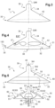
- the receiver 30 comprises an empty internal volume 38 in fluid communication with an external medium EXT at least via a passage surface 41. Therefore, the catcher 50 can penetrate into the internal volume 38 via this passage surface 41. Eye-catching 50 can also present a volume capable of being inscribed in the internal volume 38 in multiple ways.
- the receiver 30 comprises a flared guide section 31 at least partially delimiting the internal volume 38.
- This guide section 31 comprises a wall 42 provided with an internal face 32 at least partially delimiting the internal volume 38 and an external face 33 in contact with the external environment EXT.
- the flared guide section 31 has a shape extending from an annular receiving vertex 34 towards an annular receiving base 35 in an elevation direction DIR, the vertex having a radius less than a radius of the base.
- the receiving base 35 can be extended by another section opening onto the passage surface 41 or can open onto this passage surface 41 according to the example of the figure 2 .
- the guide section 31 may have a conical or frustoconical shape and/or, in an example which does not fall within the scope of the appended claims, may have a symmetry of revolution around the direction in elevation DIR.
- the guide section 31 is asymmetrical.
- the receiver 30 may comprise at least one orifice 37 putting the external environment EXT and the internal volume 38 into fluid communication, in particular in a direction 150 orthogonal to the elevation direction DIR.
- the wall 42 of the guide section may comprise one or more orifices 37 passing right through this wall 42 from the internal face 32 to its external face 33.
- the receiver 30 may include a centering portion 39 forming a centering member.
- the centering portion 39 can extend the guide section 31 in elevation in the elevation direction DIR.
- the centering portion 39 may be integral with the receiving vertex 34 of the guide section 31 or with an intermediate member interposed between the receiving vertex 34 and the centering portion 39.
- the receiving vertex 34 may form a centering portion 39
- the centering portion 39 may have a symmetry of revolution with respect to the elevation direction DIR.
- the centering portion 39 may include a bell.
- the bell may comprise a bottom 391 and a hollow cylinder 392, the bottom 391 closing one end of the cylinder 392.
- figure 8 illustrates a simple ring.
- the centering portion 39 can be integral with the receiving attachment 40.
- the receiving attachment 40 can be fixed to another member of the receiver 30, and for example to the guide section 31 or to a frame carrying the section of guidance 31.
- the hook 50 may include a flared connection section 51.
- This flared connection section 51 can possibly be contained at least partially in the internal volume 38.
- the flared connection section 51 comprises a partition provided with a flared contact face 52 capable of facing the internal face 32.
- the contact face 52 can have a conical or frustoconical shape.
- the hook 50 may include a centering finger 53.
- the centering finger 53 may be of the shape complementary to the centering portion 39 of the receiver 30.
- the centering finger 53 can be secured to the connection section 51 directly or indirectly via at least one intermediate part.
- the hook 50 can then penetrate into the internal volume 38 via the passage surface 41. Due in particular to the flared shapes, the hook 50 and for example its connection section 51 can slide along the guide section 31 until so that the centering finger 53 is inserted into the centering portion 39 and/or passes through the centering portion 39. The hook 50 is then correctly positioned in the receiver 30.
- the hook 50 and/or the receiver 30 may include at least one anti-shock member 80 called a buffer member for convenience.
- blocks of elastic material are secured to the contact face 52 of the hook 50.
- blocks of elastic material can be secured to the internal face 32 of the receiver 30.
- the recovery system 20 may comprise a fixing device 60 making it possible to reversibly fix the hook 50 to the receiver 30 and to release it if necessary.
- the fixing device 60 may include an electrical sub-assembly provided with a magnetization zone 61 secured to the receiver 30 or the hook 50.
- the magnetization zone 61 cooperates with reversible magnets 62 of the hook 50 or of the receiver 30 devoid of the magnetization zone 61.
- the fixing device 60 may comprise at least one magnetization zone 61 of the receiver 30.
- the guide section 31 comprises two frustoconical non-metallic crowns arranged in the elevation direction DIR above and below a crown frustoconical metal forming the magnetization zone 61.
- the catcher 50 then has at least one reversible magnet 62 configured to be magnetized to said at least one magnetization zone 61 of the receiver 30.
- the expression "reversible magnet” designates a member that can be temporarily magnetized and on demand to the magnetization zone.
- a reversible magnet 62 includes at least one electrically powered electromagnet if necessary.
- the hook 50 is magnetized to the receiver 30. Conversely, to release the carrier aircraft 10 the reversible magnets 62 are inhibited.
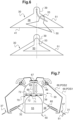
- the hook 50 comprises at least one reversible magnet called "normally closed magnet 63", and for example at least two normally closed magnets 63 equally distributed in azimuth with regard to the elevation direction DIR according to the Figure 5 .
- the catcher 50 may comprise at least one reversible magnet called "normally open magnet 64" and for example at least two normally open magnets 64 equally distributed in azimuth with regard to the elevation direction DIR according to the Figure 5 .
- Each normally open magnet 64 is magnetizable in the magnetization zone except in the event of an electrical failure of the hook and the aircraft to be carried according to this embodiment.
- each normally open magnet 64 is in communication with a positioning computer 16 and/or can be electrically connected to a source of electrical energy.
- the electrical source 15 of the aircraft to be carried represents the source of electrical energy magnetizing the reversible magnets 62.
- the positioning computer 16 can then transmit to the normally open magnets 64 a signal modifying the orientation of the magnetic field emitted by each normally open magnet 64.
- Each normally closed magnet 63 is connected to an electrically independent module 83 to be magnetizable in the event of detection of a said electrical failure, no normally open magnet 64 not cooperating with said module
- the recovery system 20 can include at least one switch 65 between said source of electrical energy 15 and each normally open magnet 64.
- a switch 65 can also be interposed for example between the module 83 and each normally closed magnet 63.
- Each switch 65 can be controlled by a remote human pilot or by an automatic system, for example depending on the position of the aircraft to be carried 10 relative to the carrier aircraft 1.
- the fixing device 60 may comprise an at least partially mechanical subassembly.
- the fixing device 60 can include at least one locking finger 66 movable relative to the guide section 31.
- at least one locking finger 66 movable relative to the guide section 31.
- four blocking fingers 66 are carried by the receiver 30 and equally distributed in azimuth around the elevation direction DIR.
- each locking finger 66 can be articulated to a support 86 of the receiver 30 by a connection pivot.
- Such support 86 can be integral with the centering portion 39 or even with the guide section 31 for example.
- the support 86 can take the form of an arm.
- Each locking finger 66 can thus rotate between a free position POS1 illustrated in dotted lines and a locking position POS2. In the free position POS1, no blocking finger 66 blocks the hook 50.
- the hook 50 is maintained according to the realization of the Figure 7 between each blocking finger 66 and an internal face 32 of the receiver 30.
- the receiver 30 can comprise an orifice 37 per blocking finger 66, each blocking finger 66 passing through a such orifice 37 to penetrate into the internal volume 38 in which the hook 50 is housed.
- Each locking finger 66 can be controlled by a motor for example. However, according to the example of the Figure 7 , each blocking finger 66 is mechanically controlled by the hook 50.
- each locking finger 66 is connected to a piston 67, a pallet of the locking finger 66 resting on the piston 67 for example.
- This piston 67 is integral with a rod 68 fixed to a plate 69 present in the internal volume, and for example in the centering portion 39. Therefore, when the hook 50 sinks into the receiver 30, the hook 50 and according to the example the centering finger 53 pushes the plate 69. This results in a translation of the piston 67 which induces the rotation of each blocking finger 66 towards its blocking position POS2. The locking fingers 66 then block the hook by bracing.
- the reversible magnets 62 can be inhibited.
- the aircraft to be carried 10 can be set in motion in order to be slightly pushed towards the high, namely towards the piston 67 to “un-button” and release the locking fingers 66.
- An actuator can also act on the locking fingers 66 for this purpose.
- a blocking finger 66 can take the form of a hook movable in rotation and actuated by a motor 88.
- the hook In the blocking position POS2, the hook can be inserted in a groove 87 and in particular under a stop of the hook 50 and in particular the centering finger 53 according to the example illustrated.
- the annular centering portion illustrated on the Figure 9 can be replaced by a bell.
- the recovery system 20 may include at least one positioning device 70 to help pilot the drone or even to possibly control a fixing device 60.
- a positioning device 70 generates a signal which varies as a function of a relative position of the catcher 50 relative to the receiver 30.
- a signal can be a digital, analog, video signal, etc.
- the positioning device 70 comprises an optical system provided with a camera 71 carried by the receiver 30.
- the positioning device 70 comprises an optical system provided with a camera 71 carried by the hook 50.
- the camera is possibly carried by the connection section 51 or the centering finger 53.
- the camera is positioned at the top of the centering finger 53.
- the optical system may include at least one target 72 carried by the receiver 30.
- three circle type targets 72 are arranged on the receiver 30.
- the geometric symbols are for example located on the centering portion 39. In the presence of a fixing device 60 according to the Figure 7 , the symbols can be arranged on plate 69.
- the optical system includes a positioning computer 16 which generates a signal according to the shape of the targets 72 visualized by the camera 71.
- the positioning computer 16 implements a usual image processing algorithm.
- the positioning calculator 16 may include for example at least one processor and at least one memory, at least one integrated circuit, at least one programmable system, at least one logic circuit, these examples not limiting the scope given to the expression “ calculator”.
- the term processor can designate as well a central processing unit known by the acronym CPU, a graphics processing unit GPU, a digital unit known by the acronym DSP, a microcontroller, etc.
- the positioning calculator 16 can be located in the aircraft to carry 10 for example.
- the positioning computer 16 can be an independent computer and/or be part of a calculation unit integrating at least one other computer and for example an automatic pilot computer 13.
- the positioning device 70 may comprise at least one proximity sensor 73.
- a proximity sensor may comprise a hall effect sensor, a push button or even a usual ultrasonic positioning system 74.
- an ultrasonic positioning system 74 may comprise ultrasonic transmitters 742 arranged on the receiver 30, and for example at the end of the conical guide section according to the Figure 10 , and ultrasound sensors 741 arranged on the hook according to the Figure 10 or on the aircraft to wear which cooperate with a drone positioning calculator.
- Such an ultrasonic positioning system 74 can make it possible to precisely direct the drone towards the receiver 30 a few tens of meters away.
- the positioning device 70 is connected to at least one switch 65 controlling at least one reversible magnet.
- FIG. 12 illustrates an exemplary embodiment of a drone according to the invention.
- an ultrasonic and or radio positioning system 74 and a camera 71 communicate with a positioning computer 16.
- This positioning computer 16 processes the data obtained to determine the position of the catcher 50 relative to the receiver 30 by example of a Kalman filter.
- the positioning computer 16 is connected to each switch 65 to transmit an order to it in order to magnetize the hook 50 to the receiver 30 when the hook 50 is in an envelope of predetermined positions.
- a position sensor can also be connected to each switch 65 without going through the positioning computer 16.
- This architecture then has two dissimilar means for controlling each switch 65, which optimizes safety.
- each switch 65 can also be in communication with a remote control 85 operable by a human operator.
- a first switch 651 makes it possible to inhibit the normally open magnets 64 on request by being arranged between the positioning computer 16 and these normally open magnets 64.
- a second switch 652 makes it possible to inhibit the normally closed magnets 63 on request by being arranged between the module 83 and these normally closed magnets 63.
- the positioning computer 16 can also communicate with an automatic pilot computer 13 which controls motors 14 or other types of control means to move the aircraft to be carried 10 in the atmosphere.
- each normally open magnet 64 is then controlled by the control computer 16.
- the control computer can send a signal to each normally open magnet 64 to change the orientation of its magnetic field or create a magnetic field.
- each normally closed magnet 63 is connected to a module 83.
- a module may include a calculator 831 or equivalent and an electrical source 832.
- the module 83 may include a usual analyzer 833 to detect whether the module 83 receives an electrical signal. If not, the module 83 transmits a signal to each normally closed magnet 63 to make it magnetizable.
- the positioning device 70 may comprise a satellite positioning system 500 integral with the aircraft to be carried and for example connected to the positioning computer 16 and/or to the automatic pilot computer 13.
- This positioning system by satellites 500 integral with the aircraft to be carried can cooperate with a satellite positioning system of the carrying aircraft and/or the receiver to precisely position the catcher relative to the receiver via a differential measurement between the satellite positioning system 500 integral with the aircraft to be carried and the satellite positioning system of the carrier aircraft and/or the receiver.
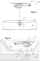
- THE figures 13 and 14 illustrate a procedure for recovering a carrier aircraft 10 of the drone type 10 with a carrier aircraft 1 of the helicopter type.
- the aircraft to be carried 10 can be authorized to fly in a restricted zone Z11.
- a restricted zone Z11 can have the shape of a cylinder with a height of 40 meters and a radius of 100 meters. The dimensions of a restricted area can be modified.
- the carrier aircraft 1 can be maneuvered to position the receiver 30 in this restricted zone Z11, for example at the top of this restricted zone Z11 and substantially on its axis of symmetry of revolution.
- the space surrounding or even present under the carrier aircraft can be divided into three zones Z1, Z2, Z3 including a secure zone Z1 in which the restricted zone Z11 is located, an intermediate zone Z2 and a danger zone Z3.
- the danger zone Z3 contains the carrier aircraft, the intermediate zone Z2 being arranged between the danger zone Z3 and the secure zone Z1.
- the aircraft to be carried 10 moves in the secure zone Z1 to reach the receiver 30.
- the aircraft to be carried can be equipped with a positioning system comprising in particular a satellite positioning system 500 and an ultrasound system 74. Therefore, the piloting computer can request the satellite positioning system 500 to direct the aircraft to be carried towards the receiver 30 as long as this satellite positioning system 500 is more precise than the ultrasonic system 74 or up to a certain distance from the receiver. Therefore, when the ultrasound system 74 becomes effective, the control is carried out in a second step using the data from the ultrasound system 74 then, if necessary, with the camera system 71 in a final phase.
- a positioning system comprising in particular a satellite positioning system 500 and an ultrasound system 74. Therefore, the piloting computer can request the satellite positioning system 500 to direct the aircraft to be carried towards the receiver 30 as long as this satellite positioning system 500 is more precise than the ultrasonic system 74 or up to a certain distance from the receiver. Therefore, when the ultrasound system 74 becomes effective, the control is carried out in a second step using the data from the ultrasound system 74 then, if necessary, with the camera system 71 in a
- the aircraft to be carried 1 evolves in the intermediate zone Z2 for example following a gust of wind
- automatic orders developed by one or more memorized laws of the piloting computer and/or given by an operator are generated and transmitted to the control organs.
- a new waypoint located on the ground is generated to force the drone to return to the secure zone Z1.
- an order may take the form of a signal ordering the drone's engines to be cut off.
- a signal can be transmitted to a parachute system to deploy at least one parachute, this parachute can for example be controlled according to the teaching of the request for patent FR 3074144 .
- a receiver comprising only a magnetization zone and not blocking fingers or only at least one blocking finger.
- a magnetization zone on the catcher and reversible magnets on the receiver.
- the catcher and the receiver each have a magnetization zone and reversible magnets.
Landscapes
- Engineering & Computer Science (AREA)
- Aviation & Aerospace Engineering (AREA)
- Remote Sensing (AREA)
- Mechanical Engineering (AREA)
- Chemical & Material Sciences (AREA)
- Combustion & Propulsion (AREA)
- Microelectronics & Electronic Packaging (AREA)
- Transportation (AREA)
- Position Fixing By Use Of Radio Waves (AREA)
- Load-Engaging Elements For Cranes (AREA)
- Traffic Control Systems (AREA)
Claims (14)
- Bergungssystem (20), um zumindest im Flug ein zu tragendes Luftfahrzeug (10) von einem Trägerluftfahrzeug (1) aus zu bergen, wobei das Bergungssystem (20) einen Aufnehmer (30), der geeignet ist, von dem Trägerluftfahrzeug (1) getragen zu werden, und einen Aufhänger (50) umfasst, der geeignet ist, von dem zu tragenden Luftfahrzeug (10) getragen zu werden, wobei der Aufnehmer (30) ein Innenvolumen (38) aufweist, das über eine Durchgangsfläche (41) in ein Außenmedium (EXT) mündet, der Aufnehmer (30) einen hohlen Führungsabschnitt (31) aufweist, wobei der Führungsabschnitt (31) aufgeweitet ist, der Aufhänger (50) einen aufgeweiteten Verbindungsabschnitt (51) aufweist, der geeignet ist, zumindest teilweise in dem Innenvolumen (38) enthalten zu sein, wobei das Bergungssystem (20) eine Befestigungsvorrichtung (60) umfasst, die den Aufhänger (50) reversibel am Aufnehmer (30) befestigt,
dadurch gekennzeichnet, dass der Aufhänger (50) fest mit einem Mast (55) verbunden ist, der konfiguriert ist, um an dem zu tragenden Luftfahrzeug (10) befestigt zu werden, wobei der Mast (55) ein Segment (56) umfasst, das außerhalb des Aufnehmers (30) angeordnet ist, wenn der Aufhänger (50) an den Aufnehmer (30) angedockt ist, wobei der Führungsabschnitt (31) asymmetrisch ist. - System nach Anspruch 1,
dadurch gekennzeichnet, dass der Aufnehmer (30) mindestens eine Öffnung (37) aufweist, die eine Wand (42) dieses Aufnehmers (30) von einer Seite zur anderen durchquert, wobei die mindestens eine Öffnung (37) das Außenmedium (EXT) und das Innenvolumen (38) in Fluidverbindung bringt. - System nach einem der Ansprüche 1 bis 2,
dadurch gekennzeichnet, dass der Aufnehmer (30) einen Zentrierabschnitt (39) umfasst, der fest mit einer Aufnahmespitze (34) des Führungsabschnitts (31) verbunden ist, wobei der Aufhänger (50) einen Zentrierfinger (53) umfasst, und der Zentrierfinger (53) konfiguriert ist, um in den Zentrierabschnitt (39) einzudringen. - System nach einem der Ansprüche 1 bis 3,
dadurch gekennzeichnet, dass mindestens der Aufhänger (50) oder der Aufnehmer (30) mindestens ein Pufferelement (80) aufweist, das konfiguriert ist, um die Folgen eines Kontakts zwischen dem Aufhänger (50) und dem Aufnehmer (30) zu begrenzen. - System nach einem der Ansprüche 1 bis 4,
dadurch gekennzeichnet, dass die Befestigungsvorrichtung (60) mindestens eine Magnetisierungszone (61) aufweist, die fest mit dem Aufhänger (50) oder dem Aufnehmer (30) verbunden ist, wobei die Befestigungsvorrichtung (60) mindestens einen reversiblen Magneten (62) aufweist, der fest mit dem Aufhänger (50) oder dem Aufnehmer (30) verbunden ist, von der Magnetisierungszone frei ist und geeignet ist, auf Befehl an der mindestens einen Magnetisierungszone (61) magnetisiert oder entmagnetisiert zu werden. - System nach Anspruch 5,
dadurch gekennzeichnet, dass der mindestens eine reversible Magnet (62) mindestens einen normalerweise offenen Magneten (64) umfasst, der außer im Falle einer elektrischen Störung an der Magnetisierungszone magnetisierbar ist, wobei der mindestens eine reversible Magnet (62) mindestens einen normalerweise geschlossenen Magneten (63) umfasst, der im Falle der Erfassung einer besagten elektrischen Störung durch ein elektrisch autonomes Modul an der Magnetisierungszone magnetisierbar ist, wobei der mindestens eine normalerweise offene Magnet (64) nicht mit dem Modul zusammenwirkt. - System nach Anspruch 6,
dadurch gekennzeichnet, dass das Bergungssystem (20) mindestens einen Schalter (65) aufweist, um mindestens den mindestens einen normalerweise geschlossenen Magneten (63) oder den mindestens einen normalerweise offenen Magneten (64) zu hemmen. - System nach einem der Ansprüche 1 bis 7,
dadurch gekennzeichnet, dass das Bergungssystem (20) mindestens eine Positionierungsvorrichtung (70) umfasst, die ein Signal erzeugt, das sich in Abhängigkeit von einer relativen Position des Aufhängers (50) in Bezug auf den Aufnehmer (30) ändert. - System nach Anspruch 8,
dadurch gekennzeichnet, dass die Positionierungsvorrichtung (70) eine von dem Aufhänger (50) getragene Kamera (71) sowie einen mit der Kamera (71) und mindestens einem von dem Aufnehmer (30) getragenen Ziel (72) verbundenen Positionierungsrechner (16) umfasst. - System nach einem der Ansprüche 8 bis 9,
dadurch gekennzeichnet, dass die Positionierungsvorrichtung (70) einen Näherungssensor (73, 74) umfasst. - System nach einem der Ansprüche 8 bis 10 und nach Anspruch 8,
dadurch gekennzeichnet, dass die Positionierungsvorrichtung (70) mit dem Schalter (65) verbunden ist. - System nach einem der Ansprüche 1 bis 11, dadurch gekennzeichnet, dass die Befestigungsvorrichtung (60) mindestens einen Sperrfinger (66) aufweist, der in Bezug auf den Führungsabschnitt (31) beweglich ist, wobei der Sperrfinger (66) zwischen einer freien Position (POS1), in der der Sperrfinger (66) den Aufhänger (50) nicht behindert, und einer Sperrposition (POS2) beweglich ist, in der der Aufhänger (50) zumindest durch den Sperrfinger (66) gehalten ist.
- System nach Anspruch 12,
dadurch gekennzeichnet, dass der Sperrfinger (66) mechanisch durch den Aufhänger (50) zumindest von der freien Position (POS1) in die Sperrposition (POS2) gesteuert wird, wobei der Sperrfinger (66) mit einem translatorisch beweglichen Kolben (67) verbunden ist, so dass eine durch den Aufhänger (50) induzierte Translation des Kolbens (67) eine Rotation des Sperrfingers (66) bewirkt. - Baugruppe (100) mit einem Trägerluftfahrzeug (1) und einem zu tragenden Luftfahrzeug (10),
dadurch gekennzeichnet, dass die Anordnung (100) ein Bergungssystem (20) nach einem der Ansprüche 1 bis 13 umfasst, wobei der Aufnehmer (30) an dem Trägerflugzeug (1) und der Aufhänger (50) an dem zu tragenden Luftfahrzeug (10) eingehängt ist.
Applications Claiming Priority (1)
| Application Number | Priority Date | Filing Date | Title |
|---|---|---|---|
| FR1911767A FR3102147B1 (fr) | 2019-10-21 | 2019-10-21 | Système de récupération d’un aéronef à porter |
Publications (2)
| Publication Number | Publication Date |
|---|---|
| EP3812271A1 EP3812271A1 (de) | 2021-04-28 |
| EP3812271B1 true EP3812271B1 (de) | 2023-09-27 |
Family
ID=69468780
Family Applications (1)
| Application Number | Title | Priority Date | Filing Date |
|---|---|---|---|
| EP20186917.9A Active EP3812271B1 (de) | 2019-10-21 | 2020-07-21 | System zur wiederherstellung eines zu tragenden luftfahrzeugs |
Country Status (2)
| Country | Link |
|---|---|
| EP (1) | EP3812271B1 (de) |
| FR (1) | FR3102147B1 (de) |
Families Citing this family (2)
| Publication number | Priority date | Publication date | Assignee | Title |
|---|---|---|---|---|
| CN110606217A (zh) * | 2019-10-14 | 2019-12-24 | 中国航空工业集团公司沈阳飞机设计研究所 | 一种无人机海面迫降回收系统 |
| CN116331771B (zh) * | 2023-03-23 | 2025-08-22 | 亿航智能设备(广州)有限公司 | 一种物资抛投动态调控方法、设备及计算机可读存储介质 |
Family Cites Families (13)
| Publication number | Priority date | Publication date | Assignee | Title |
|---|---|---|---|---|
| US3249322A (en) * | 1964-04-06 | 1966-05-03 | Jr Raymond Prunty Holland | Air train |
| US3389880A (en) | 1966-06-21 | 1968-06-25 | Recovery Res Systems Inc | Parachute system for mid-air load recovery |
| DE3206299A1 (de) | 1981-02-24 | 1982-09-09 | British Aerospace Public Ltd. Co., London | Vorrichtung zum auffangen und zurueckhalten eines flugkoerpers |
| US4753400A (en) | 1987-02-13 | 1988-06-28 | Pioneer Systems, Incorporated | Shipboard air vehicle retrieval apparatus |
| JP4300010B2 (ja) | 2002-10-08 | 2009-07-22 | 富士重工業株式会社 | 無人ヘリコプタ、無人ヘリコプタの離陸方法及び無人ヘリコプタの着陸方法 |
| US7410125B2 (en) | 2005-05-05 | 2008-08-12 | Lockheed Martin Corporation | Robotically assisted launch/capture platform for an unmanned air vehicle |
| JP5309037B2 (ja) | 2007-01-18 | 2013-10-09 | アールトン,ポール,イー. | 回転翼航空機 |
| US8162256B2 (en) | 2008-03-19 | 2012-04-24 | Honeywell International Inc. | Launch and capture systems for vertical take-off and landing (VTOL) vehicles |
| FR2941922B1 (fr) | 2009-02-12 | 2012-08-17 | Geocean | Systeme de lancement et de reception d'un aerodyne captif |
| FR2974786B1 (fr) | 2011-05-03 | 2013-11-22 | Eurocopter France | Dispositif de largage et de recuperation d'un drone, et aeronef associe |
| US9448562B1 (en) * | 2015-08-18 | 2016-09-20 | Skycatch, Inc. | Utilizing acceleration information for precision landing of unmanned aerial vehicles |
| FR3074144B1 (fr) | 2017-11-30 | 2021-11-26 | Airbus Helicopters | Drone muni d'au mons un parachute |
| CN108945531B (zh) * | 2018-09-20 | 2023-08-01 | 哈尔滨理工大学 | 小型在轨卫星捕获对接机构 |
-
2019
- 2019-10-21 FR FR1911767A patent/FR3102147B1/fr not_active Expired - Fee Related
-
2020
- 2020-07-21 EP EP20186917.9A patent/EP3812271B1/de active Active
Non-Patent Citations (1)
| Title |
|---|
| ANONYMOUS: "Soyuz 7K-OK variant", 27 December 2017 (2017-12-27), From: http://www.russianspaceweb.com/soyuz-7k-ok.html, XP055918520, Retrieved from the Internet <URL:https://web.archive.org/web/20171227181411/http://www.russianspaceweb.com/images/spacecraft/manned/soyuz/7k_ok/design/7k-ok_info_silo_1.jpg> [retrieved on 20220505] * |
Also Published As
| Publication number | Publication date |
|---|---|
| FR3102147A1 (fr) | 2021-04-23 |
| EP3812271A1 (de) | 2021-04-28 |
| FR3102147B1 (fr) | 2022-05-06 |
Similar Documents
| Publication | Publication Date | Title |
|---|---|---|
| EP3712059B1 (de) | Verfahren und vorrichtung zum verschieben des schwerpunktes eines luftfahrzeugs | |
| EP3210658B1 (de) | Drohne, die mit hochklappbaren drohnenhalterungen ausgestattet ist | |
| EP3210660B1 (de) | Drohne mit zusammenklappbaren verbindungsarmen | |
| AU2019217244B2 (en) | Suspended load stability systems and methods | |
| US10370089B2 (en) | Weight-shifting coaxial helicopter | |
| EP3728029B1 (de) | System und verfahren zur automatischen nutzlastaufnahme durch ein unbemanntes luftfahrzeug | |
| KR101700754B1 (ko) | 비행체의 착륙 시스템 | |
| FR2974786A1 (fr) | Dispositif de largage et de recuperation d'un drone, et aeronef associe | |
| EP3282335A1 (de) | Integriertes kontroll-/steuermodul für flugdrohne | |
| EP3812271B1 (de) | System zur wiederherstellung eines zu tragenden luftfahrzeugs | |
| EP2407377A1 (de) | Verfahren und Luftfahrzeug, das mit einem Heck-Kipprotor ausgestattet ist | |
| FR3046988A1 (fr) | Systeme d'ejection de parachute pour aeronef | |
| FR3037316A1 (fr) | Dispositif volant sans pilote aero-largable | |
| US12565303B2 (en) | UAV having lower cargo bay door(s) | |
| EP2799331B1 (de) | System und Methode zur Steuerung eines Mittels zur Nickstabilisierung eines Fluggerätes. | |
| WO2007096539A1 (fr) | Engin spatial et procede pour faire fonctionner l'engin spatial | |
| CA3020283C (fr) | Drone muni d'au moins un parachute | |
| FR3040687A3 (fr) | Helicoptere a plusieurs rotors de pas variable | |
| FR2964946A1 (fr) | Petit engin volant sans pilote | |
| FR2675114A1 (fr) | Dispositif a engin volant pour le survol d'une zone, notamment en vue de sa surveillance. | |
| FR2685283A1 (fr) | Engin volant sans pilote et installation le mettant en óoeuvre. | |
| US12515794B2 (en) | UAV having a rotatable cargo bay | |
| KR102561768B1 (ko) | 열기구를 이용한 캐니스터 낙하 시스템 및 이의 동작 방법 | |
| EP1266825B1 (de) | Verfahren zum Trennen eines selbstangetriebenen Flugkörper von seinem Träger | |
| FR2652640A1 (fr) | Procede et systeme de guidage autonome vers une cible d'un projectile balistique aeroporte propulse. |
Legal Events
| Date | Code | Title | Description |
|---|---|---|---|
| PUAI | Public reference made under article 153(3) epc to a published international application that has entered the european phase |
Free format text: ORIGINAL CODE: 0009012 |
|
| STAA | Information on the status of an ep patent application or granted ep patent |
Free format text: STATUS: THE APPLICATION HAS BEEN PUBLISHED |
|
| AK | Designated contracting states |
Kind code of ref document: A1 Designated state(s): AL AT BE BG CH CY CZ DE DK EE ES FI FR GB GR HR HU IE IS IT LI LT LU LV MC MK MT NL NO PL PT RO RS SE SI SK SM TR |
|
| AX | Request for extension of the european patent |
Extension state: BA ME |
|
| STAA | Information on the status of an ep patent application or granted ep patent |
Free format text: STATUS: REQUEST FOR EXAMINATION WAS MADE |
|
| 17P | Request for examination filed |
Effective date: 20210630 |
|
| RBV | Designated contracting states (corrected) |
Designated state(s): AL AT BE BG CH CY CZ DE DK EE ES FI FR GB GR HR HU IE IS IT LI LT LU LV MC MK MT NL NO PL PT RO RS SE SI SK SM TR |
|
| STAA | Information on the status of an ep patent application or granted ep patent |
Free format text: STATUS: EXAMINATION IS IN PROGRESS |
|
| 17Q | First examination report despatched |
Effective date: 20220511 |
|
| REG | Reference to a national code |
Ref country code: DE Ref legal event code: R079 Free format text: PREVIOUS MAIN CLASS: B64D0001220000 Ipc: B64U0070200000 Ref document number: 602020018169 Country of ref document: DE |
|
| GRAP | Despatch of communication of intention to grant a patent |
Free format text: ORIGINAL CODE: EPIDOSNIGR1 |
|
| STAA | Information on the status of an ep patent application or granted ep patent |
Free format text: STATUS: GRANT OF PATENT IS INTENDED |
|
| RIC1 | Information provided on ipc code assigned before grant |
Ipc: B64U 10/13 20230101ALI20230508BHEP Ipc: B64D 1/12 20060101ALI20230508BHEP Ipc: B64D 5/00 20060101ALI20230508BHEP Ipc: B64D 1/22 20060101ALI20230508BHEP Ipc: B64U 70/20 20230101AFI20230508BHEP |
|
| INTG | Intention to grant announced |
Effective date: 20230607 |
|
| P01 | Opt-out of the competence of the unified patent court (upc) registered |
Effective date: 20230530 |
|
| GRAS | Grant fee paid |
Free format text: ORIGINAL CODE: EPIDOSNIGR3 |
|
| GRAA | (expected) grant |
Free format text: ORIGINAL CODE: 0009210 |
|
| STAA | Information on the status of an ep patent application or granted ep patent |
Free format text: STATUS: THE PATENT HAS BEEN GRANTED |
|
| AK | Designated contracting states |
Kind code of ref document: B1 Designated state(s): AL AT BE BG CH CY CZ DE DK EE ES FI FR GB GR HR HU IE IS IT LI LT LU LV MC MK MT NL NO PL PT RO RS SE SI SK SM TR |
|
| REG | Reference to a national code |
Ref country code: GB Ref legal event code: FG4D Free format text: NOT ENGLISH |
|
| REG | Reference to a national code |
Ref country code: CH Ref legal event code: EP |
|
| REG | Reference to a national code |
Ref country code: DE Ref legal event code: R096 Ref document number: 602020018169 Country of ref document: DE |
|
| REG | Reference to a national code |
Ref country code: IE Ref legal event code: FG4D Free format text: LANGUAGE OF EP DOCUMENT: FRENCH |
|
| REG | Reference to a national code |
Ref country code: LT Ref legal event code: MG9D |
|
| PG25 | Lapsed in a contracting state [announced via postgrant information from national office to epo] |
Ref country code: GR Free format text: LAPSE BECAUSE OF FAILURE TO SUBMIT A TRANSLATION OF THE DESCRIPTION OR TO PAY THE FEE WITHIN THE PRESCRIBED TIME-LIMIT Effective date: 20231228 |
|
| PG25 | Lapsed in a contracting state [announced via postgrant information from national office to epo] |
Ref country code: SE Free format text: LAPSE BECAUSE OF FAILURE TO SUBMIT A TRANSLATION OF THE DESCRIPTION OR TO PAY THE FEE WITHIN THE PRESCRIBED TIME-LIMIT Effective date: 20230927 Ref country code: RS Free format text: LAPSE BECAUSE OF FAILURE TO SUBMIT A TRANSLATION OF THE DESCRIPTION OR TO PAY THE FEE WITHIN THE PRESCRIBED TIME-LIMIT Effective date: 20230927 Ref country code: NO Free format text: LAPSE BECAUSE OF FAILURE TO SUBMIT A TRANSLATION OF THE DESCRIPTION OR TO PAY THE FEE WITHIN THE PRESCRIBED TIME-LIMIT Effective date: 20231227 Ref country code: LV Free format text: LAPSE BECAUSE OF FAILURE TO SUBMIT A TRANSLATION OF THE DESCRIPTION OR TO PAY THE FEE WITHIN THE PRESCRIBED TIME-LIMIT Effective date: 20230927 Ref country code: LT Free format text: LAPSE BECAUSE OF FAILURE TO SUBMIT A TRANSLATION OF THE DESCRIPTION OR TO PAY THE FEE WITHIN THE PRESCRIBED TIME-LIMIT Effective date: 20230927 Ref country code: HR Free format text: LAPSE BECAUSE OF FAILURE TO SUBMIT A TRANSLATION OF THE DESCRIPTION OR TO PAY THE FEE WITHIN THE PRESCRIBED TIME-LIMIT Effective date: 20230927 Ref country code: GR Free format text: LAPSE BECAUSE OF FAILURE TO SUBMIT A TRANSLATION OF THE DESCRIPTION OR TO PAY THE FEE WITHIN THE PRESCRIBED TIME-LIMIT Effective date: 20231228 Ref country code: FI Free format text: LAPSE BECAUSE OF FAILURE TO SUBMIT A TRANSLATION OF THE DESCRIPTION OR TO PAY THE FEE WITHIN THE PRESCRIBED TIME-LIMIT Effective date: 20230927 |
|
| REG | Reference to a national code |
Ref country code: NL Ref legal event code: MP Effective date: 20230927 |
|
| REG | Reference to a national code |
Ref country code: AT Ref legal event code: MK05 Ref document number: 1615201 Country of ref document: AT Kind code of ref document: T Effective date: 20230927 |
|
| PG25 | Lapsed in a contracting state [announced via postgrant information from national office to epo] |
Ref country code: NL Free format text: LAPSE BECAUSE OF FAILURE TO SUBMIT A TRANSLATION OF THE DESCRIPTION OR TO PAY THE FEE WITHIN THE PRESCRIBED TIME-LIMIT Effective date: 20230927 |
|
| PG25 | Lapsed in a contracting state [announced via postgrant information from national office to epo] |
Ref country code: IS Free format text: LAPSE BECAUSE OF FAILURE TO SUBMIT A TRANSLATION OF THE DESCRIPTION OR TO PAY THE FEE WITHIN THE PRESCRIBED TIME-LIMIT Effective date: 20240127 |
|
| PG25 | Lapsed in a contracting state [announced via postgrant information from national office to epo] |
Ref country code: AT Free format text: LAPSE BECAUSE OF FAILURE TO SUBMIT A TRANSLATION OF THE DESCRIPTION OR TO PAY THE FEE WITHIN THE PRESCRIBED TIME-LIMIT Effective date: 20230927 |
|
| PG25 | Lapsed in a contracting state [announced via postgrant information from national office to epo] |
Ref country code: ES Free format text: LAPSE BECAUSE OF FAILURE TO SUBMIT A TRANSLATION OF THE DESCRIPTION OR TO PAY THE FEE WITHIN THE PRESCRIBED TIME-LIMIT Effective date: 20230927 |
|
| PG25 | Lapsed in a contracting state [announced via postgrant information from national office to epo] |
Ref country code: SM Free format text: LAPSE BECAUSE OF FAILURE TO SUBMIT A TRANSLATION OF THE DESCRIPTION OR TO PAY THE FEE WITHIN THE PRESCRIBED TIME-LIMIT Effective date: 20230927 Ref country code: RO Free format text: LAPSE BECAUSE OF FAILURE TO SUBMIT A TRANSLATION OF THE DESCRIPTION OR TO PAY THE FEE WITHIN THE PRESCRIBED TIME-LIMIT Effective date: 20230927 Ref country code: IS Free format text: LAPSE BECAUSE OF FAILURE TO SUBMIT A TRANSLATION OF THE DESCRIPTION OR TO PAY THE FEE WITHIN THE PRESCRIBED TIME-LIMIT Effective date: 20240127 Ref country code: ES Free format text: LAPSE BECAUSE OF FAILURE TO SUBMIT A TRANSLATION OF THE DESCRIPTION OR TO PAY THE FEE WITHIN THE PRESCRIBED TIME-LIMIT Effective date: 20230927 Ref country code: EE Free format text: LAPSE BECAUSE OF FAILURE TO SUBMIT A TRANSLATION OF THE DESCRIPTION OR TO PAY THE FEE WITHIN THE PRESCRIBED TIME-LIMIT Effective date: 20230927 Ref country code: CZ Free format text: LAPSE BECAUSE OF FAILURE TO SUBMIT A TRANSLATION OF THE DESCRIPTION OR TO PAY THE FEE WITHIN THE PRESCRIBED TIME-LIMIT Effective date: 20230927 Ref country code: AT Free format text: LAPSE BECAUSE OF FAILURE TO SUBMIT A TRANSLATION OF THE DESCRIPTION OR TO PAY THE FEE WITHIN THE PRESCRIBED TIME-LIMIT Effective date: 20230927 Ref country code: SK Free format text: LAPSE BECAUSE OF FAILURE TO SUBMIT A TRANSLATION OF THE DESCRIPTION OR TO PAY THE FEE WITHIN THE PRESCRIBED TIME-LIMIT Effective date: 20230927 Ref country code: PT Free format text: LAPSE BECAUSE OF FAILURE TO SUBMIT A TRANSLATION OF THE DESCRIPTION OR TO PAY THE FEE WITHIN THE PRESCRIBED TIME-LIMIT Effective date: 20240129 |
|
| PG25 | Lapsed in a contracting state [announced via postgrant information from national office to epo] |
Ref country code: PL Free format text: LAPSE BECAUSE OF FAILURE TO SUBMIT A TRANSLATION OF THE DESCRIPTION OR TO PAY THE FEE WITHIN THE PRESCRIBED TIME-LIMIT Effective date: 20230927 |
|
| REG | Reference to a national code |
Ref country code: DE Ref legal event code: R097 Ref document number: 602020018169 Country of ref document: DE |
|
| PG25 | Lapsed in a contracting state [announced via postgrant information from national office to epo] |
Ref country code: DK Free format text: LAPSE BECAUSE OF FAILURE TO SUBMIT A TRANSLATION OF THE DESCRIPTION OR TO PAY THE FEE WITHIN THE PRESCRIBED TIME-LIMIT Effective date: 20230927 |
|
| PG25 | Lapsed in a contracting state [announced via postgrant information from national office to epo] |
Ref country code: DK Free format text: LAPSE BECAUSE OF FAILURE TO SUBMIT A TRANSLATION OF THE DESCRIPTION OR TO PAY THE FEE WITHIN THE PRESCRIBED TIME-LIMIT Effective date: 20230927 |
|
| PLBE | No opposition filed within time limit |
Free format text: ORIGINAL CODE: 0009261 |
|
| STAA | Information on the status of an ep patent application or granted ep patent |
Free format text: STATUS: NO OPPOSITION FILED WITHIN TIME LIMIT |
|
| 26N | No opposition filed |
Effective date: 20240628 |
|
| PG25 | Lapsed in a contracting state [announced via postgrant information from national office to epo] |
Ref country code: SI Free format text: LAPSE BECAUSE OF FAILURE TO SUBMIT A TRANSLATION OF THE DESCRIPTION OR TO PAY THE FEE WITHIN THE PRESCRIBED TIME-LIMIT Effective date: 20230927 |
|
| PG25 | Lapsed in a contracting state [announced via postgrant information from national office to epo] |
Ref country code: SI Free format text: LAPSE BECAUSE OF FAILURE TO SUBMIT A TRANSLATION OF THE DESCRIPTION OR TO PAY THE FEE WITHIN THE PRESCRIBED TIME-LIMIT Effective date: 20230927 |
|
| PG25 | Lapsed in a contracting state [announced via postgrant information from national office to epo] |
Ref country code: BG Free format text: LAPSE BECAUSE OF FAILURE TO SUBMIT A TRANSLATION OF THE DESCRIPTION OR TO PAY THE FEE WITHIN THE PRESCRIBED TIME-LIMIT Effective date: 20230927 |
|
| PG25 | Lapsed in a contracting state [announced via postgrant information from national office to epo] |
Ref country code: BG Free format text: LAPSE BECAUSE OF FAILURE TO SUBMIT A TRANSLATION OF THE DESCRIPTION OR TO PAY THE FEE WITHIN THE PRESCRIBED TIME-LIMIT Effective date: 20230927 |
|
| REG | Reference to a national code |
Ref country code: DE Ref legal event code: R119 Ref document number: 602020018169 Country of ref document: DE |
|
| PG25 | Lapsed in a contracting state [announced via postgrant information from national office to epo] |
Ref country code: MC Free format text: LAPSE BECAUSE OF FAILURE TO SUBMIT A TRANSLATION OF THE DESCRIPTION OR TO PAY THE FEE WITHIN THE PRESCRIBED TIME-LIMIT Effective date: 20230927 |
|
| REG | Reference to a national code |
Ref country code: CH Ref legal event code: PL |
|
| PG25 | Lapsed in a contracting state [announced via postgrant information from national office to epo] |
Ref country code: LU Free format text: LAPSE BECAUSE OF NON-PAYMENT OF DUE FEES Effective date: 20240721 |
|
| GBPC | Gb: european patent ceased through non-payment of renewal fee |
Effective date: 20240721 |
|
| PG25 | Lapsed in a contracting state [announced via postgrant information from national office to epo] |
Ref country code: LU Free format text: LAPSE BECAUSE OF NON-PAYMENT OF DUE FEES Effective date: 20240721 |
|
| PG25 | Lapsed in a contracting state [announced via postgrant information from national office to epo] |
Ref country code: DE Free format text: LAPSE BECAUSE OF NON-PAYMENT OF DUE FEES Effective date: 20250201 |
|
| PG25 | Lapsed in a contracting state [announced via postgrant information from national office to epo] |
Ref country code: BE Free format text: LAPSE BECAUSE OF NON-PAYMENT OF DUE FEES Effective date: 20240731 Ref country code: CH Free format text: LAPSE BECAUSE OF NON-PAYMENT OF DUE FEES Effective date: 20240731 |
|
| PG25 | Lapsed in a contracting state [announced via postgrant information from national office to epo] |
Ref country code: GB Free format text: LAPSE BECAUSE OF NON-PAYMENT OF DUE FEES Effective date: 20240721 |
|
| REG | Reference to a national code |
Ref country code: BE Ref legal event code: MM Effective date: 20240731 |
|
| PG25 | Lapsed in a contracting state [announced via postgrant information from national office to epo] |
Ref country code: IE Free format text: LAPSE BECAUSE OF NON-PAYMENT OF DUE FEES Effective date: 20240721 |
|
| PGFP | Annual fee paid to national office [announced via postgrant information from national office to epo] |
Ref country code: IT Payment date: 20250724 Year of fee payment: 6 |
|
| PGFP | Annual fee paid to national office [announced via postgrant information from national office to epo] |
Ref country code: FR Payment date: 20250725 Year of fee payment: 6 |
|
| PG25 | Lapsed in a contracting state [announced via postgrant information from national office to epo] |
Ref country code: CY Free format text: LAPSE BECAUSE OF FAILURE TO SUBMIT A TRANSLATION OF THE DESCRIPTION OR TO PAY THE FEE WITHIN THE PRESCRIBED TIME-LIMIT; INVALID AB INITIO Effective date: 20200721 |
|
| PG25 | Lapsed in a contracting state [announced via postgrant information from national office to epo] |
Ref country code: HU Free format text: LAPSE BECAUSE OF FAILURE TO SUBMIT A TRANSLATION OF THE DESCRIPTION OR TO PAY THE FEE WITHIN THE PRESCRIBED TIME-LIMIT; INVALID AB INITIO Effective date: 20200721 |