EP2407377A1 - Verfahren und Luftfahrzeug, das mit einem Heck-Kipprotor ausgestattet ist - Google Patents
Verfahren und Luftfahrzeug, das mit einem Heck-Kipprotor ausgestattet ist Download PDFInfo
- Publication number
- EP2407377A1 EP2407377A1 EP11005078A EP11005078A EP2407377A1 EP 2407377 A1 EP2407377 A1 EP 2407377A1 EP 11005078 A EP11005078 A EP 11005078A EP 11005078 A EP11005078 A EP 11005078A EP 2407377 A1 EP2407377 A1 EP 2407377A1
- Authority
- EP
- European Patent Office
- Prior art keywords
- aircraft
- mode
- operating mode
- propulsive
- torque
- Prior art date
- Legal status (The legal status is an assumption and is not a legal conclusion. Google has not performed a legal analysis and makes no representation as to the accuracy of the status listed.)
- Granted
Links
Images

Classifications
-
- B—PERFORMING OPERATIONS; TRANSPORTING
- B64—AIRCRAFT; AVIATION; COSMONAUTICS
- B64C—AEROPLANES; HELICOPTERS
- B64C27/00—Rotorcraft; Rotors peculiar thereto
- B64C27/82—Rotorcraft; Rotors peculiar thereto characterised by the provision of an auxiliary rotor or fluid-jet device for counter-balancing lifting rotor torque or changing direction of rotorcraft
- B64C2027/8218—Rotorcraft; Rotors peculiar thereto characterised by the provision of an auxiliary rotor or fluid-jet device for counter-balancing lifting rotor torque or changing direction of rotorcraft wherein the rotor or the jet axis is inclined with respect to the longitudinal horizontal or vertical plane of the helicopter
-
- B—PERFORMING OPERATIONS; TRANSPORTING
- B64—AIRCRAFT; AVIATION; COSMONAUTICS
- B64C—AEROPLANES; HELICOPTERS
- B64C27/00—Rotorcraft; Rotors peculiar thereto
- B64C27/82—Rotorcraft; Rotors peculiar thereto characterised by the provision of an auxiliary rotor or fluid-jet device for counter-balancing lifting rotor torque or changing direction of rotorcraft
- B64C2027/8236—Rotorcraft; Rotors peculiar thereto characterised by the provision of an auxiliary rotor or fluid-jet device for counter-balancing lifting rotor torque or changing direction of rotorcraft including pusher propellers
-
- B—PERFORMING OPERATIONS; TRANSPORTING
- B64—AIRCRAFT; AVIATION; COSMONAUTICS
- B64C—AEROPLANES; HELICOPTERS
- B64C27/00—Rotorcraft; Rotors peculiar thereto
- B64C27/82—Rotorcraft; Rotors peculiar thereto characterised by the provision of an auxiliary rotor or fluid-jet device for counter-balancing lifting rotor torque or changing direction of rotorcraft
- B64C2027/8263—Rotorcraft; Rotors peculiar thereto characterised by the provision of an auxiliary rotor or fluid-jet device for counter-balancing lifting rotor torque or changing direction of rotorcraft comprising in addition rudders, tails, fins, or the like
- B64C2027/8272—Rotorcraft; Rotors peculiar thereto characterised by the provision of an auxiliary rotor or fluid-jet device for counter-balancing lifting rotor torque or changing direction of rotorcraft comprising in addition rudders, tails, fins, or the like comprising fins, or movable rudders
Definitions
- the present invention relates to a method of piloting a rotary wing aircraft provided with a rear rotor adapted to pivot about a tilting axis, as well as such an aircraft.
- the invention relates to aircraft provided on the one hand with a rotary wing to at least partially ensure the lift of the aircraft and, on the other hand, with a rear rotor capable of countering the torque generated by the rotary wing on the airframe of the aircraft, this rear rotor being pivotable about an axis to contribute to the propulsion of the aircraft.
- the performance of a helicopter is typically limited by the rotational speed of the main rotor constituting the rotary wing.
- the relative speed of the blades of this main rotor relative to the surrounding air must especially be locally lower than the speed of sound.
- the life of the components is reduced especially due to the appearance of vibrations.
- the document FR 1511006 suggests the use of a caudal propellant propeller associated with the conventional rear anti-torque rotor of a helicopter.
- the caudal propeller then allows to discharge the main rotor of at least a portion of its propulsive function.
- the document FR1017976 suggests using an aircraft equipped with a rotary wing and a rear rotor capable of pivoting about a tilting axis.
- the rear rotor is used to counter the torque generated by the rotary wing and for the yaw control.
- the rear rotor tilts to participate in the propulsion of the aircraft, the yaw control being obtained by orienting the rear rotor on either side of a neutral position.
- Such an aircraft is sometimes referred to as a "vector-driven helicopter".
- the document US 3155341 presents a convertiplane equipped with a main rotor, a tilting rear rotor and a wing adapted to pass from a helicopter mode to an airplane mode.
- the document FR1536412 presents a pivot control mechanism of a rear rotor of a convertiplane.
- This mechanism comprises a single output relating to the pitch control and two inputs for the yaw control in helicopter mode and the thrust control in airplane mode, the transition from one command to the other operating gradually.
- the yaw control becomes inoperative while in helicopter mode the thrust control is inoperative.
- the object of the present invention is therefore to propose a method for piloting a tilting rear rotor aircraft and such an aircraft, said aircraft having a high forward speed.
- an orthonormal marker provided with a longitudinal axis, a transverse axis and an elevation axis is linked to the aircraft.
- the elevation axis and the longitudinal axis together define the first anteroposterior plane of symmetry.
- the axis of rotation is contained in a plane perpendicular to the first plane and substantially parallel to a second plane defined by the transverse axis and the longitudinal axis.
- the tail rotor is controlled solely by the first control means. Indeed, the rear rotor is then in a fixed position to counter the torque generated by the rotary wing on the aircraft cell.
- the tail rotor can switch from the anti-torque mode of operation during which the aircraft operates as a conventional helicopter to a propulsive mode of operation during which the aircraft operates as a vector-driven aircraft.
- a second control means drives the second step, the first control means controlling the inclination of the rear rotor relative to the anteroposterior plane by controlling the value of the first salient angle.
- the first projecting angle to direct the mass of air passing through the rear rotor towards the rear of the aircraft.
- the tail rotor participates alone or in combination with the rotary wing to the propulsion of the aircraft.
- the pilot controls the yaw of the aircraft.
- This method makes it possible to easily control a rotary wing aircraft provided with a tilting rear rotor so as to obtain a rotary wing aircraft capable of attaining substantial forward speeds without significant degradation over time of the components constituting the transmission chain of the aircraft. couple of the rotary wing.
- the method may comprise one or more of the following features.
- the tilt mode is changed to the propulsive operating mode when the first projecting angle becomes less than a predetermined threshold and switch from the propulsive operating mode to the anti-torque operating mode when the first projecting angle becomes greater than the predetermined threshold.
- the first projecting angle has a positive value when the tail rotor is in the required fixed position during the anti-torque operating mode, this first projecting angle having a zero value when the axis of rotation is contained. in the foreground, the first salient angle having a negative value when the rear rotor is in a position symmetrical to said first position with respect to said first plane.
- a minimum period of security can be provided before changing the operating mode.
- the second control means can be deactivated during the anti-torque operation mode.
- the first step can be progressively reduced.
- the rear rotor gradually participating in the propulsion, it becomes possible to unload the rotary wing by reducing the pitch of the first blades to reduce the lift of this rotary wing, and in fact to reduce the power consumed by the rotary wing.
- the first angle angle is automatically decreased to an angle given lower than the predetermined threshold for which the yaw movement of the aircraft is zero, in order to bring the rotation axis of the second blades in the foreground to counter the residual torque of the rotary wing.
- the tilting order therefore causes the rear rotor to pivot automatically until the first projecting angle reaches said given angle generating a zero yaw motion of the aircraft.
- the rear rotor is allowed to pivot from an anti-torque mode of operation to a propulsive mode of operation if the speed of advance of the aircraft is greater than a minimum transition speed.
- the minimum transition speed is determined for example by tests insofar as it depends on the mass of the aircraft, and its aerodynamic drag in particular. This minimum transition speed therefore differs from one aircraft to another. In addition, safety margins can be taken with respect to a theoretical minimum transition speed.
- Switching from one mode of operation to another is therefore allowed if predetermined aerological conditions are met.
- This bearing surface may be a flap arranged on a drift in elevation, the bearing surface being for example controlled to be substantially in the air flow sucked by the rear rotor during the propulsive operation mode.
- the addition of a correctly calibrated elevation drift provides a heading.
- the elevation drift minimizes the sensitivity of the aircraft to disturbances, including lateral aerodynamic disturbances.
- the movable bearing surface of this drift additionally provides the aircraft with a reaction capacity in the face of the disturbances encountered.
- the aircraft may have one or more of the following additional features.
- the switching device includes a transition button to require switching from one operating mode to another.
- the aircraft optionally comprises an angular sensor for measuring the first projecting angle.
- this aircraft can comprise indifferently at least one movable elevation bearing surface having a second variable salient angle with the first plane.
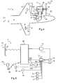
- the direction X represents the longitudinal axis of the aircraft schematically while another direction Y represents the transverse axis of this aircraft.
- a third direction Z is elevation and corresponds to the elevation axis of the aircraft.
- the figure 1 presents an aircraft 1 provided with a cell 4 extending longitudinally along a first plane P1 anteroposterior symmetry in elevation from a front end 4 'to a rear end 4. "It is noted that the first plane P1 is defined by the longitudinal axis X and the axis in elevation Z.
- the cell 4 carries a rotary wing 2 provided with a main rotor comprising a plurality of first blades 3.
- the aircraft then has modification members of the first pitch of the first blades 3, such as a set of cyclic plates controlled by a cyclic stick adapted to vary cyclically the first pitch of the first blades 3 and a collective pitch lever able to vary collectively the first pitch of all the first blades 3.
- the rear end 4 "of the cell 4 carries a rear rotor 10 provided with a plurality of second blades 12 rotating about an axis of rotation AX, the second pitch of the second blades 12 being modifiable.
- the rear rotor 10 can furthermore rotate about a tilting axis 11 to switch from a anti-torque operation during which the aircraft behaves like a conventional helicopter, to a propulsive mode of operation during which the aircraft is comparable to a vector-driven aircraft. Therefore, during the anti-torque operation mode the tail rotor is held firmly in a given position, while during the propulsion mode of operation the tail rotor 10 can rotate about the tilt axis.
- the axis of rotation AX can therefore rotate about the tilting axis 11 while moving in a second plane P2, for example orthogonal to the first plane P1 and parallel to a plane defined by the longitudinal axis X and the transverse axis Y of the aircraft.
- this axis of rotation AX is fixed, for example being orthogonal to the first plane P1 to counteract the torque generated by the rotary wing 2 on the cell 4.
- the axis of rotation AX then has a first salient angle ⁇ separating the axis of rotation AX from the first plane P1, this first projecting angle ⁇ possibly being a right angle during the anticouple operating mode. More precisely, the first projecting angle ⁇ separates the axis of rotation AX from the intersection of the first and second planes P1, P2.
- the axis of rotation AX can rotate around the tilting axis 11 in order to direct the air mass passing through the rear rotor 10 towards the rear of the aircraft.
- the rear rotor 10 pivots on both sides of the first plane P1 to participate in the propulsion of the aircraft and to control the yaw movement of this aircraft.
- the first protruding angle ⁇ varies in a range of 180 ° from the position of the rear rotor 10 represented in solid lines on the figure 1 towards the position of the rear rotor 10 shown in dashed lines on this figure 1 .
- the pilot uses a first control means 31, such as a lifter, and a second control means 32, a three-state push button and / or an analog rotary knob for example.
- a first control means 31 such as a lifter
- a second control means 32 a three-state push button and / or an analog rotary knob for example.
- the first control means 31 is used more precisely to modify the second pitch of the second blades 12 of the rear rotor 10.
- the pilot controls the yaw of the 1 by controlling the amplitude of the thrust generated by the rear rotor 10.
- the second control means 32 is deactivated for safety.
- the first control means 31 is used to orient the rear rotor 10 relative to the first plane P1 by controlling the value of the first projecting angle ⁇ , and the second control means 32 to modify the second step of the second blades 12. Therefore, the pilot always controls the yaw of the aircraft using the first control means 31, but controls the speed of advancement of the aircraft using the second means of control. command 32 in particular.
- the aircraft can have at least one supporting surface 6 in moving elevation, such as a flap arranged on a vertical drift.
- this bearing surface 6 may be controlled by the first control means 31 for example to be arranged in the air flow sucked by the rear rotor 10.
- a logic control means may also control this bearing surface 6 according to gyroscopic information to combat a temporary inclination in yaw of the aircraft, caused for example by an aerological disturbance.
- the aircraft comprises a switching means 40.
- the pilot uses this switching means 40 to change the operating mode.
- an automatic control system can also operate this switching means 40.
- a pivot means not shown on the figure 1 automatically rotates the rear rotor 10 during a transition phase.
- rotation of the rear rotor 10 is allowed only if the forward speed of the aircraft is greater than a predetermined minimum transition speed.
- the anti-torque mode of operation is changed to the propulsive operation mode.
- the action of the first and second control means 31, 32 then varies.
- the second step can be progressively increased. to maintain the aircraft at a forward speed greater than or equal to a given forward speed.
- the speed of advance given is equal to the speed of advance of the aircraft when the change of mode is required.
- the pilot requires the tilting of the tail rotor using the switching device.
- the rear rotor 10 then pivots about the tilting axis 11 to end up in the fixed position shown on the figure 1 .
- the first control means makes it possible to control the second step, the second control means becoming inoperative.
- a delay can be set up to ensure that the increase of the first salient angle ⁇ beyond the predetermined threshold ⁇ is not caused by aerological disturbances.
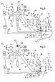
- the figure 4 has a section of a rear rotor 10 of an aircraft 1 according to the invention.
- the rear rotor 10 is arranged on the rear end 4 "of the cell 4 of the aircraft 1.
- the aircraft 1 comprises a rear gearbox 20 of power set in motion by a power plant not shown, the rear transmission gearbox rotating the second blades 12 about an axis of rotation AX.
- This rear transmission box 20 is provided with a fixed part 21 secured to the cell 4 by a link 21 "and set in motion by the power plant.
- the rear gearbox 20 is provided with a movable part. 22 carrying and driving the rear rotor 10, the movable part 22 cooperating with the fixed part 21.
- the aircraft 1 comprises a pivoting means 14 capable of generating a rotation of the mobile part 22 with respect to the fixed part 21 of the rear gearbox 20 around a tilting axis 11.
- This pivoting means 14 is for example an electric motor integral with the cell 4 and / or the fixed part 21 of the rear transmission gearbox 20. taken with a peripheral gear of the moving part. It is understood that the movable portion 22 is rotated relative to the fixed portion 21 integral with the cell 4, through a rotational connection made by means of bearings or bearings self-lubricated.
- the aircraft comprises means for modifying the second pitch of the second blades 12 of the rear rotor 10.
- This modification means can have a servo-control 13 provided with an output shaft 13 'linked to the second blades, via a system called "Spider" by the skilled person for example.
- This means of modifying the second pitch is then secured to the mobile part 22 of the rear transmission box 20, more precisely to an external fairing of this movable part 22.
- the switching device 40 connects the first control means 31 and the servocontrol 13. On the contrary, during the propulsive operating mode, the switching device 40 connects a the first control means 31 and the pivoting means 14, and secondly the second control means 32 and the servocontrol 13.
- the figure 4 also demonstrates the optional presence of two lifting surfaces in elevation 6, 8 respectively arranged on two elevation drifts 5, 7.
- Each bearing surface is tiltable on either side of the first plane P1 by a tilting means 6 ' , 8 'of the electric motor type for example.
- the figure 5 presents a diagram explaining a first embodiment.
- the switching device 40 may comprise a transition button 41.
- the transition button is a two-position switch, a first position for the anti-torque operation mode and a second position for the mode of operation. propulsive operation.
- the switching device 40 may comprise a switching means 42 connected to the first control means 31 and the second control means 32.
- the first control means 31 comprises a first position sensor 31 'sending a first electrical signal to the switching means 42, the second control means 32 having a second position sensor 32 'sending a second electrical signal to the switching means 42.
- the switching means is connected to the servocontrol 13 as well as to the pivoting means 14.
- the switching means is then an electronic switching unit provided with an electrical circuit connecting the first control means 31 and the servocontrol 13 during the anti-torque operating mode, then the first control means. 31 and the pivoting means 14 and the second control means 32 and the servo-control 13 during the propulsive operation mode.
- the aircraft 1 may comprise a logic unit 60 linked to the transition button 41.
- This logic unit is contiguous to the pivoting means 14 on the figure 5 but could be part of the switching means 42 for example.
- the switching means 42 and the logic unit are part of the autopilot system of the aircraft.
- This logic unit then receives the instructions from the transition button 41 and communicates instructions to the switching means 42.
- This logic unit may be an electronic card, provided for example with a processor or any other equivalent means, such as an electronic logic circuit possibly.
- this pilot switches the transition button to the second position corresponding to the propulsive operating mode.
- An electrical signal is sent to the logic unit 60 to require the appropriate maneuvers.
- the logic unit 60 is contiguous, or even integrated by means of pivoting on the example shown. However, we understand that this logic unit may be arranged at a different location without departing from the scope of the invention.
- This logical unit can check during a preliminary stage whether the conditions necessary for the transition are met. Thus, the logical unit uses the measurement means 200 to determine whether the aircraft's forward speed is greater than a predetermined minimum transition speed.
- the logic unit 60 warns the pilot, by a warning means 62 sound or visual for example. This logical unit can also maintain the transition button in its initial position.
- the logical unit allows the power supply of the pivoting means.
- the slewing motor can not act on the tail rotor when the aircraft is behaving like a conventional helicopter, ie when the tail rotor is operating in the anti-torque mode.
- the logic unit 60 orders the pivoting means to tilt the tail rotor about the tilting axis 11.
- this logic unit 60 orders the switching means to connect the first control means 31 and the pivoting means 14 as well as the second control means 32 and the servocontrol 13.
- the first projecting angle ⁇ has a positive value when the rear rotor is in the required fixed position during the anticouple operating mode, this first projecting angle ⁇ having a zero value when the axis of rotation AX is contained in the first plane P1, the first projecting angle ⁇ having a negative value when the rear rotor is in a position symmetrical to said first position with respect to said first plane.
- the logic unit 60 continues to order the automatic pivoting of the rear rotor, this pivoting generating an automatic decrease of the first projecting angle ⁇ according to the convention taken previously.
- the logic unit 60 may require the gradual increase of the second pitch of the second blades of the rear rotor 10 via the servocontrol 13 and the reduction of the first pitch of the first blades of the rotary wing, via the control members. step changes 2 '.
- the logic unit is able to control lifting surfaces in elevation 6 ', 8', depending on information from the gyro 61 or the position of the first control means 31 for example.
- the aircraft comprises an electrical generator 50 connected to a first logic gate 51 in connection with a position sensor 31 'of the first control means 31.
- the first logic gate 51 is connected to the switching means 42, the first logic gate 51 being of a conventional type being for example provided with a transistor.
- the electric generator 50 is connected to a second encoder 53 via a switch 52, a second logic gate 53 being in relation with the second control means 32.
- the second logic gate 53 is connected to the switching means 42, the second logic gate 53 being of a conventional type being for example provided with a transistor.
- the transition button 41 is linked to a coil opening the switch 52 when the transition button 41 is in a first position corresponding to the tail rotor operating mode of the tail rotor, the coil closing the switch 52 when the button transition 41 is in a second position corresponding to the propulsive mode of operation.
- Switching means 42 is a two-way two-way output switch 42 ', 42 ".
- a first channel 42 allows the transmission of a setpoint to a control jack 55 powered electrically or hydraulically by a dedicated member 54.
- the control cylinder 55 is then connected to a hydraulic distributor 58 of a servocontrol 13 by a drive train 56 and a follower means 57 ensuring the action on the hydraulic distributor regardless of the angular position of the rear rotor.
- the hydraulic distributor 58 presented is a rotary distributor communicating with a reservoir 59, this distributor hydraulic 58 can supply fluid first and second chambers 13 ", 13"'of the servo.
- the control cylinder 55 By extending or retracting according to the setpoint received, the control cylinder 55 requires the fluid supply of the first or second chamber 13 ", 13" 'of the servocontrol.
- the aircraft may comprise a parallel jack 64, arranged in parallel with the link connecting the control jack 55 and the switching means 42.
- This parallel jack 64 can be connected to an automatic control system 63.
- This automatic control system 63 may require a modification of the second step via said member 64, by order of the logical unit 60 possibly.
- the logic unit 60 can also be connected directly to the parallel jack 64 to require an increase in the second pitch when switching from the anti-torque operating mode to the propulsive operating mode, or a decrease in the second step when the propulsive operating mode is changed to anticouple mode of operation.
- the second channel 42 is connected to the pivoting means 14, via the logic unit 60 for example.
- the switching means 42 then comprises a body provided with a first portion 44 and a second portion 45, this body cooperating with a spring 46 and a translation means 43 of the jack type controlled by the logic unit 60.
- the translation means 43 is retracted to interpose the first portion 44 between the first and second output channels 42 ', 42 ", and the first and second encoders 51, 53.
- first portion 44 connects the first logic gate 51 and the first output channel 42 ', the first portion 44 also connecting the second logic gate 53 and the second output channel 42 ".
- the first control means 31 acts on the second pitch of the second blades 12 via the servocontrol 13.
- the switch 52 being open, the second control means 32 is inactive, this second control means 32 transmitting in fact no order of pivoting to the rear rotor 10.
- the translation means 43 is extended in order to interpose the second portion 45 between on the one hand the first and second output channels 42 ', 42 ", and on the other hand the first and second coders 51, 53.
- the second portion 45 connects the second logic gate 53 and the first output channel 42 ', the second portion 45 also connecting the first logic gate 51 and the second output channel 42 ".
- the first control means 31 acts on the angular position of the rear rotor 10 relative to the first plane P1.
- the switch 52 being closed, the second control means 32 becomes active, this second control means 32 controlling the second pitch of the second blades 12 via the servocontrol 13.
- the switching means 42 may also be an electronic switch routing the orders of the first and second control means according to an order given by the logic unit 60.
- transition button 41 To switch from the anti-torque mode of operation to the propulsive operation mode, a pilot operates the transition button 41. This transition button 41 then switches the switch 52 to the closed position and electrically supplies the pivoting means 14. In addition, the button transition 41 activates the logic unit 60 to require the beginning of the transition phase to switch from one operating mode to another.
Landscapes
- Engineering & Computer Science (AREA)
- Mechanical Engineering (AREA)
- Aviation & Aerospace Engineering (AREA)
- Toys (AREA)
- Control Of Position, Course, Altitude, Or Attitude Of Moving Bodies (AREA)
Applications Claiming Priority (1)
| Application Number | Priority Date | Filing Date | Title |
|---|---|---|---|
| FR1002936A FR2962713A1 (fr) | 2010-07-13 | 2010-07-13 | Procede et aeronef muni d'un rotor arriere basculant |
Publications (2)
| Publication Number | Publication Date |
|---|---|
| EP2407377A1 true EP2407377A1 (de) | 2012-01-18 |
| EP2407377B1 EP2407377B1 (de) | 2012-06-13 |
Family
ID=43618695
Family Applications (1)
| Application Number | Title | Priority Date | Filing Date |
|---|---|---|---|
| EP11005078A Active EP2407377B1 (de) | 2010-07-13 | 2011-06-22 | Verfahren und Luftfahrzeug, das mit einem Heck-Kipprotor ausgestattet ist |
Country Status (3)
| Country | Link |
|---|---|
| US (1) | US8777152B2 (de) |
| EP (1) | EP2407377B1 (de) |
| FR (1) | FR2962713A1 (de) |
Cited By (3)
| Publication number | Priority date | Publication date | Assignee | Title |
|---|---|---|---|---|
| CN104943859A (zh) * | 2015-07-08 | 2015-09-30 | 芜湖万户航空航天科技有限公司 | 无人直升机 |
| FR3071223A1 (fr) * | 2017-09-19 | 2019-03-22 | Airbus Helicopters | Helicoptere hybride comportant des helices de propulsion inclinees |
| EP3733510A1 (de) * | 2019-04-29 | 2020-11-04 | Bell Helicopter Textron Inc. | Elektrisch angetriebene schwenkbare heckrotorsysteme |
Families Citing this family (27)
| Publication number | Priority date | Publication date | Assignee | Title |
|---|---|---|---|---|
| FR2983171B1 (fr) * | 2011-11-30 | 2014-03-21 | Eurocopter France | Dispositif anti-couple a poussee longitudinale pour un giravion |
| DE102012100102B4 (de) * | 2012-01-06 | 2015-09-24 | Deutsches Zentrum für Luft- und Raumfahrt e.V. | Hubschrauberkonfiguration |
| CN102700708A (zh) * | 2012-06-08 | 2012-10-03 | 朱清华 | 直升机增速尾部装置 |
| CN104163240A (zh) * | 2013-05-19 | 2014-11-26 | 刘祖学 | 快速直升机 |
| US9174730B2 (en) * | 2013-08-21 | 2015-11-03 | Sikorsky Aircraft Corporation | Automated rotating tail rotor control |
| FR3014838B1 (fr) * | 2013-12-17 | 2015-12-25 | Eurocopter France | Giravion equipe d'un rotor arriere anti couple participant selectivement a la sustentation et a la propulsion en translation du giravion |
| US9580187B2 (en) * | 2014-04-22 | 2017-02-28 | Sikorsky Aircraft Corporation | Rotor index sensor system |
| US10112697B2 (en) * | 2015-05-11 | 2018-10-30 | Sikorsky Aircraft Corporation | Aircraft with thrust vectoring tail |
| IL257811B (en) | 2015-09-02 | 2022-08-01 | Jetoptera Inc | Pleoidal propulsion system |
| US11001378B2 (en) | 2016-08-08 | 2021-05-11 | Jetoptera, Inc. | Configuration for vertical take-off and landing system for aerial vehicles |
| US10464668B2 (en) | 2015-09-02 | 2019-11-05 | Jetoptera, Inc. | Configuration for vertical take-off and landing system for aerial vehicles |
| US10167078B2 (en) * | 2015-09-21 | 2019-01-01 | Sikorsky Aircraft Corporation | Rotary or fixed wing aircraft with thrust vectoring tail |
| US10377479B2 (en) * | 2016-06-03 | 2019-08-13 | Bell Helicopter Textron Inc. | Variable directional thrust for helicopter tail anti-torque system |
| US10703471B2 (en) | 2016-06-03 | 2020-07-07 | Bell Helicopter Textron Inc. | Anti-torque control using matrix of fixed blade pitch motor modules |
| US10526085B2 (en) | 2016-06-03 | 2020-01-07 | Bell Textron Inc. | Electric distributed propulsion anti-torque redundant power and control system |
| FR3056555B1 (fr) * | 2016-09-29 | 2018-12-07 | Safran Helicopter Engines | Systeme propulsif hybride pour aeronef a voilure tournante multirotor comprenant des moyens ameliores de conversion dc/ac |
| RU172022U1 (ru) * | 2017-02-08 | 2017-06-26 | Закрытое акционерное общество "Авиастроительная корпорация "Русич" | Устройство установки хвостового винта на одновинтовом вертолете |
| US11186185B2 (en) | 2017-05-31 | 2021-11-30 | Textron Innovations Inc. | Rotor brake effect by using electric distributed anti-torque generators and opposing electric motor thrust to slow a main rotor |
| CA3068569A1 (en) | 2017-06-27 | 2019-01-03 | Jetoptera, Inc. | Configuration for vertical take-off and landing system for aerial vehicles |
| CN107651184B (zh) * | 2017-09-08 | 2020-11-10 | 西安交通大学 | 一种无变距直升机 |
| CN108750086B (zh) * | 2018-04-24 | 2021-04-30 | 电子科技大学 | 一种直升机电动尾桨变距变速协同控制方法及装置 |
| US11203424B2 (en) * | 2019-03-13 | 2021-12-21 | The Boeing Company | Slewing mechanical power transmissions for rotorcraft |
| US11279477B2 (en) * | 2019-03-19 | 2022-03-22 | Textron Innovations Inc. | Rotating electric distributed anti-torque fin |
| US11230373B2 (en) * | 2019-12-02 | 2022-01-25 | Textron Innovations Inc. | Assembly and method for helicopter anti-torque |
| US11554860B1 (en) * | 2020-06-23 | 2023-01-17 | Piasecki Aircraft Corporation | Apparatus, system and method for a convertible thruster for a compound aircraft |
| RU201873U1 (ru) * | 2020-06-30 | 2021-01-19 | Федеральное государственное бюджетное образовательное учреждение высшего образования «Московский государственный университет имени М.В.Ломоносова» (МГУ) | Скоростной вертолет с двумя винтами |
| CN114162319B (zh) * | 2021-12-16 | 2023-11-28 | 北京海空行科技有限公司 | 一种复合式共轴直升机的操纵系统 |
Citations (6)
| Publication number | Priority date | Publication date | Assignee | Title |
|---|---|---|---|---|
| US2385889A (en) * | 1943-09-18 | 1945-10-02 | Skavinsky Anthony | Helicopter |
| FR1017976A (fr) | 1947-07-27 | 1952-12-24 | Cierva Autogiro Co Ltd | Perfectionnement aux hélicoptères |
| US3155341A (en) | 1963-04-05 | 1964-11-03 | Ryan Aeronautical Co | Convertiplane |
| FR1484732A (fr) * | 1965-04-22 | 1967-06-16 | Dornier Werke Gmbh | Hélicoptère avec un système à rotor disposé à l'arrière et servant à la propulsion, à la commande de direction et à la compensation anticouple |
| FR1511006A (fr) | 1966-12-13 | 1968-01-26 | Sud Aviation | Dispositif directionnel et propulsif pour hélicoptère |
| FR1536412A (fr) | 1967-07-06 | 1968-08-16 | United Aircraft Corp | Mécanisme de commande de pivotement du rotor de queue d'un convertiplane |
Family Cites Families (9)
| Publication number | Priority date | Publication date | Assignee | Title |
|---|---|---|---|---|
| US2959373A (en) * | 1954-12-10 | 1960-11-08 | Daniel R Zuck | Convertiplane |
| US3004736A (en) * | 1959-10-06 | 1961-10-17 | Lockheed Aircraft Corp | Tail rotor for helicopter |
| FR1506385A (fr) | 1966-09-16 | 1967-12-22 | Sud Aviation | Procédé d'atténuation et atténuateur électro-hydraulique de vibrations pour aérodyne à voilure tournante |
| US3540680A (en) * | 1968-05-24 | 1970-11-17 | Lockheed Aircraft Corp | Dual rotor system for helicopters |
| US3977812A (en) * | 1975-11-17 | 1976-08-31 | The United States Of America As Represented By The Secretary Of The Army | Compound helicopter drive means |
| US4759514A (en) * | 1986-09-30 | 1988-07-26 | The Boeing Company | Tail rotor yaw position control for a helicopter |
| US5269654A (en) * | 1992-07-24 | 1993-12-14 | Don Chapman | Tail rotor assembly for helicopters |
| US5749540A (en) * | 1996-07-26 | 1998-05-12 | Arlton; Paul E. | System for controlling and automatically stabilizing the rotational motion of a rotary wing aircraft |
| US8210468B2 (en) * | 2007-05-14 | 2012-07-03 | Blr Aerospace, L.L.C. | Aircraft stabilizer system and methods of using the same |
-
2010
- 2010-07-13 FR FR1002936A patent/FR2962713A1/fr not_active Withdrawn
-
2011
- 2011-06-22 EP EP11005078A patent/EP2407377B1/de active Active
- 2011-06-28 US US13/170,603 patent/US8777152B2/en not_active Expired - Fee Related
Patent Citations (6)
| Publication number | Priority date | Publication date | Assignee | Title |
|---|---|---|---|---|
| US2385889A (en) * | 1943-09-18 | 1945-10-02 | Skavinsky Anthony | Helicopter |
| FR1017976A (fr) | 1947-07-27 | 1952-12-24 | Cierva Autogiro Co Ltd | Perfectionnement aux hélicoptères |
| US3155341A (en) | 1963-04-05 | 1964-11-03 | Ryan Aeronautical Co | Convertiplane |
| FR1484732A (fr) * | 1965-04-22 | 1967-06-16 | Dornier Werke Gmbh | Hélicoptère avec un système à rotor disposé à l'arrière et servant à la propulsion, à la commande de direction et à la compensation anticouple |
| FR1511006A (fr) | 1966-12-13 | 1968-01-26 | Sud Aviation | Dispositif directionnel et propulsif pour hélicoptère |
| FR1536412A (fr) | 1967-07-06 | 1968-08-16 | United Aircraft Corp | Mécanisme de commande de pivotement du rotor de queue d'un convertiplane |
Cited By (3)
| Publication number | Priority date | Publication date | Assignee | Title |
|---|---|---|---|---|
| CN104943859A (zh) * | 2015-07-08 | 2015-09-30 | 芜湖万户航空航天科技有限公司 | 无人直升机 |
| FR3071223A1 (fr) * | 2017-09-19 | 2019-03-22 | Airbus Helicopters | Helicoptere hybride comportant des helices de propulsion inclinees |
| EP3733510A1 (de) * | 2019-04-29 | 2020-11-04 | Bell Helicopter Textron Inc. | Elektrisch angetriebene schwenkbare heckrotorsysteme |
Also Published As
| Publication number | Publication date |
|---|---|
| US20120012693A1 (en) | 2012-01-19 |
| FR2962713A1 (fr) | 2012-01-20 |
| US8777152B2 (en) | 2014-07-15 |
| EP2407377B1 (de) | 2012-06-13 |
Similar Documents
| Publication | Publication Date | Title |
|---|---|---|
| EP2407377B1 (de) | Verfahren und Luftfahrzeug, das mit einem Heck-Kipprotor ausgestattet ist | |
| EP2468627B1 (de) | Luftfahrzeug, das mit einem rückseitigen Kipprotor ausgestattet ist, und entsprechendes Verfahren | |
| EP2233396B1 (de) | Verfahren und Vorrichtung zur Leistungsoptimierung von Propellern, die an beiden Seiten vom Rumpf eines Drehflüglers angeordnet sind | |
| EP3002209B1 (de) | Drehflügelflugzeug, das mit einer stabilisatorvorrichtung ausgestattet ist | |
| EP2146895B1 (de) | Schneller weitbereichs-hybridhelikopter und optimierter heberotor | |
| EP2148814B1 (de) | Schneller weitbereichs-hybridhelikopter mit längshaltungssteuerung | |
| EP2096030B1 (de) | Hubschrauber, der mit einer Vielzahl von Auftriebselementen ausgestattet ist und über eine Klappe zur Steuerung des Einfallwinkels seiner Blätter verfügt | |
| EP2502825A1 (de) | Hilfsflugsteuerungssystem über linearen Stellantrieb für manuelle Flugsteuerungskette eines Luftfahrzeugs und Methode | |
| EP2883789B1 (de) | Verfahren zum Versuch der Optimierung des von einem Hilfsrotor abgegebenen Lärms und der Leistungen eines Drehflüglers, und entsprechender Drehflügler. | |
| EP2096031B1 (de) | Hubschrauber, der mit einer Vielzahl von Auftriebselementen zur Steuerung des Einfallwinkels seiner Blätter ausgestattet ist | |
| EP2799331B1 (de) | System und Methode zur Steuerung eines Mittels zur Nickstabilisierung eines Fluggerätes. | |
| EP3560830B1 (de) | Drehflügelflugzeug, das mit drehflügeln und mindestens zwei propellern ausgestattet ist, und von diesem drehflügelflugzeug angewandtes verfahren | |
| EP1989104B1 (de) | Elektrisches steuersystem für eine flugzeuglenkschaufel | |
| FR2979900A1 (fr) | Aeronef rapide a grande distance franchissable | |
| FR2959205A1 (fr) | Procede de commande et de regulation de l'angle de braquage d'un empennage d'helicoptere hybride | |
| EP2666719A1 (de) | Verfahren zur Steuerung der Flügelklappen und des horizontalen Leitwerks eines Hybridhelikopters | |
| EP3882129B1 (de) | Verfahren zur steuerung der propeller eines hybridhubschraubers und hybridhubschrauber | |
| EP3212498B1 (de) | Verbesserungen an drehmaschinen mit einem fluidrotor mit verstellbaren schaufeln | |
| FR3055311A1 (fr) | Giravion muni d'une voilure tournante et d'une helice orientable, et procede applique par ce giravion | |
| FR2990926A1 (fr) | Moyen de stabilisation en tangage et aeronef a voilure tournante muni d'un tel moyen | |
| EP3765365B1 (de) | Hybrides luftfahrzeug vom vtol- oder stol-typ | |
| EP4063261B1 (de) | System zum steuern mindestens eines propellers eines hybrid-drehflügelflugzeugs, hybrid-drehflügelflugzeug und entsprechendes steuerungsverfahren | |
| EP4159619B1 (de) | Schwebeflugverfahren eines luftfahrzeugs um eine achse mit einem steuerbaren nickwinkel | |
| FR2939098A1 (fr) | Distributeur hydraulique, helicoptere hybride muni d'un tel distributeur hydraulique et procede mis en oeuvre par ce distributeur hydraulique | |
| FR3136745A1 (fr) | Aeronef a decollage et atterrissage verticaux |
Legal Events
| Date | Code | Title | Description |
|---|---|---|---|
| AK | Designated contracting states |
Kind code of ref document: A1 Designated state(s): AL AT BE BG CH CY CZ DE DK EE ES FI FR GB GR HR HU IE IS IT LI LT LU LV MC MK MT NL NO PL PT RO RS SE SI SK SM TR |
|
| AX | Request for extension of the european patent |
Extension state: BA ME |
|
| PUAI | Public reference made under article 153(3) epc to a published international application that has entered the european phase |
Free format text: ORIGINAL CODE: 0009012 |
|
| 17P | Request for examination filed |
Effective date: 20120103 |
|
| GRAP | Despatch of communication of intention to grant a patent |
Free format text: ORIGINAL CODE: EPIDOSNIGR1 |
|
| RIC1 | Information provided on ipc code assigned before grant |
Ipc: B64C 27/82 20060101AFI20120130BHEP |
|
| GRAS | Grant fee paid |
Free format text: ORIGINAL CODE: EPIDOSNIGR3 |
|
| GRAA | (expected) grant |
Free format text: ORIGINAL CODE: 0009210 |
|
| AK | Designated contracting states |
Kind code of ref document: B1 Designated state(s): AL AT BE BG CH CY CZ DE DK EE ES FI FR GB GR HR HU IE IS IT LI LT LU LV MC MK MT NL NO PL PT RO RS SE SI SK SM TR |
|
| REG | Reference to a national code |
Ref country code: GB Ref legal event code: FG4D Free format text: NOT ENGLISH |
|
| REG | Reference to a national code |
Ref country code: AT Ref legal event code: REF Ref document number: 561863 Country of ref document: AT Kind code of ref document: T Effective date: 20120615 Ref country code: CH Ref legal event code: EP |
|
| REG | Reference to a national code |
Ref country code: IE Ref legal event code: FG4D Free format text: LANGUAGE OF EP DOCUMENT: FRENCH |
|
| REG | Reference to a national code |
Ref country code: DE Ref legal event code: R096 Ref document number: 602011000061 Country of ref document: DE Effective date: 20120809 |
|
| REG | Reference to a national code |
Ref country code: NL Ref legal event code: VDEP Effective date: 20120613 |
|
| PG25 | Lapsed in a contracting state [announced via postgrant information from national office to epo] |
Ref country code: CY Free format text: LAPSE BECAUSE OF FAILURE TO SUBMIT A TRANSLATION OF THE DESCRIPTION OR TO PAY THE FEE WITHIN THE PRESCRIBED TIME-LIMIT Effective date: 20120613 Ref country code: FI Free format text: LAPSE BECAUSE OF FAILURE TO SUBMIT A TRANSLATION OF THE DESCRIPTION OR TO PAY THE FEE WITHIN THE PRESCRIBED TIME-LIMIT Effective date: 20120613 Ref country code: SE Free format text: LAPSE BECAUSE OF FAILURE TO SUBMIT A TRANSLATION OF THE DESCRIPTION OR TO PAY THE FEE WITHIN THE PRESCRIBED TIME-LIMIT Effective date: 20120613 Ref country code: NO Free format text: LAPSE BECAUSE OF FAILURE TO SUBMIT A TRANSLATION OF THE DESCRIPTION OR TO PAY THE FEE WITHIN THE PRESCRIBED TIME-LIMIT Effective date: 20120913 Ref country code: LT Free format text: LAPSE BECAUSE OF FAILURE TO SUBMIT A TRANSLATION OF THE DESCRIPTION OR TO PAY THE FEE WITHIN THE PRESCRIBED TIME-LIMIT Effective date: 20120613 Ref country code: RS Free format text: LAPSE BECAUSE OF FAILURE TO SUBMIT A TRANSLATION OF THE DESCRIPTION OR TO PAY THE FEE WITHIN THE PRESCRIBED TIME-LIMIT Effective date: 20120613 |
|
| REG | Reference to a national code |
Ref country code: AT Ref legal event code: MK05 Ref document number: 561863 Country of ref document: AT Kind code of ref document: T Effective date: 20120613 |
|
| REG | Reference to a national code |
Ref country code: LT Ref legal event code: MG4D Effective date: 20120613 |
|
| PG25 | Lapsed in a contracting state [announced via postgrant information from national office to epo] |
Ref country code: LV Free format text: LAPSE BECAUSE OF FAILURE TO SUBMIT A TRANSLATION OF THE DESCRIPTION OR TO PAY THE FEE WITHIN THE PRESCRIBED TIME-LIMIT Effective date: 20120613 Ref country code: GR Free format text: LAPSE BECAUSE OF FAILURE TO SUBMIT A TRANSLATION OF THE DESCRIPTION OR TO PAY THE FEE WITHIN THE PRESCRIBED TIME-LIMIT Effective date: 20120914 Ref country code: SI Free format text: LAPSE BECAUSE OF FAILURE TO SUBMIT A TRANSLATION OF THE DESCRIPTION OR TO PAY THE FEE WITHIN THE PRESCRIBED TIME-LIMIT Effective date: 20120613 Ref country code: HR Free format text: LAPSE BECAUSE OF FAILURE TO SUBMIT A TRANSLATION OF THE DESCRIPTION OR TO PAY THE FEE WITHIN THE PRESCRIBED TIME-LIMIT Effective date: 20120613 |
|
| PG25 | Lapsed in a contracting state [announced via postgrant information from national office to epo] |
Ref country code: RO Free format text: LAPSE BECAUSE OF FAILURE TO SUBMIT A TRANSLATION OF THE DESCRIPTION OR TO PAY THE FEE WITHIN THE PRESCRIBED TIME-LIMIT Effective date: 20120613 Ref country code: AT Free format text: LAPSE BECAUSE OF FAILURE TO SUBMIT A TRANSLATION OF THE DESCRIPTION OR TO PAY THE FEE WITHIN THE PRESCRIBED TIME-LIMIT Effective date: 20120613 Ref country code: SK Free format text: LAPSE BECAUSE OF FAILURE TO SUBMIT A TRANSLATION OF THE DESCRIPTION OR TO PAY THE FEE WITHIN THE PRESCRIBED TIME-LIMIT Effective date: 20120613 Ref country code: MC Free format text: LAPSE BECAUSE OF NON-PAYMENT OF DUE FEES Effective date: 20120630 Ref country code: EE Free format text: LAPSE BECAUSE OF FAILURE TO SUBMIT A TRANSLATION OF THE DESCRIPTION OR TO PAY THE FEE WITHIN THE PRESCRIBED TIME-LIMIT Effective date: 20120613 Ref country code: IS Free format text: LAPSE BECAUSE OF FAILURE TO SUBMIT A TRANSLATION OF THE DESCRIPTION OR TO PAY THE FEE WITHIN THE PRESCRIBED TIME-LIMIT Effective date: 20121013 Ref country code: CZ Free format text: LAPSE BECAUSE OF FAILURE TO SUBMIT A TRANSLATION OF THE DESCRIPTION OR TO PAY THE FEE WITHIN THE PRESCRIBED TIME-LIMIT Effective date: 20120613 |
|
| PG25 | Lapsed in a contracting state [announced via postgrant information from national office to epo] |
Ref country code: PT Free format text: LAPSE BECAUSE OF FAILURE TO SUBMIT A TRANSLATION OF THE DESCRIPTION OR TO PAY THE FEE WITHIN THE PRESCRIBED TIME-LIMIT Effective date: 20121015 Ref country code: PL Free format text: LAPSE BECAUSE OF FAILURE TO SUBMIT A TRANSLATION OF THE DESCRIPTION OR TO PAY THE FEE WITHIN THE PRESCRIBED TIME-LIMIT Effective date: 20120613 |
|
| PG25 | Lapsed in a contracting state [announced via postgrant information from national office to epo] |
Ref country code: NL Free format text: LAPSE BECAUSE OF FAILURE TO SUBMIT A TRANSLATION OF THE DESCRIPTION OR TO PAY THE FEE WITHIN THE PRESCRIBED TIME-LIMIT Effective date: 20120613 |
|
| PLBE | No opposition filed within time limit |
Free format text: ORIGINAL CODE: 0009261 |
|
| STAA | Information on the status of an ep patent application or granted ep patent |
Free format text: STATUS: NO OPPOSITION FILED WITHIN TIME LIMIT |
|
| PG25 | Lapsed in a contracting state [announced via postgrant information from national office to epo] |
Ref country code: DK Free format text: LAPSE BECAUSE OF FAILURE TO SUBMIT A TRANSLATION OF THE DESCRIPTION OR TO PAY THE FEE WITHIN THE PRESCRIBED TIME-LIMIT Effective date: 20120613 |
|
| 26N | No opposition filed |
Effective date: 20130314 |
|
| REG | Reference to a national code |
Ref country code: DE Ref legal event code: R097 Ref document number: 602011000061 Country of ref document: DE Effective date: 20130314 |
|
| PG25 | Lapsed in a contracting state [announced via postgrant information from national office to epo] |
Ref country code: BG Free format text: LAPSE BECAUSE OF FAILURE TO SUBMIT A TRANSLATION OF THE DESCRIPTION OR TO PAY THE FEE WITHIN THE PRESCRIBED TIME-LIMIT Effective date: 20120913 |
|
| PG25 | Lapsed in a contracting state [announced via postgrant information from national office to epo] |
Ref country code: ES Free format text: LAPSE BECAUSE OF FAILURE TO SUBMIT A TRANSLATION OF THE DESCRIPTION OR TO PAY THE FEE WITHIN THE PRESCRIBED TIME-LIMIT Effective date: 20120924 |
|
| BERE | Be: lapsed |
Owner name: EUROCOPTER Effective date: 20130630 |
|
| REG | Reference to a national code |
Ref country code: IE Ref legal event code: MM4A |
|
| REG | Reference to a national code |
Ref country code: DE Ref legal event code: R119 Ref document number: 602011000061 Country of ref document: DE Effective date: 20140101 |
|
| PG25 | Lapsed in a contracting state [announced via postgrant information from national office to epo] |
Ref country code: BE Free format text: LAPSE BECAUSE OF NON-PAYMENT OF DUE FEES Effective date: 20130630 |
|
| PG25 | Lapsed in a contracting state [announced via postgrant information from national office to epo] |
Ref country code: IE Free format text: LAPSE BECAUSE OF NON-PAYMENT OF DUE FEES Effective date: 20130622 Ref country code: DE Free format text: LAPSE BECAUSE OF NON-PAYMENT OF DUE FEES Effective date: 20140101 Ref country code: TR Free format text: LAPSE BECAUSE OF FAILURE TO SUBMIT A TRANSLATION OF THE DESCRIPTION OR TO PAY THE FEE WITHIN THE PRESCRIBED TIME-LIMIT Effective date: 20120613 |
|
| REG | Reference to a national code |
Ref country code: FR Ref legal event code: CD Owner name: AIRBUS HELICOPTERS, FR Effective date: 20140602 |
|
| PG25 | Lapsed in a contracting state [announced via postgrant information from national office to epo] |
Ref country code: HU Free format text: LAPSE BECAUSE OF FAILURE TO SUBMIT A TRANSLATION OF THE DESCRIPTION OR TO PAY THE FEE WITHIN THE PRESCRIBED TIME-LIMIT Effective date: 20110622 |
|
| REG | Reference to a national code |
Ref country code: CH Ref legal event code: PL |
|
| PG25 | Lapsed in a contracting state [announced via postgrant information from national office to epo] |
Ref country code: MT Free format text: LAPSE BECAUSE OF FAILURE TO SUBMIT A TRANSLATION OF THE DESCRIPTION OR TO PAY THE FEE WITHIN THE PRESCRIBED TIME-LIMIT Effective date: 20120613 |
|
| PG25 | Lapsed in a contracting state [announced via postgrant information from national office to epo] |
Ref country code: CH Free format text: LAPSE BECAUSE OF NON-PAYMENT OF DUE FEES Effective date: 20140630 Ref country code: LI Free format text: LAPSE BECAUSE OF NON-PAYMENT OF DUE FEES Effective date: 20140630 |
|
| PG25 | Lapsed in a contracting state [announced via postgrant information from national office to epo] |
Ref country code: SM Free format text: LAPSE BECAUSE OF FAILURE TO SUBMIT A TRANSLATION OF THE DESCRIPTION OR TO PAY THE FEE WITHIN THE PRESCRIBED TIME-LIMIT Effective date: 20120613 |
|
| PG25 | Lapsed in a contracting state [announced via postgrant information from national office to epo] |
Ref country code: LU Free format text: LAPSE BECAUSE OF NON-PAYMENT OF DUE FEES Effective date: 20120622 Ref country code: MK Free format text: LAPSE BECAUSE OF FAILURE TO SUBMIT A TRANSLATION OF THE DESCRIPTION OR TO PAY THE FEE WITHIN THE PRESCRIBED TIME-LIMIT Effective date: 20120613 |
|
| REG | Reference to a national code |
Ref country code: FR Ref legal event code: PLFP Year of fee payment: 6 |
|
| REG | Reference to a national code |
Ref country code: FR Ref legal event code: PLFP Year of fee payment: 7 |
|
| REG | Reference to a national code |
Ref country code: FR Ref legal event code: PLFP Year of fee payment: 8 |
|
| PG25 | Lapsed in a contracting state [announced via postgrant information from national office to epo] |
Ref country code: AL Free format text: LAPSE BECAUSE OF FAILURE TO SUBMIT A TRANSLATION OF THE DESCRIPTION OR TO PAY THE FEE WITHIN THE PRESCRIBED TIME-LIMIT Effective date: 20120613 |
|
| P01 | Opt-out of the competence of the unified patent court (upc) registered |
Effective date: 20230530 |
|
| PGFP | Annual fee paid to national office [announced via postgrant information from national office to epo] |
Ref country code: FR Payment date: 20230627 Year of fee payment: 13 |
|
| PGFP | Annual fee paid to national office [announced via postgrant information from national office to epo] |
Ref country code: IT Payment date: 20230623 Year of fee payment: 13 Ref country code: GB Payment date: 20230622 Year of fee payment: 13 |