EP3812271B1 - System for recovering a carrier-borne aircraft - Google Patents
System for recovering a carrier-borne aircraft Download PDFInfo
- Publication number
- EP3812271B1 EP3812271B1 EP20186917.9A EP20186917A EP3812271B1 EP 3812271 B1 EP3812271 B1 EP 3812271B1 EP 20186917 A EP20186917 A EP 20186917A EP 3812271 B1 EP3812271 B1 EP 3812271B1
- Authority
- EP
- European Patent Office
- Prior art keywords
- receiver
- aircraft
- attachment
- carrier
- finger
- Prior art date
- Legal status (The legal status is an assumption and is not a legal conclusion. Google has not performed a legal analysis and makes no representation as to the accuracy of the status listed.)
- Active
Links
- 230000000903 blocking effect Effects 0.000 claims description 38
- 230000002441 reversible effect Effects 0.000 claims description 38
- 238000011084 recovery Methods 0.000 claims description 30
- 238000013519 translation Methods 0.000 claims description 6
- 238000001514 detection method Methods 0.000 claims description 4
- 230000002401 inhibitory effect Effects 0.000 claims 1
- 230000005415 magnetization Effects 0.000 description 29
- 238000004891 communication Methods 0.000 description 5
- 230000000295 complement effect Effects 0.000 description 4
- 238000010586 diagram Methods 0.000 description 4
- 230000006870 function Effects 0.000 description 4
- 238000000034 method Methods 0.000 description 4
- 230000003287 optical effect Effects 0.000 description 4
- 235000020004 porter Nutrition 0.000 description 4
- 238000002604 ultrasonography Methods 0.000 description 4
- 239000013013 elastic material Substances 0.000 description 3
- 239000012530 fluid Substances 0.000 description 3
- 238000012545 processing Methods 0.000 description 3
- 230000005355 Hall effect Effects 0.000 description 2
- 238000013459 approach Methods 0.000 description 2
- 230000008859 change Effects 0.000 description 2
- 238000013135 deep learning Methods 0.000 description 2
- 238000003032 molecular docking Methods 0.000 description 2
- 210000000056 organ Anatomy 0.000 description 2
- 230000008569 process Effects 0.000 description 2
- 241000894006 Bacteria Species 0.000 description 1
- 241001415961 Gaviidae Species 0.000 description 1
- 241000282412 Homo Species 0.000 description 1
- 230000009471 action Effects 0.000 description 1
- 230000000703 anti-shock Effects 0.000 description 1
- 238000013528 artificial neural network Methods 0.000 description 1
- 238000004364 calculation method Methods 0.000 description 1
- 230000015556 catabolic process Effects 0.000 description 1
- 229920001971 elastomer Polymers 0.000 description 1
- 239000000806 elastomer Substances 0.000 description 1
- 235000021183 entrée Nutrition 0.000 description 1
- 239000000446 fuel Substances 0.000 description 1
- 230000000670 limiting effect Effects 0.000 description 1
- 238000005259 measurement Methods 0.000 description 1
- 239000002184 metal Substances 0.000 description 1
- 238000005192 partition Methods 0.000 description 1
- 230000000750 progressive effect Effects 0.000 description 1
- 230000002285 radioactive effect Effects 0.000 description 1
- 230000002829 reductive effect Effects 0.000 description 1
- 230000000284 resting effect Effects 0.000 description 1
- 230000000717 retained effect Effects 0.000 description 1
- 230000000630 rising effect Effects 0.000 description 1
Images


Classifications
-
- B—PERFORMING OPERATIONS; TRANSPORTING
- B64—AIRCRAFT; AVIATION; COSMONAUTICS
- B64D—EQUIPMENT FOR FITTING IN OR TO AIRCRAFT; FLIGHT SUITS; PARACHUTES; ARRANGEMENTS OR MOUNTING OF POWER PLANTS OR PROPULSION TRANSMISSIONS IN AIRCRAFT
- B64D1/00—Dropping, ejecting, releasing, or receiving articles, liquids, or the like, in flight
- B64D1/22—Taking-up articles from earth's surface
-
- B—PERFORMING OPERATIONS; TRANSPORTING
- B64—AIRCRAFT; AVIATION; COSMONAUTICS
- B64D—EQUIPMENT FOR FITTING IN OR TO AIRCRAFT; FLIGHT SUITS; PARACHUTES; ARRANGEMENTS OR MOUNTING OF POWER PLANTS OR PROPULSION TRANSMISSIONS IN AIRCRAFT
- B64D1/00—Dropping, ejecting, releasing, or receiving articles, liquids, or the like, in flight
- B64D1/02—Dropping, ejecting, or releasing articles
- B64D1/08—Dropping, ejecting, or releasing articles the articles being load-carrying devices
- B64D1/12—Releasing
-
- B—PERFORMING OPERATIONS; TRANSPORTING
- B64—AIRCRAFT; AVIATION; COSMONAUTICS
- B64D—EQUIPMENT FOR FITTING IN OR TO AIRCRAFT; FLIGHT SUITS; PARACHUTES; ARRANGEMENTS OR MOUNTING OF POWER PLANTS OR PROPULSION TRANSMISSIONS IN AIRCRAFT
- B64D5/00—Aircraft transported by aircraft, e.g. for release or reberthing during flight
-
- B—PERFORMING OPERATIONS; TRANSPORTING
- B64—AIRCRAFT; AVIATION; COSMONAUTICS
- B64U—UNMANNED AERIAL VEHICLES [UAV]; EQUIPMENT THEREFOR
- B64U10/00—Type of UAV
- B64U10/10—Rotorcrafts
- B64U10/13—Flying platforms
-
- B—PERFORMING OPERATIONS; TRANSPORTING
- B64—AIRCRAFT; AVIATION; COSMONAUTICS
- B64U—UNMANNED AERIAL VEHICLES [UAV]; EQUIPMENT THEREFOR
- B64U20/00—Constructional aspects of UAVs
- B64U20/80—Arrangement of on-board electronics, e.g. avionics systems or wiring
- B64U20/87—Mounting of imaging devices, e.g. mounting of gimbals
-
- B—PERFORMING OPERATIONS; TRANSPORTING
- B64—AIRCRAFT; AVIATION; COSMONAUTICS
- B64U—UNMANNED AERIAL VEHICLES [UAV]; EQUIPMENT THEREFOR
- B64U50/00—Propulsion; Power supply
- B64U50/30—Supply or distribution of electrical power
-
- B—PERFORMING OPERATIONS; TRANSPORTING
- B64—AIRCRAFT; AVIATION; COSMONAUTICS
- B64U—UNMANNED AERIAL VEHICLES [UAV]; EQUIPMENT THEREFOR
- B64U70/00—Launching, take-off or landing arrangements
- B64U70/20—Launching, take-off or landing arrangements for releasing or capturing UAVs in flight by another aircraft
Definitions
- the present invention relates to a recovery or even release system for carrying an aircraft with another aircraft.
- the invention therefore lies in the technical field of aircraft.
- helicopters or equivalents have great autonomy but are bulky, expensive and subject to navigation constraints aimed at ensuring the safety of their occupants. Furthermore, a helicopter cannot operate in certain airspaces to preserve the safety of its occupants, for example when the terrain is likely to lead to an accident or even when the atmosphere is contaminated in particular by chemically dangerous elements, bacteria or still radioactive elements following an incident.
- drones are unmanned aircraft with limited autonomy. However, some drones have a limited footprint allowing them to operate near dangerous terrain. Drones can be piloted by a remote human pilot or by an on-board or remote autopilot, for example to operate in a polluted environment dangerous for humans.
- an aircraft called for convenience “carrying aircraft” can carry in flight another aircraft called for convenience “carrying aircraft”.
- a helicopter can be equipped with a drone that can be released and/or recovered in flight.
- the drone can be an extension of the carrier aircraft.
- a helicopter can cover a relatively long distance to bring a drone as close as possible to an area to be explored where an accident has occurred. This area may possibly be inaccessible to the helicopter for reasons of safety of the people embarked in this helicopter, questions of accessibility, etc.
- the drone is then released to explore the area in a secure manner and is eventually recovered by the helicopter.
- recovering the drone with the helicopter can be interesting, for example to resupply it with fuel or electrical energy with recharging on board during the mission, or even to recover equipment transported by this drone.
- the document WO2008/089432 shows an aircraft dropping a drone attached to a parachute. After release, the parachute detaches from the drone and the drone becomes autonomous.
- the state of the art also includes the documents EP2103518A2 , US2006/249623A1 , FR2941922A1 , US3389880A , DE3206299A1 , US 3249322 A , CN 108 945 531 A , US 9448562 B1 And US4753400A .
- the document US 3249322 describes a system for linking two planes.
- This system comprises a receiving member arranged at the end of a wing of a first aircraft.
- This receiving member is configured to cooperate with a dome and a rod arranged at the end of a wing of another aircraft.
- the document CN 108 945 531 A describes a satellite recovery system.
- the document FR 2974786 describes a device for releasing and recovering a drone capable of being attached to an aircraft.
- This device comprises a means of receiving a drone, this receiving means being provided with a means of securing/detaching the drone, the receiving means being secured to a flared guiding means to guide the drone towards the means of reception.
- the object of the present invention is therefore to propose a system for recovering or even releasing a drone, simple to implement, and for example applicable to a helicopter type aircraft.
- the invention aims at a recovery system for at least recovering, or even releasing, in flight an aircraft to be carried from a carrier aircraft, the recovery system comprising a receiver capable of being carried by the carrier aircraft and a hook capable of to be carried by the aircraft to be carried, said receiver having an internal volume opening onto an external environment via a passage surface, said receiver comprising a hollow guide section, said guide section being flared.
- the aircraft to be carried is an aircraft without an onboard pilot.
- the carrier aircraft is an aircraft capable of flying at “low speed” and for example at less than 50 knots and/or comprising a rotating wing.
- the carrier aircraft may be an aircraft equipped with at least one human and/or automatic pilot.
- the system may optionally include one or more of the following features.
- the hook may comprise a flared connection section capable of being contained at least partially in said internal volume, the recovery system comprising a fixing device reversibly fixing the hook to the receiver, for example under conditions predetermined.
- predetermined conditions may include a predetermined position or a predetermined envelope of positions of the catcher relative to the receiver.
- connection section or even the hook are inscribed in a hooking volume capable of being contained entirely in the internal volume of the receiver due to their volumes and their shapes.
- the receiver can be attached to the carrier aircraft.
- the receiver may comprise a fixation arranged for example outside the internal volume of the receiver.
- This attachment can be attached to the carrier aircraft.
- the receiver can be attached to a cable which is attached to a jib or even to a winch... If necessary, the usual winch interfaces can be retained in order to leave all its mission versatility to the carrier aircraft.
- the receiver can represent ballast aimed at keeping the cable substantially taut to, for example, prevent the cable from rising towards the carrier aircraft following a release.
- the receiver and the hook can each have a section having a flared shape. This shape makes it possible to optimize the capture of the catcher by the receiver under numerous flight conditions.
- the receiver can capture an eye-catcher from a drone during a hovering flight phase of the carrier aircraft but also during an advancing flight.
- the recovery of a drone is carried out during a translation flight of the carrier aircraft to prevent a cable carrying the receiver from bouncing around.
- the attitude of the aircraft to be carried equipped with the hook can be controlled to be substantially parallel to the passage surface.
- connection section and the guide section each have a shape which flares substantially in a direction going from the aircraft towards the ground and for example conical or frustoconical, the shape of the connection section being smaller than the shape of the guide section.
- the receiver may comprise at least one orifice passing right through a wall of this receiver, this orifice putting said external medium and said internal volume into fluid communication.
- Such an orifice can in particular allow external air to flow from the external environment towards the internal volume in order to stabilize the receiver in flight.
- the guide section is asymmetrical.
- the guide section has an asymmetrical shape in particular devoid of symmetry of revolution unlike a strictly conical or frustoconical shape to take into consideration a tilting of the receiver during an advancing flight.
- An asymmetrical shape can tend to limit the risk of the receiver swinging during forward flight.
- the guide section may have revolution symmetry.
- the recovery system can be dimensioned to allow a predetermined drift of the receiver in forward flight which forces the possible cable and the receiver to follow a “clean” trajectory, namely with a rotational movement along the axis of the winch cable possibly restricted to a few degrees and/or with lateral or front-to-back sway reduced to a few degrees.
- the receiver may comprise a centering portion secured to a receiving vertex of the guide section, said catcher comprising a centering finger possibly secured to a connection vertex of said connection section, the centering finger being configured to penetrate said centering portion.
- the hook therefore comprises a centering finger of a shape substantially complementary to the centering portion. From then on, the hook can move, or even slide, in the guide section until the centering finger takes its place in the centering portion. When the centering finger is positioned in the centering portion, the hook is correctly positioned within the receiver at least horizontally.
- the centering portion comprises a ring.
- the receiver may have a bell-shaped centering portion which overcomes the guide section, the bell partially delimiting the internal volume.
- the internal volume can be broken down into a lower volume delimited by the guide section and an upper volume delimited by the bell.
- the bell optionally allows the hanger to be positioned horizontally via the edges of this bell or even vertically via the bottom of the bell.
- said hook can be integral with a mast configured to be attached to the aircraft to be carried, said mast comprising a segment arranged outside of said receiver when said hook is secured to the receiver.
- the mast makes it possible to move the aircraft to be carried away from the receiver to avoid any contact between this aircraft to be carried and the receiver.
- the mast extends in an extension direction over a mast length greater than a height of the receiver in said extension direction.
- the direction of extension may represent an axis of symmetry of revolution of a centering portion of the receiver.
- At least said hook or said receiver may comprise at least one buffer member configured to limit the consequences of contact between the hook and the receiver.
- the catcher and/or the receiver may include at least one buffer member.
- the buffer member may comprise a block made of an elastic material, elastomer for example.
- the buffer member can be fixed to an internal face of the receiver delimiting the internal volume or to an external face of the hook.
- said fixing device may comprise at least one magnetization zone secured to the catcher or the receiver, said fixing device having at least one reversible magnet secured to the catcher or the receiver devoid of the magnetization zone. magnetization, said at least one reversible magnet being capable of being magnetized or not magnetized to said at least one magnetization zone on command.
- the receiver can therefore have a magnetization zone which can be magnetized to at least one reversible magnet of the hook to fix this hook to the receiver on the order of a control member.
- the control of at least certain reversible magnets can be done manually through an operator present on the ground or on board the carrier aircraft, for example, but can also be issued in total autonomy by a computer possibly following a position detection by a positioning system.
- a buffer member may in particular be of interest in the case of the use of reversible magnets generating significant magnetic fields capable of violently bringing the catcher closer to the receiver.
- this at least one reversible magnet may comprise at least one normally open magnet which is magnetizable in the magnetization zone except in the event of an electrical failure, said at least one reversible magnet comprising at least one normally open magnet. closed which is magnetizable to the magnetization zone by an electrically autonomous module in the event of detection of an electrical failure, said at least one normally open reversible magnet not cooperating with said module.
- magnetizable subsequently qualifies a reversible magnet generating a magnetic field in a direction making it possible to magnetize this reversible magnet to the magnetization zone.
- Each reversible magnet can, for example, include an electromagnet system generating a magnetic field with variable orientation.
- a reversible magnet can be magnetizable or non-magnetizable at the magnetization zone depending on the orientation of the magnetic field that it generates.
- each reversible magnet may include a system known under the trade name “OpenGrab EPM V3 R5C” and marketed by “nicadrone”.
- At least one reversible magnet can be magnetized during a docking phase of the catcher to the receiver.
- An electrical source of such a network can electrically power each normally open reversible magnet directly or indirectly. This electrical source can make it possible, under normal conditions, to magnetize normally open magnets if necessary in order to secure a catcher to a receiver.
- the electrical power source may include at least one electrical source of the aircraft to be worn when the reversible magnets are on the hook.
- the source of electrical energy may include a cell, a battery, an electrical generator, etc.
- the module connected to the normally closed magnets may include its own reserve of electrical energy, such as a cell, a battery, an electric generator
- the recovery system may include at least one switch to inhibit said at least one normally closed magnet and/or said at least one normally open magnet.
- inhibit means that the inhibited reversible magnet does not produce a magnetic field allowing it to be magnetized to the magnetization zone.
- the switch can either be controlled by a computer of the aircraft to be carried according to a memorized law or an equivalent or controlled by an off-board pilot for example.
- a switch can cut an electrical line leading to a reversible magnet or can generate an order transmitted to said module.
- each switch can thus be activated to inhibit the reversible magnets. Consequently, the normally open and normally closed magnets are for example adjusted to each generate a magnetic field which does not allow it to be magnetized to the magnetization zone, independently of the position of the catcher relative to the receiver.
- each switch can be used to activate the magnetization system.
- normally open magnets When the catcher can be docked to the receiver, the normally open magnets are commanded to change the orientation of their magnetic fields so that they can be attached to the magnetization area. Conversely, normally closed magnets do not receive any command and remain non-magnetizable in the magnetization zone.
- the module can detect such a failure, for example by detecting the absence of an electric current at its terminals.
- the module being electrically independent, this module controls the normally closed magnets to make them magnetizable in the magnetization zone. For example, the module transmits an electrical signal to each normally closed magnet for this purpose.
- the fixing device may comprise at least one locking finger movable relative to the guide section, said locking finger being movable between a free position in which the locking finger does not hinder the hook and a blocking position in which said hook is held at least by the blocking finger.
- the blocking finger(s) are carried by the receiver.
- the locking finger(s) are each articulated to a support of the receiver by a connection, and for example by a pivot connection.
- blocking finger designates an organ capable of blocking the hook, for example by interference of shape.
- a locking finger can take the form of an arm capable of bracing or of a hook capable of being inserted into a groove or an equivalent.
- the guide section may include a cutout using a locking finger, each locking finger passing through the cutout at least in the locking position in which the locking finger jams the hook.
- a cutout can take the form of a aforementioned orifice.
- Each blocking finger can cooperate with the receiver to form a clamp to provide a positive stop between the receiver and the catcher.
- Each locking finger can be motorized or mechanically controlled by the hook itself.
- the blocking finger can be mechanically controlled by the hook at least to move from the free position to the blocking position, said blocking finger being connected to a piston movable in translation so that a translation of the piston induced by the hook generates a rotation of the blocking finger.
- An example of a fixing device thus comprises a piston pushed by the hook.
- This piston can be mechanically connected to at least one locking finger in order to directly or indirectly tilt this locking finger.
- the translation of the piston induces the passage of each locking finger through the receiver and in particular the guide section to lock the hook to the receiver.
- this device can be dimensioned to pinch the hook after the implementation of the magnetizable members.
- the locking fingers can be unlocked by a human operator present in the carrying aircraft, and/or by actuators and possibly the same actuators which made it possible to place the locking fingers in the blocking position and/or following an action by the aircraft to be carried.
- a blocking finger can take the form of a movable hook, for example in rotation, to be inserted into a groove of the centering finger in order to block the hook vertically and/or horizontally.
- a hook can be controlled by a motor or mechanically without a motor and for example by the catcher.
- said recovery system may comprise at least one positioning device generating a signal which varies as a function of a relative position of the catcher relative to the receiver.
- Such a positioning device can provide assistance, in piloting the aircraft to be carried, to a remote human pilot or to an automatic pilot of the aircraft to be carried.
- the positioning device can also control the fixing system as soon as the hook is correctly positioned.
- a positioning computer can, from a certain distance, control progressive or substantially instantaneous magnetization of the aforementioned reversible magnets.
- the receiver and/or the catcher may have areas reserved for integrating various sensors of the positioning device.
- the positioning device may comprise at least one camera and/or at least one positioning calculator and/or at least one target carried by the receiver.
- the positioning device may include a camera carried by the catcher as well as a positioning calculator connected to said camera and at least one target carried by the receiver.
- the camera can, for example, be arranged, if necessary, on the centering finger of the catcher.
- the positioning calculator can apply known algorithms to determine the position of the hook relative to the receiver using images of the target captured by the camera. For example, an algorithm known under the English expression “vision computing” with OPEN CV or even a neural network of the type known under the expression “Deep learning” can be used to recognize the presence of the catchy and trigger the lock order.
- the target may comprise at least one geometric symbol and possibly at least one circle, the positioning calculator determining the position of the catcher according to the shape of the symbol captured with the camera with regard to the circle theoretically observed when the eye-catching is correctly positioned.
- the literature details such a process.
- the receiver may include a camera evaluating the position of the catcher.
- a positioning calculator uses the images transmitted by the camera to determine whether a centering finger of the catcher has passed through a centering orifice of the receiver and accordingly control the movement of each blocking finger. “Computer vision” or “deep learning” type algorithms are possible, for example.
- the positioning device may include a proximity sensor.
- a proximity sensor can for example include an ultrasonic system, a hall effect sensor, a push button, etc.
- the receiver and/or the catcher and/or the aircraft to be worn may comprise one or more inertial units
- a positioning device can where appropriate be connected to the switch controlling the reversible magnets.
- the invention in addition to a recovery system, relates to an assembly provided with a carrier aircraft and an aircraft to be carried, the receiver being attached to the carrier aircraft and the hook being attached to the aircraft to be carried.
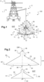
- FIG. 1 presents a recovery system 20 according to the invention.
- the figure 1 illustrates an assembly 100 comprising a carrier aircraft 1 and a carrier aircraft 10 cooperating with such a recovery system 20.
- the carrier aircraft 1 comprises a rotary wing 2.
- the figure 1 thus illustrates a helicopter but the carrier aircraft 1 could be of another type.
- aircraft 1 could also be an airplane, a rotorcraft, etc.
- the wearable aircraft 10 illustrated is a drone, namely an aircraft without an onboard human pilot.
- This drone comprises for example one or more rotors 11 rotated by motors 14.
- the motors 14 can be of all types and in particular electric motors connected to an electrical source 15 of the aircraft to be carried 10.
- this source electric 15 comprises at least one cell, at least one battery, at least one electric generator, etc.
- a control system comprising a pilot on-board automatic 13 and/or remotely controlled components can for example control the motors 14 to pilot the aircraft to be carried 10 in the usual manner.
- the recovery system 20 allows the carrier aircraft 1 to seize the aircraft to be carried 10 in flight and/or to release it in flight.
- the aircraft to be carried 10 and the recovery system 20 are possibly enlarged on the figure 1 relative to the carrier aircraft 1.
- the recovery system 20 comprises a first sub-assembly called for convenience "receiver 30" which is intended to be attached to the carrier aircraft 1.
- the receiver 30 can include a fixing called “fixing reception 40 "for convenience to be attached to the carrier aircraft 1.
- the carrier aircraft 1 may comprise a winch 3 carrying a winch cable 4.
- the receiver 30 can then be attached to the winch cable 4.
- the receiving attachment 40 may have a ring or equivalent attached to a hook 5 of the winch cable 4.
- the winch 3 then makes it possible to bring the receiver 30 closer or further away from the cell of the carrier aircraft 1.
- this cable 4 can have, outside the winch 3, a relatively large extension length so that the evolutions of the aircraft to be carried 10 are little disturbed by the air flow passing through the rotating wing 2.
- the receiver 30 may further include one or more handles 300 so that an operator can grip it more easily.
- the recovery system 20 comprises a second sub-assembly called for convenience "hook 50" intended to be secured to the aircraft to be carried 10.
- the hook 50 can be extended in elevation by a mast 55 fixed to the aircraft to carry 10 per a usual fixing member 57.
- the mast 55 is screwed to a support of the aircraft to be carried 10 in order to be secured to this aircraft to be carried 10.
- the mast 55 is dimensioned to present a segment 56 moving the aircraft to be carried 10 away from the receiver 30. Such a segment 56 extends at least partially outside the receiver 30.
- the recovery system 20 comprises a fixing device 60 having in particular the function of reversibly fixing the hook 50 to the receiver 30.
- the fixing device 60 can be controlled by a remote human operator and/or can be controlled automatically via various sensors and the like.
- the fixing device 60 can attach the hook 50 to the receiver 30 when the hook 50 is close to the receiver 30, namely in a predetermined envelope of positions relative to the receiver 30.
- the aircraft carry 10 is controlled to approach the hook 50 of the receiver 30 then the fixing device 60 secures the hook 50 to the receiver 30 when the hook 50 is in an appropriate position relative to the receiver 30.
- the aircraft to carry 10 is thus carried by the carrier aircraft 1 via the hook 50 and the receiver 30. This operation is reversible, the receiver 30 being able to release the hook 50 as is or possibly after an operation carried out by an operator, an actuator or even the aircraft to be carried 10.
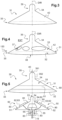
- the receiver 30 comprises an empty internal volume 38 in fluid communication with an external medium EXT at least via a passage surface 41. Therefore, the catcher 50 can penetrate into the internal volume 38 via this passage surface 41. Eye-catching 50 can also present a volume capable of being inscribed in the internal volume 38 in multiple ways.
- the receiver 30 comprises a flared guide section 31 at least partially delimiting the internal volume 38.
- This guide section 31 comprises a wall 42 provided with an internal face 32 at least partially delimiting the internal volume 38 and an external face 33 in contact with the external environment EXT.
- the flared guide section 31 has a shape extending from an annular receiving vertex 34 towards an annular receiving base 35 in an elevation direction DIR, the vertex having a radius less than a radius of the base.
- the receiving base 35 can be extended by another section opening onto the passage surface 41 or can open onto this passage surface 41 according to the example of the figure 2 .
- the guide section 31 may have a conical or frustoconical shape and/or, in an example which does not fall within the scope of the appended claims, may have a symmetry of revolution around the direction in elevation DIR.
- the guide section 31 is asymmetrical.
- the receiver 30 may comprise at least one orifice 37 putting the external environment EXT and the internal volume 38 into fluid communication, in particular in a direction 150 orthogonal to the elevation direction DIR.
- the wall 42 of the guide section may comprise one or more orifices 37 passing right through this wall 42 from the internal face 32 to its external face 33.
- the receiver 30 may include a centering portion 39 forming a centering member.
- the centering portion 39 can extend the guide section 31 in elevation in the elevation direction DIR.
- the centering portion 39 may be integral with the receiving vertex 34 of the guide section 31 or with an intermediate member interposed between the receiving vertex 34 and the centering portion 39.
- the receiving vertex 34 may form a centering portion 39
- the centering portion 39 may have a symmetry of revolution with respect to the elevation direction DIR.
- the centering portion 39 may include a bell.
- the bell may comprise a bottom 391 and a hollow cylinder 392, the bottom 391 closing one end of the cylinder 392.
- figure 8 illustrates a simple ring.
- the centering portion 39 can be integral with the receiving attachment 40.
- the receiving attachment 40 can be fixed to another member of the receiver 30, and for example to the guide section 31 or to a frame carrying the section of guidance 31.
- the hook 50 may include a flared connection section 51.
- This flared connection section 51 can possibly be contained at least partially in the internal volume 38.
- the flared connection section 51 comprises a partition provided with a flared contact face 52 capable of facing the internal face 32.
- the contact face 52 can have a conical or frustoconical shape.
- the hook 50 may include a centering finger 53.
- the centering finger 53 may be of the shape complementary to the centering portion 39 of the receiver 30.
- the centering finger 53 can be secured to the connection section 51 directly or indirectly via at least one intermediate part.
- the hook 50 can then penetrate into the internal volume 38 via the passage surface 41. Due in particular to the flared shapes, the hook 50 and for example its connection section 51 can slide along the guide section 31 until so that the centering finger 53 is inserted into the centering portion 39 and/or passes through the centering portion 39. The hook 50 is then correctly positioned in the receiver 30.
- the hook 50 and/or the receiver 30 may include at least one anti-shock member 80 called a buffer member for convenience.
- blocks of elastic material are secured to the contact face 52 of the hook 50.
- blocks of elastic material can be secured to the internal face 32 of the receiver 30.
- the recovery system 20 may comprise a fixing device 60 making it possible to reversibly fix the hook 50 to the receiver 30 and to release it if necessary.
- the fixing device 60 may include an electrical sub-assembly provided with a magnetization zone 61 secured to the receiver 30 or the hook 50.
- the magnetization zone 61 cooperates with reversible magnets 62 of the hook 50 or of the receiver 30 devoid of the magnetization zone 61.
- the fixing device 60 may comprise at least one magnetization zone 61 of the receiver 30.
- the guide section 31 comprises two frustoconical non-metallic crowns arranged in the elevation direction DIR above and below a crown frustoconical metal forming the magnetization zone 61.
- the catcher 50 then has at least one reversible magnet 62 configured to be magnetized to said at least one magnetization zone 61 of the receiver 30.
- the expression "reversible magnet” designates a member that can be temporarily magnetized and on demand to the magnetization zone.
- a reversible magnet 62 includes at least one electrically powered electromagnet if necessary.
- the hook 50 is magnetized to the receiver 30. Conversely, to release the carrier aircraft 10 the reversible magnets 62 are inhibited.
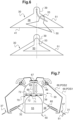
- the hook 50 comprises at least one reversible magnet called "normally closed magnet 63", and for example at least two normally closed magnets 63 equally distributed in azimuth with regard to the elevation direction DIR according to the Figure 5 .
- the catcher 50 may comprise at least one reversible magnet called "normally open magnet 64" and for example at least two normally open magnets 64 equally distributed in azimuth with regard to the elevation direction DIR according to the Figure 5 .
- Each normally open magnet 64 is magnetizable in the magnetization zone except in the event of an electrical failure of the hook and the aircraft to be carried according to this embodiment.
- each normally open magnet 64 is in communication with a positioning computer 16 and/or can be electrically connected to a source of electrical energy.
- the electrical source 15 of the aircraft to be carried represents the source of electrical energy magnetizing the reversible magnets 62.
- the positioning computer 16 can then transmit to the normally open magnets 64 a signal modifying the orientation of the magnetic field emitted by each normally open magnet 64.
- Each normally closed magnet 63 is connected to an electrically independent module 83 to be magnetizable in the event of detection of a said electrical failure, no normally open magnet 64 not cooperating with said module
- the recovery system 20 can include at least one switch 65 between said source of electrical energy 15 and each normally open magnet 64.
- a switch 65 can also be interposed for example between the module 83 and each normally closed magnet 63.
- Each switch 65 can be controlled by a remote human pilot or by an automatic system, for example depending on the position of the aircraft to be carried 10 relative to the carrier aircraft 1.
- the fixing device 60 may comprise an at least partially mechanical subassembly.
- the fixing device 60 can include at least one locking finger 66 movable relative to the guide section 31.
- at least one locking finger 66 movable relative to the guide section 31.
- four blocking fingers 66 are carried by the receiver 30 and equally distributed in azimuth around the elevation direction DIR.
- each locking finger 66 can be articulated to a support 86 of the receiver 30 by a connection pivot.
- Such support 86 can be integral with the centering portion 39 or even with the guide section 31 for example.
- the support 86 can take the form of an arm.
- Each locking finger 66 can thus rotate between a free position POS1 illustrated in dotted lines and a locking position POS2. In the free position POS1, no blocking finger 66 blocks the hook 50.
- the hook 50 is maintained according to the realization of the Figure 7 between each blocking finger 66 and an internal face 32 of the receiver 30.
- the receiver 30 can comprise an orifice 37 per blocking finger 66, each blocking finger 66 passing through a such orifice 37 to penetrate into the internal volume 38 in which the hook 50 is housed.
- Each locking finger 66 can be controlled by a motor for example. However, according to the example of the Figure 7 , each blocking finger 66 is mechanically controlled by the hook 50.
- each locking finger 66 is connected to a piston 67, a pallet of the locking finger 66 resting on the piston 67 for example.
- This piston 67 is integral with a rod 68 fixed to a plate 69 present in the internal volume, and for example in the centering portion 39. Therefore, when the hook 50 sinks into the receiver 30, the hook 50 and according to the example the centering finger 53 pushes the plate 69. This results in a translation of the piston 67 which induces the rotation of each blocking finger 66 towards its blocking position POS2. The locking fingers 66 then block the hook by bracing.
- the reversible magnets 62 can be inhibited.
- the aircraft to be carried 10 can be set in motion in order to be slightly pushed towards the high, namely towards the piston 67 to “un-button” and release the locking fingers 66.
- An actuator can also act on the locking fingers 66 for this purpose.
- a blocking finger 66 can take the form of a hook movable in rotation and actuated by a motor 88.
- the hook In the blocking position POS2, the hook can be inserted in a groove 87 and in particular under a stop of the hook 50 and in particular the centering finger 53 according to the example illustrated.
- the annular centering portion illustrated on the Figure 9 can be replaced by a bell.
- the recovery system 20 may include at least one positioning device 70 to help pilot the drone or even to possibly control a fixing device 60.
- a positioning device 70 generates a signal which varies as a function of a relative position of the catcher 50 relative to the receiver 30.
- a signal can be a digital, analog, video signal, etc.
- the positioning device 70 comprises an optical system provided with a camera 71 carried by the receiver 30.
- the positioning device 70 comprises an optical system provided with a camera 71 carried by the hook 50.
- the camera is possibly carried by the connection section 51 or the centering finger 53.
- the camera is positioned at the top of the centering finger 53.
- the optical system may include at least one target 72 carried by the receiver 30.
- three circle type targets 72 are arranged on the receiver 30.
- the geometric symbols are for example located on the centering portion 39. In the presence of a fixing device 60 according to the Figure 7 , the symbols can be arranged on plate 69.
- the optical system includes a positioning computer 16 which generates a signal according to the shape of the targets 72 visualized by the camera 71.
- the positioning computer 16 implements a usual image processing algorithm.
- the positioning calculator 16 may include for example at least one processor and at least one memory, at least one integrated circuit, at least one programmable system, at least one logic circuit, these examples not limiting the scope given to the expression “ calculator”.
- the term processor can designate as well a central processing unit known by the acronym CPU, a graphics processing unit GPU, a digital unit known by the acronym DSP, a microcontroller, etc.
- the positioning calculator 16 can be located in the aircraft to carry 10 for example.
- the positioning computer 16 can be an independent computer and/or be part of a calculation unit integrating at least one other computer and for example an automatic pilot computer 13.
- the positioning device 70 may comprise at least one proximity sensor 73.
- a proximity sensor may comprise a hall effect sensor, a push button or even a usual ultrasonic positioning system 74.
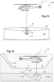
- an ultrasonic positioning system 74 may comprise ultrasonic transmitters 742 arranged on the receiver 30, and for example at the end of the conical guide section according to the Figure 10 , and ultrasound sensors 741 arranged on the hook according to the Figure 10 or on the aircraft to wear which cooperate with a drone positioning calculator.
- Such an ultrasonic positioning system 74 can make it possible to precisely direct the drone towards the receiver 30 a few tens of meters away.
- the positioning device 70 is connected to at least one switch 65 controlling at least one reversible magnet.
- FIG. 12 illustrates an exemplary embodiment of a drone according to the invention.
- an ultrasonic and or radio positioning system 74 and a camera 71 communicate with a positioning computer 16.
- This positioning computer 16 processes the data obtained to determine the position of the catcher 50 relative to the receiver 30 by example of a Kalman filter.
- the positioning computer 16 is connected to each switch 65 to transmit an order to it in order to magnetize the hook 50 to the receiver 30 when the hook 50 is in an envelope of predetermined positions.
- a position sensor can also be connected to each switch 65 without going through the positioning computer 16.
- This architecture then has two dissimilar means for controlling each switch 65, which optimizes safety.
- each switch 65 can also be in communication with a remote control 85 operable by a human operator.
- a first switch 651 makes it possible to inhibit the normally open magnets 64 on request by being arranged between the positioning computer 16 and these normally open magnets 64.
- a second switch 652 makes it possible to inhibit the normally closed magnets 63 on request by being arranged between the module 83 and these normally closed magnets 63.
- the positioning computer 16 can also communicate with an automatic pilot computer 13 which controls motors 14 or other types of control means to move the aircraft to be carried 10 in the atmosphere.
- each normally open magnet 64 is then controlled by the control computer 16.
- the control computer can send a signal to each normally open magnet 64 to change the orientation of its magnetic field or create a magnetic field.
- each normally closed magnet 63 is connected to a module 83.
- a module may include a calculator 831 or equivalent and an electrical source 832.
- the module 83 may include a usual analyzer 833 to detect whether the module 83 receives an electrical signal. If not, the module 83 transmits a signal to each normally closed magnet 63 to make it magnetizable.
- the positioning device 70 may comprise a satellite positioning system 500 integral with the aircraft to be carried and for example connected to the positioning computer 16 and/or to the automatic pilot computer 13.
- This positioning system by satellites 500 integral with the aircraft to be carried can cooperate with a satellite positioning system of the carrying aircraft and/or the receiver to precisely position the catcher relative to the receiver via a differential measurement between the satellite positioning system 500 integral with the aircraft to be carried and the satellite positioning system of the carrier aircraft and/or the receiver.
- THE figures 13 and 14 illustrate a procedure for recovering a carrier aircraft 10 of the drone type 10 with a carrier aircraft 1 of the helicopter type.
- the aircraft to be carried 10 can be authorized to fly in a restricted zone Z11.
- a restricted zone Z11 can have the shape of a cylinder with a height of 40 meters and a radius of 100 meters. The dimensions of a restricted area can be modified.
- the carrier aircraft 1 can be maneuvered to position the receiver 30 in this restricted zone Z11, for example at the top of this restricted zone Z11 and substantially on its axis of symmetry of revolution.
- the space surrounding or even present under the carrier aircraft can be divided into three zones Z1, Z2, Z3 including a secure zone Z1 in which the restricted zone Z11 is located, an intermediate zone Z2 and a danger zone Z3.
- the danger zone Z3 contains the carrier aircraft, the intermediate zone Z2 being arranged between the danger zone Z3 and the secure zone Z1.
- the aircraft to be carried 10 moves in the secure zone Z1 to reach the receiver 30.
- the aircraft to be carried can be equipped with a positioning system comprising in particular a satellite positioning system 500 and an ultrasound system 74. Therefore, the piloting computer can request the satellite positioning system 500 to direct the aircraft to be carried towards the receiver 30 as long as this satellite positioning system 500 is more precise than the ultrasonic system 74 or up to a certain distance from the receiver. Therefore, when the ultrasound system 74 becomes effective, the control is carried out in a second step using the data from the ultrasound system 74 then, if necessary, with the camera system 71 in a final phase.
- a positioning system comprising in particular a satellite positioning system 500 and an ultrasound system 74. Therefore, the piloting computer can request the satellite positioning system 500 to direct the aircraft to be carried towards the receiver 30 as long as this satellite positioning system 500 is more precise than the ultrasonic system 74 or up to a certain distance from the receiver. Therefore, when the ultrasound system 74 becomes effective, the control is carried out in a second step using the data from the ultrasound system 74 then, if necessary, with the camera system 71 in a
- the aircraft to be carried 1 evolves in the intermediate zone Z2 for example following a gust of wind
- automatic orders developed by one or more memorized laws of the piloting computer and/or given by an operator are generated and transmitted to the control organs.
- a new waypoint located on the ground is generated to force the drone to return to the secure zone Z1.
- an order may take the form of a signal ordering the drone's engines to be cut off.
- a signal can be transmitted to a parachute system to deploy at least one parachute, this parachute can for example be controlled according to the teaching of the request for patent FR 3074144 .
- a receiver comprising only a magnetization zone and not blocking fingers or only at least one blocking finger.
- a magnetization zone on the catcher and reversible magnets on the receiver.
- the catcher and the receiver each have a magnetization zone and reversible magnets.
Description
La présente invention concerne un système de récupération voire de largage pour porter un aéronef avec un autre aéronef. L'invention se situe donc dans le domaine technique des aéronefs.The present invention relates to a recovery or even release system for carrying an aircraft with another aircraft. The invention therefore lies in the technical field of aircraft.
Parmi les aéronefs, les hélicoptères ou équivalents possèdent une grande autonomie mais sont volumineux, onéreux et soumis à des contraintes de navigation visant à assurer la sécurité de leurs occupants. De plus, un hélicoptère ne peut pas évoluer dans certains espaces aériens pour préserver la sécurité de ces occupants, par exemple lorsque le relief est susceptible de conduire à un accident voire lorsque l'atmosphère est contaminée notamment par des éléments chimiquement dangereux, des bactéries ou encore des éléments radioactifs suite à un incident.Among aircraft, helicopters or equivalents have great autonomy but are bulky, expensive and subject to navigation constraints aimed at ensuring the safety of their occupants. Furthermore, a helicopter cannot operate in certain airspaces to preserve the safety of its occupants, for example when the terrain is likely to lead to an accident or even when the atmosphere is contaminated in particular by chemically dangerous elements, bacteria or still radioactive elements following an incident.
Par ailleurs, les drones sont des aéronefs sans pilote embarqué possédant une autonomie restreinte. Néanmoins, certains drones présentent un encombrement restreint leur permettant d'évoluer à proximité de reliefs dangereux. Les drones peuvent être pilotés par un pilote humain à distance ou par un pilote automatique embarqué ou distant par exemple pour évoluer dans un environnement pollué dangereux pour l'homme.Furthermore, drones are unmanned aircraft with limited autonomy. However, some drones have a limited footprint allowing them to operate near dangerous terrain. Drones can be piloted by a remote human pilot or by an on-board or remote autopilot, for example to operate in a polluted environment dangerous for humans.
Ces deux types d'aéronefs peuvent être complémentaires.These two types of aircraft can be complementary.
En effet, un aéronef dénommé par commodité « aéronef porteur » peut porter en vol un autre aéronef dénommé par commodité « aéronef à porter ». Par exemple un hélicoptère peut être équipé d'un drone largable et/ou récupérable en vol. Pour diverses missions, le drone peut être le prolongement de l'aéronef porteur. Selon un exemple, un hélicoptère peut couvrir une distance relativement longue pour acheminer un drone au plus près d'une zone à explorer où s'est produit un accident. Cette zone peut être éventuellement inaccessible pour l'hélicoptère pour des raisons de sécurité des personnes embarquées dans cet hélicoptère, des questions d'accessibilité,.... A destination, le drone est alors largué pour explorer la zone de manière sécurisée puis est éventuellement récupéré par l'hélicoptère.Indeed, an aircraft called for convenience “carrying aircraft” can carry in flight another aircraft called for convenience “carrying aircraft”. For example, a helicopter can be equipped with a drone that can be released and/or recovered in flight. For various missions, the drone can be an extension of the carrier aircraft. According to one example, a helicopter can cover a relatively long distance to bring a drone as close as possible to an area to be explored where an accident has occurred. This area may possibly be inaccessible to the helicopter for reasons of safety of the people embarked in this helicopter, questions of accessibility, etc. At destination, the drone is then released to explore the area in a secure manner and is eventually recovered by the helicopter.
En larguant un drone depuis un hélicoptère, on s'affranchit donc des limitations liées à la faible autonomie de ce drone.By dropping a drone from a helicopter, we therefore overcome the limitations linked to the low autonomy of this drone.
En outre, la récupération du drone avec l'hélicoptère peut être intéressante, par exemple pour le ravitailler en carburant ou en énergie électrique avec rechargement à bord au cours de la mission, voire pour récupérer du matériel transporté par ce drone.In addition, recovering the drone with the helicopter can be interesting, for example to resupply it with fuel or electrical energy with recharging on board during the mission, or even to recover equipment transported by this drone.
Cependant, une telle récupération peut être délicate. En particulier, le contrôle du drone dans un environnement perturbé par le souffle du rotor de sustentation d'un hélicoptère est difficile. En effet, le rotor principal de sustentation d'un hélicoptère est traversé par un flux d'air, ce flux d'air perturbant les conditions de vol à l'intérieur d'un volume survolé par l'hélicoptère. En complément, plus un drone est léger, plus sa trajectoire de vol est incertaine dans un tel volume perturbé par le flux d'air traversant le rotor de sustentation de l'hélicoptère.However, such recovery can be tricky. In particular, controlling the drone in an environment disturbed by the blast of the lift rotor of a helicopter is difficult. In fact, the main lift rotor of a helicopter is crossed by a flow of air, this air flow disrupting the flight conditions inside a volume flown over by the helicopter. In addition, the lighter a drone is, the more uncertain its flight trajectory is in such a volume disturbed by the air flow passing through the helicopter's lift rotor.
Outre les conditions de vol difficiles que l'on peut rencontrer à proximité d'un hélicoptère, munir un drone d'un dispositif de pilotage précis pour faciliter sa récupération en vol peut s'avérer onéreux. De plus, un tel dispositif de pilotage peut être encombrant et posséder une masse non négligeable.In addition to the difficult flight conditions that can be encountered near a helicopter, equipping a drone with a precise control device to facilitate its recovery in flight can be expensive. In addition, such a control device can be bulky and have a significant mass.
Parmi l'état de la technique, on connaît des dispositifs pour lancer un aéronef à partir d'une plateforme mobile.Among the state of the art, devices are known for launching an aircraft from a mobile platform.
Par exemple, le document
Par ailleurs, il existe des dispositifs mettant en oeuvre des crochets d'ancrage ou de simples filets pour récupérer des drones en vol.Furthermore, there are devices using anchor hooks or simple nets to recover drones in flight.
De même, on connaît des méthodes d'approche positionnant un drone à l'aplomb d'une zone d'atterrissage. On peut par exemple se référer au document
Par ailleurs, l'état de la technique inclut aussi les documents
Le document
Le document
En outre, le document
La présente invention a alors pour objet de proposer un système de récupération voire de largage d'un drone, simple à mettre en oeuvre, et par exemple applicable sur un aéronef de type hélicoptère.The object of the present invention is therefore to propose a system for recovering or even releasing a drone, simple to implement, and for example applicable to a helicopter type aircraft.
L'invention vise un système de récupération pour au moins récupérer, voire larguer, en vol un aéronef à porter à partir d'un aéronef porteur, le système de récupération comprenant un récepteur apte à être porté par l'aéronef porteur et un accrocheur apte à être porté par l'aéronef à porter, ledit récepteur présentant un volume interne débouchant sur un milieu extérieur par une surface de passage, ledit récepteur comportant un tronçon de guidage creux, ledit tronçon de guidage étant évasé.The invention aims at a recovery system for at least recovering, or even releasing, in flight an aircraft to be carried from a carrier aircraft, the recovery system comprising a receiver capable of being carried by the carrier aircraft and a hook capable of to be carried by the aircraft to be carried, said receiver having an internal volume opening onto an external environment via a passage surface, said receiver comprising a hollow guide section, said guide section being flared.
Par exemple, l'aéronef à porter est un aéronef sans pilote embarqué. Selon un exemple, l'aéronef porteur est un aéronef apte voler à « basse vitesse » et par exemple à moins de 50 noeuds et/ou comportant une voilure tournante. L'aéronef porteur peut être un aéronef muni d'au moins un pilote humain et/ou automatique.For example, the aircraft to be carried is an aircraft without an onboard pilot. According to one example, the carrier aircraft is an aircraft capable of flying at “low speed” and for example at less than 50 knots and/or comprising a rotating wing. The carrier aircraft may be an aircraft equipped with at least one human and/or automatic pilot.
Le système peut éventuellement comprendre une ou plusieurs des caractéristiques qui suivent.The system may optionally include one or more of the following features.
Selon un aspect, l'accrocheur peut comporter un tronçon de connexion évasé apte à être contenu au moins partiellement dans ledit volume interne, le système de récupération comprenant un dispositif de fixation fixant de manière réversible l'accrocheur au récepteur, par exemple dans des conditions prédéterminées. De telles conditions prédéterminées peuvent comporter une position prédéterminée ou une enveloppe prédéterminée de positions de l'accrocheur par rapport au récepteur.According to one aspect, the hook may comprise a flared connection section capable of being contained at least partially in said internal volume, the recovery system comprising a fixing device reversibly fixing the hook to the receiver, for example under conditions predetermined. Such predetermined conditions may include a predetermined position or a predetermined envelope of positions of the catcher relative to the receiver.
Eventuellement, ledit tronçon de connexion voire l'accrocheur sont inscrits dans un volume d'accrochage apte à être contenu intégralement dans le volume interne du récepteur de part leurs volumes et leurs formes.Optionally, said connection section or even the hook are inscribed in a hooking volume capable of being contained entirely in the internal volume of the receiver due to their volumes and their shapes.
Selon un aspect, le récepteur peut être accroché à l'aéronef porteur. A cet effet, le récepteur peut comprendre une fixation arrangée par exemple en dehors du volume interne du récepteur. Cette fixation peut être fixée à l'aéronef porteur. En particulier, le récepteur peut être attaché à un câble qui est attaché à une potence ou encore à un treuil... Le cas échéant les interfaces treuils usuelles peuvent être conservées afin de laisser toute sa polyvalence de mission à l'aéronef porteur. Dans ce cas de figure, le récepteur peut représenter un lest visant à maintenir le câble sensiblement tendu pour par exemple éviter un mouvement de remontée du câble vers l'aéronef porteur suite à un largage.According to one aspect, the receiver can be attached to the carrier aircraft. For this purpose, the receiver may comprise a fixation arranged for example outside the internal volume of the receiver. This attachment can be attached to the carrier aircraft. In particular, the receiver can be attached to a cable which is attached to a jib or even to a winch... If necessary, the usual winch interfaces can be retained in order to leave all its mission versatility to the carrier aircraft. In this scenario, the receiver can represent ballast aimed at keeping the cable substantially taut to, for example, prevent the cable from rising towards the carrier aircraft following a release.
Par ailleurs, le récepteur et l'accrocheur peuvent présenter chacun un tronçon ayant une forme évasée. Cette forme permet d'optimiser la captation de l'accrocheur par le récepteur sous de nombreuses conditions de vol. En particulier, le récepteur peut capter un accrocheur d'un drone durant une phase de vol stationnaire de l'aéronef porteur mais aussi durant un vol d'avancement. Eventuellement, la récupération d'un drone est réalisée durant un vol de translation de l'aéronef porteur pour éviter qu'un câble portant le récepteur ballote. L'assiette de l'aéronef à porter muni de l'accrocheur peut être pilotée pour être sensiblement parallèle à la surface de passage.Furthermore, the receiver and the hook can each have a section having a flared shape. This shape makes it possible to optimize the capture of the catcher by the receiver under numerous flight conditions. In particular, the receiver can capture an eye-catcher from a drone during a hovering flight phase of the carrier aircraft but also during an advancing flight. Optionally, the recovery of a drone is carried out during a translation flight of the carrier aircraft to prevent a cable carrying the receiver from bouncing around. The attitude of the aircraft to be carried equipped with the hook can be controlled to be substantially parallel to the passage surface.
Selon un exemple, le tronçon de connexion et le tronçon de guidage ont chacun une forme qui s'évase sensiblement selon une direction allant de l'aéronef vers le sol et par exemple conique ou tronconique, la forme du tronçon de connexion étant plus petite que la forme du tronçon de guidage.According to one example, the connection section and the guide section each have a shape which flares substantially in a direction going from the aircraft towards the ground and for example conical or frustoconical, the shape of the connection section being smaller than the shape of the guide section.
Selon un aspect, le récepteur peut comporter au moins un orifice traversant de part en part une paroi de ce récepteur, cet orifice mettant en communication fluidique ledit milieu extérieur et ledit volume interne.According to one aspect, the receiver may comprise at least one orifice passing right through a wall of this receiver, this orifice putting said external medium and said internal volume into fluid communication.
Un tel orifice peut notamment permettre à l'air extérieur de s'écouler du milieu extérieur vers le volume interne afin de stabiliser le récepteur en vol.Such an orifice can in particular allow external air to flow from the external environment towards the internal volume in order to stabilize the receiver in flight.
Le tronçon de guidage est asymétrique.The guide section is asymmetrical.
Le tronçon de guidage a une forme asymétrique notamment dépourvue d'une symétrie de révolution contrairement à une forme strictement conique ou tronconique pour prendre en considération un basculement du récepteur lors d'un vol d'avancement. Une forme asymétrique peut tendre à limiter les risques de ballotement du récepteur lors d'un vol d'avancement.The guide section has an asymmetrical shape in particular devoid of symmetry of revolution unlike a strictly conical or frustoconical shape to take into consideration a tilting of the receiver during an advancing flight. An asymmetrical shape can tend to limit the risk of the receiver swinging during forward flight.
Alternativement, dans un exemple qui n'entre pas dans le champ d'application des revendications annexées, le tronçon de guidage peut présenter une symétrie de révolution. Le système de récupération peut être dimensionné pour autoriser une dérive prédéterminée du récepteur en vol d'avancement qui force le câble éventuel et le récepteur à suivre une trajectoire « propre », à savoir avec un déplacement en rotation selon l'axe du câble du treuil éventuel restreint à quelques degrés et/ou avec un ballottement latéral ou avant-arrière réduit à quelques degrés.Alternatively, in an example which does not fall within the scope of the appended claims, the guide section may have revolution symmetry. The recovery system can be dimensioned to allow a predetermined drift of the receiver in forward flight which forces the possible cable and the receiver to follow a “clean” trajectory, namely with a rotational movement along the axis of the winch cable possibly restricted to a few degrees and/or with lateral or front-to-back sway reduced to a few degrees.
Selon un aspect, le récepteur peut comporter une portion de centrage solidaire d'un sommet de réception du tronçon de guidage, ledit accrocheur comportant un doigt de centrage éventuellement solidaire d'un sommet de connexion dudit tronçon de connexion, le doigt de centrage étant configuré pour pénétrer dans ladite portion de centrage.According to one aspect, the receiver may comprise a centering portion secured to a receiving vertex of the guide section, said catcher comprising a centering finger possibly secured to a connection vertex of said connection section, the centering finger being configured to penetrate said centering portion.
L'accrocheur comporte donc un doigt de centrage d'une forme sensiblement complémentaire à la portion de centrage. Dès lors, l'accrocheur peut se déplacer, voire glisser, dans le tronçon de guidage jusqu'à ce que le doigt de centrage prenne sa place dans la portion de centrage. Lorsque le doigt de centrage est disposé dans la portion de centrage, l'accrocheur est correctement positionné au sein du récepteur au moins horizontalement.The hook therefore comprises a centering finger of a shape substantially complementary to the centering portion. From then on, the hook can move, or even slide, in the guide section until the centering finger takes its place in the centering portion. When the centering finger is positioned in the centering portion, the hook is correctly positioned within the receiver at least horizontally.
Selon un exemple, la portion de centrage comporte un anneau.According to one example, the centering portion comprises a ring.
Selon un exemple, le récepteur peut posséder une portion de centrage en forme de cloche qui surmonte le tronçon de guidage, la cloche délimitant partiellement le volume interne. Par exemple, le volume interne peut être décomposé en un volume inférieur délimité par le tronçon de guidage et un volume supérieur délimité par la cloche. La cloche permet éventuellement de positionner l'accrocheur horizontalement via les bords de cette cloche voire verticalement via le fond de la cloche.According to one example, the receiver may have a bell-shaped centering portion which overcomes the guide section, the bell partially delimiting the internal volume. For example, the internal volume can be broken down into a lower volume delimited by the guide section and an upper volume delimited by the bell. The bell optionally allows the hanger to be positioned horizontally via the edges of this bell or even vertically via the bottom of the bell.
Selon un aspect, ledit accrocheur peut être solidaire d'un mât configuré pour être attaché à l'aéronef à porter, ledit mât comprenant un segment agencé en dehors dudit récepteur lorsque ledit accrocheur est arrimé au récepteur.According to one aspect, said hook can be integral with a mast configured to be attached to the aircraft to be carried, said mast comprising a segment arranged outside of said receiver when said hook is secured to the receiver.
Le mât permet d'éloigner l'aéronef à porter du récepteur pour éviter tout contact entre cet aéronef à porter et le récepteur.The mast makes it possible to move the aircraft to be carried away from the receiver to avoid any contact between this aircraft to be carried and the receiver.
Par exemple, le mât s'étend selon une direction d'extension sur une longueur de mât supérieure à une hauteur du récepteur selon ladite direction d'extension. Le cas échéant, la direction d'extension peut représenter un axe de symétrie de révolution d'une portion de centrage du récepteur.For example, the mast extends in an extension direction over a mast length greater than a height of the receiver in said extension direction. Where appropriate, the direction of extension may represent an axis of symmetry of revolution of a centering portion of the receiver.
Selon un aspect, au moins ledit accrocheur ou ledit récepteur peut comporter au moins un organe tampon configuré pour limiter les conséquences d'un contact entre l'accrocheur et le récepteur. Autrement dit, l'accrocheur et/ou le récepteur peuvent comporter au moins un organe tampon.According to one aspect, at least said hook or said receiver may comprise at least one buffer member configured to limit the consequences of contact between the hook and the receiver. In other words, the catcher and/or the receiver may include at least one buffer member.
Par exemple, l'organe tampon peut comprendre un bloc en une matière élastique, de l'élastomère par exemple. L'organe tampon peut être fixé à une face interne du récepteur délimitant le volume interne ou à une face externe de l'accrocheur.For example, the buffer member may comprise a block made of an elastic material, elastomer for example. The buffer member can be fixed to an internal face of the receiver delimiting the internal volume or to an external face of the hook.
Selon un aspect, ledit dispositif de fixation peut comporter au moins une zone d'aimantation solidaire de l'accrocheur ou du récepteur, ledit dispositif de fixation ayant au moins un aimant réversible solidaire de l'accrocheur ou du récepteur dépourvu de la zone d'aimantation, ledit au moins un aimant réversible étant apte à être aimanté ou pas aimanté à ladite au moins une zone d'aimantation sur commande.According to one aspect, said fixing device may comprise at least one magnetization zone secured to the catcher or the receiver, said fixing device having at least one reversible magnet secured to the catcher or the receiver devoid of the magnetization zone. magnetization, said at least one reversible magnet being capable of being magnetized or not magnetized to said at least one magnetization zone on command.
Par exemple, le récepteur peut donc avoir une zone d'aimantation pouvant être aimantée à au moins un aimant réversible de l'accrocheur pour fixer cet accrocheur au récepteur sur ordre d'un organe de commande.For example, the receiver can therefore have a magnetization zone which can be magnetized to at least one reversible magnet of the hook to fix this hook to the receiver on the order of a control member.
La commande d'au moins certains aimants réversibles peut se faire manuellement au travers d'un opérateur présent au sol ou embarqué à bord de l'aéronef porteur, par exemple, mais aussi peut être émise en totale autonomie par un calculateur éventuellement suite à une détection de position par un système de positionnement.The control of at least certain reversible magnets can be done manually through an operator present on the ground or on board the carrier aircraft, for example, but can also be issued in total autonomy by a computer possibly following a position detection by a positioning system.
Un organe tampon peut notamment être intéressant en cas d'utilisation d'aimants réversibles générant des champs magnétiques importants capables de rapprocher violemment l'accrocheur du récepteur.A buffer member may in particular be of interest in the case of the use of reversible magnets generating significant magnetic fields capable of violently bringing the catcher closer to the receiver.
Par exemple, cet au moins un aimant réversible peut comporter au moins un aimant normalement ouvert qui est aimantable à la zone d'aimantation hors cas de panne électrique, ledit au moins un aimant réversible comportant au moins un aimant normalement fermé qui est aimantable à la zone d'aimantation par un module électriquement autonome en cas de détection d'une panne électrique, ledit au moins un aimant réversible normalement ouvert ne coopérant pas avec ledit module.For example, this at least one reversible magnet may comprise at least one normally open magnet which is magnetizable in the magnetization zone except in the event of an electrical failure, said at least one reversible magnet comprising at least one normally open magnet. closed which is magnetizable to the magnetization zone by an electrically autonomous module in the event of detection of an electrical failure, said at least one normally open reversible magnet not cooperating with said module.
Le terme « aimantable » qualifie par la suite un aimant réversible générant un champ magnétique dans une direction permettant d'aimanter cet aimant réversible à la zone d'aimantation.The term “magnetizable” subsequently qualifies a reversible magnet generating a magnetic field in a direction making it possible to magnetize this reversible magnet to the magnetization zone.
Chaque aimant réversible peur par exemple comprendre un système à électroaimant générant un champ magnétique à orientation variable. Ainsi, un tel aimant réversible peut être aimantable ou non aimantable à la zone d'aimantation en fonction de l'orientation du champ magnétique qu'il génère.Each reversible magnet can, for example, include an electromagnet system generating a magnetic field with variable orientation. Thus, such a reversible magnet can be magnetizable or non-magnetizable at the magnetization zone depending on the orientation of the magnetic field that it generates.
Par exemple, chaque aimant réversible peut comprendre un système connu sous la dénomination commerciale « OpenGrab EPM V3 R5C » et commercialisé par « nicadrone ».For example, each reversible magnet may include a system known under the trade name “OpenGrab EPM V3 R5C” and marketed by “nicadrone”.
Avec une architecture de ce type, même en cas de panne électrique d'un réseau électrique principal, au moins un aimant réversible peut être aimanté lors d'une phase d'arrimage de l'accrocheur au récepteur.With an architecture of this type, even in the event of a power failure in a main electrical network, at least one reversible magnet can be magnetized during a docking phase of the catcher to the receiver.
Une source électrique d'un tel réseau peut alimenter électriquement directement ou indirectement chaque aimant réversible normalement ouvert. Cette source électrique peut permettre dans des conditions normales d'aimanter si besoin les aimants normalement ouverts afin de solidariser un accrocheur à un récepteur. La source d'énergie électrique peut comprendre au moins une source électrique de l'aéronef à porter lorsque les aimants réversibles sont sur l'accrocheur. La source d'énergie électrique peut comprendre une pile, une batterie, un générateur électrique...An electrical source of such a network can electrically power each normally open reversible magnet directly or indirectly. This electrical source can make it possible, under normal conditions, to magnetize normally open magnets if necessary in order to secure a catcher to a receiver. The electrical power source may include at least one electrical source of the aircraft to be worn when the reversible magnets are on the hook. The source of electrical energy may include a cell, a battery, an electrical generator, etc.
Le module relié aux aimants normalement fermés peut comporter sa propre réserve d'énergie électrique, telle qu'une pile, une batterie, un générateur électriqueThe module connected to the normally closed magnets may include its own reserve of electrical energy, such as a cell, a battery, an electric generator
Eventuellement, le système de récupération peut comporter au moins un interrupteur pour inhiber ledit au moins un aimant normalement fermé et/ou ledit au moins un aimant normalement ouvert. Le terme « inhiber » signifie que l'aimant réversible inhibé ne produit pas un champ magnétique permettant de l'aimanter à la zone d'aimantation.Optionally, the recovery system may include at least one switch to inhibit said at least one normally closed magnet and/or said at least one normally open magnet. The term “inhibit” means that the inhibited reversible magnet does not produce a magnetic field allowing it to be magnetized to the magnetization zone.
L'interrupteur peut être soit commandé par un calculateur de l'aéronef à porter en fonction d'une loi mémorisée ou d'un équivalent soit commandé par un pilote non embarqué par exemple. Par exemple, un interrupteur peut couper une ligne électrique débouchant sur un aimant réversible ou peut générer un ordre transmis audit module.The switch can either be controlled by a computer of the aircraft to be carried according to a memorized law or an equivalent or controlled by an off-board pilot for example. For example, a switch can cut an electrical line leading to a reversible magnet or can generate an order transmitted to said module.
Durant le vol de l'aéronef à porter, chaque interrupteur peut ainsi être activé pour inhiber les aimants réversibles. Par conséquent, les aimants normalement ouverts et normalement fermés sont par exemple réglés pour générer chacun un champ magnétique qui ne permet pas de l'aimanter à la zone d'aimantation, indépendamment de la position de l'accrocheur par rapport au récepteur.During the flight of the aircraft to be worn, each switch can thus be activated to inhibit the reversible magnets. Consequently, the normally open and normally closed magnets are for example adjusted to each generate a magnetic field which does not allow it to be magnetized to the magnetization zone, independently of the position of the catcher relative to the receiver.
Durant une phase d'arrimage, chaque interrupteur peut être sollicité pour activer le système d'aimantation.During a docking phase, each switch can be used to activate the magnetization system.
Lorsque l'accrocheur peut être arrimé au récepteur, les aimants normalement ouverts sont commandés pour modifier l'orientation de leurs champs magnétiques afin de pouvoir être fixés à la zone d'aimantation. A l'inverse, les aimants normalement fermés ne reçoivent aucun ordre et restent non aimantables à la zone d'aimantation.When the catcher can be docked to the receiver, the normally open magnets are commanded to change the orientation of their magnetic fields so that they can be attached to the magnetization area. Conversely, normally closed magnets do not receive any command and remain non-magnetizable in the magnetization zone.
En cas de panne électrique du réseau reliant la source d'énergie électrique aux aimants normalement ouverts, les aimants normalement ouverts restent le cas échéant aimantables à la zone d'aimantation. Par contre, le module peut détecter une telle panne par exemple en détectant l'absence d'un courant électrique à ses bornes. Le module étant indépendant électriquement, ce module commande les aimants normalement fermés pour les rendre aimantables à la zone d'aimantation. Par exemple, le module transmet un signal électrique à chaque aimant normalement fermé à cet effet.In the event of an electrical breakdown in the network connecting the source of electrical energy to the normally open magnets, the normally open magnets remain magnetizable in the magnetization zone, if necessary. On the other hand, the module can detect such a failure, for example by detecting the absence of an electric current at its terminals. The module being electrically independent, this module controls the normally closed magnets to make them magnetizable in the magnetization zone. For example, the module transmits an electrical signal to each normally closed magnet for this purpose.
De manière complémentaire ou alternative, le dispositif de fixation peut comporter au moins un doigt de blocage mobile par rapport au tronçon de guidage, ledit doigt de blocage étant mobile entre une position libre dans laquelle le doigt de blocage n'entrave pas l'accrocheur et une position de blocage dans laquelle ledit accrocheur est maintenu au moins par le doigt de blocage.Complementarily or alternatively, the fixing device may comprise at least one locking finger movable relative to the guide section, said locking finger being movable between a free position in which the locking finger does not hinder the hook and a blocking position in which said hook is held at least by the blocking finger.
Le ou les doigts de blocage sont portés par le récepteur. Par exemple, le ou les doigts de blocage sont portés chacun articulés à un soutien du récepteur par une liaison, et par exemple par une liaison pivot.The blocking finger(s) are carried by the receiver. For example, the locking finger(s) are each articulated to a support of the receiver by a connection, and for example by a pivot connection.
L'expression « doigt de blocage » désigne un organe apte à bloquer l'accrocheur par exemple par interférence de forme. Par exemple, un doigt de blocage peut prendre la forme d'un bras apte à s'arc-bouter ou d'un crochet apte à s'insérer dans une gorge ou un équivalent.The expression “blocking finger” designates an organ capable of blocking the hook, for example by interference of shape. For example, a locking finger can take the form of an arm capable of bracing or of a hook capable of being inserted into a groove or an equivalent.
Eventuellement, le tronçon de guidage peut comporter une découpe par doigt de blocage, chaque doigt de blocage traversant la découpe au moins dans la position de blocage dans laquelle le doigt de blocage coince l'accrocheur. Une telle découpe peut prendre la forme d'un orifice précité.Optionally, the guide section may include a cutout using a locking finger, each locking finger passing through the cutout at least in the locking position in which the locking finger jams the hook. Such a cutout can take the form of a aforementioned orifice.
Chaque doigt de blocage peut coopérer avec le récepteur pour former une pince afin de réaliser un arrêt positif entre le récepteur et l'accrocheur.Each blocking finger can cooperate with the receiver to form a clamp to provide a positive stop between the receiver and the catcher.
Chaque doigt de blocage peut être motorisé ou encore commandé mécaniquement par l'accrocheur en tant que tel.Each locking finger can be motorized or mechanically controlled by the hook itself.
Par exemple, le doigt de blocage peut être commandé mécaniquement par l'accrocheur au moins pour passer de la position libre à la position de blocage, ledit doigt de blocage étant relié à un piston mobile en translation pour qu'une translation du piston induite par l'accrocheur engendre une rotation du doigt de blocage.For example, the blocking finger can be mechanically controlled by the hook at least to move from the free position to the blocking position, said blocking finger being connected to a piston movable in translation so that a translation of the piston induced by the hook generates a rotation of the blocking finger.
Un exemple de dispositif de fixation comporte ainsi un piston poussé par l'accrocheur. Ce piston peut être relié mécaniquement à au moins un doigt de blocage afin de basculer directement ou indirectement ce doigt de blocage. La translation du piston induit le passage de chaque doigt de blocage au travers du récepteur et notamment du tronçon de guidage pour verrouiller l'accrocheur au récepteur. Eventuellement, lorsque ce dispositif est associé à des organes aimantables, ce dispositif peut être dimensionné pour pincer l'accrocheur après la mise en oeuvre des organes aimantables. Pour permettre le largage suivant de l'aéronef à porter, les doigts de blocage peuvent être déverrouillés par un opérateur humain présent dans l'aéronef porteur, et/ou par des actionneurs et éventuellement les mêmes actionneurs qui ont permis de placer les doigts de blocage dans la position de blocage et/ou suite à une action de l'aéronef à porter.An example of a fixing device thus comprises a piston pushed by the hook. This piston can be mechanically connected to at least one locking finger in order to directly or indirectly tilt this locking finger. The translation of the piston induces the passage of each locking finger through the receiver and in particular the guide section to lock the hook to the receiver. Optionally, when this device is associated with magnetizable members, this device can be dimensioned to pinch the hook after the implementation of the magnetizable members. To allow the subsequent release of the aircraft to be carried, the locking fingers can be unlocked by a human operator present in the carrying aircraft, and/or by actuators and possibly the same actuators which made it possible to place the locking fingers in the blocking position and/or following an action by the aircraft to be carried.
Selon un autre exemple, un doigt de blocage peut prendre la forme d'un crochet mobile par exemple en rotation pour s'insérer dans une gorge du doigt de centrage afin de bloquer verticalement et / ou horizontalement l'accrocheur. Un tel crochet peut être commandé par un moteur ou mécaniquement sans moteur et par exemple par l'accrocheur.According to another example, a blocking finger can take the form of a movable hook, for example in rotation, to be inserted into a groove of the centering finger in order to block the hook vertically and/or horizontally. Such a hook can be controlled by a motor or mechanically without a motor and for example by the catcher.
Selon un aspect, ledit système de récupération peut comporter au moins un dispositif de positionnement générant un signal qui varie en fonction d'une position relative de l'accrocheur par rapport au récepteur.According to one aspect, said recovery system may comprise at least one positioning device generating a signal which varies as a function of a relative position of the catcher relative to the receiver.
Un tel dispositif de positionnement peut fournir une aide, pour piloter l'aéronef à porter, à un pilote humain déporté ou à un pilote automatique de l'aéronef à porter. Le dispositif de positionnement peut aussi commander le système de fixation dès que l'accrocheur est correctement positionné. Par exemple, un calculateur de positionnement peut à partir d'une certaine distance commander une aimantation progressive ou sensiblement instantanée des aimants réversibles précités.Such a positioning device can provide assistance, in piloting the aircraft to be carried, to a remote human pilot or to an automatic pilot of the aircraft to be carried. The positioning device can also control the fixing system as soon as the hook is correctly positioned. For example, a positioning computer can, from a certain distance, control progressive or substantially instantaneous magnetization of the aforementioned reversible magnets.
Par exemple, le récepteur et/ou l'accrocheur peuvent posséder des zones réservées pour intégrer divers capteurs du dispositif de positionnement.For example, the receiver and/or the catcher may have areas reserved for integrating various sensors of the positioning device.
Selon un aspect, le dispositif de positionnement peut comporter au moins une caméra et/ou au moins un calculateur de positionnement et/ou au moins une cible portée par le récepteur.According to one aspect, the positioning device may comprise at least one camera and/or at least one positioning calculator and/or at least one target carried by the receiver.
Selon un aspect, le dispositif de positionnement peut comporter une caméra portée par l'accrocheur ainsi qu'un calculateur de positionnement relié à ladite caméra et au moins une cible portée par le récepteur.According to one aspect, the positioning device may include a camera carried by the catcher as well as a positioning calculator connected to said camera and at least one target carried by the receiver.
La caméra peut être par exemple agencée le cas échéant sur le doigt de centrage de l'accrocheur.The camera can, for example, be arranged, if necessary, on the centering finger of the catcher.
Le calculateur de positionnement peut appliquer des algorithmes connus pour déterminer la position de l'accrocheur par rapport au récepteur à l'aide d'images de la cible saisies par la caméra. Par exemple, un algorithme connu sous l'expression anglaise « vision computing » avec OPEN CV ou encore un réseau de neurones de type connu sous l'expression « Deep learning » peuvent être utilisés pour reconnaitre la présence de l'accrocheur et déclencher l'ordre de verrouillage. Par exemple, la cible peut comprendre au moins un symbole géométrique et éventuellement au moins un cercle, le calculateur de positionnement déterminant la position de l'accrocheur en fonction de la forme du symbole capté avec la caméra au regard du cercle théoriquement observé lorsque l'accrocheur est correctement positionné. La littérature détaille un tel procédé.The positioning calculator can apply known algorithms to determine the position of the hook relative to the receiver using images of the target captured by the camera. For example, an algorithm known under the English expression "vision computing" with OPEN CV or even a neural network of the type known under the expression "Deep learning" can be used to recognize the presence of the catchy and trigger the lock order. For example, the target may comprise at least one geometric symbol and possibly at least one circle, the positioning calculator determining the position of the catcher according to the shape of the symbol captured with the camera with regard to the circle theoretically observed when the eye-catching is correctly positioned. The literature details such a process.
Selon un autre aspect, le récepteur peut comprendre une caméra évaluant la position de l'accrocheur. Par exemple, un calculateur de positionnement exploite les images transmises pas la caméra pour déterminer si un doigt de centrage de l'accrocheur est passé au travers d'un orifice de centrage du récepteur et commander en conséquence le déplacement de chaque doigt de blocage. Des algorithmes de type « computer vision » ou « deep learning » sont envisageables par exemple.In another aspect, the receiver may include a camera evaluating the position of the catcher. For example, a positioning calculator uses the images transmitted by the camera to determine whether a centering finger of the catcher has passed through a centering orifice of the receiver and accordingly control the movement of each blocking finger. “Computer vision” or “deep learning” type algorithms are possible, for example.
De manière alternative ou complémentaire, le dispositif de positionnement peut comporter un capteur de proximité. Un tel capteur de proximité peut par exemple comprendre un système à ultrasons, un capteur à effet hall, un bouton poussoir...Alternatively or additionally, the positioning device may include a proximity sensor. Such a proximity sensor can for example include an ultrasonic system, a hall effect sensor, a push button, etc.
Selon un autre aspect, le récepteur et/ou l'accrocheur et/ou l'aéronef à porter peut comprendre une ou plusieurs centrales inertiellesAccording to another aspect, the receiver and/or the catcher and/or the aircraft to be worn may comprise one or more inertial units
Selon un aspect, un dispositif de positionnement peut le cas échéant être relié à l'interrupteur commandant des aimants réversibles.According to one aspect, a positioning device can where appropriate be connected to the switch controlling the reversible magnets.
Outre un système de récupération, l'invention vise un ensemble muni d'un aéronef porteur et d'un aéronef à porter, le récepteur étant accroché à l'aéronef porteur et l'accrocheur étant accroché à l'aéronef à porter.In addition to a recovery system, the invention relates to an assembly provided with a carrier aircraft and an aircraft to be carried, the receiver being attached to the carrier aircraft and the hook being attached to the aircraft to be carried.
L'invention et ses avantages apparaîtront avec plus de détails dans le cadre de la description qui suit avec des exemples donnés à titre illustratif en référence aux figures annexées qui représentent :
- [
Fig 1 ] lafigure 1 , un schéma illustrant un ensemble comprenant un aéronef à porter et un aéronef porteur, - [
Fig 2 ] lafigure 2 , selon un exemple qui n'entre pas dans le champ d'application des revendications annexées, une vue d'un tronçon de guidage symétrique, - [
Fig 3 ] lafigure 3 , une vue d'un tronçon de guidage asymétrique, - [
Fig 4 ] lafigure 4 , une vue d'un tronçon de guidage muni d'orifices, - [
Fig 5 ] lafigure 5 , une vue d'un tronçon de guidage muni d'une zone d'aimantation et d'un tronçon de connexion muni d'aimants réversibles, - [
Fig 6 ] lafigure 6 , une vue illustrant l'entrée d'un accrocheur dans un récepteur, - [
Fig 7 ] lafigure 7 , une vue d'un récepteur comprenant des doigts de blocage formant des pinces, - [
Fig 8 ] lafigure 8 , une vue d'un récepteur comprenant quatre doigts de blocage, - [
Fig 9 ] lafigure 9 , une vue d'un récepteur comprenant un doigt de blocage de type crochet, - [
Fig 10 ] lafigure 10 , une vue d'un dispositif de positionnement, - [
Fig 11 ] lafigure 11 , une vue de cibles comprenant des symboles géométriques d'un dispositif de positionnement, - [
Fig 12 ] lafigure 12 , un schéma illustrant une architecture d'un aéronef à porter muni d'un dispositif de positionnement, - [
Fig 13 ] lafigure 13 , un schéma illustrant une zone dans laquelle un aéronef à porter de type drone est sensé évolué et être récupéré, et - [
Fig 14 ] lafigure 14 , un schéma illustrant diverses trajectoires susceptibles d'être suivies lors de la récupération d'un aéronef à porter de type drone.
- [
Figure 1 ] therefigure 1 , a diagram illustrating an assembly comprising a carrier aircraft and a carrier aircraft, - [
Figure 2 ] therefigure 2 , according to an example which does not fall within the scope of the appended claims, a view of a symmetrical guide section, - [
Figure 3 ] thereFigure 3 , a view of an asymmetrical guide section, - [
Figure 4 ] thereFigure 4 , a view of a guide section provided with orifices, - [
Figure 5 ] thereFigure 5 , a view of a guide section provided with a magnetization zone and a connection section provided with reversible magnets, - [
Figure 6 ] thereFigure 6 , a view illustrating the entry of a catcher into a receiver, - [
Figure 7 ] thereFigure 7 , a view of a receiver comprising locking fingers forming clamps, - [
Figure 8 ] therefigure 8 , a view of a receiver comprising four blocking fingers, - [
Figure 9 ] thereFigure 9 , a view of a receiver comprising a hook-type locking finger, - [
Figure 10 ] thereFigure 10 , a view of a positioning device, - [
Figure 11 ] thereFigure 11 , a view of targets comprising geometric symbols of a positioning device, - [
Figure 12 ] thereFigure 12 , a diagram illustrating an architecture of a wearable aircraft equipped with a positioning device, - [
Figure 13 ] therefigure 13 , a diagram illustrating an area in which a drone-type wearable aircraft is supposed to be evolved and recovered, and - [
Figure 14 ] thereFigure 14 , a diagram illustrating various trajectories likely to be followed during the recovery of a drone-type aircraft.
Les éléments présents dans plusieurs figures distinctes sont affectés d'une seule et même référence.Elements present in several distinct figures are assigned a single and same reference.
La
Par exemple, l'aéronef porteur 1 comprend une voilure tournante 2. La
L'aéronef à porter 10 illustré est un drone, à savoir un aéronef sans pilote humain embarqué. Ce drone comporte par exemple un ou plusieurs rotors 11 mis en rotation par des moteurs 14. Les moteurs 14 peuvent être de tous types et notamment des moteurs électriques reliés à une source électrique 15 de l'aéronef à porter 10. Par exemple, cette source électrique 15 comprend au moins une pile, au moins une batterie, au moins un générateur électrique... Un système de pilotage comprenant un pilote automatique embarqué 13 et/ou des organes commandés à distance peut par exemple contrôler les moteurs 14 pour piloter l'aéronef à porter 10 de manière usuelle.The
Le système de récupération 20 permet à l'aéronef porteur 1 de saisir en vol l'aéronef à porter 10 et/ou de le larguer en vol. L'aéronef à porter 10 et le système de récupération 20 sont éventuellement grossis sur la
Pour remplir sa fonction, le système de récupération 20 comporte un premier sous-ensemble dénommé par commodité « récepteur 30 » qui est destiné à être attaché à l'aéronef porteur 1. A cet effet, le récepteur 30 peut comprendre une fixation dite « fixation de réception 40 » par commodité pour être attaché à l'aéronef porteur 1. Selon l'exemple de la
Le récepteur 30 peut en outre comprendre une ou plusieurs poignées 300 pour qu'un opérateur puisse s'en saisir plus facilement.The
Par ailleurs, le système de récupération 20 comporte un deuxième sous-ensemble dénommé par commodité « accrocheur 50 » destiné à être solidarisé à l'aéronef à porter 10. L'accrocheur 50 peut être prolongé en élévation par un mât 55 fixé à l'aéronef à porter 10 par un organe de fixation 57 usuel. Par exemple, le mât 55 est vissé à un support de l'aéronef à porter 10 afin d'être solidaire de cet aéronef à porter 10. Eventuellement, le mât 55 est dimensionné pour présenter un segment 56 éloignant l'aéronef à porter 10 du récepteur 30. Un tel segment 56 s'étend au moins partiellement en dehors du récepteur 30.Furthermore, the
Par suite, le système de récupération 20 comprend un dispositif de fixation 60 ayant notamment pour fonction de fixer de manière réversible l'accrocheur 50 au récepteur 30. Le dispositif de fixation 60 peut être commandé par un opérateur humain à distance et/ou peut être commandé automatiquement via divers capteurs et équivalents. Par exemple, le dispositif de fixation 60 peut attacher l'accrocheur 50 au récepteur 30 lorsque l'accrocheur 50 se trouve à proximité du récepteur 30, à savoir dans une enveloppe prédéterminée de positions par rapport au récepteur 30. Ainsi, l'aéronef à porter 10 est piloté pour approcher l'accrocheur 50 du récepteur 30 puis le dispositif de fixation 60 arrime l'accrocheur 50 au récepteur 30 lorsque l'accrocheur 50 se trouve dans une position adéquate par rapport au récepteur 30. L'aéronef à porter 10 est ainsi porté par l'aéronef porteur 1 via l'accrocheur 50 et le récepteur 30. Cette opération est réversible, le récepteur 30 pouvant relâcher l'accrocheur 50 en l'état ou éventuellement après une opération réalisée par un operateur, un actionneur voire l'aéronef à porter 10.Consequently, the
Pour accueillir l'accrocheur 50 en son sein et en référence à l'exemple de réalisation de la
Pour permettre le positionnement adéquat de l'accrocheur 50 dans le récepteur 30, le récepteur 30 comporte un tronçon de guidage 31 évasé délimitant au moins partiellement le volume interne 38. Ce tronçon de guidage 31 comporte une paroi 42 munie d'une face interne 32 délimitant au moins partiellement le volume interne 38 et une face externe 33 en contact avec le milieu extérieur EXT.To allow adequate positioning of the
Par exemple, le tronçon de guidage 31 évasé a une forme s'étendant d'un sommet de réception 34 annulaire vers une base de réception 35 annulaire selon une direction en élévation DIR, le sommet ayant un rayon inférieur à un rayon de la base. La base de réception 35 peut être prolongée par un autre tronçon débouchant sur la surface de passage 41 ou peut déboucher sur cette surface de passage 41 selon l'exemple de la
Selon un autre aspect, le tronçon de guidage 31 peut avoir une forme conique ou tronconique et/ou, dans un exemple qui n'entre pas dans le champ d'application des revendications annexées, peut présenter une symétrie de révolution autour de la direction en élévation DIR.According to another aspect, the
A l'inverse et selon la
Indépendamment de sa forme et en référence à la
Selon un autre aspect et en référence à la
Selon la
En référence à nouveau à la
Indépendamment de la forme du récepteur 30, l'accrocheur 50 peut comporter un tronçon de connexion 51 évasé. Ce tronçon de connexion 51 évasé peut éventuellement être contenu au moins partiellement dans le volume interne 38.Independently of the shape of the
Le tronçon de connexion 51 évasé comporte une cloison munie d'une face de contact 52 évasée susceptible d'être en regard de la face interne 32. La face de contact 52 peut avoir une forme conique ou tronconique.The flared
Eventuellement, l'accrocheur 50 peut comporter un doigt de centrage 53. Le doigt de centrage 53 peut être de forme complémentaire à la portion de centrage 39 du récepteur 30. En outre, le doigt de centrage 53 peut être solidarisé au tronçon de connexion 51 directement ou indirectement via au moins une pièce intermédiaire.Optionally, the
Selon la
Indépendamment de la forme du récepteur 30 et de l'accrocheur 50 et en référence à nouveau à la figue 5, l'accrocheur 50 et/ou le récepteur 30 peuvent comporter au moins un organe antichoc 80 dénommé organe tampon par commodité. Selon l'exemple illustré des blocs en matière élastique sont solidarisés à la face de contact 52 de l'accrocheur 50. De manière complémentaire ou alternative, des blocs en matière élastique peuvent être solidarisés à la face interne 32 du récepteur 30.Independently of the shape of the
Selon un autre aspect, le système de récupération 20 peut comprendre un dispositif de fixation 60 permettant de fixer de manière réversible l'accrocheur 50 au récepteur 30 et de le larguer le cas échéant.According to another aspect, the
Le dispositif de fixation 60 peut comporter un sous-ensemble électrique muni d'une zone d'aimantation 61 solidaire du récepteur 30 ou de l'accrocheur 50. La zone d'aimantation 61 coopère avec des aimants réversibles 62 de l'accrocheur 50 ou du récepteur 30 dépourvu de la zone d'aimantation 61.The fixing
Selon la
Pour obtenir une fixation magnétique, l'accrocheur 50 possède alors au moins un aimant réversible 62 configuré pour être aimanté à ladite au moins une zone d'aimantation 61 du récepteur 30. L'expression « aimant réversible » désigne un organe pouvant être aimanté temporairement et à la demande à la zone d'aimantation. Par exemple, un aimant réversible 62 comporte au moins un électroaimant alimenté électriquement si besoin.To obtain a magnetic fixation, the
Ainsi, pour solidariser un aéronef à porter 10 à l'aéronef porteur 1 par le biais du récepteur 30 et de l'accrocheur 50, on aimante l'accrocheur 50 au récepteur 30. A l'inverse, pour larguer l'aéronef à porter 10 on inhibe les aimants réversibles 62.Thus, to secure a
Eventuellement, l'accrocheur 50 comporte au moins un aimant réversible dit « aimant normalement fermé 63 », et par exemple au moins deux aimants normalement fermés 63 équirépartis en azimut au regard de la direction en élévation DIR selon la
Chaque aimant normalement ouvert 64 est aimantable à la zone d'aimantation hors cas de panne électrique de l'accrocheur et l'aéronef à porter selon cette réalisation. Par exemple, chaque aimant normalement ouvert 64 est en communication avec un calculateur de positionnement 16 et/ou peut être électriquement relié à une source d'énergie électrique. Selon l'exemple illustré, la source électrique 15 de l'aéronef à porter représente la source d'énergie d'électrique aimantant les aimants réversibles 62.Each normally
Le calculateur de positionnement 16 peut alors transmettre aux aimants normalement ouverts 64 un signal modifiant l'orientation du champ magnétique émis par chaque aimant normalement ouvert 64.The
Chaque aimant normalement fermé 63 est relié à un module 83 électriquement autonome pour être aimantable en cas de détection d'une dite panne électrique, aucun aimant normalement ouvert 64 ne coopérant pas avec ledit moduleEach normally closed
En outre, le système de récupération 20 peut comporter au moins un interrupteur 65 entre ladite source d'énergie électrique 15 et chaque aimant normalement ouvert 64. Un interrupteur 65 peut aussi être interposé par exemple entre le module 83 et chaque aimant normalement fermé 63. Chaque interrupteur 65 peut être contrôlé par un pilote humain à distance ou encore par un système automatique par exemple en fonction de la position de l'aéronef à porter 10 par rapport à l'aéronef porteur 1.In addition, the
De manière complémentaire ou alternative et en référence à la
Dès lors, le dispositif de fixation 60 peut comporter au moins un doigt de blocage 66 mobile par rapport au tronçon de guidage 31. Selon l'exemple de la
En référence à nouveau à la
Chaque doigt de blocage 66 peut être commandé par un moteur par exemple. Néanmoins, selon l'exemple de la
Ainsi, chaque doigt de blocage 66 est relié à un piston 67, une palette du doigt de blocage 66 reposant sur le piston 67 par exemple. Ce piston 67 est solidaire d'une tige 68 fixée à une plaque 69 présente dans le volume interne, et par exemple dans la portion de centrage 39. Dès lors, lorsque l'accrocheur 50 s'enfonce dans le récepteur 30, l'accrocheur 50 et selon l'exemple le doigt de centrage 53 poussent la plaque 69. Il en résulte une translation du piston 67 qui induit la rotation de chaque doigt de blocage 66 vers sa position de blocage POS2. Les doigts de blocage 66 bloquent alors l'accrocheur par arc-boutement.Thus, each locking
Pour larguer l'aéronef à porter 10 selon cet exemple, les aimants réversibles 62 peuvent être inhibés. De plus, l'aéronef à porter 10 peut être mis en mouvement afin d'être légèrement poussé vers le haut, à savoir vers le piston 67 pour « dé-arcbouter » et libérer les doigts de blocage 66. Un actionneur peut aussi agir sur les doigts de blocage 66 à cet effet.To release the aircraft to be carried 10 according to this example, the
Selon la
Selon un autre aspect et en référence par exemple à la
Selon l'exemple illustré de la
Selon l'exemple illustré de la
Le système optique peut inclure au moins une cible 72 portée par le récepteur 30. Selon la
De plus et en référence à la
De manière complémentaire ou alternative le dispositif de positionnement 70 peut comporter au moins un capteur de proximité 73. Par exemple, un capteur de proximité peut comprendre un capteur à effet hall, un bouton poussoir ou encore un système de positionnement par ultrasons 74 usuel... A titre illustratif, un système de positionnement par ultrasons 74 peut comprendre des émetteurs 742 à ultrasons disposés sur le récepteur 30, et par exemple à l'extrémité du tronçon de guidage conique selon la
Un système de positionnement du type décrit dans la demande de brevet Française déposée en
Eventuellement, le dispositif de positionnement 70 est relié à au moins un interrupteur 65 pilotant au moins un aimant réversible.Optionally, the
La
Selon cet exemple, un système de positionnement par ultrason et ou radio 74 et une caméra 71 communiquent avec un calculateur de positionnement 16. Ce calculateur de positionnement 16 traite les données obtenues pour déterminer la position de l'accrocheur 50 par rapport au récepteur 30 par exemple vie un filtre de Kalman. Le calculateur de positionnement 16 est relié à chaque interrupteur 65 pour lui transmettre un ordre afin d'aimanter l'accrocheur 50 au récepteur 30 lorsque l'accrocheur 50 est dans une enveloppe de positions prédéterminées. Eventuellement, un capteur de position peut aussi être relié à chaque interrupteur 65 sans passer par le calculateur de positionnement 16. Cette architecture possède alors deux moyens dissimilaires pour commander chaque interrupteur 65 ce qui optimise la sécurité. De manière complémentaire ou alternative, chaque interrupteur 65 peut aussi être en communication avec une commande 85 déportée manoeuvrable par un opérateur humain.According to this example, an ultrasonic and or
Selon l'exemple illustré, un premier interrupteur 651 permet d'inhiber sur requête les aimants normalement ouverts 64 en étant agencé entre le calculateur de positionnement 16 et ces aimants normalement ouverts 64. Un deuxième interrupteur 652 permet d'inhiber sur requête les aimants normalement fermés 63 en étant agencé entre le module 83 et ces aimants normalement fermés 63.According to the example illustrated, a
Le calculateur de positionnement 16 peut aussi communiquer avec un calculateur de pilotage automatique 13 qui pilote des moteurs 14 ou d'autres types de moyens de pilotage pour déplacer l'aéronef à porter 10 dans l'atmosphère.The
Selon l'exemple illustré chaque aimant normalement ouvert 64 est alors commandé par le calculateur de pilotage 16. Le calculateur de pilotage peut envoyer un signal à chaque aimant normalement ouvert 64 pour changer l'orientation de son champ magnétique ou créer un champ magnétique.According to the example illustrated, each normally
Par ailleurs, chaque aimant normalement fermé 63 est lui relié à un module 83. Un tel module peut comprendre un calculateur 831 ou équivalent et une source électrique 832. De plus, le module 83 peut comprendre un analyseur 833 usuel pour détecter si le module 83 reçoit un signal électrique. Dans la négative, le module 83 transmet un signal à chaque aimant normalement fermé 63 pour le rendre aimantable.Furthermore, each normally closed
De manière complémentaire ou alternative le dispositif de positionnement 70 peut comporter un système de positionnement par satellites 500 solidaire de l'aéronef à porter et par exemple relié au calculateur de positionnement 16 et/ou au calculateur de pilotage automatique 13. Ce système de positionnement par satellites 500 solidaire de l'aéronef à porter peut coopérer avec un système de positionnement par satellites de l'aéronef porteur et/ou du récepteur pour positionner précisément l'accrocheur par rapport au récepteur via une mesure différentielle entre le système de positionnement par satellites 500 solidaire de l'aéronef à porter et le système de positionnement par satellites de l'aéronef porteur et/ou du récepteur.Complementarily or alternatively, the
Les
Selon la
Dès lors l'aéronef porteur 1 peut être manoeuvré pour positionner le récepteur 30 dans cette zone restreinte Z11, par exemple au sommet de cette zone restreinte Z11 et sensiblement sur son axe de symétrie de révolution.From then on, the
Selon la
Dans des conditions normales, l'aéronef à porter 10 évolue dans la zone sécurisé Z1 pour rejoindre le récepteur 30.Under normal conditions, the aircraft to be carried 10 moves in the secure zone Z1 to reach the
Selon un exemple l'aéronef à porter peut être muni d'un système de positionnement comportant notamment un système de positionnement par satellites 500 et un système à ultrasons 74. Dès lors, le calculateur de pilotage peut solliciter le système de positionnement par satellites 500 pour diriger l'aéronef à porter vers le récepteur 30 tant que ce système de positionnement par satellites 500 est plus précis que le système à ultrasons 74 ou jusqu'à une certaine distance du récepteur. Dès lors, lorsque le système à ultrasons 74 devient efficace le pilotage est effectué dans un second temps en utilisant les données du système à ultrasons 74 puis le cas échéant avec le système à caméra 71 dans une phase finale.According to one example, the aircraft to be carried can be equipped with a positioning system comprising in particular a
Eventuellement, lorsque par exemple le système de positionnement détermine que l'aéronef à porter 10 se déplace effectivement dans la zone sécurisée Z1 selon la flèche 601, la mission de récupération se poursuit normalement.Eventually, when for example the positioning system determines that the aircraft to be carried 10 is actually moving in the secure zone Z1 according to
Si l'aéronef à porter 1 évolue dans la zone intermédiaire Z2 par exemple suite à une rafale de vent, des ordres automatiques élaborées par une ou plusieurs lois mémorisées du calculateur de pilotage et/ou donnés par un opérateur sont générés et transmis aux organes de pilotage du drone pour le faire retourner selon la flèche 602 dans la zone sécurisée Z1. Par exemple, un nouveau point de passage localisé sur le sol est généré pour forcer le drone à retourner dans la zone sécurisée Z1.If the aircraft to be carried 1 evolves in the intermediate zone Z2 for example following a gust of wind, automatic orders developed by one or more memorized laws of the piloting computer and/or given by an operator are generated and transmitted to the control organs. piloting the drone to return it according to
Toutefois, si l'aéronef porteur 1 évolue dans la zone de danger Z3 selon les flèches 603, 604 alors des ordres automatiques fournis par le calculateur de pilotage et/ou donnés par un opérateur sont générés pour mettre un terme à la mission par exemple en détruisant le drone par sécurité. Eventuellement, un tel ordre peut prendre la forme d'un signal ordonnant la coupure des moteurs du drone. Un signal peut être transmis à un système de parachute pour déployer au moins un parachute, ce parachute pouvant par exemple être contrôlé selon l'enseignement de la demande de
Naturellement, la présente invention est sujette à de nombreuses variations quant à sa mise en oeuvre. Bien que plusieurs modes de réalisation aient été décrits, on comprend bien qu'il n'est pas concevable d'identifier de manière exhaustive tous les modes possibles. Il est bien sûr envisageable de remplacer un moyen décrit par un moyen équivalent sans sortir du cadre des revendications.Naturally, the present invention is subject to numerous variations as to its implementation. Although several embodiments have been described, it is clearly understood that it is not conceivable to exhaustively identify all possible modes. It is of course possible to replace a means described by an equivalent means without departing from the scope of the claims.
Bien que non représenté, il est par exemple concevable de prévoir un récepteur dépourvu d'une portion de centrage et de fait un accrocheur dépourvu du doigt de centrage décrit.Although not shown, it is for example conceivable to provide a receiver devoid of a centering portion and in fact a catcher devoid of the centering finger described.
De même, il est aussi concevable de prévoir un récepteur comportant uniquement une zone d'aimantation et non pas des doigts de blocage ou uniquement au moins un doigt de blocage.Likewise, it is also conceivable to provide a receiver comprising only a magnetization zone and not blocking fingers or only at least one blocking finger.
En outre, il est aussi concevable d'agencer une zone d'aimantation sur l'accrocheur et des aimants réversibles sur le récepteur. Selon une autre possibilité l'accrocheur et le récepteur possèdent chacun une zone d'aimantation et des aimants réversibles.In addition, it is also conceivable to arrange a magnetization zone on the catcher and reversible magnets on the receiver. According to another possibility, the catcher and the receiver each have a magnetization zone and reversible magnets.
Claims (14)
- Recovery system (20) allowing a carrier aircraft (1) to at least recover a carrier-borne aircraft (10) in flight, the recovery system (20) comprising a receiver (30) able to be carried by the carrier aircraft (1) and an attachment (50) able to be carried by the carrier-borne aircraft (10), said receiver (30) having an internal volume (38) emerging into an external environment (EXT) via a through surface (41), said receiver (30) comprising a hollow guide section (31), said guide section (31) being flared, said attachment (50) comprising a flared connection section (51) able to be at least partially contained in said internal volume (38), said recovery system (20) comprising a fixing device (60) reversibly fixing the attachment (50) to the receiver (30),
characterised in that said attachment (50) is rigidly connected to a mast (55) configured to be attached to the carrier-borne aircraft (10), said mast (55) comprising a segment (56) arranged outside said receiver (30) when said attachment (50) is stowed in the receiver (30), said guide section (31) being asymmetrical. - System according to Claim 1,
characterised in that said receiver (30) comprises at least one orifice (37) fully passing through a wall (42) of this receiver (30), said at least one orifice (37) fluidly connecting said external environment (EXT) and said internal volume (38). - System according to any one of Claims 1 to 2,
characterised in that said receiver (30) comprises a centring portion (39) rigidly connected to a receiving vertex (34) of said guide section (31), said attachment (50) comprising a centring finger (53), the centring finger (53) being configured to penetrate said centring portion (39). - System according to any one of Claims 1 to 3,
characterised in that at least said attachment (50) or said receiver (30) comprises at least one buffer component (80) configured to limit the consequences of contact between the attachment (50) and the receiver (30). - System according to any one of Claims 1 to 4,
characterised in that said fixing device (60) comprises at least one magnetisation zone (61) rigidly connected to the attachment (50) or the receiver (30), said fixing device (60) having at least one reversible magnet (62), which is rigidly connected to the attachment (50) or the receiver (30) devoid of the magnetisation zone and which may or may not be magnetised with said at least one magnetisation zone (61) on command. - System according to Claim 5,
characterised in that said at least one reversible magnet (62) comprises at least one normally open magnet (64) that can be magnetised with the magnetisation zone except in the event of an electrical fault, said at least one reversible magnet (62) comprising at least one normally closed magnet (63) that can be magnetised with the magnetisation zone by an electrically autonomous module in the event of the detection of said electrical fault, said at least one normally open magnet (64) not cooperating with said module. - System according to Claim 6,
characterised in that said recovery system (20) comprises at least one switch (65) for inhibiting at least said at least one normally closed magnet (63) or said at least one normally open magnet (64). - System according to any one of Claims 1 to 7,
characterised in that said recovery system (20) comprises at least one positioning device (70) generating a signal that varies as a function of a relative position of said attachment (50) relative to the receiver (30). - System according to Claim 8,
characterised in that said positioning device (70) comprises a camera (71) borne by the attachment (50), as well as a positioning computer (16) connected to said camera (71), and at least one target (72) borne by the receiver (30). - System according to any one of Claims 8 to 9,
characterised in that said positioning device (70) comprises a proximity sensor (73, 74). - System according to any one of Claims 8 to 10 and Claim 8,
characterised in that said positioning device (70) is connected to the switch (65). - System according to any one of Claims 1 to 11,
characterised in that said fixing device (60) comprises at least one blocking finger (66) that is movable relative to the guide section (31), said blocking finger (66) being movable between a free position (POS1), in which the blocking finger (66) does not impede the attachment (50), and a blocking position (POS2), in which said attachment (50) is held at least by the blocking finger (66). - System according to Claim 12,
characterised in that said blocking finger (66) is mechanically controlled by the attachment (50) at least for transitioning from the free position (POS1) to the blocking position (POS2), said blocking finger (66) being connected to a translationally movable piston (67) so that a translation movement of the piston (67) induced by the attachment (50) causes a rotation of the blocking finger (66). - Assembly (100) provided with a carrier aircraft (1) and a carrier-borne aircraft (10),
characterised in that said assembly (100) comprises a recovery system (20) according to any one of Claims 1 to 13, said receiver (30) being attached to the carrier aircraft (1) and said attachment (50) being attached to the carrier-borne aircraft (10).
Applications Claiming Priority (1)
| Application Number | Priority Date | Filing Date | Title |
|---|---|---|---|
| FR1911767A FR3102147B1 (en) | 2019-10-21 | 2019-10-21 | Wearable Aircraft Recovery System |
Publications (2)
| Publication Number | Publication Date |
|---|---|
| EP3812271A1 EP3812271A1 (en) | 2021-04-28 |
| EP3812271B1 true EP3812271B1 (en) | 2023-09-27 |
Family
ID=69468780
Family Applications (1)
| Application Number | Title | Priority Date | Filing Date |
|---|---|---|---|
| EP20186917.9A Active EP3812271B1 (en) | 2019-10-21 | 2020-07-21 | System for recovering a carrier-borne aircraft |
Country Status (2)
| Country | Link |
|---|---|
| EP (1) | EP3812271B1 (en) |
| FR (1) | FR3102147B1 (en) |
Families Citing this family (1)
| Publication number | Priority date | Publication date | Assignee | Title |
|---|---|---|---|---|
| CN110606217A (en) * | 2019-10-14 | 2019-12-24 | 中国航空工业集团公司沈阳飞机设计研究所 | Unmanned aerial vehicle sea forced landing recovery system |
Family Cites Families (13)
| Publication number | Priority date | Publication date | Assignee | Title |
|---|---|---|---|---|
| US3249322A (en) * | 1964-04-06 | 1966-05-03 | Jr Raymond Prunty Holland | Air train |
| US3389880A (en) | 1966-06-21 | 1968-06-25 | Recovery Res Systems Inc | Parachute system for mid-air load recovery |
| DE3206299A1 (en) | 1981-02-24 | 1982-09-09 | British Aerospace Public Ltd. Co., London | Device for catching and restraining a flying object |
| US4753400A (en) | 1987-02-13 | 1988-06-28 | Pioneer Systems, Incorporated | Shipboard air vehicle retrieval apparatus |
| JP4300010B2 (en) | 2002-10-08 | 2009-07-22 | 富士重工業株式会社 | Unmanned helicopter, unmanned helicopter takeoff method and unmanned helicopter landing method |
| US7410125B2 (en) | 2005-05-05 | 2008-08-12 | Lockheed Martin Corporation | Robotically assisted launch/capture platform for an unmanned air vehicle |
| JP5309037B2 (en) | 2007-01-18 | 2013-10-09 | アールトン,ポール,イー. | Rotorcraft |
| US8162256B2 (en) | 2008-03-19 | 2012-04-24 | Honeywell International Inc. | Launch and capture systems for vertical take-off and landing (VTOL) vehicles |
| FR2941922B1 (en) | 2009-02-12 | 2012-08-17 | Geocean | SYSTEM FOR LAUNCHING AND RECEIVING A CAPTIVE AERODYNE |
| FR2974786B1 (en) | 2011-05-03 | 2013-11-22 | Eurocopter France | DEVICE FOR LANDING AND RECOVERING A DRONE, AND ASSOCIATED AIRCRAFT |
| US9448562B1 (en) * | 2015-08-18 | 2016-09-20 | Skycatch, Inc. | Utilizing acceleration information for precision landing of unmanned aerial vehicles |
| FR3074144B1 (en) | 2017-11-30 | 2021-11-26 | Airbus Helicopters | DRONE EQUIPPED WITH MONS A PARACHUTE |
| CN108945531B (en) * | 2018-09-20 | 2023-08-01 | 哈尔滨理工大学 | Small-sized in-orbit satellite capturing docking mechanism |
-
2019
- 2019-10-21 FR FR1911767A patent/FR3102147B1/en active Active
-
2020
- 2020-07-21 EP EP20186917.9A patent/EP3812271B1/en active Active
Non-Patent Citations (1)
| Title |
|---|
| ANONYMOUS: "Soyuz 7K-OK variant", 27 December 2017 (2017-12-27), From: http://www.russianspaceweb.com/soyuz-7k-ok.html, XP055918520, Retrieved from the Internet <URL:https://web.archive.org/web/20171227181411/http://www.russianspaceweb.com/images/spacecraft/manned/soyuz/7k_ok/design/7k-ok_info_silo_1.jpg> [retrieved on 20220505] * |
Also Published As
| Publication number | Publication date |
|---|---|
| FR3102147A1 (en) | 2021-04-23 |
| EP3812271A1 (en) | 2021-04-28 |
| FR3102147B1 (en) | 2022-05-06 |
Similar Documents
| Publication | Publication Date | Title |
|---|---|---|
| EP3210658B1 (en) | Drone provided with foldable drone supports | |
| EP3210660B1 (en) | Drone with foldable link arms | |
| DK201900074Z6 (en) | Systems and procedures for stability with suspended loads | |
| US10370089B2 (en) | Weight-shifting coaxial helicopter | |
| EP3882146B1 (en) | Apparatuses for releasing a payload from an aerial tether | |
| EP3712059B1 (en) | Method and device for displacing a centre of gravity of an aircraft | |
| KR101700754B1 (en) | Landing system of air vehicle | |
| CN109947122B (en) | Apparatus for controlling flight and method of operating the same | |
| EP3282335A1 (en) | Integrated control and command module for a flying drone | |
| FR2974786A1 (en) | DEVICE FOR LANDING AND RECOVERING A DRONE, AND ASSOCIATED AIRCRAFT | |
| CN112272639B (en) | Unmanned aerial vehicle's resident stop and automatic management base | |
| EP1607816B1 (en) | System for assisting the piloting of an aircraft during the runway approach in view of a landing | |
| EP3615425B1 (en) | System comprising a drone, a wire and a docking station allowing the autonomous landing of drones in degraded conditions | |
| EP3361344B1 (en) | An aircraft autopilot system and method, and an aircraft | |
| EP2407377A1 (en) | Method and aircraft equipped with a tiltable rear rotor | |
| EP2799331B1 (en) | System and method for control of a pitch stabilisation mean of an aircraft | |
| EP3812271B1 (en) | System for recovering a carrier-borne aircraft | |
| FR2996313A1 (en) | A DISTRESS BEARING SYSTEM FOR AN AIRCRAFT OR OTHER VEHICLE | |
| FR3046988A1 (en) | PARACHUTE EJECTION SYSTEM FOR AIRCRAFT | |
| EP3369653A1 (en) | Hinge mechanism for a weight-shifting coaxial helicopter | |
| EP3242181A1 (en) | Method of assisted piloting of a rotary wing aircraft having at least one propulsion propeller, an assisted piloting device, and an aircraft | |
| FR3037316A1 (en) | FLYING DEVICE WITHOUT AERO-LARGABLE PILOT | |
| FR2897841A1 (en) | Spacecraft e.g. satellite, for earth, has control system controlling intensity and orientation of propulsion system to be exerted on spacecraft so as to collect spacecraft on target around planet using force | |
| WO2014076403A1 (en) | Aircraft with vertical take-off and horizontal flight | |
| CA3020283C (en) | Drone featuring at least one parachute |
Legal Events
| Date | Code | Title | Description |
|---|---|---|---|
| PUAI | Public reference made under article 153(3) epc to a published international application that has entered the european phase |
Free format text: ORIGINAL CODE: 0009012 |
|
| STAA | Information on the status of an ep patent application or granted ep patent |
Free format text: STATUS: THE APPLICATION HAS BEEN PUBLISHED |
|
| AK | Designated contracting states |
Kind code of ref document: A1 Designated state(s): AL AT BE BG CH CY CZ DE DK EE ES FI FR GB GR HR HU IE IS IT LI LT LU LV MC MK MT NL NO PL PT RO RS SE SI SK SM TR |
|
| AX | Request for extension of the european patent |
Extension state: BA ME |
|
| STAA | Information on the status of an ep patent application or granted ep patent |
Free format text: STATUS: REQUEST FOR EXAMINATION WAS MADE |
|
| 17P | Request for examination filed |
Effective date: 20210630 |
|
| RBV | Designated contracting states (corrected) |
Designated state(s): AL AT BE BG CH CY CZ DE DK EE ES FI FR GB GR HR HU IE IS IT LI LT LU LV MC MK MT NL NO PL PT RO RS SE SI SK SM TR |
|
| STAA | Information on the status of an ep patent application or granted ep patent |
Free format text: STATUS: EXAMINATION IS IN PROGRESS |
|
| 17Q | First examination report despatched |
Effective date: 20220511 |
|
| REG | Reference to a national code |
Ref country code: DE Ref legal event code: R079 Ref document number: 602020018169 Country of ref document: DE Free format text: PREVIOUS MAIN CLASS: B64D0001220000 Ipc: B64U0070200000 Ref legal event code: R079 Free format text: PREVIOUS MAIN CLASS: B64D0001220000 Ipc: B64U0070200000 |
|
| GRAP | Despatch of communication of intention to grant a patent |
Free format text: ORIGINAL CODE: EPIDOSNIGR1 |
|
| STAA | Information on the status of an ep patent application or granted ep patent |
Free format text: STATUS: GRANT OF PATENT IS INTENDED |
|
| RIC1 | Information provided on ipc code assigned before grant |
Ipc: B64U 10/13 20230101ALI20230508BHEP Ipc: B64D 1/12 20060101ALI20230508BHEP Ipc: B64D 5/00 20060101ALI20230508BHEP Ipc: B64D 1/22 20060101ALI20230508BHEP Ipc: B64U 70/20 20230101AFI20230508BHEP |
|
| INTG | Intention to grant announced |
Effective date: 20230607 |
|
| P01 | Opt-out of the competence of the unified patent court (upc) registered |
Effective date: 20230530 |
|
| GRAS | Grant fee paid |
Free format text: ORIGINAL CODE: EPIDOSNIGR3 |
|
| GRAA | (expected) grant |
Free format text: ORIGINAL CODE: 0009210 |
|
| STAA | Information on the status of an ep patent application or granted ep patent |
Free format text: STATUS: THE PATENT HAS BEEN GRANTED |
|
| AK | Designated contracting states |
Kind code of ref document: B1 Designated state(s): AL AT BE BG CH CY CZ DE DK EE ES FI FR GB GR HR HU IE IS IT LI LT LU LV MC MK MT NL NO PL PT RO RS SE SI SK SM TR |
|
| REG | Reference to a national code |
Ref country code: GB Ref legal event code: FG4D Free format text: NOT ENGLISH |
|
| REG | Reference to a national code |
Ref country code: CH Ref legal event code: EP |
|
| REG | Reference to a national code |
Ref country code: DE Ref legal event code: R096 Ref document number: 602020018169 Country of ref document: DE |
|
| REG | Reference to a national code |
Ref country code: IE Ref legal event code: FG4D Free format text: LANGUAGE OF EP DOCUMENT: FRENCH |
|
| REG | Reference to a national code |
Ref country code: LT Ref legal event code: MG9D |
|
| PG25 | Lapsed in a contracting state [announced via postgrant information from national office to epo] |
Ref country code: GR Free format text: LAPSE BECAUSE OF FAILURE TO SUBMIT A TRANSLATION OF THE DESCRIPTION OR TO PAY THE FEE WITHIN THE PRESCRIBED TIME-LIMIT Effective date: 20231228 |
|
| PG25 | Lapsed in a contracting state [announced via postgrant information from national office to epo] |
Ref country code: SE Free format text: LAPSE BECAUSE OF FAILURE TO SUBMIT A TRANSLATION OF THE DESCRIPTION OR TO PAY THE FEE WITHIN THE PRESCRIBED TIME-LIMIT Effective date: 20230927 Ref country code: RS Free format text: LAPSE BECAUSE OF FAILURE TO SUBMIT A TRANSLATION OF THE DESCRIPTION OR TO PAY THE FEE WITHIN THE PRESCRIBED TIME-LIMIT Effective date: 20230927 Ref country code: NO Free format text: LAPSE BECAUSE OF FAILURE TO SUBMIT A TRANSLATION OF THE DESCRIPTION OR TO PAY THE FEE WITHIN THE PRESCRIBED TIME-LIMIT Effective date: 20231227 Ref country code: LV Free format text: LAPSE BECAUSE OF FAILURE TO SUBMIT A TRANSLATION OF THE DESCRIPTION OR TO PAY THE FEE WITHIN THE PRESCRIBED TIME-LIMIT Effective date: 20230927 Ref country code: LT Free format text: LAPSE BECAUSE OF FAILURE TO SUBMIT A TRANSLATION OF THE DESCRIPTION OR TO PAY THE FEE WITHIN THE PRESCRIBED TIME-LIMIT Effective date: 20230927 Ref country code: HR Free format text: LAPSE BECAUSE OF FAILURE TO SUBMIT A TRANSLATION OF THE DESCRIPTION OR TO PAY THE FEE WITHIN THE PRESCRIBED TIME-LIMIT Effective date: 20230927 Ref country code: GR Free format text: LAPSE BECAUSE OF FAILURE TO SUBMIT A TRANSLATION OF THE DESCRIPTION OR TO PAY THE FEE WITHIN THE PRESCRIBED TIME-LIMIT Effective date: 20231228 Ref country code: FI Free format text: LAPSE BECAUSE OF FAILURE TO SUBMIT A TRANSLATION OF THE DESCRIPTION OR TO PAY THE FEE WITHIN THE PRESCRIBED TIME-LIMIT Effective date: 20230927 |
|
| REG | Reference to a national code |
Ref country code: NL Ref legal event code: MP Effective date: 20230927 |
|
| REG | Reference to a national code |
Ref country code: AT Ref legal event code: MK05 Ref document number: 1615201 Country of ref document: AT Kind code of ref document: T Effective date: 20230927 |
|
| PG25 | Lapsed in a contracting state [announced via postgrant information from national office to epo] |
Ref country code: NL Free format text: LAPSE BECAUSE OF FAILURE TO SUBMIT A TRANSLATION OF THE DESCRIPTION OR TO PAY THE FEE WITHIN THE PRESCRIBED TIME-LIMIT Effective date: 20230927 |
|
| PG25 | Lapsed in a contracting state [announced via postgrant information from national office to epo] |
Ref country code: IS Free format text: LAPSE BECAUSE OF FAILURE TO SUBMIT A TRANSLATION OF THE DESCRIPTION OR TO PAY THE FEE WITHIN THE PRESCRIBED TIME-LIMIT Effective date: 20240127 |