EP3812217A1 - Dachmodul - Google Patents
Dachmodul Download PDFInfo
- Publication number
- EP3812217A1 EP3812217A1 EP19204590.4A EP19204590A EP3812217A1 EP 3812217 A1 EP3812217 A1 EP 3812217A1 EP 19204590 A EP19204590 A EP 19204590A EP 3812217 A1 EP3812217 A1 EP 3812217A1
- Authority
- EP
- European Patent Office
- Prior art keywords
- side part
- roof
- headliner
- roof lining
- profile
- Prior art date
- Legal status (The legal status is an assumption and is not a legal conclusion. Google has not performed a legal analysis and makes no representation as to the accuracy of the status listed.)
- Granted
Links
Images

Classifications
-
- B—PERFORMING OPERATIONS; TRANSPORTING
- B60—VEHICLES IN GENERAL
- B60R—VEHICLES, VEHICLE FITTINGS, OR VEHICLE PARTS, NOT OTHERWISE PROVIDED FOR
- B60R13/00—Elements for body-finishing, identifying, or decorating; Arrangements or adaptations for advertising purposes
- B60R13/02—Internal Trim mouldings ; Internal Ledges; Wall liners for passenger compartments; Roof liners
- B60R13/0212—Roof or head liners
- B60R13/0225—Roof or head liners self supporting head liners
-
- B—PERFORMING OPERATIONS; TRANSPORTING
- B60—VEHICLES IN GENERAL
- B60H—ARRANGEMENTS OF HEATING, COOLING, VENTILATING OR OTHER AIR-TREATING DEVICES SPECIALLY ADAPTED FOR PASSENGER OR GOODS SPACES OF VEHICLES
- B60H1/00—Heating, cooling or ventilating devices
- B60H1/00507—Details, e.g. mounting arrangements, desaeration devices
- B60H1/00557—Details of ducts or cables
- B60H1/00564—Details of ducts or cables of air ducts
-
- B—PERFORMING OPERATIONS; TRANSPORTING
- B60—VEHICLES IN GENERAL
- B60H—ARRANGEMENTS OF HEATING, COOLING, VENTILATING OR OTHER AIR-TREATING DEVICES SPECIALLY ADAPTED FOR PASSENGER OR GOODS SPACES OF VEHICLES
- B60H1/00—Heating, cooling or ventilating devices
- B60H1/24—Ventilating devices where the heating or cooling is irrelevant
- B60H1/241—Ventilating devices where the heating or cooling is irrelevant characterised by the location of ventilation devices in the vehicle
- B60H1/245—Ventilating devices where the heating or cooling is irrelevant characterised by the location of ventilation devices in the vehicle located in the roof
-
- B—PERFORMING OPERATIONS; TRANSPORTING
- B60—VEHICLES IN GENERAL
- B60Q—ARRANGEMENT OF SIGNALLING OR LIGHTING DEVICES, THE MOUNTING OR SUPPORTING THEREOF OR CIRCUITS THEREFOR, FOR VEHICLES IN GENERAL
- B60Q3/00—Arrangement of lighting devices for vehicle interiors; Lighting devices specially adapted for vehicle interiors
- B60Q3/20—Arrangement of lighting devices for vehicle interiors; Lighting devices specially adapted for vehicle interiors for lighting specific fittings of passenger or driving compartments; mounted on specific fittings of passenger or driving compartments
- B60Q3/208—Sun roofs; Windows
-
- B—PERFORMING OPERATIONS; TRANSPORTING
- B60—VEHICLES IN GENERAL
- B60Q—ARRANGEMENT OF SIGNALLING OR LIGHTING DEVICES, THE MOUNTING OR SUPPORTING THEREOF OR CIRCUITS THEREFOR, FOR VEHICLES IN GENERAL
- B60Q3/00—Arrangement of lighting devices for vehicle interiors; Lighting devices specially adapted for vehicle interiors
- B60Q3/70—Arrangement of lighting devices for vehicle interiors; Lighting devices specially adapted for vehicle interiors characterised by the purpose
- B60Q3/74—Arrangement of lighting devices for vehicle interiors; Lighting devices specially adapted for vehicle interiors characterised by the purpose for overall compartment lighting; for overall compartment lighting in combination with specific lighting, e.g. room lamps with reading lamps
-
- B—PERFORMING OPERATIONS; TRANSPORTING
- B60—VEHICLES IN GENERAL
- B60R—VEHICLES, VEHICLE FITTINGS, OR VEHICLE PARTS, NOT OTHERWISE PROVIDED FOR
- B60R13/00—Elements for body-finishing, identifying, or decorating; Arrangements or adaptations for advertising purposes
- B60R13/02—Internal Trim mouldings ; Internal Ledges; Wall liners for passenger compartments; Roof liners
- B60R2013/0287—Internal Trim mouldings ; Internal Ledges; Wall liners for passenger compartments; Roof liners integrating other functions or accessories
Definitions
- the present invention relates to a roof module for a motor vehicle and a motor vehicle with such a roof module.
- roofs for motor vehicles can comprise a headliner which faces an interior of the motor vehicle, that is to say can be formed on the inside of a roof.
- headliners can be designed as thermoformed plastic components. Headliners can form a roof module together with other roof parts, with fastening parts and / or with functional parts, such as ventilation ducts or lighting elements.
- An object of the invention is also to specify a motor vehicle with such a roof module that is prepared or designed for such additional functions.
- a roof module for a motor vehicle comprising a roof lining, the roof lining being a thermoformed plastic component, one in the installed position of a vehicle interior seen from the roof lining side part arranged outside the headliner, the roof lining side part being a thermoformed plastic component, a contact line (12) running between the roof lining and the roof lining side part, the contact line being formed by a connecting component, in particular a sealing component, and / or the contact line being formed by direct contact is formed between the headliner and the headliner side part, with a gap open to the vehicle interior running between the headliner and the headliner side part in the installed position on the vehicle edge side of the contact line, so that a channel is formed between the headliner and the headliner side part on the vehicle edge side of the contact line, which in the installed position is open to the vehicle interior is.
- a roof module is made up of two layers, namely a headliner lying on the inside - i.e. closer to the vehicle interior - and one, or preferably two, headlining side parts lying on the outside - i.e. further away from the vehicle interior, with a headlining side part preferably covering only a section of the headlining from the outside .
- the headlining side part or parts preferably extend in the installed position in the vehicle longitudinal direction along one or both sides of a vehicle, that is to say essentially above the side walls and side windows of a vehicle.
- Headliner and headliner side part are connected to one another via a contact line connecting the headliner to the headliner side part, in particular a sealing strip, which is preferably arranged at least in sections in the longitudinal direction of the side part and particularly preferably also in the longitudinal direction of the vehicle.
- the contact line does not run at least completely in the transverse direction of the side part and the vehicle.
- the contact line thus separates a vehicle edge Part of the roof module that is closer to the left or right outside of the motor vehicle from a part of the roof module that is closer to the longitudinal center axis of the motor vehicle.
- the part of the roof module on the edge of the vehicle in relation to the contact line i.e. the part further away from the vehicle longitudinal center axis, forms a channel which is fluidly connected to the vehicle interior via a gap that preferably extends in the vehicle longitudinal direction.
- a channel is formed in a roof module, which is connected to the vehicle interior via a gap, so that the gap between the headliner and the headliner side part is easy and in an efficient manner, for example, air or light can be fed into the interior of the motor vehicle.
- the gap between the headlining and the roof lining side part preferably runs in a longitudinal direction of the roof lining side part. In the installed position, the gap particularly preferably runs in a longitudinal direction of the motor vehicle.
- the contact line preferably also runs at least in sections in the longitudinal direction of the roof lining side part.
- the roof lining is preferably clipped to the roof lining side part via several clips.
- the headliner is preferably exclusively clipped and not glued to the headliner side part.
- the roof lining side part preferably forms, in sections on its side facing the roof lining, a reflection surface which is adjacent to the gap and which forms an angle of less than 90 degrees with the gap.
- the reflection surface can therefore be used, for example Divert light or air from the duct into the gap.
- the direction of the incoming medium, in particular light or air, is preferably deflected by about 90 degrees from the reflection surface.
- An optically reflective element or an optically reflective coating is preferably arranged on the reflective surface.
- the roof module preferably comprises a light strip, the light strip being arranged in such a way that the light from the light strip is guided through the gap via the reflective surface.
- the roof module preferably comprises at least one holder, the holder preferably being a thermoformed plastic component, the holder forming a strip running in the longitudinal direction of the headliner side part, the headliner being attached to the holder on the side of the holder facing the vehicle interior in the installed position and to the in Installation position facing away from the vehicle interior side of the holder of the headliner side part is attached to the holder.
- the headliner is preferably firmly bonded to the holder and the headliner side part is preferably clipped to the holder via several clips.
- the roof module preferably comprises at least one connection profile, the connection profile forming a connection between the headliner and the headliner side part, the connection profile preferably at least partially forming the contact line between the headliner and the headliner side part and thus representing a connecting component between the headliner and the roof lining side part.
- a light in particular a light strip, can be attached to the connecting profile.
- the connecting profile is preferably a U-profile, with the headlining attached to the U-profile on a leg of the U-profile facing the vehicle interior in the installed position and the roof lining side part attached to the U-profile on a leg of the U-profile facing away from the vehicle interior in the installed position is.
- the headliner is preferably firmly attached to the U-profile and the headliner side part is preferably clipped to the U-profile via at least one clip.
- the leg of the U-profile facing the vehicle interior in the installed position is preferably arranged in the vicinity of the gap between the roof lining and the roof lining side part, the open side of the U-shape of the U-profile being on that side of the roof lining that faces the gap.
- the light strip is preferably attached to the bottom of the U-profile.
- the connecting profile or the U-profile does not have to be a continuous component that has the same length as a light strip attached to it, for example an LED strip, but rather it can be several separate components to which a light strip extending in the length is attached .
- the roof module preferably comprises an air hose, the air hose being fluidly connected to an opening in the roof lining side part, so that air can be supplied to the duct via the air hose.
- the air supplied via the air hose can then enter the vehicle interior via the duct, in particular in the area of the side windows of the motor vehicle.
- a motor vehicle can comprise a roof module as described above.
- the headliner faces the vehicle interior, so it forms an inner layer of the roof.
- the headliner side part faces away from the vehicle interior, so it forms an outer layer of the roof.
- a gap runs between the headliner and the headliner side part in the longitudinal direction of the headliner side part, so that a channel is formed between the headliner and the headliner side part, which runs in the longitudinal direction of the headliner side part and which is open towards the vehicle interior is.
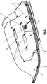
- a roof module according to the invention which comprises a headliner 2, shown here only in part, which covers an interior of a motor vehicle and which is a thermoformed plastic component.
- the roof module further comprises a headliner side part 1, which is arranged outside of the headliner 2 as seen from the vehicle interior when installed, that is to say forming an outer layer, the headliner side part 1 also being a thermoformed plastic component.
- a contact line 12, namely a seal, runs between the headliner 2 and the headliner side part 1, which is shown in FIG Fig. 1 is shown only in sections and which is tightly connected to both the headliner 2 and to the headliner side part 1.
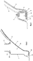
- a gap 15 which is open towards the vehicle interior, runs between the headliner 2 and the headliner side part 1, which into the FIGS. 2 and 3 you can see.
- a channel 16 is thus formed by the contact line 12 or by the seal between the headliner 2 and the headliner side part 1, which in the installed position is open towards the vehicle interior via the gap 15.
- air can therefore be routed between two thermoformed components 1, 2 which form a channel 16, in particular an air channel.
- the channel 16 in particular an air channel, is created between the components. As shown, this channel 16 can only be formed in the outlet area, but can also be used across the course of the two thermoformed parts 1, 2.
- the channel 16 can have the same cross-sectional area with changed lengths / widths over the course of the component 1, 2. Furthermore, both cross-section-widening (diffuser) and cross-section-reducing (nozzle) designs or areas of the channel 16 are possible. A flow-optimized air outlet can thus be formed in the outlet area, that is to say at the gap 15.
- the angle of the inclined surface of the roof lining side part 1 in the outlet area specifies the direction of flow, for example for outflowing air. This allows the air flow and thus the flow towards the side window to be optimized.
- the air can be supplied, for example, through standard air hoses 11 available on the market or specially optimized air hoses.
- a connection piece for a provided air hose 11 can also be implemented on the air hose opening 17 of the roof module.
- a passenger is not directly from the conditioned air blown.
- the air flow can perform a defrost / demist function for the windows all around.
- the width of the area to be flowed into can be specified in a simple manner via the length of the air outlet.
- the components of the roof module can be made from the following materials or by the following processes:
- the roof lining side part 1 as a plastic part, preferably a vacuum-deep-drawn plastic component, in particular a thermoformed part, as well as the roof lining 2, the holder 3 at the top and the holder 4 at the bottom of the roof module.
- the connecting profiles 5, in particular U-profiles, can be extruded aluminum profiles or milled cuts, for example made of plastic, and the clips 7 can be implemented by means of Christmas tree clips.
- the contact line 12 can be implemented, for example, by a liquid sealant or a sealing foam tape.
- the contact line 12, and in particular a sealing contact line 12 can also already be formed by the roof lining side part 1 and / or by the roof lining 2 itself, so that no additional sealing component is required.
- the connections between the components of the roof module can be made in the following way:
- the holder 3 (above) can be preassembled on the roof lining 2, in particular glued by means of adhesive 8 (see FIG Fig. 4 ) or ultrasonic welded.
- the holder 3 (above) can be fastened to a roof lining side part 1 by clips 7, in particular by two clips 7.
- the holder 4 - down in Fig. 1 - is also preassembled on the headliner 2, in particular glued or ultrasonically welded, and fastened to the headliner side part 1, for example, by three clips 7.
- the holder designed as a connecting profile 5, namely as a U-profile, is also preassembled on the headliner 2, in particular glued by means of adhesive 8 (see FIG Fig. 3 ).
- a connecting profile 5 can be fastened to the roof lining side part 1 by means of a clip 7 in each case.
- at least four clips 7 can be provided on a roof lining side part 1.
- An air hose 11 can be fastened in such a way that a connection piece with an air hose 11 attached is screwed to a roof lining side part 1 and is sealed by an inserted air hose seal 18.
- the seal on the contact line 12 between the headliner 2 and the headliner side part 1 is carried out by a preassembled seal.
- a roof module according to the invention can fulfill a lighting function, in particular for ambient lighting of the interior of a motor vehicle.
- the holders which represent connecting profiles 5, can simultaneously form receptacles for light strips 9, in particular LED strips.
- the light strips 9 can include, for example: an aluminum heat sink, an LED strip, optionally a diffuser.
- the U-profiles 5 with the light strips 9 can in turn be preassembled, in particular glued, on the roof lining 2.
- the gap 15 between the roof liner 2 and the roof liner side part 1 results in an all-round uniform light joint for the ambient light.
- the gap 15 is set and defined via the holder or holders with U-profile 5.
- the inclined surface on the roof lining side part 1 opposite the light strip 9 serves as an optical reflection surface 13 for the uniform representation of the ambient lighting.
- the distance and angle between the LED strip 9 and the reflective surface 13 are preferably designed to be the same all around in order to obtain a uniform light result.
- the optional diffuser on the light strip 9 helps avoid undesired hotspots.
Landscapes
- Engineering & Computer Science (AREA)
- Mechanical Engineering (AREA)
- Physics & Mathematics (AREA)
- Thermal Sciences (AREA)
- Vehicle Interior And Exterior Ornaments, Soundproofing, And Insulation (AREA)
Abstract
Description
- Die vorliegende Erfindung betrifft ein Dachmodul für ein Kraftfahrzeug und ein Kraftfahrzeug mit einem solchen Dachmodul.
- Es ist bekannt, dass Dächer für Kraftfahrzeuge einen Dachhimmel umfassen können, der einem Innenraum des Kraftfahrzeugs zugewandt, also an der Innenseite eines Daches ausgebildet sein kann. Derartige Dachhimmel können als thermogeformte Kunststoffbauteile ausgeführt sein. Dachhimmel können mit weiteren Dachteilen, mit Befestigungsteilen und/oder mit Funktionsteilen, wie zum Beispiel Belüftungskanälen oder Beleuchtungselementen, zusammen ein Dachmodul bilden.
- Es ist eine Aufgabe der Erfindung, ein Dachmodul für ein Kraftfahrzeug anzugeben, das die Verwirklichung von Zusatzfunktionen wie Belüftung oder Beleuchtung unterstützt und dabei einfach und kostengünstig hergestellt werden kann. Eine Aufgabe der Erfindung ist es auch ein Kraftfahrzeug mit einem solchen Dachmodul anzugeben, dass für derartige Zusatzfunktionen vorbereitet oder ausgebildet ist.
- Die Lösung der Aufgabe erfolgt durch ein Dachmodul für ein Kraftfahrzeug, umfassend einen Dachhimmel, wobei der Dachhimmel ein thermogeformtes Kunststoffbauteil ist, einen in Einbaulage von einem Fahrzeuginnenraum aus gesehen außerhalb des Dachhimmels angeordneten Dachhimmelseitenteil, wobei der Dachhimmelseitenteil ein thermogeformtes Kunststoffbauteil ist, wobei zwischen dem Dachhimmel und dem Dachhimmelseitenteil eine Kontaktlinie (12) verläuft, wobei die Kontaktlinie durch ein Verbindungsbauteil, insbesondere ein Dichtungsbauteil, ausgebildet ist und/oder wobei die Kontaktlinie durch direkten Kontakt zwischen dem Dachhimmel und dem Dachhimmelseitenteil ausgebildet ist, wobei in Einbaulage fahrzeugrandseitig der Kontaktlinie ein zum Fahrzeuginnenraum hin offener Spalt zwischen Dachhimmel und Dachhimmelseitenteil verläuft, so dass zwischen Dachhimmel und Dachhimmelseitenteil fahrzeugrandseitig der Kontaktlinie ein Kanal gebildet ist, der in Einbaulage zum Fahrzeuginnenraum hin offen ist.
- Erfindungsgemäß ist ein Dachmodul aus zwei Lagen aufgebaut, nämlich einem innen - also näher am Fahrzeuginnenraum - liegenden Dachhimmel und einem, oder bevorzugt zwei, außen - also weiter entfernt vom Fahrzeuginnenraum - liegenden Dachhimmelseitenteilen, wobei ein Dachhimmelseitenteil bevorzugt nur einen Abschnitt des Dachhimmels von außen überdeckt. Der oder die Dachhimmelseitenteile erstrecken sich bevorzugt in Einbaulage in Fahrzeuglängsrichtung entlang einer oder beider Seiten eines Fahrzeuges, also im Wesentlichen oberhalb der Seitenwände und Seitenfenster eines Fahrzeuges.
- Dachhimmel und Dachhimmelseitenteil sind über eine den Dachhimmel mit dem Dachhimmelseitenteil verbindende Kontaktlinie, insbesondere eine Dichtungsleiste, miteinander verbunden, die bevorzugt zumindest abschnittsweise in Längsrichtung des Seitenteils und besonders bevorzugt auch in Längsrichtung des Fahrzeugs angeordnet ist. Die Kontaktlinie verläuft zumindest nicht vollständig in Querrichtung des Seitenteils und des Fahrzeugs. Die Kontaktlinie trennt damit einen fahrzeugrandseitigen Teil des Dachmoduls, der näher der linken oder rechten Außenseite des Kraftfahrzeuges liegt, von einem Teil des Dachmoduls der näher zur Längsmittelachse des Kraftfahrzeugs liegt. Der in Relation zur Kontaktline fahrzeugrandseitige Teil des Dachmoduls, also der von der Fahrzeuglängsmittelachse entferntere Teil, bildet einen Kanal aus, der über einen sich vorzugsweise in Fahrzeuglängsrichtung erstreckenden Spalt mit dem Fahrzeuginnenraum fluidverbunden ist.
- Erfindungsgemäß wird daher durch die Verwendung zweier einfacher thermogeformter Kunststoffbauteile, die abschnittsweise miteinander unmittelbar oder mittelbar verbunden sind, in einem Dachmodul ein Kanal ausgebildet, der über einen Spalt mit dem Fahrzeug-Innenraum verbunden ist, so dass über den Spalt zwischen Dachhimmel und Dachhimmelseitenteil auf einfache und effiziente Weise beispielsweise Luft oder Licht in den Innenraum des Kraftfahrzeugs zuführbar ist.
- Vorzugsweise verläuft der Spalt zwischen Dachhimmel und Dachhimmelseitenteil in einer Längsrichtung des Dachhimmelseitenteils. Besonders bevorzugt verläuft der Spalt in Einbaulage in einer Längsrichtung des Kraftfahrzeuges. Bevorzugt verläuft auch die Kontaktlinie zumindest abschnittsweise in der Längsrichtung des Dachhimmelseitenteils.
- Vorzugsweise ist der Dachhimmel über mehrere Clips mit dem Dachhimmelseitenteil verclipst. Bevorzugt ist der Dachhimmel mit dem Dachhimmelseitenteil ausschließlich verclipst und nicht verklebt.
- Bevorzugt bildet der Dachhimmelseitenteil auf seiner dem Dachhimmel zugewandten Seite abschnittsweise eine Reflexionsfläche aus, die dem Spalt benachbart ist und die mit dem Spalt einen Winkel kleiner 90 Grad bildet. Die Reflexionsfläche kann also genutzt werden um beispielsweise Licht oder Luft aus dem Kanal in den Spalt umzulenken. Bevorzugt wird die Richtung des eintreffenden Mediums, insbesondere Licht oder Luft, von der Reflexionsfläche um ca. 90 Grad umgelenkt.
- An der Reflexionsfläche ist bevorzugt ein optisch reflektierendes Element oder eine optisch reflektierende Beschichtung angeordnet.
- Das Dachmodul umfasst vorzugsweise einen Leuchtstreifen, wobei der Leuchtstreifen so angeordnet ist, dass das Licht des Leuchtstreifens über die Reflexionsfläche durch den Spalt geleitet wird.
- Bevorzugt umfasst das Dachmodul zumindest einen Halter, wobei der Halter vorzugsweise ein thermogeformtes Kunststoffbauteil ist, wobei der Halter eine in Längsrichtung des Dachhimmelseitenteils verlaufende Leiste bildet, wobei an der in Einbaulage dem Fahrzeuginnenraum zugewandten Seite des Halters der Dachhimmel am Halter befestigt ist und an der in Einbaulage vom Fahrzeuginnenraum abgewandten Seite des Halters der Dachhimmelseitenteil am Halter befestigt ist.
- Der Dachhimmel ist bevorzugt stoffschlüssig am Halter befestigt und der Dachhimmelseitenteil ist bevorzugt über mehrere Clips mit dem Halter verclipst.
- Bevorzugt umfasst das Dachmodul zumindest ein Verbindungsprofil, wobei das Verbindungsprofil eine Verbindung zwischen dem Dachhimmel und dem Dachhimmelseitenteil bildet, wobei bevorzugt das Verbindungsprofil zumindest abschnittsweise die Kontaktlinie zwischen dem Dachhimmel und dem Dachhimmelseitenteil bildet und somit ein Verbindungsbauteil zwischen Dachhimmel und Dachhimmelseitenteil darstellt.
- Auf dem Verbindungsprofil kann eine Leuchte, insbesondere ein Leuchtstreifen, befestigt sein.
- Das Verbindungsprofil ist vorzugsweise ein U-Profil, wobei an einem in Einbaulage dem Fahrzeuginnenraum zugewandten Schenkel des U-Profils der Dachhimmel am U-Profil befestigt ist und an einem in Einbaulage vom Fahrzeuginnenraum abgewandten Schenkel des U-Profils der Dachhimmelseitenteil am U-Profil befestigt ist.
- Bevorzugt ist der Dachhimmel stoffschlüssig am U-Profil befestigt und der Dachhimmelseitenteil ist bevorzugt über zumindest einen Clip mit dem U-Profil verclipst.
- Der in Einbaulage dem Fahrzeuginnenraum zugewandte Schenkel des U-Profils ist bevorzugt in der Nähe des Spalts zwischen Dachhimmel und Dachhimmelseitenteil angeordnet, wobei die offene Seite der U-Form des U-Profils auf derjenigen Seite des Dachhimmels liegt, die dem Spalt zugewandt ist.
- Auf dem Boden des U-Profils ist vorzugsweise der Leuchtstreifen befestigt.
- Das Verbindungsprofil bzw. das U-Profil muss kein durchgängiges Bauteil sein, dass gleich lang ausgestaltet ist wie ein daran befestigter Leuchtstreifen, beispielsweise LED-Streifen, sondern es können mehrere separate Bauteile sein, an denen ein sich in der Länge erstreckender Leuchtstreifen jeweils befestigt ist.
- Bevorzugt umfasst das Dachmodul einen Luftschlauch, wobei der Luftschlauch mit einer Öffnung des Dachhimmelseitenteils fluidverbunden ist, so dass über den Luftschlauch dem Kanal Luft zugeführt werden kann.
- Die über den Luftschlauch zugeführte Luft, kann dann über den Kanal in den Fahrzeuginnenraum gelangen, insbesondere im Bereich von Seitenfenstern des Kraftfahrzeuges. Für die Luftzuführung werden bevorzugt keine Luftauslassdüsen und keine Lüftungsschlitzabdeckungen verwendet. Vielmehr erfolgt die Luftzuführung einfach durch den Spalt zwischen Dachhimmel und Dachhimmelseitenteil. Dachhimmel und Dachhimmelseitenteil bilden somit zusammen den Luftzuführungskanal in den Fahrzeuginnenraum aus.
- Ein Kraftfahrzeug kann erfindungsgemäß ein Dachmodul wie oben beschrieben umfassen. Dabei ist der Dachhimmel dem Fahrzeuginnenraum zugewandt, bildet also eine innere Schicht des Daches. Der Dachhimmelseitenteil ist vom Fahrzeuginnenraum abgewandt, bildet also eine äußere Schicht des Daches. Fahrzeugrandseitig der Kontaktlinie, also jeweils von der Fahrzeuglängsmittelachse aus gesehen außen, verläuft ein Spalt zwischen Dachhimmel und Dachhimmelseitenteil in der Längsrichtung des Dachhimmelseitenteils, so dass zwischen Dachhimmel und Dachhimmelseitenteil ein Kanal gebildet ist, der in der Längsrichtung des Dachhimmelseitenteils verläuft und der zum Fahrzeuginnenraum hin offen ist.
- Die Erfindung wird im Folgenden beispielhaft unter Bezugnahme auf die Zeichnungen beschrieben.
- Fig. 1
- ist eine dreidimensionale Teildarstellung eines erfindungsgemäßen Dachmoduls im Bereich eines Dachhimmelseitenteils .
- Fig. 2
- ist eine Schnittansicht des Dachmoduls gemäß
Fig. 1 im Bereich der Luftschlauchöffnung mit angeschlossenem Luftschlauch. - Fig. 3
- ist eine Schnittansicht des Dachmoduls gemäß
Fig. 1 im Bereich eines U-Profils. - Fig. 4
- ist eine Schnittansicht des Dachmoduls gemäß
Fig. 1 im Bereich des oberen oder unteren Halters. - In
Fig. 1 ist ein erfindungsgemäßes Dachmodul dargestellt, welches einen, hier nur ausschnittsweise dargestellten, Dachhimmel 2 umfasst, der einen Innenraum eines Kraftfahrzeuges überdeckt und der ein thermogeformtes Kunststoffbauteil ist. Das Dachmodul umfasst ferner einen in Einbaulage vom Fahrzeuginnenraum aus gesehen außerhalb des Dachhimmels 2 angeordneten, also eine äußere Schicht bildenden Dachhimmelseitenteil 1, wobei der Dachhimmelseitenteil 1 ebenfalls ein thermogeformtes Kunststoffbauteil ist. Zwischen dem Dachhimmel 2 und dem Dachhimmelseitenteil 1 verläuft eine Kontaktlinie 12, nämlich eine Dichtung, die inFig. 1 nur abschnittsweise dargestellt ist und die sowohl mit dem Dachhimmel 2 als auch mit dem Dachhimmelseitenteil 1 dicht verbunden ist. Fahrzeugrandseitig der Kontaktlinie 12, also in Richtung des äußeren Randes des Dachhimmels 2, verläuft ein zum Fahrzeuginnenraum hin offener Spalt 15 zwischen Dachhimmel 2 und Dachhimmelseitenteil 1, der in denFig. 2 und Fig. 3 zu sehen ist. Es wird somit durch die Kontaktlinie 12 bzw. durch die Dichtung zwischen Dachhimmel 2 und Dachhimmelseitenteil 1 ein Kanal 16 gebildet, der in Einbaulage zum Fahrzeuginnenraum hin über den Spalt 15 offen ist. - Erfindungsgemäß kann daher eine Luftführung zwischen zwei thermogeformten Bauteilen 1, 2 erfolgen, die einen Kanal 16, insbesondere einen Luftkanal bilden.
- Durch das Verclipsen des Dachhimmels 2 mit dem Dachhimmelseitenteil 1 und dem damit verbundenen Verpressen der Dichtung an der Kontaktlinie 12 entsteht zwischen den Bauteilen der Kanal 16, insbesondere Luftkanal. Dieser Kanal 16 kann, wie dargestellt, nur im Auslassbereich ausgebildet sein, aber auch quer über den Verlauf der beiden thermogeformten Teile 1, 2 genutzt werden.
- Der Kanal 16 kann eine gleiche Querschnittsfläche bei veränderten Längen/Breiten über den Bauteilverlauf 1, 2 aufweisen. Ferner sind sowohl querschnitterweiternde- (Diffusor) als auch querschnittsveringernde (Düse) Ausführungen oder Bereiche des Kanals 16 möglich. Somit kann im Auslassbereich, also am Spalt 15, ein strömungstechnisch optimierter Luftauslass ausgebildet werden.
- Der Winkel der angestellten Fläche des Dachhimmelseitenteils 1 im Auslassbereich, also der Reflexionsfläche 13, gibt die Strömungsrichtung beispielsweise für ausströmende Luft, vor. Damit kann der Luftverlauf und somit die Strömung Richtung Seitenscheibe optimiert werden.
Die Luftzufuhr kann beispielsweise durch am Markt erhältliche Standard-Luftschläuche 11 oder speziell optimierte Luftschläuche erfolgen. An der Luftschlauchöffnung 17 des Dachmoduls kann auch ein Anschlussstück für einen vorgesehenen Luftschlauch 11 ausgeführt sein. - Durch eine Luftzufuhr über ein erfindungsgemäßes Dachmodul können mehre Vorteile erreicht werden. Ein Passagier wird nicht direkt von der konditionierten Luft angeblasen. Der Luftstrom kann eine Defrost/Demist-Funktion für die Scheiben rundum erfüllen. Über die Länge des Luftauslasses kann die Breite des anzuströmenden Bereiches auf einfache Weise vorgegeben werden.
- Die Bauteile des Dachmoduls können aus folgenden Materialien bzw. durch folgende Verfahren hergestellt sein: Das Dachhimmelseitenteil 1 als Kunststoffteil, vorzugsweise vakuumtiefgezogenes Kunststoffbauteil insbesondere Thermoformteil, ebenso der Dachhimmel 2, der Halter 3 oben und der Halter 4 unten am Dachmodul.
- Die Verbindungsprofile 5, insbesondere U-Profile, können Aluminium Strangpressprofile oder Fräsbeschnitte sein, beispielsweise aus Kunststoff, die Clips 7 können durch Tannenbaumclips realisiert sein. Die Kontaktlinie 12 kann beispielsweise durch ein flüssiges Dichtmittel oder ein Dichtschaumband realisiert sein. Die Kontaktlinie 12, und insbesondere eine dichtende Kontaktlinie 12, kann auch bereits durch das Dachhimmelseitenteil 1 und/oder durch den Dachhimmel 2 selbst ausgebildet sein, sodass kein zusätzliches Dichtungsbauteil erforderlich ist.
- Die Verbindungen der Bauteile des Dachmoduls können auf folgende Weise hergestellt sein: Der Halter 3 (oben) kann auf dem Dachhimmel 2 vormontiert sein, insbesondere geklebt mittels Klebstoff 8 (siehe
Fig. 4 ) oder Ultraschall-geschweißt. Durch Clips 7, insbesondere durch zwei Clips 7, kann der Halter 3 (oben) an einem Dachhimmelseitenteil 1 befestigt sein. - Der Halter 4 - unten in
Fig. 1 - ist ebenfalls auf dem Dachhimmel 2 vormontiert, insbesondere geklebt, oder Ultraschall-geschweißt, und beispielsweise durch drei Clips 7 am Dachhimmelseitenteil 1 befestigt. - Der als Verbindungsprofil 5, nämlich als U-Profil ausgeführte Halter ist ebenso am Dachhimmel 2 vormontiert, insbesondere mittels Klebstoff 8 geklebt (siehe
Fig. 3 ). Ein Verbindungsprofil 5 kann durch jeweils einen Clip 7 am Dachhimmelseitenteil 1 befestigt sein. Es können beispielsweise mindestens vier Clips 7 an einem Dachhimmelseitenteil 1 vorgesehen sein. - Die Befestigung eines Luftschlauches 11 kann so erfolgen, dass ein Anschlussstück mit aufgestecktem Luftschlauch 11 mit einem Dachhimmelseitenteil 1 verschraubt wird und durch eine eingelegte Luftschlauchdichtung 18 gedichtet wird.
- Die Abdichtung an der Kontaktlinie 12 zwischen Dachhimmel 2 und Dachhimmelseitenteil 1 erfolgt durch eine vormontierte Dichtung.
- Zusätzlich oder alternativ zu einer Belüftungsfunktion kann ein erfindungsgemäßes Dachmodul eine Beleuchtungsfunktion erfüllen, insbesondere für eine Ambiente-Beleuchtung des Innenraums eines Kraftfahrzeuges.
- Die Halter, die Verbindungsprofile 5 darstellen, können gleichzeitig Aufnahmen für Leuchtstreifen 9, insbesondere LED-Streifen, bilden. Die Leuchtstreifen 9 können beispielsweise umfassen: einen Aluminium-Kühlkörper, einen LED-Streifen, optional eine Streuscheibe. Die U-Profile 5 mit den Leuchtstreifen 9 können wiederum vormontiert, insbesondere geklebt, sein auf dem Dachhimmel 2.
- Der Spalt 15 zwischen Dachhimmel 2 und Dachhimmelseitenteil 1 ergibt eine rundum gleichmäßige Lichtfuge für das Ambiente Licht. Der Spalt 15 wird über den bzw. die Halter mit U-Profil 5 eingestellt und definiert.
- Die schräge Fläche am Dachhimmelseitenteil 1 gegenüber dem Leuchtstreifen 9 dient als optische Reflexionsfläche 13 zur gleichmäßigen Darstellung der Ambiente Beleuchtung. Der Abstand und Winkel zwischen LED-Streifen 9 und Reflexionsfläche 13 sind vorzugsweise rundum gleich ausgeführt, um ein gleichmäßiges Lichtergebnis zu erhalten. Die optionale Streuscheibe am Leuchtstreifen 9 unterstützt die Vermeidung von unerwünschten Hotspots.
-
- 1
- Dachhimmelseitenteil
- 2
- Dachhimmel
- 3
- (oberer) Halter
- 4
- (unterer) Halter
- 5
- Verbindungsprofil
- 7
- Clips
- 8
- Klebstoff
- 9
- Leuchtstreifen
- 11
- Luftschlauch
- 12
- Kontaktlinie
- 13
- Reflexionsfläche
- 15
- Spalt
- 16
- Kanal
- 17
- Luftschlauchöffnung
- 18
- Luftschlauchdichtung
Claims (16)
- Dachmodul für ein Kraftfahrzeug, umfassend einen Dachhimmel (2), wobei der Dachhimmel (2) ein thermogeformtes Kunststoffbauteil ist, einen in Einbaulage von einem Fahrzeuginnenraum aus gesehen außerhalb des Dachhimmels (2) angeordneten Dachhimmelseitenteil (1), wobei der Dachhimmelseitenteil (1) ein thermogeformtes Kunststoffbauteil ist, wobei zwischen dem Dachhimmel (2) und dem Dachhimmelseitenteil (1) eine Kontaktlinie (12) verläuft, wobei die Kontaktlinie (12) durch ein Verbindungsbauteil, insbesondere ein Dichtungsbauteil, ausgebildet ist und/oder wobei die Kontaktlinie (12) durch direkten Kontakt zwischen dem Dachhimmel (2) und dem Dachhimmelseitenteil (1) ausgebildet ist, wobei in Einbaulage fahrzeugrandseitig der Kontaktlinie (12) ein zum Fahrzeuginnenraum hin offener Spalt (15) zwischen Dachhimmel (2) und Dachhimmelseitenteil (1) verläuft, so dass zwischen Dachhimmel (2) und Dachhimmelseitenteil (1) fahrzeugrandseitig der Kontaktlinie (12) ein Kanal (16) gebildet ist, der in Einbaulage zum Fahrzeuginnenraum hin offen ist.
- Dachmodul nach Anspruch 1,
dadurch gekennzeichnet, dass der Spalt (15) zwischen Dachhimmel (2) und Dachhimmelseitenteil (1) in einer Längsrichtung des Dachhimmelseitenteils (1) und/oder in Einbaulage in einer Längsrichtung des Kraftfahrzeuges verläuft. - Dachmodul nach zumindest einem der vorhergehenden Ansprüche,
dadurch gekennzeichnet, dass der Dachhimmel (2) über mehrere Clips (7) mit dem Dachhimmelseitenteil (1) verclipst ist. - Dachmodul nach zumindest einem der vorhergehenden Ansprüche,
dadurch gekennzeichnet, dass der Dachhimmelseitenteil (1) auf seiner dem Dachhimmel (2) zugewandten Seite abschnittsweise eine Reflexionsfläche (13) ausbildet, die dem Spalt (15) benachbart ist und die mit dem Spalt (15) einen Winkel kleiner 90 Grad bildet. - Dachmodul nach Anspruch 4,
dadurch gekennzeichnet, dass an der Reflexionsfläche (13) ein optisch reflektierendes Element oder eine optisch reflektierende Beschichtung angeordnet ist. - Dachmodul nach Anspruch 4 oder 5,
dadurch gekennzeichnet, dass das Dachmodul einen Leuchtstreifen (9) umfasst, wobei der Leuchtstreifen (9) so angeordnet ist, dass das Licht des Leuchtstreifens (9) über die Reflexionsfläche (13) durch den Spalt (15) geleitet wird. - Dachmodul nach zumindest einem der vorhergehenden Ansprüche,
dadurch gekennzeichnet, dass das Dachmodul zumindest einen Halter (3, 4) umfasst, wobei der Halter (3, 4) eine in Längsrichtung des Dachhimmelseitenteils (1) verlaufende Leiste bildet, wobei an der in Einbaulage dem Fahrzeuginnenraum zugewandten Seite des Halters (3, 4) der Dachhimmel (2) am Halter (3, 4) befestigt ist und an der in Einbaulage vom Fahrzeuginnenraum abgewandten Seite des Halters (3, 4) der Dachhimmelseitenteil (1) am Halter (3, 4) befestigt ist, wobei der Halter (3, 4) vorzugsweise ein thermogeformtes Kunststoffbauteil ist. - Dachmodul nach Anspruch 7,
dadurch gekennzeichnet, dass der Dachhimmel (2) stoffschlüssig am Halter (3, 4) befestigt ist und der Dachhimmelseitenteil (1) über mehrere Clips (7) mit dem Halter (3, 4) verclipst ist. - Dachmodul nach zumindest einem der vorhergehenden Ansprüche,
dadurch gekennzeichnet, dass das Dachmodul zumindest ein Verbindungsprofil (5) umfasst, wobei das Verbindungsprofil (5) eine Verbindung zwischen dem Dachhimmel (2) und dem Dachhimmelseitenteil (1) bildet, wobei bevorzugt das Verbindungsprofil (5) zumindest abschnittsweise die Kontaktlinie (12) zwischen dem Dachhimmel (2) und dem Dachhimmelseitenteil (1) bildet. - Dachmodul nach Anspruch 9,
dadurch gekennzeichnet, dass eine Leuchte, insbesondere ein Leuchtstreifen (9), auf dem Verbindungsprofil (5) befestigt ist. - Dachmodul nach zumindest einem der vorhergehenden Ansprüche 9 bis 10,
dadurch gekennzeichnet, dass das Verbindungsprofil (5) durch ein U-Profil gebildet wird, wobei an einem in Einbaulage dem Fahrzeuginnenraum zugewandten Schenkel des U-Profils der Dachhimmel (2) am U-Profil befestigt ist und an einem in Einbaulage vom Fahrzeuginnenraum abgewandten Schenkel des U-Profils der Dachhimmelseitenteil (1) am U-Profil befestigt ist. - Dachmodul nach Anspruch 11,
dadurch gekennzeichnet, dass der Dachhimmel (2) stoffschlüssig am U-Profil befestigt ist und der Dachhimmelseitenteil (1) über zumindest einen Clip (7) mit dem U-Profil verclipst ist. - Dachmodul nach Anspruch 11 oder 12,
dadurch gekennzeichnet, dass der in Einbaulage dem Fahrzeuginnenraum zugewandte Schenkel des U-Profils in der Nähe des Spalts (15) zwischen Dachhimmel (2) und Dachhimmelseitenteil (1) angeordnet ist, wobei die offene Seite der U-Form des U-Profils auf derjenigen Seite des Dachhimmels (2) liegt, die dem Spalt (15) zugewandt ist. - Dachmodul nach Anspruch 6 und nach einem der Ansprüche 9 bis 11,
dadurch gekennzeichnet, dass auf dem Boden des U-Profils der Leuchtstreifen (9) befestigt ist. - Dachmodul nach zumindest einem der vorhergehenden Ansprüche,
dadurch gekennzeichnet, dass das Dachmodul einen Luftschlauch (11) umfasst, wobei der Luftschlauch (11) mit einer Luftschlauchöffnung (17) des Dachhimmelseitenteils (1) fluidverbunden ist, so dass über den Luftschlauch (11) dem Kanal (16) Luft zugeführt werden kann. - Kraftfahrzeug umfassend ein Dachmodul nach zumindest einem der vorhergehenden Ansprüche,
dadurch gekennzeichnet, dass der Dachhimmel (2) dem Fahrzeuginnenraum zugewandt ist, dass der Dachhimmelseitenteil (1) vom Fahrzeuginnenraum abgewandt ist, wobei fahrzeugrandseitig der Kontaktlinie(12) ein Spalt (15) zwischen Dachhimmel (2) und Dachhimmelseitenteil (1) in der Längsrichtung des Dachhimmelseitenteils (1) verläuft, so dass zwischen Dachhimmel (2) und Dachhimmelseitenteil (1) ein Kanal (16) gebildet ist, der in der Längsrichtung des Dachhimmelseitenteils (1) verläuft und der zum Fahrzeuginnenraum hin offen ist.
Priority Applications (1)
| Application Number | Priority Date | Filing Date | Title |
|---|---|---|---|
| EP19204590.4A EP3812217B1 (de) | 2019-10-22 | 2019-10-22 | Dachmodul |
Applications Claiming Priority (1)
| Application Number | Priority Date | Filing Date | Title |
|---|---|---|---|
| EP19204590.4A EP3812217B1 (de) | 2019-10-22 | 2019-10-22 | Dachmodul |
Publications (2)
| Publication Number | Publication Date |
|---|---|
| EP3812217A1 true EP3812217A1 (de) | 2021-04-28 |
| EP3812217B1 EP3812217B1 (de) | 2022-12-28 |
Family
ID=68342495
Family Applications (1)
| Application Number | Title | Priority Date | Filing Date |
|---|---|---|---|
| EP19204590.4A Active EP3812217B1 (de) | 2019-10-22 | 2019-10-22 | Dachmodul |
Country Status (1)
| Country | Link |
|---|---|
| EP (1) | EP3812217B1 (de) |
Citations (6)
| Publication number | Priority date | Publication date | Assignee | Title |
|---|---|---|---|---|
| WO1999048712A1 (en) * | 1998-03-20 | 1999-09-30 | Lear Automotive Dearborn, Inc. | Plastic air duct integrated to headliner |
| EP1223082A2 (de) * | 2001-01-15 | 2002-07-17 | ArvinMeritor GmbH | Fahrzeugdach, inbesondere Kraftfahrzeugdachmodul |
| EP1302369A2 (de) * | 2001-10-16 | 2003-04-16 | HAPPICH Fahrzeug- und Industrieteile GmbH | Roof liner and air duct system |
| GB2389825A (en) * | 2002-06-21 | 2003-12-24 | Lear Corp | Vehicle headliner with blow moulded air duct |
| DE10362300B4 (de) * | 2003-11-18 | 2013-06-20 | Volkswagen Ag | Belüftungseinrichtung für einen Fahrzeuginnenraum eines Fahrzeuges, insbesondere eines Nutzfahrzeuges |
| DE102012003497A1 (de) * | 2012-02-22 | 2013-08-22 | Volkswagen Aktiengesellschaft | Dachinnenverkleidung eines Kraftfahrzeugs |
-
2019
- 2019-10-22 EP EP19204590.4A patent/EP3812217B1/de active Active
Patent Citations (6)
| Publication number | Priority date | Publication date | Assignee | Title |
|---|---|---|---|---|
| WO1999048712A1 (en) * | 1998-03-20 | 1999-09-30 | Lear Automotive Dearborn, Inc. | Plastic air duct integrated to headliner |
| EP1223082A2 (de) * | 2001-01-15 | 2002-07-17 | ArvinMeritor GmbH | Fahrzeugdach, inbesondere Kraftfahrzeugdachmodul |
| EP1302369A2 (de) * | 2001-10-16 | 2003-04-16 | HAPPICH Fahrzeug- und Industrieteile GmbH | Roof liner and air duct system |
| GB2389825A (en) * | 2002-06-21 | 2003-12-24 | Lear Corp | Vehicle headliner with blow moulded air duct |
| DE10362300B4 (de) * | 2003-11-18 | 2013-06-20 | Volkswagen Ag | Belüftungseinrichtung für einen Fahrzeuginnenraum eines Fahrzeuges, insbesondere eines Nutzfahrzeuges |
| DE102012003497A1 (de) * | 2012-02-22 | 2013-08-22 | Volkswagen Aktiengesellschaft | Dachinnenverkleidung eines Kraftfahrzeugs |
Also Published As
| Publication number | Publication date |
|---|---|
| EP3812217B1 (de) | 2022-12-28 |
Similar Documents
| Publication | Publication Date | Title |
|---|---|---|
| DE19632620C1 (de) | Außenrückspiegel für ein Kraftfahrzeug | |
| EP3103665B1 (de) | Profilleiste, system und verfahren zur herstellung einer profilleiste | |
| DE102005031875B4 (de) | Dachmodul mit Belüftungskanal | |
| DE3733229C2 (de) | Fahrzeugfenster mit einer verschiebbaren Doppelscheibe, insbesondere für Autotüren | |
| DE102013218559B4 (de) | Säulenstruktur für Fahrzeug | |
| DE112013003819B4 (de) | Fahrzeugseitenentfrosteraufbau | |
| EP2998144A1 (de) | Fahrzeug mit dichtungsprofil | |
| EP3812217B1 (de) | Dachmodul | |
| DE4340999A1 (de) | Gassack-Aufprall-Schutzeinrichtungen für Kraftfahrzeuge | |
| DE19743107C2 (de) | Außenspiegel für Fahrzeuge | |
| DE102021131727A1 (de) | Fahrzeugscheibenanordnung | |
| DE202013000888U1 (de) | Vorrichtung zur Abdeckung eines in Längsrichtung eines Kraftfahrzeuges verlaufenden Dachkanals | |
| DE102014203175A1 (de) | Kraftfahrzeug | |
| DE102013012628A1 (de) | Wasserführungslippe | |
| EP1522437B1 (de) | Luftversorgungseinrichtung zur Klimatisierung eines Fahrzeuginnenraums eines Fahrzeugs, insbesondere eines Nutzfahrzeuges | |
| DE4434054C2 (de) | Verglasung | |
| EP0523373B1 (de) | Fahrgastraumheizung für ein Kraftfahrzeug, insbesondere für einen Omnibus | |
| DE102015016790A1 (de) | Türverkleidungsanordnung sowie Verwendung einer Türverkleidungsanordnung | |
| DE2837063A1 (de) | Anordnung aus profilschiene und seitenabdeckung fuer ein passagierfahrzeug | |
| WO2022258347A1 (de) | Dach für einen kraftwagen, insbesondere für einen personenkraftwagen, sowie kraftwagen | |
| DE19534290C2 (de) | Verbindung zwischen einem Strangpreßprofil und einem daran angeschlossenen flächigen Bauteil an einer Fahrzeugkarosserie | |
| DE102006040383B4 (de) | Vorrichtung zum Ableiten von Regenwasser oder dergleichen an einem Luft- oder Raumfahrzeug und ein entsprechendes Fahrzeug | |
| DE102009054009A1 (de) | Anordnung einer Sende- und/oder Empfangseinheit an einem Dachverkleidungsteil eines Kraftwagens | |
| EP1394459B1 (de) | Bauteilverbindung | |
| DE102016215461A1 (de) | Glasdeckeleinheit für ein Dachsystem eines Kraftfahrzeugs |
Legal Events
| Date | Code | Title | Description |
|---|---|---|---|
| PUAI | Public reference made under article 153(3) epc to a published international application that has entered the european phase |
Free format text: ORIGINAL CODE: 0009012 |
|
| STAA | Information on the status of an ep patent application or granted ep patent |
Free format text: STATUS: REQUEST FOR EXAMINATION WAS MADE |
|
| 17P | Request for examination filed |
Effective date: 20201216 |
|
| AK | Designated contracting states |
Kind code of ref document: A1 Designated state(s): AL AT BE BG CH CY CZ DE DK EE ES FI FR GB GR HR HU IE IS IT LI LT LU LV MC MK MT NL NO PL PT RO RS SE SI SK SM TR |
|
| AX | Request for extension of the european patent |
Extension state: BA ME |
|
| STAA | Information on the status of an ep patent application or granted ep patent |
Free format text: STATUS: EXAMINATION IS IN PROGRESS |
|
| 17Q | First examination report despatched |
Effective date: 20210916 |
|
| GRAP | Despatch of communication of intention to grant a patent |
Free format text: ORIGINAL CODE: EPIDOSNIGR1 |
|
| STAA | Information on the status of an ep patent application or granted ep patent |
Free format text: STATUS: GRANT OF PATENT IS INTENDED |
|
| INTG | Intention to grant announced |
Effective date: 20220826 |
|
| GRAS | Grant fee paid |
Free format text: ORIGINAL CODE: EPIDOSNIGR3 |
|
| RAP3 | Party data changed (applicant data changed or rights of an application transferred) |
Owner name: MAGNA STEYR FAHRZEUGTECHNIK GMBH & CO KG |
|
| GRAA | (expected) grant |
Free format text: ORIGINAL CODE: 0009210 |
|
| STAA | Information on the status of an ep patent application or granted ep patent |
Free format text: STATUS: THE PATENT HAS BEEN GRANTED |
|
| AK | Designated contracting states |
Kind code of ref document: B1 Designated state(s): AL AT BE BG CH CY CZ DE DK EE ES FI FR GB GR HR HU IE IS IT LI LT LU LV MC MK MT NL NO PL PT RO RS SE SI SK SM TR |
|
| REG | Reference to a national code |
Ref country code: GB Ref legal event code: FG4D Free format text: NOT ENGLISH |
|
| REG | Reference to a national code |
Ref country code: CH Ref legal event code: EP |
|
| REG | Reference to a national code |
Ref country code: DE Ref legal event code: R096 Ref document number: 502019006623 Country of ref document: DE |
|
| REG | Reference to a national code |
Ref country code: AT Ref legal event code: REF Ref document number: 1540282 Country of ref document: AT Kind code of ref document: T Effective date: 20230115 |
|
| REG | Reference to a national code |
Ref country code: IE Ref legal event code: FG4D Free format text: LANGUAGE OF EP DOCUMENT: GERMAN |
|
| REG | Reference to a national code |
Ref country code: LT Ref legal event code: MG9D |
|
| PG25 | Lapsed in a contracting state [announced via postgrant information from national office to epo] |
Ref country code: SE Free format text: LAPSE BECAUSE OF FAILURE TO SUBMIT A TRANSLATION OF THE DESCRIPTION OR TO PAY THE FEE WITHIN THE PRESCRIBED TIME-LIMIT Effective date: 20221228 Ref country code: NO Free format text: LAPSE BECAUSE OF FAILURE TO SUBMIT A TRANSLATION OF THE DESCRIPTION OR TO PAY THE FEE WITHIN THE PRESCRIBED TIME-LIMIT Effective date: 20230328 Ref country code: LT Free format text: LAPSE BECAUSE OF FAILURE TO SUBMIT A TRANSLATION OF THE DESCRIPTION OR TO PAY THE FEE WITHIN THE PRESCRIBED TIME-LIMIT Effective date: 20221228 Ref country code: FI Free format text: LAPSE BECAUSE OF FAILURE TO SUBMIT A TRANSLATION OF THE DESCRIPTION OR TO PAY THE FEE WITHIN THE PRESCRIBED TIME-LIMIT Effective date: 20221228 |
|
| REG | Reference to a national code |
Ref country code: NL Ref legal event code: MP Effective date: 20221228 |
|
| PG25 | Lapsed in a contracting state [announced via postgrant information from national office to epo] |
Ref country code: RS Free format text: LAPSE BECAUSE OF FAILURE TO SUBMIT A TRANSLATION OF THE DESCRIPTION OR TO PAY THE FEE WITHIN THE PRESCRIBED TIME-LIMIT Effective date: 20221228 Ref country code: LV Free format text: LAPSE BECAUSE OF FAILURE TO SUBMIT A TRANSLATION OF THE DESCRIPTION OR TO PAY THE FEE WITHIN THE PRESCRIBED TIME-LIMIT Effective date: 20221228 Ref country code: HR Free format text: LAPSE BECAUSE OF FAILURE TO SUBMIT A TRANSLATION OF THE DESCRIPTION OR TO PAY THE FEE WITHIN THE PRESCRIBED TIME-LIMIT Effective date: 20221228 Ref country code: GR Free format text: LAPSE BECAUSE OF FAILURE TO SUBMIT A TRANSLATION OF THE DESCRIPTION OR TO PAY THE FEE WITHIN THE PRESCRIBED TIME-LIMIT Effective date: 20230329 |
|
| PG25 | Lapsed in a contracting state [announced via postgrant information from national office to epo] |
Ref country code: NL Free format text: LAPSE BECAUSE OF FAILURE TO SUBMIT A TRANSLATION OF THE DESCRIPTION OR TO PAY THE FEE WITHIN THE PRESCRIBED TIME-LIMIT Effective date: 20221228 |
|
| PG25 | Lapsed in a contracting state [announced via postgrant information from national office to epo] |
Ref country code: SM Free format text: LAPSE BECAUSE OF FAILURE TO SUBMIT A TRANSLATION OF THE DESCRIPTION OR TO PAY THE FEE WITHIN THE PRESCRIBED TIME-LIMIT Effective date: 20221228 Ref country code: RO Free format text: LAPSE BECAUSE OF FAILURE TO SUBMIT A TRANSLATION OF THE DESCRIPTION OR TO PAY THE FEE WITHIN THE PRESCRIBED TIME-LIMIT Effective date: 20221228 Ref country code: PT Free format text: LAPSE BECAUSE OF FAILURE TO SUBMIT A TRANSLATION OF THE DESCRIPTION OR TO PAY THE FEE WITHIN THE PRESCRIBED TIME-LIMIT Effective date: 20230428 Ref country code: ES Free format text: LAPSE BECAUSE OF FAILURE TO SUBMIT A TRANSLATION OF THE DESCRIPTION OR TO PAY THE FEE WITHIN THE PRESCRIBED TIME-LIMIT Effective date: 20221228 Ref country code: EE Free format text: LAPSE BECAUSE OF FAILURE TO SUBMIT A TRANSLATION OF THE DESCRIPTION OR TO PAY THE FEE WITHIN THE PRESCRIBED TIME-LIMIT Effective date: 20221228 Ref country code: CZ Free format text: LAPSE BECAUSE OF FAILURE TO SUBMIT A TRANSLATION OF THE DESCRIPTION OR TO PAY THE FEE WITHIN THE PRESCRIBED TIME-LIMIT Effective date: 20221228 |
|
| PG25 | Lapsed in a contracting state [announced via postgrant information from national office to epo] |
Ref country code: SK Free format text: LAPSE BECAUSE OF FAILURE TO SUBMIT A TRANSLATION OF THE DESCRIPTION OR TO PAY THE FEE WITHIN THE PRESCRIBED TIME-LIMIT Effective date: 20221228 Ref country code: PL Free format text: LAPSE BECAUSE OF FAILURE TO SUBMIT A TRANSLATION OF THE DESCRIPTION OR TO PAY THE FEE WITHIN THE PRESCRIBED TIME-LIMIT Effective date: 20221228 Ref country code: IS Free format text: LAPSE BECAUSE OF FAILURE TO SUBMIT A TRANSLATION OF THE DESCRIPTION OR TO PAY THE FEE WITHIN THE PRESCRIBED TIME-LIMIT Effective date: 20230428 Ref country code: AL Free format text: LAPSE BECAUSE OF FAILURE TO SUBMIT A TRANSLATION OF THE DESCRIPTION OR TO PAY THE FEE WITHIN THE PRESCRIBED TIME-LIMIT Effective date: 20221228 |
|
| REG | Reference to a national code |
Ref country code: DE Ref legal event code: R097 Ref document number: 502019006623 Country of ref document: DE |
|
| PG25 | Lapsed in a contracting state [announced via postgrant information from national office to epo] |
Ref country code: DK Free format text: LAPSE BECAUSE OF FAILURE TO SUBMIT A TRANSLATION OF THE DESCRIPTION OR TO PAY THE FEE WITHIN THE PRESCRIBED TIME-LIMIT Effective date: 20221228 |
|
| PLBE | No opposition filed within time limit |
Free format text: ORIGINAL CODE: 0009261 |
|
| STAA | Information on the status of an ep patent application or granted ep patent |
Free format text: STATUS: NO OPPOSITION FILED WITHIN TIME LIMIT |
|
| 26N | No opposition filed |
Effective date: 20230929 |
|
| PG25 | Lapsed in a contracting state [announced via postgrant information from national office to epo] |
Ref country code: SI Free format text: LAPSE BECAUSE OF FAILURE TO SUBMIT A TRANSLATION OF THE DESCRIPTION OR TO PAY THE FEE WITHIN THE PRESCRIBED TIME-LIMIT Effective date: 20221228 |
|
| PG25 | Lapsed in a contracting state [announced via postgrant information from national office to epo] |
Ref country code: IT Free format text: LAPSE BECAUSE OF FAILURE TO SUBMIT A TRANSLATION OF THE DESCRIPTION OR TO PAY THE FEE WITHIN THE PRESCRIBED TIME-LIMIT Effective date: 20221228 Ref country code: MC Free format text: LAPSE BECAUSE OF FAILURE TO SUBMIT A TRANSLATION OF THE DESCRIPTION OR TO PAY THE FEE WITHIN THE PRESCRIBED TIME-LIMIT Effective date: 20221228 |
|
| REG | Reference to a national code |
Ref country code: CH Ref legal event code: PL |
|
| REG | Reference to a national code |
Ref country code: BE Ref legal event code: MM Effective date: 20231031 |
|
| PG25 | Lapsed in a contracting state [announced via postgrant information from national office to epo] |
Ref country code: LU Free format text: LAPSE BECAUSE OF NON-PAYMENT OF DUE FEES Effective date: 20231022 |
|
| GBPC | Gb: european patent ceased through non-payment of renewal fee |
Effective date: 20231022 |
|
| PG25 | Lapsed in a contracting state [announced via postgrant information from national office to epo] |
Ref country code: LU Free format text: LAPSE BECAUSE OF NON-PAYMENT OF DUE FEES Effective date: 20231022 |
|
| PG25 | Lapsed in a contracting state [announced via postgrant information from national office to epo] |
Ref country code: GB Free format text: LAPSE BECAUSE OF NON-PAYMENT OF DUE FEES Effective date: 20231022 |
|
| PG25 | Lapsed in a contracting state [announced via postgrant information from national office to epo] |
Ref country code: CH Free format text: LAPSE BECAUSE OF NON-PAYMENT OF DUE FEES Effective date: 20231031 |
|
| PG25 | Lapsed in a contracting state [announced via postgrant information from national office to epo] |
Ref country code: GB Free format text: LAPSE BECAUSE OF NON-PAYMENT OF DUE FEES Effective date: 20231022 Ref country code: FR Free format text: LAPSE BECAUSE OF NON-PAYMENT OF DUE FEES Effective date: 20231031 Ref country code: CH Free format text: LAPSE BECAUSE OF NON-PAYMENT OF DUE FEES Effective date: 20231031 |
|
| PG25 | Lapsed in a contracting state [announced via postgrant information from national office to epo] |
Ref country code: BE Free format text: LAPSE BECAUSE OF NON-PAYMENT OF DUE FEES Effective date: 20231031 |
|
| PG25 | Lapsed in a contracting state [announced via postgrant information from national office to epo] |
Ref country code: IE Free format text: LAPSE BECAUSE OF NON-PAYMENT OF DUE FEES Effective date: 20231022 |
|
| PG25 | Lapsed in a contracting state [announced via postgrant information from national office to epo] |
Ref country code: IE Free format text: LAPSE BECAUSE OF NON-PAYMENT OF DUE FEES Effective date: 20231022 |
|
| PG25 | Lapsed in a contracting state [announced via postgrant information from national office to epo] |
Ref country code: BG Free format text: LAPSE BECAUSE OF FAILURE TO SUBMIT A TRANSLATION OF THE DESCRIPTION OR TO PAY THE FEE WITHIN THE PRESCRIBED TIME-LIMIT Effective date: 20221228 |
|
| PG25 | Lapsed in a contracting state [announced via postgrant information from national office to epo] |
Ref country code: BG Free format text: LAPSE BECAUSE OF FAILURE TO SUBMIT A TRANSLATION OF THE DESCRIPTION OR TO PAY THE FEE WITHIN THE PRESCRIBED TIME-LIMIT Effective date: 20221228 |
|
| REG | Reference to a national code |
Ref country code: DE Ref legal event code: R082 Ref document number: 502019006623 Country of ref document: DE Representative=s name: EULER, MATTHIAS, DR., DE |
|
| PG25 | Lapsed in a contracting state [announced via postgrant information from national office to epo] |
Ref country code: CY Free format text: LAPSE BECAUSE OF FAILURE TO SUBMIT A TRANSLATION OF THE DESCRIPTION OR TO PAY THE FEE WITHIN THE PRESCRIBED TIME-LIMIT; INVALID AB INITIO Effective date: 20191022 |
|
| PG25 | Lapsed in a contracting state [announced via postgrant information from national office to epo] |
Ref country code: HU Free format text: LAPSE BECAUSE OF FAILURE TO SUBMIT A TRANSLATION OF THE DESCRIPTION OR TO PAY THE FEE WITHIN THE PRESCRIBED TIME-LIMIT; INVALID AB INITIO Effective date: 20191022 |
|
| PG25 | Lapsed in a contracting state [announced via postgrant information from national office to epo] |
Ref country code: TR Free format text: LAPSE BECAUSE OF FAILURE TO SUBMIT A TRANSLATION OF THE DESCRIPTION OR TO PAY THE FEE WITHIN THE PRESCRIBED TIME-LIMIT Effective date: 20221228 |
|
| REG | Reference to a national code |
Ref country code: AT Ref legal event code: MM01 Ref document number: 1540282 Country of ref document: AT Kind code of ref document: T Effective date: 20241022 |
|
| PGFP | Annual fee paid to national office [announced via postgrant information from national office to epo] |
Ref country code: DE Payment date: 20251021 Year of fee payment: 7 |
|
| PG25 | Lapsed in a contracting state [announced via postgrant information from national office to epo] |
Ref country code: AT Free format text: LAPSE BECAUSE OF NON-PAYMENT OF DUE FEES Effective date: 20241022 |
|
| PGFP | Annual fee paid to national office [announced via postgrant information from national office to epo] |
Ref country code: AT Payment date: 20260410 Year of fee payment: 5 |