EP3811999B1 - Apparatus for nerve ablation in the wall of the gastointestinal tract - Google Patents
Apparatus for nerve ablation in the wall of the gastointestinal tract Download PDFInfo
- Publication number
- EP3811999B1 EP3811999B1 EP20200072.5A EP20200072A EP3811999B1 EP 3811999 B1 EP3811999 B1 EP 3811999B1 EP 20200072 A EP20200072 A EP 20200072A EP 3811999 B1 EP3811999 B1 EP 3811999B1
- Authority
- EP
- European Patent Office
- Prior art keywords
- laser beam
- laser
- ablation
- balloon
- feedback
- Prior art date
- Legal status (The legal status is an assumption and is not a legal conclusion. Google has not performed a legal analysis and makes no representation as to the accuracy of the status listed.)
- Active
Links
Images



Classifications
-
- A—HUMAN NECESSITIES
- A61—MEDICAL OR VETERINARY SCIENCE; HYGIENE
- A61B—DIAGNOSIS; SURGERY; IDENTIFICATION
- A61B18/00—Surgical instruments, devices or methods for transferring non-mechanical forms of energy to or from the body
- A61B18/18—Surgical instruments, devices or methods for transferring non-mechanical forms of energy to or from the body by applying electromagnetic radiation, e.g. microwaves
- A61B18/20—Surgical instruments, devices or methods for transferring non-mechanical forms of energy to or from the body by applying electromagnetic radiation, e.g. microwaves using laser
- A61B18/22—Surgical instruments, devices or methods for transferring non-mechanical forms of energy to or from the body by applying electromagnetic radiation, e.g. microwaves using laser the beam being directed along or through a flexible conduit, e.g. an optical fibre; Couplings or hand-pieces therefor
- A61B18/24—Surgical instruments, devices or methods for transferring non-mechanical forms of energy to or from the body by applying electromagnetic radiation, e.g. microwaves using laser the beam being directed along or through a flexible conduit, e.g. an optical fibre; Couplings or hand-pieces therefor with a catheter
-
- A—HUMAN NECESSITIES
- A61—MEDICAL OR VETERINARY SCIENCE; HYGIENE
- A61B—DIAGNOSIS; SURGERY; IDENTIFICATION
- A61B18/00—Surgical instruments, devices or methods for transferring non-mechanical forms of energy to or from the body
- A61B18/18—Surgical instruments, devices or methods for transferring non-mechanical forms of energy to or from the body by applying electromagnetic radiation, e.g. microwaves
- A61B18/20—Surgical instruments, devices or methods for transferring non-mechanical forms of energy to or from the body by applying electromagnetic radiation, e.g. microwaves using laser
-
- A—HUMAN NECESSITIES
- A61—MEDICAL OR VETERINARY SCIENCE; HYGIENE
- A61B—DIAGNOSIS; SURGERY; IDENTIFICATION
- A61B18/00—Surgical instruments, devices or methods for transferring non-mechanical forms of energy to or from the body
- A61B18/18—Surgical instruments, devices or methods for transferring non-mechanical forms of energy to or from the body by applying electromagnetic radiation, e.g. microwaves
- A61B18/20—Surgical instruments, devices or methods for transferring non-mechanical forms of energy to or from the body by applying electromagnetic radiation, e.g. microwaves using laser
- A61B18/22—Surgical instruments, devices or methods for transferring non-mechanical forms of energy to or from the body by applying electromagnetic radiation, e.g. microwaves using laser the beam being directed along or through a flexible conduit, e.g. an optical fibre; Couplings or hand-pieces therefor
-
- A—HUMAN NECESSITIES
- A61—MEDICAL OR VETERINARY SCIENCE; HYGIENE
- A61B—DIAGNOSIS; SURGERY; IDENTIFICATION
- A61B18/00—Surgical instruments, devices or methods for transferring non-mechanical forms of energy to or from the body
- A61B18/04—Surgical instruments, devices or methods for transferring non-mechanical forms of energy to or from the body by heating
- A61B18/12—Surgical instruments, devices or methods for transferring non-mechanical forms of energy to or from the body by heating by passing a current through the tissue to be heated, e.g. high-frequency current
- A61B18/14—Probes or electrodes therefor
-
- A—HUMAN NECESSITIES
- A61—MEDICAL OR VETERINARY SCIENCE; HYGIENE
- A61B—DIAGNOSIS; SURGERY; IDENTIFICATION
- A61B5/00—Measuring for diagnostic purposes; Identification of persons
- A61B5/0059—Measuring for diagnostic purposes; Identification of persons using light, e.g. diagnosis by transillumination, diascopy, fluorescence
- A61B5/0082—Measuring for diagnostic purposes; Identification of persons using light, e.g. diagnosis by transillumination, diascopy, fluorescence adapted for particular medical purposes
- A61B5/0084—Measuring for diagnostic purposes; Identification of persons using light, e.g. diagnosis by transillumination, diascopy, fluorescence adapted for particular medical purposes for introduction into the body, e.g. by catheters
- A61B5/0086—Measuring for diagnostic purposes; Identification of persons using light, e.g. diagnosis by transillumination, diascopy, fluorescence adapted for particular medical purposes for introduction into the body, e.g. by catheters using infrared radiation
-
- A—HUMAN NECESSITIES
- A61—MEDICAL OR VETERINARY SCIENCE; HYGIENE
- A61B—DIAGNOSIS; SURGERY; IDENTIFICATION
- A61B5/00—Measuring for diagnostic purposes; Identification of persons
- A61B5/42—Detecting, measuring or recording for evaluating the gastrointestinal, the endocrine or the exocrine systems
- A61B5/4222—Evaluating particular parts, e.g. particular organs
- A61B5/4255—Intestines, colon or appendix
-
- A—HUMAN NECESSITIES
- A61—MEDICAL OR VETERINARY SCIENCE; HYGIENE
- A61B—DIAGNOSIS; SURGERY; IDENTIFICATION
- A61B5/00—Measuring for diagnostic purposes; Identification of persons
- A61B5/48—Other medical applications
- A61B5/4836—Diagnosis combined with treatment in closed-loop systems or methods
-
- A—HUMAN NECESSITIES
- A61—MEDICAL OR VETERINARY SCIENCE; HYGIENE
- A61B—DIAGNOSIS; SURGERY; IDENTIFICATION
- A61B5/00—Measuring for diagnostic purposes; Identification of persons
- A61B5/68—Arrangements of detecting, measuring or recording means, e.g. sensors, in relation to patient
- A61B5/6846—Arrangements of detecting, measuring or recording means, e.g. sensors, in relation to patient specially adapted to be brought in contact with an internal body part, i.e. invasive
- A61B5/6847—Arrangements of detecting, measuring or recording means, e.g. sensors, in relation to patient specially adapted to be brought in contact with an internal body part, i.e. invasive mounted on an invasive device
- A61B5/6852—Catheters
- A61B5/6853—Catheters with a balloon
-
- A—HUMAN NECESSITIES
- A61—MEDICAL OR VETERINARY SCIENCE; HYGIENE
- A61B—DIAGNOSIS; SURGERY; IDENTIFICATION
- A61B6/00—Apparatus or devices for radiation diagnosis; Apparatus or devices for radiation diagnosis combined with radiation therapy equipment
-
- A—HUMAN NECESSITIES
- A61—MEDICAL OR VETERINARY SCIENCE; HYGIENE
- A61B—DIAGNOSIS; SURGERY; IDENTIFICATION
- A61B17/00—Surgical instruments, devices or methods
- A61B2017/00017—Electrical control of surgical instruments
- A61B2017/00022—Sensing or detecting at the treatment site
- A61B2017/00057—Light
-
- A—HUMAN NECESSITIES
- A61—MEDICAL OR VETERINARY SCIENCE; HYGIENE
- A61B—DIAGNOSIS; SURGERY; IDENTIFICATION
- A61B17/00—Surgical instruments, devices or methods
- A61B2017/00017—Electrical control of surgical instruments
- A61B2017/00115—Electrical control of surgical instruments with audible or visual output
- A61B2017/00128—Electrical control of surgical instruments with audible or visual output related to intensity or progress of surgical action
-
- A—HUMAN NECESSITIES
- A61—MEDICAL OR VETERINARY SCIENCE; HYGIENE
- A61B—DIAGNOSIS; SURGERY; IDENTIFICATION
- A61B18/00—Surgical instruments, devices or methods for transferring non-mechanical forms of energy to or from the body
- A61B2018/00053—Mechanical features of the instrument of device
- A61B2018/00214—Expandable means emitting energy, e.g. by elements carried thereon
- A61B2018/0022—Balloons
-
- A—HUMAN NECESSITIES
- A61—MEDICAL OR VETERINARY SCIENCE; HYGIENE
- A61B—DIAGNOSIS; SURGERY; IDENTIFICATION
- A61B18/00—Surgical instruments, devices or methods for transferring non-mechanical forms of energy to or from the body
- A61B2018/00053—Mechanical features of the instrument of device
- A61B2018/00214—Expandable means emitting energy, e.g. by elements carried thereon
- A61B2018/0022—Balloons
- A61B2018/0025—Multiple balloons
-
- A—HUMAN NECESSITIES
- A61—MEDICAL OR VETERINARY SCIENCE; HYGIENE
- A61B—DIAGNOSIS; SURGERY; IDENTIFICATION
- A61B18/00—Surgical instruments, devices or methods for transferring non-mechanical forms of energy to or from the body
- A61B2018/00315—Surgical instruments, devices or methods for transferring non-mechanical forms of energy to or from the body for treatment of particular body parts
- A61B2018/00434—Neural system
-
- A—HUMAN NECESSITIES
- A61—MEDICAL OR VETERINARY SCIENCE; HYGIENE
- A61B—DIAGNOSIS; SURGERY; IDENTIFICATION
- A61B18/00—Surgical instruments, devices or methods for transferring non-mechanical forms of energy to or from the body
- A61B2018/00315—Surgical instruments, devices or methods for transferring non-mechanical forms of energy to or from the body for treatment of particular body parts
- A61B2018/00482—Digestive system
- A61B2018/00494—Stomach, intestines or bowel
-
- A—HUMAN NECESSITIES
- A61—MEDICAL OR VETERINARY SCIENCE; HYGIENE
- A61B—DIAGNOSIS; SURGERY; IDENTIFICATION
- A61B18/00—Surgical instruments, devices or methods for transferring non-mechanical forms of energy to or from the body
- A61B2018/00571—Surgical instruments, devices or methods for transferring non-mechanical forms of energy to or from the body for achieving a particular surgical effect
- A61B2018/00577—Ablation
-
- A—HUMAN NECESSITIES
- A61—MEDICAL OR VETERINARY SCIENCE; HYGIENE
- A61B—DIAGNOSIS; SURGERY; IDENTIFICATION
- A61B18/00—Surgical instruments, devices or methods for transferring non-mechanical forms of energy to or from the body
- A61B2018/00636—Sensing and controlling the application of energy
- A61B2018/00642—Sensing and controlling the application of energy with feedback, i.e. closed loop control
-
- A—HUMAN NECESSITIES
- A61—MEDICAL OR VETERINARY SCIENCE; HYGIENE
- A61B—DIAGNOSIS; SURGERY; IDENTIFICATION
- A61B18/00—Surgical instruments, devices or methods for transferring non-mechanical forms of energy to or from the body
- A61B2018/00636—Sensing and controlling the application of energy
- A61B2018/00773—Sensed parameters
- A61B2018/00779—Power or energy
-
- A—HUMAN NECESSITIES
- A61—MEDICAL OR VETERINARY SCIENCE; HYGIENE
- A61B—DIAGNOSIS; SURGERY; IDENTIFICATION
- A61B18/00—Surgical instruments, devices or methods for transferring non-mechanical forms of energy to or from the body
- A61B2018/00636—Sensing and controlling the application of energy
- A61B2018/00773—Sensed parameters
- A61B2018/00779—Power or energy
- A61B2018/00785—Reflected power
-
- A—HUMAN NECESSITIES
- A61—MEDICAL OR VETERINARY SCIENCE; HYGIENE
- A61B—DIAGNOSIS; SURGERY; IDENTIFICATION
- A61B18/00—Surgical instruments, devices or methods for transferring non-mechanical forms of energy to or from the body
- A61B2018/00636—Sensing and controlling the application of energy
- A61B2018/00904—Automatic detection of target tissue
-
- A—HUMAN NECESSITIES
- A61—MEDICAL OR VETERINARY SCIENCE; HYGIENE
- A61B—DIAGNOSIS; SURGERY; IDENTIFICATION
- A61B18/00—Surgical instruments, devices or methods for transferring non-mechanical forms of energy to or from the body
- A61B18/18—Surgical instruments, devices or methods for transferring non-mechanical forms of energy to or from the body by applying electromagnetic radiation, e.g. microwaves
- A61B18/20—Surgical instruments, devices or methods for transferring non-mechanical forms of energy to or from the body by applying electromagnetic radiation, e.g. microwaves using laser
- A61B18/22—Surgical instruments, devices or methods for transferring non-mechanical forms of energy to or from the body by applying electromagnetic radiation, e.g. microwaves using laser the beam being directed along or through a flexible conduit, e.g. an optical fibre; Couplings or hand-pieces therefor
- A61B2018/2244—Features of optical fibre cables, e.g. claddings
-
- A—HUMAN NECESSITIES
- A61—MEDICAL OR VETERINARY SCIENCE; HYGIENE
- A61B—DIAGNOSIS; SURGERY; IDENTIFICATION
- A61B2562/00—Details of sensors; Constructional details of sensor housings or probes; Accessories for sensors
- A61B2562/02—Details of sensors specially adapted for in-vivo measurements
- A61B2562/0233—Special features of optical sensors or probes classified in A61B5/00
Definitions
- the disclosure generally relates to an apparatus for providing feedback to nerve ablation in the wall of the gastrointestinal tract (GI).
- GI gastrointestinal tract
- Obesity is thought to be one of the primary causes of type 2 diabetes, especially in people who are genetically predisposed for the disease. Obesity is often treated by performing a bariatric surgery procedure (also known as weight-loss surgery) on the gastrointestinal tract of an obese patient in order to reduce weight.
- a bariatric surgery procedure also known as weight-loss surgery
- multiple clinical studies and reports have indicated that in addition to weight-loss, certain bariatric surgery procedures can contribute to remission or improvement in disease management of type-2 diabetes, as well as to reduction in insulin resistance.
- GI gastrointestinal
- RYGB Roux-en-Y gastric bypass
- DJB duodenal-jejunal bypass
- GJB gastrojejunal bypass
- Attempts to gain effects similar to bariatric surgery include the use of minimally invasive devices, such as those inserted endoluminally, including staplers for reducing stomach size, intra-gastric balloons, implantation of electrical stimulators that intervene with stomach function (gastric electrical stimulation), sleeves that bypass the duodenum (e.g. EndoBarrier ® , GI Dynamics TM and radio-frequency (RF) ablation applied to the surface of the organ with non-penetrating electrodes, which target duodenum mucosa, or by ablation of the area around the pyloric sphincter.
- these methods suffer from certain inherent limitations, such association with adverse events and unwarranted side effects (e.g. vomiting, nausea, abdominal pain, mucosal tear, bleeding, migration and obstruction), necessitating early device removal, complications, limited or even lack of efficacy.
- Laser ablation has been suggested as a method for selectively blocking part of the neural activity in the small intestine, and preferably in the duodenum of a subject.
- generation of neural impairment within the wall of the intestine is challenging; because the wall is very thin, thickness is subject to high inter and intra patient variability, as well as folds and secretion elements. Damage or perforation of wall can be hazardous.
- WO2014118782 discloses a device for selectively ablating a submucosal layer of a duodenal wall and/or of sensory neurons therein, the device comprising a catheter comprising:
- Laser ablation has been suggested as an efficient procedure for selectively blocking neural activity in the small intestine, preferably in the duodenum of a subject. Without being bound by any theory, the ablation can impact neurohormonal and/or other signals triggered by food passing through the gastrointestinal (GI) tract, and thus the subject's sense of satiety.
- GI gastrointestinal
- the invention pertains to a device for selectively ablating a submucosal layer of a duodenal wall and/or of sensory neurons therein, the device comprising a catheter comprising:
- a device for real-time evaluation of duodenal ablation (or other lumen in the GI tract or pulmonary tract), the device including a catheter comprising an expandable member configured to stretch the duodenal wall and to generate a fixed distance between a center of the catheter and the duodenal wall; and a laser transmitting element coupled with the catheter body and configured to transmit a first laser beam and a second laser beam.
- the term "duodenum” refers to the part of the small intestine of a vertebrate's gastrointestinal tract which is situated between the stomach and the jejunum.
- the duodenum comprises the pylorus of the stomach.
- the duodenum includes the lumen and the duodenal wall surrounding the lumen.
- the duodenal wall includes the following layers from the lumen outwards: the mucosa villi layer, the submucosa layer (which includes the submucosal plexus, the circular muscle layer, the myentric plexus), the longitudinal muscle layer and the peritoneum/mesenteric layer.
- the combination of the circular muscle layer and longitudinal muscle layer may be referred to herein as the tunica muscularis.
- the terms "submucosal plexus” and “Meissner's plexus” may be used interchangeably and refer to a neural plexus residing in the submucosa layer of the duodenal wall.
- the submucosal plexus transmits neural signals within the duodenum, e.g. to nerves extrinsic to the duodenum, such as, the vagus, duodenal ganglia, sympathetic nerves, and parasympathetic nerves.
- the submucosal plexus comprises mainly sensory neurons that transmit neural signals obtained from chemical and/or mechanical sensors in the duodenum activated by passage of food through the duodenum.
- a target region is a region within the duodenal wall that contains sensory neurons.
- the target region includes at least part of the neurons within regions selected from the group consisting of: the myentric plexus, the submucosal plexus, duodenal branches of the vagus nerve, sympathetic nerves innervating the duodenal wall, parasympathetic nerves innervating the duodenal wall, VAN arrays in the duodenal wall and a combination thereof.
- the term "catheter” refers to a catheter which is configured to be introduced into the lumen of a duodenum.
- the catheter is configured to be introduced into the lumen of a duodenum through the mouth of a subject.
- the catheter is configured to be introduced through the colon.
- the catheter comprises an endoluminal duodenal catheter.
- the catheter is an endoluminal duodenal catheter.
- the catheter is a laser emitting catheter.
- the laser element is comprised in, and possibly located within, the catheter.
- the first laser beam may be an ablative laser beam, i.e. a laser beam configured to ablate the tissue upon which it impinges.
- the second laser beam may be an evaluative and/or feedback laser beam, i.e. a laser beam configured to enable detection of modifications in the tissue caused by the ablative laser beam.
- the second laser beam may scan the ablation lines perpendicularly thereto, optionally at different power densities.
- the second laser beam may scan the ablation lines back and forth, optionally linearly and/or helically.
- the amount of backscattered second laser beam is correlated, optionally linearly, with the degree of ablation and/or modification caused to the tissue.
- the laser transmitting element includes a sensor configured to detect and/or absorb backscattered light of the first and/or second laser beam.
- ablation may refer to affecting tissue, by vaporization, chipping, cutting, impacting, denervating, modifying, damaging, severing or other erosive processes or combination of processes, or otherwise impeding at least part of the neurons in the target area.
- ablation may refer to a process during which damage is caused to duodenal tissue and/or sensory nerves within the duodenal tissue, by transmitting laser radiation thereon.
- the ablation comprises thermal damage.
- the ablation comprises mechanical damage.
- the ablative laser radiation may be configured to heat the target region to at least 45-75oC or significantly higher when exposure is very short to induce a more significant injury.
- the ablation may impact neurohormonal and/or other signals triggered by food passing through the gastrointestinal (GI) tract, and thus the subject's sense of satiety and/or hunger and/or hormonal secretion.
- GI gastrointestinal
- the first and/or second laser radiation may be pulsed laser radiation.
- the first, ablative laser radiation may be focused on a target area comprising sensory neurons.
- tissue surrounding the target region may remain functional.
- the first and/or second laser beams may be configured to be transmitted in a direction essentially perpendicularly to the longitudinal axis of the catheter, for example using a prism, a mirror or other suitable deflective element.
- the deflective element functionally coupled with the laser emitting element, may be configured to direct the laser beam to a region on and/or beneath the duodenal wall.
- the deflective element e.g. prism or mirror
- the deflective element may be rotatable so as to bring about a circumferential ablation.
- the term "circumferential ablation” or ablation along a circumferential trajectory” may be used interchangeably and may refer to ablation provided around the duodenal wall.
- the circumferential ablation may be circular, i.e. if the laser beam is rotated 360 degrees without movement of the catheter and/or laser emitting element.
- the circumferential ablation may be helical, i.e. if the laser beam is rotated concurrently with forward (or backward) movement of the catheter and/or laser emitting element.
- the deflective element may deflect the first and/or second laser radiation at an angle of 90 degrees from a longitudinal axis of the catheter. According to some embodiments, the deflective element deflects the first and/or second laser radiation through one or more apertures in the catheter. According to some embodiments, the deflective element may be located within the distal head of the catheter. According to some embodiments, the deflective element may be associated with or be an integral part of the laser transmitting element. According to some embodiments, the deflective element may be rotatable. According to some embodiments, the deflective optical element may direct the laser radiation to a plurality of target areas along a circular trajectory within the duodenal wall or in contact with the duodenal wall.
- the deflective element may be or include a prism, optionally a rotatable prism.
- the deflective element may be or include a beam-splitter prism.
- the device may further include at least one lens element.
- the lens element is or includes a correction lens configured to correct aberration.
- the deflective optical/element may be selected from the group consisting of a wide-angle lens, a dove prism, a reversion or "K" prism, a Delta or Pechan prism, a dispersive prism, a reflective prism, a beam-splitting prism, a deflective prism, a triangular prism, a trapezoidal prism, a Glan-Taylor prism or a Glan-laser prism, a high-powered laser-light right-angle prism, a retroreflector and combinations thereof.
- the prism is a low-loss deflective prism.
- the dispersive prism is a triangular, a Pellin-Broca prism, an Abbe Prism or a compound prism.
- the optical element may be a wide-angle lens system capable of correcting f-theta distortion or f-sin(theta) distortion.
- the system further includes a focusing element, optionally positioned before the rotatable optical element, with long enough focal length to enable focusing on a target.
- the first, ablative laser radiation is a pulsed laser radiation configured to initiate non-linear energy absorption and interaction with the tissue.
- short pulsed focused laser radiation directed at a tissue may result in a non-linear interaction with the tissue, such that plasma formation and/or photo-ablation occur only at a site in the tissue in which the energy peak at a given area has an energy flux high enough to cross a predetermined threshold.
- photo-ablation in the presence of a high enough peak power in the focus area may be accompanied with some level of absorption of the laser beam by adjacent tissue.
- Non-limiting examples of lasers that may be used to produce such laser radiation include micro Q-Switched Nd:YAG lasers such as, but not limited to, those manufactured by Kigre (MK-367) that are very compact and produce a beam that may cross ablation threshold when sufficiently focused, standard flash pumped Q-Switched lasers (including those that are self Q-Switched), high repetition rate Solid State Diode Pumped Nd:YAG lasers, fiber lasers which use small spots to obtain a high enough peak power to cause damage, or any combination thereof. Each possibility represents a separate embodiment.
- Other non-limiting examples include CW, quasi CW or Q switched lasers, such as a CW laser in the range of 1550-1570nm.
- Appropriate lasers can be, for example, double YAG in 532 nm, or laser diodes of 980 nm or 808 nm, a laser in the 1500 nm range or Holmium/Thuliium lasers at 2 microns.
- the ablative beam has the wavelength in the 1550-1567 nm range, preferably 1550 nm; a laser power in the range of 3-30 Watt and a spot diameter of 20-200 microns.
- the feedback beam may have a same or a different wavelength than that of the ablative beam.
- the feedback beam may have a wavelength of 532 nm, 780 nm, 808nm, 980 nm, 1310 nm, 635 nm, 1550-1570nm, green laser in CW or modulation mode, or blue LED.
- the feedback beam may have a wavelength of 980 nm with power of less than 1 Watt in CW mode or with modulation of 21-990Hz.
- the feedback may be based on back reflection and/or scattering of light from the ablated tissue.
- the feedback beam may scan over the ablation lines generated by the rotating ablative laser beam.
- the feedback beam enables evaluating the width of the ablation line, the amplitude of peak of the ablation line, the area of the ablation or any combination thereof. Each possibility is a separate embodiment.
- a same laser be used for both the ablation and the feedback, for example, the 1550-1567 nm laser listed above.
- a different laser may be used for each of the ablation and the feedback.
- ablation may be performed using a single mode laser (SM) while the feedback may be performed using a multimode laser (MM).
- the ablation fiber is a single mode, while the feedback is based on a multimode fiber configured to provide high depth of focus for the ablation and high collection throughput for the imaging/feedback.
- an SM ablation fiber may be coupled to a core fiber with a controlled/limited increase in beam diameter, i.e., an increase from ⁇ 10micon to 50-200micron decreasing the beam divergence.
- M-squared increases by no more than times 3-5.
- the laser emitting element may include two or more optical fibers, namely a first optical fiber configured to transmit the first, ablative laser beam and a second optical fiber configured to transmit the second, evaluative laser beam.
- the pair of fibers may be assembled, for example, in a V-groove, assembled separately or fused to a lens, so as to obtain the targeted displacement, correlating with the required displacement in the image plane, as further described hereinbelow.
- the fiber configured to transmit the first, ablative radiation may have a smaller core than the fiber used for the feedback radiation, such that the spot diameter of the feedback radiation on the tissue will be larger than the spot diameter of the ablative radiation, as further elaborated herein.
- the fiber configured to transmit both the first, ablative radiation, and the second, evaluating radiation may have a smaller core than the fiber used for the reading or sensing of the feedback radiation.
- the laser emitting element may include a double cladded fiber configured to deliver the first, ablative laser beam through the core and the second, evaluative laser beam through the clad.
- the laser emitting element may include a double cladded fiber configured to deliver the first, ablative laser beam, and the second evaluating beam through the core and sense/read the back reflection of scatter of the evaluative laser beam through the clad.
- the fiber configured to transmit the ablative radiation may have a smaller core than the fiber used for reading the feedback of the radiation.
- the term "real-time" refers to an evaluation of the impact caused to tissue, such as duodenal tissue, as a result of transmitting ablative radiation thereon, which is performed during the ablation procedure.
- the real-time evaluation may be performed simultaneously with the ablation, e.g. by co-transmitting ablative radiation and evaluative laser radiation towards a target region.
- the real-time evaluation may be sequential, as further elaborated herein.
- the real-time evaluation may be performed with sensing the back-scattered light from the ablation process.
- the feedback beam may enable monitoring and/or identifying at least one parameter related to the ablation of the duodenal tissue.
- the feedback beam may enable monitoring and/or identifying more than one parameter related to the ablation of the duodenal tissue, such as 2, 3, 4, 5, 10 or more parameters.
- suitable parameters which may be evaluated, monitored and/or identified by the feedback beam include: effect of ablation, abnormalities and/or dysfunction in the ablation process (e.g. improper expansion of the expandable member, improper termination of the laser treatment, impaired rotation of the beam, etc.), velocity of beam rotation, diameter of expanded section (e.g.
- the evaluation of the ablation may include collection of the back reflected and/or scattered light originating from the ablative laser beam itself, thus obviating the need for an additional laser and/or optical fiber.
- the feedback may include operating the laser transmitting element in a first, ablative mode and then operating the laser transmitting element in a second, evaluating mode, configured to detect and/or collect back reflected and/or scattered radiation.
- the feedback can be based on the amplitude of a reflected beam and/or phase shift and/or noise spectrum and/or noise within a pre-set frequency range, and/or deviation from a pre-set range associated with its reflection/scattering.
- a laser beam may be used to provide feedback with regards to the impact obtained using other ablative modalities such as, but not limited to, radio frequency (RF) ablation, microwave ablation, ultrasound ablation, thermal ablation, or alike.
- RF radio frequency
- the first, ablative laser beam may have a same or a different spot diameter on the tissue, as compared to the second, evaluative laser beam.
- the spot diameter of the second, evaluative laser beam may be larger than the spot diameter of the first, ablative laser beam.
- the spot diameter is in the range of 20-200 microns.
- the second laser beam may, for example, have a spot diameter in the range of 400-1500 microns, 500-1000 microns, 500-750 microns or any other range of spot diameters in the range of 400-1500 microns.
- the second, evaluative laser beam may be 1.5-100 times larger, 1.5-50 times larger or 2-25 times larger than the spot diameter of the first, ablative laser beam.
- Such difference in spot size may enable evaluation of tissue adjacent to the tissue directly affected by the ablation, also referred to herein as collaterally affected tissue.
- having a larger spot diameter may require that the evaluation beam will be delayed relative to the ablation beam.
- the spot diameter of the second, evaluative laser beam may be smaller than the spot diameter of the first, ablative laser beam. This may serve to ensure that the signal detected by the evaluative laser beam will not be distorted, weakened or otherwise influenced by undamaged tissue or by tissue in which photo thermal and/or photo chemistry processes are yet to occur.
- the laser emitting element may be configured to transmit the second, evaluative laser beam at a delay.
- An objective of this embodiment is to enable photo thermal and/or photo chemistry processes to happen prior to the monitoring by the feedback beam, which may be of particular importance if the evaluative laser beam has a larger spot size than the ablative laser beam.
- the laser emitting element may be configured to transmit the second, evaluative laser beam at a delay of, for example, 0.1-1.0 seconds, 0.1-0.5 seconds, 0.25-0.75 seconds, 0.5-1.0 seconds or any other suitable delay within the range of 0.1-100.0 seconds.
- a delay for example, 0.1-1.0 seconds, 0.1-0.5 seconds, 0.25-0.75 seconds, 0.5-1.0 seconds or any other suitable delay within the range of 0.1-100.0 seconds.
- the delay may be caused by temporarily separating the transmittal of the first and second laser beams, e.g. the transmittal of the second, evaluative laser beam may be delayed by 0.1 seconds with respect to the first, ablative laser beam.
- the delay may be caused by spatially separating the first (ablative) and second (feedback) laser beams, so that when in motion, the first beam hits the tissue first and the second beam hits it in delay.
- the optical fibers may be laterally separated by using two optical fibers configured to provide offset laser beams.
- the laser transmitting element may include a separating element, such as, but not limited to, a lens configured to increase the angular spacing e.g. by 500-5000 micron, or 700-3000 micron, when reaching the duodenal wall (approximately 10-25mm from the center of the catheter). It is understood that the distance between the ablation spot and the feedback spot may be determined by the focal length of the lens and the offset of the fibers, as further described herein.
- the lens may include several lenses, such as, but not limited to, collimation and focusing lenses.
- the optical fibers may be angularly separated.
- the first (ablative) and second (feedback) laser beams may be overlapping beams angularly separated using a separating element, such as, but not limited to, a dispersive element, a diffractive optical element, a prism or other suitable element configured to selectively separate the first (ablative) and second (feedback) laser beams.
- the distance between the ablation spot and the feedback spot may be determined by the type of separating element used.
- the overlapping beams may be transmitted by two separate optical fibers.
- the overlapping beams may be transmitted by a double cladded fiber.
- the spot size of the feedback beam may be determined/set by controlling the core diameter of the double cladded fiber and/or by controlling the divergence of the laser light emitted from the fibers.
- the device may include a lens associated with the feedback beam.
- the device may further include a rotating shaft configured to rotate the catheter and/or the laser transmitting element or parts thereof (e.g. the deflective element), during the ablation procedure.
- the rotating shaft may be made of at least two sections having a different flexibility.
- the rotating shaft may include a pivoting point. This serves to ensure that if a distal portion of the duodenum is treated before treatment of a more proximal portion, thus requiring backward movement of the catheter, the balloon and/or the laser transmitting element, the part of the shaft that includes the laser transmitting element, is not moved by forces applied to the shaft by proximal segments. That is, the shaft may be configured to withstand and/or remain steady despite forces that are perpendicular to the axis of the lumen/shaft, caused by intestinal movement.
- the device may include a processing circuitry configured to evaluate the extent of impact on the region of the duodenal wall, based on the detected modifications therein.
- the processing circuitry may be configured to detect abnormalities and/or dysfunctions in the ablation process, such as, but not limited to, improper expansion of the expandable member, improper termination of the laser treatment, and/or impaired rotation of the beam.
- abnormalities and/or dysfunctions in the ablation process such as, but not limited to, improper expansion of the expandable member, improper termination of the laser treatment, and/or impaired rotation of the beam.
- the processing circuitry may be configured to determine and/or monitor the rotational velocity of the ablative beam and/or of the feedback beam on the tissue.
- the processing circuitry may be configured to determine the shape of the size, diameter and/or shape of the expandable member, based on the signals obtained from the feedback beam.
- processing circuitry may be configured to determine and/or monitor the diameter of the expanded section, for example by measuring the diameter of the expandable member once expanded.
- the processing circuitry may be configured to detect a previously treated section. This may be of uttermost importance when the section of the duodenum requiring treatment extends the length of the expandable member, thus requiring its repositioning.
- processing circuitry may be configured to enable identification of undesired tissue, such as, but not limited to, the papilla of Vater or any other identifiable anatomy.
- the processing circuitry may be configured to recommend ablation parameters (e.g. ablation power or pulse frequency), based on the extent of impact on the region of the duodenal wall detected. According to some embodiments, the processing circuitry may be configured to adjust ablation parameters, based on the extent of impact on the region of the duodenal wall detected.
- ablation parameters e.g. ablation power or pulse frequency
- the processing circuitry may be configured to correlate the extent of impact detected with histological observations.
- the processing circuitry may be configured to identify non-target areas (e.g. bile duct or pancreatic duct), ablation of which should be avoided, based on the signal obtained from the feedback beam.
- the processing circuitry may be configured to direct and/or position the catheter, such that ablation of non-target areas is avoided, based on their identification.
- the positioning and/or orientation of the catheter and/or of the laser transmitting element may be based on detection of non-target areas by endoscopy or by estimating their location, for example, based on anatomic maps.
- the processing circuitry may be configured to stop and/or halt the beam, when the laser beam reaches non-target areas, and/or an already treated area.
- the expandable member is a semi-compliant or non-compliant balloon.
- the balloon may expand the duodenum to a predetermined radius (using a non-complaint balloon) or to a pre-set range of diameters (using semi-complaint balloons), while complying with the shape of the duodenum lumen, along its longitudinal axis.
- the lack of compliancy of the balloon may be crucial in order to ensure that a predetermined dose of laser energy be used regardless of angular orientation of the laser beam, such that a uniform ablation across the duodenal surface is obtained.
- the semi/non-compliant balloon ensures that the rotating beam is derived from the center of the balloon and thus of the duodenum. Ensuring a uniform ablation is complicated by the fact that the inner shaft, used to rotate the beam, is subject to radial forces applied by duodenal sections preceding and following the working area.
- the ablation lines are created when the duodenum is expanded/stretched to a diameter of 25-70mm.
- the diameter is determined by a non-compliant balloon that stretches the duodenum.
- semi or complaint balloons may be used in conjunction with means to determine the diameter so as to ensure that the desired dose may be determined and/or adjusted by modulation of laser power and/or rotational speed.
- the distance of the laser rotating element to the duodenal wall, the balloon radius is 12.5-25 mm.
- the balloon, or other expandable member may include multiple sections.
- the sections of the balloon may be interconnected by connection points allowing bending (e.g. 120 degrees bending) between sections, so as to enable expansion of the duodenum lumen, while maintaining its 3D shape.
- the segments may be of a same or different lengths and/or diameters to comply with anatomy.
- the angle of balloon wall between segments may be minimized to 15 degrees (+/- 5 degrees) to decrease "dead area" between the segments, as illustrated hereinbelow.
- the connection points also referred to as bending sites
- the segments of the balloon may be inflated simultaneously or sequentially.
- the distal segment may be configured to be first inflated so as to enable the application of push forces and extension of the catheter at the end of the catheter closest to the ablation target (e.g. the beginning of the duodenum after the pylorus junction).
- the forces applied to stretch/extend the catheter and duodenum may be by air pressure applied by an endoscope.
- the inner shaft may be used to stretch the catheter by applying a pushing force on or towards the distal part of the catheter.
- the balloon distal facet is used as an anchor to stabilize the axis of the central shaft and is kept in place using the pressure of the balloon.
- the balloon (or optionally sections thereof) may be coated with parylene to increase thermal resistance, to deal with heating effects on the tissue exposed to the ablating laser beam, thus protecting the balloon from being damaged.
- the balloon may include longitudinal lines configured to enable determining the rotational speed of the first and/or second laser beam and/or the diameter of the balloon.
- the angular velocity of the ablative beam may be determined by measuring the modulation frequency of the feedback obtained from those lines upon rotation.
- the longitudinal lines may be positioned at an external or internal surface of the balloon.
- the longitudinal lines may be made of metal, dyes, thermal based marks or other material that does not expand, in order to ensure that the longitudinal lines maintain a constant width required to enable determination of balloon diameter. This, by measuring the time it takes to cross the ablation line, when the angular velocity is known, as linear velocity increases with diameter increase and thus decreases the time required to scan the line.
- a semi-complaint or a complaint balloon maybe used instead of a non-complaint or a semi-compliant balloon to enable larger flexibility regarding the balloon diameter.
- This may enable using lower profile catheters, as a less stretched balloon, when compressed, can be accommodated in a smaller profile catheter than a large PET balloon that can expand to 30-50mm in diameter. Accordingly, means are required to determine the diameter of the extended balloon at the target to make sure the desired dose of ablation is applied.
- the balloon may include circumferential lines (width bands) configured to determine the linear velocity of the catheter and/or of the laser transmitting element.
- interruption and/or divergences in the signal obtained from back reflection of radiation from the longitudinal and/or circumferential lines may be used to detect rotational impairment, balloon malfunction, malfunctioning optics, or any other suitable parameter or combination of parameters.
- radiation, back-reflected from longitudinal and/or circumferential lines may be used to calibrate the intensity of a laser beam used for ablation and/or feedback.
- free-space or fiber beam splitters may be used. In such case, one of the channels that does not get to the sample can be used for calibration.
- the arm of the fiber splitter that projects the beam that is not directed to the tissue may be used to monitor the intensity of the laser beam that is directed to the tissue and to normalize for fluctuations/changes in the laser intensity and/or control laser power.
- imaging elements such as CMOS or CCD cameras may be used to detect impeded and/or halted rotation of the beam, by detecting a frozen video signal.
- the device may include a support member configured to stabilize the laser transmitting element within the expandable member (e.g. within the balloon).
- the support member may be made from a shape memory material, such as, but not limited to, nitinol.
- the inner wire is introduced into the balloon/s to either: (i) pull the catheter to the distal end and to apply tension when pulled back by the motor that pulls the shaft and maintains tension on the wire connected to the tip of the shaft to keep it centralized or, (ii) have at least one but preferably 2 or 3 wires maintained at a minimal tension, the wire(s) acting as a rail(s) for the tip of the catheter that slides over it/them or, (iii) a string that applies pulling forces to the distal rotating tip to assure it is in the center of the balloon and in an orientation which is parallel to the lumen axis.
- the pulling forces can be obtained, for example, from a rubber or an appropriate metal coil.
- means to detect the macro 3D shape of the multi-balloon structure in the duodenum are included to enable detecting position and orientation vs other geometrical structures, such as to detect the angle/direction of the major duodenal papilla (an opening of the pancreatic duct into the duodenum) to disable laser firing in this area.
- This may advantageously enable detecting the position of the papilla and avoiding ablation in this area, thus mitigating the risk of blocking passage of bile and pancreas secretions into the duodenum.
- Determining the inner curvature of the duodenum can be achieved by stretching a wire inside the balloon; this wire would naturally take the inner curvature side between two bending points; identifying this wire can be achieved by using the endoscope or any other image of the positioning of the balloon, or by the feedback mechanism enclosed, which can identify the wire angle, as described below.
- System 100 includes a first laser 110 configured to emit a first laser beam 112 configured to cause ablation of tissue upon which it impinges.
- First laser beam 112 may, for example, have a wavelength of about 1550 nm and a power of 10W.
- System 100 also includes a second laser 120 configured to emit a second laser beam 122 the backscattered light of which enables evaluation of tissue modifications caused due to the ablation.
- Second laser beam 122 may, for example, have a wavelength of about 980 nm and a fixed power density on the target.
- First laser beam 112 and second laser beam 122 are directed to a first optical element, here wavelength-division multiplexing (WDM) system 130, which multiplexes a number of optical carrier signals onto a single optical fiber and demultiplexes (splits them apart) at exit.
- WDM 130 enables bidirectional communications and thus enables receiving part of second laser beam 122 back reflected from the tissue, and to send, as illustrated by arrow 124, the reflected beam to a sensor 126 configured to detect the intensity thereof.
- first laser beam 112 and second laser beam 122 reach a second optical element, also referred to herein as a laser transmitting element 140.
- Laser transmitting element 140 is configured to generate a spatial separation between first laser beam 112 and second laser beam 122, as further described in FIG. 2 hereinbelow, thus enabling a delay between the ablative first laser beam 112 and the feedback beam 122.
- the beams are subsequently deflected using a third, deflective optical element 150 (such as, but not limited to, a mirror or a prism), configured to deflect first laser beam 112 and second laser beam 122 at an angle of essentially 90 degrees, whereafter they are focused on a target area in the duodenal wall (illustrated by box 190 ), by lens 152.
- a third, deflective optical element 150 such as, but not limited to, a mirror or a prism
- laser transmitting element 140 should preferably be positioned before deflective element 150.
- Deflective element 150 may be rotatable, such that first laser beam 112 and second laser beam 122 are deflected circumferentially around the duodenal wall, such that first laser beam 112 generates ablative lines 154.
- Ablative lines 154 cause a different backscattering of second laser beam 122 than untreated tissue.
- the power intensity of the back reflected part of laser beam 122, detected by sensor 126 may thus be used to evaluate the extent of ablative damage/modification caused.
- FIG. 2 depicts two optional optical concepts (suitable for use as laser transmitting element 140 ) for spatial separation of an ablative laser beam, such as first laser beam 112, and a feedback beam, such as second laser beam 122.
- the spatial separation of the beams may be achieved through lateral separation of the laser beams. That is, at initiation the laser beams may be off-set, e.g. by using two separate optical fibers. Due to their initial off-set, the beams impinge upon a separating element, such as, but not limited to, a collimating lens, at a different position, thereby causing, for example, the ablative beam to be displaced and/or diverged relative to the feedback beam. It is understood that according to this embodiment, the degree of separation may be determined by the initial off-set of the laser beams and/or the focal length (degree of divergence) of the beams. It is further understood that, in order to maximize the return acceptance angle, the feedback beam should preferably be centered on the beam.
- the spatial separation of the beams may be achieved through angular separation of the laser beams. That is, at initiation, the laser beams may be overlapping, for example by using a double-cladded optical fiber and pass through a lens together.
- a separating element in the form of a dispersive element, a DOE, a prism or other optical element allowing wavelength discriminative refraction of the beams may be included.
- the element may specifically refract and/or displace e.g. the ablative beam, while allowing the feedback beam to pass non-diverged.
- the degree of separation may be determined by the type dispersive element utilized.
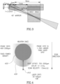
- the separation between the points of impact of the ablative and the feedback beams is further determined by the distance between the center of the catheter, from which the laser radiation is transmitted, and the target area in the duodenal wall, which again is dependent on the diameter/radius of the expandable member (e.g. 16-23 mm), as illustratively depicted in FIG. 3 .
- the magnitude of the delay between the ablative beam and the feedback beam, at a specific point on the duodenal wall may be determined by the degree of beam separation as well as the rotational speed.
- the feedback beam may have a larger spot diameter than that of the ablative beam, as illustrated in FIG. 4 , which schematically illustrates a difference in spot diameter, here a feedback (probe) spot diameter 420 of 400-2000 microns and an ablation spot diameter 410 of 50-200 microns.
- the difference in spot diameter may be achieved, for example, by using an optical fiber having a larger core diameter for the feedback beam, as compared to the ablative beam.
- the ablative beam may be transmitted through the core of the double cladded fiber, whereas the feedback beam may be transmitted (and collected) through the clad.
- both laser beams are transmitted through the core fiber, and clad is used to collect scattering light from the ablation spot.
- a delay of x 0.1-0.5 s obtained for example by a spot separation of 700-3000 microns and a scan velocity of 1.5 mm/s, sufficient time passes for photo thermal and/or photo chemistry processes to take place, prior to the feedback beam reaching the region of impact.
- due to larger spot diameter of the feedback beam almost an entire region of impact may be evaluated, such as region of impact 430 caused by a previous impingement of the laser beam.
- FIG. 5A and FIG. 5B which illustratively depicts a setup 500a suitable when using two separate optical fibers for delivering the ablative and the feedback beams and a setup 500b suitable when using a combiner (e.g. a double cladded optical fiber), respectively.
- a significant difference in spot diameter between the ablative beam and the feed beam is more easily achieved using separate optical fibers, as depicted in setup 500a as compared to setup 500b.
- balloon 600 may include longitudinal marks 610.
- Longitudinal marks 610 may be configured to enable determining the rotational speed of the first and/or second laser beam and/or the diameter of the balloon.
- the angular velocity of the ablative beam may be determined by measuring the modulation frequency of the feedback obtained from lines 610 upon rotation.
- longitudinal lines 610 may be positioned at an external or internal surface of the balloon.
- the longitudinal lines may be made of metal, dyes, thermal based marks or other material that does not expand, in order to ensure that the longitudinal lines maintain a constant width required to enable determination of balloon diameter.
- balloon 600 may further include circumferential lines (width bands) 620 configured to determine that linear velocity of the catheter and/or of the laser transmitting element.
- balloon 610 may be coated with parylene to increase thermal resistance, to deal with heating effects on the tissue exposed to the ablating laser beam and/or to direct the laser beam.
- balloon segments 710 may be interconnected by connection points 720 allowing bending (e.g. 120 degrees bending) there between, so as to enable expansion of the duodenum lumen, while maintaining its 3D shape in both its folded and its inflated configuration, as shown in FIG. 8A and FIG 8B , respectively.
- balloon segments 710 may have an essentially same length and/or diameter, as here illustrated, and/or be of different length and/or diameters to comply with anatomy, option not shown.
- balloon segments 710 may be inflated simultaneously or sequentially.
- a distal of balloon segments 710 may be configured to be first inflated so as to enable the application of push forces and extension of the catheter at the end of the catheter closest to the ablation target (e.g. the beginning of the duodenum after the pylorus junction).
- each balloon segment, or some balloon segments (e.g. the distal most balloon segment) may include longitudinal and/or circumferential marks, as described in FIG. 6 .
- balloon segments 710 may be coated with parylene to increase thermal resistance, to deal with eating effects on the tissue exposed to the ablating laser beam and/or to direct the laser beam.
- FIG. 9 schematically illustrates an expandable member, here a balloon 900, configured to stretch and/or widen the duodenum to a predetermined diameter or range of diameters, according to some embodiments.
- Balloon 900 includes a support member 910 configured to stabilize the laser transmitting element within balloon 900.
- the support member may be made from a shape memory material, such as, but not limited to, nitinol.
- Example 1 Correlation between ablation power and detected feedback signal power.
- FIG. 10 shows an essentially linear correlation between ablation power and the intensity of the signal detected by the feedback sensor, using the setup depicted in FIG. 5A . This clearly indicates that the ablation/feedback system disclosed herein can be utilized to evaluate the extent of impact of an ablative beam on duodenal tissue.
- a standard catheter was used to collect the back scattered/back reflected beam during in-vivo tissue ablation of a pig duodenum using a 1550 nm, 10 W laser. Concurrently with ablation (at a predetermined delay), the ablative impact on the duodenal tissue was evaluated using a second laser, having a wavelength of 980 nm, as essentially described in in FIG. 5A , with lateral separation of the beams.
- evaluation of the power intensity of the feedback beam clearly showed an overall homogenous ablation of the duodenal tissue. Furthermore, at one point, during which the ablative laser beam was directed to a same target area for a prolonged period of time, an ablation crossing an upper ablation threshold level (indicated by horizontal line T2), was readily identified.
- This result clearly demonstrates that the system and method for ablative feedback evaluation, disclosed herein, enables immediate identification of excessive ablation events, thus enabling halting and/or terminating the ablation procedure prior to damage (such as, but not limited to, perforation) being caused to the tissue.
Landscapes
- Health & Medical Sciences (AREA)
- Life Sciences & Earth Sciences (AREA)
- Surgery (AREA)
- Physics & Mathematics (AREA)
- Engineering & Computer Science (AREA)
- Medical Informatics (AREA)
- Animal Behavior & Ethology (AREA)
- Veterinary Medicine (AREA)
- Biomedical Technology (AREA)
- Heart & Thoracic Surgery (AREA)
- Public Health (AREA)
- Molecular Biology (AREA)
- General Health & Medical Sciences (AREA)
- Biophysics (AREA)
- Pathology (AREA)
- Nuclear Medicine, Radiotherapy & Molecular Imaging (AREA)
- Otolaryngology (AREA)
- Optics & Photonics (AREA)
- Electromagnetism (AREA)
- Gastroenterology & Hepatology (AREA)
- Physiology (AREA)
- Endocrinology (AREA)
- Plasma & Fusion (AREA)
- High Energy & Nuclear Physics (AREA)
- Radiology & Medical Imaging (AREA)
- Laser Surgery Devices (AREA)
Applications Claiming Priority (3)
| Application Number | Priority Date | Filing Date | Title |
|---|---|---|---|
| US201662374842P | 2016-08-14 | 2016-08-14 | |
| EP17841209.4A EP3496800B1 (en) | 2016-08-14 | 2017-08-14 | Apparatus for nerve ablation in the wall of the gastointestinal tract |
| PCT/IL2017/050898 WO2018033910A1 (en) | 2016-08-14 | 2017-08-14 | Apparatus and method for nerve ablation in the wall of the gastointestinal tract |
Related Parent Applications (1)
| Application Number | Title | Priority Date | Filing Date |
|---|---|---|---|
| EP17841209.4A Division EP3496800B1 (en) | 2016-08-14 | 2017-08-14 | Apparatus for nerve ablation in the wall of the gastointestinal tract |
Publications (3)
| Publication Number | Publication Date |
|---|---|
| EP3811999A1 EP3811999A1 (en) | 2021-04-28 |
| EP3811999B1 true EP3811999B1 (en) | 2023-10-04 |
| EP3811999C0 EP3811999C0 (en) | 2023-10-04 |
Family
ID=61196487
Family Applications (2)
| Application Number | Title | Priority Date | Filing Date |
|---|---|---|---|
| EP20200072.5A Active EP3811999B1 (en) | 2016-08-14 | 2017-08-14 | Apparatus for nerve ablation in the wall of the gastointestinal tract |
| EP17841209.4A Active EP3496800B1 (en) | 2016-08-14 | 2017-08-14 | Apparatus for nerve ablation in the wall of the gastointestinal tract |
Family Applications After (1)
| Application Number | Title | Priority Date | Filing Date |
|---|---|---|---|
| EP17841209.4A Active EP3496800B1 (en) | 2016-08-14 | 2017-08-14 | Apparatus for nerve ablation in the wall of the gastointestinal tract |
Country Status (5)
| Country | Link |
|---|---|
| US (3) | US11109913B2 (enExample) |
| EP (2) | EP3811999B1 (enExample) |
| JP (3) | JP7048606B2 (enExample) |
| CN (2) | CN110139688B (enExample) |
| WO (1) | WO2018033910A1 (enExample) |
Families Citing this family (25)
| Publication number | Priority date | Publication date | Assignee | Title |
|---|---|---|---|---|
| EP2950878B1 (en) * | 2013-01-31 | 2021-10-20 | Digma Medical Ltd. | Endoluminal duodenal catheter for reducing neural activity |
| US10537387B2 (en) | 2014-04-17 | 2020-01-21 | Digma Medical Ltd. | Methods and systems for blocking neural activity in an organ of a subject, preferably in the small intestine or the duodenum |
| CN110139688B (zh) | 2016-08-14 | 2022-03-18 | 迪格玛医疗有限公司 | 用于胃肠道壁中的神经消融的装置和方法 |
| US10575904B1 (en) * | 2016-08-14 | 2020-03-03 | Digma Medical Ltd. | Apparatus and method for selective submucosal ablation |
| US20190380589A1 (en) * | 2018-06-18 | 2019-12-19 | Medlumics S.L. | Catheter with merged optical tissue evaluation and laser ablation |
| US12402946B2 (en) | 2019-06-19 | 2025-09-02 | Boston Scientific Scimed, Inc. | Breakdown of laser pulse energy for breakup of vascular calcium |
| US11911574B2 (en) | 2019-06-26 | 2024-02-27 | Boston Scientific Scimed, Inc. | Fortified balloon inflation fluid for plasma system to disrupt vascular lesions |
| US12274497B2 (en) | 2019-12-18 | 2025-04-15 | Bolt Medical, Inc. | Multiplexer for laser-driven intravascular lithotripsy device |
| US12446961B2 (en) | 2020-02-10 | 2025-10-21 | Bolt Medical, Inc. | System and method for pressure monitoring within a catheter system |
| US20230071306A1 (en) * | 2020-02-21 | 2023-03-09 | Intuitive Surgical Operations, Inc. | Systems and methods for delivering targeted therapy |
| US12702479B2 (en) | 2020-03-09 | 2026-08-11 | Boston Scientific Scimed, Inc. | Laser pulse shaping to enhance conversion efficiency and protect fiber optic delivery system for disruption of vascular calcium |
| US12611253B2 (en) * | 2020-03-18 | 2026-04-28 | Boston Scientific Scimed, Inc. | Optical analyzer assembly and method for intravascular lithotripsy device |
| US20210353359A1 (en) | 2020-05-12 | 2021-11-18 | Bolt Medical, Inc. | Active alignment system and method for optimizing optical coupling of multiplexer for laser-driven intravascular lithotripsy device |
| US12295654B2 (en) | 2020-06-03 | 2025-05-13 | Boston Scientific Scimed, Inc. | System and method for maintaining balloon integrity within intravascular lithotripsy device with plasma generator |
| CN114681053B (zh) * | 2020-12-31 | 2023-07-04 | 华科精准(北京)医疗科技有限公司 | 磁共振引导激光消融治疗系统 |
| EP4277548B1 (en) | 2021-01-12 | 2025-06-04 | Bolt Medical, Inc. | Balloon assembly for valvuloplasty catheter system |
| US12672915B2 (en) | 2021-08-24 | 2026-07-07 | Boston Scientific Scimed, Inc. | Connector for multiplexer optical coupling |
| EP4440462B1 (en) | 2021-12-01 | 2026-04-29 | Alleima Karlsruhe GmbH | Ablating apparatus |
| US11839391B2 (en) | 2021-12-14 | 2023-12-12 | Bolt Medical, Inc. | Optical emitter housing assembly for intravascular lithotripsy device |
| CN114271936B (zh) * | 2021-12-29 | 2024-03-08 | 烟台龙驰光电技术有限公司 | 一种自主调控温度的激光消融针 |
| CN118785863A (zh) * | 2021-12-30 | 2024-10-15 | 奥普思瑞斯股份有限公司 | 一次性光纤设备 |
| US12533184B2 (en) | 2022-04-02 | 2026-01-27 | Boston Scientific Scimed, Inc. | Optical connector assembly for intravascular lithotripsy device |
| US12653608B2 (en) | 2022-08-07 | 2026-06-16 | Boston Scientific Scimed, Inc. | Optoelectrical connector for intravascular lithotripsy device |
| CN115887878B (zh) * | 2023-01-06 | 2026-04-21 | 上海佳沐垚医疗科技有限公司 | 球囊导管装置 |
| CN116780325B (zh) * | 2023-08-18 | 2023-11-03 | 深圳市中科融光医疗科技有限公司 | 一种激光高效耦合的光路装置及工作方法 |
Family Cites Families (85)
| Publication number | Priority date | Publication date | Assignee | Title |
|---|---|---|---|---|
| US3858577A (en) | 1974-04-05 | 1975-01-07 | Univ Southern California | Fiber optic laser light delivery system |
| US5693043A (en) | 1985-03-22 | 1997-12-02 | Massachusetts Institute Of Technology | Catheter for laser angiosurgery |
| GB2205502B (en) | 1986-10-29 | 1991-04-17 | Okamoto Ind Inc | Balloon endoscopy |
| US5029574A (en) | 1988-04-14 | 1991-07-09 | Okamoto Industries, Inc. | Endoscopic balloon with a protective film thereon |
| US5194005A (en) * | 1988-12-21 | 1993-03-16 | Laser Medical Technology, Inc. | Surgical and dental procedures using laser radiation |
| US6134003A (en) | 1991-04-29 | 2000-10-17 | Massachusetts Institute Of Technology | Method and apparatus for performing optical measurements using a fiber optic imaging guidewire, catheter or endoscope |
| US6485413B1 (en) | 1991-04-29 | 2002-11-26 | The General Hospital Corporation | Methods and apparatus for forward-directed optical scanning instruments |
| US6319247B1 (en) | 1993-05-07 | 2001-11-20 | Visx, Incorporated | Systems and methods for corneal surface ablation to correct hyperopia |
| FR2723305B1 (fr) | 1994-08-04 | 1996-11-22 | Kamami Yves Victor | Piece a main pour dispositif de chirurgie du nez par laser |
| US7468060B2 (en) | 1998-02-19 | 2008-12-23 | Respiratory Diagnostic, Inc. | Systems and methods for treating obesity and other gastrointestinal conditions |
| WO2004112883A2 (en) | 2003-06-20 | 2004-12-29 | Metacure N.V. | Hepatic device for treatment or glucose detection |
| AU5275600A (en) | 1999-05-18 | 2000-12-05 | Silhouette Medical Inc. | Surgical weight control device |
| US9033961B2 (en) | 1999-07-14 | 2015-05-19 | Cardiofocus, Inc. | Cardiac ablation catheters for forming overlapping lesions |
| US7096070B1 (en) | 2000-02-09 | 2006-08-22 | Transneuronix, Inc. | Medical implant device for electrostimulation using discrete micro-electrodes |
| MXPA03000014A (es) | 2000-06-28 | 2004-09-13 | Ira Sanders | Metodos para utilizar con fines beneficiosos toxina tetanica en animales. |
| US6832114B1 (en) | 2000-11-21 | 2004-12-14 | Advanced Bionics Corporation | Systems and methods for modulation of pancreatic endocrine secretion and treatment of diabetes |
| US6654630B2 (en) | 2001-05-31 | 2003-11-25 | Infraredx, Inc. | Apparatus and method for the optical imaging of tissue samples |
| US20030144708A1 (en) | 2002-01-29 | 2003-07-31 | Starkebaum Warren L. | Methods and apparatus for retarding stomach emptying for treatment of eating disorders |
| US7239912B2 (en) | 2002-03-22 | 2007-07-03 | Leptos Biomedical, Inc. | Electric modulation of sympathetic nervous system |
| US7162303B2 (en) | 2002-04-08 | 2007-01-09 | Ardian, Inc. | Renal nerve stimulation method and apparatus for treatment of patients |
| US20040082859A1 (en) | 2002-07-01 | 2004-04-29 | Alan Schaer | Method and apparatus employing ultrasound energy to treat body sphincters |
| US20130197555A1 (en) | 2002-07-01 | 2013-08-01 | Recor Medical, Inc. | Intraluminal devices and methods for denervation |
| US7444183B2 (en) | 2003-02-03 | 2008-10-28 | Enteromedics, Inc. | Intraluminal electrode apparatus and method |
| US7112195B2 (en) | 2003-04-21 | 2006-09-26 | Cynosure, Inc. | Esophageal lesion treatment method |
| DE20306411U1 (de) | 2003-04-24 | 2003-07-03 | Trumpf Laser Marking Systems AG, Grüsch | Anordnung eines optischen Elements im Strahlengang eines Laserstrahls |
| US20040215180A1 (en) | 2003-04-25 | 2004-10-28 | Medtronic, Inc. | Ablation of stomach lining to treat obesity |
| US7149574B2 (en) | 2003-06-09 | 2006-12-12 | Palo Alto Investors | Treatment of conditions through electrical modulation of the autonomic nervous system |
| US20070060906A1 (en) | 2003-08-18 | 2007-03-15 | Wei Wu | Method, reagent, and device for embolizing blood vessels in tumors with ultrasonic radiation micro-bubble reagent |
| US7054690B2 (en) | 2003-10-22 | 2006-05-30 | Intrapace, Inc. | Gastrointestinal stimulation device |
| US20050251116A1 (en) * | 2004-05-05 | 2005-11-10 | Minnow Medical, Llc | Imaging and eccentric atherosclerotic material laser remodeling and/or ablation catheter |
| US20060122584A1 (en) | 2004-10-27 | 2006-06-08 | Bommannan D B | Apparatus and method to treat heart disease using lasers to form microchannels |
| EP1814630A4 (en) | 2004-11-15 | 2008-05-07 | Christopher Decharms | APPLICATIONS FOR NERVE BEND STIMULATION BY LIGHT |
| US20070016262A1 (en) | 2005-07-13 | 2007-01-18 | Betastim, Ltd. | Gi and pancreatic device for treating obesity and diabetes |
| US20070121196A1 (en) | 2005-09-29 | 2007-05-31 | The General Hospital Corporation | Method and apparatus for method for viewing and analyzing of one or more biological samples with progressively increasing resolutions |
| US7620455B2 (en) | 2005-10-25 | 2009-11-17 | Cyberonics, Inc. | Cranial nerve stimulation to treat eating disorders |
| US20090234417A1 (en) | 2005-11-10 | 2009-09-17 | Electrocore, Inc. | Methods And Apparatus For The Treatment Of Metabolic Disorders |
| EP1986545A2 (en) | 2006-02-01 | 2008-11-05 | The General Hospital Corporation | Apparatus for applying a plurality of electro-magnetic radiations to a sample |
| CN101404950B (zh) | 2006-02-01 | 2015-08-19 | 通用医疗公司 | 用于利用保形激光治疗过程来监视和获得样本的至少一个部分的信息并且向样本的至少一个部分提供电磁辐射的方法和系统 |
| WO2007149602A2 (en) | 2006-02-01 | 2007-12-27 | The General Hospital Corporation | Methods and systems for providing electromagnetic radiation to at least one portion of a sample using conformal laser therapy procedures |
| WO2007139920A2 (en) | 2006-05-26 | 2007-12-06 | Endosphere, Inc. | Improvements in methods and devices to curb appetite and/or reduce food intake |
| US20080086180A1 (en) | 2006-10-05 | 2008-04-10 | Omry Ben-Ezra | Techniques for gall bladder stimulation |
| AU2008212104A1 (en) | 2007-02-07 | 2008-08-14 | Duocure, Inc. | Duodenal stimulation devices and methods for the treatment of conditions relating to eating disorders |
| US8641711B2 (en) | 2007-05-04 | 2014-02-04 | Covidien Lp | Method and apparatus for gastrointestinal tract ablation for treatment of obesity |
| US7835074B2 (en) | 2007-06-05 | 2010-11-16 | Sterling Lc | Mini-scope for multi-directional imaging |
| US7925351B2 (en) | 2007-06-13 | 2011-04-12 | Betastim, Ltd. | Gastrointestinal device for treating obesity and diabetes |
| US8160678B2 (en) | 2007-06-18 | 2012-04-17 | Ethicon Endo-Surgery, Inc. | Methods and devices for repairing damaged or diseased tissue using a scanning beam assembly |
| JP5052279B2 (ja) | 2007-09-28 | 2012-10-17 | 富士フイルム株式会社 | 光断層画像化装置 |
| US20090253990A1 (en) | 2007-12-06 | 2009-10-08 | Children's Hospital Of Orange County | Optical diagnosis of hemophilic joint effusion |
| RU2494697C2 (ru) * | 2007-12-28 | 2013-10-10 | Конинклейке Филипс Электроникс, Н.В. | Устройство для абляции ткани с механизмом обратной связи образования фотоакустического участка поражения |
| AU2009231849A1 (en) | 2008-03-31 | 2009-10-08 | Lenticular Research Group, Llc | Processes and apparatus for preventing, delaying or ameliorating one or more symptoms of presbyopia |
| US10368838B2 (en) | 2008-03-31 | 2019-08-06 | Intuitive Surgical Operations, Inc. | Surgical tools for laser marking and laser cutting |
| US10736689B2 (en) | 2008-08-20 | 2020-08-11 | Prostacare Pty Ltd | Low-corrosion electrode for treating tissue |
| US20100268297A1 (en) | 2009-02-24 | 2010-10-21 | Hans Neisz | Duodenal Stimulation To Induce Satiety |
| JP5743380B2 (ja) | 2009-03-06 | 2015-07-01 | キヤノン株式会社 | 光断層撮像装置および光断層撮像方法 |
| US8551096B2 (en) | 2009-05-13 | 2013-10-08 | Boston Scientific Scimed, Inc. | Directional delivery of energy and bioactives |
| US20110208175A1 (en) | 2010-02-24 | 2011-08-25 | Medtronic Vascular, Inc. | Methods for Treating Sleep Apnea Via Renal Denervation |
| US20110257641A1 (en) | 2010-04-14 | 2011-10-20 | Roger Hastings | Phototherapy for renal denervation |
| WO2011156736A2 (en) | 2010-06-11 | 2011-12-15 | Kuhn Joseph A | Targeted mucosal treatment of obesity and diabetes |
| US9060755B2 (en) | 2010-10-26 | 2015-06-23 | Medtronic Ardian Luxembourg S.A.R.L. | Neuromodulation cryotherapeutic devices and associated systems and methods |
| JP6046631B2 (ja) * | 2010-11-19 | 2016-12-21 | ボストン サイエンティフィック サイムド,インコーポレイテッドBoston Scientific Scimed,Inc. | 腎神経の検出切除装置 |
| KR102584819B1 (ko) | 2011-01-19 | 2023-10-05 | 프랙틸 헬쓰, 인코포레이티드 | 조직의 치료를 위한 장치 및 방법 |
| CA2866825A1 (en) | 2011-03-09 | 2012-09-13 | Gastro-Shape Technologies, Inc. | Methods for reducing the absorption of nutrients through the gastrointestinal tract |
| WO2013012892A2 (en) | 2011-07-19 | 2013-01-24 | The Board Of Trustees Of The Leland Stanford Junior University | Treatments for diabetes mellitus and obesity |
| EP2548606A1 (en) | 2011-07-20 | 2013-01-23 | Florian Netzer | Catheter for creating a spatially separated vessel section |
| JP5926806B2 (ja) * | 2011-09-22 | 2016-05-25 | ザ・ジョージ・ワシントン・ユニバーシティThe George Washingtonuniversity | アブレーションされた組織を視覚化するシステムと方法 |
| WO2013082587A1 (en) | 2011-12-02 | 2013-06-06 | Enterx, Inc. | Method for modulating the enteric nervous system to treat a disorder |
| EP2788078B1 (en) | 2011-12-09 | 2020-09-02 | Metavention, Inc. | Therapeutic neuromodulation of the hepatic system |
| EP4066764A1 (en) | 2012-02-27 | 2022-10-05 | Fractyl Health, Inc. | Heat ablation systems and devices for the treatment of tissue |
| CA2869904C (en) | 2012-04-19 | 2020-04-21 | Fractyl Laboratories, Inc. | Systems for expanding tissue prior to energy ablation |
| US9883906B2 (en) | 2012-04-22 | 2018-02-06 | Newuro, B.V. | Bladder tissue modification for overactive bladder disorders |
| US20140017635A1 (en) | 2012-07-13 | 2014-01-16 | GME German Medical Engineering GmbH | Medical treatment apparatus with laser pulses in the femtosecond range |
| US20140025069A1 (en) | 2012-07-17 | 2014-01-23 | Boston Scientific Scimed, Inc. | Renal nerve modulation catheter design |
| WO2014022436A1 (en) | 2012-07-30 | 2014-02-06 | Fractyl Laboratories Inc. | Electrical energy ablation systems, devices and methods for the treatment of tissue |
| EP2882362B1 (en) | 2012-08-09 | 2024-01-03 | Fractyl Health, Inc. | Ablation systems, devices and methods for the treatment of tissue |
| US20140088575A1 (en) | 2012-09-27 | 2014-03-27 | Trimedyne, Inc. | Devices for effective and uniform denervation of nerves and unique methods of use thereof |
| WO2014055997A1 (en) | 2012-10-05 | 2014-04-10 | Fractyl Laboratories Inc. | Methods, systems and devices for performing multiple treatments on a patient |
| EP2950878B1 (en) | 2013-01-31 | 2021-10-20 | Digma Medical Ltd. | Endoluminal duodenal catheter for reducing neural activity |
| EP2950731A4 (en) * | 2013-01-31 | 2017-01-04 | Eximo Medical Ltd. | Hybrid catheter apparatus and methods |
| CN203524766U (zh) * | 2013-02-07 | 2014-04-09 | 上海魅丽纬叶医疗科技有限公司 | 经腔穿壁神经消融导管及其设备 |
| EP3003461B1 (en) | 2013-06-04 | 2019-05-01 | Fractyl Laboratories, Inc. | Systems and devices for reducing the luminal surface area of the gastrointestinal tract |
| JP2016534787A (ja) * | 2013-10-25 | 2016-11-10 | マーケイター メドシステムズ, インコーポレイテッド | 細胞毒性、細胞増殖抑制、または抗新生物剤の局所送達による気管支開存度の維持 |
| US10537387B2 (en) * | 2014-04-17 | 2020-01-21 | Digma Medical Ltd. | Methods and systems for blocking neural activity in an organ of a subject, preferably in the small intestine or the duodenum |
| EP3220994B1 (en) | 2014-11-17 | 2021-01-06 | TriReme Medical, LLC | Balloon catheter system |
| US10575904B1 (en) | 2016-08-14 | 2020-03-03 | Digma Medical Ltd. | Apparatus and method for selective submucosal ablation |
| CN110139688B (zh) | 2016-08-14 | 2022-03-18 | 迪格玛医疗有限公司 | 用于胃肠道壁中的神经消融的装置和方法 |
-
2017
- 2017-08-14 CN CN201780062892.XA patent/CN110139688B/zh active Active
- 2017-08-14 JP JP2019529322A patent/JP7048606B2/ja active Active
- 2017-08-14 CN CN202210208484.3A patent/CN114569245B/zh active Active
- 2017-08-14 EP EP20200072.5A patent/EP3811999B1/en active Active
- 2017-08-14 EP EP17841209.4A patent/EP3496800B1/en active Active
- 2017-08-14 US US16/323,741 patent/US11109913B2/en active Active
- 2017-08-14 WO PCT/IL2017/050898 patent/WO2018033910A1/en not_active Ceased
-
2021
- 2021-08-04 US US17/393,989 patent/US20210361354A1/en not_active Abandoned
-
2022
- 2022-03-23 JP JP2022047377A patent/JP2022095708A/ja active Pending
-
2024
- 2024-03-04 US US18/595,037 patent/US12446960B2/en active Active
- 2024-03-19 JP JP2024043461A patent/JP7660733B2/ja active Active
Also Published As
| Publication number | Publication date |
|---|---|
| EP3811999A1 (en) | 2021-04-28 |
| JP2022095708A (ja) | 2022-06-28 |
| CN114569245A (zh) | 2022-06-03 |
| CN110139688A (zh) | 2019-08-16 |
| EP3496800A4 (en) | 2019-08-14 |
| US20210361354A1 (en) | 2021-11-25 |
| CN110139688B (zh) | 2022-03-18 |
| JP7660733B2 (ja) | 2025-04-11 |
| US20190167349A1 (en) | 2019-06-06 |
| CN114569245B (zh) | 2024-09-17 |
| JP7048606B2 (ja) | 2022-04-05 |
| WO2018033910A1 (en) | 2018-02-22 |
| JP2024069592A (ja) | 2024-05-21 |
| EP3496800A1 (en) | 2019-06-19 |
| US11109913B2 (en) | 2021-09-07 |
| US20240197399A1 (en) | 2024-06-20 |
| JP2019527610A (ja) | 2019-10-03 |
| US12446960B2 (en) | 2025-10-21 |
| EP3496800B1 (en) | 2020-11-04 |
| EP3811999C0 (en) | 2023-10-04 |
Similar Documents
| Publication | Publication Date | Title |
|---|---|---|
| US12446960B2 (en) | Apparatus and method for nerve ablation in the wall of the gastrointestinal tract | |
| US11564743B1 (en) | Apparatus and method for selective submucosal ablation | |
| US20220211437A1 (en) | Methods and systems for reducing neural activity in an organ of a subject | |
| AU2007319871B2 (en) | System and method for determining dosimetry in ophthalmic photomedicine | |
| US20200107881A1 (en) | Methods and systems for blocking neural activity in an organ of a subject, preferably in the small intestine or the duodenum | |
| US20150359595A1 (en) | Hybrid catheter apparatus and methods | |
| EP3476350B1 (en) | Combined laser beam splitter retrieval device | |
| AU2011203543B2 (en) | System and method for determining dosimetry in ophthalmic photomedicine |
Legal Events
| Date | Code | Title | Description |
|---|---|---|---|
| PUAI | Public reference made under article 153(3) epc to a published international application that has entered the european phase |
Free format text: ORIGINAL CODE: 0009012 |
|
| STAA | Information on the status of an ep patent application or granted ep patent |
Free format text: STATUS: THE APPLICATION HAS BEEN PUBLISHED |
|
| AC | Divisional application: reference to earlier application |
Ref document number: 3496800 Country of ref document: EP Kind code of ref document: P |
|
| AK | Designated contracting states |
Kind code of ref document: A1 Designated state(s): AL AT BE BG CH CY CZ DE DK EE ES FI FR GB GR HR HU IE IS IT LI LT LU LV MC MK MT NL NO PL PT RO RS SE SI SK SM TR |
|
| STAA | Information on the status of an ep patent application or granted ep patent |
Free format text: STATUS: REQUEST FOR EXAMINATION WAS MADE |
|
| 17P | Request for examination filed |
Effective date: 20211027 |
|
| RBV | Designated contracting states (corrected) |
Designated state(s): AL AT BE BG CH CY CZ DE DK EE ES FI FR GB GR HR HU IE IS IT LI LT LU LV MC MK MT NL NO PL PT RO RS SE SI SK SM TR |
|
| GRAP | Despatch of communication of intention to grant a patent |
Free format text: ORIGINAL CODE: EPIDOSNIGR1 |
|
| STAA | Information on the status of an ep patent application or granted ep patent |
Free format text: STATUS: GRANT OF PATENT IS INTENDED |
|
| RIC1 | Information provided on ipc code assigned before grant |
Ipc: A61B 18/14 20060101ALN20230330BHEP Ipc: A61B 17/00 20060101ALN20230330BHEP Ipc: A61B 18/00 20060101ALN20230330BHEP Ipc: A61B 5/00 20060101ALI20230330BHEP Ipc: A61B 18/20 20060101ALI20230330BHEP Ipc: A61B 6/00 20060101ALI20230330BHEP Ipc: A61B 18/24 20060101ALI20230330BHEP Ipc: A61B 18/18 20060101ALI20230330BHEP Ipc: A61B 18/22 20060101ALI20230330BHEP Ipc: A61B 18/28 20060101ALI20230330BHEP Ipc: A61M 25/10 20130101AFI20230330BHEP |
|
| RIC1 | Information provided on ipc code assigned before grant |
Ipc: A61B 18/14 20060101ALN20230403BHEP Ipc: A61B 17/00 20060101ALN20230403BHEP Ipc: A61B 18/00 20060101ALN20230403BHEP Ipc: A61B 5/00 20060101ALI20230403BHEP Ipc: A61B 18/20 20060101ALI20230403BHEP Ipc: A61B 6/00 20060101ALI20230403BHEP Ipc: A61B 18/24 20060101ALI20230403BHEP Ipc: A61B 18/18 20060101ALI20230403BHEP Ipc: A61B 18/22 20060101ALI20230403BHEP Ipc: A61B 18/28 20060101ALI20230403BHEP Ipc: A61M 25/10 20130101AFI20230403BHEP |
|
| INTG | Intention to grant announced |
Effective date: 20230502 |
|
| RIC1 | Information provided on ipc code assigned before grant |
Ipc: A61B 18/14 20060101ALN20230414BHEP Ipc: A61B 17/00 20060101ALN20230414BHEP Ipc: A61B 18/00 20060101ALN20230414BHEP Ipc: A61B 5/00 20060101ALI20230414BHEP Ipc: A61B 18/20 20060101ALI20230414BHEP Ipc: A61B 6/00 20060101ALI20230414BHEP Ipc: A61B 18/24 20060101ALI20230414BHEP Ipc: A61B 18/18 20060101ALI20230414BHEP Ipc: A61B 18/22 20060101ALI20230414BHEP Ipc: A61B 18/28 20060101ALI20230414BHEP Ipc: A61M 25/10 20130101AFI20230414BHEP |
|
| GRAS | Grant fee paid |
Free format text: ORIGINAL CODE: EPIDOSNIGR3 |
|
| GRAA | (expected) grant |
Free format text: ORIGINAL CODE: 0009210 |
|
| STAA | Information on the status of an ep patent application or granted ep patent |
Free format text: STATUS: THE PATENT HAS BEEN GRANTED |
|
| AC | Divisional application: reference to earlier application |
Ref document number: 3496800 Country of ref document: EP Kind code of ref document: P |
|
| AK | Designated contracting states |
Kind code of ref document: B1 Designated state(s): AL AT BE BG CH CY CZ DE DK EE ES FI FR GB GR HR HU IE IS IT LI LT LU LV MC MK MT NL NO PL PT RO RS SE SI SK SM TR |
|
| REG | Reference to a national code |
Ref country code: GB Ref legal event code: FG4D |
|
| REG | Reference to a national code |
Ref country code: CH Ref legal event code: EP |
|
| REG | Reference to a national code |
Ref country code: IE Ref legal event code: FG4D |
|
| REG | Reference to a national code |
Ref country code: DE Ref legal event code: R096 Ref document number: 602017075099 Country of ref document: DE |
|
| U01 | Request for unitary effect filed |
Effective date: 20231027 |
|
| U07 | Unitary effect registered |
Designated state(s): AT BE BG DE DK EE FI FR IT LT LU LV MT NL PT SE SI Effective date: 20231102 |
|
| PG25 | Lapsed in a contracting state [announced via postgrant information from national office to epo] |
Ref country code: GR Free format text: LAPSE BECAUSE OF FAILURE TO SUBMIT A TRANSLATION OF THE DESCRIPTION OR TO PAY THE FEE WITHIN THE PRESCRIBED TIME-LIMIT Effective date: 20240105 |
|
| PG25 | Lapsed in a contracting state [announced via postgrant information from national office to epo] |
Ref country code: IS Free format text: LAPSE BECAUSE OF FAILURE TO SUBMIT A TRANSLATION OF THE DESCRIPTION OR TO PAY THE FEE WITHIN THE PRESCRIBED TIME-LIMIT Effective date: 20240204 |
|
| PG25 | Lapsed in a contracting state [announced via postgrant information from national office to epo] |
Ref country code: ES Free format text: LAPSE BECAUSE OF FAILURE TO SUBMIT A TRANSLATION OF THE DESCRIPTION OR TO PAY THE FEE WITHIN THE PRESCRIBED TIME-LIMIT Effective date: 20231004 |
|
| PG25 | Lapsed in a contracting state [announced via postgrant information from national office to epo] |
Ref country code: IS Free format text: LAPSE BECAUSE OF FAILURE TO SUBMIT A TRANSLATION OF THE DESCRIPTION OR TO PAY THE FEE WITHIN THE PRESCRIBED TIME-LIMIT Effective date: 20240204 Ref country code: GR Free format text: LAPSE BECAUSE OF FAILURE TO SUBMIT A TRANSLATION OF THE DESCRIPTION OR TO PAY THE FEE WITHIN THE PRESCRIBED TIME-LIMIT Effective date: 20240105 Ref country code: ES Free format text: LAPSE BECAUSE OF FAILURE TO SUBMIT A TRANSLATION OF THE DESCRIPTION OR TO PAY THE FEE WITHIN THE PRESCRIBED TIME-LIMIT Effective date: 20231004 |
|
| PG25 | Lapsed in a contracting state [announced via postgrant information from national office to epo] |
Ref country code: RS Free format text: LAPSE BECAUSE OF FAILURE TO SUBMIT A TRANSLATION OF THE DESCRIPTION OR TO PAY THE FEE WITHIN THE PRESCRIBED TIME-LIMIT Effective date: 20231004 Ref country code: PL Free format text: LAPSE BECAUSE OF FAILURE TO SUBMIT A TRANSLATION OF THE DESCRIPTION OR TO PAY THE FEE WITHIN THE PRESCRIBED TIME-LIMIT Effective date: 20231004 Ref country code: NO Free format text: LAPSE BECAUSE OF FAILURE TO SUBMIT A TRANSLATION OF THE DESCRIPTION OR TO PAY THE FEE WITHIN THE PRESCRIBED TIME-LIMIT Effective date: 20240104 Ref country code: HR Free format text: LAPSE BECAUSE OF FAILURE TO SUBMIT A TRANSLATION OF THE DESCRIPTION OR TO PAY THE FEE WITHIN THE PRESCRIBED TIME-LIMIT Effective date: 20231004 |
|
| REG | Reference to a national code |
Ref country code: DE Ref legal event code: R097 Ref document number: 602017075099 Country of ref document: DE |
|
| PG25 | Lapsed in a contracting state [announced via postgrant information from national office to epo] |
Ref country code: CZ Free format text: LAPSE BECAUSE OF FAILURE TO SUBMIT A TRANSLATION OF THE DESCRIPTION OR TO PAY THE FEE WITHIN THE PRESCRIBED TIME-LIMIT Effective date: 20231004 |
|
| PG25 | Lapsed in a contracting state [announced via postgrant information from national office to epo] |
Ref country code: SK Free format text: LAPSE BECAUSE OF FAILURE TO SUBMIT A TRANSLATION OF THE DESCRIPTION OR TO PAY THE FEE WITHIN THE PRESCRIBED TIME-LIMIT Effective date: 20231004 |
|
| PG25 | Lapsed in a contracting state [announced via postgrant information from national office to epo] |
Ref country code: SM Free format text: LAPSE BECAUSE OF FAILURE TO SUBMIT A TRANSLATION OF THE DESCRIPTION OR TO PAY THE FEE WITHIN THE PRESCRIBED TIME-LIMIT Effective date: 20231004 Ref country code: SK Free format text: LAPSE BECAUSE OF FAILURE TO SUBMIT A TRANSLATION OF THE DESCRIPTION OR TO PAY THE FEE WITHIN THE PRESCRIBED TIME-LIMIT Effective date: 20231004 Ref country code: RO Free format text: LAPSE BECAUSE OF FAILURE TO SUBMIT A TRANSLATION OF THE DESCRIPTION OR TO PAY THE FEE WITHIN THE PRESCRIBED TIME-LIMIT Effective date: 20231004 Ref country code: CZ Free format text: LAPSE BECAUSE OF FAILURE TO SUBMIT A TRANSLATION OF THE DESCRIPTION OR TO PAY THE FEE WITHIN THE PRESCRIBED TIME-LIMIT Effective date: 20231004 |
|
| PLBE | No opposition filed within time limit |
Free format text: ORIGINAL CODE: 0009261 |
|
| STAA | Information on the status of an ep patent application or granted ep patent |
Free format text: STATUS: NO OPPOSITION FILED WITHIN TIME LIMIT |
|
| 26N | No opposition filed |
Effective date: 20240705 |
|
| U20 | Renewal fee for the european patent with unitary effect paid |
Year of fee payment: 8 Effective date: 20240814 |
|
| REG | Reference to a national code |
Ref country code: CH Ref legal event code: PL |
|
| GBPC | Gb: european patent ceased through non-payment of renewal fee |
Effective date: 20240814 |
|
| PG25 | Lapsed in a contracting state [announced via postgrant information from national office to epo] |
Ref country code: CH Free format text: LAPSE BECAUSE OF NON-PAYMENT OF DUE FEES Effective date: 20240831 Ref country code: MC Free format text: LAPSE BECAUSE OF FAILURE TO SUBMIT A TRANSLATION OF THE DESCRIPTION OR TO PAY THE FEE WITHIN THE PRESCRIBED TIME-LIMIT Effective date: 20231004 |
|
| PG25 | Lapsed in a contracting state [announced via postgrant information from national office to epo] |
Ref country code: GB Free format text: LAPSE BECAUSE OF NON-PAYMENT OF DUE FEES Effective date: 20240814 |
|
| PG25 | Lapsed in a contracting state [announced via postgrant information from national office to epo] |
Ref country code: IE Free format text: LAPSE BECAUSE OF NON-PAYMENT OF DUE FEES Effective date: 20240814 |
|
| U20 | Renewal fee for the european patent with unitary effect paid |
Year of fee payment: 9 Effective date: 20250821 |
|
| PG25 | Lapsed in a contracting state [announced via postgrant information from national office to epo] |
Ref country code: CY Free format text: LAPSE BECAUSE OF FAILURE TO SUBMIT A TRANSLATION OF THE DESCRIPTION OR TO PAY THE FEE WITHIN THE PRESCRIBED TIME-LIMIT; INVALID AB INITIO Effective date: 20170814 |
|
| PG25 | Lapsed in a contracting state [announced via postgrant information from national office to epo] |
Ref country code: HU Free format text: LAPSE BECAUSE OF FAILURE TO SUBMIT A TRANSLATION OF THE DESCRIPTION OR TO PAY THE FEE WITHIN THE PRESCRIBED TIME-LIMIT; INVALID AB INITIO Effective date: 20170814 |
|
| PG25 | Lapsed in a contracting state [announced via postgrant information from national office to epo] |
Ref country code: TR Free format text: LAPSE BECAUSE OF FAILURE TO SUBMIT A TRANSLATION OF THE DESCRIPTION OR TO PAY THE FEE WITHIN THE PRESCRIBED TIME-LIMIT Effective date: 20231004 |