EP3809012B1 - Vordergabelpositionsabhängige dämpfung für fahrräder und motorräder - Google Patents
Vordergabelpositionsabhängige dämpfung für fahrräder und motorräder Download PDFInfo
- Publication number
- EP3809012B1 EP3809012B1 EP19204131.7A EP19204131A EP3809012B1 EP 3809012 B1 EP3809012 B1 EP 3809012B1 EP 19204131 A EP19204131 A EP 19204131A EP 3809012 B1 EP3809012 B1 EP 3809012B1
- Authority
- EP
- European Patent Office
- Prior art keywords
- piston
- valve body
- damper
- piston rod
- inner tube
- Prior art date
- Legal status (The legal status is an assumption and is not a legal conclusion. Google has not performed a legal analysis and makes no representation as to the accuracy of the status listed.)
- Active
Links
Images
Classifications
-
- B—PERFORMING OPERATIONS; TRANSPORTING
- B62—LAND VEHICLES FOR TRAVELLING OTHERWISE THAN ON RAILS
- B62K—CYCLES; CYCLE FRAMES; CYCLE STEERING DEVICES; RIDER-OPERATED TERMINAL CONTROLS SPECIALLY ADAPTED FOR CYCLES; CYCLE AXLE SUSPENSIONS; CYCLE SIDE-CARS, FORECARS, OR THE LIKE
- B62K25/00—Axle suspensions
- B62K25/04—Axle suspensions for mounting axles resiliently on cycle frame or fork
- B62K25/06—Axle suspensions for mounting axles resiliently on cycle frame or fork with telescopic fork, e.g. including auxiliary rocking arms
- B62K25/08—Axle suspensions for mounting axles resiliently on cycle frame or fork with telescopic fork, e.g. including auxiliary rocking arms for front wheel
-
- F—MECHANICAL ENGINEERING; LIGHTING; HEATING; WEAPONS; BLASTING
- F16—ENGINEERING ELEMENTS AND UNITS; GENERAL MEASURES FOR PRODUCING AND MAINTAINING EFFECTIVE FUNCTIONING OF MACHINES OR INSTALLATIONS; THERMAL INSULATION IN GENERAL
- F16F—SPRINGS; SHOCK-ABSORBERS; MEANS FOR DAMPING VIBRATION
- F16F9/00—Springs, vibration-dampers, shock-absorbers, or similarly-constructed movement-dampers using a fluid or the equivalent as damping medium
- F16F9/10—Springs, vibration-dampers, shock-absorbers, or similarly-constructed movement-dampers using a fluid or the equivalent as damping medium using liquid only; using a fluid of which the nature is immaterial
- F16F9/14—Devices with one or more members, e.g. pistons, vanes, moving to and fro in chambers and using throttling effect
- F16F9/16—Devices with one or more members, e.g. pistons, vanes, moving to and fro in chambers and using throttling effect involving only straight-line movement of the effective parts
- F16F9/18—Devices with one or more members, e.g. pistons, vanes, moving to and fro in chambers and using throttling effect involving only straight-line movement of the effective parts with a closed cylinder and a piston separating two or more working spaces therein
- F16F9/185—Bitubular units
-
- F—MECHANICAL ENGINEERING; LIGHTING; HEATING; WEAPONS; BLASTING
- F16—ENGINEERING ELEMENTS AND UNITS; GENERAL MEASURES FOR PRODUCING AND MAINTAINING EFFECTIVE FUNCTIONING OF MACHINES OR INSTALLATIONS; THERMAL INSULATION IN GENERAL
- F16F—SPRINGS; SHOCK-ABSORBERS; MEANS FOR DAMPING VIBRATION
- F16F9/00—Springs, vibration-dampers, shock-absorbers, or similarly-constructed movement-dampers using a fluid or the equivalent as damping medium
- F16F9/32—Details
- F16F9/3207—Constructional features
- F16F9/3214—Constructional features of pistons
-
- F—MECHANICAL ENGINEERING; LIGHTING; HEATING; WEAPONS; BLASTING
- F16—ENGINEERING ELEMENTS AND UNITS; GENERAL MEASURES FOR PRODUCING AND MAINTAINING EFFECTIVE FUNCTIONING OF MACHINES OR INSTALLATIONS; THERMAL INSULATION IN GENERAL
- F16F—SPRINGS; SHOCK-ABSORBERS; MEANS FOR DAMPING VIBRATION
- F16F9/00—Springs, vibration-dampers, shock-absorbers, or similarly-constructed movement-dampers using a fluid or the equivalent as damping medium
- F16F9/32—Details
- F16F9/3207—Constructional features
- F16F9/3235—Constructional features of cylinders
- F16F9/3257—Constructional features of cylinders in twin-tube type devices
-
- F—MECHANICAL ENGINEERING; LIGHTING; HEATING; WEAPONS; BLASTING
- F16—ENGINEERING ELEMENTS AND UNITS; GENERAL MEASURES FOR PRODUCING AND MAINTAINING EFFECTIVE FUNCTIONING OF MACHINES OR INSTALLATIONS; THERMAL INSULATION IN GENERAL
- F16F—SPRINGS; SHOCK-ABSORBERS; MEANS FOR DAMPING VIBRATION
- F16F9/00—Springs, vibration-dampers, shock-absorbers, or similarly-constructed movement-dampers using a fluid or the equivalent as damping medium
- F16F9/32—Details
- F16F9/34—Special valve constructions; Shape or construction of throttling passages
- F16F9/3405—Throttling passages in or on piston body, e.g. slots
-
- F—MECHANICAL ENGINEERING; LIGHTING; HEATING; WEAPONS; BLASTING
- F16—ENGINEERING ELEMENTS AND UNITS; GENERAL MEASURES FOR PRODUCING AND MAINTAINING EFFECTIVE FUNCTIONING OF MACHINES OR INSTALLATIONS; THERMAL INSULATION IN GENERAL
- F16F—SPRINGS; SHOCK-ABSORBERS; MEANS FOR DAMPING VIBRATION
- F16F9/00—Springs, vibration-dampers, shock-absorbers, or similarly-constructed movement-dampers using a fluid or the equivalent as damping medium
- F16F9/32—Details
- F16F9/36—Special sealings, including sealings or guides for piston-rods
- F16F9/368—Sealings in pistons
-
- F—MECHANICAL ENGINEERING; LIGHTING; HEATING; WEAPONS; BLASTING
- F16—ENGINEERING ELEMENTS AND UNITS; GENERAL MEASURES FOR PRODUCING AND MAINTAINING EFFECTIVE FUNCTIONING OF MACHINES OR INSTALLATIONS; THERMAL INSULATION IN GENERAL
- F16F—SPRINGS; SHOCK-ABSORBERS; MEANS FOR DAMPING VIBRATION
- F16F9/00—Springs, vibration-dampers, shock-absorbers, or similarly-constructed movement-dampers using a fluid or the equivalent as damping medium
- F16F9/32—Details
- F16F9/48—Arrangements for providing different damping effects at different parts of the stroke
-
- F—MECHANICAL ENGINEERING; LIGHTING; HEATING; WEAPONS; BLASTING
- F16—ENGINEERING ELEMENTS AND UNITS; GENERAL MEASURES FOR PRODUCING AND MAINTAINING EFFECTIVE FUNCTIONING OF MACHINES OR INSTALLATIONS; THERMAL INSULATION IN GENERAL
- F16F—SPRINGS; SHOCK-ABSORBERS; MEANS FOR DAMPING VIBRATION
- F16F9/00—Springs, vibration-dampers, shock-absorbers, or similarly-constructed movement-dampers using a fluid or the equivalent as damping medium
- F16F9/32—Details
- F16F9/50—Special means providing automatic damping adjustment, i.e. self-adjustment of damping by particular sliding movements of a valve element, other than flexions or displacement of valve discs; Special means providing self-adjustment of spring characteristics
- F16F9/512—Means responsive to load action, i.e. static load on the damper or dynamic fluid pressure changes in the damper, e.g. due to changes in velocity
- F16F9/5126—Piston, or piston-like valve elements
-
- F—MECHANICAL ENGINEERING; LIGHTING; HEATING; WEAPONS; BLASTING
- F16—ENGINEERING ELEMENTS AND UNITS; GENERAL MEASURES FOR PRODUCING AND MAINTAINING EFFECTIVE FUNCTIONING OF MACHINES OR INSTALLATIONS; THERMAL INSULATION IN GENERAL
- F16F—SPRINGS; SHOCK-ABSORBERS; MEANS FOR DAMPING VIBRATION
- F16F13/00—Units comprising springs of the non-fluid type as well as vibration-dampers, shock-absorbers, or fluid springs
- F16F13/005—Units comprising springs of the non-fluid type as well as vibration-dampers, shock-absorbers, or fluid springs comprising both a wound spring and a damper, e.g. a friction damper
- F16F13/007—Units comprising springs of the non-fluid type as well as vibration-dampers, shock-absorbers, or fluid springs comprising both a wound spring and a damper, e.g. a friction damper the damper being a fluid damper
-
- F—MECHANICAL ENGINEERING; LIGHTING; HEATING; WEAPONS; BLASTING
- F16—ENGINEERING ELEMENTS AND UNITS; GENERAL MEASURES FOR PRODUCING AND MAINTAINING EFFECTIVE FUNCTIONING OF MACHINES OR INSTALLATIONS; THERMAL INSULATION IN GENERAL
- F16F—SPRINGS; SHOCK-ABSORBERS; MEANS FOR DAMPING VIBRATION
- F16F2222/00—Special physical effects, e.g. nature of damping effects
- F16F2222/12—Fluid damping
-
- F—MECHANICAL ENGINEERING; LIGHTING; HEATING; WEAPONS; BLASTING
- F16—ENGINEERING ELEMENTS AND UNITS; GENERAL MEASURES FOR PRODUCING AND MAINTAINING EFFECTIVE FUNCTIONING OF MACHINES OR INSTALLATIONS; THERMAL INSULATION IN GENERAL
- F16F—SPRINGS; SHOCK-ABSORBERS; MEANS FOR DAMPING VIBRATION
- F16F2228/00—Functional characteristics, e.g. variability, frequency-dependence
- F16F2228/06—Stiffness
- F16F2228/066—Variable stiffness
-
- F—MECHANICAL ENGINEERING; LIGHTING; HEATING; WEAPONS; BLASTING
- F16—ENGINEERING ELEMENTS AND UNITS; GENERAL MEASURES FOR PRODUCING AND MAINTAINING EFFECTIVE FUNCTIONING OF MACHINES OR INSTALLATIONS; THERMAL INSULATION IN GENERAL
- F16F—SPRINGS; SHOCK-ABSORBERS; MEANS FOR DAMPING VIBRATION
- F16F2230/00—Purpose; Design features
- F16F2230/30—Sealing arrangements
-
- F—MECHANICAL ENGINEERING; LIGHTING; HEATING; WEAPONS; BLASTING
- F16—ENGINEERING ELEMENTS AND UNITS; GENERAL MEASURES FOR PRODUCING AND MAINTAINING EFFECTIVE FUNCTIONING OF MACHINES OR INSTALLATIONS; THERMAL INSULATION IN GENERAL
- F16F—SPRINGS; SHOCK-ABSORBERS; MEANS FOR DAMPING VIBRATION
- F16F2230/00—Purpose; Design features
- F16F2230/36—Holes, slots or the like
-
- F—MECHANICAL ENGINEERING; LIGHTING; HEATING; WEAPONS; BLASTING
- F16—ENGINEERING ELEMENTS AND UNITS; GENERAL MEASURES FOR PRODUCING AND MAINTAINING EFFECTIVE FUNCTIONING OF MACHINES OR INSTALLATIONS; THERMAL INSULATION IN GENERAL
- F16F—SPRINGS; SHOCK-ABSORBERS; MEANS FOR DAMPING VIBRATION
- F16F2230/00—Purpose; Design features
- F16F2230/42—Multiple pistons
-
- F—MECHANICAL ENGINEERING; LIGHTING; HEATING; WEAPONS; BLASTING
- F16—ENGINEERING ELEMENTS AND UNITS; GENERAL MEASURES FOR PRODUCING AND MAINTAINING EFFECTIVE FUNCTIONING OF MACHINES OR INSTALLATIONS; THERMAL INSULATION IN GENERAL
- F16F—SPRINGS; SHOCK-ABSORBERS; MEANS FOR DAMPING VIBRATION
- F16F2232/00—Nature of movement
- F16F2232/08—Linear
-
- F—MECHANICAL ENGINEERING; LIGHTING; HEATING; WEAPONS; BLASTING
- F16—ENGINEERING ELEMENTS AND UNITS; GENERAL MEASURES FOR PRODUCING AND MAINTAINING EFFECTIVE FUNCTIONING OF MACHINES OR INSTALLATIONS; THERMAL INSULATION IN GENERAL
- F16F—SPRINGS; SHOCK-ABSORBERS; MEANS FOR DAMPING VIBRATION
- F16F2234/00—Shape
- F16F2234/02—Shape cylindrical
-
- F—MECHANICAL ENGINEERING; LIGHTING; HEATING; WEAPONS; BLASTING
- F16—ENGINEERING ELEMENTS AND UNITS; GENERAL MEASURES FOR PRODUCING AND MAINTAINING EFFECTIVE FUNCTIONING OF MACHINES OR INSTALLATIONS; THERMAL INSULATION IN GENERAL
- F16F—SPRINGS; SHOCK-ABSORBERS; MEANS FOR DAMPING VIBRATION
- F16F2234/00—Shape
- F16F2234/04—Shape conical
Definitions
- the present disclosure relates to shock absorbers for vehicle suspensions and more specifically to a damper for a telescopic fork leg for a front fork of a vehicle such as a motorcycle.
- the shock absorber comprises a cylinder and a piston rod assembly comprising a piston, said cylinder and piston being attached to different parts of the vehicle such that the piston moves within the cylinder at compression and extension of the shock absorber.
- the shock absorber also comprises spring means configured to bias the shock absorber towards its extended position.
- the spring means is typically a coil spring or air spring.
- a working medium is provided within the shock absorber and pumped though the shock absorber by the piston at compression and/or extension of the shock absorber, wherein the working medium is guided through one or more flow paths controlling the flow rate, to thereby provide damping of movement of the shock absorber.
- the flow paths commonly comprise shim stacks and other types of flow resistance regulating mechanisms, such as non-return valves, affecting the damping provided by the shock absorber.
- shock absorber such that its damping is position-dependent, for example offering more damping at the end of a compression stroke than in the beginning of the compression stroke. Also, it is often desirable to configure a shock absorber such that it offers different damping at different compression rates of the shock absorber.
- the front suspension and the rear suspension have different designs.
- a modern motorcycle rear suspension often has a swing arm acting on a telescoping shock absorber.
- the compression of the shock absorber is thus not linear to the rotation of the swing arm carrying the rear wheel, which in turn makes the damping position-dependent.
- a damper for a telescopic fork leg with a position dependent damping characteristic is known from US3024874 .
- An object of the invention is thus to provide an improved damper for a telescopic fork leg for a front fork of a vehicle exhibiting a position-dependent damping characteristic offering higher damping further into a compression stroke than in the beginning of a compression stroke of the damper.
- the damper as defined in claim 1, with specific embodiments defined by the dependent claims.
- the damper comprises a twin-tube cylinder comprising an inner tube and an outer tube defining a chamber between the inner tube and the outer tube.
- the second piston separates the intermediate volume from an outer volume inside the inner tube.
- the inner tube is provided with at least one outlet hole through the wall of the inner tube, said outlet hole being positioned such that a sealing portion of the second piston is movable past the at least one outlet hole (19) at compression of the damper.
- the inner tube is provided with at least one return hole through the wall of the inner tube, said at least one return hole being positioned such that it connects the chamber of the twin-tube cylinder to the outer volume.
- the bypass passage allows fluid to leave the intermediate volume as fluid enters the intermediate volume from the inner volume.
- the valve assembly of the first piston provides a first damping characteristic independently of the position of the piston rod in the cylinder.
- the bypass passage is restricted since the available area for fluid to leave the intermediate volume through is restricted or blocked.
- the damper may comprise a plurality of said outlet holes, wherein the outlet holes are distributed along the length of the inner tube.
- the size of the outlet holes may decrease along the length of the damper with larger holes further out and smaller holes further in.
- the decreasing size of the holes enable a high degree of variation of the area of the outlet holes in response to movement of the sealing portion at compression of the damper.
- the frustoconical second piston thus opens outwards, i.e. towards the outlet end of the twin tube cylinder through which outlet end the piston rod is outwardly moved at extension of the damper. Accordingly, the inner end is the opposite end of the twin tube cylinder.
- the valve body is movable into the inner space of the second piston to restrict fluid flow through the second piston.
- it is thus not decisive to the throttling function of the valve body if it is the vale body or the second piston that moves, since it is merely their relative position that determines the throttling of fluid flow through the second piston.
- fluid pressure is used to move the second piston and/or the valve body at compression and extension of the damper their design and movements must be adapted accordingly such that they open and close when intended.
- the fluid pressure in the damper is able to force the second piston outwards, towards the valve body, upon compression of the damper. If the valve body is also movable back and forth along the piston rod, the valve body and the second piston may move together for some distance. At extension of the damper the second piston is movable far enough inwards in the damper to bring the valve body out of its restricting position and into its open position. This enables a lower flow resistance through the second piston at extension of the damper than at compression of the damper.
- the valve body may in its restricting position together with the second piston define a first fluid chamber delimited by a first pressure surface of the valve body, wherein the first pressure surface is configured to provide a first area for fluid pressure to act on for forcing the valve body outwards against the force of the biasing means.
- the fluid chamber is always open for some pressure to be transmitted from the intermediate volume and can thus enable a spread of fluid pressure over the first area to thereby force the valve body outwards
- the valve body is provided with a second pressure surface radially outside of the first pressure surface, wherein the valve body and the second piston are configured such that when the valve body is in the restricting position, the valve body seals to the second piston to prevent fluid pressure in the first fluid chamber from reaching the second pressure surface, and wherein the valve body and the second piston are configured such that the sealing engagement that separates the first pressure surface from the second pressure surface is interrupted once the valve body is moved a predetermined distance away from the second piston against the force of the biasing means.
- the second fluid channel of the second piston may comprise one or more first radial fluid passages through the second piston, wherein the valve body is frustoconical and comprises one or more second radial fluid passages configured such that the first and second radial fluid passages align when the valve body is at the outer end of the second operational range and the second piston is at the outer end of the first operational range.
- a second aspect of the disclosure relates to a telescopic fork leg for a front fork of a vehicle, said telescopic fork leg comprising a damper as described above.
- Non-linear damping is commonly only found in rear bicycle suspensions comprising a swing arm connected to a linear damper through a mechanism enabling linear movement of the suspended wheel to be translated into a non-linear compression movement of the damper, thereby achieving non-linear damping despite the use of a linear damper.
- a third aspect of the disclosure relates to a front fork for a vehicle, said front fork comprising a telescopic fork leg as described above.
- a fourth aspect of the disclosure relates to a vehicle comprising a front fork as described above.
- the vehicle may be a bicycle, such as a mountain bike or a motocross bike.
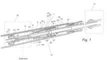
- a damper 1 according to a first embodiment will hereinafter be described with reference to the appended drawings.
- the damper 1 is typically used in a front fork of a vehicle such as a mountain bike.
- the damper 1 comprises a twin-tube cylinder 5 comprising an inner tube 6 and an outer tube 7 defining a chamber 8 between the inner tube 6 and the outer tube 7.
- the tubes 6, 7 are made of aluminum but could in other embodiments be made of any other suitable metal or other suitable material.
- the damper 1 comprises a piston rod assembly comprising a piston rod 9 having an inner end portion 10 inside the cylinder 5 and an outer end portion 11 outside the cylinder 5.
- the piston rod assembly is movable within the cylinder 5 back and forth between a compressed position and an extended position.
- a first piston 12 is attached to the inner end portion 10 of the piston rod.
- the first piston 12 is provided with at least one first fluid channel 13 through the first piston 12 and a valve assembly 14 configured to control flow resistance through the first fluid channel 13 at compression and/or extension of the damper 1.
- the damper 1 also comprises a second piston 15 attached to the piston rod 9 between the first piston 12 and the outer end portion 11 of the piston rod 9 such that the first piston 12 and the second piston 15 are spaced apart together defining an intermediate volume 16 inside the cylinder 5 between the first piston 12 and the second piston 15.
- the first piston 12 separates the intermediate volume 16 from an inner volume 17 inside the inner tube 6.
- the second piston 15 separates the intermediate volume 16 from an outer volume 18 inside the inner tube 6.
- the inner tube 6 is provided with a plurality of outlet holes 19 through the wall of the inner tube 6. In other embodiments one outlet hole 19 could alternatively be provided but that would provide less control of the damping throughout a compression stroke of the damper as compared to the provision of a higher number of outlet holes 19 distributed along the length of the damper 1.
- the outlet holes 19 are distributed along the length of the inner tube 6 and positioned such that a sealing portion 20 of the second piston 15 is movable past the outlet holes 19.
- the inner tube 6 is provided with one return hole 21 through the wall of the inner tube 6 but could in other embodiments alternatively comprise additional return holes 21.
- the return hole 21 is positioned such that it connects the chamber 8 of the twin-tube cylinder 5 to the outer volume 18. The position of the return hole 21 is thus at the outer end of the inner tube 6 such that the second piston 15 cannot move past the return hole 21 at extension of the damper 1 (under normal use of the damper 1).
- the bypass passage allows fluid to leave the intermediate volume 16 as fluid enters the intermediate volume 16 from the inner volume 17.
- the valve assembly of the first piston 12 provides a first damping characteristic independently of the position of the piston rod in the cylinder.
- the bypass passage is restricted since the available area for fluid to leave the intermediate volume 16 through is further restricted or blocked.
- the size of the outlet holes 19 decreases along the length of the damper 1 with larger holes 19 further out and with smaller holes 19 further in along the cylinder 5.
- the size of the outlet holes 19 may alternatively be constant for all outlet holes 19, or have some other distribution. The provision of decreasing size of the outlet holes 19 along the length of the cylinder 5 enable a high degree of variation of the area of the outlet holes in response to movement of the sealing portion at compression of the damper 1.
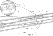
- the second piston 15 is frustoconical with an inner narrower portion sealingly engaging the piston rod 9 and the outer wider sealing portion 20 sealingly engaging the inner tube 6. As shown in the figures, the shape is generally frustoconical its cross-sectional shape widening along the length of the valve body and thus frustoconical should be interpreted accordingly.
- the second piston 15 comprises a second fluid channel 22 connecting the intermediate volume 16 and the outer volume 18.
- the piston rod assembly comprises a valve body 23 attached to the piston rod 9 on the outer volume-side of the second piston 15.
- the valve body 23 and the second piston 15 are movable relative to each other along the piston rod 9 such that the valve body 23 is positionable in, i.e. movable to, a restricting position RP relative to the second piston 15.
- valve body 23 In the restricting position RP, the valve body 23 is seated on an inner circumferential portion 24 of the second piston 15 for mitigating fluid flow through the second fluid channel 22 although any suitable sealing relationship would alternatively work.
- the valve body 23 is positionable in, i.e. movable to, an open position OP relative to the second piston 15 in which open position OP the valve body 23 does not mitigate fluid flow through the second fluid channel 22.
- the frustoconical second piston 15 thus opens outwards, i.e. is widening towards the outer end of the twin tube cylinder 5.
- the outer end of the cylinder 5 is the end through which the piston rod is outwardly moved at extension of the damper 1. Accordingly, the inner end of the cylinder 5 is the opposite end of the twin tube cylinder 5 relative to the outer end.
- the valve body 23 is movable into the inner space of the second piston 15 to restrict fluid flow through the second piston 15.
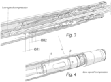
- the second piston 15 is movably attached to the piston rod 9 for movement back and forth along the piston rod 9 through a first operational range OR1 relative to the piston rod 9.
- the first operational range OR1 is configured such that at compression of the damper 1 the second piston 15 is movable towards and/or together/against the valve body for bringing the valve body into the restricting position RP. Also, the first operational range OR1 is such that at extension of the damper 1 the second piston 15 is moveable away from the valve body 21 for bringing the valve body 21 to the open position.
- the valve body 21 is movably attached to the piston rod 9 for movement back and forth along the piston rod 9 through a second operational range OR2 relative to the piston rod 9.
- the piston rod assembly comprises a biasing means 4 configured to bias the valve body towards the restricting position.
- the biasing means is a coil spring, but could alternatively be any other suitable biasing means such as a piece of resilient material for example a suitable elastomer.
- the second operational range OR2 is configured such that when the second piston 15 at compression of the damper 1 is at an outer end portion of the first operational range OR1, the valve body is movable away from the second piston against the biasing force of the spring 4 thereby bringing the valve body 21 towards the open position OP.
- the valve body 21 in its restricting position RP together with the second piston 15 define a first fluid chamber 25 delimited by a first pressure surface 26 of the valve body 21.
- the first pressure surface 26 is configured to provide a first area for fluid pressure to act on for forcing the valve body 21 outwards against the force of the spring 4.
- the valve body 21 is provided with a second pressure surface 27 radially outside of the first pressure surface 26.
- the second pressure surface here has the shape of a radial step in the circumference of the valve body 21 but could in other embodiments have some other shape such as a continuous smooth contour extending radially outwards without any step.
- valve body 21 and the second piston 15 are configured such that when the valve body 21 is in the restricting position RP, the valve body 21 seals to the second piston 15 to prevent fluid pressure in the first fluid chamber from reaching the second pressure surface 27.
- the valve body 21 and the second piston 15 are further configured such that the sealing engagement that separates the first pressure surface 26 from the second pressure surface 27 is interrupted once the valve body is moved a predetermined distance away from the second piston 15 against the force of the spring 4.
- the second pressure surface may alternatively be omitted, although the damper then loses some of the distinctness of the opening characteristics of the flow through the second piston 15 at high speed compression of the damper 1.
- the step in the present embodiment provides the dual function of providing a sealing engagement and an axial stop for the spring to force the valve body against.
- the sealing engagement between the first pressure surface and the second pressure surface could alternatively be corresponding cylindrical portions of the second piston 15 and the valve body 21, wherein said cylindrical portions extend parallel to the piston rod 9.
- the second fluid channel 22 of the second piston 15 comprises a plurality of first radial fluid passages 2 through the second piston 15.
- the valve body 21 is also substantially frustoconical but may in other embodiments alternatively have any other suitable shape.
- the valve body 21 comprises one or more second radial fluid passages 2 configured such that the first 2 and second 3 radial fluid passages align when the valve body 21 is at the outer end of the second operational range OR2 and the second piston is at the outer end of the first operational range OR1. This is shown in Fig. 1 .
- the present disclosure also proposes the use of the above disclosed damper in a telescopic fork leg for a front fork of a vehicle such as a moto cross bike or a mountain bike.
- the telescopic fork leg comprises the damper.
- a front fork comprises two such fork legs but may comprise only one such leg.
- Non-linear damping is commonly only found in rear bicycle suspensions comprising a swing arm connected to a linear damper through a mechanism enabling linear movement of the suspended wheel to be translated into a non-linear compression movement of the damper, thereby achieving non-linear damping despite the use of a linear damper.
Landscapes
- Engineering & Computer Science (AREA)
- General Engineering & Computer Science (AREA)
- Mechanical Engineering (AREA)
- Physics & Mathematics (AREA)
- Fluid Mechanics (AREA)
- Fluid-Damping Devices (AREA)
Claims (13)
- Dämpfer (1) für ein teleskopisches Gabelbein für eine vordere Gabel eines Fahrzeugs,wobei der Dämpfer (1) einen Doppelrohrzylinder (5) aufweist, der ein inneres Rohr (6) und ein äußeres Rohr (7) aufweist, die eine Kammer (8) zwischen dem inneren Rohr (6) und dem äußeren Rohr (7) definieren,wobei der Dämpfer (1) eine Kolbenstangenbaugruppe aufweist, die eine Kolbenstange (9) aufweist, die einen inneren Endabschnitt (10) in dem Zylinder (5) und einen äußeren Endabschnitt (11) außerhalb des Zylinders (5) aufweist,wobei die Kolbenstangenbaugruppe in dem Zylinder (5) zwischen einer komprimierten Position und einer ausgefahrenen Position hin- und herbewegt werden kann,wobei ein erster Kolben (12) an dem inneren Endabschnitt (10) der Kolbenstange (9) befestigt ist,wobei der erste Kolben (12) mit mindestens einem ersten Fluidkanal (13) durch den ersten Kolben (12) und einer Ventilbaugruppe (14), die eingerichtet ist, um den Fluidstrom durch den ersten Fluidkanal (13) zu steuern, versehen ist,wobei ein zweiter Kolben (15) an der Kolbenstange (9) zwischen dem ersten Kolben (12) und dem äußeren Endabschnitt (11) der Kolbenstange (9) befestigt ist, sodass der erste Kolben (12) und der zweite Kolben (15) so voneinander beabstandet sind, dass sie zusammen ein Zwischenvolumen (16) in dem Zylinder (5) zwischen dem ersten Kolben (12) und dem zweiten Kolben (15) definieren,wobei der erste Kolben (12) das Zwischenvolumen (16) von einem inneren Volumen (17) in dem inneren Rohr (6) trennt,wobei der zweite Kolben (15) das Zwischenvolumen (16) von einem äußeren Volumen (18) in dem inneren Rohr (6) trennt,wobei das innere Rohr (6) mit mindestens einem Auslassloch (19) durch die Wand des inneren Rohrs (6) versehen ist und wobei das innere Rohr (6) mit mindestens einem Rücklaufloch (21) durch die Wand des inneren Rohrs (6) versehen ist, wobei das mindestens eine Rücklaufloch (21) so platziert ist, dass es die Kammer (8) der beiden Rohrzylinder (5) mit dem äußeren Volumen (18) verbindet, dadurch gekennzeichnet, dass das Auslassloch (19) so positioniert ist, dass ein Dichtabschnitt (20) des zweiten Kolbens (15) an dem mindestens einen Auslassloch (19) vorbei bewegt werden kann, wenn der Dämpfer (1) komprimiert wird.
- Dämpfer (1) nach Anspruch 1, aufweisend mehrere der Auslasslöcher (19), wobei die Auslasslöcher (19) entlang der Länge des inneren Rohrs (6) verteilt sind.
- Dämpfer (1) nach Anspruch 2, wobei die Größe der Auslasslöcher (19) entlang der Länge des Dämpfers (1) abnimmt, wobei größere Löcher weiter in Richtung des äußeren Endes des inneren Rohrs und kleinere Löcher weiter in Richtung des inneren Endes des inneren Rohrs angeordnet sind.
- Dämpfer (1) nach einem der Ansprüche 1 bis 3, wobei der zweite Kolben (15) kegelstumpfförmig ist, mit einem inneren engeren Abschnitt, der dichtend in die Kolbenstange (9) eingreift, und einem äußeren breiteren Dichtabschnitt (20), der dichtend in das innere Rohr (6) eingreift, wobei der zweite Kolben (15) einen zweiten Fluidkanal (22) aufweist, der das Zwischenvolumen (16) und das äußere Volumen (18) verbindet,wobei die Kolbenstangenbaugruppe einen Ventilkörper (23) aufweist, der an der Kolbenstange (9) an der äußeren Volumenseite des zweiten Kolbens (15) befestigt ist, undwobei der Ventilkörper (23) und der zweite Kolben (15) relativ zueinander entlang der Kolbenstange (9) beweglich sind, sodass der Ventilkörper (23) in einer einschränkenden Position (RP) relativ zu dem zweiten Kolben (15) platziert werden kann, wobei der Ventilkörper (23) in der einschränkendem Position (RP) an einem inneren Umfangsabschnitt (24) des zweiten Kolbens (15) platziert ist, um den Fluidstrom durch den zweiten Fluidkanal (22) zu verringern und sodass der Ventilkörper (23) in einer offenen Position (OP) relativ zu dem zweiten Kolben (15) beweglich ist, wobei der Ventilkörper (23) in dieser offenen Position (OP) nicht den Fluidstrom durch den zweiten Fluidkanal (22) verringert.
- Dämpfer (1) nach einem der Ansprüche 1 bis 3, wobei der zweite Kolben (15) beweglich an der Kolbenstange (9) befestigt ist, um sich entlang der Kolbenstange (9) durch einen anderen Betriebsbereich (OR1) relativ zu der Kolbenstange (9) hin- und herzubewegen,wobei der erste Betriebsbereich (OR1) so ist, dass der zweite Kolben (15) bei Kompression des Dämpfers (1) in Richtung des Ventilkörpers (23) und zusammen mit diesem beweglich ist, um den Ventilkörper (23) in die eingeschränkte Position (PR) zu bringen, undwobei der erste Betriebsbereich (OR1) so ist, dass beim Ausfahren des Dämpfers (1) der zweite Kolben (15) von dem Ventilkörper (23) weg bewegt werden kann, um den Ventilkörper (23) in die offene Position (OP) zu bringen.
- Dämpfer (1) nach Anspruch 5, wobei der Ventilkörper (23) beweglich an der Kolbenstange (9) befestigt ist, um sich entlang der Kolbenstange (9) durch einen zweiten Betriebsbereich (OR2) relativ zu der Kolbenstange (9) hin- und her zu bewegen,wobei die Kolbenstangenbaugruppe ein Vorbeaufschlagungsmittel (4) aufweist, das eingerichtet ist, um den Ventilkörper (23) in Richtung der einschränkenden Position vorzubeaufschlagen, undwobei der zweite Betriebsbereich (OR2) so ist, dass, wenn sich der zweite Kolben (15) bei Kompression des Dämpfers in einem äußeren Endabschnitt des ersten Betriebsbereichs (OR1) befindet, der Ventilkörper (23) von dem zweiten Kolben (15) gegen die Vorbeaufschlagungskraft des Vorbeaufschlagungsmittels (4) weg bewegt werden kann, um den Ventilkörper (23) in Richtung der offenen Position zu bringen.
- Dämpfer (1) nach Anspruch 6, wobei der Ventilkörper (23) in seiner einschränkenden Position (RP) zusammen mit dem zweiten Kolben (15) eine erste Fluidkammer (25) definiert, die durch eine erste Druckfläche (26) des Ventilkörpers (23) begrenzt ist, wobei die erste Druckfläche (26) eingerichtet ist, um einen ersten Bereich bereitzustellen, auf den Fluiddruck einwirken kann, um den Ventilkörper gegen die Kraft des Vorbeaufschlagungsmittels (4) nach außen zu zwingen.
- Dämpfer (1) nach Anspruch 7, wobei der Ventilkörper (23) mit einer zweiten Druckfläche (27) versehen ist, die sich radial außerhalb der ersten Druckfläche befindet, wobei der Ventilkörper (23) und der zweite Kolben (15) so eingerichtet sind, dass, wenn sich der Ventilkörper (23) in der eingeschränkten Position (RP) befindet, der Ventilkörper (23) den zweiten Kolben (15) abdichtet, um Fluiddruck in der ersten Fluidkammer (26) daran zu hindern, die zweite Druckfläche (27) zu erreichen, und
wobei der Ventilkörper (23) und der zweite Kolben (15) so eingerichtet sind, dass der Dichteingriff, der die erste Druckfläche (26) von der zweiten Druckfläche (27) trennt, unterbrochen wird, wenn der Ventilkörper um eine vorbestimmte Entfernung gegen die Kraft des Vorbeaufschlagungsmittels (4) von dem zweiten Kolben (15) weg bewegt wird. - Dämpfer (1) nach Anspruch 8, wobei der zweite Fluidkanal (22) des zweiten Kolbens (15) eine oder mehrere radiale Fluiddurchgänge (2) durch den zweiten Kolben (15) aufweist, und wobei der Ventilkörper (23) kegelstumpfförmig ist und eine oder mehrere zweite radiale Fluiddurchgänge (3) aufweist, die so eingerichtet sind, dass sich der erste (2) und der zweite (3) radiale Fluiddurchgang aneinander ausrichten, wenn sich der Ventilkörper (23) an einem äußeren Ende des zweiten Betriebsbereichs (OR2) befindet und sich der zweite Kolben (15) an dem äußeren Ende des ersten Betriebsbereichs (OR1) befindet.
- Teleskopisches Gabelbein für eine vordere Gabel eines Fahrzeugs, wobei das teleskopische Gabelbein einen Dämpfer (1) nach einem der vorhergehenden Ansprüche aufweist.
- Vordere Gabel für ein Fahrzeug, wobei die vordere Gabel ein teleskopisches Gabelbein nach Anspruch 10 aufweist.
- Fahrzeug, aufweisend eine vordere Gabel nach Anspruch 11.
- Fahrzeug nach Anspruch 12, wobei das Fahrzeug ein Fahrrad oder ein Motorrad ist.
Priority Applications (3)
| Application Number | Priority Date | Filing Date | Title |
|---|---|---|---|
| EP19204131.7A EP3809012B1 (de) | 2019-10-18 | 2019-10-18 | Vordergabelpositionsabhängige dämpfung für fahrräder und motorräder |
| US17/069,662 US11473644B2 (en) | 2019-10-18 | 2020-10-13 | Front fork position-dependent damping for bicycles and motorcycles |
| CN202011112457.3A CN112682453B (zh) | 2019-10-18 | 2020-10-16 | 用于自行车和摩托车的与位置相关的前叉阻尼 |
Applications Claiming Priority (1)
| Application Number | Priority Date | Filing Date | Title |
|---|---|---|---|
| EP19204131.7A EP3809012B1 (de) | 2019-10-18 | 2019-10-18 | Vordergabelpositionsabhängige dämpfung für fahrräder und motorräder |
Publications (3)
| Publication Number | Publication Date |
|---|---|
| EP3809012A1 EP3809012A1 (de) | 2021-04-21 |
| EP3809012B1 true EP3809012B1 (de) | 2025-06-11 |
| EP3809012C0 EP3809012C0 (de) | 2025-06-11 |
Family
ID=68296140
Family Applications (1)
| Application Number | Title | Priority Date | Filing Date |
|---|---|---|---|
| EP19204131.7A Active EP3809012B1 (de) | 2019-10-18 | 2019-10-18 | Vordergabelpositionsabhängige dämpfung für fahrräder und motorräder |
Country Status (3)
| Country | Link |
|---|---|
| US (1) | US11473644B2 (de) |
| EP (1) | EP3809012B1 (de) |
| CN (1) | CN112682453B (de) |
Families Citing this family (8)
| Publication number | Priority date | Publication date | Assignee | Title |
|---|---|---|---|---|
| US9452654B2 (en) | 2009-01-07 | 2016-09-27 | Fox Factory, Inc. | Method and apparatus for an adjustable damper |
| US9422018B2 (en) * | 2008-11-25 | 2016-08-23 | Fox Factory, Inc. | Seat post |
| US10036443B2 (en) | 2009-03-19 | 2018-07-31 | Fox Factory, Inc. | Methods and apparatus for suspension adjustment |
| US9140325B2 (en) | 2009-03-19 | 2015-09-22 | Fox Factory, Inc. | Methods and apparatus for selective spring pre-load adjustment |
| US11299233B2 (en) | 2009-01-07 | 2022-04-12 | Fox Factory, Inc. | Method and apparatus for an adjustable damper |
| EP3778358B1 (de) | 2010-07-02 | 2023-04-12 | Fox Factory, Inc. | Einstellbare sattelstütze mit positiver verriegelung |
| US10330171B2 (en) | 2012-05-10 | 2019-06-25 | Fox Factory, Inc. | Method and apparatus for an adjustable damper |
| US10183539B2 (en) * | 2014-09-17 | 2019-01-22 | Fox Factory, Inc. | Shock absorber |
Family Cites Families (58)
| Publication number | Priority date | Publication date | Assignee | Title |
|---|---|---|---|---|
| US1183281A (en) * | 1912-08-08 | 1916-05-16 | Martin Derihon | Shock-absorber for vehicles. |
| US1658962A (en) * | 1924-05-10 | 1928-02-14 | Thomas N Aikens | Hydraulic shock absorber |
| US2173574A (en) * | 1936-05-16 | 1939-09-19 | Binder Richard | Slide-controlled hydraulic shock absorber |
| NL105561C (de) * | 1956-02-24 | |||
| US3556268A (en) * | 1969-01-09 | 1971-01-19 | Moog Industries Inc | Gas controlled orifice in hydraulic shock absorber |
| US3693767A (en) * | 1970-11-05 | 1972-09-26 | Hydraulic Products Corp | Adjustable hydraulic shock absorber |
| GB1351333A (en) * | 1971-07-27 | 1974-04-24 | Ibis Engineers Ltd | Snubbing devices or shock absorbers |
| US3889934A (en) * | 1973-12-19 | 1975-06-17 | Houdaille Industries Inc | Hydraulic buffer |
| US4139182A (en) * | 1975-11-26 | 1979-02-13 | Tokico Ltd. | Spring device |
| US4284177A (en) * | 1979-05-14 | 1981-08-18 | Efdyn Corporation | Self-adjusting shock absorber having staged metering |
| US4337849A (en) * | 1980-07-24 | 1982-07-06 | The United States Of America As Represented By The Secretary Of The Army | Energy management damper |
| DE3131262A1 (de) * | 1981-08-07 | 1983-02-24 | Fichtel & Sachs Ag, 8720 Schweinfurt | Hydropneumatischer zweirohr-schwingungsdaempfer mit temperaturkompensation der daempfkraefte |
| US4482035A (en) * | 1982-09-23 | 1984-11-13 | Robert Heideman | Shock absorber |
| US4702355A (en) * | 1985-06-07 | 1987-10-27 | Enertrols, Inc. | Shock absorber with hole-on-groove configuration and with adjusting device |
| DE3900927A1 (de) * | 1989-01-14 | 1990-07-19 | Stabilus Gmbh | Pneumatisches oder hydropneumatisches verstellelement |
| US5050712A (en) * | 1989-04-25 | 1991-09-24 | Enertrols, Inc. | Shock absorber |
| US5018606A (en) * | 1990-01-10 | 1991-05-28 | Lord Corporation | Electrophoretic fluid damper |
| US6112868A (en) * | 1994-10-31 | 2000-09-05 | Gabriel Ride Control Products, Inc. | Externally adjustable dampening control for a shock absorber |
| DE19618055C1 (de) * | 1996-05-06 | 1998-01-15 | Mannesmann Sachs Ag | Kolben-Zylinderaggregat mit wegabhängigem Dämpfkraftfeld |
| US5988330A (en) * | 1997-07-03 | 1999-11-23 | Morris; Jay | Adjustable shock absorber |
| US6047839A (en) * | 1998-02-03 | 2000-04-11 | Huggins; Russell J. | Rail car buffer |
| US6311962B1 (en) * | 1998-02-03 | 2001-11-06 | Fox Factory, Inc. | Shock absorber with external air cylinder spring |
| US6296092B1 (en) * | 1998-10-28 | 2001-10-02 | Fox Factory, Inc. | Position-sensitive shock absorber |
| US6230858B1 (en) * | 1999-08-31 | 2001-05-15 | Delphi Technologies, Inc. | Internally slotted orifice disc for low speed control in automotive dampers |
| DE19944183A1 (de) * | 1999-09-15 | 2001-03-22 | Bayerische Motoren Werke Ag | Hydraulischer Stossdämpfer für Kraftfahrzeuge |
| US6648109B2 (en) * | 2001-09-13 | 2003-11-18 | Meritor Heavy Vehicle Technology, Llc | Adjustable shock absorber |
| US6776269B1 (en) * | 2003-06-18 | 2004-08-17 | Tenneco Automotive Operating Company, Inc. | Twin piston shock absorber |
| US8820494B2 (en) * | 2003-12-15 | 2014-09-02 | Showa Corporation | Hydraulic shock absorbing apparatus of vehicle |
| JP4753238B2 (ja) * | 2005-09-09 | 2011-08-24 | ヤマハ発動機株式会社 | 油圧緩衝器 |
| DE212006000103U1 (de) * | 2006-07-21 | 2009-03-19 | Specialized Bicycle Components, Inc., Morgan Hill | Dämpfungssystem für eine Fahrradfederung |
| US8123006B1 (en) * | 2007-04-13 | 2012-02-28 | Hayes Bicycle Group, Inc. | Lightweight gas spring design with volume compensator incorporated into a suspension fork for two wheeled vehicles |
| FR2922286B1 (fr) * | 2007-10-11 | 2014-02-21 | Eurocopter France | Amortisseur d'un vehicule |
| SE531694C2 (sv) * | 2007-12-19 | 2009-07-07 | Oehlins Racing Ab | Stötdämpare med dubbelkolv |
| KR101229440B1 (ko) * | 2008-02-29 | 2013-02-05 | 주식회사 만도 | 쇽업소버의 스토퍼 |
| JP5180129B2 (ja) * | 2008-04-17 | 2013-04-10 | カヤバ工業株式会社 | フロントフォーク |
| US8240329B1 (en) * | 2008-11-14 | 2012-08-14 | Robust Systems Solutions, LLC | Fluid control valve |
| US9422018B2 (en) * | 2008-11-25 | 2016-08-23 | Fox Factory, Inc. | Seat post |
| US9038791B2 (en) * | 2009-01-07 | 2015-05-26 | Fox Factory, Inc. | Compression isolator for a suspension damper |
| DK2305531T3 (da) * | 2009-10-01 | 2012-04-16 | Voith Patent Gmbh | Indretning til dæmpning af træk- og trykkræfter |
| CZ2010128A3 (cs) * | 2010-02-18 | 2011-08-31 | Pneumatická pružina | |
| JP2011185369A (ja) * | 2010-03-09 | 2011-09-22 | Honda Motor Co Ltd | 車両の緩衝器 |
| JP5723142B2 (ja) * | 2010-12-02 | 2015-05-27 | カヤバ工業株式会社 | 緩衝器 |
| KR101288612B1 (ko) * | 2011-07-21 | 2013-07-22 | 주식회사 만도 | 쇽업소버의 밸브 구조 |
| JP5827871B2 (ja) * | 2011-10-31 | 2015-12-02 | 株式会社ショーワ | 油圧緩衝器 |
| US9133902B2 (en) * | 2013-01-22 | 2015-09-15 | Kyntec Corporation | Shock absorber with variable damping profile |
| CN203892439U (zh) * | 2014-05-28 | 2014-10-22 | 杜信廷 | 一种减震器 |
| ES2818626T3 (es) * | 2014-10-01 | 2021-04-13 | Beijingwest Ind Co Ltd | Conjunto de amortiguador |
| US20180051766A1 (en) * | 2015-09-30 | 2018-02-22 | Hitachi Automotive Systems, Ltd. | Cylinder device |
| JP6577826B2 (ja) * | 2015-10-26 | 2019-09-18 | 株式会社ショーワ | 緩衝器 |
| CN105736623B (zh) * | 2016-04-26 | 2017-11-24 | 长春孔辉汽车科技股份有限公司 | 一种压控可调阻尼减振器 |
| US10393210B2 (en) * | 2016-11-18 | 2019-08-27 | Beijingwest Industries Co., Ltd. | Dual mode hydraulic damper |
| DE102017110889A1 (de) * | 2017-05-18 | 2018-11-22 | Dt Swiss Ag | Stoßeinrichtung insbesondere für ein Fahrrad |
| EP3409972A1 (de) * | 2017-06-01 | 2018-12-05 | Öhlins Racing AB | Unter druck stehendes, teleskopisches bein einer vordergabel, vordergabel und fahrzeug |
| US10746247B2 (en) * | 2018-03-05 | 2020-08-18 | Beijingwest Industries Co., Ltd. | Dual ride damper assembly |
| US11199237B2 (en) * | 2018-08-08 | 2021-12-14 | Raptor Performance Shocks, LLC | Internal bypass shock absorber |
| US11125298B2 (en) * | 2018-08-31 | 2021-09-21 | Birkgrove Pty Ltd. | Shock absorber |
| DE112019006745T5 (de) * | 2019-04-03 | 2022-01-13 | Hitachi Astemo, Ltd. | Stoßdämpfer |
| EP3736467A1 (de) * | 2019-05-03 | 2020-11-11 | The Dynamic Engineering Solution Pty Ltd | Hydraulischer dämpfer |
-
2019
- 2019-10-18 EP EP19204131.7A patent/EP3809012B1/de active Active
-
2020
- 2020-10-13 US US17/069,662 patent/US11473644B2/en active Active
- 2020-10-16 CN CN202011112457.3A patent/CN112682453B/zh active Active
Also Published As
| Publication number | Publication date |
|---|---|
| US20210115997A1 (en) | 2021-04-22 |
| US11473644B2 (en) | 2022-10-18 |
| EP3809012A1 (de) | 2021-04-21 |
| EP3809012C0 (de) | 2025-06-11 |
| CN112682453B (zh) | 2022-10-25 |
| CN112682453A (zh) | 2021-04-20 |
Similar Documents
| Publication | Publication Date | Title |
|---|---|---|
| EP3809012B1 (de) | Vordergabelpositionsabhängige dämpfung für fahrräder und motorräder | |
| US20240309929A1 (en) | Suspension system | |
| US5975258A (en) | Damping force control type hydraulic shock absorber | |
| EP1685480B1 (de) | Stossdämpfer-baugruppe | |
| US6302248B1 (en) | Damping force control type hydraulic shock absorber | |
| JP6654955B2 (ja) | 緩衝器 | |
| CN107567552B (zh) | 可调节减振器 | |
| US5368141A (en) | Displacement sensitive valve mechanism | |
| WO2016199667A1 (ja) | 緩衝器 | |
| EP3631233A1 (de) | Unter druck stehendes, teleskopisches bein einer vordergabel, vordergabel und fahrzeug | |
| US20210222750A1 (en) | Gas spring with travel control | |
| US20170356518A1 (en) | Spring unit | |
| US20100294606A1 (en) | Hydraulic shock absorbing apparatus of vehicle | |
| US12025205B2 (en) | Hydraulic rebound stop pressure relief system | |
| JP6047035B2 (ja) | 車両用液圧緩衝器 | |
| CN112384716B (zh) | 位置依赖型减震器 | |
| JP2517796Y2 (ja) | 液圧緩衝器 | |
| JP2017187048A (ja) | 緩衝器、及び緩衝器の組み立て方法 | |
| EP3848610A1 (de) | Stossdämpfer mit gasfeder und ohne gas-gas-dichtungen | |
| JPH0722149U (ja) | 油圧緩衝器の圧側減衰力調整装置 | |
| JPH07224879A (ja) | 油圧緩衝器のピストンリング構造 | |
| JP2009275813A (ja) | 油圧緩衝器のピストン構造 |
Legal Events
| Date | Code | Title | Description |
|---|---|---|---|
| PUAI | Public reference made under article 153(3) epc to a published international application that has entered the european phase |
Free format text: ORIGINAL CODE: 0009012 |
|
| STAA | Information on the status of an ep patent application or granted ep patent |
Free format text: STATUS: THE APPLICATION HAS BEEN PUBLISHED |
|
| AK | Designated contracting states |
Kind code of ref document: A1 Designated state(s): AL AT BE BG CH CY CZ DE DK EE ES FI FR GB GR HR HU IE IS IT LI LT LU LV MC MK MT NL NO PL PT RO RS SE SI SK SM TR |
|
| AX | Request for extension of the european patent |
Extension state: BA ME |
|
| STAA | Information on the status of an ep patent application or granted ep patent |
Free format text: STATUS: REQUEST FOR EXAMINATION WAS MADE |
|
| 17P | Request for examination filed |
Effective date: 20211021 |
|
| RBV | Designated contracting states (corrected) |
Designated state(s): AL AT BE BG CH CY CZ DE DK EE ES FI FR GB GR HR HU IE IS IT LI LT LU LV MC MK MT NL NO PL PT RO RS SE SI SK SM TR |
|
| P01 | Opt-out of the competence of the unified patent court (upc) registered |
Effective date: 20230528 |
|
| GRAP | Despatch of communication of intention to grant a patent |
Free format text: ORIGINAL CODE: EPIDOSNIGR1 |
|
| STAA | Information on the status of an ep patent application or granted ep patent |
Free format text: STATUS: GRANT OF PATENT IS INTENDED |
|
| INTG | Intention to grant announced |
Effective date: 20240715 |
|
| GRAJ | Information related to disapproval of communication of intention to grant by the applicant or resumption of examination proceedings by the epo deleted |
Free format text: ORIGINAL CODE: EPIDOSDIGR1 |
|
| STAA | Information on the status of an ep patent application or granted ep patent |
Free format text: STATUS: REQUEST FOR EXAMINATION WAS MADE |
|
| INTC | Intention to grant announced (deleted) | ||
| GRAP | Despatch of communication of intention to grant a patent |
Free format text: ORIGINAL CODE: EPIDOSNIGR1 |
|
| STAA | Information on the status of an ep patent application or granted ep patent |
Free format text: STATUS: GRANT OF PATENT IS INTENDED |
|
| INTG | Intention to grant announced |
Effective date: 20250109 |
|
| GRAS | Grant fee paid |
Free format text: ORIGINAL CODE: EPIDOSNIGR3 |
|
| GRAA | (expected) grant |
Free format text: ORIGINAL CODE: 0009210 |
|
| STAA | Information on the status of an ep patent application or granted ep patent |
Free format text: STATUS: THE PATENT HAS BEEN GRANTED |
|
| AK | Designated contracting states |
Kind code of ref document: B1 Designated state(s): AL AT BE BG CH CY CZ DE DK EE ES FI FR GB GR HR HU IE IS IT LI LT LU LV MC MK MT NL NO PL PT RO RS SE SI SK SM TR |
|
| REG | Reference to a national code |
Ref country code: GB Ref legal event code: FG4D |
|
| REG | Reference to a national code |
Ref country code: CH Ref legal event code: EP |
|
| REG | Reference to a national code |
Ref country code: IE Ref legal event code: FG4D |
|
| REG | Reference to a national code |
Ref country code: DE Ref legal event code: R096 Ref document number: 602019070984 Country of ref document: DE |
|
| U01 | Request for unitary effect filed |
Effective date: 20250619 |
|
| U07 | Unitary effect registered |
Designated state(s): AT BE BG DE DK EE FI FR IT LT LU LV MT NL PT RO SE SI Effective date: 20250630 |
|
| P04 | Withdrawal of opt-out of the competence of the unified patent court (upc) registered |
Free format text: CASE NUMBER: APP_30559/2025 Effective date: 20250625 |
|
| PG25 | Lapsed in a contracting state [announced via postgrant information from national office to epo] |
Ref country code: ES Free format text: LAPSE BECAUSE OF FAILURE TO SUBMIT A TRANSLATION OF THE DESCRIPTION OR TO PAY THE FEE WITHIN THE PRESCRIBED TIME-LIMIT Effective date: 20250611 |
|
| PG25 | Lapsed in a contracting state [announced via postgrant information from national office to epo] |
Ref country code: GR Free format text: LAPSE BECAUSE OF FAILURE TO SUBMIT A TRANSLATION OF THE DESCRIPTION OR TO PAY THE FEE WITHIN THE PRESCRIBED TIME-LIMIT Effective date: 20250912 Ref country code: NO Free format text: LAPSE BECAUSE OF FAILURE TO SUBMIT A TRANSLATION OF THE DESCRIPTION OR TO PAY THE FEE WITHIN THE PRESCRIBED TIME-LIMIT Effective date: 20250911 |
|
| PG25 | Lapsed in a contracting state [announced via postgrant information from national office to epo] |
Ref country code: HR Free format text: LAPSE BECAUSE OF FAILURE TO SUBMIT A TRANSLATION OF THE DESCRIPTION OR TO PAY THE FEE WITHIN THE PRESCRIBED TIME-LIMIT Effective date: 20250611 |
|
| PG25 | Lapsed in a contracting state [announced via postgrant information from national office to epo] |
Ref country code: RS Free format text: LAPSE BECAUSE OF FAILURE TO SUBMIT A TRANSLATION OF THE DESCRIPTION OR TO PAY THE FEE WITHIN THE PRESCRIBED TIME-LIMIT Effective date: 20250911 |
|
| U20 | Renewal fee for the european patent with unitary effect paid |
Year of fee payment: 7 Effective date: 20251030 |