EP3804944A1 - Werkzeughälfte und verfahren zum herstellen eines spritzgussteils mit wenigstens einem buchsenartigen einlegeteil - Google Patents
Werkzeughälfte und verfahren zum herstellen eines spritzgussteils mit wenigstens einem buchsenartigen einlegeteil Download PDFInfo
- Publication number
- EP3804944A1 EP3804944A1 EP20199229.4A EP20199229A EP3804944A1 EP 3804944 A1 EP3804944 A1 EP 3804944A1 EP 20199229 A EP20199229 A EP 20199229A EP 3804944 A1 EP3804944 A1 EP 3804944A1
- Authority
- EP
- European Patent Office
- Prior art keywords
- insert
- tool half
- positioning unit
- injection
- area
- Prior art date
- Legal status (The legal status is an assumption and is not a legal conclusion. Google has not performed a legal analysis and makes no representation as to the accuracy of the status listed.)
- Granted
Links
Images



Classifications
-
- B—PERFORMING OPERATIONS; TRANSPORTING
- B29—WORKING OF PLASTICS; WORKING OF SUBSTANCES IN A PLASTIC STATE IN GENERAL
- B29C—SHAPING OR JOINING OF PLASTICS; SHAPING OF MATERIAL IN A PLASTIC STATE, NOT OTHERWISE PROVIDED FOR; AFTER-TREATMENT OF THE SHAPED PRODUCTS, e.g. REPAIRING
- B29C45/00—Injection moulding, i.e. forcing the required volume of moulding material through a nozzle into a closed mould; Apparatus therefor
- B29C45/14—Injection moulding, i.e. forcing the required volume of moulding material through a nozzle into a closed mould; Apparatus therefor incorporating preformed parts or layers, e.g. injection moulding around inserts or for coating articles
- B29C45/14008—Inserting articles into the mould
- B29C45/14032—Transferring the inserts from a storage space inside the mould to the mould cavity
-
- B—PERFORMING OPERATIONS; TRANSPORTING
- B29—WORKING OF PLASTICS; WORKING OF SUBSTANCES IN A PLASTIC STATE IN GENERAL
- B29C—SHAPING OR JOINING OF PLASTICS; SHAPING OF MATERIAL IN A PLASTIC STATE, NOT OTHERWISE PROVIDED FOR; AFTER-TREATMENT OF THE SHAPED PRODUCTS, e.g. REPAIRING
- B29C45/00—Injection moulding, i.e. forcing the required volume of moulding material through a nozzle into a closed mould; Apparatus therefor
- B29C45/14—Injection moulding, i.e. forcing the required volume of moulding material through a nozzle into a closed mould; Apparatus therefor incorporating preformed parts or layers, e.g. injection moulding around inserts or for coating articles
- B29C45/14065—Positioning or centering articles in the mould
-
- B—PERFORMING OPERATIONS; TRANSPORTING
- B29—WORKING OF PLASTICS; WORKING OF SUBSTANCES IN A PLASTIC STATE IN GENERAL
- B29C—SHAPING OR JOINING OF PLASTICS; SHAPING OF MATERIAL IN A PLASTIC STATE, NOT OTHERWISE PROVIDED FOR; AFTER-TREATMENT OF THE SHAPED PRODUCTS, e.g. REPAIRING
- B29C45/00—Injection moulding, i.e. forcing the required volume of moulding material through a nozzle into a closed mould; Apparatus therefor
- B29C45/14—Injection moulding, i.e. forcing the required volume of moulding material through a nozzle into a closed mould; Apparatus therefor incorporating preformed parts or layers, e.g. injection moulding around inserts or for coating articles
- B29C45/14008—Inserting articles into the mould
-
- B—PERFORMING OPERATIONS; TRANSPORTING
- B29—WORKING OF PLASTICS; WORKING OF SUBSTANCES IN A PLASTIC STATE IN GENERAL
- B29C—SHAPING OR JOINING OF PLASTICS; SHAPING OF MATERIAL IN A PLASTIC STATE, NOT OTHERWISE PROVIDED FOR; AFTER-TREATMENT OF THE SHAPED PRODUCTS, e.g. REPAIRING
- B29C45/00—Injection moulding, i.e. forcing the required volume of moulding material through a nozzle into a closed mould; Apparatus therefor
- B29C45/14—Injection moulding, i.e. forcing the required volume of moulding material through a nozzle into a closed mould; Apparatus therefor incorporating preformed parts or layers, e.g. injection moulding around inserts or for coating articles
- B29C45/14065—Positioning or centering articles in the mould
- B29C45/14073—Positioning or centering articles in the mould using means being retractable during injection
-
- B—PERFORMING OPERATIONS; TRANSPORTING
- B29—WORKING OF PLASTICS; WORKING OF SUBSTANCES IN A PLASTIC STATE IN GENERAL
- B29C—SHAPING OR JOINING OF PLASTICS; SHAPING OF MATERIAL IN A PLASTIC STATE, NOT OTHERWISE PROVIDED FOR; AFTER-TREATMENT OF THE SHAPED PRODUCTS, e.g. REPAIRING
- B29C45/00—Injection moulding, i.e. forcing the required volume of moulding material through a nozzle into a closed mould; Apparatus therefor
- B29C45/14—Injection moulding, i.e. forcing the required volume of moulding material through a nozzle into a closed mould; Apparatus therefor incorporating preformed parts or layers, e.g. injection moulding around inserts or for coating articles
- B29C45/14336—Coating a portion of the article, e.g. the edge of the article
-
- B—PERFORMING OPERATIONS; TRANSPORTING
- B29—WORKING OF PLASTICS; WORKING OF SUBSTANCES IN A PLASTIC STATE IN GENERAL
- B29C—SHAPING OR JOINING OF PLASTICS; SHAPING OF MATERIAL IN A PLASTIC STATE, NOT OTHERWISE PROVIDED FOR; AFTER-TREATMENT OF THE SHAPED PRODUCTS, e.g. REPAIRING
- B29C45/00—Injection moulding, i.e. forcing the required volume of moulding material through a nozzle into a closed mould; Apparatus therefor
- B29C45/14—Injection moulding, i.e. forcing the required volume of moulding material through a nozzle into a closed mould; Apparatus therefor incorporating preformed parts or layers, e.g. injection moulding around inserts or for coating articles
- B29C45/14598—Coating tubular articles
- B29C45/14614—Joining tubular articles
-
- B—PERFORMING OPERATIONS; TRANSPORTING
- B29—WORKING OF PLASTICS; WORKING OF SUBSTANCES IN A PLASTIC STATE IN GENERAL
- B29C—SHAPING OR JOINING OF PLASTICS; SHAPING OF MATERIAL IN A PLASTIC STATE, NOT OTHERWISE PROVIDED FOR; AFTER-TREATMENT OF THE SHAPED PRODUCTS, e.g. REPAIRING
- B29C45/00—Injection moulding, i.e. forcing the required volume of moulding material through a nozzle into a closed mould; Apparatus therefor
- B29C45/17—Component parts, details or accessories; Auxiliary operations
- B29C45/26—Moulds
- B29C45/2602—Mould construction elements
-
- B—PERFORMING OPERATIONS; TRANSPORTING
- B29—WORKING OF PLASTICS; WORKING OF SUBSTANCES IN A PLASTIC STATE IN GENERAL
- B29C—SHAPING OR JOINING OF PLASTICS; SHAPING OF MATERIAL IN A PLASTIC STATE, NOT OTHERWISE PROVIDED FOR; AFTER-TREATMENT OF THE SHAPED PRODUCTS, e.g. REPAIRING
- B29C45/00—Injection moulding, i.e. forcing the required volume of moulding material through a nozzle into a closed mould; Apparatus therefor
- B29C45/17—Component parts, details or accessories; Auxiliary operations
- B29C45/76—Measuring, controlling or regulating
- B29C45/762—Measuring, controlling or regulating the sequence of operations of an injection cycle
-
- B—PERFORMING OPERATIONS; TRANSPORTING
- B29—WORKING OF PLASTICS; WORKING OF SUBSTANCES IN A PLASTIC STATE IN GENERAL
- B29C—SHAPING OR JOINING OF PLASTICS; SHAPING OF MATERIAL IN A PLASTIC STATE, NOT OTHERWISE PROVIDED FOR; AFTER-TREATMENT OF THE SHAPED PRODUCTS, e.g. REPAIRING
- B29C45/00—Injection moulding, i.e. forcing the required volume of moulding material through a nozzle into a closed mould; Apparatus therefor
- B29C45/17—Component parts, details or accessories; Auxiliary operations
- B29C45/84—Safety devices
- B29C45/842—Detection of insert defects, e.g. inaccurate position, breakage
-
- B—PERFORMING OPERATIONS; TRANSPORTING
- B29—WORKING OF PLASTICS; WORKING OF SUBSTANCES IN A PLASTIC STATE IN GENERAL
- B29C—SHAPING OR JOINING OF PLASTICS; SHAPING OF MATERIAL IN A PLASTIC STATE, NOT OTHERWISE PROVIDED FOR; AFTER-TREATMENT OF THE SHAPED PRODUCTS, e.g. REPAIRING
- B29C45/00—Injection moulding, i.e. forcing the required volume of moulding material through a nozzle into a closed mould; Apparatus therefor
- B29C45/14—Injection moulding, i.e. forcing the required volume of moulding material through a nozzle into a closed mould; Apparatus therefor incorporating preformed parts or layers, e.g. injection moulding around inserts or for coating articles
- B29C45/14065—Positioning or centering articles in the mould
- B29C45/14073—Positioning or centering articles in the mould using means being retractable during injection
- B29C2045/1409—Positioning or centering articles in the mould using means being retractable during injection using control means for retraction of the centering means
-
- B—PERFORMING OPERATIONS; TRANSPORTING
- B29—WORKING OF PLASTICS; WORKING OF SUBSTANCES IN A PLASTIC STATE IN GENERAL
- B29C—SHAPING OR JOINING OF PLASTICS; SHAPING OF MATERIAL IN A PLASTIC STATE, NOT OTHERWISE PROVIDED FOR; AFTER-TREATMENT OF THE SHAPED PRODUCTS, e.g. REPAIRING
- B29C45/00—Injection moulding, i.e. forcing the required volume of moulding material through a nozzle into a closed mould; Apparatus therefor
- B29C45/14—Injection moulding, i.e. forcing the required volume of moulding material through a nozzle into a closed mould; Apparatus therefor incorporating preformed parts or layers, e.g. injection moulding around inserts or for coating articles
- B29C45/14065—Positioning or centering articles in the mould
- B29C2045/14139—Positioning or centering articles in the mould positioning inserts having a part extending into a positioning cavity outside the mould cavity
Definitions
- the present invention relates to a tool half and a method for producing an injection-molded part with at least one bush-like insert.
- insert parts for example in the form of bushings, flange bushings, threaded bushings, nuts and the like, in injection molded parts.
- inserts are arranged in the area of a cavity of an injection molding tool and at least partially encapsulated with a plastic.
- the handling and positioning of such inserts in the area of a cavity of an injection molding tool can sometimes be relatively complex. This can go hand in hand with complex and cost-intensive peripherals, long cycle times and a relatively high space requirement for an injection molding machine.
- the tool half according to the invention for an injection molding machine for producing an injection molded part with at least one socket-like insert comprises a mold area which forms at least part of a cavity for the injection molded part. Furthermore, the tool half comprises a conveying channel extending inside the tool half and through the molding area. In addition, the tool half comprises a feed channel designed for feeding the insert into the tool half, which extends in the vertical direction through the tool half and opens into a receiving area of the conveying channel.
- the tool half has a positioning unit which is designed to move from a demolding position to an injection position to penetrate an opening of the insert and thereby pick up the insert when it is arranged in the receiving area of the conveying channel, and to close the inserted insert from the receiving area to convey an injection molding position in the region of the molding area.
- the mold half according to the invention thus comprises a type of integrated feed mechanism in order to arrange at least one socket-like insert in the region of a cavity in a predetermined injection molding position, so that the insert can be overmolded after an injection molding tool which comprises the mold half according to the invention has been closed.
- the mold area can be a separate component, e.g. a mold insert, but it is just as possible that the mold area is not a separate component, but rather is incorporated into a mold plate, for example.
- the molding area has one or more depressions which form a negative mold for the injection-molded part.
- a socket-like insert is to be understood as meaning that the insert has an opening which can have a round or, for example, an angular cross-section. In particular, the opening can extend in the longitudinal direction of the insert.
- the socket-like insert can be, for example, a socket, a collar socket, a threaded socket, a nut or the like.
- the feed channel makes it possible to feed the bush-like insert into the interior of the tool half. Because the feed channel runs through in the vertical direction extends the tool half, no conveying means or the like are required to move the insert inside the tool half to the conveying channel.
- the feed channel can also run obliquely, so it does not have to run purely in the vertical direction. However, it is essential with the feed channel that it runs in such a way that the sleeve-like insert can reach the receiving area of the conveying channel through the feed channel purely due to the force of gravity.
- the positioning unit By means of the positioning unit it is possible to convey the bush-like insert arranged in the receiving area up to the injection molding position in the area of the molding area, that is to say in the area of the cavity.
- the positioning unit can be moved back and forth between said demolding position and said injection molding position, in particular in a translatory manner.
- the positioning unit is designed in such a way that it can penetrate into the opening of the insert and thereby receive the insert when the insert is arranged in the receiving area of the conveying channel.
- the positioning unit After the insert has arrived in the receiving area of the conveying channel, the positioning unit only has to be moved from the demolding position to the injection position, as a result of which the positioning unit also passes the receiving area of the conveying channel, where the positioning unit gets into the opening of the insert and this thereby seizes or takes up. By moving the positioning unit further up to the injection position, the insert can be conveyed into its injection molding position in the region of the molding area.
- the tool half according to the invention it is no longer necessary to provide costly peripherals in order to arrange the socket-like insert in its injection-molded position in the region of the molding area.
- the integration of the positioning unit into the mold half results in a particularly space-saving feed mechanism by means of which the bush-like insert inside the mold half can be conveyed to the injection molding position in the region of the molding area.
- the tool half according to the invention, it is also possible to produce injection-molded parts in which the bush-like insert is not also overmolded.
- the positioning unit can, for example, be designed in such a way that by means of it the molding area is tightly sealed off when required - that is, when no insert is also to be overmolded can be. It is thus possible, by means of the tool half, to also produce injection-molded parts in which no insert is to be overmolded.
- the integrated positioning unit also makes it possible to position such socket-like insert parts in a particularly reliable and precise manner again and again at the said injection molding position in the region of the molding area. For example, no handling robots or the like are necessary to arrange the socket-like insert in the injection molding position in the region of the molding area.
- a control and monitoring of all functions of the tool half and also of the injection molding machine can be taken over by the tool half itself.
- the bushing-like inserts can be supplied and made available in a wide variety of ways. For example, it is possible to provide a bar magazine or a drum magazine which can be connected to the feed channel. Such magazines can be arranged, for example, on the top of the tool half or on the side.
- a pneumatic feed unit can also be used, for example, which is connected directly to the tool half and thus to the feed channel via a hose, for example.
- the tool half has a core pull for moving the positioning unit between the demolding position and the injection position.
- the positioning unit also has a positioning pin arranged in the conveying channel and connected to the core pull.
- the positioning pin When the positioning unit is moved from the demolding position into the injection position, the positioning pin is moved within the conveying channel in the direction of the molding area.
- the positioning pin On the way from the demolding position to the injection position, the positioning pin passes the receiving area and can thereby penetrate into the opening of the insert and receive it when the insert is arranged in the receiving area.
- the positioning unit By moving the positioning unit further beyond the receiving area up to the demolding position, the inserted insert can be conveyed into the injection molding position. It is also possible, for example, to provide several such positioning pins on the core pull.
- said positioning pin By means of said positioning pin, it is possible in a simple and reliable manner to penetrate the opening of the insert when the insert is arranged in the receiving area of the conveying channel. A translational movement of the Positioning pin in the direction of the molding area, this penetrates into the opening of the insert when it passes the receiving area. By moving the positioning pin further in the direction of the cavity, the insert can then be conveyed to the injection molding position.
- Another possible embodiment of the invention provides that a magnet is arranged in the area of the positioning pin for fixing the insert part received by means of the positioning pin.
- the tool half has a holding jaw which can be moved between a fixing position and a release position and is arranged below the feed channel for receiving the insert.
- the holding jaw In the fixing position, the holding jaw protrudes so far into the conveying channel that it blocks a movement of the insert arranged in the receiving area in the direction of the molding area.
- the release position the holding jaw is moved out of the conveying channel to such an extent that it releases a movement of the positioning unit together with the insert received by it in the direction of the molding area.
- the holding jaw has a receiving area which is matched to the outer contour of the insert.
- the holding jaw thus has a contour which, for example, corresponds to a negative of a partial area of the insert.
- the positioning device can be moved in the direction of the insert without any problems and can thus dip into the opening of the insert in order to receive the insert.
- the positioning device After the insert has been picked up by the positioning device, it can be moved further in the direction of the injection position.
- the holding jaw and the positioning unit are geometrically matched to one another in such a way that the positioning unit presses the holding jaw down from its fixing position into the release position when it passes through. This allows the positioning unit Pass the holding jaw together with the inserted insert and position the insert in the injection molding position in the area of the cavity of the molding area.
- a restoring spring exerts a restoring force in the direction of the fixing position on the holding jaw and the positioning unit presses the holding jaw into the release position when it passes the receiving area.
- the return spring ensures that the holding jaw is always automatically arranged in its fixing position in the otherwise unloaded state. Only when a force is applied to the holding jaw that is large enough to overcome the restoring force applied by the return spring is the holding jaw moved into its release position.
- the positioning unit and the holding jaw have a respective shape that is matched to one another in such a way that the positioning unit presses the holding jaw into the release position when it passes the receiving area.
- the shape of the positioning unit and the holding jaw are matched to one another in such a way that the positioning unit only presses the holding jaw into the release position when the insert has already been reliably picked up by the holding jaw by means of the positioning unit.
- the positioning unit of the holding jaw it can be reliably ensured at any time that the insert can initially be safely caught by the holding jaw when the insert falls through the feed channel into the receiving area due to gravity.
- the holding jaw can ensure that the inserted insert does not shift while the positioning unit is pushed through the opening of the insert while the insert is being picked up by means of the holding jaw. Only when the insert is reliably picked up by the positioning unit does the positioning unit press the holding jaw down into its release position upon further movement in the direction of the molding area, so that the positioning unit can pass the holding jaw.
- the holding jaw has an incline along which the positioning unit slides when passing the receiving area and thereby pushes the holding jaw from the fixing position into the release position.
- the positioning unit can have a corresponding contour, which slide along the said incline of the holding jaw and thus the holding jaw downwards can press.
- a bevel to be provided on the positioning unit which, when sliding along the holding jaw, presses it into the release position.
- the tool half has a locking unit which is designed to lock the positioning unit in its injection position, in which the insert received by means of the positioning unit is arranged in the injection molding position.
- the locking unit can, for example, have a type of claw which can be extended in such a way that it blocks a movement of the positioning unit. It is also possible, for example, for the said core pull and the positioning unit to be movable by means of a hydraulic cylinder, wherein the hydraulic cylinder can be locked by means of said locking unit.
- the locking unit can also ensure the locking of the positioning unit, for example via a type of lateral link.
- the locking unit can be used to ensure that the positioning unit is locked in its injection position. During the injection molding process, very high pressures sometimes prevail, so that by locking the positioning unit in its injection position it can be ensured that neither the positioning unit nor the insert received by the positioning unit are displaced or moved in an undesired manner by the injection pressure.
- the tool half has a sensor system which is designed to determine a position of the insert and / or the positioning unit and to transmit corresponding position signals to a controller of the tool half.
- the controller is set up to control the positioning unit for conveying the insert into the injection molding position as a function of the sensor signals.
- the positioning unit must be arranged in the demolding position before the insert is fed in. This can be checked by means of the sensor system, which can have proximity switches for this purpose, for example.
- the sensor system can also be used to check whether the insert has been correctly arranged in the receiving area.
- the sensor system can, for example, also be designed to check whether the positioning unit is arranged in its injection position and / or whether the insert is arranged in the predetermined injection molding position in the region of the molding area.
- the injection position of the positioning unit can correspond to an end position of the positioning unit. This end position of the positioning unit can be queried, for example, by means of limit switches, which can be part of the sensor system.
- the controller is set up to evaluate the respective sensor signals of the sensor system and in this way to check whether the insert is always appropriately correctly arranged during the feeding process or conveying process of the insert up to the injection molding position. In this way, a particularly reliable process of feeding the insert to the injection molding position can be ensured.
- the tool half can control all actions relating to the feeding and positioning of the insert itself.
- the injection molding machine in which the tool half is used or installed does not itself have to have a control that can control the positioning unit.
- the mold half can also be installed very easily on different injection molding machines without the need for complex conversion measures on the relevant injection molding machine with regard to the control.
- the controller is set up to control a feed device, which is designed to separate a plurality of the insert parts and feed them to the feed channel, for feeding the insert part into the receiving area of the conveying channel as a function of the sensor signals .
- the sensor system can check whether the positioning unit is arranged in its demolding position. If this should be the case, the control can in turn control the feed device in such a way that it separates one of the insert parts and feeds it to the feed channel so that the respective insert part can reach the receiving area of the transport channel due to gravity.
- the feed device can be, for example, a magazine that can be attached to the mold half in order to separate respective insert parts for the respective injection molding processes and to feed them to the feed channel.
- the feed device can also be a peripheral device, which has a vibrating bowl, for example, from which the inserts can be conveyed pneumatically via a hose to the tool half and thus to the feed channel.
- the tool half can therefore control such a feed device via its own control, taking into account the sensor signals.
- the controller is set up to control the injection molding machine for producing the injection molded part when the controller has determined on the basis of the sensor signals that the insert is arranged in the injection molding position.
- the mold half itself can control the injection molding machine in which the Tool half is installed.
- the controller can control the injection molding machine in such a way that an injection molding tool of the injection molding machine that encompasses the mold half is closed, then a plastic is injected into the cavity and thus the insert located in the injection molding position is underneath Formation of the injection molded part is encapsulated by plastic.
- the tool half according to the invention or a possible configuration of the tool half is used, the insert part first being fed into the feed channel, after which the insert part passes into the receiving area of the conveying channel due to gravity.
- the positioning unit is then moved from the demolding position to the injection position, as a result of which the positioning unit penetrates an opening of the insert located in the receiving area and picks it up and transports it to the injection molding position in the area of the molding area.
- an injection molding machine for producing the injection molded part is controlled by means of a control of the tool half in such a way that an injection molding tool of the injection molding machine that encompasses the tool half is closed, a plastic is injected into the cavity and the insert located in the injection molding position is overmolded with plastic to form the injection molded part .
- the explained possible configurations of the tool half are to be regarded as possible configurations of the method and vice versa, the tool half in particular having means for carrying out the method steps.
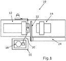
- FIG Fig. 1 An injection molding machine 10 is shown in a schematic plan view in FIG Fig. 1 shown.
- the injection molding machine 10 comprises two tool halves 12, 14, by means of which an injection molded part with an overmolded bush-like insert can be produced.
- the tool half 12 on the left according to the present illustration comprises a type of integrated feed mechanism by means of which the bush-like insert can be conveyed into the region of a cavity of the two tool halves 12, 14.
- the injection molding machine 10 can also include a supply periphery 16, which can have a vibrating pot 18 for storing and separating the socket-like insert parts.
- the feed periphery 16 can also have a hose 20 by means of which the separated inserts can be fed to the tool half 12, for example pneumatically.
- the entire supply periphery 16 can be designed to be mobile, that is to say can be provided on different injection molding machines 10 if required.
- the injection molding machine 10 can also have a linear handling 22 or a robot, by means of which the injection molded parts produced can be removed from the open tool halves 12, 14 and, for example, placed on a conveyor belt 24.
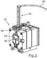
- FIG. 2 the tool half 12 is shown in a perspective view.
- a magazine 26 is connected to the upper side of the tool 12 and can be supplied with the socket-like insert parts via the hose 20 already mentioned.
- the supply of the inserts by means of the hose 20 is particularly advantageous when a large number of injection-molded parts are produced, that is to say the inserts are required continuously.
- the magazine 26 can be automatically filled with the inserts via the hose 20. In the case of smaller numbers of items, the magazine 26 can also be operated without a hose 20. In this case, the magazine 26 can be filled with the inserts, for example during downtimes.
- the socket-like insert parts can be sockets, flange sockets, threaded sockets, nuts or the like, for example.
- the socket-like insert parts can pass through the magazine 26 into the interior of the tool half 12 and from there can be arranged in the region of a mold insert 28 which forms at least part of a cavity 30 for the injection molded part.
- a separating device 34 is arranged in a lower region of the magazine 26. Above the separating device 34, a large number of the inserts can be stored in a row, one above the other.
- the separating device 34 can be driven pneumatically, for example, so that the separating device 34 can be moved up and down, whereby it can repeatedly release the insert located in the magazine 26 at the very bottom, so that it can individually move downward in the direction of the tool half 12 due to gravity .
- Fig. 3 the two tool halves 12, 14 are shown in a side sectional view in the closed state.
- the tool half 12 has a horizontally running conveying channel 36 which extends inside the tool half 12 and through the mold insert 28.
- the conveying channel 36 does not necessarily have to run purely horizontally.
- the latter comprises a feed channel 38 which extends in the vertical direction through the tool half 12 and opens into a receiving area 40 of the conveying channel 36.
- the mold half 12 comprises a positioning unit 42, which is designed to move from a demolding position shown here to an injection position to penetrate an opening of the relevant insert and thereby receive the relevant insert when it is arranged in the receiving area 40 of the conveying channel 36 , and to convey the inserted insert from the receiving area 40 to an injection molding position in the area of the mold insert 28.
- the inserts held by means of the magazine 26 can thus be fed to the vertically extending feed channel 38 singly and thus individually. Due to gravity, the inserts then individually fall through the feed channel 38 into the receiving area 40 of the conveying channel 36. There, the positioning unit can receive the respective insert and convey it from the receiving area 40 - according to the present illustration - to the left through the mold insert 28 to the said injection molding position . In this injection molding position, the insert 32 then protrudes so far into the cavity of the two tool halves 12, 14 that the insert 32 positioned in this way can be overmolded with plastic in the course of an injection molding process.
- the hose 20 can be connected to the tool half 12 in such a way that the inserts are fed in singly, for example via the hose 20 in the upper region of the feed channel 38, again for example by means of compressed air. It is also possible to feed the feed parts directly inside the tool half 12 by means of the hose 20, for example in a lower region of the feed channel 38 or above the receiving region 40.
- the tool half 12 comprises a core pull 46 for moving the positioning unit 42 between the demolding position shown here and the said injection position, which is then further to the left according to the present illustration.
- the core pull 46 can, for example, be hydraulically driven in order to move it to the left and right, as a result of which the positioning unit 42 can be moved back and forth between the demolding position shown here and the injection position further to the left.
- a wide variety of drive concepts are possible in order to move the core pull 46 and thus the positioning unit 42.
- FIG. 4 a section in the interior of the tool half 12, in which the positioning unit 42 (not shown here) is arranged, is shown.
- a lower part of the feed channel 38 running vertically in the tool half 12 can be seen, which opens into the receiving area 40 of the conveying channel 36, where a holding jaw 44 is arranged for receiving the insert 32, which can be seen here for the first time.
- the holding jaw 44 is arranged below the feed channel 38, specifically in the receiving area 40.
- the holding jaw 44 has a receiving contour for receiving the insert 32. This receiving contour can form a kind of negative contour of the insert 32 so that it can be reliably received by means of the holding jaw 44.
- the holding jaw 44 is acted upon by a restoring spring 48 with a restoring force.
- the present holding jaw 44 is in its fixing position.
- the restoring spring 48 exerts an upward restoring force on the holding jaw 44 and thereby presses it into the fixing position shown here.
- the holding jaw 44 ensures that the inserted insert 32 cannot be moved further to the left in the direction of the conveying channel 36, that is to say out of the receiving area 40.
- a front part of the positioning unit 42 is shown in a perspective view.
- the positioning unit 42 has a receiving pin 50 in its front area.
- This receiving pin 50 serves to receive the insert 32 arranged in the receiving area 40 and held by means of the holding jaw 44.
- the receiving pin 50 can, as shown in FIG Fig. 4 , coming from the right into an opening 52 of the insert 32.
- the receiving pin 50 can have a conically shaped tip.
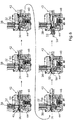
- a sequence of images is shown in which a movement of the receiving pin 50 through the receiving area 40 is shown, whereby the insert 32 initially received by the holding jaw 44 is received by the receiving pin 50 and the holding jaw 44 is pressed down by the positioning unit 42.
- the insert 32 first passes through the feed channel 38 due to gravity down into the receiving area 40 of the conveying channel 36, which extends through the mold insert 28 (see FIG. Fig. 3 ).
- the holding jaw 44 is arranged in its fixing position due to the force exerted by the return spring 48.
- the insert 32 thus falls into the receiving contour of the holding jaw 44 and is securely received and held by means of this, as can be seen in the upper middle figure in FIG Fig. 6 can recognize.
- a sensor which is not identified in any more detail here, it can be determined whether and when the insert 32 has arrived in the holding jaw 44 and is therefore located in an intended arrangement in the receiving area 40.
- the core pull 46 is actuated, as a result of which the positioning unit 42 together with the receiving pin 50 is moved from right to left in the direction of the receiving area 40.
- the receiving pin 50 then dips through the opening 52 of the insert 32, which is not identified here.
- the opening 52 is a through opening, but it can also be a blind hole, for example.
- the positioning unit 42 can have a magnet 54 (see Sect. Fig. 5 ), by means of which the inserted insert 32 can be securely held on the positioning unit 42.
- the holding jaw 44 can, for example, have a bevel, which is not identified here, along which the positioning unit 42 slides when it passes the holding jaw 44, as a result of which the holding jaw 44 is pressed down in the described manner.
- the insert 32 can then be arranged in the injection molding position by means of the positioning unit 42, that is to say in the region of the cavity 30 (see FIG. Fig. 3 ). At least a part of the insert 32 is arranged in the region of the cavity 30.
- the two tool halves 12, 14 are closed. After the mold halves 12, 14 have been closed, the cavity 30 of the mold insert 28 is filled with a plastic, as a result of which the plastic partially encapsulates the insert 32 arranged in the injection molding position. As a result, the said injection-molded part with the integrated insert 32 is produced.
- the tool half 12 can have a control, not shown here, which is designed to control the injection molding machine 10 in order to produce the said injection molded part.
- the controller can control both the feeding of the inserts 32 into the feed channel 38 and the movement or actuation of the positioning unit 42.
- the control of the tool half 12 can also control the injection molding machine 10 for producing the injection molded part, so that the two tool halves 12, 14 are closed and then the plastic is inserted into the cavity 30 is injected so that the respective insert 32 arranged in the injection molding position is encapsulated by plastic to form the injection molded part.
- Injection molding machines 10 of this type often already have a correspondingly suitable signal interface.
- the tool half 12 is therefore not tied to a machine and can be combined and used with various injection molding machines 10. If the tool half 12 has said control, the corresponding injection molding machines 10 can be cheaper, since they do not have to cover the functionality of the control of the tool half.
- Another advantage is that there is the possibility of being able to carry out a functional test, e.g. after maintenance, or tests without the injection molding machine 10 being required for this. Because the control can monitor the entire injection molding tool and thus also the tool half 12, one knows exactly where and what kind of problem or error there may be. This also simplifies the operation and monitoring of the injection molding machine.
- the tool half 12 itself does not have its own control.
- the injection molding machine 10 can have a controller. This can control both the feeding of the inserts 32 into the feed channel 38 and the movement or actuation of the positioning unit 42.
- a first embodiment of a locking unit 56 is shown, which is designed to lock the positioning unit 42 in its injection position, in which the insert 32 received by means of the positioning unit 42 is arranged in the injection molding position.
- the locking unit 56 has a type of claw 58 which can be slipped or moved over the positioning unit 42 in order to lock the positioning unit 42 in its movement. As a result, the positioning unit 42 can be locked against an injection pressure when the injection molding process is being carried out.
- a second embodiment of the locking unit 56 is shown.
- This can be operated hydraulically, for example, so that the locking unit 56 via a type of lateral link 60, for example, under a plate-shaped area of the positioning unit 42 and can thereby lock it.
- the positioning unit 42 can in turn be locked against an injection pressure when the injection molding process is being carried out.
- a recess 62 can be provided so that the link 60 does not have to travel too great a distance between a position locking the positioning unit 42 and a position releasing the positioning unit 42.
Landscapes
- Engineering & Computer Science (AREA)
- Manufacturing & Machinery (AREA)
- Mechanical Engineering (AREA)
- Moulds For Moulding Plastics Or The Like (AREA)
- Injection Moulding Of Plastics Or The Like (AREA)
Abstract
Description
- Die vorliegende Erfindung betrifft eine Werkzeughälfte und ein Verfahren zum Herstellen eines Spritzgussteils mit wenigstens einem buchsenartigen Einlegeteil.
- Es ist an sich bekannt, bei Spritzgussteilen Einlegeteile, beispielsweise in Form von Buchsen, Bundbuchsen, Gewindebuchsen, Muttern und dergleichen zu integrieren. Dafür werden solche Einlegeteile im Bereich einer Kavität eines Spritzgusswerkzeugs angeordnet und mit einem Kunststoff zumindest teilweise umspritzt. Das Handling und die Positionierung solcher Einlegeteile im Bereich einer Kavität eines Spritzgusswerkzeugs kann sich mitunter relativ aufwendig gestalten. Dies kann mit einer aufwendigen und kostenintensiven Peripherie, langen Zykluszeiten und einem relativ hohen Platzbedarf bei einer Spritzgussmaschine miteinhergehen.
- Es ist daher die Aufgabe der vorliegenden Erfindung, eine Lösung bereitzustellen, mittels welcher ein Spritzgussteil mit wenigstens einem integrierten buchsenartigen Einlegeteil besonders einfach hergestellt werden kann.
- Diese Aufgabe wird durch eine Werkzeughälfte für eine Spritzgussmaschine sowie durch ein Verfahren zum Herstellen eines Spritzgussteils mit den Merkmalen der unabhängigen Ansprüche gelöst. Weitere mögliche Ausgestaltungen der Erfindung sind insbesondere in den abhängigen Ansprüchen angegeben.
- Die erfindungsgemäße Werkzeughälfte für eine Spritzgussmaschine zum Herstellen eines Spritzgussteils mit wenigstens einem buchsenartigen Einlegeteil umfasst einen Formbereich, der zumindest einen Teil einer Kavität für das Spritzgussteil bildet. Des Weiteren umfasst die Werkzeughälfte einen sich im Inneren der Werkzeughälfte und durch den Formbereich hindurch ersteckenden Beförderungskanal. Zudem umfasst die Werkzeughälfte ein zum Zuführen des Einlegeteils in die Werkzeughälfte ausgelegten Zuführkanal, der sich in vertikaler Richtung durch die Werkzeughälfte erstreckt und in einen Aufnahmebereich des Beförderungskanals mündet. Zudem weist die Werkzeughälfte eine Positioniereinheit auf, die dazu ausgelegt ist, durch eine Bewegung von einer Entformposition in eine Spritzposition in eine Öffnung des Einlegeteils einzudringen und dadurch das Einlegeteil aufzunehmen, wenn dieses im Aufnahmebereich des Beförderungskanals angeordnet ist, und das aufgenommene Einlegeteil vom Aufnahmebereich zu einer Spritzgussposition im Bereich des Formbereichs zu befördern.
- Die erfindungsgemäße Werkzeughälfte umfasst also eine Art integrierte Zuführmechanik, um wenigstens ein buchsenartiges Einlegeteil im Bereich einer Kavität in einer vorgegebenen Spritzgussposition anzuordnen, sodass das Einlegeteil nach dem Schließen eines Spritzgusswerkzeugs, welches die erfindungsgemäße Werkzeughälfte umfasst, umspritzt werden kann. Bei dem Formbereich kann es sich um ein separates Bauteil, z.B. einen Formeinsatz, handeln, es ist aber genauso gut möglich, dass der Formbereich kein separates Bauteil ist, sondern z.B. in eine Formplatte eingearbeitet ist. Der Formbereich weist eine oder mehrere Vertiefungen auf, welche eine Negativform für das Spritzgussteil bilden.
- Unter buchsenartigem Einlegeteil ist zu verstehen, dass das Einlegeteil eine Öffnung aufweist, welche einen runden oder auch beispielsweise einen eckigen Querschnitt aufweisen kann. Insbesondere kann sich die Öffnung in Längsrichtung des Einlegeteils erstrecken. Bei dem buchsenartigen Einlegeteil kann es sich beispielsweise um eine Buchse, eine Bundbuchse, eine Gewindebuchse, eine Mutter oder dergleichen handeln. Mittels der erfindungsgemäßen Werkzeughälfte ist es also möglich, ein solches buchsenartiges Einlegeteil auf ganz einfache Weise im Bereich der Kavität der Werkzeughälfte zu positionieren.
- Durch den Zuführkanal ist es möglich, das buchsenartige Einlegeteil ins Innere der Werkzeughälfte zuzuführen. Dadurch, dass sich der Zuführkanal in vertikaler Richtung durch die Werkzeughälfte erstreckt, sind keine Fördermittel oder dergleichen erforderlich, um das Einlegeteil im Inneren der Werkzeughälfte bis zum Beförderungskanal fortzubewegen. Der Zuführkanal kann auch schräg verlaufen, muss also nicht rein in vertikaler Richtung verlaufen. Wesentlich beim Zuführkanal ist jedoch, dass dieser so verläuft, dass das buchsenartige Einlegeteil rein schwerkraftbedingt durch den Zuführkanal zum Aufnahmebereich des Beförderungskanals gelangen kann.
- Mittels der Positioniereinheit ist es möglich, das im Aufnahmebereich angeordnete buchsenartige Einlegeteil bis zur Spritzgussposition im Bereich des Formbereichs, also in den Bereich der Kavität, zu befördern. Dafür kann die Positioniereinheit zwischen der besagten Entformposition und der besagten Spritzgussposition insbesondere translatorisch hin und her bewegt werden. Die Positioniereinheit ist dabei so gestaltet, dass sie in die Öffnung des Einlegeteils eindringen und dadurch das Einlegeteil aufnehmen kann, wenn das Einlegeteil im Aufnahmebereich des Beförderungskanals angeordnet ist. Nachdem das Einlegeteil im Aufnahmebereich des Beförderungskanals angekommen ist, muss die Positioniereinheit also nur von der Entformposition in die Spritzposition bewegt werden, in Folge dessen die Positioniereinheit unter anderem auch den Aufnahmebereich des Beförderungskanals passiert, wo die Positioniereinheit in die Öffnung des Einlegeteils gelangt und dieses dadurch ergreift beziehungsweise aufnimmt. Durch weitere Fortbewegung der Positioniereinheit bis zur Spritzposition kann das Einlegeteil in seine Spritzgussposition im Bereich des Formbereichs befördert werden.
- Bei der erfindungsgemäßen Werkzeughälfte ist es also nicht mehr erforderlich, eine kostenintensive Peripherie vorzusehen, um das buchsenartige Einlegeteil in seiner Spritzgussposition im Bereich des Formbereichs anzuordnen. Durch die Integration der Positioniereinheit in die Werkzeughälfte ergibt sich eine besonders platzsparende Zuführmechanik, mittels welcher das buchsenartige Einlegeteil im Inneren der Werkzeughälfte bis zur Spritzgussposition im Bereich des Formbereichs befördert werden kann. Bei der erfindungsgemäßen Werkzeughälfte ist es mit sehr kurzen Zykluszeiten möglich, das besagte Spritzgussteil mit dem integrierten Einlegeteil herzustellen.
- Zudem ist es mittels der erfindungsgemäßen Werkzeughälfte auch möglich, Spritzgussteile herzustellen, bei welchen das buchsenartige Einlegeteil nicht mit umspritzt wird. Die Positioniereinheit kann beispielsweise so gestaltet sein, dass mittels dieser der Formbereich bei Bedarf - also wenn kein Einlegeteil mit umspritzt werden soll - dicht abgeschlossen werden kann. So ist es möglich, mittels der Werkzeughälfte auch Spritzgussteile herzustellen, bei denen kein Einlegeteil mit umspritzt werden soll.
- Durch die integrierte Positioniereinheit ist es darüber hinaus möglich, derartige buchsenartige Einlegeteile besonders zuverlässig immer wieder passgenau an der besagten Spritzgussposition im Bereich des Formbereichs zu positionieren. Es sind beispielsweise keine Handlingroboter oder dergleichen notwendig, um das buchsenartige Einlegeteil in der Spritzgussposition im Bereich des Formbereichs anzuordnen.
- Eine Steuerung und Überwachung sämtlicher Funktionen der Werkzeughälfte und auch der Spritzgussmaschine kann von der Werkzeughälfte selbst übernommen werden. Zudem ist es möglich, eine Bestückung mit einer Vielzahl solcher buchsenartiger Einlegeteile zum Beispiel in Nebenzeiten der Spritzgussmaschine vorzunehmen. Eine Zuführung und Bereitstellung der buchsenartigen Einlegeteile kann auf unterschiedlichste Weise erfolgen. Beispielsweise ist es möglich, ein Stangenmagazin oder auch ein Trommelmagazin vorzusehen, welches an den Zuführkanal angeschlossen werden kann. Die Anordnung solcher Magazine kann beispielsweise oben an der Werkzeughälfte oder auch seitlich erfolgen. Auch kann beispielsweise eine pneumatische Zuführeinheit verwendet werden, welche zum Beispiel über einen Schlauch direkt mit der Werkzeughälfte und somit mit Zuführkanal verbunden ist.
- Eine mögliche Ausgestaltung der Erfindung sieht vor, dass die Werkzeughälfte einen Kernzug zum Bewegen der Positioniereinheit zwischen der Entformposition und der Spritzposition aufweist. Die Positioniereinheit weist zudem einen im Beförderungskanal angeordneten und mit dem Kernzug verbundene Positionierstift auf. Beim Bewegen der Positioniereinheit von der Entformposition in die Spritzposition wird der Positionierstift innerhalb des Beförderungskanals in Richtung des Formbereichs bewegt. Auf dem Weg von der Entformposition in die Spritzposition passiert der Positionierstift den Aufnahmebereich, und kann dadurch in die Öffnung des Einlegeteils eindringen und dieses aufnehmen, wenn das Einlegeteil im Aufnahmebereich angeordnet ist. Durch weitere Bewegung der Positioniereinheit über den Aufnahmebereich hinaus bis zur Entformposition kann das aufgenommene Einlegeteil in die Spritzgussposition befördert werden. Es ist beispielsweise auch möglich, mehrere solcher Positionierstifte an dem Kernzug vorzusehen. Mittels des besagten Positionierstifts ist es auf einfache und zuverlässige Weise möglich, in die Öffnung des Einlegeteils einzudringen, wenn das Einlegeteil im Aufnahmebereich des Beförderungskanals angeordnet ist. Durch eine translatorische Bewegung des Positionierstifts in Richtung des Formbereichs dringt dieser in die Öffnung des Einlegeteils ein, wenn dieser den Aufnahmebereich passiert. Durch weitere Bewegung des Positionierstifts in Richtung der Kavität kann das Einlegeteil dann bis zur Spritzgussposition befördert werden.
- Eine weitere mögliche Ausgestaltung der Erfindung sieht vor, dass im Bereich des Positionierstifts ein Magnet zum Fixieren des mittels des Positionierstifts aufgenommenen Einlegeteils angeordnet ist. Dadurch kann nach dem Eindringen des Positionierstifts in die Öffnung des Einlegeteils auf zuverlässige Weise sichergestellt werden, dass das einmal mittels des Positionierstifts aufgenommene Einlegeteil auch sicher mittels des Positionierstifts gehalten werden kann, insbesondere bis das Einlegeteil unter Vermittlung der Positionierhülse und der Positioniereinheit in die Spritzgussposition befördert wurde.
- Gemäß einer weiteren möglichen Ausgestaltung der Erfindung ist es vorgesehen, dass die Werkzeughälfte eine zwischen einer Fixierstellung und Freigabestellung bewegbare Haltebacke aufweist, die zum Aufnehmen des Einlegeteils unterhalb vom Zuführkanal angeordnet ist. Die Haltebacke ragt in der Fixierstellung so weit in den Beförderungskanal hinein, dass diese eine Bewegung des im Aufnahmebereich angeordneten Einlegeteils in Richtung des Formbereichs blockiert. Die Haltebacke ist in der Freigabestellung soweit aus dem Beförderungskanal herausbewegt, dass diese eine Bewegung der Positioniereinheit mitsamt dem durch diese aufgenommenen Einlegeteil in Richtung des Formbereichs freigibt. Die Haltebacke weist einen Aufnahmebereich auf, der auf die Außenkontur des Einlegeteils abgestimmt ist. Die Haltebacke weist also eine Kontur auf, welche beispielsweise einem Negativ von einem Teilbereich des Einlegeteils entspricht. Fällt das Einlegeteil schwerkraftbedingt durch den Zuführkanal in den Aufnahmebereich herunter, so gelangt dieses in die Haltebacke und wird darin zuverlässig gehalten. Solange sich die Haltebacke in ihrer Fixierstellung befindet, kann das aufgenommene Einlegeteil nicht in Längsrichtung des Beförderungskanals bewegt werden. Die Positioniereinrichtung kann dadurch problemlos in Richtung des Einlegeteils bewegt werden und so in die Öffnung des Einlegeteils eintauchen, um das Einlegeteil aufzunehmen. Nachdem das Einlegeteil mittels der Positioniereinrichtung aufgenommen wurde, kann diese weiter in Richtung der Spritzposition bewegt werden. Dabei sind die Haltebacke und die Positioniereinheit geometrisch so aufeinander abgestimmt, dass die Positioniereinheit beim Passieren der Haltebacke diese von ihrer Fixierstellung in die Freigabestellung herunterdrückt. Dadurch kann die Positioniereinheit mitsamt dem aufgenommenen Einlegeteil die Haltebacke passieren und das Einlegeteil in der Spritzgussposition im Bereich der Kavität des Formbereichs positionieren.
- In weiterer möglicher Ausgestaltung der Erfindung ist es vorgesehen, dass eine Rückstellfeder eine Rückstellkraft in Richtung der Fixierstellung auf die Haltebacke ausübt und die Positioniereinheit die Haltebacke beim Passieren des Aufnahmebereichs in die Freigabestellung drückt. Die Rückstellfeder sorgt dafür, dass im ansonsten unbelasteten Zustand die Haltebacke immer automatisch in ihrer Fixierstellung angeordnet ist. Erst wenn auf die Haltebacke eine Kraft aufbracht wird, die groß genug ist, die von der Rückstellfeder aufgebrachte Rückstellkraft zu überwinden, wird die Haltebacke in ihre Freigabestellung bewegt. Die Positioniereinheit und die Haltebacke weisen eine jeweilige derart aufeinander abgestimmte Form auf, dass die Positioniereinheit die Haltebacke beim Passieren des Aufnahmebereichs in die Freigabestellung drückt. Die Formgebung der Positioniereinheit und der Haltebacke sind so aufeinander abgestimmt, dass die Positioniereinheit die Haltebacke erst dann in die Freigabestellung drückt, wenn das Einlegeteil bereits zuverlässig mittels der Positioniereinheit von der Haltebacke aufgenommen wurde. Im aufeinander abgestimmten Zusammenspiel zwischen der Positioniereinheit der Haltebacke kann also jederzeit zuverlässig sichergestellt werden, dass das Einlegeteil zunächst sicher von der Haltebacke aufgefangen werden kann, wenn das Einlegeteil durch den Zuführkanal schwerkraftbedingt in den Aufnahmebereich fällt. Zudem kann durch die Haltebacke sichergestellt werden, dass das aufgenommene Einlegeteil sich nicht verschiebt, während die Positioniereinheit durch die Öffnung des Einlegeteils geschoben wird, während das Einlegeteil mittels der Haltebacke aufgenommen ist. Erst wenn das Einlegeteil zuverlässig mittels der Positioniereinheit aufgenommen wird, drückt die Positioniereinheit bei weiterer Bewegung in Richtung des Formbereichs die Haltebacke in ihre Freigabestellung herunter, sodass die Positioniereinheit die Haltebacke passieren kann.
- Eine weitere mögliche Ausgestaltung der Erfindung sieht vor, dass die Haltebacke eine Schräge aufweist, entlang welcher die Positioniereinheit beim Passieren des Aufnahmebereichs entlanggleitet und dadurch die Haltebacke von der Fixierstellung in die Freigabestellung drückt. Auf diese Weise kann ganz einfach sichergestellt werden, dass beim Passieren der Haltebacke die Positioniereinheit die Haltebacke erst dann in die Freigabestellung drückt, wenn die Positioniereinheit das Einlegeteil sicher aufgenommen hat. Die Positioniereinheit kann eine entsprechende Kontur aufweisen, welche entlang der besagten Schräge der Haltebacke entlanggleiten und somit die Haltebacke nach unten drücken kann. Es ist auch möglich, dass an der Positioniereinheit eine Schräge vorgesehen ist, welche beim Entlanggleiten an der Haltebacke diese in die Freigabestellung drückt.
- In weiterer möglicher Ausgestaltung der Erfindung ist es vorgesehen, dass die Werkzeughälfte eine Verriegelungseinheit aufweist, welche dazu ausgelegt ist, die Positioniereinheit in ihrer Spritzposition zu verriegeln, in der das mittels des Positioniereinheit aufgenommene Einlegeteil in der Spritzgussposition angeordnet ist. Die Verriegelungseinheit kann beispielsweise über eine Art Klaue verfügen, welche so ausgefahren werden kann, dass diese eine Bewegung der Positioniereinheit sperrt. Auch ist es beispielsweise möglich, dass der besagte Kernzug und die Positioniereinheit mittels eines hydraulischen Zylinders bewegbar sind, wobei der hydraulische Zylinder über besagte Verriegelungseinheit verriegelt werden kann. Die Verriegelungseinheit kann auch beispielsweise über eine Art seitliche Kulisse für die Verriegelung der Positioniereinheit sorgen. Mittels der Verriegelungseinheit kann sichergestellt werden, dass die Positioniereinheit in ihrer Spritzposition verriegelt wird. Beim Spritzgussvorgang herrschen mitunter sehr hohe Drücke, sodass durch Verriegeln der Positioniereinheit in ihrer Spritzposition sichergestellt werden kann, dass weder die Positioniereinheit noch das mittels der Positioniereinheit aufgenommene Einlegeteil in unerwünschter Weise durch den Spritzdruck verschoben beziehungsweise bewegt werden.
- In weiterer möglicher Ausgestaltung der Erfindung ist es vorgesehen, dass die Werkzeughälfte eine Sensorik aufweist, welche dazu ausgelegt ist, eine Position des Einlegeteils und/oder der Positioniereinheit zu ermitteln und entsprechende Positionssignale an eine Steuerung der Werkzeughälfte zu übermitteln. Die Steuerung ist dazu eingerichtet, in Abhängigkeit von den Sensorsignalen die Positioniereinheit zum Befördern des Einlegeteils in die Spritzgussposition anzusteuern. Die Positioniereinheit muss vor dem Zuführen des Einlegeteils in der Entformposition angeordnet sein. Dies kann mittels der Sensorik überprüft werden, welche dafür beispielsweise Näherungsschalter aufweisen kann. Mittels der Sensorik kann zudem auch überprüft werden, ob das Einlegeteil korrekt in dem Aufnahmebereich angeordnet wurde. Die Sensorik kann beispielsweise auch dazu ausgelegt sein, zu überprüfen, ob die Positioniereinheit in ihrer Spritzposition angeordnet ist und/oder ob das Einlegeteil in der vorgegebenen Spritzgussposition im Bereich des Formbereichs angeordnet ist. Die Spritzposition der Positioniereinheit kann dabei einer Endlage der Positioniereinheit entsprechen. Diese Endlage der Positioniereinheit kann beispielsweise mittels Endschaltern, welche Teil der Sensorik sein können, abgefragt werden. Die Steuerung ist dazu eingerichtet, jeweilige Sensorsignale der Sensorik auszuwerten und dadurch zu überprüfen, ob das Einlegeteil während des Zuführvorgangs beziehungsweise Beförderungsvorgangs des Einlegeteils bis zur Spritzgussposition immer entsprechend richtig angeordnet ist. Dadurch kann ein besonders zuverlässiger Zuführprozess des Einlegeteils bis zur Spritzgussposition sichergestellt werden. Durch die integrierte Steuerung der Werkzeughälfte, kann die Werkzeughälfte sämtliche die Zuführung und Positionierung des Einlegeteils betreffenden Aktionen selbst steuern. Die Spritzgussmaschine, bei der die Werkzeughälfte eingesetzt bzw. verbaut wird, muss selbst also keine Steuerung aufweisen, welche die Positioniereinheit ansteuern kann. Die Werkzeughälfte kann dadurch auch ganz einfach an unterschiedlichen Spritzgussmaschinen verbaut werden, ohne dass aufwendige Umrüstmaßnahmen an der betreffenden Spritzgussmaschine im Hinblick auf die Steuerung notwendig werden.
- Eine weitere mögliche Ausgestaltung der Erfindung sieht vor, dass die Steuerung dazu eingerichtet ist, eine Zuführvorrichtung, welche dazu ausgelegt ist, eine Vielzahl der Einlegeteile zu vereinzeln und dem Zuführkanal zuzuführen, zum Zuführen des Einlegeteils in den Aufnahmebereich des Beförderungskanals in Abhängigkeit von den Sensorsignalen anzusteuern. So kann die Sensorik beispielsweise überprüfen, ob die Positioniereinheit in ihrer Entformposition angeordnet ist. Falls dies der Fall sein sollte, kann die Steuerung wiederum die Zuführvorrichtung so ansteuern, dass diese eines der Einlegeteile vereinzelt und dem Zuführkanal zuführt, sodass das jeweilige Einlegeteil schwerkraftbedingt bis zum Aufnahmebereich des Beförderungskanals gelangen kann. Bei der Zuführvorrichtung kann es sich beispielsweise um ein Magazin handeln, das an der Werkzeughälfte angebracht werden kann, um für jeweilige Spritzgussvorgänge jeweilige Einlegeteile zu vereinzeln und dem Zuführkanal zuführen. Auch kann es sich um ein Peripheriegerät bei der Zuführvorrichtung handeln, welches beispielsweise über einen Rütteltopf verfügt, von wo aus zum Beispiel pneumatisch über einen Schlauch die Einlegeteile bis zur Werkzeughälfte und somit zum Zuführkanal befördert werden können. Die Werkzeughälfte kann also über ihre eigene Steuerung unter Berücksichtigung der Sensorsignale eine solche Zuführvorrichtung ansteuern.
- Gemäß einer weiteren möglichen Ausgestaltung der Erfindung ist es vorgesehen, dass die Steuerung dazu eingerichtet ist, die Spritzgussmaschine zum Herstellen des Spritzgussteils anzusteuern, wenn die Steuerung anhand der Sensorsignale ermittelt hat, dass das Einlegeteil in der Spritzgussposition angeordnet ist. Die Werkzeughälfte selbst kann also über ihre integrierte Steuerung die Spritzgussmaschine ansteuern, in welcher die Werkzeughälfte verbaut ist. Sobald anhand der Sensorsignale ermittelt wurde, dass das Einlegeteil sich in der Spritzgussposition befindet, kann die Steuerung die Spritzgussmaschine so ansteuern, dass ein die Werkzeughälfte umfassendes Spritzgusswerkzeug der Spritzgussmaschine geschlossen, anschließend ein Kunststoff in die Kavität gespritzt und dadurch das in der Spritzgussposition angeordnete Einlegeteil unter Ausbildung des Spritzgussteils vom Kunststoff umspritzt wird.
- Bei dem erfindungsgemäßen Verfahren zum Herstellen eines Spritzgussteils mit wenigstens einem buchsenartigen Einlegeteil wird die erfindungsgemäße Werkzeughälfte oder eine mögliche Ausgestaltung der Werkzeughälfte verwendet, wobei zunächst das Einlegeteil in den Zuführkanal zugeführt wird, wonach das Einlegeteil schwerkraftbedingt in den Aufnahmebereich des Beförderungskanals gelangt. Danach wird die Positioniereinheit von der Entformposition bis zur Spritzposition bewegt, infolgedessen die Positioniereinheit in eine Öffnung des im Aufnahmebereich angeordneten Einlegeteils eindringt und dieses aufnimmt sowie bis zur Spritzgussposition im Bereich des Formbereichs befördert. Danach wird eine Spritzgussmaschine zum Herstellen des Spritzgussteils mittels einer Steuerung der Werkzeughälfte angesteuert, und zwar so, dass ein die Werkzeughälfte umfassendes Spritzgusswerkzeug der Spritzgussmaschine geschlossen, ein Kunststoff in die Kavität gespritzt und das in der Spritzgussposition angeordnete Einlegeteil unter Ausbildung des Spritzgussteils vom Kunststoff umspritzt wird. Die erläuterten möglichen Ausgestaltungen der Werkzeughälfte sind als mögliche Ausgestaltungen des Verfahrens und umgekehrt anzusehen, wobei die Werkzeughälfte insbesondere Mittel zur Durchführung der Verfahrensschritte aufweist.
- Weitere Vorteile, Merkmale und Einzelheiten der Erfindung können sich aus der nachfolgenden Beschreibung möglicher Ausführungsbeispiele sowie anhand der Zeichnung ergeben. Die vorstehend in der Beschreibung genannten Merkmale und Merkmalskombinationen sowie die nachfolgend in der Figurenbeschreibung und/oder in den Figuren alleine gezeigten Merkmale und Merkmalskombinationen sind nicht nur in der jeweils angegebenen Kombination, sondern auch in anderen Kombinationen oder in Alleinstellung verwendbar, ohne den Rahmen der Erfindung zu verlassen.
- Die Zeichnung zeigt in:
- Fig. 1
- eine schematische Draufsicht auf eine Spritzgussmaschine, die zwei Werkzeughälften aufweist, mittels welchen ein Spritzgussteil mit wenigstens einem buchsenartigen Einlegeteil hergestellt werden kann, wobei eine der beiden Werkzeughälften eine Art integrierten Zuführmechanismus zum Zuführen des buchsenartigen Einlegeteils in eine Spritzgussposition aufweist;
- Fig. 2
- eine Perspektivansicht der Werkzeughälfte mit dem integrierten Zuführmechanismus, wobei oberseitig an der Werkzeughälfte ein Magazin zum Bereitstellen und Vereinzeln einer Vielzahl der Einlegeteile angebracht ist;
- Fig. 3
- eine seitliche Schnittansicht der beiden Werkzeughälften im geschlossenen Zustand, wobei sich im Inneren der einen Werkzeughälfte eine Positioniereinheit befindet, welche dazu dient, die buchsenartigen Einlegeteile im Bereich eines Formeinsatzes zu positionieren;
- Fig. 4
- eine perspektivische Detailansicht von einem Ausschnitt im Inneren der Werkzeughälfte, in der die Positioniereinheit angeordnet ist, wobei ein Teil eines vertikal in der Werkzeughälfte verlaufenden Zuführkanals zu erkennen ist, der in einen Aufnahmebereich mündet, wo eine Haltebacke zum Aufnehmen des Einlegeteils angeordnet ist;
- Fig. 5
- eine Perspektivansicht eines vorderen Teils der Positioniereinheit, welche einen Aufnahmestift aufweist, welcher zum Aufnehmen der Einlegeteile dient;
- Fig. 6
- eine Abfolge von Abbildungen, in denen eine Bewegung des Aufnahmestifts durch den Aufnahmebereich dargestellt wird, wodurch das zunächst mittels der Haltebacke aufgenommene Einlegeteil mittels des Aufnahmestifts aufgenommen und die Haltebacke durch die Positioniereinheit nach unten gedrückt wird;
- Fig. 7
- eine Perspektivansicht einer ersten Ausführungsform einer Verriegelungseinheit, mittels welcher die Positioniereinheit verriegelt werden kann;
- Fig. 8
- eine Perspektivansicht einer zweiten Ausführungsform der Verriegelungseinheit;
- In den Figuren sind gleiche oder funktionsgleiche Elemente mit den gleichen Bezugszeichen versehen worden.
- Eine Spritzgussmaschine 10 ist in einer schematischen Draufsicht in
Fig. 1 gezeigt. Die Spritzgussmaschine 10 umfasst zwei Werkzeughälften 12, 14, mittels welchen ein Spritzgussteil mit einem umspritzten buchsenartigen Einlegeteil hergestellt werden kann. Die gemäß der vorliegenden Darstellung linke Werkzeughälfte 12 umfasst eine Art integrierte Zuführmechanik, mittels welcher das buchsenartige Einlegeteil in den Bereich einer Kavität der beiden Werkzeughälften 12, 14 befördert werden kann. Zur Spritzgussmaschine 10 kann noch eine Zuführperipherie 16 gehören, welche einen Rütteltopf 18 zum Bevorraten und Vereinzeln der buchsenartigen Einlegeteile aufweisen kann. Die Zuführperipherie 16 kann zudem einen Schlauch 20 aufweisen, mittels welchem beispielsweise pneumatisch die vereinzelten Einlegeteile der Werkzeughälfte 12 zugeführt werden können. Die gesamte Zuführperipherie 16 kann mobil ausgestaltet sein, kann also bei Bedarf an unterschiedlichen Spritzgussmaschinen 10 bereitgestellt werden. Die Spritzgussmaschine 10 kann darüber hinaus über ein Linearhandling 22 beziehungsweise einen Roboter verfügen, mittels welchem die hergestellten Spritzgussteile aus den geöffneten Werkzeughälften 12, 14 entnommen und zum Beispiel auf einem Förderband 24 abgelegt werden können. - In
Fig. 2 ist die Werkzeughälfte 12 in einer Perspektivansicht gezeigt. Oberseitig am Werkzeug 12 ist ein Magazin 26 angeschlossen, das über den bereits erwähnten Schlauch 20 mit den buchsenartigen Einlegeteilen versorgt werden kann. Die Zuführung der Einlegeteile mittels des Schlauchs 20 ist insbesondere dann von Vorteil, wenn sehr viele Spritzgussteile hergestellt werden, also fortlaufend die Einlegeteile benötigt werden. Über den Schlauch 20 kann das Magazin 26 automatisch mit den Einlegeteilen befüllt werden. Bei geringeren Stückzahlen kann auch das Magazin 26 ohne Schlauch 20 betrieben werden. In dem Fall kann das Magazin 26 beispielsweise während Stillstandszeiten mit den Einlegeteilen befüllt werden. - Bei den buchsenartigen Einlegeteilen kann es sich beispielsweise um Buchsen, Bundbuchsen, Gewindebuchsen, Muttern oder dergleichen handeln. Durch das Magazin 26 können die buchsenartigen Einlegeteile ins Innere der Werkzeughälfte 12 gelangen und von dort aus im Bereich eines Formeinsatzes 28, der zumindest einen Teil einer Kavität 30 für das Spritzgussteil bildet, angeordnet werden. In einem unteren Bereich des Magazins 26 ist eine Vereinzelungsvorrichtung 34 angeordnet. Oberhalb von der Vereinzelungsvorrichtung 34 kann eine Vielzahl der Einlegeteile in einer Reihe übereinander angeordnet bevorratet werden. Die Vereinzelungsvorrichtung 34 kann beispielsweise pneumatisch angetrieben werden, sodass die Vereinzelungsvorrichtung 34 auf und ab bewegt werden kann, wobei diese dabei immer wieder das im Magazin 26 gerade ganz unten angeordnete Einlegeteil freigeben kann, sodass dieses einzeln schwerkraftbedingt nach unten in Richtung der Werkzeughälfte 12 gelangen kann.
- In
Fig. 3 sind die beiden Werkzeughälften 12, 14 in einer Seitenschnittansicht im geschlossenen Zustand gezeigt. Die Werkzeughälfte 12 weist einen horizontal verlaufenden Beförderungskanal 36 auf, der sich im Inneren der Werkzeughälfte 12 und durch den Formeinsatz 28 hindurch erstreckt. Der Beförderungskanal 36 muss aber nicht unbedingt rein horizontal verlaufen. - Zum Zuführen der hier nicht dargestellten Einlegeteile ins Innere der Werkzeughälfte 12 umfasst diese einen Zuführkanal 38, der sich in vertikaler Richtung durch die Werkzeughälfte 12 erstreckt und in einen Aufnahmebereich 40 des Beförderungskanals 36 mündet. Des Weiteren umfasst die Werkzeughälfte 12 eine Positioniereinheit 42, die dazu ausgelegt ist, durch eine Bewegung von einer hier gezeigten Entformposition in eine Spritzposition in eine Öffnung des betreffenden Einlegeteils einzudringen und dadurch das betreffende Einlegeteil aufzunehmen, wenn dieses im Aufnahmebereich 40 des Beförderungskanals 36 angeordnet ist, und das aufgenommene Einlegeteil vom Aufnahmebereich 40 bis zu einer Spritzgussposition im Bereich des Formeinsatzes 28 zu befördern.
- Die mittels des Magazins 26 vorgehaltenen Einlegeteile können also vereinzelt und somit einzeln dem sich vertikal erstreckenden Zuführkanal 38 zugeführt werden. Schwerkraftbedingt fallen die Einlegeteile dann einzeln durch den Zuführkanal 38 in den Aufnahmebereich 40 des Beförderungskanals 36. Dort kann die Positioniereinheit das jeweilige Einlegeteil aufnehmen und dieses vom Aufnahmebereich 40 - gemäß der vorliegenden Darstellung - nach links durch den Formeinsatz 28 hindurch bis zu der besagten Spritzgussposition befördern. In dieser Spritzgussposition ragt das Einlegeteil 32 dann so weit in die Kavität der beiden Werkzeughälften 12, 14 hinein, dass im Zuge eines Spritzgussvorgangs das so positionierte Einlegeteil 32 mit Kunststoff umspritzt werden kann.
- Abweichend von der Darstellung in
Fig. 2 ist es auch möglich, das Magazin 26 wegzulassen. In dem Fall kann der Schlauch 20 so an der Werkzeughälfte 12 angeschlossen werden, dass die Einlegeteile z.B. über den Schlauch 20 im oberen Bereich des Zuführkanals 38 vereinzelt zugeführt werden, wiederum beispielsweise mittels Druckluft. Auch ist es möglich, die Zuführteile mittels des Schlauchs 20 direkt im Inneren der Werkzeughälfte 12 zuzuführen, beispielsweise in einem unteren Bereich des Zuführkanals 38 bzw. oberhalb vom Aufnahmebereich 40. - Die Werkzeughälfte 12 umfasst einen Kernzug 46 zum Bewegen der Positioniereinheit 42 zwischen der hier gezeigten Entformposition und der besagten Spritzposition, welche sich gemäß der vorliegenden Darstellung dann weiter links befindet. Der Kernzug 46 kann beispielsweise hydraulisch angetrieben werden, um diesen nach links und rechts zu bewegen, in Folge dessen die Positioniereinheit 42 entsprechend zwischen der hier gezeigten Entformposition und der weiter links befindlichen Spritzposition hin und her bewegt werden kann. Es sind verschiedenste Antriebskonzepte möglich, um den Kernzug 46 und somit die Positioniereinheit 42 zu bewegen.
- In
Fig. 4 ist ein Ausschnitt im Inneren der Werkzeughälfte 12, in der die hier nicht dargestellte Positioniereinheit 42 angeordnet ist gezeigt. Ein unterer Teil des vertikal in der Werkzeughälfte 12 verlaufenden Zuführkanals 38 ist zu erkennen ist, der in den Aufnahmebereich 40 der Beförderungskanals 36 mündet, wo eine Haltebacke 44 zum Aufnehmen des hier erstmals zu erkennenden Einlegeteils 32 angeordnet ist. Die Haltebacke 44 ist unterhalb vom Zuführkanal 38 angeordnet, und zwar im Aufnahmebereich 40. Wenn das Einlegeteil 32 schwerkraftbedingt in den Aufnahmebereich 40 fällt, fängt die Haltebacke 44 also das Einlegeteil 32 auf. Die Haltebacke 44 weist eine Aufnahmekontur zum Aufnehmen des Einlegeteils 32 auf. Diese Aufnahmekontur kann eine Art Negativkontur des Einlegeteils 32 bilden, sodass dieses zuverlässig mittels der Haltebacke 44 aufgenommen werden kann. - Die Haltebacke 44 wird von einer Rückstellfeder 48 mit einer Rückstellkraft beaufschlagt. Vorliegende befindet sich die Haltebacke 44 in ihrer Fixierstellung. Die Rückstellfeder 48 übt gemäß der vorliegenden Darstellung eine Rückstellkraft nach oben auf die Haltebacke 44 aus und drückt diese dadurch in die hier gezeigte Fixierstellung. In dieser Fixierstellung sorgt die Haltebacke 44 dafür, dass das aufgenommen Einlegeteil 32 nicht in Richtung des Beförderungskanals 36 weiter nach links, also aus dem Aufnahmebereich 40 heraus bewegt werden kann.
- In
Fig. 5 ist ein vorderer Teil der Positioniereinheit 42 in einer Perspektivansicht gezeigt. Die Positioniereinheit 42 weist in ihrem vorderen Bereich einen Aufnahmestift 50 auf. Dieser Aufnahmestift 50 dient dazu, das im Aufnahmebereich 40 angeordneten und mittels der Haltebacke 44 gehaltene Einlegeteil 32 aufzunehmen. Der Aufnahmestift 50 kann, gemäß der Darstellung inFig. 4 , von rechts kommend in eine Öffnung 52 des Einlegeteils 32 eingeführt werden. Um das Einführen in die Öffnung 52 zu erleichtern kann der Aufnahmestift 50 eine konische geformte Spitze aufweisen. Durch entsprechende Bewegung des Kernzugs 46 (s.Fig. 3 ) von der Entformposition in die Spritzposition wird der Aufnahmestift 50 in den Aufnahmebereich 40 bewegt, wo die Haltebacke 44 das Einlegeteil 32 hält. Da sich die Haltebacke 44 aufgrund der Rückstellfeder 48 automatisch in der angehobenen Fixierstellung befindet, kann das Einlegeteil 32 in Richtung des Beförderungskanals 36 nicht ausweichen, sodass der Aufnahmestift 50 problemlos in die Öffnung 52 des Einlegeteils 32 eindringen und so das Einlegeteil 32 aufnehmen kann. - In
Fig. 6 ist eine Abfolge von Abbildungen gezeigt, in denen eine Bewegung des Aufnahmestifts 50 durch den Aufnahmebereich 40 dargestellt wird, wodurch das zunächst mittels der Haltebacke 44 aufgenommene Einlegeteil 32 mittels des Aufnahmestifts 50 aufgenommen und die Haltebacke 44 durch die Positioniereinheit 42 nach unten gedrückt wird. In der Abbildung links oben inFig. 6 gelangt das Einlegeteil 32 zunächst durch den Zuführkanal 38 schwerkraftbedingt nach unten in den Aufnahmebereich 40 des Beförderungskanals 36, der sich durch den Formeinsatz 28 hindurch erstreckt (s.Fig. 3 ). Die Haltebacke 44 ist aufgrund der von der Rückstellfeder 48 ausgeübten Kraft in ihrer Fixierstellung angeordnet. - Das Einlegeteil 32 fällt also in die Aufnahmekontur der Haltebacke 44 und mittels dieser sicher aufgenommen und gehalten, wie man in der mittleren oberen Abbildung in
Fig. 6 erkennen kann. Mittels eines hier nicht näher gekennzeichneten Sensors kann ermittelt werden, ob und wann das Einlegeteil 32 in der Haltebacke 44 angekommen ist und sich dadurch in einer bestimmungsgemäßen Anordnung im Aufnahmebereich 40 befindet. Nachdem detektiert wurde, dass das Einlegeteil 32 mittels der Haltebacke 44 aufgenommen wurde, wird der Kernzug 46 betätigt, infolgedessen die Positioniereinheit 42 mitsamt dem Aufnahmestift 50 von rechts nach links in Richtung des Aufnahmebereichs 40 bewegt wird. Wie man anhand der rechten oberen Abbildung erkennen kann, taucht der Aufnahmestift 50 dann durch die hier nicht näher gekennzeichnete Öffnung 52 des Einlegeteils 32 hindurch. Vorliegend handelt es sich bei der Öffnung 52 um eine Durchgangsöffnung, es kann sich dabei aber auch beispielsweise um ein Sackloch handeln. - Während der Aufnahmestift 50 in die Öffnung 52 eindringt, verbleibt die Haltebacke 44 weiterhin in ihrer Fixierstellung. Das Einlegeteil 32 wird dadurch zuverlässig im Aufnahmebereich 40 fixiert, und zwar so lange, bis das Einlegeteil 32 zuverlässig mittels des Aufnahmestifts 50 aufgenommen wurde, beispielsweise an einem Querschnittssprung der Positioniereinheit 42 anliegt. Die Positioniereinheit 42 kann einen Magnet 54 (s.
Fig. 5 ) aufweisen, mittels welchem das aufgenommene Einlegeteil 32 sicher an der Positioniereinheit 42 gehalten werden kann. - Bei weiterer Bewegung der Positioniereinheit 42 nach links drückt diese die Haltebacke 44 entgegen der von der Rückstellfeder 48 aufgebrachten Rückstellkraft nach unten bis in die Freigabestellung, in der die Haltebacke 44 den Beförderungskanal 36 so weit freigibt, dass die Positioniereinheit 42 mitsamt dem aufgenommenen Einlegeteil 32 weiter nach links in Richtung der Kavität 30 bewegen kann. Die Rückstellfeder 48 wird dadurch entsprechend gestaucht. Die Haltebacke 44 kann beispielsweise eine hier nicht näher gekennzeichnete Schräge aufweist, an der die Positioniereinheit 42 entlangleitet, wenn diese die Haltebacke 44 passiert, infolgedessen die Haltebacke 44 in der beschriebenen heruntergedrückt wird.
- Das Einlegeteil 32 kann dann mittels der Positioniereinheit 42 in der Spritzgussposition angeordnet, also im Bereich der Kavität 30 (s.
Fig. 3 ). Zumindest ein Teil des Einlegeteils 32 wird im Bereich der Kavität 30 angeordnet. Die beiden Werkzeughälften 12, 14 werden geschlossen. Nach dem Schließen der Werkzeughälften 12, 14 wird die Kavität 30 des Formeinsatzes 28 mit einem Kunststoff befüllt, in Folge dessen das in der Spritzgussposition angeordnete Einlegeteil 32 von dem Kunststoff teilweise umspritzt wird. Dadurch wird das besagte Spritzgussteil mit dem integrierten Einlegeteil 32 hergestellt. - Die Werkzeughälfte 12 kann eine hier nicht dargestellte Steuerung aufweisen, die dazu ausgelegt ist, die Spritzgussmaschine 10 anzusteuern, um das besagte Spritzgussteil herzustellen. Die Steuerung kann sowohl die Zuführung der Einlegeteile 32 in den Zuführkanal 38 als auch die Bewegung beziehungsweise Betätigung der Positioniereinheit 42 steuern. Darüber hinaus kann die Steuerung der Werkzeughälfte 12 auch die Spritzgussmaschine 10 zum Herstellen des Spritzgussteils ansteuern, sodass die beiden Werkzeughälften 12, 14 geschlossen und anschließend der Kunststoff in die Kavität 30 gespritzt wird, sodass das in der Spritzgussposition angeordnete jeweilige Einlegeteil 32 unter Ausbildung des Spritzgussteils vom Kunststoff umspritzt wird.
- In dem Fall ist nur eine Signalschnittstelle zwischen der Werkzeughälfte 12 und der Spritzgussmaschine 10 erforderlich. Oftmals weisen derartige Spritzgussmaschinen 10 bereits eine entsprechend geeignete Signalschnittstelle auf. Die Werkzeughälfte 12 ist somit nicht maschinengebunden und kann mit verschiedenen Spritzgussmaschinen 10 kombiniert und eingesetzt werden. Wenn die Werkzeughälfte 12 über besagte Steuerung verfügt, können die entsprechenden Spritzgussmaschinen 10 günstiger sein, da diese die Funktionalität der Steuerung der Werkzeughälfte nicht abdecken können müssen.
- Ein weiterer Vorteil ist, dass die Möglichkeit besteht, eine Funktionsprüfung, z.B. nach einer Wartung, oder Tests durchführen zu können, ohne dass dafür die Spritzgussmaschine 10 benötigt wird. Dadurch, dass die Steuerung das gesamte Spritzgusswerkzeug und somit auch die Werkzeughälfte 12 überwachen kann, weiß man genau, wo und was es für ein Problem oder Fehler es gegebenenfalls gibt. Dadurch vereinfacht sich auch die Bedienung und Überwachung der Spritzgussmaschine.
- Es ist aber auch möglich, dass die Werkzeughälfte 12 selbst keine eigene Steuerung aufweist. In dem Fall kann beispielsweise die Spritzgussmaschine 10 eine Steuerung aufweisen. Diese kann sowohl die Zuführung der Einlegeteile 32 in den Zuführkanal 38 als auch die Bewegung beziehungsweise Betätigung der Positioniereinheit 42 steuern.
- In
Fig. 7 ist eine erste Ausführungsform einer Verriegelungseinheit 56 gezeigt, welche dazu ausgelegt ist, die Positioniereinheit 42 in ihrer Spritzposition zu verriegeln, in der das mittels der Positioniereinheit 42 aufgenommene Einlegeteil 32 in der Spritzgussposition angeordnet ist. Hier verfügt die Verriegelungseinheit 56 über ein Art Klaue 58, die über die Positioniereinheit 42 gestülpt beziehungsweise bewegt werden kann, um die Positioniereinheit 42 in ihrer Bewegung zu sperren. Dadurch kann die Positioniereinheit 42 gegenüber einem Spritzdruck verriegelt werden, wenn der Spritzgussvorgang durchgeführt wird. - In
Fig. 8 ist eine zweite Ausführungsform der Verriegelungseinheit 56 gezeigt. Diese kann beispielsweise hydraulisch betätigt werden, sodass die Verriegelungseinheit 56 über eine Art seitliche Kulisse 60 beispielsweise unter einen plattenförmigen Bereich der Positioniereinheit 42 gelangen und diese dadurch verriegeln kann. Dadurch kann die Positioniereinheit 42 wiederum gegenüber einem Spritzdruck verriegelt werden, wenn der Spritzgussvorgang durchgeführt wird. Eine Aussparung 62 kann vorgesehen sein, damit die Kulisse 60 keinen allzu großen Weg zwischen einer die Positioniereinheit 42 verriegelnden und einer die Positioniereinheit 42 freigebenden Stellung zurücklegen muss. -
- 10
- Spritzgussmaschine
- 12
- Werkzeughälfte
- 14
- Werkzeughälfte
- 16
- Zuführperipherie
- 18
- Rütteltopf
- 20
- Schlauch
- 22
- Linearhandling
- 24
- Förderband
- 26
- Magazin
- 28
- Formeinsatz
- 30
- Kavität
- 32
- buchsenartiges Einlegeteil
- 34
- Vereinzelungsvorrichtung
- 36
- Beförderungskanal
- 38
- Zuführkanal
- 40
- Aufnahmebereich des Beförderungskanals
- 42
- Positioniereinheit
- 44
- Haltebacke
- 46
- Kernzug
- 48
- Rückstellfeder
- 50
- Aufnahmestift
- 52
- Öffnung im Einlegeteil
- 54
- Magnet
- 56
- Verriegelungseinheit
- 58
- Klaue
- 60
- Kulisse
- 62
- Aussparung
Claims (11)
- Werkzeughälfte (12) für eine Spritzgussmaschine (10) zum Herstellen eines Spritzgussteils mit wenigstens einem buchsenartigen Einlegeteil (32), umfassend:- einen Formbereich (28), der zumindest einen Teil einer Kavität (30) für das Spritzgussteil bildet;- einen sich im Inneren der Werkzeughälfte (12) und durch den Formbereich (28) hindurch erstreckenden Beförderungskanal (36);- einen zum Zuführen des Einlegeteils (32) in die Werkzeughälfte (12) ausgelegten Zuführkanal (38), der sich in vertikaler Richtung durch die Werkzeughälfte (12) erstreckt und in einen Aufnahmebereich (40) des Beförderungskanals (36) mündet;- eine Positioniereinheit (42), die dazu ausgelegt ist, durch eine Bewegung von einer Entformposition in eine Spritzposition in eine Öffnung (52) des Einlegeteils (32) einzudringen und dadurch das Einlegeteil (32) aufzunehmen, wenn dieses im Aufnahmebereich (40) des Beförderungskanals (36) angeordnet ist, und das aufgenommene Einlegeteil (32) vom Aufnahmebereich (40) bis zu einer Spritzgussposition im Bereich des Formbereichs (28) zu befördern.
- Werkzeughälfte (12) nach Anspruch 1,
dadurch gekennzeichnet, dass- die Werkzeughälfte (12) einen Kernzug (46) zum Bewegen der Positioniereinheit (42) zwischen der Entformposition und der Spritzposition aufweist;- die Positioniereinheit (42) einen im Beförderungskanal (36) angeordneten und zumindest mittelbar mit dem Kernzug (46) verbundenen Aufnahmestift (50) aufweist;- beim Bewegen der Positioniereinheit (42) von der Entformposition in die Spritzposition der Aufnahmestift (50) innerhalb des Beförderungskanals (36) in Richtung des Formbereichs (28) bewegt wird, dabei den Aufnahmebereich (40) passiert und bei im Aufnahmebereich (40) angeordnetem Einlegeteil (32) in die Öffnung (52) des Einlegeteils (32) eindringt sowie das Einlegeteil (32) in die Spritzgussposition befördert. - Werkzeughälfte (12) nach Anspruch 2,
dadurch gekennzeichnet, dass
im Bereich des Aufnahmestifts (50) ein Magnet (54) zum Fixieren des mittels des Aufnahmestifts (50) aufgenommenen Einlegeteils (32) angeordnet ist. - Werkzeughälfte (12) nach einem der vorhergehenden Ansprüche,
dadurch gekennzeichnet, dass- die Werkzeughälfte (12) eine zwischen einer Fixierstellung und Freigabestellung bewegbare Haltebacke (44) aufweist, die zum Aufnehmen des Einlegeteils (32) unterhalb vom Zuführkanal (38) angeordnet ist;- die Haltebacke (44) in der Fixierstellung so weit in den Beförderungskanal (36) hineinragt, dass diese eine Bewegung des im Aufnahmebereich (40) angeordneten Einlegeteils (32) in Richtung des Formbereichs (28) blockiert;- die Haltebacke (44) in der Freigabestellung soweit aus dem Beförderungskanal (36) herausbewegt ist, dass diese eine Bewegung der Positioniereinheit (42) mitsamt dem durch diese aufgenommenen Einlegeteil (32) in Richtung des Formbereichs (28) freigibt. - Werkzeughälfte (12) nach Anspruch 4,
dadurch gekennzeichnet, dass- eine Rückstellfeder (48) eine Rückstellkraft in Richtung der Fixierstellung auf die Haltebacke (44) ausübt;- die Positioniereinheit (42) die Haltebacke (44) beim Passieren des Aufnahmebereichs (40) in die Freigabestellung drückt. - Werkzeughälfte (12) nach Anspruch 5,
dadurch gekennzeichnet, dass
die Haltebacke (44) eine Schräge aufweist, entlang welcher die Positioniereinheit (42) beim Passieren des Aufnahmebereichs (40) entlanggleitet und dadurch die Haltebacke (44) von der Fixierstellung in die Freigabestellung drückt. - Werkzeughälfte (12) nach einem der vorhergehenden Ansprüche,
dadurch gekennzeichnet, dass
die Werkzeughälfte (12) eine Verriegelungseinheit (56) aufweist, welche dazu ausgelegt ist, die Positioniereinheit (42) in ihrer Spritzposition zu verriegeln, in der das mittels des Positioniereinheit (42) aufgenommene Einlegeteil (32) in der Spritzgussposition angeordnet ist. - Werkzeughälfte (12) nach einem der vorhergehenden Ansprüche,
dadurch gekennzeichnet, dass- die Werkzeughälfte (12) eine Sensorik aufweist, welche dazu ausgelegt ist, eine Position des Einlegeteils (32) und/oder der Positioniereinheit (42) zu ermitteln und entsprechende Positionssignale an eine Steuerung der Werkzeughälfte (12) zu übermitteln;- die Steuerung dazu eingerichtet ist, in Abhängigkeit von den Sensorsignalen die Positioniereinheit (42) zum Befördern des Einlegeteils (32) in die Spritzgussposition anzusteuern. - Werkzeughälfte (12) nach Anspruch 8,
dadurch gekennzeichnet, dass
die Steuerung dazu eingerichtet ist, eine Zuführvorrichtung, welche dazu ausgelegt ist, eine Vielzahl der Einlegeteile zu vereinzeln und dem Zuführkanal (38) zuzuführen, zum Zuführen des Einlegeteils (32) in den Aufnahmebereich (40) des Beförderungskanals (36) in Abhängigkeit von den Sensorsignalen anzusteuern. - Werkzeughälfte (12) nach Anspruch 8 oder 9,
dadurch gekennzeichnet, dass
die Steuerung dazu eingerichtet ist, die Spritzgussmaschine (10) zum Herstellen des Spritzgussteils anzusteuern, wenn die Steuerung anhand der Sensorsignale ermittelt hat, dass das Einlegeteil (32) in der Spritzgussposition angeordnet ist. - Verfahren zum Herstellen eines Spritzgussteils mit wenigstens einem buchsenartigen Einlegeteil (32) mittels einer Werkzeughälfte (12) nach einem der vorhergehenden Ansprüche, umfassend die Schritte:- Zuführen des Einlegeteils (32) in den Zuführkanal (38), wonach das Einlegeteil (32) schwerkraftbedingt in den Aufnahmebereich (40) des Beförderungskanals (36) gelangt;- Bewegen der Positioniereinheit (42) von der Entformposition bis zur Spritzposition, infolgedessen die Positioniereinheit (42) in eine Öffnung (52) des im Aufnahmebereich (40) angeordneten Einlegeteils (32) eindringt und dieses aufnimmt sowie bis zur Spritzgussposition im Bereich des Formbereichs (28) befördert;- Ansteuern einer Spritzgussmaschine (10) zum Herstellen des Spritzgussteils mittels einer Steuerung der Werkzeughälfte, sodass ein die Werkzeughälfte (12) umfassendes Spritzgusswerkzeug der Spritzgussmaschine (10) geschlossen, ein Kunststoff in die Kavität (30) gespritzt und das in der Spritzgussposition angeordnete Einlegeteil (32) unter Ausbildung des Spritzgussteils vom Kunststoff umspritzt wird.
Applications Claiming Priority (1)
| Application Number | Priority Date | Filing Date | Title |
|---|---|---|---|
| DE102019126938.5A DE102019126938A1 (de) | 2019-10-08 | 2019-10-08 | Werkzeughälfte und verfahren zum herstellen eines spritzgussteils mit wenigstens einem buchsenartigen einlegeteil |
Publications (2)
| Publication Number | Publication Date |
|---|---|
| EP3804944A1 true EP3804944A1 (de) | 2021-04-14 |
| EP3804944B1 EP3804944B1 (de) | 2022-04-20 |
Family
ID=72709080
Family Applications (1)
| Application Number | Title | Priority Date | Filing Date |
|---|---|---|---|
| EP20199229.4A Active EP3804944B1 (de) | 2019-10-08 | 2020-09-30 | Werkzeughälfte und verfahren zum herstellen eines spritzgussteils mit wenigstens einem buchsenartigen einlegeteil |
Country Status (5)
| Country | Link |
|---|---|
| EP (1) | EP3804944B1 (de) |
| CN (1) | CN112622155B (de) |
| DE (1) | DE102019126938A1 (de) |
| ES (1) | ES2914032T3 (de) |
| HU (1) | HUE059045T2 (de) |
Cited By (1)
| Publication number | Priority date | Publication date | Assignee | Title |
|---|---|---|---|---|
| CN116890422A (zh) * | 2022-03-31 | 2023-10-17 | 恩特格里斯公司 | 制作柔性衬底组件的包覆模制专用工具及方法 |
Families Citing this family (1)
| Publication number | Priority date | Publication date | Assignee | Title |
|---|---|---|---|---|
| DE102021121851A1 (de) * | 2021-08-24 | 2023-03-02 | Lisa Dräxlmaier GmbH | Werkzeughälfte und Verfahren zum Herstellen eines Spritzgussteils mit wenigstens einem Einlegeteil |
Citations (9)
| Publication number | Priority date | Publication date | Assignee | Title |
|---|---|---|---|---|
| US3303256A (en) * | 1963-09-05 | 1967-02-07 | Coats & Clark | Method of orienting and feeding traveler inserts to molding machines |
| DE7417692U (de) * | 1974-05-21 | 1975-03-20 | Uniroyal Ag | Vorrichtung zum Beschicken von Spritzmaschinen - Formhohlräumen mit Einlageelementen |
| CH634505A5 (en) * | 1979-08-23 | 1983-02-15 | Daniel Stoeckli | Moulding installation including a mould and an integrated device for automatically inserting the inserts into a mould cavity |
| DE3135259A1 (de) * | 1981-09-05 | 1983-03-24 | Wilhelm Weber KG, 7300 Esslingen | Verfahren zum automatischen einfuehren in eine spritzgussform von in dieser spritzgussform zu umgiessenden zylindrischen stabaehnlichen gegenstaenden und vorrichtung zur durchfuehrung dieses verfahrens |
| US4443173A (en) * | 1983-03-21 | 1984-04-17 | Amp Incorporated | Molding apparatus including insert feeding means |
| DD251103A1 (de) * | 1986-07-16 | 1987-11-04 | Elektrogeraete Ingbuero Veb | Werkzeug zur herstellung von verbundkoerpern |
| DE10322622A1 (de) * | 2003-05-20 | 2004-12-16 | Menzolit-Fibron Gmbh | Automatisierte Zuführung von funktionalen Elementen in Kunststoff-Formwerkzeugen |
| DE102011120403A1 (de) * | 2011-12-03 | 2013-06-06 | Zahoransky Ag | Vorrichtung zum Anspritzen eines Kunststoff-Formteils an ein Funktionsteil zur Bildung eines Mehrkomponeten-Teils |
| DE102015114270A1 (de) * | 2015-08-27 | 2017-03-02 | Illinois Tool Works Inc. | Spritzgussbauteil, Gelenk, Spritzgussvorrichtung und Verfahren zur Herstellung eines Spritzgussbauteils |
Family Cites Families (2)
| Publication number | Priority date | Publication date | Assignee | Title |
|---|---|---|---|---|
| CN108247949A (zh) * | 2018-01-23 | 2018-07-06 | 宿州大地网络科技有限公司 | 注塑组件制造方法 |
| CN109109271A (zh) * | 2018-10-22 | 2019-01-01 | 合肥美的电冰箱有限公司 | 注塑模具及其控制方法和抽屉、制冷设备 |
-
2019
- 2019-10-08 DE DE102019126938.5A patent/DE102019126938A1/de not_active Withdrawn
-
2020
- 2020-09-30 HU HUE20199229A patent/HUE059045T2/hu unknown
- 2020-09-30 ES ES20199229T patent/ES2914032T3/es active Active
- 2020-09-30 EP EP20199229.4A patent/EP3804944B1/de active Active
- 2020-09-30 CN CN202011064226.XA patent/CN112622155B/zh active Active
Patent Citations (9)
| Publication number | Priority date | Publication date | Assignee | Title |
|---|---|---|---|---|
| US3303256A (en) * | 1963-09-05 | 1967-02-07 | Coats & Clark | Method of orienting and feeding traveler inserts to molding machines |
| DE7417692U (de) * | 1974-05-21 | 1975-03-20 | Uniroyal Ag | Vorrichtung zum Beschicken von Spritzmaschinen - Formhohlräumen mit Einlageelementen |
| CH634505A5 (en) * | 1979-08-23 | 1983-02-15 | Daniel Stoeckli | Moulding installation including a mould and an integrated device for automatically inserting the inserts into a mould cavity |
| DE3135259A1 (de) * | 1981-09-05 | 1983-03-24 | Wilhelm Weber KG, 7300 Esslingen | Verfahren zum automatischen einfuehren in eine spritzgussform von in dieser spritzgussform zu umgiessenden zylindrischen stabaehnlichen gegenstaenden und vorrichtung zur durchfuehrung dieses verfahrens |
| US4443173A (en) * | 1983-03-21 | 1984-04-17 | Amp Incorporated | Molding apparatus including insert feeding means |
| DD251103A1 (de) * | 1986-07-16 | 1987-11-04 | Elektrogeraete Ingbuero Veb | Werkzeug zur herstellung von verbundkoerpern |
| DE10322622A1 (de) * | 2003-05-20 | 2004-12-16 | Menzolit-Fibron Gmbh | Automatisierte Zuführung von funktionalen Elementen in Kunststoff-Formwerkzeugen |
| DE102011120403A1 (de) * | 2011-12-03 | 2013-06-06 | Zahoransky Ag | Vorrichtung zum Anspritzen eines Kunststoff-Formteils an ein Funktionsteil zur Bildung eines Mehrkomponeten-Teils |
| DE102015114270A1 (de) * | 2015-08-27 | 2017-03-02 | Illinois Tool Works Inc. | Spritzgussbauteil, Gelenk, Spritzgussvorrichtung und Verfahren zur Herstellung eines Spritzgussbauteils |
Cited By (3)
| Publication number | Priority date | Publication date | Assignee | Title |
|---|---|---|---|---|
| CN116890422A (zh) * | 2022-03-31 | 2023-10-17 | 恩特格里斯公司 | 制作柔性衬底组件的包覆模制专用工具及方法 |
| CN116890422B (zh) * | 2022-03-31 | 2026-01-09 | 恩特格里斯公司 | 制作柔性衬底组件的包覆模制专用工具及方法 |
| US12583153B2 (en) | 2022-03-31 | 2026-03-24 | Entegris, Inc. | Method for overmolding a tubular structure |
Also Published As
| Publication number | Publication date |
|---|---|
| DE102019126938A1 (de) | 2021-04-08 |
| HUE059045T2 (hu) | 2022-10-28 |
| CN112622155B (zh) | 2022-12-27 |
| EP3804944B1 (de) | 2022-04-20 |
| ES2914032T3 (es) | 2022-06-07 |
| CN112622155A (zh) | 2021-04-09 |
Similar Documents
| Publication | Publication Date | Title |
|---|---|---|
| EP2049063B1 (de) | Vorrichtung und Verfahren zum Ausstossen zumindest einer Kapsel. | |
| DE102008056246A1 (de) | Montagegerät, System und Verfahren zur Montage von in eine Öffnung eines Werkstücks einzusetzende, als Schüttgut vorliegende Bauteile | |
| EP3804943A1 (de) | Werkzeughälfte und verfahren zum herstellen eines spritzgussteils mit wenigstens einem einlegeteil | |
| EP3804946B1 (de) | Magazinvorrichtung und verfahren zum zuführen von einlegeteilen in ein spritzgusswerkzeug | |
| CH712403A1 (de) | Transportverfahren zum Umsetzen von Werkstücken zwischen mehreren aufeinanderfolgenden Stufen einer Bearbeitungseinrichtung. | |
| EP3804944B1 (de) | Werkzeughälfte und verfahren zum herstellen eines spritzgussteils mit wenigstens einem buchsenartigen einlegeteil | |
| DE102017216653B4 (de) | Spritzgiesssystem, spritzgiessmaschine und peripherievorrichtung | |
| EP3804945B1 (de) | Werkzeughälfte und verfahren zum herstellen eines spritzgussteils mit wenigstens einem bolzenartigen einlegeteil | |
| CH712402A1 (de) | Transportvorrichtung mit Greifzangen zum Umsetzen von Werkstücken in einer mindestens zwei Stufen umfassenden Umformeinrichtung. | |
| EP2025631B1 (de) | Stapelzelle | |
| DE102015014221B4 (de) | Roboterwerkzeug und Verfahren zum Montieren von Stopfen, insbesondere für Kraftwagen | |
| CH712401A1 (de) | Transportvorrichtung zum Umsetzen von Werkstücken in einer mindestens zwei Stufen umfassenden Bearbeitungseinrichtung. | |
| CH658808A5 (de) | Formmaschine des gashaertenden typs. | |
| EP3295800B1 (de) | Sandwichkeksvorrichtung | |
| DE69901772T2 (de) | Mehrwegverteiler insbesondere für die automatisierte selektive Verbindung einer Vielzahl von Vorratsbehältern mit einer Vielzahl von Geissmaschinen in Kunststoff verarbeitenden Anlagen | |
| DE3725399A1 (de) | Verfahren und vorrichtung zum zumindest teilweisen umspritzen von werkstuecken | |
| DE3411441A1 (de) | Verfahren und montagegeraet zum einsetzen von geteilten ventilkeilen | |
| EP0754510A1 (de) | Transferanlage mit Dreiachsentransfer | |
| DE102021117284B4 (de) | Vereinzelungsvorrichtung zum bereitstellen von vereinzelten einlegeteilen für ein spritzgusswerkzeug, spritzgusswerkzeug und verfahren zum vereinzeln | |
| WO2004103679A1 (de) | Automatisierte zuführung von funktionalen elementen in kunststoff-formwerkzeugen | |
| AT13016U1 (de) | Vorrichtung und Verfahren zur selektiven, sortenreinen Teilerückführung | |
| EP0785060A2 (de) | Verfahren zum Spritzgiessen von Werkstücken | |
| DE102021127090B4 (de) | Verfahren zur Entnahme von Spritzgussfeinteilen aus einer Spritzgussmaschine | |
| EP4140690B1 (de) | Werkzeughälfte und verfahren zum herstellen eines spritzgussteils mit wenigstens einem einlegeteil | |
| DE60014771T2 (de) | Verfahren zum Zuführen von Befestigungselementen |
Legal Events
| Date | Code | Title | Description |
|---|---|---|---|
| PUAI | Public reference made under article 153(3) epc to a published international application that has entered the european phase |
Free format text: ORIGINAL CODE: 0009012 |
|
| STAA | Information on the status of an ep patent application or granted ep patent |
Free format text: STATUS: THE APPLICATION HAS BEEN PUBLISHED |
|
| AK | Designated contracting states |
Kind code of ref document: A1 Designated state(s): AL AT BE BG CH CY CZ DE DK EE ES FI FR GB GR HR HU IE IS IT LI LT LU LV MC MK MT NL NO PL PT RO RS SE SI SK SM TR |
|
| AX | Request for extension of the european patent |
Extension state: BA ME |
|
| STAA | Information on the status of an ep patent application or granted ep patent |
Free format text: STATUS: REQUEST FOR EXAMINATION WAS MADE |
|
| 17P | Request for examination filed |
Effective date: 20211004 |
|
| RBV | Designated contracting states (corrected) |
Designated state(s): AL AT BE BG CH CY CZ DE DK EE ES FI FR GB GR HR HU IE IS IT LI LT LU LV MC MK MT NL NO PL PT RO RS SE SI SK SM TR |
|
| GRAP | Despatch of communication of intention to grant a patent |
Free format text: ORIGINAL CODE: EPIDOSNIGR1 |
|
| STAA | Information on the status of an ep patent application or granted ep patent |
Free format text: STATUS: GRANT OF PATENT IS INTENDED |
|
| INTG | Intention to grant announced |
Effective date: 20220119 |
|
| GRAS | Grant fee paid |
Free format text: ORIGINAL CODE: EPIDOSNIGR3 |
|
| GRAA | (expected) grant |
Free format text: ORIGINAL CODE: 0009210 |
|
| STAA | Information on the status of an ep patent application or granted ep patent |
Free format text: STATUS: THE PATENT HAS BEEN GRANTED |
|
| AK | Designated contracting states |
Kind code of ref document: B1 Designated state(s): AL AT BE BG CH CY CZ DE DK EE ES FI FR GB GR HR HU IE IS IT LI LT LU LV MC MK MT NL NO PL PT RO RS SE SI SK SM TR |
|
| REG | Reference to a national code |
Ref country code: GB Ref legal event code: FG4D Free format text: NOT ENGLISH |
|
| REG | Reference to a national code |
Ref country code: CH Ref legal event code: EP |
|
| REG | Reference to a national code |
Ref country code: RO Ref legal event code: EPE Ref country code: IE Ref legal event code: FG4D Free format text: LANGUAGE OF EP DOCUMENT: GERMAN |
|
| REG | Reference to a national code |
Ref country code: DE Ref legal event code: R096 Ref document number: 502020000966 Country of ref document: DE |
|
| REG | Reference to a national code |
Ref country code: AT Ref legal event code: REF Ref document number: 1484835 Country of ref document: AT Kind code of ref document: T Effective date: 20220515 |
|
| REG | Reference to a national code |
Ref country code: ES Ref legal event code: FG2A Ref document number: 2914032 Country of ref document: ES Kind code of ref document: T3 Effective date: 20220607 |
|
| REG | Reference to a national code |
Ref country code: LT Ref legal event code: MG9D |
|
| REG | Reference to a national code |
Ref country code: NL Ref legal event code: MP Effective date: 20220420 |
|
| PG25 | Lapsed in a contracting state [announced via postgrant information from national office to epo] |
Ref country code: NL Free format text: LAPSE BECAUSE OF FAILURE TO SUBMIT A TRANSLATION OF THE DESCRIPTION OR TO PAY THE FEE WITHIN THE PRESCRIBED TIME-LIMIT Effective date: 20220420 |
|
| REG | Reference to a national code |
Ref country code: HU Ref legal event code: AG4A Ref document number: E059045 Country of ref document: HU |
|
| PG25 | Lapsed in a contracting state [announced via postgrant information from national office to epo] |
Ref country code: SE Free format text: LAPSE BECAUSE OF FAILURE TO SUBMIT A TRANSLATION OF THE DESCRIPTION OR TO PAY THE FEE WITHIN THE PRESCRIBED TIME-LIMIT Effective date: 20220420 Ref country code: PT Free format text: LAPSE BECAUSE OF FAILURE TO SUBMIT A TRANSLATION OF THE DESCRIPTION OR TO PAY THE FEE WITHIN THE PRESCRIBED TIME-LIMIT Effective date: 20220822 Ref country code: NO Free format text: LAPSE BECAUSE OF FAILURE TO SUBMIT A TRANSLATION OF THE DESCRIPTION OR TO PAY THE FEE WITHIN THE PRESCRIBED TIME-LIMIT Effective date: 20220720 Ref country code: LT Free format text: LAPSE BECAUSE OF FAILURE TO SUBMIT A TRANSLATION OF THE DESCRIPTION OR TO PAY THE FEE WITHIN THE PRESCRIBED TIME-LIMIT Effective date: 20220420 Ref country code: HR Free format text: LAPSE BECAUSE OF FAILURE TO SUBMIT A TRANSLATION OF THE DESCRIPTION OR TO PAY THE FEE WITHIN THE PRESCRIBED TIME-LIMIT Effective date: 20220420 Ref country code: GR Free format text: LAPSE BECAUSE OF FAILURE TO SUBMIT A TRANSLATION OF THE DESCRIPTION OR TO PAY THE FEE WITHIN THE PRESCRIBED TIME-LIMIT Effective date: 20220721 Ref country code: FI Free format text: LAPSE BECAUSE OF FAILURE TO SUBMIT A TRANSLATION OF THE DESCRIPTION OR TO PAY THE FEE WITHIN THE PRESCRIBED TIME-LIMIT Effective date: 20220420 Ref country code: BG Free format text: LAPSE BECAUSE OF FAILURE TO SUBMIT A TRANSLATION OF THE DESCRIPTION OR TO PAY THE FEE WITHIN THE PRESCRIBED TIME-LIMIT Effective date: 20220720 |
|
| PG25 | Lapsed in a contracting state [announced via postgrant information from national office to epo] |
Ref country code: RS Free format text: LAPSE BECAUSE OF FAILURE TO SUBMIT A TRANSLATION OF THE DESCRIPTION OR TO PAY THE FEE WITHIN THE PRESCRIBED TIME-LIMIT Effective date: 20220420 Ref country code: PL Free format text: LAPSE BECAUSE OF FAILURE TO SUBMIT A TRANSLATION OF THE DESCRIPTION OR TO PAY THE FEE WITHIN THE PRESCRIBED TIME-LIMIT Effective date: 20220420 Ref country code: LV Free format text: LAPSE BECAUSE OF FAILURE TO SUBMIT A TRANSLATION OF THE DESCRIPTION OR TO PAY THE FEE WITHIN THE PRESCRIBED TIME-LIMIT Effective date: 20220420 Ref country code: IS Free format text: LAPSE BECAUSE OF FAILURE TO SUBMIT A TRANSLATION OF THE DESCRIPTION OR TO PAY THE FEE WITHIN THE PRESCRIBED TIME-LIMIT Effective date: 20220820 |
|
| REG | Reference to a national code |
Ref country code: DE Ref legal event code: R097 Ref document number: 502020000966 Country of ref document: DE |
|
| PG25 | Lapsed in a contracting state [announced via postgrant information from national office to epo] |
Ref country code: SM Free format text: LAPSE BECAUSE OF FAILURE TO SUBMIT A TRANSLATION OF THE DESCRIPTION OR TO PAY THE FEE WITHIN THE PRESCRIBED TIME-LIMIT Effective date: 20220420 Ref country code: SK Free format text: LAPSE BECAUSE OF FAILURE TO SUBMIT A TRANSLATION OF THE DESCRIPTION OR TO PAY THE FEE WITHIN THE PRESCRIBED TIME-LIMIT Effective date: 20220420 Ref country code: EE Free format text: LAPSE BECAUSE OF FAILURE TO SUBMIT A TRANSLATION OF THE DESCRIPTION OR TO PAY THE FEE WITHIN THE PRESCRIBED TIME-LIMIT Effective date: 20220420 Ref country code: DK Free format text: LAPSE BECAUSE OF FAILURE TO SUBMIT A TRANSLATION OF THE DESCRIPTION OR TO PAY THE FEE WITHIN THE PRESCRIBED TIME-LIMIT Effective date: 20220420 |
|
| PLBE | No opposition filed within time limit |
Free format text: ORIGINAL CODE: 0009261 |
|
| STAA | Information on the status of an ep patent application or granted ep patent |
Free format text: STATUS: NO OPPOSITION FILED WITHIN TIME LIMIT |
|
| 26N | No opposition filed |
Effective date: 20230123 |
|
| PG25 | Lapsed in a contracting state [announced via postgrant information from national office to epo] |
Ref country code: AL Free format text: LAPSE BECAUSE OF FAILURE TO SUBMIT A TRANSLATION OF THE DESCRIPTION OR TO PAY THE FEE WITHIN THE PRESCRIBED TIME-LIMIT Effective date: 20220420 |
|
| PG25 | Lapsed in a contracting state [announced via postgrant information from national office to epo] |
Ref country code: MC Free format text: LAPSE BECAUSE OF FAILURE TO SUBMIT A TRANSLATION OF THE DESCRIPTION OR TO PAY THE FEE WITHIN THE PRESCRIBED TIME-LIMIT Effective date: 20220420 |
|
| REG | Reference to a national code |
Ref country code: BE Ref legal event code: MM Effective date: 20220930 |
|
| PG25 | Lapsed in a contracting state [announced via postgrant information from national office to epo] |
Ref country code: SI Free format text: LAPSE BECAUSE OF FAILURE TO SUBMIT A TRANSLATION OF THE DESCRIPTION OR TO PAY THE FEE WITHIN THE PRESCRIBED TIME-LIMIT Effective date: 20220420 |
|
| PG25 | Lapsed in a contracting state [announced via postgrant information from national office to epo] |
Ref country code: LU Free format text: LAPSE BECAUSE OF NON-PAYMENT OF DUE FEES Effective date: 20220930 |
|
| PG25 | Lapsed in a contracting state [announced via postgrant information from national office to epo] |
Ref country code: IE Free format text: LAPSE BECAUSE OF NON-PAYMENT OF DUE FEES Effective date: 20220930 |
|
| PG25 | Lapsed in a contracting state [announced via postgrant information from national office to epo] |
Ref country code: BE Free format text: LAPSE BECAUSE OF NON-PAYMENT OF DUE FEES Effective date: 20220930 |
|
| P01 | Opt-out of the competence of the unified patent court (upc) registered |
Effective date: 20231017 |
|
| PG25 | Lapsed in a contracting state [announced via postgrant information from national office to epo] |
Ref country code: IT Free format text: LAPSE BECAUSE OF FAILURE TO SUBMIT A TRANSLATION OF THE DESCRIPTION OR TO PAY THE FEE WITHIN THE PRESCRIBED TIME-LIMIT Effective date: 20220420 |
|
| PG25 | Lapsed in a contracting state [announced via postgrant information from national office to epo] |
Ref country code: CY Free format text: LAPSE BECAUSE OF FAILURE TO SUBMIT A TRANSLATION OF THE DESCRIPTION OR TO PAY THE FEE WITHIN THE PRESCRIBED TIME-LIMIT Effective date: 20220420 |
|
| REG | Reference to a national code |
Ref country code: CH Ref legal event code: PL |
|
| PG25 | Lapsed in a contracting state [announced via postgrant information from national office to epo] |
Ref country code: MK Free format text: LAPSE BECAUSE OF FAILURE TO SUBMIT A TRANSLATION OF THE DESCRIPTION OR TO PAY THE FEE WITHIN THE PRESCRIBED TIME-LIMIT Effective date: 20220420 |
|
| PG25 | Lapsed in a contracting state [announced via postgrant information from national office to epo] |
Ref country code: CH Free format text: LAPSE BECAUSE OF NON-PAYMENT OF DUE FEES Effective date: 20230930 |
|
| PG25 | Lapsed in a contracting state [announced via postgrant information from national office to epo] |
Ref country code: CH Free format text: LAPSE BECAUSE OF NON-PAYMENT OF DUE FEES Effective date: 20230930 |
|
| PG25 | Lapsed in a contracting state [announced via postgrant information from national office to epo] |
Ref country code: MT Free format text: LAPSE BECAUSE OF FAILURE TO SUBMIT A TRANSLATION OF THE DESCRIPTION OR TO PAY THE FEE WITHIN THE PRESCRIBED TIME-LIMIT Effective date: 20220420 |
|
| PG25 | Lapsed in a contracting state [announced via postgrant information from national office to epo] |
Ref country code: BG Free format text: LAPSE BECAUSE OF FAILURE TO SUBMIT A TRANSLATION OF THE DESCRIPTION OR TO PAY THE FEE WITHIN THE PRESCRIBED TIME-LIMIT Effective date: 20220420 |
|
| PG25 | Lapsed in a contracting state [announced via postgrant information from national office to epo] |
Ref country code: BG Free format text: LAPSE BECAUSE OF FAILURE TO SUBMIT A TRANSLATION OF THE DESCRIPTION OR TO PAY THE FEE WITHIN THE PRESCRIBED TIME-LIMIT Effective date: 20220420 |
|
| PGFP | Annual fee paid to national office [announced via postgrant information from national office to epo] |
Ref country code: HU Payment date: 20250828 Year of fee payment: 6 Ref country code: GB Payment date: 20250807 Year of fee payment: 6 |
|
| PGFP | Annual fee paid to national office [announced via postgrant information from national office to epo] |
Ref country code: FR Payment date: 20250808 Year of fee payment: 6 Ref country code: AT Payment date: 20250827 Year of fee payment: 6 |
|
| PGFP | Annual fee paid to national office [announced via postgrant information from national office to epo] |
Ref country code: CZ Payment date: 20250923 Year of fee payment: 6 |
|
| PGFP | Annual fee paid to national office [announced via postgrant information from national office to epo] |
Ref country code: RO Payment date: 20250828 Year of fee payment: 6 |
|
| PG25 | Lapsed in a contracting state [announced via postgrant information from national office to epo] |
Ref country code: TR Free format text: LAPSE BECAUSE OF FAILURE TO SUBMIT A TRANSLATION OF THE DESCRIPTION OR TO PAY THE FEE WITHIN THE PRESCRIBED TIME-LIMIT Effective date: 20220420 |
|
| PGFP | Annual fee paid to national office [announced via postgrant information from national office to epo] |
Ref country code: DE Payment date: 20251129 Year of fee payment: 6 |
|
| PGFP | Annual fee paid to national office [announced via postgrant information from national office to epo] |
Ref country code: ES Payment date: 20251016 Year of fee payment: 6 |