EP3804935A1 - Method for producing carbon resin composite material and composite structure for production of carbon resin composite material - Google Patents
Method for producing carbon resin composite material and composite structure for production of carbon resin composite material Download PDFInfo
- Publication number
- EP3804935A1 EP3804935A1 EP19810109.9A EP19810109A EP3804935A1 EP 3804935 A1 EP3804935 A1 EP 3804935A1 EP 19810109 A EP19810109 A EP 19810109A EP 3804935 A1 EP3804935 A1 EP 3804935A1
- Authority
- EP
- European Patent Office
- Prior art keywords
- linear body
- carbon
- resin
- composite structure
- composite material
- Prior art date
- Legal status (The legal status is an assumption and is not a legal conclusion. Google has not performed a legal analysis and makes no representation as to the accuracy of the status listed.)
- Withdrawn
Links
Images
Classifications
-
- B—PERFORMING OPERATIONS; TRANSPORTING
- B29—WORKING OF PLASTICS; WORKING OF SUBSTANCES IN A PLASTIC STATE IN GENERAL
- B29B—PREPARATION OR PRETREATMENT OF THE MATERIAL TO BE SHAPED; MAKING GRANULES OR PREFORMS; RECOVERY OF PLASTICS OR OTHER CONSTITUENTS OF WASTE MATERIAL CONTAINING PLASTICS
- B29B11/00—Making preforms
- B29B11/14—Making preforms characterised by structure or composition
- B29B11/16—Making preforms characterised by structure or composition comprising fillers or reinforcement
-
- B—PERFORMING OPERATIONS; TRANSPORTING
- B29—WORKING OF PLASTICS; WORKING OF SUBSTANCES IN A PLASTIC STATE IN GENERAL
- B29B—PREPARATION OR PRETREATMENT OF THE MATERIAL TO BE SHAPED; MAKING GRANULES OR PREFORMS; RECOVERY OF PLASTICS OR OTHER CONSTITUENTS OF WASTE MATERIAL CONTAINING PLASTICS
- B29B15/00—Pretreatment of the material to be shaped, not covered by groups B29B7/00 - B29B13/00
- B29B15/08—Pretreatment of the material to be shaped, not covered by groups B29B7/00 - B29B13/00 of reinforcements or fillers
- B29B15/10—Coating or impregnating independently of the moulding or shaping step
- B29B15/12—Coating or impregnating independently of the moulding or shaping step of reinforcements of indefinite length
-
- B—PERFORMING OPERATIONS; TRANSPORTING
- B29—WORKING OF PLASTICS; WORKING OF SUBSTANCES IN A PLASTIC STATE IN GENERAL
- B29C—SHAPING OR JOINING OF PLASTICS; SHAPING OF MATERIAL IN A PLASTIC STATE, NOT OTHERWISE PROVIDED FOR; AFTER-TREATMENT OF THE SHAPED PRODUCTS, e.g. REPAIRING
- B29C70/00—Shaping composites, i.e. plastics material comprising reinforcements, fillers or preformed parts, e.g. inserts
- B29C70/04—Shaping composites, i.e. plastics material comprising reinforcements, fillers or preformed parts, e.g. inserts comprising reinforcements only, e.g. self-reinforcing plastics
- B29C70/06—Fibrous reinforcements only
- B29C70/08—Fibrous reinforcements only comprising combinations of different forms of fibrous reinforcements incorporated in matrix material, forming one or more layers, and with or without non-reinforced layers
- B29C70/081—Combinations of fibres of continuous or substantial length and short fibres
-
- B—PERFORMING OPERATIONS; TRANSPORTING
- B29—WORKING OF PLASTICS; WORKING OF SUBSTANCES IN A PLASTIC STATE IN GENERAL
- B29C—SHAPING OR JOINING OF PLASTICS; SHAPING OF MATERIAL IN A PLASTIC STATE, NOT OTHERWISE PROVIDED FOR; AFTER-TREATMENT OF THE SHAPED PRODUCTS, e.g. REPAIRING
- B29C70/00—Shaping composites, i.e. plastics material comprising reinforcements, fillers or preformed parts, e.g. inserts
- B29C70/04—Shaping composites, i.e. plastics material comprising reinforcements, fillers or preformed parts, e.g. inserts comprising reinforcements only, e.g. self-reinforcing plastics
- B29C70/06—Fibrous reinforcements only
- B29C70/10—Fibrous reinforcements only characterised by the structure of fibrous reinforcements, e.g. hollow fibres
- B29C70/12—Fibrous reinforcements only characterised by the structure of fibrous reinforcements, e.g. hollow fibres using fibres of short length, e.g. in the form of a mat
- B29C70/14—Fibrous reinforcements only characterised by the structure of fibrous reinforcements, e.g. hollow fibres using fibres of short length, e.g. in the form of a mat oriented
-
- B—PERFORMING OPERATIONS; TRANSPORTING
- B29—WORKING OF PLASTICS; WORKING OF SUBSTANCES IN A PLASTIC STATE IN GENERAL
- B29C—SHAPING OR JOINING OF PLASTICS; SHAPING OF MATERIAL IN A PLASTIC STATE, NOT OTHERWISE PROVIDED FOR; AFTER-TREATMENT OF THE SHAPED PRODUCTS, e.g. REPAIRING
- B29C70/00—Shaping composites, i.e. plastics material comprising reinforcements, fillers or preformed parts, e.g. inserts
- B29C70/04—Shaping composites, i.e. plastics material comprising reinforcements, fillers or preformed parts, e.g. inserts comprising reinforcements only, e.g. self-reinforcing plastics
- B29C70/06—Fibrous reinforcements only
- B29C70/10—Fibrous reinforcements only characterised by the structure of fibrous reinforcements, e.g. hollow fibres
- B29C70/16—Fibrous reinforcements only characterised by the structure of fibrous reinforcements, e.g. hollow fibres using fibres of substantial or continuous length
-
- B—PERFORMING OPERATIONS; TRANSPORTING
- B29—WORKING OF PLASTICS; WORKING OF SUBSTANCES IN A PLASTIC STATE IN GENERAL
- B29C—SHAPING OR JOINING OF PLASTICS; SHAPING OF MATERIAL IN A PLASTIC STATE, NOT OTHERWISE PROVIDED FOR; AFTER-TREATMENT OF THE SHAPED PRODUCTS, e.g. REPAIRING
- B29C70/00—Shaping composites, i.e. plastics material comprising reinforcements, fillers or preformed parts, e.g. inserts
- B29C70/04—Shaping composites, i.e. plastics material comprising reinforcements, fillers or preformed parts, e.g. inserts comprising reinforcements only, e.g. self-reinforcing plastics
- B29C70/06—Fibrous reinforcements only
- B29C70/10—Fibrous reinforcements only characterised by the structure of fibrous reinforcements, e.g. hollow fibres
- B29C70/16—Fibrous reinforcements only characterised by the structure of fibrous reinforcements, e.g. hollow fibres using fibres of substantial or continuous length
- B29C70/22—Fibrous reinforcements only characterised by the structure of fibrous reinforcements, e.g. hollow fibres using fibres of substantial or continuous length oriented in at least two directions forming a two-dimensional [2D] structure
-
- B—PERFORMING OPERATIONS; TRANSPORTING
- B29—WORKING OF PLASTICS; WORKING OF SUBSTANCES IN A PLASTIC STATE IN GENERAL
- B29C—SHAPING OR JOINING OF PLASTICS; SHAPING OF MATERIAL IN A PLASTIC STATE, NOT OTHERWISE PROVIDED FOR; AFTER-TREATMENT OF THE SHAPED PRODUCTS, e.g. REPAIRING
- B29C70/00—Shaping composites, i.e. plastics material comprising reinforcements, fillers or preformed parts, e.g. inserts
- B29C70/04—Shaping composites, i.e. plastics material comprising reinforcements, fillers or preformed parts, e.g. inserts comprising reinforcements only, e.g. self-reinforcing plastics
- B29C70/06—Fibrous reinforcements only
- B29C70/10—Fibrous reinforcements only characterised by the structure of fibrous reinforcements, e.g. hollow fibres
- B29C70/16—Fibrous reinforcements only characterised by the structure of fibrous reinforcements, e.g. hollow fibres using fibres of substantial or continuous length
- B29C70/22—Fibrous reinforcements only characterised by the structure of fibrous reinforcements, e.g. hollow fibres using fibres of substantial or continuous length oriented in at least two directions forming a two-dimensional [2D] structure
- B29C70/222—Fibrous reinforcements only characterised by the structure of fibrous reinforcements, e.g. hollow fibres using fibres of substantial or continuous length oriented in at least two directions forming a two-dimensional [2D] structure the structure being shaped to form a three dimensional configuration
-
- B—PERFORMING OPERATIONS; TRANSPORTING
- B29—WORKING OF PLASTICS; WORKING OF SUBSTANCES IN A PLASTIC STATE IN GENERAL
- B29C—SHAPING OR JOINING OF PLASTICS; SHAPING OF MATERIAL IN A PLASTIC STATE, NOT OTHERWISE PROVIDED FOR; AFTER-TREATMENT OF THE SHAPED PRODUCTS, e.g. REPAIRING
- B29C70/00—Shaping composites, i.e. plastics material comprising reinforcements, fillers or preformed parts, e.g. inserts
- B29C70/04—Shaping composites, i.e. plastics material comprising reinforcements, fillers or preformed parts, e.g. inserts comprising reinforcements only, e.g. self-reinforcing plastics
- B29C70/06—Fibrous reinforcements only
- B29C70/10—Fibrous reinforcements only characterised by the structure of fibrous reinforcements, e.g. hollow fibres
- B29C70/16—Fibrous reinforcements only characterised by the structure of fibrous reinforcements, e.g. hollow fibres using fibres of substantial or continuous length
- B29C70/22—Fibrous reinforcements only characterised by the structure of fibrous reinforcements, e.g. hollow fibres using fibres of substantial or continuous length oriented in at least two directions forming a two-dimensional [2D] structure
- B29C70/224—Fibrous reinforcements only characterised by the structure of fibrous reinforcements, e.g. hollow fibres using fibres of substantial or continuous length oriented in at least two directions forming a two-dimensional [2D] structure the structure being a net
-
- B—PERFORMING OPERATIONS; TRANSPORTING
- B29—WORKING OF PLASTICS; WORKING OF SUBSTANCES IN A PLASTIC STATE IN GENERAL
- B29K—INDEXING SCHEME ASSOCIATED WITH SUBCLASSES B29B, B29C OR B29D, RELATING TO MOULDING MATERIALS OR TO MATERIALS FOR MOULDS, REINFORCEMENTS, FILLERS OR PREFORMED PARTS, e.g. INSERTS
- B29K2105/00—Condition, form or state of moulded material or of the material to be shaped
- B29K2105/06—Condition, form or state of moulded material or of the material to be shaped containing reinforcements, fillers or inserts
- B29K2105/08—Condition, form or state of moulded material or of the material to be shaped containing reinforcements, fillers or inserts of continuous length, e.g. cords, rovings, mats, fabrics, strands or yarns
- B29K2105/0809—Fabrics
- B29K2105/0845—Woven fabrics
-
- B—PERFORMING OPERATIONS; TRANSPORTING
- B29—WORKING OF PLASTICS; WORKING OF SUBSTANCES IN A PLASTIC STATE IN GENERAL
- B29K—INDEXING SCHEME ASSOCIATED WITH SUBCLASSES B29B, B29C OR B29D, RELATING TO MOULDING MATERIALS OR TO MATERIALS FOR MOULDS, REINFORCEMENTS, FILLERS OR PREFORMED PARTS, e.g. INSERTS
- B29K2105/00—Condition, form or state of moulded material or of the material to be shaped
- B29K2105/06—Condition, form or state of moulded material or of the material to be shaped containing reinforcements, fillers or inserts
- B29K2105/08—Condition, form or state of moulded material or of the material to be shaped containing reinforcements, fillers or inserts of continuous length, e.g. cords, rovings, mats, fabrics, strands or yarns
- B29K2105/0872—Prepregs
-
- B—PERFORMING OPERATIONS; TRANSPORTING
- B29—WORKING OF PLASTICS; WORKING OF SUBSTANCES IN A PLASTIC STATE IN GENERAL
- B29K—INDEXING SCHEME ASSOCIATED WITH SUBCLASSES B29B, B29C OR B29D, RELATING TO MOULDING MATERIALS OR TO MATERIALS FOR MOULDS, REINFORCEMENTS, FILLERS OR PREFORMED PARTS, e.g. INSERTS
- B29K2105/00—Condition, form or state of moulded material or of the material to be shaped
- B29K2105/06—Condition, form or state of moulded material or of the material to be shaped containing reinforcements, fillers or inserts
- B29K2105/16—Fillers
- B29K2105/165—Hollow fillers, e.g. microballoons or expanded particles
- B29K2105/167—Nanotubes
-
- B—PERFORMING OPERATIONS; TRANSPORTING
- B29—WORKING OF PLASTICS; WORKING OF SUBSTANCES IN A PLASTIC STATE IN GENERAL
- B29K—INDEXING SCHEME ASSOCIATED WITH SUBCLASSES B29B, B29C OR B29D, RELATING TO MOULDING MATERIALS OR TO MATERIALS FOR MOULDS, REINFORCEMENTS, FILLERS OR PREFORMED PARTS, e.g. INSERTS
- B29K2307/00—Use of elements other than metals as reinforcement
- B29K2307/04—Carbon
Definitions
- the present disclosure relates to: a method of producing a carbon-resin composite material; and a composite structure for producing a carbon-resin composite material.
- CFRP carbon-resin composite materials
- a thermosetting resin a resin obtained by curing a thermosetting resin such as an epoxy resin or a phenol resin
- CFRTP carbon-resin composite materials
- CFRTP carbon-resin composite materials
- carbon-resin composite materials not only are lightweight but also have excellent mechanical properties (e.g., strength and rigidity), heat resistance and corrosion resistance. Accordingly, such carbon-resin composite materials have been utilized in a variety of fields (e.g., aviation, space industry, automobiles, railway vehicles, ships, civil engineering and construction, and sporting goods).
- Patent Document 3 technologies of opening the above-described bundled fibers have also been proposed (e.g., Patent Document 3).
- Patent Document 3 since the bundled fibers cannot be opened to a level of individual carbon fibers, it is difficult to impregnate a resin between the carbon fibers. Thus, gaps not impregnated with a resin are generated between the carbon fibers, and this tends to result in a variation in mechanical strength.
- an object of the present disclosure is to provide: a method of producing a carbon-resin composite material in which variation in mechanical strength can be reduced and the mechanical strength against mechanical load in the thickness direction can be improved; and a composite structure for producing a carbon-resin composite material used for the method.
- a method of producing a carbon-resin composite material in which variation in mechanical strength can be reduced and the mechanical strength against mechanical load in the thickness direction can be improved, and a composite structure for producing a carbon-resin composite material used for the method can be provided.
- an upper limit value or a lower limit value disclosed in a certain range of numerical values may be replaced with an upper limit value or a lower limit value of another stepwise range of numerical values.
- an upper limit value or a lower limit value disclosed in a certain range of numerical values may be replaced with values shown in examples.
- a term "step” not only includes an independent step, but also includes a step, in a case where the step may not be distinguished from the other step, as long as the expected object of the step is achieved.
- a composite structure in which a carbon linear body and a resin linear body are regularly arranged is used.
- this composite structure is in a state where the resin linear body is regularly arranged with respect to the carbon linear body.
- the composite structure is heated, the resin linear body is melted and gaps between carbon linear-bodies are readily filled with the resin linear body, so that gaps between carbon linear-bodies that are not filled with a resin are unlikely to be generated. Consequently, in the resulting carbon-resin composite material, the carbon linear body and the resin can be closely joined together.
- the carbon linear body to be used is a continuous linear structure having no gap or only small gaps between carbon materials (e.g., carbon nanotubes or carbon fibers).
- a composite structure in which a carbon linear body and a resin linear body are regularly arranged is prepared.
- Examples of the composite structure include a composite structure in which one or more of each of the carbon linear body and the resin linear body are parallelly and alternately arranged, and a composite structure in which parallelly arranged carbon linear-bodies and parallelly arranged resin linear-bodies are arranged in an intersecting manner.
- the composite structure may also be a structure in which separately prepared plural composite structures are disposed in layers.
- the composite structure is desirably one which includes a linear body obtained by twisting or doubling the carbon linear body and the resin linear body.
- a carbon-resin composite material having higher mechanical strength, in which the carbon linear body and a resin are closely joined together can be obtained.
- the carbon linear body may be a carbon linear body obtained by twisting or doubling individual carbon linear-bodies
- the resin linear body may be a resin linear body obtained by twisting or doubling individual resin linear-bodies.
- the composite structure may also be one which includes: a linear body obtained by twisting or doubling the carbon linear body with the resin linear body; and at least one of a carbon linear body or a resin linear body in which these linear-bodies are not twisted or doubled with each other.
- the composite structure also include: a composite structure having a woven fabric formed from the carbon linear body and the resin linear body; a composite structure having a knitted fabric formed from the carbon linear body and the resin linear body; and a composite structure having a wound body composed of the carbon linear body and the resin linear body.
- the composite structure may also be, for example, a composite structure having at least two of such woven fabric, knitted fabric or wound body.
- the carbon linear body and the resin linear body are easily and regularly arranged at desired arrangement positions. Therefore, the mechanical strength of the resulting carbon-resin composite material in an arbitrary direction can be improved based on the arrangement positions.
- this composite structure has high shape stability in that the arrangement positions of the carbon linear body and the resin linear body are unlikely to collapse prior to the second step (the step of heating the composite structure).
- the woven fabric may be any woven fabric obtained by plain weaving, twill weaving, satin weaving, a well-known applied weaving, or the like.
- the woven fabric may also be a laminated body of plural woven fabric layers.
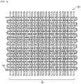
- Examples of the woven fabric include a woven fabric obtained by weaving either the carbon linear body or the resin linear body as a warp yarn and the other as a weft yarn (see FIG. 1).
- FIG. 1 illustrates one example of a woven fabric in which the carbon linear body and the resin linear body are woven as a warp yarn and a weft yarn, respectively (i.e., one example of the composite structure).
- "10" represents the carbon linear body
- "12” represents the resin linear body
- “101" represents the woven fabric.
- the woven fabric is not particularly restricted as long as it has a woven structure in which the carbon linear body and the resin linear body are regularly arranged.
- the woven fabric may be, for example, one obtained by alternately weaving one or more of each of the carbon linear body and the resin linear body as warp and weft yarns, or one obtained by weaving either the carbon linear body or the resin linear body into a woven structure of the other.
- the woven fabric may also be a woven fabric formed from a linear body obtained by twisting or doubling the carbon linear body and the resin linear body.
- the woven fabric according to the present embodiment can also be obtained by weaving only the linear body obtained by twisting or doubling the carbon linear body and the resin linear body, or the woven fabric may be a woven fabric formed from the linear body obtained by twisting or doubling the carbon linear body and the resin linear body, and at least one of the carbon linear body or the resin linear body that are not twisted or doubled with each other.
- the knitted fabric may be any knitted fabric obtained by weft knitting, warp knitting, lace knitting, a well-known applied knitting, or the like.
- the knitted fabric may also be a laminated body of plural knitted fabric layers.
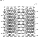
- Examples of the knitted fabric include a knitted fabric obtained by alternately knitting one or more Hof each of the carbon linear body and the resin linear body, for example, in a course direction (see FIG. 2 ). It is noted here, however, that FIG. 2 illustrates one example of a knitted fabric in which a single carbon linear body and a single resin linear body are alternately knitted in a course direction (i.e., another example of the composite structure). In FIG. 2 , “10" represents the carbon linear body, " 12" represents the resin linear body, and "102" represents the knitted fabric.
- the knitted fabric is not particularly restricted as long as it has a knitted structure in which the carbon linear body and the resin linear body are regularly arranged.
- the knitted fabric may be one in which the carbon linear body and the resin linear body are regularly arranged utilizing, for example, parallel knitting, plating knitting, or inlay knitting.
- the knitted fabric may also be a knitted fabric formed from a linear body obtained by twisting or doubling the carbon linear body and the resin linear body.
- the knitted fabric according to the present embodiment can also be obtained by knitting only the linear body obtained by twisting or doubling the carbon linear body and the resin linear body, or the knitted fabric may be a knitted fabric formed from the linear body obtained by twisting or doubling the carbon linear body and the resin linear body, and at least one of the carbon linear body or the resin linear body that are not twisted or doubled with each other.
- the wound body is a structure obtained by winding the carbon linear body and the resin linear body on a winding substrate (e.g., a cylindrical body, a polygonal columnar body, a cylindrical tubular body, a polygonal tubular body, or a plate body) and subsequently removing the winding substrate.
- a winding substrate e.g., a cylindrical body, a polygonal columnar body, a cylindrical tubular body, a polygonal tubular body, or a plate body
- the resulting wound body may be pressed into a sheet form.
- the resulting wound body may be cut-opened into a sheet form by cutting the wound body from one opening to the other opening. The cutting may be performed before or after the removal of the winding substrate.
- the wound body may be a laminated body of plural sheet-form wound bodies as well.
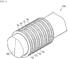
- Examples of the wound body include a wound body obtained by alternately arranging and spirally winding one or more of each of the carbon linear body and the resin linear body on a winding substrate (see FIG. 3).
- FIG. 3 illustrates one example of a wound body in which a single carbon linear body and a single resin linear body are alternately arranged and spirally wound on a winding substrate (i.e., yet another example of the composite structure).
- "10" represents the carbon linear body
- "12” represents the resin linear body
- "20” represents the winding substrate
- "103" represents the wound body.
- the wound body is not particularly restricted as long as it has a structure in which the carbon linear body and the resin linear body are regularly arranged.
- the wound body may be, for example, a wound body which has a layer formed by winding either the carbon linear body or the resin linear body on a winding substrate, and a layer formed by winding the other linear body thereon, or a wound body in which these two layers are alternately disposed on either other.
- the wound body may also be a wound body of at least one of a woven fabric, which is composed of a linear body obtained by twisting or doubling the carbon linear body and the resin linear body, the carbon linear body and the resin linear body, and a knitted fabric formed from the carbon linear body and the resin linear body.
- a woven fabric which is composed of a linear body obtained by twisting or doubling the carbon linear body and the resin linear body, the carbon linear body and the resin linear body, and a knitted fabric formed from the carbon linear body and the resin linear body.
- the wound body may be a wound body obtained by winding, on a winding substrate, at least one of a belt-form woven fabric a belt-form knitted fabric that is/are prepared in advance, and subsequently pulling out the winding substrate.
- the diameter of the resin linear body may be larger or smaller than the diameter of the carbon linear body.
- the below-described volume ratio of the carbon linear body and the resin linear body can be easily adjusted.
- the volume ratio of the carbon linear body and the resin linear body is preferably from 10/90 to 80/20, more preferably from 30/70 to 70/30.
- the volume of the carbon linear body and that of the resin linear body are selected in accordance with the volume ratio of the carbon linear body and the resin in the desired carbon-resin composite material.
- the carbon linear body is a carbon linear body containing a carbon material.
- Examples of the carbon material include carbon fibers and carbon nanotubes.
- the carbon linear body is preferably a linear body that contains carbon nanotubes (yarns utilizing carbon nanotubes) (such a linear body is hereinafter also referred to as "carbon nanotube linear body").
- carbon nanotube linear body a carbon-resin composite material having higher mechanical strength can be obtained as compared to when a linear body containing carbon fibers is used.
- a carbon nanotube linear body is advantageous in that it has higher flexibility than a linear body containing carbon fibers and, therefore, can yield a woven fabric, a knitted fabric or the like without being broken.
- a linear body containing carbon fibers may be used in combination with a carbon nanotube linear body.
- the use of a combination of a carbon nanotube linear body and a linear body containing carbon fibers is advantageous in that, since it yields a long and thin yarn, not only high tensile strength attributed to the carbon fibers but also an effect attributed to the carbon nanotube linear body, which is an effect of further improving the mechanical strength in the thickness direction, can both be attained.
- a carbon nanotube linear body can be obtained by, for example drawing carbon nanotubes into a sheet form from an edge of a carbon nanotube forest (i.e., a growth body sometimes referred to as "array", which is produced by growing plural carbon nanotubes on a substrate such that the carbon nanotubes are vertically oriented with respect to the substrate), bundling the thus drawn carbon nanotube sheet, and then twisting the resulting carbon nanotube bundle.
- a ribbon-form carbon nanotube linear body is obtained when no torsion is added during the twisting, while a thread-form linear body is obtained when torsion is added during the twisting.
- the ribbon-form carbon nanotube linear body is a linear body that does not have a structure in which carbon nanotubes are distorted.
- a carbon nanotube linear body can also be obtained by, for example, spinning from a dispersion of carbon nanotubes.
- the production of a carbon nanotube linear body by spinning can be performed in accordance with, for example, the method disclosed in US Patent Publication No. 2013/0251619 ( JP-ANo. 2011-253140 ).
- From the standpoint of obtaining a carbon nanotube linear body having a uniform diameter it is desirable to use a thread-form carbon nanotube linear body and, from the standpoint of obtaining a high-purity carbon nanotube linear body, it is preferred to obtain a thread-form carbon nanotube linear body by twisting a carbon nanotube sheet.
- the carbon nanotube linear body may also be a linear body in which two or more carbon nanotube linear-bodies are twisted together.
- the carbon nanotube linear body is desirably a linear body in which carbon nanotubes are oriented along the axial direction of the linear body.
- a carbon nanotube linear body in which carbon nanotubes are oriented along the axial direction of the linear body is used, the mechanical strength of the linear body is increased, as a result of which a carbon-resin composite material having high mechanical strength is likely to be obtained.
- a carbon nanotube linear body in which carbon nanotubes are oriented along the axial direction of the linear body can be obtained by drawing carbon nanotubes into a sheet form from an edge of a carbon nanotube forest, bundling the thus drawn carbon nanotube sheet, and then twisting, or twisting and distorting the resulting carbon nanotube bundle.
- the ratio of the carbon nanotubes with respect to the linear body is preferably 70% by mass or higher (more preferably 90% by mass or higher).
- the ratio of the carbon nanotubes is 70% by mass or higher, the mechanical strength of the carbon nanotube linear body is increased, as a result of which a carbon-resin composite material having high mechanical strength is likely to be obtained.
- the carbon linear body may also contain an additive that enhances the joining of the carbon linear body with the resin after the melting and solidification, or after the melting and curing of the resin linear body (e.g., UMEX (registered trademark) Series manufactured by Sanyo Chemical Industries, Inc. (maleic anhydride-modified polypropylene) or the like when the resin linear body contains a polyolefin-based resin).
- an additive that enhances the joining of the carbon linear body with the resin after the melting and solidification, or after the melting and curing of the resin linear body
- UMEX registered trademark
- Sanyo Chemical Industries, Inc. maleic anhydride-modified polypropylene
- the resin linear body is a resin linear body that contains at least one of a thermoplastic resin or a thermosetting resin.
- the resin linear body may contain either a thermoplastic resin or a thermosetting resin, or may contain both a thermoplastic resin and a thermosetting resin.
- the resin linear body contains a thermosetting resin, it is desired that the linear body further contains a heat-curing agent.
- thermoplastic resin examples include well-known resins, such as polyolefin resins, polyester resins, polyacrylic resins, polystyrene resins, polyimide resins, polyimide amide resins, polyamide resins, polyurethane resins, polycarbonate resins, polyarylate resins, phenoxy resins, urethane resins, silicone resins, and fluorocarbon resins; and layers containing a mixed resin of two or more of the above-described well-known resins.
- resins such as polyolefin resins, polyester resins, polyacrylic resins, polystyrene resins, polyimide resins, polyimide amide resins, polyamide resins, polyurethane resins, polycarbonate resins, polyarylate resins, phenoxy resins, urethane resins, silicone resins, and fluorocarbon resins.
- thermosetting resins examples include layers of well-known compositions, such as epoxy resin compositions, resin compositions cured by urethane reaction, and resin compositions cured by radical polymerization reaction.
- Examples of the epoxy resin compositions include combinations of an epoxy resin, such as a polyfunctional epoxy resin, a bisphenol A-type epoxy resin, a bisphenol F-type epoxy resin, a biphenyl-type epoxy resin or a dicyclopentadiene-type epoxy resin, and a curing agent such as an amine compound or a phenolic curing agent.
- an epoxy resin such as a polyfunctional epoxy resin, a bisphenol A-type epoxy resin, a bisphenol F-type epoxy resin, a biphenyl-type epoxy resin or a dicyclopentadiene-type epoxy resin
- a curing agent such as an amine compound or a phenolic curing agent.
- Examples of the resin compositions cured by urethane reaction include resin compositions containing a (meth)acrylic polyol and a polyisocyanate compound.
- Examples of the resin compositions cured by radical polymerization reaction include radical-polymerizable resin compositions containing a (meth)acryloyl group, an unsaturated polyester and the like, such as (meth)acrylic resins having a radical polymerizable group on a side chain (e.g., (meth)acrylic resins obtained by allowing a polymer of a reactive group-containing vinyl monomer (e.g., hydroxy (meth)acrylate or glycidyl (meth)acrylate) to react with a monomer that has a group reactive with the reactive group of the copolymer along with a radical-polymerizable group (e.g., (meth)acrylic acid or isocyanate group-containing (meth)acrylate)), (meth)acryl group-containing epoxy acrylates obtained by allowing (meth)acrylic acid or the like to react with a terminal of an epoxy resin, and unsaturated polyesters obtained by condensation of an unsaturated group-containing carboxylic acid
- the resin linear body is preferably a resin linear body that contains at least a thermoplastic resin.
- a carbon-resin composition material e.g., a three-dimensional carbon-resin composite material
- a resin linear body containing a thermoplastic resin is advantageous in that the separately prepared plural composite structures are easily joined together and that they are joined more strongly than in a prepreg containing carbon fiber layers.
- a resin linear body containing a thermoplastic resin is also advantageous in that it can also improve the productivity and the recyclability of the resulting carbon-resin composite material.
- thermosetting resins that can be imparted with fluidity prior to being cured
- it is harder to fill a thermoplastic resin into gaps; however, by adopting the above-described constitution for the composite structure, since the gaps between carbon linear-bodies are sufficiently filled with the thermoplastic resin when the composite structure is heated, a carbon-resin composite material having high strength can be obtained even with the use of a resin linear body containing a thermoplastic resin.
- the resin linear body may also contain an additive that enhances the joining of its resin with the carbon linear body at least one of after the melting and solidification or after the melting and curing of the resin linear body (e.g., UMEX (registered trademark) Series manufactured by Sanyo Chemical Industries, Inc. or the like when the resin linear body contains a polyolefin-based resin).
- an additive that enhances the joining of its resin with the carbon linear body at least one of after the melting and solidification or after the melting and curing of the resin linear body (e.g., UMEX (registered trademark) Series manufactured by Sanyo Chemical Industries, Inc. or the like when the resin linear body contains a polyolefin-based resin).
- the composite structure is heated. Specifically, when the resin linear body contains a thermoplastic resin, in the second step, the composite structure is heated to melt the resin linear body, after which the thus molten resin linear body is solidified. Meanwhile, when the resin linear body contains a thermosetting resin, in the second step, the composite structure is heated to melt the resin linear body, after which the thus molten resin linear body is cured.
- the resin linear body contains both a thermoplastic resin and a thermosetting resin
- the resins are melted by heating, then solidified, and cured. It is noted here, however, that there are cases where curing of the molten resin linear body proceeds but a solidification phenomenon does not take place.
- the heating temperature and the heating time are set as appropriate in accordance with the resin species.
- the composite structure may be heated while being molded (e.g., press molding).
- JP-A Japanese Patent Application Laid-Open
- 2018-104846 cited in the present description are incorporated herein by reference in their entirety.
Landscapes
- Engineering & Computer Science (AREA)
- Mechanical Engineering (AREA)
- Textile Engineering (AREA)
- Chemical & Material Sciences (AREA)
- Composite Materials (AREA)
- Reinforced Plastic Materials (AREA)
- Laminated Bodies (AREA)
- Woven Fabrics (AREA)
- Yarns And Mechanical Finishing Of Yarns Or Ropes (AREA)
Abstract
Description
- The present disclosure relates to: a method of producing a carbon-resin composite material; and a composite structure for producing a carbon-resin composite material.
- Conventionally, carbon-resin composite materials (CFRP) composed of carbon fibers and a thermosetting resin (a resin obtained by curing a thermosetting resin such as an epoxy resin or a phenol resin) and carbon-resin composite materials (CFRTP) composed of carbon fibers and a thermoplastic resin (e.g., a polypropylene resin or a polyamide resin) are known (see, for example, Patent Documents 1 and 2).
- These carbon-resin composite materials not only are lightweight but also have excellent mechanical properties (e.g., strength and rigidity), heat resistance and corrosion resistance. Accordingly, such carbon-resin composite materials have been utilized in a variety of fields (e.g., aviation, space industry, automobiles, railway vehicles, ships, civil engineering and construction, and sporting goods).
-
- [Patent Document 1] Japanese Patent Application Laid-Open (
JP-A) No. 2017-132932 - [Patent Document 2] Japanese National-Phase Publication (
JP-A) No. 2017-082215 - [Patent Document 3] Japanese National-Phase Publication (
JP-A) No. 2007-518890 - Incidentally, in carbon-resin composite materials, since a single carbon fiber does not have sufficient strength, bundled fibers each obtained by binding about 1,000 to 10,000 carbon fibers with a binder are used. For example, when a prepreg is produced from a carbon fiber layer and a resin film using such bundled fibers as in Patent Document 2, the adhesion between the carbon fiber layer and the resin film at their interface cannot be improved, and the resulting prepreg thus tends to have a low strength against mechanical load in the thickness direction.
- Meanwhile, technologies of opening the above-described bundled fibers have also been proposed (e.g., Patent Document 3). However, since the bundled fibers cannot be opened to a level of individual carbon fibers, it is difficult to impregnate a resin between the carbon fibers. Thus, gaps not impregnated with a resin are generated between the carbon fibers, and this tends to result in a variation in mechanical strength.
- In view of the above, an object of the present disclosure is to provide: a method of producing a carbon-resin composite material in which variation in mechanical strength can be reduced and the mechanical strength against mechanical load in the thickness direction can be improved; and a composite structure for producing a carbon-resin composite material used for the method.
- The above-described problems are solved by the following means.
-
- <1> A method of producing a carbon-resin composite material, the method including:
- a step of preparing a composite structure in which a carbon linear body containing a carbon material, and a resin linear body containing at least one of a thermoplastic resin or a thermosetting resin are regularly arranged; and
- a step of heating the composite structure.
- <2> The method of producing a carbon-resin composite material according to <1>, wherein the step of preparing a composite structure comprises preparing a composite structure that includes a linear body obtained by twisting or doubling the carbon linear body and the resin linear body.
- <3> The method of producing a carbon-resin composite material according to <1> or <2>, wherein the step of preparing a composite structure comprises preparing a composite structure that includes a woven fabric formed from the carbon linear body and the resin linear body.
- <4> The method of producing a carbon-resin composite material according to <1> or <2>, wherein the step of preparing a composite structure comprises preparing a composite structure that includes a knitted fabric formed from the carbon linear body and the resin linear body.
- <5> The method of producing a carbon-resin composite material according to any one of <1> to <4>, wherein the step of preparing a composite structure comprises preparing a composite structure that includes a wound body formed from the carbon linear body and the resin linear body.
- <6> The method of producing a carbon-resin composite material according to any one of <1> to <5>, wherein the resin linear body includes at least a thermoplastic resin.
- <7> The method of producing a carbon-resin composite material according to any one of <1> to <6>, wherein the carbon linear body is a linear body containing carbon nanotubes.
- <8> The method of producing a carbon-resin composite material according to <7>, wherein the linear body containing carbon nanotubes is a linear body in which the carbon nanotubes are oriented along an axial direction of the linear body.
- <9> The method of producing a carbon-resin composite material according to <7> or <8>, wherein, in the linear body containing carbon nanotubes, a ratio of the carbon nanotubes with respect to the linear body is 70% by mass or higher.
- <10> A composite structure for producing a carbon-resin composite material, in which a carbon linear body containing a carbon material, and a resin linear body containing a thermoplastic resin or a thermosetting resin are regularly arranged.
- According to the disclosure, a method of producing a carbon-resin composite material in which variation in mechanical strength can be reduced and the mechanical strength against mechanical load in the thickness direction can be improved, and a composite structure for producing a carbon-resin composite material used for the method can be provided.
-
-
FIG. 1 is a schematic plan view that illustrates, in the carbon-resin composite material according to the present embodiment, one example of the woven fabric formed from the carbon linear body and the resin linear body (one example of the composite structure in which the carbon linear body and the resin linear body are regularly arranged); -
FIG. 2 is a schematic plan view that illustrates, in the carbon-resin composite material according to the present embodiment, one example of the knitted fabric formed from the carbon linear body and the resin linear body (another example of the composite structure in which the carbon linear body and the resin linear body are regularly arranged); and -
FIG. 3 is a schematic plan view that illustrates, in the carbon-resin composite material according to the present embodiment, one example of the wound body composed of the carbon linear body and the resin linear body (yet another example of the composite structure in which the carbon linear body and the resin linear body are regularly arranged). - One exemplary embodiment of the disclosure is described below in detail.
- In the present specification, the same symbols are assigned to members having substantially the same functions in all of the drawings, and redundant descriptions thereof may be omitted.
- Those numerical ranges that are expressed with "to" each denote a range that includes the numerical values stated before and after "to" as the minimum value and the maximum value, respectively.
- In the stepwise range of numerical values shown in this specification, an upper limit value or a lower limit value disclosed in a certain range of numerical values may be replaced with an upper limit value or a lower limit value of another stepwise range of numerical values. In addition, in the range of numerical values disclosed in this specification, an upper limit value or a lower limit value disclosed in a certain range of numerical values may be replaced with values shown in examples.
- In this specification, a term "step" not only includes an independent step, but also includes a step, in a case where the step may not be distinguished from the other step, as long as the expected object of the step is achieved.
- The method of producing a carbon-resin composite material according to the present embodiment includes:
- the step of preparing a composite structure in which a carbon linear body containing a carbon material, and a resin linear body containing at least one of a thermoplastic resin or a thermosetting resin are regularly arranged (hereinafter, this step is also referred to as "first step"); and
- the step of heating the composite structure (hereinafter, this step is also referred to as "second step").
- In the method of producing a carbon-resin composite material according to the present embodiment, a composite structure in which a carbon linear body and a resin linear body are regularly arranged is used. In other words, this composite structure is in a state where the resin linear body is regularly arranged with respect to the carbon linear body. When the composite structure is heated, the resin linear body is melted and gaps between carbon linear-bodies are readily filled with the resin linear body, so that gaps between carbon linear-bodies that are not filled with a resin are unlikely to be generated. Consequently, in the resulting carbon-resin composite material, the carbon linear body and the resin can be closely joined together.
- In addition, the carbon linear body to be used is a continuous linear structure having no gap or only small gaps between carbon materials (e.g., carbon nanotubes or carbon fibers).
- Therefore, in the method of producing a carbon-resin composite material according to the present embodiment, a carbon-resin composite material in which variation in mechanical strength can be reduced and the strength against mechanical load in the thickness direction can be improved is obtained.
- The method of producing a carbon-resin composite material according to the present embodiment is described below in detail.
- In the first step, a composite structure in which a carbon linear body and a resin linear body are regularly arranged is prepared.
- Examples of the composite structure include a composite structure in which one or more of each of the carbon linear body and the resin linear body are parallelly and alternately arranged, and a composite structure in which parallelly arranged carbon linear-bodies and parallelly arranged resin linear-bodies are arranged in an intersecting manner.
- The composite structure may also be a structure in which separately prepared plural composite structures are disposed in layers.
- The composite structure is desirably one which includes a linear body obtained by twisting or doubling the carbon linear body and the resin linear body. By twisting or doubling the carbon linear body and the resin linear body in advance, a carbon-resin composite material having higher mechanical strength, in which the carbon linear body and a resin are closely joined together, can be obtained.
- The carbon linear body may be a carbon linear body obtained by twisting or doubling individual carbon linear-bodies, and the resin linear body may be a resin linear body obtained by twisting or doubling individual resin linear-bodies. The composite structure may also be one which includes: a linear body obtained by twisting or doubling the carbon linear body with the resin linear body; and at least one of a carbon linear body or a resin linear body in which these linear-bodies are not twisted or doubled with each other.
- Examples of the composite structure also include: a composite structure having a woven fabric formed from the carbon linear body and the resin linear body; a composite structure having a knitted fabric formed from the carbon linear body and the resin linear body; and a composite structure having a wound body composed of the carbon linear body and the resin linear body. Moreover, the composite structure may also be, for example, a composite structure having at least two of such woven fabric, knitted fabric or wound body.
- In a composite structure having at least one of such woven fabric, knitted fabric or wound body, the carbon linear body and the resin linear body are easily and regularly arranged at desired arrangement positions. Therefore, the mechanical strength of the resulting carbon-resin composite material in an arbitrary direction can be improved based on the arrangement positions.
- Further, this composite structure has high shape stability in that the arrangement positions of the carbon linear body and the resin linear body are unlikely to collapse prior to the second step (the step of heating the composite structure).
- The woven fabric may be any woven fabric obtained by plain weaving, twill weaving, satin weaving, a well-known applied weaving, or the like. The woven fabric may also be a laminated body of plural woven fabric layers.
- Examples of the woven fabric include a woven fabric obtained by weaving either the carbon linear body or the resin linear body as a warp yarn and the other as a weft yarn (see
FIG. 1). FIG. 1 illustrates one example of a woven fabric in which the carbon linear body and the resin linear body are woven as a warp yarn and a weft yarn, respectively (i.e., one example of the composite structure). InFIG. 1 , "10" represents the carbon linear body, "12" represents the resin linear body, and "101" represents the woven fabric. - The woven fabric is not particularly restricted as long as it has a woven structure in which the carbon linear body and the resin linear body are regularly arranged.
- The woven fabric may be, for example, one obtained by alternately weaving one or more of each of the carbon linear body and the resin linear body as warp and weft yarns, or one obtained by weaving either the carbon linear body or the resin linear body into a woven structure of the other.
- The woven fabric may also be a woven fabric formed from a linear body obtained by twisting or doubling the carbon linear body and the resin linear body. In this case, the woven fabric according to the present embodiment can also be obtained by weaving only the linear body obtained by twisting or doubling the carbon linear body and the resin linear body, or the woven fabric may be a woven fabric formed from the linear body obtained by twisting or doubling the carbon linear body and the resin linear body, and at least one of the carbon linear body or the resin linear body that are not twisted or doubled with each other.
- The knitted fabric may be any knitted fabric obtained by weft knitting, warp knitting, lace knitting, a well-known applied knitting, or the like. The knitted fabric may also be a laminated body of plural knitted fabric layers.
- Examples of the knitted fabric include a knitted fabric obtained by alternately knitting one or more Hof each of the carbon linear body and the resin linear body, for example, in a course direction (see
FIG. 2 ). It is noted here, however, thatFIG. 2 illustrates one example of a knitted fabric in which a single carbon linear body and a single resin linear body are alternately knitted in a course direction (i.e., another example of the composite structure). InFIG. 2 , "10" represents the carbon linear body, " 12" represents the resin linear body, and "102" represents the knitted fabric. - The knitted fabric is not particularly restricted as long as it has a knitted structure in which the carbon linear body and the resin linear body are regularly arranged.
- The knitted fabric may be one in which the carbon linear body and the resin linear body are regularly arranged utilizing, for example, parallel knitting, plating knitting, or inlay knitting.
- The knitted fabric may also be a knitted fabric formed from a linear body obtained by twisting or doubling the carbon linear body and the resin linear body. In this case, the knitted fabric according to the present embodiment can also be obtained by knitting only the linear body obtained by twisting or doubling the carbon linear body and the resin linear body, or the knitted fabric may be a knitted fabric formed from the linear body obtained by twisting or doubling the carbon linear body and the resin linear body, and at least one of the carbon linear body or the resin linear body that are not twisted or doubled with each other.
- The wound body is a structure obtained by winding the carbon linear body and the resin linear body on a winding substrate (e.g., a cylindrical body, a polygonal columnar body, a cylindrical tubular body, a polygonal tubular body, or a plate body) and subsequently removing the winding substrate. After the removal of the winding substrate, the resulting wound body may be pressed into a sheet form. Alternatively, the resulting wound body may be cut-opened into a sheet form by cutting the wound body from one opening to the other opening. The cutting may be performed before or after the removal of the winding substrate. Further, the wound body may be a laminated body of plural sheet-form wound bodies as well.
- Examples of the wound body include a wound body obtained by alternately arranging and spirally winding one or more of each of the carbon linear body and the resin linear body on a winding substrate (see
FIG. 3). FIG. 3 illustrates one example of a wound body in which a single carbon linear body and a single resin linear body are alternately arranged and spirally wound on a winding substrate (i.e., yet another example of the composite structure). InFIG. 3 , "10" represents the carbon linear body, "12" represents the resin linear body, "20" represents the winding substrate, and "103" represents the wound body. - The wound body is not particularly restricted as long as it has a structure in which the carbon linear body and the resin linear body are regularly arranged.
- The wound body may be, for example, a wound body which has a layer formed by winding either the carbon linear body or the resin linear body on a winding substrate, and a layer formed by winding the other linear body thereon, or a wound body in which these two layers are alternately disposed on either other.
- The wound body may also be a wound body of at least one of a woven fabric, which is composed of a linear body obtained by twisting or doubling the carbon linear body and the resin linear body, the carbon linear body and the resin linear body, and a knitted fabric formed from the carbon linear body and the resin linear body.
- Specifically, for example, the wound body may be a wound body obtained by winding, on a winding substrate, at least one of a belt-form woven fabric a belt-form knitted fabric that is/are prepared in advance, and subsequently pulling out the winding substrate.
- In the composite structure, the diameter of the resin linear body may be larger or smaller than the diameter of the carbon linear body.
- By adjusting the diameter of the carbon linear body and that of the resin linear body, the below-described volume ratio of the carbon linear body and the resin linear body can be easily adjusted.
- In the composite structure, the volume ratio of the carbon linear body and the resin linear body (carbon linear body/resin linear body) is preferably from 10/90 to 80/20, more preferably from 30/70 to 70/30.
- The volume of the carbon linear body and that of the resin linear body are selected in accordance with the volume ratio of the carbon linear body and the resin in the desired carbon-resin composite material.
- The carbon linear body is a carbon linear body containing a carbon material. Examples of the carbon material include carbon fibers and carbon nanotubes.
- The carbon linear body is preferably a linear body that contains carbon nanotubes (yarns utilizing carbon nanotubes) (such a linear body is hereinafter also referred to as "carbon nanotube linear body"). When a carbon nanotube linear body is used as the carbon linear body, a carbon-resin composite material having higher mechanical strength can be obtained as compared to when a linear body containing carbon fibers is used. In addition, a carbon nanotube linear body is advantageous in that it has higher flexibility than a linear body containing carbon fibers and, therefore, can yield a woven fabric, a knitted fabric or the like without being broken.
- As the carbon linear body, a linear body containing carbon fibers may be used in combination with a carbon nanotube linear body. The use of a combination of a carbon nanotube linear body and a linear body containing carbon fibers is advantageous in that, since it yields a long and thin yarn, not only high tensile strength attributed to the carbon fibers but also an effect attributed to the carbon nanotube linear body, which is an effect of further improving the mechanical strength in the thickness direction, can both be attained.
- A carbon nanotube linear body can be obtained by, for example drawing carbon nanotubes into a sheet form from an edge of a carbon nanotube forest (i.e., a growth body sometimes referred to as "array", which is produced by growing plural carbon nanotubes on a substrate such that the carbon nanotubes are vertically oriented with respect to the substrate), bundling the thus drawn carbon nanotube sheet, and then twisting the resulting carbon nanotube bundle. In this production method, a ribbon-form carbon nanotube linear body is obtained when no torsion is added during the twisting, while a thread-form linear body is obtained when torsion is added during the twisting. The ribbon-form carbon nanotube linear body is a linear body that does not have a structure in which carbon nanotubes are distorted. In addition, a carbon nanotube linear body can also be obtained by, for example, spinning from a dispersion of carbon nanotubes. The production of a carbon nanotube linear body by spinning can be performed in accordance with, for example, the method disclosed in
US Patent Publication No. 2013/0251619 (JP-ANo. 2011-253140 - The carbon nanotube linear body is desirably a linear body in which carbon nanotubes are oriented along the axial direction of the linear body. When a carbon nanotube linear body in which carbon nanotubes are oriented along the axial direction of the linear body is used, the mechanical strength of the linear body is increased, as a result of which a carbon-resin composite material having high mechanical strength is likely to be obtained.
- A carbon nanotube linear body in which carbon nanotubes are oriented along the axial direction of the linear body can be obtained by drawing carbon nanotubes into a sheet form from an edge of a carbon nanotube forest, bundling the thus drawn carbon nanotube sheet, and then twisting, or twisting and distorting the resulting carbon nanotube bundle.
- In the carbon nanotube linear body, the ratio of the carbon nanotubes with respect to the linear body is preferably 70% by mass or higher (more preferably 90% by mass or higher). When the ratio of the carbon nanotubes is 70% by mass or higher, the mechanical strength of the carbon nanotube linear body is increased, as a result of which a carbon-resin composite material having high mechanical strength is likely to be obtained.
- The carbon linear body may also contain an additive that enhances the joining of the carbon linear body with the resin after the melting and solidification, or after the melting and curing of the resin linear body (e.g., UMEX (registered trademark) Series manufactured by Sanyo Chemical Industries, Inc. (maleic anhydride-modified polypropylene) or the like when the resin linear body contains a polyolefin-based resin).
- The resin linear body is a resin linear body that contains at least one of a thermoplastic resin or a thermosetting resin. In other words, the resin linear body may contain either a thermoplastic resin or a thermosetting resin, or may contain both a thermoplastic resin and a thermosetting resin. When the resin linear body contains a thermosetting resin, it is desired that the linear body further contains a heat-curing agent.
- Examples of the thermoplastic resin include well-known resins, such as polyolefin resins, polyester resins, polyacrylic resins, polystyrene resins, polyimide resins, polyimide amide resins, polyamide resins, polyurethane resins, polycarbonate resins, polyarylate resins, phenoxy resins, urethane resins, silicone resins, and fluorocarbon resins; and layers containing a mixed resin of two or more of the above-described well-known resins.
- Examples of the thermosetting resins include layers of well-known compositions, such as epoxy resin compositions, resin compositions cured by urethane reaction, and resin compositions cured by radical polymerization reaction.
- Examples of the epoxy resin compositions include combinations of an epoxy resin, such as a polyfunctional epoxy resin, a bisphenol A-type epoxy resin, a bisphenol F-type epoxy resin, a biphenyl-type epoxy resin or a dicyclopentadiene-type epoxy resin, and a curing agent such as an amine compound or a phenolic curing agent.
- Examples of the resin compositions cured by urethane reaction include resin compositions containing a (meth)acrylic polyol and a polyisocyanate compound.
- Examples of the resin compositions cured by radical polymerization reaction include radical-polymerizable resin compositions containing a (meth)acryloyl group, an unsaturated polyester and the like, such as (meth)acrylic resins having a radical polymerizable group on a side chain (e.g., (meth)acrylic resins obtained by allowing a polymer of a reactive group-containing vinyl monomer (e.g., hydroxy (meth)acrylate or glycidyl (meth)acrylate) to react with a monomer that has a group reactive with the reactive group of the copolymer along with a radical-polymerizable group (e.g., (meth)acrylic acid or isocyanate group-containing (meth)acrylate)), (meth)acryl group-containing epoxy acrylates obtained by allowing (meth)acrylic acid or the like to react with a terminal of an epoxy resin, and unsaturated polyesters obtained by condensation of an unsaturated group-containing carboxylic acid (e.g., fumaric acid) with a diol.
- Thereamong, the resin linear body is preferably a resin linear body that contains at least a thermoplastic resin.
- For example, in cases where a carbon-resin composition material (e.g., a three-dimensional carbon-resin composite material) is produced by applying, as the composite structure, a structure in which separately prepared plural composite structures are disposed in layers, the use of a resin linear body containing a thermoplastic resin is advantageous in that the separately prepared plural composite structures are easily joined together and that they are joined more strongly than in a prepreg containing carbon fiber layers.
- Further, the use of a resin linear body containing a thermoplastic resin is also advantageous in that it can also improve the productivity and the recyclability of the resulting carbon-resin composite material.
- Usually, as compared to thermosetting resins that can be imparted with fluidity prior to being cured, it is harder to fill a thermoplastic resin into gaps; however, by adopting the above-described constitution for the composite structure, since the gaps between carbon linear-bodies are sufficiently filled with the thermoplastic resin when the composite structure is heated, a carbon-resin composite material having high strength can be obtained even with the use of a resin linear body containing a thermoplastic resin.
- The resin linear body may also contain an additive that enhances the joining of its resin with the carbon linear body at least one of after the melting and solidification or after the melting and curing of the resin linear body (e.g., UMEX (registered trademark) Series manufactured by Sanyo Chemical Industries, Inc. or the like when the resin linear body contains a polyolefin-based resin).
- In the second step, the composite structure is heated. Specifically, when the resin linear body contains a thermoplastic resin, in the second step, the composite structure is heated to melt the resin linear body, after which the thus molten resin linear body is solidified. Meanwhile, when the resin linear body contains a thermosetting resin, in the second step, the composite structure is heated to melt the resin linear body, after which the thus molten resin linear body is cured.
- When the resin linear body contains both a thermoplastic resin and a thermosetting resin, in the second step, the resins are melted by heating, then solidified, and cured. It is noted here, however, that there are cases where curing of the molten resin linear body proceeds but a solidification phenomenon does not take place.
- In the second step, the heating temperature and the heating time are set as appropriate in accordance with the resin species. In the second step, the composite structure may be heated while being molded (e.g., press molding).
- By performing the above-described steps, a carbon-resin composite material in which variation in mechanical strength is reduced and, particularly, the strength against a mechanical load in the thickness direction can be improved, is obtained.
- The description of symbols is provided as below.
- 101: woven fabric
- 102: knitted fabric
- 103: wound body
- 10: carbon linear body
- 12: resin linear body
- The disclosure of Japanese Patent Application Laid-Open (
JP-A) No. 2018-104846 - All publications, patent applications, and technical standards described herein are incorporated herein by reference in their entirety to the same extent as if the publications, patent applications, and technical standards have been written specifically and individually to be incorporated by reference.
Claims (10)
- A method of producing a carbon-resin composite material, the method comprising:a step of preparing a composite structure in which a carbon linear body containing a carbon material, and a resin linear body containing at least one of a thermoplastic resin or a thermosetting resin, are regularly arranged; anda step of heating the composite structure.
- The method of producing a carbon-resin composite material according to claim 1, wherein the step of preparing a composite structure comprises preparing a composite structure that includes a linear body obtained by twisting or doubling the carbon linear body and the resin linear body.
- The method of producing a carbon-resin composite material according to claim 1 or 2, wherein the step of preparing a composite structure comprises preparing a composite structure that includes a woven fabric formed from the carbon linear body and the resin linear body.
- The method of producing a carbon-resin composite material according to claim 1 or 2, wherein the step of preparing a composite structure comprises preparing a composite structure that includes a knitted fabric formed from the carbon linear body and the resin linear body.
- The method of producing a carbon-resin composite material according to any one of claims 1 to 4, wherein the step of preparing a composite structure comprises preparing a composite structure that includes a wound body formed from the carbon linear body and the resin linear body.
- The method of producing a carbon-resin composite material according to any one of claims 1 to 5, wherein the resin linear body includes at least a thermoplastic resin.
- The method of producing a carbon-resin composite material according to any one of claims 1 to 6, wherein the carbon linear body is a linear body containing carbon nanotubes.
- The method of producing a carbon-resin composite material according to claim 7, wherein, in the linear body containing carbon nanotubes, the carbon nanotubes are oriented along an axial direction of the linear body.
- The method of producing a carbon-resin composite material according to claim 7 or 8, wherein, in the linear body containing carbon nanotubes, a ratio of the carbon nanotubes with respect to the linear body is 70% by mass or higher.
- A composite structure for producing a carbon-resin composite material, in which a carbon linear body containing a carbon material, and a resin linear body containing a thermoplastic resin or a thermosetting resin, are regularly arranged.
Applications Claiming Priority (2)
| Application Number | Priority Date | Filing Date | Title |
|---|---|---|---|
| JP2018104846 | 2018-05-31 | ||
| PCT/JP2019/021124 WO2019230729A1 (en) | 2018-05-31 | 2019-05-28 | Method for producing carbon resin composite material and composite structure for production of carbon resin composite material |
Publications (2)
| Publication Number | Publication Date |
|---|---|
| EP3804935A1 true EP3804935A1 (en) | 2021-04-14 |
| EP3804935A4 EP3804935A4 (en) | 2022-02-23 |
Family
ID=68698217
Family Applications (1)
| Application Number | Title | Priority Date | Filing Date |
|---|---|---|---|
| EP19810109.9A Withdrawn EP3804935A4 (en) | 2018-05-31 | 2019-05-28 | METHOD FOR PRODUCTION OF CARBON RESIN COMPOSITE MATERIAL AND COMPOSITE STRUCTURE FOR PRODUCTION OF CARBON RESIN COMPOSITE MATERIAL |
Country Status (7)
| Country | Link |
|---|---|
| US (1) | US20210187788A1 (en) |
| EP (1) | EP3804935A4 (en) |
| JP (1) | JP7222989B2 (en) |
| KR (1) | KR102892409B1 (en) |
| CN (1) | CN112203819A (en) |
| TW (1) | TWI884918B (en) |
| WO (1) | WO2019230729A1 (en) |
Family Cites Families (81)
| Publication number | Priority date | Publication date | Assignee | Title |
|---|---|---|---|---|
| US2202013A (en) * | 1938-01-13 | 1940-05-28 | Lougheed Victor | Reinforced plastic and material therefor |
| US3551269A (en) * | 1967-03-06 | 1970-12-29 | Owens Corning Fiberglass Corp | Glass fiber-plastic composites of improved strength |
| US3983282A (en) * | 1972-05-15 | 1976-09-28 | Seemann Iii William H | Fabric constructions useful as building bases in forming compound-curved structures |
| US4100322A (en) * | 1974-12-11 | 1978-07-11 | Mcdonnell Douglas Corporation | Fiber-resin-carbon composites and method of fabrication |
| US4131708A (en) * | 1976-07-27 | 1978-12-26 | Fiber Materials, Inc. | Selectively modified carbon-carbon composites |
| JPS543643A (en) * | 1977-06-10 | 1979-01-11 | Tsugio Kobayashi | Gear comosed of carbon fiber |
| US4260143A (en) * | 1979-01-15 | 1981-04-07 | Celanese Corporation | Carbon fiber reinforced composite coil spring |
| FR2473567A1 (en) * | 1979-12-21 | 1981-07-17 | Brochier & Fils | COMPLEX WOVEN MATERIAL AND LAMINATE ARTICLES MADE THEREFROM |
| US4590122A (en) * | 1980-12-18 | 1986-05-20 | Fiberite Corporation | High conductivity graphite material with electrically conductive filaments wrapped around warp and fill elements |
| US4410385A (en) * | 1981-01-28 | 1983-10-18 | General Electric Company | Method of making a composite article |
| US4615934A (en) * | 1985-11-22 | 1986-10-07 | Peabody Abc Corporation | Warp knit weft insertion fabric and plastic sheet reinforced therewith |
| JPS62231073A (en) * | 1986-03-31 | 1987-10-09 | 石川県 | Production of carbon fiber composite material |
| JPS6445841A (en) * | 1987-08-13 | 1989-02-20 | Nitto Boseki Co Ltd | Fabric for fiber reinforced thermoplastic resin laminate material |
| JPH0192232A (en) * | 1987-10-02 | 1989-04-11 | Asahi Chem Ind Co Ltd | Complex structure of thermoplastic resin |
| CA1309283C (en) * | 1988-02-02 | 1992-10-27 | Ronald Frank Mcconnell | In-line consolidation of braided structures |
| JPH01280017A (en) * | 1988-04-28 | 1989-11-10 | Teijin Ltd | Multifilament yarn for formed product matrix resin |
| US5292578A (en) * | 1988-06-16 | 1994-03-08 | Koelzer Klaus K | Material for reinforcing duroplastics woven fabric for reinforcing duroplastics having a specific distribution of hollow thermoplastic microspheres within the thread system |
| FR2640908B1 (en) * | 1988-12-23 | 1991-06-14 | Brochier Sa | |
| US5244693A (en) * | 1989-03-15 | 1993-09-14 | Kanebo Ltd. | Process for the preparation of a network article |
| EP0461464A1 (en) | 1990-05-29 | 1991-12-18 | Bando Chemical Industries, Limited | Vibration-isolating material |
| US5888609A (en) * | 1990-12-18 | 1999-03-30 | Valtion Teknillinen Tutkimuskeskus | Planar porous composite structure and method for its manufacture |
| DE4139333A1 (en) | 1991-11-29 | 1993-06-03 | Abb Patent Gmbh | MACHINE COMPONENT MADE OF FIBER COMPOSITE |
| US5401564A (en) * | 1993-03-23 | 1995-03-28 | Hexcel Corporation | Materials and processes for fabricating formed composite articles and use in shoe arch |
| DE19513506A1 (en) * | 1995-04-10 | 1996-10-17 | Hoechst Ag | Hybrid yarn and permanently deformable textile material made from it, its production and use |
| TW434360B (en) * | 1998-02-18 | 2001-05-16 | Toray Industries | Carbon fiber matrix for reinforcement, laminate and detecting method |
| US6251809B1 (en) * | 1998-10-30 | 2001-06-26 | Terry S. Creasy | Composite materials with highly aligned discontinuous fibers, and methods of preparation thereof |
| US6299812B1 (en) * | 1999-08-16 | 2001-10-09 | The Board Of Regents Of The University Of Oklahoma | Method for forming a fibers/composite material having an anisotropic structure |
| JP5770962B2 (en) * | 1999-12-07 | 2015-08-26 | ウィリアム・マーシュ・ライス・ユニバーシティ | Oriented nanofibers embedded in a polymer matrix |
| EP1238128B1 (en) * | 1999-12-15 | 2005-11-30 | N.V. Bekaert S.A. | Reinforced fabric |
| CA2442512C (en) * | 2001-04-04 | 2011-01-04 | Habasit Ag | Belt comprising a woven fabric having an even-sided plural-wale twill weave |
| WO2003052185A1 (en) * | 2001-12-19 | 2003-06-26 | Toray Industries, Inc. | Carbon fiber-made reinforing woven fabric and prepreg and prepreg production method |
| US8361608B1 (en) * | 2002-04-17 | 2013-01-29 | Conductive Composites Company, L.L.C. | Electrically-conductive nanocomposite material |
| US8187703B2 (en) * | 2003-06-16 | 2012-05-29 | William Marsh Rice University | Fiber-reinforced polymer composites containing functionalized carbon nanotubes |
| CN101818397B (en) | 2003-07-08 | 2011-10-12 | 福井县 | Method of producing a spread multi-filament bundle and an apparatus used in the same |
| US7628041B2 (en) * | 2004-02-27 | 2009-12-08 | Alcatel-Lucent Usa Inc. | Carbon particle fiber assembly technique |
| ITTO20040208A1 (en) * | 2004-03-29 | 2004-06-29 | Alenia Aeronautica Spa | TAPES OF CONTINUOUS FILAMENTS AND TRESTLES FOR FORMING THE REINFORCEMENT LAYERS FOR AN ELEMENT COMPOSITE WITH A RESIN DIE. |
| GB0423948D0 (en) * | 2004-10-28 | 2004-12-01 | Qinetiq Ltd | Composite materials |
| KR100630578B1 (en) * | 2005-10-19 | 2006-10-04 | 전북대학교산학협력단 | Nanofiber-reinforced composite material and its manufacturing method |
| US9181639B2 (en) * | 2006-05-19 | 2015-11-10 | Massachusetts Institute Of Technology | Continuous process for the production of nanostructures including nanotubes |
| JP4969363B2 (en) * | 2006-08-07 | 2012-07-04 | 東レ株式会社 | Prepreg and carbon fiber reinforced composites |
| CN101269611A (en) * | 2007-03-23 | 2008-09-24 | 邱长埙 | Bicycle rim structure made of carbon fiber woven material and method thereof |
| US9012021B2 (en) * | 2008-03-26 | 2015-04-21 | Xerox Corporation | Composition of matter for composite plastic contact elements featuring controlled conduction pathways, and related manufacturing processes |
| US20110159270A9 (en) * | 2008-06-02 | 2011-06-30 | Texas A & M University System | Carbon nanotube fiber-reinforced polymer composites having improved fatigue durability and methods for production thereof |
| US20100021682A1 (en) * | 2008-07-25 | 2010-01-28 | Florida State University Research Foundation | Composite material and method for increasing z-axis thermal conductivity of composite sheet material |
| WO2010118381A1 (en) * | 2009-04-10 | 2010-10-14 | Lockheed Martin Corporation | Method and apparatus for using a vertical furnace to infuse carbon nanotubes to fiber |
| FR2945549B1 (en) * | 2009-05-12 | 2012-07-27 | Arkema France | FIBROUS SUBSTRATE, METHOD FOR MANUFACTURING AND USE OF SUCH A FIBROUS SUBSTRATE |
| JP2011213090A (en) * | 2009-09-29 | 2011-10-27 | Sekisui Chem Co Ltd | Resin laminated sheet |
| US8574677B2 (en) * | 2010-05-12 | 2013-11-05 | James L. Lee | Layer-by-layer fabrication method of sprayed nanopaper |
| US20110281044A1 (en) * | 2010-05-17 | 2011-11-17 | Spyros Michail | Composite structures with unidirectional fibers |
| JP2011253140A (en) | 2010-06-04 | 2011-12-15 | Konica Minolta Business Technologies Inc | Fixing device and image forming device |
| TWI438318B (en) * | 2010-08-27 | 2014-05-21 | 鴻海精密工業股份有限公司 | Nano carbon tube composite linear structure and preparation method thereof |
| JP2014508370A (en) * | 2010-09-23 | 2014-04-03 | アプライド ナノストラクチャード ソリューションズ リミテッド ライアビリティー カンパニー | CNT-infused fibers as self-shielding wires for reinforced transmission lines |
| US9233492B2 (en) * | 2010-10-12 | 2016-01-12 | Florida State University Research Foundation, Inc. | Composite materials reinforced with carbon nanotube yarns |
| EP2629962B1 (en) * | 2010-10-18 | 2019-06-12 | Short Brothers Plc | Method of forming a composite material with added nanoparticles |
| WO2012070537A1 (en) * | 2010-11-22 | 2012-05-31 | 古河電気工業株式会社 | Coagulation spinning structure and production method therefor, and electric wire using same |
| US20120282453A1 (en) * | 2011-05-05 | 2012-11-08 | North Carolina State University | Carbon nanotube composites and methods and apparatus for fabricating same |
| US20180002512A9 (en) * | 2011-07-21 | 2018-01-04 | Entegris, Inc. | Nanotube and finely milled carbon fiber polymer composite compositions and methods of making |
| JP2013135005A (en) * | 2011-12-26 | 2013-07-08 | Hitachi Zosen Corp | Fibrous carbon-containing resin |
| US20130216390A1 (en) * | 2012-02-20 | 2013-08-22 | Bayer Materialscience Llc | Reinforced composites produced by a vacuum infusion or pultrusion process |
| US8833434B2 (en) * | 2012-06-08 | 2014-09-16 | GM Global Technology Operations LLC | Pt nanotubes |
| HUE036249T2 (en) * | 2012-10-18 | 2018-06-28 | Toray Industries | Carbon Fiber Reinforced Resin Preparation, Carbon Fiber Reinforced Resin Preparation, Formulation, Process Formulation, and Formulated Carbon Fiber Reinforced Resin Product |
| JP2014169521A (en) | 2013-02-05 | 2014-09-18 | Honda Motor Co Ltd | Carbon nanotube fiber and manufacturing method thereof |
| JP2014173196A (en) * | 2013-03-06 | 2014-09-22 | Gifu Univ | Mixed yarn, woven fabric and knitted fabric, composite material and method for manufacturing composite material |
| WO2014197078A2 (en) * | 2013-03-14 | 2014-12-11 | The Board Of Regents, The University Of Texas System | Method of fabricating carbon nanotube sheet scrolled fiber reinforced polymer composites and compositions and uses thereof |
| WO2015120011A1 (en) * | 2014-02-04 | 2015-08-13 | N12 Technologies, Inc. | Articles and methods for manufacture of nanostructure reinforced composites |
| US10399322B2 (en) * | 2014-06-11 | 2019-09-03 | Applied Nanostructured Solutions, Llc | Three-dimensional printing using carbon nanostructures |
| US10213984B2 (en) * | 2014-09-22 | 2019-02-26 | Cytec Industries Inc. | Composite materials with high Z-direction electrical conductivity |
| JP6541147B2 (en) * | 2015-02-04 | 2019-07-10 | 本田技研工業株式会社 | Nanofiber-polymer composite and method for producing the same |
| WO2016136685A1 (en) * | 2015-02-23 | 2016-09-01 | リンテック オブ アメリカ インク | Adhesive sheet |
| KR101883889B1 (en) * | 2015-02-27 | 2018-08-01 | 히다치 조센 가부시키가이샤 | Method for manufacturing carbon nanotube fiber, device for manufacturing carbon nanotube fiber, and carbon nanotube fiber |
| SG10201502009XA (en) * | 2015-03-16 | 2016-01-28 | Ha Fee Ho | Pre-Impregnated Composite Material |
| US20160273161A1 (en) * | 2015-03-16 | 2016-09-22 | Ha Fee Christine HO | Pre-impregnated composite material |
| JP2017002411A (en) * | 2015-06-04 | 2017-01-05 | ナノサミット株式会社 | Method for producing carbon nanotube fiber and carbon nanotube fiber produced by the production method |
| JP6957859B2 (en) | 2015-10-29 | 2021-11-02 | 東レ株式会社 | Fiber-reinforced thermoplastic resin molded products and fiber-reinforced thermoplastic resin molded materials |
| KR20180097523A (en) * | 2015-12-25 | 2018-08-31 | 도레이 카부시키가이샤 | Prepreg and its manufacturing method |
| KR101762681B1 (en) | 2016-01-06 | 2017-07-28 | 곽성남 | Symbolic sculpture and construction method of the symbolic sculpture |
| JP6519492B2 (en) | 2016-01-29 | 2019-05-29 | 東レ株式会社 | Prepreg and fiber reinforced composite materials |
| KR101863549B1 (en) | 2016-05-24 | 2018-06-05 | 주식회사 세미콘라이트 | Semiconductor light emitting device |
| JP2018016030A (en) * | 2016-07-29 | 2018-02-01 | 学校法人幾徳学園 | Carbon fiber-reinforced plastic and method for producing the same |
| JP6607609B2 (en) | 2016-12-27 | 2019-11-20 | 金星製紙株式会社 | Extra fine fiber nonwoven fabric |
| CN111868146A (en) * | 2018-01-11 | 2020-10-30 | 纳诺科尔有限公司 | Composites containing mechanoligands |
-
2019
- 2019-05-28 KR KR1020207033642A patent/KR102892409B1/en active Active
- 2019-05-28 US US17/059,317 patent/US20210187788A1/en not_active Abandoned
- 2019-05-28 CN CN201980036279.XA patent/CN112203819A/en active Pending
- 2019-05-28 WO PCT/JP2019/021124 patent/WO2019230729A1/en not_active Ceased
- 2019-05-28 EP EP19810109.9A patent/EP3804935A4/en not_active Withdrawn
- 2019-05-28 JP JP2020522215A patent/JP7222989B2/en active Active
- 2019-05-30 TW TW108118653A patent/TWI884918B/en active
Also Published As
| Publication number | Publication date |
|---|---|
| EP3804935A4 (en) | 2022-02-23 |
| JPWO2019230729A1 (en) | 2021-08-19 |
| CN112203819A (en) | 2021-01-08 |
| WO2019230729A1 (en) | 2019-12-05 |
| JP7222989B2 (en) | 2023-02-15 |
| KR20210015798A (en) | 2021-02-10 |
| US20210187788A1 (en) | 2021-06-24 |
| TWI884918B (en) | 2025-06-01 |
| TW202003648A (en) | 2020-01-16 |
| KR102892409B1 (en) | 2025-11-28 |
Similar Documents
| Publication | Publication Date | Title |
|---|---|---|
| US20230241837A1 (en) | Continuous Fiber Reinforced Thermoplastic Resin Composite Material and Method for Producing Same | |
| JP6138045B2 (en) | Method for producing high-weight carbon fiber sheet for RTM method and RTM method | |
| EP3028852B1 (en) | Continuous fiber reinforced resin composite material and molded article thereof | |
| EP1731282A1 (en) | Preform, frp, and processes for producing these | |
| EP0033244A2 (en) | Fibre reinforced materials and methods of making and using them | |
| JPWO2017094633A1 (en) | In-situ polymerization type thermoplastic prepreg, thermoplastic composite and production method thereof | |
| US10384400B2 (en) | Thermoplastic resin composite and preparation method of thermoplastic resin composite | |
| KR20140005409A (en) | Thermoplastic prepreg and method for producing the same | |
| JP2019099987A (en) | Reinforced-fiber substrate, reinforced-fiber laminate and fiber-reinforced resin | |
| JP2018065999A (en) | Fiber-reinforced base material, fiber-reinforced laminate and fiber-reinforced resin | |
| WO2019066012A1 (en) | Reinforcing fiber bundle, reinforcing fiber open fabric, and fiber-reinforced composite, and manufacturing method thereof | |
| AU2019230317B2 (en) | Dry tape material for fiber placement use, method for producing same, and reinforcing fiber laminate and fiber-reinforced resin molded article each produced using same | |
| JPH0771804B2 (en) | Carbon fiber prepreg and carbon fiber reinforced resin | |
| US20210187788A1 (en) | Method of producing carbon-resin composite material, and composite structure for producing carbon-resin composite material | |
| US20250289210A1 (en) | Hybrid-type fiber-reinforced composite material and apparatus for producing same | |
| KR20160085384A (en) | Fiber reinforced composite material and method of manufacturing the same | |
| EP4140710A1 (en) | Reinforced fiber tape material and production method therefor, fiber reinforced resin | |
| EP3737653B1 (en) | Fiber reinforced materials with improved fatigue performance | |
| JP2012251043A (en) | Thread, sheet-like reinforcing fiber base material, preform and method for manufacturing fiber reinforced composite material | |
| JP2019111710A (en) | Carbon fiber tape material and laminate sheet base thereof | |
| JP2010031088A (en) | Partially impregnated tow prepreg and apparatus for producing the same | |
| KR102893257B1 (en) | Continuous fiber reinforced composite material | |
| EP4506494B1 (en) | Shapeable fabric | |
| CA3087532C (en) | Fiber reinforced materials with improved fatigue performance | |
| KR102063602B1 (en) | Fiber reinforced composite material sheet and method of manufacturing the same |
Legal Events
| Date | Code | Title | Description |
|---|---|---|---|
| STAA | Information on the status of an ep patent application or granted ep patent |
Free format text: STATUS: THE INTERNATIONAL PUBLICATION HAS BEEN MADE |
|
| PUAI | Public reference made under article 153(3) epc to a published international application that has entered the european phase |
Free format text: ORIGINAL CODE: 0009012 |
|
| STAA | Information on the status of an ep patent application or granted ep patent |
Free format text: STATUS: REQUEST FOR EXAMINATION WAS MADE |
|
| 17P | Request for examination filed |
Effective date: 20201218 |
|
| AK | Designated contracting states |
Kind code of ref document: A1 Designated state(s): AL AT BE BG CH CY CZ DE DK EE ES FI FR GB GR HR HU IE IS IT LI LT LU LV MC MK MT NL NO PL PT RO RS SE SI SK SM TR |
|
| AX | Request for extension of the european patent |
Extension state: BA ME |
|
| DAV | Request for validation of the european patent (deleted) | ||
| DAX | Request for extension of the european patent (deleted) | ||
| A4 | Supplementary search report drawn up and despatched |
Effective date: 20220126 |
|
| RIC1 | Information provided on ipc code assigned before grant |
Ipc: B29K 105/16 20060101ALI20220120BHEP Ipc: B29C 70/22 20060101ALI20220120BHEP Ipc: B29C 70/14 20060101ALI20220120BHEP Ipc: B29C 70/08 20060101ALI20220120BHEP Ipc: B29K 105/08 20060101ALI20220120BHEP Ipc: B29C 70/16 20060101ALI20220120BHEP Ipc: B29B 11/16 20060101AFI20220120BHEP |
|
| STAA | Information on the status of an ep patent application or granted ep patent |
Free format text: STATUS: EXAMINATION IS IN PROGRESS |
|
| 17Q | First examination report despatched |
Effective date: 20230503 |
|
| P01 | Opt-out of the competence of the unified patent court (upc) registered |
Effective date: 20231218 |
|
| GRAP | Despatch of communication of intention to grant a patent |
Free format text: ORIGINAL CODE: EPIDOSNIGR1 |
|
| STAA | Information on the status of an ep patent application or granted ep patent |
Free format text: STATUS: GRANT OF PATENT IS INTENDED |
|
| RIC1 | Information provided on ipc code assigned before grant |
Ipc: B29K 105/16 20060101ALN20250331BHEP Ipc: B29C 70/22 20060101ALI20250331BHEP Ipc: B29C 70/14 20060101ALI20250331BHEP Ipc: B29C 70/08 20060101ALI20250331BHEP Ipc: B29K 105/08 20060101ALI20250331BHEP Ipc: B29C 70/16 20060101ALI20250331BHEP Ipc: B29B 11/16 20060101AFI20250331BHEP |
|
| RIC1 | Information provided on ipc code assigned before grant |
Ipc: B29K 105/08 20060101ALN20250407BHEP Ipc: B29K 105/16 20060101ALN20250407BHEP Ipc: B29C 70/22 20060101ALI20250407BHEP Ipc: B29C 70/14 20060101ALI20250407BHEP Ipc: B29C 70/08 20060101ALI20250407BHEP Ipc: B29C 70/16 20060101ALI20250407BHEP Ipc: B29B 11/16 20060101AFI20250407BHEP |
|
| INTG | Intention to grant announced |
Effective date: 20250423 |
|
| STAA | Information on the status of an ep patent application or granted ep patent |
Free format text: STATUS: THE APPLICATION IS DEEMED TO BE WITHDRAWN |
|
| 18D | Application deemed to be withdrawn |
Effective date: 20250826 |