EP3802905B1 - Segment de piston et procédé de fabrication d'un segment de piston - Google Patents
Segment de piston et procédé de fabrication d'un segment de piston Download PDFInfo
- Publication number
- EP3802905B1 EP3802905B1 EP19729197.4A EP19729197A EP3802905B1 EP 3802905 B1 EP3802905 B1 EP 3802905B1 EP 19729197 A EP19729197 A EP 19729197A EP 3802905 B1 EP3802905 B1 EP 3802905B1
- Authority
- EP
- European Patent Office
- Prior art keywords
- ring
- coating
- piston ring
- grit
- gap
- Prior art date
- Legal status (The legal status is an assumption and is not a legal conclusion. Google has not performed a legal analysis and makes no representation as to the accuracy of the status listed.)
- Active
Links
- 238000000034 method Methods 0.000 title claims description 19
- 238000004519 manufacturing process Methods 0.000 title claims description 9
- 238000000576 coating method Methods 0.000 claims description 49
- 239000011248 coating agent Substances 0.000 claims description 47
- 238000005422 blasting Methods 0.000 claims description 20
- 238000005240 physical vapour deposition Methods 0.000 claims description 14
- OKTJSMMVPCPJKN-UHFFFAOYSA-N Carbon Chemical compound [C] OKTJSMMVPCPJKN-UHFFFAOYSA-N 0.000 claims description 7
- 229910052799 carbon Inorganic materials 0.000 claims description 7
- 239000002184 metal Substances 0.000 claims description 6
- 150000004767 nitrides Chemical class 0.000 claims description 6
- 230000003746 surface roughness Effects 0.000 claims description 5
- 230000000149 penetrating effect Effects 0.000 claims description 3
- 239000000463 material Substances 0.000 claims description 2
- 239000000203 mixture Substances 0.000 claims description 2
- 229910000831 Steel Inorganic materials 0.000 claims 1
- 238000000151 deposition Methods 0.000 claims 1
- 239000010959 steel Substances 0.000 claims 1
- 239000007789 gas Substances 0.000 description 7
- 238000002485 combustion reaction Methods 0.000 description 5
- 230000000694 effects Effects 0.000 description 5
- 238000012360 testing method Methods 0.000 description 5
- 238000005461 lubrication Methods 0.000 description 4
- 239000003921 oil Substances 0.000 description 4
- 230000003247 decreasing effect Effects 0.000 description 3
- 230000014759 maintenance of location Effects 0.000 description 3
- 230000015556 catabolic process Effects 0.000 description 2
- 238000006731 degradation reaction Methods 0.000 description 2
- 238000007789 sealing Methods 0.000 description 2
- -1 CrN or TiN Chemical class 0.000 description 1
- 206010067482 No adverse event Diseases 0.000 description 1
- ATJFFYVFTNAWJD-UHFFFAOYSA-N Tin Chemical compound [Sn] ATJFFYVFTNAWJD-UHFFFAOYSA-N 0.000 description 1
- PNEYBMLMFCGWSK-UHFFFAOYSA-N aluminium oxide Inorganic materials [O-2].[O-2].[O-2].[Al+3].[Al+3] PNEYBMLMFCGWSK-UHFFFAOYSA-N 0.000 description 1
- 230000009286 beneficial effect Effects 0.000 description 1
- 230000015572 biosynthetic process Effects 0.000 description 1
- 239000000567 combustion gas Substances 0.000 description 1
- 230000000052 comparative effect Effects 0.000 description 1
- 230000006835 compression Effects 0.000 description 1
- 238000007906 compression Methods 0.000 description 1
- 229910052593 corundum Inorganic materials 0.000 description 1
- 238000005520 cutting process Methods 0.000 description 1
- 238000005137 deposition process Methods 0.000 description 1
- 229910003460 diamond Inorganic materials 0.000 description 1
- 239000010432 diamond Substances 0.000 description 1
- 230000008030 elimination Effects 0.000 description 1
- 238000003379 elimination reaction Methods 0.000 description 1
- 238000004880 explosion Methods 0.000 description 1
- 239000000295 fuel oil Substances 0.000 description 1
- 238000010438 heat treatment Methods 0.000 description 1
- 239000010687 lubricating oil Substances 0.000 description 1
- 238000003754 machining Methods 0.000 description 1
- 238000005121 nitriding Methods 0.000 description 1
- 238000007788 roughening Methods 0.000 description 1
- 238000004901 spalling Methods 0.000 description 1
- 239000007921 spray Substances 0.000 description 1
- 238000005507 spraying Methods 0.000 description 1
- 239000000758 substrate Substances 0.000 description 1
- 229910001845 yogo sapphire Inorganic materials 0.000 description 1
Images


Classifications
-
- C—CHEMISTRY; METALLURGY
- C23—COATING METALLIC MATERIAL; COATING MATERIAL WITH METALLIC MATERIAL; CHEMICAL SURFACE TREATMENT; DIFFUSION TREATMENT OF METALLIC MATERIAL; COATING BY VACUUM EVAPORATION, BY SPUTTERING, BY ION IMPLANTATION OR BY CHEMICAL VAPOUR DEPOSITION, IN GENERAL; INHIBITING CORROSION OF METALLIC MATERIAL OR INCRUSTATION IN GENERAL
- C23C—COATING METALLIC MATERIAL; COATING MATERIAL WITH METALLIC MATERIAL; SURFACE TREATMENT OF METALLIC MATERIAL BY DIFFUSION INTO THE SURFACE, BY CHEMICAL CONVERSION OR SUBSTITUTION; COATING BY VACUUM EVAPORATION, BY SPUTTERING, BY ION IMPLANTATION OR BY CHEMICAL VAPOUR DEPOSITION, IN GENERAL
- C23C14/00—Coating by vacuum evaporation, by sputtering or by ion implantation of the coating forming material
- C23C14/02—Pretreatment of the material to be coated
- C23C14/028—Physical treatment to alter the texture of the substrate surface, e.g. grinding, polishing
-
- C—CHEMISTRY; METALLURGY
- C23—COATING METALLIC MATERIAL; COATING MATERIAL WITH METALLIC MATERIAL; CHEMICAL SURFACE TREATMENT; DIFFUSION TREATMENT OF METALLIC MATERIAL; COATING BY VACUUM EVAPORATION, BY SPUTTERING, BY ION IMPLANTATION OR BY CHEMICAL VAPOUR DEPOSITION, IN GENERAL; INHIBITING CORROSION OF METALLIC MATERIAL OR INCRUSTATION IN GENERAL
- C23C—COATING METALLIC MATERIAL; COATING MATERIAL WITH METALLIC MATERIAL; SURFACE TREATMENT OF METALLIC MATERIAL BY DIFFUSION INTO THE SURFACE, BY CHEMICAL CONVERSION OR SUBSTITUTION; COATING BY VACUUM EVAPORATION, BY SPUTTERING, BY ION IMPLANTATION OR BY CHEMICAL VAPOUR DEPOSITION, IN GENERAL
- C23C14/00—Coating by vacuum evaporation, by sputtering or by ion implantation of the coating forming material
- C23C14/06—Coating by vacuum evaporation, by sputtering or by ion implantation of the coating forming material characterised by the coating material
- C23C14/0605—Carbon
- C23C14/0611—Diamond
-
- C—CHEMISTRY; METALLURGY
- C23—COATING METALLIC MATERIAL; COATING MATERIAL WITH METALLIC MATERIAL; CHEMICAL SURFACE TREATMENT; DIFFUSION TREATMENT OF METALLIC MATERIAL; COATING BY VACUUM EVAPORATION, BY SPUTTERING, BY ION IMPLANTATION OR BY CHEMICAL VAPOUR DEPOSITION, IN GENERAL; INHIBITING CORROSION OF METALLIC MATERIAL OR INCRUSTATION IN GENERAL
- C23C—COATING METALLIC MATERIAL; COATING MATERIAL WITH METALLIC MATERIAL; SURFACE TREATMENT OF METALLIC MATERIAL BY DIFFUSION INTO THE SURFACE, BY CHEMICAL CONVERSION OR SUBSTITUTION; COATING BY VACUUM EVAPORATION, BY SPUTTERING, BY ION IMPLANTATION OR BY CHEMICAL VAPOUR DEPOSITION, IN GENERAL
- C23C14/00—Coating by vacuum evaporation, by sputtering or by ion implantation of the coating forming material
- C23C14/06—Coating by vacuum evaporation, by sputtering or by ion implantation of the coating forming material characterised by the coating material
- C23C14/0641—Nitrides
-
- C—CHEMISTRY; METALLURGY
- C23—COATING METALLIC MATERIAL; COATING MATERIAL WITH METALLIC MATERIAL; CHEMICAL SURFACE TREATMENT; DIFFUSION TREATMENT OF METALLIC MATERIAL; COATING BY VACUUM EVAPORATION, BY SPUTTERING, BY ION IMPLANTATION OR BY CHEMICAL VAPOUR DEPOSITION, IN GENERAL; INHIBITING CORROSION OF METALLIC MATERIAL OR INCRUSTATION IN GENERAL
- C23C—COATING METALLIC MATERIAL; COATING MATERIAL WITH METALLIC MATERIAL; SURFACE TREATMENT OF METALLIC MATERIAL BY DIFFUSION INTO THE SURFACE, BY CHEMICAL CONVERSION OR SUBSTITUTION; COATING BY VACUUM EVAPORATION, BY SPUTTERING, BY ION IMPLANTATION OR BY CHEMICAL VAPOUR DEPOSITION, IN GENERAL
- C23C14/00—Coating by vacuum evaporation, by sputtering or by ion implantation of the coating forming material
- C23C14/58—After-treatment
- C23C14/5873—Removal of material
- C23C14/588—Removal of material by mechanical treatment
-
- C—CHEMISTRY; METALLURGY
- C23—COATING METALLIC MATERIAL; COATING MATERIAL WITH METALLIC MATERIAL; CHEMICAL SURFACE TREATMENT; DIFFUSION TREATMENT OF METALLIC MATERIAL; COATING BY VACUUM EVAPORATION, BY SPUTTERING, BY ION IMPLANTATION OR BY CHEMICAL VAPOUR DEPOSITION, IN GENERAL; INHIBITING CORROSION OF METALLIC MATERIAL OR INCRUSTATION IN GENERAL
- C23C—COATING METALLIC MATERIAL; COATING MATERIAL WITH METALLIC MATERIAL; SURFACE TREATMENT OF METALLIC MATERIAL BY DIFFUSION INTO THE SURFACE, BY CHEMICAL CONVERSION OR SUBSTITUTION; COATING BY VACUUM EVAPORATION, BY SPUTTERING, BY ION IMPLANTATION OR BY CHEMICAL VAPOUR DEPOSITION, IN GENERAL
- C23C14/00—Coating by vacuum evaporation, by sputtering or by ion implantation of the coating forming material
- C23C14/58—After-treatment
- C23C14/5886—Mechanical treatment
-
- F—MECHANICAL ENGINEERING; LIGHTING; HEATING; WEAPONS; BLASTING
- F16—ENGINEERING ELEMENTS AND UNITS; GENERAL MEASURES FOR PRODUCING AND MAINTAINING EFFECTIVE FUNCTIONING OF MACHINES OR INSTALLATIONS; THERMAL INSULATION IN GENERAL
- F16J—PISTONS; CYLINDERS; SEALINGS
- F16J9/00—Piston-rings, e.g. non-metallic piston-rings, seats therefor; Ring sealings of similar construction
- F16J9/12—Details
- F16J9/22—Rings for preventing wear of grooves or like seatings
-
- F—MECHANICAL ENGINEERING; LIGHTING; HEATING; WEAPONS; BLASTING
- F16—ENGINEERING ELEMENTS AND UNITS; GENERAL MEASURES FOR PRODUCING AND MAINTAINING EFFECTIVE FUNCTIONING OF MACHINES OR INSTALLATIONS; THERMAL INSULATION IN GENERAL
- F16J—PISTONS; CYLINDERS; SEALINGS
- F16J9/00—Piston-rings, e.g. non-metallic piston-rings, seats therefor; Ring sealings of similar construction
- F16J9/26—Piston-rings, e.g. non-metallic piston-rings, seats therefor; Ring sealings of similar construction characterised by the use of particular materials
-
- B—PERFORMING OPERATIONS; TRANSPORTING
- B23—MACHINE TOOLS; METAL-WORKING NOT OTHERWISE PROVIDED FOR
- B23P—METAL-WORKING NOT OTHERWISE PROVIDED FOR; COMBINED OPERATIONS; UNIVERSAL MACHINE TOOLS
- B23P15/00—Making specific metal objects by operations not covered by a single other subclass or a group in this subclass
- B23P15/06—Making specific metal objects by operations not covered by a single other subclass or a group in this subclass piston rings from one piece
-
- F—MECHANICAL ENGINEERING; LIGHTING; HEATING; WEAPONS; BLASTING
- F16—ENGINEERING ELEMENTS AND UNITS; GENERAL MEASURES FOR PRODUCING AND MAINTAINING EFFECTIVE FUNCTIONING OF MACHINES OR INSTALLATIONS; THERMAL INSULATION IN GENERAL
- F16J—PISTONS; CYLINDERS; SEALINGS
- F16J9/00—Piston-rings, e.g. non-metallic piston-rings, seats therefor; Ring sealings of similar construction
- F16J9/12—Details
- F16J9/20—Rings with special cross-section; Oil-scraping rings
Definitions
- This invention relates to a method for manufacturing a piston ring according to claim 1.
- the piston ring is coated with a deposition process and typically a metal nitride coating or a diamond-like carbon (DLC).
- the invention further relates to a piston ring according to claim 5.
- the piston ring is pre-treated with grit blasting to roughen the face and surface of the ring, and then coated via a PVD process with a metal nitride or a diamond-like carbon (DLC) or other coating.
- the pre-treating increases adhesion of the coating to prevent chipping and flaking during high pressure events, such as LSPI (low speed pre-ignition).
- the new treatment allows the ring to be unchamfered, as the added adhesion of the coating reduces the risk of chipping the edges of the ring at the ring gap.
- the chamfer By eliminating the chamfer, extra processing steps are eliminated and the piston ring can be manufactured more quickly and economically.
- the reduced area of the unchamfered ring gap results in a reduction in the blow-by and reduces oil consumption due to the smaller area and improved sealing.
- Pre-treating piston rings via grit blasting has been used in the past to create a better surface to receive a coating.
- the goal with prior piston rings was to create a surface to which the coating would adhere, yet create a smooth coated surface, to reduce friction with the cylinder walls.
- US Patent No. 3,556,747 discloses treating the piston ring via grit blasting prior to coating via plasma arc spraying and machining to a smooth finish.
- piston rings and/or piston rings are also known from EP 0 707 092 A1 , US 5 605 741 A , GB 2 343 496 A and GB 2 257 771 A .
- This object is accomplished by a piston ring that is pre-treated by grit blasting to a defined roughness, followed by PVD coating with a metal nitride or diamond like carbon (DLC) to a thickness of at least 10 ⁇ m, leaving peaks and valleys in the coated piston ring.
- the coated piston ring is then lapped to remove the peaks without penetrating the coating, so that valleys and plateaus remain in the coated surface.
- the resulting piston ring exhibits superior coating adhesion due to the increased surface area for mechanical interlocking created by the grit blasting, leading to superior coating performance.
- the cavities remaining increase the porosity of the coating and thus enhance the lubrication of the ring through improved oil retention, reducing potential for wear, scuff and spalling.
- the piston ring is unchamfered, with the coating applied only on the face side of the ring. And, due to the increased adhesion, the chamfers commonly required to avoid chipping at the ring ends adjacent the gap are no longer
- the piston ring is grit blasted to achieve a surface roughness average R a of .3 - 1.5.
- the grit blasting takes place at angles of 35° and 55° to the face surface of the piston ring. These angles provide the best roughness characteristics, such as the formation of pockets, while also achieving uniform roughness across the piston ring face and chamfer.
- the optimal roughness is achieved with a grit size of between 120 and 220, and preferably with a mixture of 120, 180, and 220 grit.
- the grit can be of any suitable material such as Al 2 O 3 .
- the piston ring can also be treated with a hardening process prior to roughening and coating. This could be either case hardening or through hardening, such as by nitriding the ring.
- the coating is a metal nitride, such as CrN or TiN, or a diamond-like carbon coating (DLC) or preferably a carbon film, which exhibits good adhesion in the process according to the invention.
- a metal nitride such as CrN or TiN
- a diamond-like carbon coating (DLC) or preferably a carbon film which exhibits good adhesion in the process according to the invention.
- FIG. 1 shows a piston ring 10 according to the invention.
- Ring 10 has a face surface 11, a top surface 12, and a gap 13.
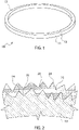
- Face surface 11 is treated with grit blasting, generally with a grit of various sizes, to lead to a surface having a series of peaks 14 and valleys 15, as shown in FIGS. 2 and 3 .
- a coating 20 is applied over the grit-blasted surface via physical vapor deposition (PVD) to a desired depth. Peaks 24 and valleys 25 are also in the coating. Then, as shown in FIG. 3 , the peaks 24 of the coating are cut off via a lapping process to form plateaus 26 separated by valleys 25.
- PVD physical vapor deposition
- the piston ring of the present invention can be manufactured to exhibit high durability during high pressure situations, yet also exhibit high lubrication properties due to the porous nature of the coating.
- the coating allows for further geometry changes to the ring gap to reduce the amount of blow-by past the piston ring.
- FIG. 4 The preferred angles for grit blasting are shown in FIG. 4 .
- An angle ⁇ of 35° to the face surface 11, and/or an angle ⁇ of 55° to the face surface 11 are used for the grit blasting process. These angles are preferred over smaller and larger angles, as they give a more regular surface effect, and allow for the creation of pockets in the surface of the ring. These pockets increase lubrication retention.
- a comparison of blast angles is shown in FIG. 6 , where using identical grit, blast angles of 35° and 55° are compared to blast angles of 5° and 30° for the face surfaces of a piston ring according to the invention. As shown in FIG. 6 , the blast angles of 35° and 55° show overall higher regularity in the surface, yet also allow for the creation of pockets in the surfaces.
- FIG. 5 shows a comparison of surface textures of the face surface for various grit sizes and combinations.
- FIGS. 7a-7e show comparisons of a surface treated with grits of various sizes and combinations, along with various blast angles.
- FIG. 7a shows the use of 320 grit and 5° and 30° blast angles. The treated surface is relatively smooth.
- FIG. 7b shows treatment with 180/220 grit at 35° and 55° blast angles. This leads to significantly rougher texture on the surface.
- FIG. 7c uses the same blast angles, but increases the grit size to 120/180. This leads to an even rougher surface but with uneven peaks and valleys.
- the preferred 120/180/220 grit combination, with the preferred angles of 35° and 55° is shown in FIG. 7d .
- the surface is uniformly roughened. Changing the blast angles to 5° and 30°, as shown in FIG. 7e , leads to less uniformity in the roughness.
- Table 1 below illustrates the comparative average roughness using the various grit sizes and blast angles.
- Table 1 Face R a R z 320 0.30 2.12 5° and 30° 120/180 0.87 6.66 35° and 55° 180/220 1.02 6.99 35° and 55° 120/180/220 0.85 6.28 35° and 55° 120/180/220 1. 99 9.05 5° and 30°
- the combination of 120/180/220 grit and the 35° and 55° blast angles gives a slightly lesser roughness in the face surface than 120/180 grit or different blast angles. This is optimal to create the best profile for performance of the rings. If the face surface is too rough, scuffing or bore marking of the cylinder liner can occur. However, for automotive applications, the removal of peaks through the lapping operation should be sufficient to eliminate this problem, as is supported by the results of the first engine test.
- having a slightly smoother face surface is optimal for uniformity of coating thickness and minimization of lapping time.
- High face roughness will require more lapping to remove during manufacturing, adding cost and resulting in a coating which fluctuates between thick and thin - thick in valleys, thin where peaks have been lapped off. This might also require increased coating thickness in order for the thin spots to be thick enough, which would add further time and cost to the manufacturing process.
- using the 120/180/220 grit leads to more surface features than the 120/180 grit in both the face and chamfer region, and these features provide superior mechanical locking strength due to the increased roughness of the substrate while still providing for a manufacturing-friendly process.
- the rings of the present invention were also tested to see if the grit blasting had any significant effect on light tightness, ring tension and the size of the free gap in the ring. 88.1 mm rings and 92.5 mm prototype pieces were tested. Piston rings having the variations of grit blasting as shown in FIGS. 7a-7e exhibited suitable light tightness and acceptable tension and ring gap sizes that varied only slightly from an untreated ring. Thus, the addition of grit up to 120 in size had negligible effects on the ring free gap and tension and no adverse effects on light tightness, yet had significant effects on the surface roughness of the ring face, giving the beneficial effects discussed above.
- Table 3 illustrates tests run on 88.1 mm piston rings and 92.5 mm prototypes that were treated with grit blasting and subjected to heating for 5 hours at 250°C to illustrate furnace conditions of a PVD chamber. As shown in the table this treatment had a negligible effect on the ring characteristics.
- Table 3 Diameter (mm) Condition Free gap (mm) CD Tension (N) Light Tightness 88.1 120/180 Blasted 12.17 22.6 good After 250°C for 5hrs 12.18 22.8 good 92.5 120/180 Blasted 14.18 21.4 good After 250°C for 5hrs 14.22 21.4 good
- FIG. 8a shows a magnified image of the ring ends of a prior art PVD piston ring, illustrating the large leak path of current PVD piston rings.
- the prior art piston ring includes a large chamfer to protect the ring ends and to reduce the likelihood of chipping of the coating at the ring ends.
- the ring ends are typically an area of the piston ring that have seen higher contact forces with the cylinder wall, and various chamfer shapes and radii have been used in an attempt to minimize any PVD coating damage in this area.
- the prior art ring as illustrated here uses a chamfer to protect the PVD coating from chipping near the ring gap, but also enlarges the gap and gas leak path of the piston ring.
- the present invention further provides advantages associated with reducing the possibility of blow-by due to the smaller ring gap with the unchamfered geometry.
- Blow-by is commonly known as the amount of combustion gases, fuel, and lubricating oils that are able to pass the piston rings. The majority of this blow-by is commonly caused by the passage created at the ring gap.
- the ring gap previously required a chamfer to protect the coating edge and avoid chipping of the PVD coating, and the chamfer greatly increases the area of the ring gap, or leak path. Therefore, any reduction in the area of the ring gap reduces the propensity for blow-by, decreasing the amount of gas that is able to pass downward into the oil sump or oil passing upwards into the combustion chamber.
- the piston ring when it is installed on the piston and compressed into the diameter of the cylinder liner, will decrease the ring gap, due to the compression of the piston ring, and this is known as the working gap of the piston ring.
- the present invention and the unique coating increases adhesion, and allows for the piston ring to be manufactured without a chamfer, thereby decreasing the piston ring gap area. Therefore, the gas leak path area is greatly decreased, further reducing the possible blow-by gases into the combustion chamber.
- FIG. 8b One example of the current invention is illustrated in FIG. 8b , where the chamfer is minimized to the lower end of manufacturability and thereby greatly reduces the leak path area when compared to the ring of FIG. 8a .
- the ring of the invention utilizes the blast process as described above, and due to the improved adhesion, the chamfer may be removed from the piston ring, since chipping is no longer a concern with the improved locking feature of the blasting process discussed in detail above.
- FIGS. 9a, 9b and 9c all illustrate the further details of the changes from the prior art production in Figs. 9a and 9b to the chamferless or unchamfered ring gap shown in FIG. 9c .
- Table 4 below further describes the reduction of the estimated leak path for one diameter of the rings from prior art as compared to an example of the subject invention.
- FIG 9a Ring Horizontal Dimension ( ⁇ m) Veritcal Dimension ( ⁇ m) Estimated Gas Leak Path ( ⁇ m 2 )
- FIG 9a -left 187 119 11127 FIG 9a -right 190 140 13300
- FIG 9a Estimated Total Gap 24427
- FIG 9b -left 158 67 5293
- FIG 9b -right 170 94 7990
- FIG 9b Estimated Total Gap 13283
- FIG 9c Estimated Total Gap 91
- FIG. 10a illustrates an enhanced image of a smaller chamfered prior art piston ring.
- the coating is a thermal spray, which is less prone to the risks of chipping due to the bonding of the molten coating, but even the smallest chamfer is significantly larger than the present invention as shown in see FIG. 10b .
- the chamfered ring includes a larger orifice area by 10% and 27% greater gas leak path.
- the smaller chamfered ring of FIG. 10a also exhibited blow-by (L/min) that was approximately 10% greater.
- FIG. 10b is an enhanced image and illustrates the sharper chamferless corner at the ring gap.
- the coating is applied by a PVD process, and this geometry is possible without concern of chipping due to the improved adhesion of the coating process discussed above.
- the chamferless corner has a width equal to or less than 0.05 mm. This is a manufacturing tolerance for the straight end, and as close to a sharp corner as possible.
- the chamferless or unchamfered rings reduce the blow-by by over 25% and reduce the working gap by 90%.
- the graph in FIG. 11 illustrates another example of the present invention, showing that the chamferless piston ring had an average decrease of 6% less blow-by than the baseline, and at higher engine RPMs, the decrease may be as high as 12%.
Landscapes
- Chemical & Material Sciences (AREA)
- Engineering & Computer Science (AREA)
- Mechanical Engineering (AREA)
- Chemical Kinetics & Catalysis (AREA)
- Materials Engineering (AREA)
- Metallurgy (AREA)
- Organic Chemistry (AREA)
- General Engineering & Computer Science (AREA)
- Pistons, Piston Rings, And Cylinders (AREA)
Claims (7)
- Procédé de fabrication d'un segment de piston, comprenant les étapes consistant à ;fournir une base de segment de piston présentant une surface frontale non chanfreinée, et un espace entre deux surfaces d'espace du segment ;grenailler la surface frontale pour créer une texture rugueuse présentant une rugosité moyenne de surface Ra de 0,3 µm-1,5 µm ;déposer un revêtement sur la surface frontale rugueuse et la surface de chanfrein par dépôt physique en phase vapeur ; etroder le revêtement pour éliminer les pics dans les surfaces sans pénétrer dans le revêtement, de sorte que les surfaces revêtues contiennent des plateaux et des vallées ; dans lequelle grenaillage est appliqué avec une grosseur de grain abrasif entre 120 et 220 ; dans lequelle grenaillage a lieu à des angles de 35° et 55° par rapport à la surface frontale du segment de piston ; dans lequelle revêtement est un nitrure de métal ou un carbone sous forme de diamant (CDA).
- Procédé selon la revendication 1, dans lequel le grain abrasif est formé d'un mélange de grains abrasifs 120, 180 et 220.
- Procédé selon la revendication 1, dans lequel le revêtement est appliqué à une épaisseur d'au moins 10 µm.
- Procédé selon la revendication 1, comprenant en outre le durcissement du segment de piston avant le grenaillage via un procédé de cémentation ou de durcissement par trempe à cœur.
- Segment de piston comprenant :un segment formé d'un matériau de base et présentant une surface frontale non chanfreinée qui est rendue rugueuse en surface jusqu'à une rugosité moyenne entre 0,3 µm-1,5 µm de Ra et deux surfaces d'espace avec un espace de segment entre elles ; etun revêtement disposé sur au moins la surface frontale, le revêtement étant déposé par dépôt physique en phase vapeur et ensuite rodé pour éliminer les pics sans pénétrer dans le revêtement, de sorte que la surface du segment de piston contient des plateaux et des vallées ; dans lequelle revêtement est formé d'un nitrure de métal ou d'un carbone sous forme de diamant (CDA).
- Segment de piston selon la revendication 5, dans lequel le segment est fait d'un acier qui a été durci par un procédé de cémentation ou de durcissement par trempe à cœur.
- Segment de piston selon la revendication 5, dans lequel un coin formé entre la surface frontale et une surface supérieure du segment présente une largeur inférieure ou égale à 0,05 mm.
Applications Claiming Priority (2)
| Application Number | Priority Date | Filing Date | Title |
|---|---|---|---|
| US15/991,493 US20190368607A1 (en) | 2018-05-29 | 2018-05-29 | Piston ring and method for manufacturing a piston ring |
| PCT/EP2019/063837 WO2019229070A1 (fr) | 2018-05-29 | 2019-05-28 | Segment de piston et procédé de fabrication d'un segment de piston |
Publications (2)
| Publication Number | Publication Date |
|---|---|
| EP3802905A1 EP3802905A1 (fr) | 2021-04-14 |
| EP3802905B1 true EP3802905B1 (fr) | 2022-07-27 |
Family
ID=66793951
Family Applications (1)
| Application Number | Title | Priority Date | Filing Date |
|---|---|---|---|
| EP19729197.4A Active EP3802905B1 (fr) | 2018-05-29 | 2019-05-28 | Segment de piston et procédé de fabrication d'un segment de piston |
Country Status (5)
| Country | Link |
|---|---|
| US (2) | US20190368607A1 (fr) |
| EP (1) | EP3802905B1 (fr) |
| CN (1) | CN112166207A (fr) |
| BR (1) | BR112020022289A2 (fr) |
| WO (1) | WO2019229070A1 (fr) |
Families Citing this family (1)
| Publication number | Priority date | Publication date | Assignee | Title |
|---|---|---|---|---|
| JP2022002857A (ja) * | 2020-06-23 | 2022-01-11 | 三菱重工業株式会社 | 加締め装置および加締め方法 |
Family Cites Families (22)
| Publication number | Priority date | Publication date | Assignee | Title |
|---|---|---|---|---|
| US3556747A (en) | 1967-11-07 | 1971-01-19 | Koppers Co Inc | Piston ring coatings for high temperature applications |
| KR890001030B1 (en) * | 1981-12-16 | 1989-04-20 | Ae Plc | Nitro-carburizing treatment method and metal ring |
| US5316321A (en) * | 1991-07-15 | 1994-05-31 | Teikoku Piston Ring Co., Ltd. | Nonferrous piston ring with hard surface treatment layer |
| JP2771947B2 (ja) * | 1994-04-21 | 1998-07-02 | 株式会社リケン | 摺動部材 |
| US5605741A (en) * | 1995-06-02 | 1997-02-25 | Dana Corporation | Hybrid face coating for piston ring |
| JP2000120869A (ja) * | 1998-10-15 | 2000-04-28 | Teikoku Piston Ring Co Ltd | 摺動部材及びその製造方法 |
| US6924005B2 (en) * | 1999-09-17 | 2005-08-02 | General Electric Company | Method for the application of a water borne, sprayable erosion coating material |
| US6491985B2 (en) * | 2000-12-20 | 2002-12-10 | Honda Giken Kogyo Kabushiki Kaisha | Method for enhancing the surface of a metal substrate |
| US20030064665A1 (en) * | 2001-09-28 | 2003-04-03 | Opel Alan E. | Apparatus to provide dry ice in different particle sizes to an airstream for cleaning of surfaces |
| EP1479946B1 (fr) * | 2003-05-23 | 2012-12-19 | Nissan Motor Co., Ltd. | Piston pour un moteur à combustion interne |
| JP4901184B2 (ja) * | 2004-11-11 | 2012-03-21 | 株式会社不二製作所 | 研磨材及び該研磨材の製造方法,並びに前記研磨材を用いたブラスト加工方法 |
| DE102008055194A1 (de) * | 2008-12-30 | 2010-07-08 | Federal-Mogul Wiesbaden Gmbh | Gleitelement |
| DE102009052587A1 (de) * | 2009-11-10 | 2011-05-12 | Federal-Mogul Burscheid Gmbh | Kolbenring |
| DE102011003254A1 (de) * | 2011-01-27 | 2012-08-02 | Federal-Mogul Burscheid Gmbh | Gleitelement, insbesondere Kolbenring, mit einer Beschichtung sowie Verfahren zur Herstellung eines Gleitelements |
| CN102777281A (zh) * | 2012-08-06 | 2012-11-14 | 南京飞燕活塞环股份有限公司 | 层叠复合涂层活塞环及其制造方法 |
| BR102013012133A2 (pt) * | 2013-05-15 | 2015-05-26 | Mahle Metal Leve Sa | Anel de pistão |
| US20150111058A1 (en) * | 2013-10-21 | 2015-04-23 | The Boeing Company | Method of coating a composite material and a coated edge of a composite structure |
| JP5965378B2 (ja) * | 2013-10-31 | 2016-08-03 | 株式会社リケン | ピストンリング及びその製造方法 |
| BR102014004402B1 (pt) * | 2014-02-25 | 2022-08-09 | Mahle Metal Leve S/A | Anel de pistão e seu processo de fabricação |
| BR102015010736B1 (pt) * | 2015-05-05 | 2021-05-25 | Mahle Metal Leve S/A | anel de pistão |
| BR102015025731B1 (pt) * | 2015-10-08 | 2021-05-18 | Mahle Metal Leve S/A | elemento deslizante |
| US10323747B2 (en) * | 2017-03-28 | 2019-06-18 | Mahle International Gmbh | Piston ring and method for manufacturing a piston ring |
-
2018
- 2018-05-29 US US15/991,493 patent/US20190368607A1/en not_active Abandoned
-
2019
- 2019-05-28 CN CN201980031602.4A patent/CN112166207A/zh active Pending
- 2019-05-28 BR BR112020022289-5A patent/BR112020022289A2/pt not_active Application Discontinuation
- 2019-05-28 WO PCT/EP2019/063837 patent/WO2019229070A1/fr active Search and Examination
- 2019-05-28 EP EP19729197.4A patent/EP3802905B1/fr active Active
-
2022
- 2022-07-05 US US17/857,673 patent/US20220333687A1/en active Pending
Also Published As
| Publication number | Publication date |
|---|---|
| US20220333687A1 (en) | 2022-10-20 |
| BR112020022289A2 (pt) | 2021-02-23 |
| EP3802905A1 (fr) | 2021-04-14 |
| WO2019229070A1 (fr) | 2019-12-05 |
| US20190368607A1 (en) | 2019-12-05 |
| CN112166207A (zh) | 2021-01-01 |
Similar Documents
| Publication | Publication Date | Title |
|---|---|---|
| US11162587B2 (en) | Piston ring and method for manufacturing a piston ring | |
| US7572344B2 (en) | Method for the production of wear-resistant sides for a keystone ring for internal combustion engine | |
| EP3056775B1 (fr) | Segment racleur d'huile combiné | |
| EP1359351B1 (fr) | Segment de piston et procede de production correspondant | |
| WO2012067084A1 (fr) | Segment de piston | |
| EP1691040A2 (fr) | Poussoir de soupape | |
| US20130174419A1 (en) | Method for producing a piston ring | |
| JP2006275269A (ja) | 組合せ摺動部材 | |
| US20220333687A1 (en) | Piston ring and method for manufacturing a piston ring | |
| JP7219776B2 (ja) | ピストンリング | |
| JP4761375B2 (ja) | 内燃機関用ピストンリング | |
| KR102466364B1 (ko) | 쇼트-피닝된 런닝-인 층을 가지는 피스톤 링 및 이를 제조하기 위한 방법(piston ring with shot-peened running-in layer and method for the production thereof) | |
| JP5860571B1 (ja) | ピストンリング | |
| RU2727466C2 (ru) | Имеющее покрытие поршневое кольцо с защитным слоем | |
| KR102155139B1 (ko) | 내연 기관 라이너 | |
| JP2006152981A (ja) | 溶射ピストンリング及びその製造方法 | |
| EP4056732A1 (fr) | Traitement de surface des segments de piston | |
| OlT et al. | Pre-surface preparation features when applying wear resistant composite sprayed coatings. | |
| JP2002332561A (ja) | ピストンリングの部分窒化方法および部分窒化ピストンリング | |
| JP2003014121A (ja) | ピストンリング | |
| US6478933B1 (en) | Method for creating surface oil reservoirs on coated iron | |
| JPH0133658B2 (fr) | ||
| JPS6357964A (ja) | ピストンリング | |
| JPH05312268A (ja) | 組合せオイルリング |
Legal Events
| Date | Code | Title | Description |
|---|---|---|---|
| STAA | Information on the status of an ep patent application or granted ep patent |
Free format text: STATUS: UNKNOWN |
|
| STAA | Information on the status of an ep patent application or granted ep patent |
Free format text: STATUS: THE INTERNATIONAL PUBLICATION HAS BEEN MADE |
|
| STAA | Information on the status of an ep patent application or granted ep patent |
Free format text: STATUS: THE INTERNATIONAL PUBLICATION HAS BEEN MADE |
|
| PUAI | Public reference made under article 153(3) epc to a published international application that has entered the european phase |
Free format text: ORIGINAL CODE: 0009012 |
|
| STAA | Information on the status of an ep patent application or granted ep patent |
Free format text: STATUS: REQUEST FOR EXAMINATION WAS MADE |
|
| 17P | Request for examination filed |
Effective date: 20201126 |
|
| AK | Designated contracting states |
Kind code of ref document: A1 Designated state(s): AL AT BE BG CH CY CZ DE DK EE ES FI FR GB GR HR HU IE IS IT LI LT LU LV MC MK MT NL NO PL PT RO RS SE SI SK SM TR |
|
| AX | Request for extension of the european patent |
Extension state: BA ME |
|
| DAV | Request for validation of the european patent (deleted) | ||
| DAX | Request for extension of the european patent (deleted) | ||
| STAA | Information on the status of an ep patent application or granted ep patent |
Free format text: STATUS: EXAMINATION IS IN PROGRESS |
|
| 17Q | First examination report despatched |
Effective date: 20210923 |
|
| GRAP | Despatch of communication of intention to grant a patent |
Free format text: ORIGINAL CODE: EPIDOSNIGR1 |
|
| STAA | Information on the status of an ep patent application or granted ep patent |
Free format text: STATUS: GRANT OF PATENT IS INTENDED |
|
| INTG | Intention to grant announced |
Effective date: 20220221 |
|
| GRAS | Grant fee paid |
Free format text: ORIGINAL CODE: EPIDOSNIGR3 |
|
| GRAA | (expected) grant |
Free format text: ORIGINAL CODE: 0009210 |
|
| STAA | Information on the status of an ep patent application or granted ep patent |
Free format text: STATUS: THE PATENT HAS BEEN GRANTED |
|
| AK | Designated contracting states |
Kind code of ref document: B1 Designated state(s): AL AT BE BG CH CY CZ DE DK EE ES FI FR GB GR HR HU IE IS IT LI LT LU LV MC MK MT NL NO PL PT RO RS SE SI SK SM TR |
|
| REG | Reference to a national code |
Ref country code: CH Ref legal event code: EP |
|
| REG | Reference to a national code |
Ref country code: DE Ref legal event code: R096 Ref document number: 602019017511 Country of ref document: DE |
|
| REG | Reference to a national code |
Ref country code: AT Ref legal event code: REF Ref document number: 1507129 Country of ref document: AT Kind code of ref document: T Effective date: 20220815 |
|
| REG | Reference to a national code |
Ref country code: IE Ref legal event code: FG4D |
|
| REG | Reference to a national code |
Ref country code: LT Ref legal event code: MG9D |
|
| REG | Reference to a national code |
Ref country code: NL Ref legal event code: MP Effective date: 20220727 |
|
| PG25 | Lapsed in a contracting state [announced via postgrant information from national office to epo] |
Ref country code: SE Free format text: LAPSE BECAUSE OF FAILURE TO SUBMIT A TRANSLATION OF THE DESCRIPTION OR TO PAY THE FEE WITHIN THE PRESCRIBED TIME-LIMIT Effective date: 20220727 Ref country code: RS Free format text: LAPSE BECAUSE OF FAILURE TO SUBMIT A TRANSLATION OF THE DESCRIPTION OR TO PAY THE FEE WITHIN THE PRESCRIBED TIME-LIMIT Effective date: 20220727 Ref country code: PT Free format text: LAPSE BECAUSE OF FAILURE TO SUBMIT A TRANSLATION OF THE DESCRIPTION OR TO PAY THE FEE WITHIN THE PRESCRIBED TIME-LIMIT Effective date: 20221128 Ref country code: NO Free format text: LAPSE BECAUSE OF FAILURE TO SUBMIT A TRANSLATION OF THE DESCRIPTION OR TO PAY THE FEE WITHIN THE PRESCRIBED TIME-LIMIT Effective date: 20221027 Ref country code: NL Free format text: LAPSE BECAUSE OF FAILURE TO SUBMIT A TRANSLATION OF THE DESCRIPTION OR TO PAY THE FEE WITHIN THE PRESCRIBED TIME-LIMIT Effective date: 20220727 Ref country code: LV Free format text: LAPSE BECAUSE OF FAILURE TO SUBMIT A TRANSLATION OF THE DESCRIPTION OR TO PAY THE FEE WITHIN THE PRESCRIBED TIME-LIMIT Effective date: 20220727 Ref country code: LT Free format text: LAPSE BECAUSE OF FAILURE TO SUBMIT A TRANSLATION OF THE DESCRIPTION OR TO PAY THE FEE WITHIN THE PRESCRIBED TIME-LIMIT Effective date: 20220727 Ref country code: FI Free format text: LAPSE BECAUSE OF FAILURE TO SUBMIT A TRANSLATION OF THE DESCRIPTION OR TO PAY THE FEE WITHIN THE PRESCRIBED TIME-LIMIT Effective date: 20220727 Ref country code: ES Free format text: LAPSE BECAUSE OF FAILURE TO SUBMIT A TRANSLATION OF THE DESCRIPTION OR TO PAY THE FEE WITHIN THE PRESCRIBED TIME-LIMIT Effective date: 20220727 |
|
| REG | Reference to a national code |
Ref country code: AT Ref legal event code: MK05 Ref document number: 1507129 Country of ref document: AT Kind code of ref document: T Effective date: 20220727 |
|
| PG25 | Lapsed in a contracting state [announced via postgrant information from national office to epo] |
Ref country code: PL Free format text: LAPSE BECAUSE OF FAILURE TO SUBMIT A TRANSLATION OF THE DESCRIPTION OR TO PAY THE FEE WITHIN THE PRESCRIBED TIME-LIMIT Effective date: 20220727 Ref country code: IS Free format text: LAPSE BECAUSE OF FAILURE TO SUBMIT A TRANSLATION OF THE DESCRIPTION OR TO PAY THE FEE WITHIN THE PRESCRIBED TIME-LIMIT Effective date: 20221127 Ref country code: HR Free format text: LAPSE BECAUSE OF FAILURE TO SUBMIT A TRANSLATION OF THE DESCRIPTION OR TO PAY THE FEE WITHIN THE PRESCRIBED TIME-LIMIT Effective date: 20220727 Ref country code: GR Free format text: LAPSE BECAUSE OF FAILURE TO SUBMIT A TRANSLATION OF THE DESCRIPTION OR TO PAY THE FEE WITHIN THE PRESCRIBED TIME-LIMIT Effective date: 20221028 |
|
| PG25 | Lapsed in a contracting state [announced via postgrant information from national office to epo] |
Ref country code: SM Free format text: LAPSE BECAUSE OF FAILURE TO SUBMIT A TRANSLATION OF THE DESCRIPTION OR TO PAY THE FEE WITHIN THE PRESCRIBED TIME-LIMIT Effective date: 20220727 Ref country code: RO Free format text: LAPSE BECAUSE OF FAILURE TO SUBMIT A TRANSLATION OF THE DESCRIPTION OR TO PAY THE FEE WITHIN THE PRESCRIBED TIME-LIMIT Effective date: 20220727 Ref country code: DK Free format text: LAPSE BECAUSE OF FAILURE TO SUBMIT A TRANSLATION OF THE DESCRIPTION OR TO PAY THE FEE WITHIN THE PRESCRIBED TIME-LIMIT Effective date: 20220727 Ref country code: CZ Free format text: LAPSE BECAUSE OF FAILURE TO SUBMIT A TRANSLATION OF THE DESCRIPTION OR TO PAY THE FEE WITHIN THE PRESCRIBED TIME-LIMIT Effective date: 20220727 Ref country code: AT Free format text: LAPSE BECAUSE OF FAILURE TO SUBMIT A TRANSLATION OF THE DESCRIPTION OR TO PAY THE FEE WITHIN THE PRESCRIBED TIME-LIMIT Effective date: 20220727 |
|
| REG | Reference to a national code |
Ref country code: DE Ref legal event code: R097 Ref document number: 602019017511 Country of ref document: DE |
|
| PG25 | Lapsed in a contracting state [announced via postgrant information from national office to epo] |
Ref country code: SK Free format text: LAPSE BECAUSE OF FAILURE TO SUBMIT A TRANSLATION OF THE DESCRIPTION OR TO PAY THE FEE WITHIN THE PRESCRIBED TIME-LIMIT Effective date: 20220727 Ref country code: EE Free format text: LAPSE BECAUSE OF FAILURE TO SUBMIT A TRANSLATION OF THE DESCRIPTION OR TO PAY THE FEE WITHIN THE PRESCRIBED TIME-LIMIT Effective date: 20220727 |
|
| PLBE | No opposition filed within time limit |
Free format text: ORIGINAL CODE: 0009261 |
|
| STAA | Information on the status of an ep patent application or granted ep patent |
Free format text: STATUS: NO OPPOSITION FILED WITHIN TIME LIMIT |
|
| PG25 | Lapsed in a contracting state [announced via postgrant information from national office to epo] |
Ref country code: AL Free format text: LAPSE BECAUSE OF FAILURE TO SUBMIT A TRANSLATION OF THE DESCRIPTION OR TO PAY THE FEE WITHIN THE PRESCRIBED TIME-LIMIT Effective date: 20220727 |
|
| 26N | No opposition filed |
Effective date: 20230502 |
|
| PG25 | Lapsed in a contracting state [announced via postgrant information from national office to epo] |
Ref country code: SI Free format text: LAPSE BECAUSE OF FAILURE TO SUBMIT A TRANSLATION OF THE DESCRIPTION OR TO PAY THE FEE WITHIN THE PRESCRIBED TIME-LIMIT Effective date: 20220727 |
|
| REG | Reference to a national code |
Ref country code: CH Ref legal event code: PL |
|
| PG25 | Lapsed in a contracting state [announced via postgrant information from national office to epo] |
Ref country code: MC Free format text: LAPSE BECAUSE OF FAILURE TO SUBMIT A TRANSLATION OF THE DESCRIPTION OR TO PAY THE FEE WITHIN THE PRESCRIBED TIME-LIMIT Effective date: 20220727 |
|
| GBPC | Gb: european patent ceased through non-payment of renewal fee |
Effective date: 20230528 |
|
| REG | Reference to a national code |
Ref country code: BE Ref legal event code: MM Effective date: 20230531 |
|
| PG25 | Lapsed in a contracting state [announced via postgrant information from national office to epo] |
Ref country code: MC Free format text: LAPSE BECAUSE OF FAILURE TO SUBMIT A TRANSLATION OF THE DESCRIPTION OR TO PAY THE FEE WITHIN THE PRESCRIBED TIME-LIMIT Effective date: 20220727 Ref country code: LU Free format text: LAPSE BECAUSE OF NON-PAYMENT OF DUE FEES Effective date: 20230528 Ref country code: LI Free format text: LAPSE BECAUSE OF NON-PAYMENT OF DUE FEES Effective date: 20230531 Ref country code: CH Free format text: LAPSE BECAUSE OF NON-PAYMENT OF DUE FEES Effective date: 20230531 |
|
| REG | Reference to a national code |
Ref country code: IE Ref legal event code: MM4A |
|
| PG25 | Lapsed in a contracting state [announced via postgrant information from national office to epo] |
Ref country code: IE Free format text: LAPSE BECAUSE OF NON-PAYMENT OF DUE FEES Effective date: 20230528 |
|
| PG25 | Lapsed in a contracting state [announced via postgrant information from national office to epo] |
Ref country code: IE Free format text: LAPSE BECAUSE OF NON-PAYMENT OF DUE FEES Effective date: 20230528 Ref country code: GB Free format text: LAPSE BECAUSE OF NON-PAYMENT OF DUE FEES Effective date: 20230528 |
|
| PG25 | Lapsed in a contracting state [announced via postgrant information from national office to epo] |
Ref country code: IT Free format text: LAPSE BECAUSE OF FAILURE TO SUBMIT A TRANSLATION OF THE DESCRIPTION OR TO PAY THE FEE WITHIN THE PRESCRIBED TIME-LIMIT Effective date: 20220727 Ref country code: FR Free format text: LAPSE BECAUSE OF NON-PAYMENT OF DUE FEES Effective date: 20230531 Ref country code: BE Free format text: LAPSE BECAUSE OF NON-PAYMENT OF DUE FEES Effective date: 20230531 |
|
| PGFP | Annual fee paid to national office [announced via postgrant information from national office to epo] |
Ref country code: DE Payment date: 20240521 Year of fee payment: 6 |