EP3801430B1 - Vorrichtung zum stützen einer person - Google Patents
Vorrichtung zum stützen einer person Download PDFInfo
- Publication number
- EP3801430B1 EP3801430B1 EP19743016.8A EP19743016A EP3801430B1 EP 3801430 B1 EP3801430 B1 EP 3801430B1 EP 19743016 A EP19743016 A EP 19743016A EP 3801430 B1 EP3801430 B1 EP 3801430B1
- Authority
- EP
- European Patent Office
- Prior art keywords
- support surface
- sub
- support
- bending
- adjustment means
- Prior art date
- Legal status (The legal status is an assumption and is not a legal conclusion. Google has not performed a legal analysis and makes no representation as to the accuracy of the status listed.)
- Active
Links
Images


Classifications
-
- A—HUMAN NECESSITIES
- A61—MEDICAL OR VETERINARY SCIENCE; HYGIENE
- A61G—TRANSPORT, PERSONAL CONVEYANCES, OR ACCOMMODATION SPECIALLY ADAPTED FOR PATIENTS OR DISABLED PERSONS; OPERATING TABLES OR CHAIRS; CHAIRS FOR DENTISTRY; FUNERAL DEVICES
- A61G5/00—Chairs or personal conveyances specially adapted for patients or disabled persons, e.g. wheelchairs
- A61G5/10—Parts, details or accessories
- A61G5/1043—Cushions specially adapted for wheelchairs
- A61G5/1045—Cushions specially adapted for wheelchairs for the seat portion
-
- A—HUMAN NECESSITIES
- A47—FURNITURE; DOMESTIC ARTICLES OR APPLIANCES; COFFEE MILLS; SPICE MILLS; SUCTION CLEANERS IN GENERAL
- A47C—CHAIRS; SOFAS; BEDS
- A47C7/00—Parts, details, or accessories of chairs or stools
- A47C7/02—Seat parts
- A47C7/14—Seat parts of adjustable shape; elastically mounted ; adaptable to a user contour or ergonomic seating positions
- A47C7/144—Seat parts of adjustable shape; elastically mounted ; adaptable to a user contour or ergonomic seating positions with array of movable supports
-
- A—HUMAN NECESSITIES
- A47—FURNITURE; DOMESTIC ARTICLES OR APPLIANCES; COFFEE MILLS; SPICE MILLS; SUCTION CLEANERS IN GENERAL
- A47C—CHAIRS; SOFAS; BEDS
- A47C7/00—Parts, details, or accessories of chairs or stools
- A47C7/02—Seat parts
- A47C7/28—Seat parts with tensioned springs, e.g. of flat type
-
- A—HUMAN NECESSITIES
- A61—MEDICAL OR VETERINARY SCIENCE; HYGIENE
- A61G—TRANSPORT, PERSONAL CONVEYANCES, OR ACCOMMODATION SPECIALLY ADAPTED FOR PATIENTS OR DISABLED PERSONS; OPERATING TABLES OR CHAIRS; CHAIRS FOR DENTISTRY; FUNERAL DEVICES
- A61G7/00—Beds specially adapted for nursing; Devices for lifting patients or disabled persons
- A61G7/05—Parts, details or accessories of beds
- A61G7/057—Arrangements for preventing bed-sores or for supporting patients with burns, e.g. mattresses specially adapted therefor
- A61G7/0573—Arrangements for preventing bed-sores or for supporting patients with burns, e.g. mattresses specially adapted therefor with mattress frames having alternately movable parts
-
- B—PERFORMING OPERATIONS; TRANSPORTING
- B60—VEHICLES IN GENERAL
- B60N—SEATS SPECIALLY ADAPTED FOR VEHICLES; VEHICLE PASSENGER ACCOMMODATION NOT OTHERWISE PROVIDED FOR
- B60N2/00—Seats specially adapted for vehicles; Arrangement or mounting of seats in vehicles
- B60N2/70—Upholstery springs ; Upholstery
- B60N2/7023—Coach-like constructions
- B60N2/7035—Cushions
- B60N2/7047—Springs
-
- B—PERFORMING OPERATIONS; TRANSPORTING
- B60—VEHICLES IN GENERAL
- B60N—SEATS SPECIALLY ADAPTED FOR VEHICLES; VEHICLE PASSENGER ACCOMMODATION NOT OTHERWISE PROVIDED FOR
- B60N2/00—Seats specially adapted for vehicles; Arrangement or mounting of seats in vehicles
- B60N2/70—Upholstery springs ; Upholstery
- B60N2/72—Attachment or adjustment thereof
Definitions
- the invention relates to a device for supporting persons.
- the person using the device can be supported while sitting or recumbent.
- a field of application of the invention is aimed at improving the comfortableness of the person in question, in particular when the person needs to be supported for a long period of time, such as in the transport sector, in particular truck drivers and couriers.
- Another field of application is aimed at medical effects, in particular counteracting decubitus (bedsores), such as for sitting or recumbent persons.
- Another field of application is occupational therapy.
- the invention provides a support device having a main support surface for the body of a person, comprising an auxiliary device for influencing the shape of the main support surface, wherein the auxiliary device comprises:
- the support device provides the possibility of adjusting either the shape of the main support surface, or the distribution of the forces exerted on it by the user, in response to the actual condition.
- the combination of adjustment means and electromotor, which preferably is a stepper motor, for each sub-support surface, the monitoring means and the bending plates make it possible to influence, in particular adjust the sub-support surfaces and consequently the main support surface, accurately.
- the occupation of space in the vertical sense can then be kept limited as the electromotor and the bending plate in the vertical sense can at least partially coincide, the electromotor can at least be partially surrounded by the bending plate, as it were.
- the bending plate is positioned with the concave side at its bottom side.
- the support elements each comprise two bending plates situated one above the other, which face each other with their concave sides, wherein the electromotor is situated between both bending plates. In that case the electromotor adds no constructional height to the support element.
- the electromotor is attached to one end of the bending plate or to adjacent ends of both bending plates to be jointly displaced with them,
- the support device comprises a frame and
- the bending elements each comprise an elastically bendable beam
- the beam is clamped at one end and free at the other end.
- the electromotor is attached to the beam.
- the support element comprises a bending plate on one side of the electromotor only
- that support plate is attached to the beam.
- the support plate which is situated on one of either sides of the electromotor can be attached to the beam.
- the location of attachment is in the center (the longitudinal center between both ends) of the respective bending plate.
- the location of attachment can be at the free end of the beam, as a result of which the displacement under vertical force is as large as possible, which can be conducive to a fine-tuning.
- the bending plate is, or both bending plates are, positioned such that the horizontal distance between both ends of each bending plate is changed when the respective bending plate bends. The center of each bending plate is then vertically displaced upon bending.
- a stop can be arranged for limiting the vertical downward travel of the bending element.
- the sub-support surface can be integrally formed with the bending plate.
- each support element is flat, in particular in the horizontal plane. That way the curvature of a bending plate of which the convex side is facing upward, can be made less noticeable to a person supported on the main support surface.
- the flat sub-support surface can be integrally formed with the respective bending plate.
- the flat sub-support surface can be part of a small plate added to the respective bending plate, which small plate preferably is attached to the bending plate in a relatively movable fashion. The small plate can then be attached to the respective bending plate so as to hinge, preferably so as to hinge in all directions (universally), such as with a ball hinge. The small plate is then in body-tracing position, which may be pleasant to the user.
- the invention provides a support device having a main support surface for the body of a person, comprising an auxiliary device for influencing the shape of the main support surface, wherein the auxiliary device comprises:
- control unit is configured for repeatedly receiving from the monitoring means, the data for each of the support elements of which the adjustment means are controlled, and each time on the basis of those data calculating the force exerted on the sub-support surface and then once more calculating the average force and making the said comparison, and subsequently on the basis of the outcome of said comparison controlling the adjustment means once more.
- control unit is configured for allowing the user to make a selection of the support elements that do or do not have to be controlled by the control unit during use.
- the control unit can then be configured for putting the support elements selected not to be controlled, in the lowest position, at least in a low position as a result of which they will be able to remain free from being loaded by the user.
- a user wishing to off-load a particular part of his body such as may for instance be the case when the user has a bedsore, can place the support elements that would otherwise provide support to the area of that spot in the lowest position in order to ensure that during use that area will not or hardly be loaded.
- this may be an advantageous option.
- control unit is configured for also after to an at least acceptable extent achieving an evenly distributed load, continuing the said control process, to detect the person's displacement relative to the sub-support surfaces and controlling the adjustment means accordingly to a new roughly evenly distributed loaded condition of the sub-support surfaces.
- the support elements can each comprise an elastically bendable plate that is connected to the adjustment means to be adjusted thereby in its the extent of bending,
- the adjustment means can each comprises an electromotor that is situated on the concave side of the bending plate.
- the support device can be equipped with one or more of the features described in claims 1-12.
- the invention provides a non-therapeutic method for influencing the shape of a main support surface of a support device for a person, using an auxiliary device for influencing the shape of the main support surface, which auxiliary device comprises:
- the series of steps c)-f) can be carried out repeatedly, with short intervals that are in the order of (for instance a part of a second) the period of time required for measuring, calculating and operating the adjustment means, which adjustment means preferably comprise a stepper motor. Said intervals can be a part of a second. Ultimately, a situation could then be achieved in which all loaded support elements are roughly evenly loaded. Pressure peaks can be prevented.
- the series of steps c)-f) are carried out for as long as the person is supported on the main support surface. That way a change in the posture and/or position of the person can be anticipated.
- a delay may have been set, for instance of a few seconds, in order for the system not to seem too unquiet to the user.
- step c) only the actual force exerted on the sub-support surfaces that are used by the person is calculated.
- changing position that may be a different group than previously.
- step a) the sub-support surfaces are set at equal height. This may be a height in between the maximum and minimum height.
- step c) prior to step c), in particular prior to step b), the user makes a selection of the support elements that do or do not need to be controlled by the control unit during use. The user can then direct the control unit to place support elements selected not to be controlled in the lowest position. Those will not be loaded by the user's body, which may be advantageous when the user wishes to off-load a possible support surface of his body.
- the wheelchair 1 in figure 1 is an example of an application of a support device according to the invention.
- the support device according to the invention can be used in any situation in which a person needs to be supported in the sitting or recumbent position: both in chairs and in beds.
- the wheelchair 1 comprises a frame 2 supported by wheels, on which frame a backrest 3 and a seat 4 are arranged. On the seat 4 a cushion 5 is placed, in which an example of a support device 10 according to the invention is incorporated.
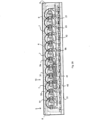
- the support device 10 comprises a group of support elements 6 that are positioned in a number of series, wherein the consecutive series are shifted relative to each other along half a length of the support element 6.
- the group of support elements is surrounded all around by a band 8 of synthetic foam, of which only two sides are shown.
- the support elements 6 are attached to a rigid base plate 40 on which slightly above it a printed circuit board 41 including connections 42 is also situated.
- the support elements 6 each form a sub-support surface 7, wherein the sub-support surfaces 7 are covered by a layer of foam rubber 30 and the whole is surrounded by an enveloping 31, see figure 2B , which enveloping forms a main support surface.
- the main support surface and the layer of foam rubber is supported on the sub-support surface.
- the support device is provided with a programmable control unit 100, provided with a power source, such as a battery.
- a support element 6 is shown in further detail in figures 3A-C .
- the support element 6 comprises two elastically bendable bending plates 9a, 9b, which are bent upward and downward, respectively, in a convex fashion.
- the bending plates 9a,b can be manufactured of synthetic material, such as a nylon.
- a space A is formed between concave sides of the bending plates 9a,b, in which space an electromotor is accommodated, in the example stepper motor 14.
- the stepper motor 14, which is connected to a connector 42 on the printed circuit board 41 via wiring 26 and to the control unit 100 via the printed circuit board 41, is attached to a cut-away housing 16, and drives a shaft 15 in horizontal directions B1,2.
- the end 15a of the shaft 15 is attached in an end block 18, with which the beaded edge-shaped ends 19a of the bending plate 9a and the beaded edge-shaped ends 19b of the bending plate 9b are connected so as to hinge in the vertical plane.
- the other ends of the bending plates 9a and 9b are similarly connected to the end block 17 which is integral with the housing 16.
- the lowermost bending plate 9b (considered both in the longitudinal direction and in the width direction) is attached by a bolt connection 20 near the free end of a flat, beam 21 clamped on one side, which beam is elastically bendable in the vertical plane.
- the beam 21 is attached to a support block 23 in a rigidly clamped fashion by means of screws 24, which support block is rigidly attached to the rigid plate 40.
- the bolt connection 20 has a head 20a extending downward, which is situated above a stop (not shown) that is attached to the plate 40 and extends upwards therefrom. This stop limits the downward displacement of the free end of the beam 21.
- a resistance strain gauge 22 is arranged on the beam 21, which gauge is connected to a connector 42 on the printed circuit board 41 via wiring 25, and to the control unit 100 via the printed circuit board 41.
- FIGS 3D-F it is shown how by means of operating the support elements 6 by the control unit 100, the vertical distance between the top and bottom of the bending plate 9a and bending plate 9b, respectively, can be influenced.
- the shaft 15 is fully retracted in direction B2 into the stepper motor 14.
- the height h3 of the support element 6 is then at its maximum.
- the stepper motor 14 extends the shaft 15 (direction B1) the horizontal distance between the end blocks 17 and 18 will be increased, as a result of which the height h2 of the support element 6 decreases, see figure 3E .
- the shaft 15 has been extended to its maximum, figure 3F , the height h1 is at its minimum.
- the shaft 15 is retracted (direction B2) the height will increase again.
- Figure 4 shows an embodiment of the bending plate 9a, in which the sub-support surface 7 is formed by a small flat plate 50, which at the bottom side is provided with a bearing ball 51, that is accommodated so as to be rotatable, directions C, in bearing cavity 52, that is integrally formed with the bending plate 9a.
- the control unit 100 will control the stepper motors 14 of all support elements 6 into a retracted position of the shafts 15.
- the related condition of the resistance strain gauges 22 is stored as zero-setting.
- the support device has then been calibrated or "zeroed", also see the chart in figure 5 . Zeroing or calibrating is also possible by fully extending all shafts.
- the control unit 100 will subsequently control the stepper motors 14 for extending the shafts 15 to half an extension length. The support device is then ready for use.
- the load on the support elements 6 will result in the respective beam 21 bending through, causing a change in the condition of the resistance strain gauge 22 attached to it.
- This change is detected in the control unit 100, which by using the data of the resistance strain gauge calculates the force exerted on the beam 21. This is done for all loaded support elements.
- the control unit 100 subsequently calculates the arithmetic average value of those forces.
- the force F1,F2, ...Fn calculated for each loaded support element is then compared to the calculated average force Fmean (in the figure called Fm). If the outcome is that the force on the support element exceeds Fmean, then the stepper motor for that support element is controlled so as to extend the shaft one step, for instance 2 mm. As a consequence the convexity of both bending plates 9a,b will decrease, as a result of which the sub-support surface 7 of that support element 6 will come to lie lower. If the outcome is that the force on the support element is smaller than Fmean, then the stepper motor for that support element is controlled so as to retract the shaft one step.
- Fm the calculated average force Fmean
- Controlling the electromotors 14 of the support elements 6 after the step of comparing the calculated forces F1,F2...Fn to the Fmean may in one embodiment take place in groups, such as that the wanted support elements of a first group of adjacent support elements are first operated and subsequently the wanted support elements of a second group, etc. This can be done in quick succession.
- the power required can be kept limited, which is advantageous when using a battery for the power supply of the electromotors.
Landscapes
- Engineering & Computer Science (AREA)
- Aviation & Aerospace Engineering (AREA)
- Transportation (AREA)
- Mechanical Engineering (AREA)
- Health & Medical Sciences (AREA)
- Life Sciences & Earth Sciences (AREA)
- Animal Behavior & Ethology (AREA)
- General Health & Medical Sciences (AREA)
- Public Health (AREA)
- Veterinary Medicine (AREA)
- Nursing (AREA)
- Invalid Beds And Related Equipment (AREA)
Claims (16)
- Stützvorrichtung (10) mit einer Hauptstützfläche für den Körper einer Person, umfassend eine Hilfsvorrichtung zum Beeinflussen der Form der Hauptstützfläche, wobei die Hilfsvorrichtung umfasst:- eine Gruppe von Stützelementen (6) zum Abstützen der Hauptstützfläche, wobei die Gruppe auf der Seite der Hauptstützfläche positioniert ist, die von der den Körper tragenden Seite abgewandt ist,- wobei die Stützelemente jeweils eine Unterstützfläche (7) umfassen,- Einstellmittel für jede Unterstützfläche zum Beeinflussen der Höhe jeder Unterstützfläche (7) relativ zu einer Referenzebene und infolgedessen der lokalen Höhe der Hauptstützfläche,
gekennzeichnet durch- Überwachungsmittel für jede Unterstützfläche zum Überwachen der Höhe der jeweiligen Unterstützfläche und/oder der von der Person auf die jeweilige Unterstützfläche ausgeübten Kraft, und- eine programmierbare Steuereinheit (100) zum Steuern der Einstellmittel als Reaktion auf von den Überwachungsmitteln empfangene Daten,- wobei die Stützelemente (6) jeweils eine elastisch biegbare Platte (9a) umfassen, die mit den Einstellmitteln verbunden ist, um dadurch in ihrem Ausmaß der Biegung beeinflusst zu werden,- wobei die Biegeplatte (9a) mit der Unterstützfläche (7) verbunden ist, um ihre Höhe in Abhängigkeit von dem durch die Einstellmittel auferlegten Ausmaß der Biegung zu beeinflussen, wobei die Einstellmittel jeweils einen Elektromotor umfassen, der sich auf der konkaven Seite der Biegeplatte (9a) befindet, wobei der Elektromotor vorzugsweise ein Schrittmotor (14) ist. - Vorrichtung nach Anspruch 1,- wobei die Stützelemente (6) jeweils zwei übereinander gelegene Biegeplatten (9a, 9b) umfassen, die einander mit ihren konkaven Seiten zugewandt sind, wobei sich der Elektromotor zwischen beiden Biegeplatten (9a, 9b) befindet.
- Vorrichtung nach Anspruch 1 oder 2,- wobei der Elektromotor an einem Ende der Biegeplatte (9a) oder an nebeneinanderliegenden Enden beider Biegeplatten (9a, 9b) befestigt ist, um gemeinsam mit ihnen verschoben zu werden,- wobei die Einstellmittel ferner ein Antriebselement umfassen, das von dem Elektromotor angetrieben wird und mit einem Ende in einer Antriebsverbindung mit dem anderen Ende der Biegeplatte (9a) oder den anderen Enden der Biegeplatten (9a, 9b) steht,- wobei, vorzugsweise, das Antriebselement ein Schaft (15) ist, der vom Elektromotor linear verschoben wird.
- Vorrichtung nach einem der Ansprüche 1 bis 3, umfassend- einen Rahmen (40) und- Biegeelemente, die in der vertikalen Ebene elastisch biegbar sind und mit denen die jeweiligen Stützelemente (6) an dem Rahmen befestigt sind,- wobei die Überwachungsmittel Sensoren zum Überwachen der Biegung der Biegeelemente und/oder der Kraft die der Benutzer auf die Biegeelemente ausübt, umfasst,- wobei die Sensoren mit der Steuereinheit (100) verbunden sind, um Signale an sie auszugeben, die die Biegung der Biegeelemente und/oder die Kraft die der Benutzer auf die Biegeelemente ausübt, anzeigen,- wobei die Steuereinheit (100) dazu eingerichtet ist, auf der Grundlage der von den Sensoren empfangenen Signale die auf die Biegeelemente ausgeübte Kraft und die damit verbundene vertikale Position des Stützelements zu berechnen, wobei die Vorrichtung vorzugsweise mit einem Anschlag zum Begrenzen der vertikalen Abwärtsbewegung des Biegeelements versehen ist,- wobei, vorzugsweise, die Biegeelemente jeweils eine elastisch biegbare Stange (21) umfassen, und- wobei die Sensoren jeweils einen Widerstandsdehnungsmessstreifen (22) umfassen, der auf der Stange (21) angeordnet ist,in welchem Fall, vorzugsweise, die Stange (21) an einem Ende eingespannt und am anderen Ende frei ist.
- Vorrichtung nach Anspruch 4,- wobei die Stützelemente (6) nur auf einer Seite des Elektromotors mit einer Biegeplatte (9a) versehen sind, und- wobei der Elektromotor an der Stange (21) befestigt ist, oder- wobei die Stützelemente (6) auf beiden Seiten des Elektromotors mit einer Biegeplatte (9a, 9b) versehen sind, wobei eine der Biegeplatten (9b) an der Stange (21) befestigt ist,- wobei sich, vorzugsweise, die Befestigungsstelle in der Mitte der jeweiligen Biegeplatte (9b) befindet.
- Vorrichtung nach Anspruch 5,- wobei die Stange (21) an einem Ende eingespannt und am anderen Ende frei ist; und- wobei sich die Befestigungsstelle am freien Ende der Stange (21) befindet.
- Vorrichtung nach einem der vorhergehenden Ansprüche,- wobei die Biegeplatte (9a) oder beide Biegeplatten (9a, 9b) derart positioniert ist bzw. sind, dass sich der horizontale Abstand zwischen beiden Enden jeder Biegeplatte bei Änderung des Ausmaßes der Biegung der betreffenden Biegeplatte ändert.
- Vorrichtung nach einem der vorhergehenden Ansprüche,- wobei die Unterstützfläche (7) von jedem Stützelement (6) flach ist, insbesondere in der horizontalen Ebene,- wobei, vorzugsweise, die flache Unterstützfläche (7) einstückig mit der jeweiligen Biegeplatte (9a) ausgebildet ist, oder- die flache Unterstützfläche (7) Teil einer kleinen Platte (50) ist, die zur jeweiligen Biegeplatte (9a) hinzugefügt ist, wobei die kleine Platte (50) vorzugsweise an der Biegeplatte in einer relativ beweglichen Weise befestigt ist, in welchem Fall, vorzugsweise,die kleine Platte (50) an der jeweiligen Biegeplatte (9a) derart befestigt ist, dass sie abklappt, vorzugsweise dass sie in allen Richtungen abklappt.
- Stützvorrichtung (10) nach einem der vorhergehenden Ansprüche, wobei die konkave Seite der Biegeplatte (9a), die mit der Unterstützfläche (7) verbunden ist und dadurch getragen wird, die Unterseite ist.
- Stützvorrichtung (10) nach einem der vorhergehenden Ansprüche,- wobei die Überwachungsmittel zum Überwachen eines Parameters eingerichtet sind, der die Kraft anzeigt, die von der Person auf jede Unterstützfläche (7) ausgeübt wird,- wobei die programmierbare Steuereinheit (100) mit den Überwachungsmitteln verbunden ist, um die den Parameter betreffenden Daten zu empfangen,- wobei die Steuereinheit (100) dazu eingerichtet ist:- auf der Grundlage der von den Überwachungsmitteln empfangenen Daten die Einzelkraft F1, F2, ..., Fn zu berechnen, die von der Person auf jede Unterstützfläche (7) ausgeübt wird,- den Mittelwert "Fmean" der berechneten Kräfte F1, F2, ..., Fn zu berechnen,- die berechneten Kräfte F1, F2, ..., Fn mit dem berechneten Fmean zu vergleichen, und- auf der Grundlage des Ergebnisses des Vergleichs die Einstellmittel zum Ändern der Höhe der jeweiligen Unterstützfläche (7) zu steuern, um im Falle einer Differenz zwischen der berechneten Einzelkraft auf eine Unterstützfläche und dem berechneten Fmean diese Differenz zu verringern,- wobei die Steuervorrichtung (100) vorzugsweise dazu eingerichtet ist, in die Berechnungen nur diejenigen Unterstützflächen (7) einzubeziehen, die die Person tatsächlich belastet.
- Stützvorrichtung (10) nach Anspruch 10,- wobei die Steuereinheit (100) dazu eingerichtet ist, wiederholt von den Überwachungsmitteln die Daten für jedes der Stützelemente (6), deren Einstellmittel gesteuert werden, zu empfangen und jedes Mal auf der Grundlage dieser Daten die auf die Unterstützfläche ausgeübte Kraft zu berechnen und dann erneut die Mittelwerts-kraft zu berechnen und den Vergleich vorzunehmen und anschließend auf der Grundlage des Ergebnisses des Vergleichs die Einstellmittel erneut zu steuern, und/oder- wobei die Steuereinheit (100) dazu eingerichtet ist, die Einstellmittel des einen Stützelements koordiniert mit dem Steuern der Einstellmittel von mindestens einem anderen Stützelement (6), vorzugsweise einem benachbarten Stützelement, zu steuern, und/oder- wobei die Steuereinheit (100) dazu eingerichtet ist, dem Benutzer die Möglichkeit zu bieten, eine Auswahl der Stützelemente (6) zu treffen, die von der Steuereinheit (100) während des Gebrauchs gesteuert werden sollen oder nicht gesteuert werden sollen, wobei sie vorzugsweise dazu eingerichtet ist, die Stützelemente (6), die ausgewählt werden um nicht gesteuert zu werden, in die niedrigste Position zu versetzen, und/oder- wobei die Steuereinheit (100) dazu eingerichtet ist, auch nach dem Erreichen zumindest in einem akzeptablen Umfang einer gleichmäßig verteilten Last den Steuerprozess fortzusetzen, um Verlagerungen der Person relativ zu den Unterstützflächen (7) zu erkennen und die Einstellmittel entsprechend auf einen neuen Zustand einer gleichmäßig verteilten Belastung der Unterstützflächen (7) zu regulieren.
- Stützvorrichtung (10) nach Anspruch 10 oder 11,- wobei die Stützelemente (6) jeweils eine elastisch biegbare Platte (9a) umfassen, die mit den Einstellmitteln verbunden ist, um dadurch in ihrem Ausmaß der Biegung eingestellt zu werden,- wobei die Biegeplatte (9a) mit der Unterstützfläche (7) verbunden ist, um ihre Höhe in Abhängigkeit vom Ausmaß der Biegung zu beeinflussen,- wobei, vorzugsweise, die Einstellmittel jeweils einen Elektromotor umfassen, der auf der konkaven Seite der Biegeplatte (9a), insbesondere auf der Unterseite der Biegeplatte (9a), positioniert ist.
- Kissen oder Matratze, das/die mit einer Stützvorrichtung (10) nach einem der vorhergehenden Ansprüche versehen ist.
- Nichttherapeutisches Verfahren zum Beeinflussen der Form einer Hauptstützfläche einer Stützvorrichtung (10) für eine Person, insbesondere einer Stützvorrichtung (10) nach einem der Ansprüche 1 bis 13, unter Verwendung einer Hilfsvorrichtung zum Beeinflussen der Form der Hauptstützfläche, wobei die Hilfsvorrichtung umfasst:- eine Gruppe von Stützelementen (6) zum Abstützen der Hauptstützfläche, wobei die Gruppe auf der Seite der Hauptstützfläche positioniert ist, die von der den Körper tragenden Seite abgewandt ist,- wobei die Stützelemente (6) jeweils eine Unterstützfläche (7) umfassen,- wobei Einstellmittel für jede Unterstützfläche (7) zum Beeinflussen, insbesondere Einstellen, der Höhe jeder Unterstützfläche (7) relativ zu einer Referenzebene und infolgedessen der lokalen Höhe der Hauptstützfläche vorhanden sind; wobei die Einstellmittel von einer programmierbaren Steuereinheit (100) betätigt werden können,- wobei die Form der Hauptstützfläche beeinflusst wird, indem die Höhe von mindestens einer Anzahl der Unterstützflächen (7) relativ zu einer Referenzebene und infolgedessen die lokale Höhe der Hauptstützfläche beeinflusst, insbesondere eingestellt, wird,- wobei das Verfahren die folgenden Schritte umfasst:a) Ermöglichen, dass die Steuereinheit (100) die Einstellmittel betätigt, um jede Unterstützfläche (7) in eine vorgegebene Position zu bringen;b) Ermöglichen, dass eine Person auf der Hauptstützfläche Platz nimmt;c) Berechnen nach einer Zeitspanne, beispielsweise 10 Sekunden, pro Unterstützfläche (7) der (momentanen) Kräfte F1, F2, ..., Fn, die die Person auf jede der Unterstützflächen (7) ausübt;d) Berechnen des Mittelwerts "Fmean" der berechneten Kräfte F2, F1, ..., Fn;e) Vergleichen der berechneten Kräfte F1, F2, ..., Fn mit dem berechneten Fmean, und- Steuern auf der Grundlage des Ergebnisses des Vergleichs der Einstellmittel zum Ändern der Höhe der jeweiligen Unterstützfläche (7), um im Falle einer Differenz zwischen der berechneten Einzelkraft auf eine Unterstützfläche und dem berechneten Fmean diese Differenz zu verringern,- wobei, vorzugsweise, die Schrittfolge c) bis f) wiederholt ausgeführt wird, in welchem Fall, vorzugsweise, die Schrittfolge c) bis f) solange ausgeführt wird, wie die Person auf der Hauptstützfläche gestützt wird.
- Verfahren nach Anspruch 14,- wobei in Schritt c) die ausgeübte momentane Kraft nur für diejenigen Unterstützflächen (7) berechnet wird, die die Person belastet, und/oder- wobei in Schritt a) die Unterstützflächen (7) auf eine gleiche Höhe eingestellt werden, insbesondere auf eine Höhe zwischen der geringsten und der größten Höhe, und/oder- wobei die Steuereinheit (100) in Schritt f) die Einstellmittel von verschiedenen Unterstützflächen (7) asynchron betätigt, in welchem Fall, vorzugsweise, die Steuereinheit (100) in Schritt f) die Einstellmittel von benachbarten Unterstützflächen (7) asynchron betätigt, insbesondere eine nach der anderen.
- Verfahren nach Anspruch 14 oder 15, wobei vor Schritt c), insbesondere vor Schritt b), eine Auswahl der Stützelemente (6) getroffen wird, die von der Steuereinheit (100) während des Gebrauchs gesteuert werden sollen oder nicht gesteuert werden sollen, wobei, vorzugsweise, die Steuereinheit (100) die Stützelemente (6), die ausgewählt werden, um nicht gesteuert zu werden, in die niedrigste Position, zumindest eine niedrige Position, versetzt, in der sie der Benutzer nicht oder nur in einem minimalen Umfang belasten kann.
Applications Claiming Priority (2)
| Application Number | Priority Date | Filing Date | Title |
|---|---|---|---|
| NL2021000A NL2021000B1 (nl) | 2018-05-29 | 2018-05-29 | Inrichting voor het ondersteunen van personen |
| PCT/NL2019/050305 WO2019231317A1 (en) | 2018-05-29 | 2019-05-28 | Device for supporting a person |
Publications (3)
| Publication Number | Publication Date |
|---|---|
| EP3801430A1 EP3801430A1 (de) | 2021-04-14 |
| EP3801430C0 EP3801430C0 (de) | 2025-05-21 |
| EP3801430B1 true EP3801430B1 (de) | 2025-05-21 |
Family
ID=63684383
Family Applications (1)
| Application Number | Title | Priority Date | Filing Date |
|---|---|---|---|
| EP19743016.8A Active EP3801430B1 (de) | 2018-05-29 | 2019-05-28 | Vorrichtung zum stützen einer person |
Country Status (5)
| Country | Link |
|---|---|
| US (2) | US11786422B2 (de) |
| EP (1) | EP3801430B1 (de) |
| CN (1) | CN112888411B (de) |
| NL (1) | NL2021000B1 (de) |
| WO (1) | WO2019231317A1 (de) |
Families Citing this family (1)
| Publication number | Priority date | Publication date | Assignee | Title |
|---|---|---|---|---|
| NL2038202B1 (en) | 2024-07-11 | 2026-01-29 | Hans Voorwinde Beheer B V | Support device and method for supporting a person |
Family Cites Families (31)
| Publication number | Priority date | Publication date | Assignee | Title |
|---|---|---|---|---|
| GB1377738A (en) * | 1971-07-31 | 1974-12-18 | Avery Ltd W T | Force measuring devices |
| US6392550B1 (en) * | 2000-11-17 | 2002-05-21 | Ford Global Technologies, Inc. | Method and apparatus for monitoring driver alertness |
| US20030109817A1 (en) | 2001-12-11 | 2003-06-12 | Shimon Berl | Supplementary knee support brace |
| US6880886B2 (en) | 2002-09-12 | 2005-04-19 | Steelcase Development Corporation | Combined tension and back stop function for seating unit |
| US10512575B2 (en) * | 2007-02-06 | 2019-12-24 | Deka Products Limited Partnership | Dynamic support apparatus |
| JP4254295B2 (ja) * | 2003-03-25 | 2009-04-15 | アイシン精機株式会社 | 着座検知装置 |
| NL1028539C2 (nl) * | 2005-03-14 | 2006-09-18 | Hans Voorwinde Beheer B V | Inrichting voor het voorkomen van decubitus. |
| DE202006003948U1 (de) * | 2006-03-14 | 2006-07-06 | Achilles, Hans-Jürgen | Druckautomatik für therapeutische Einkammerkissen |
| DE102007053119A1 (de) * | 2007-11-08 | 2009-05-14 | Bayerische Motoren Werke Aktiengesellschaft | Verfahren und Vorrichtung zum Einstellen eines Sitzes sowie Sitz |
| US8752222B2 (en) * | 2008-10-13 | 2014-06-17 | George Papaioannou | Adaptable surface for use in beds and chairs to reduce occurrence of pressure ulcers |
| US8539627B2 (en) * | 2010-01-27 | 2013-09-24 | Tokai Rubber Industries, Ltd. | Body position and pressure control apparatus |
| DE102012201331A1 (de) * | 2011-03-02 | 2012-09-06 | Ford Global Technologies, Llc | Sitz, insbesondere Fahrzeugsitz, mit einem Formänderungselement sowie Verfahren zum Ansteuern eines Formänderungselements eines Sitzes |
| US9009898B2 (en) * | 2011-11-21 | 2015-04-21 | Paramount Bed Co., Ltd. | Mattress, pressure sensor calibration method, and bed device |
| IN2014DN06830A (de) | 2012-01-26 | 2015-05-22 | Huntleigh Technology Ltd | |
| US9125493B2 (en) * | 2012-01-31 | 2015-09-08 | Backjoy Orthotics, Llc | Seat cushion with flexible contouring |
| WO2013123119A1 (en) * | 2012-02-15 | 2013-08-22 | Stryker Corporation | Patient support apparatus and controls therefor |
| US9486160B2 (en) * | 2012-06-09 | 2016-11-08 | Xsensor Technology Corporation | Analysing seating using pressure sensors |
| CN107264364B (zh) * | 2012-11-28 | 2019-06-21 | 提爱思科技股份有限公司 | 车用座椅 |
| JP6353443B2 (ja) * | 2013-06-06 | 2018-07-04 | 株式会社イトーキ | 椅子 |
| FR3013328B1 (fr) * | 2013-11-20 | 2017-08-04 | Zodiac Seats France | Siege d'avion auto-ajustable a la morphologie d'un passager |
| US9955795B2 (en) * | 2014-06-05 | 2018-05-01 | Matthew W. Krenik | Automated bed and method of operation thereof |
| WO2016018914A2 (en) * | 2014-07-28 | 2016-02-04 | Deka Products Limited Partnership | Dynamic support apparatus |
| US10293718B1 (en) * | 2016-06-22 | 2019-05-21 | Apple Inc. | Motion control seating system |
| US10549662B2 (en) * | 2016-12-22 | 2020-02-04 | GM Global Technology Operations LLC | Climate control system and method for heating and cooling a seat of a vehicle based on an occupant pressure distribution, and a method of manufacturing a seat climate control system |
| US10974619B2 (en) * | 2017-03-28 | 2021-04-13 | Ts Tech Co., Ltd. | Vehicle seat and passenger selection system |
| US11089881B2 (en) * | 2017-12-15 | 2021-08-17 | Nanthealth, Inc. | Modular mattress and bedframe system with surface positioning actuators |
| EP3930654B1 (de) * | 2019-02-26 | 2023-09-20 | Hill-Rom Services, Inc. | Patientenpositionierungsvorrichtung und matratze |
| US12115116B2 (en) * | 2019-05-14 | 2024-10-15 | Ige, Llc | Support system including layers of spacer fabric and non-viscoelastic pressure relief material, and method for measuring pressure and pressure distribution properties of a support system |
| AT523112A1 (de) * | 2019-10-16 | 2021-05-15 | Zenzmaier Cornelia | Verfahren zur Orts- und Lagebestimmung eines Beckens einer Person |
| US20240197256A1 (en) * | 2020-12-30 | 2024-06-20 | Seoul National University Hospital | Smart mattress |
| US20220212578A1 (en) * | 2021-01-04 | 2022-07-07 | Lars Roulund | Ergonomic seating system and method of use |
-
2018
- 2018-05-29 NL NL2021000A patent/NL2021000B1/nl active
-
2019
- 2019-05-28 US US17/058,780 patent/US11786422B2/en active Active
- 2019-05-28 CN CN201980050317.7A patent/CN112888411B/zh active Active
- 2019-05-28 WO PCT/NL2019/050305 patent/WO2019231317A1/en not_active Ceased
- 2019-05-28 EP EP19743016.8A patent/EP3801430B1/de active Active
-
2023
- 2023-02-21 US US18/172,159 patent/US12016805B2/en active Active
Also Published As
| Publication number | Publication date |
|---|---|
| CN112888411B (zh) | 2023-03-21 |
| US12016805B2 (en) | 2024-06-25 |
| EP3801430C0 (de) | 2025-05-21 |
| EP3801430A1 (de) | 2021-04-14 |
| US11786422B2 (en) | 2023-10-17 |
| US20230190552A1 (en) | 2023-06-22 |
| NL2021000B1 (nl) | 2019-12-04 |
| WO2019231317A1 (en) | 2019-12-05 |
| US20210137757A1 (en) | 2021-05-13 |
| CN112888411A (zh) | 2021-06-01 |
Similar Documents
| Publication | Publication Date | Title |
|---|---|---|
| CA2179590C (en) | Apparatus for positioning a human body | |
| EP1572059B1 (de) | Krankenbett mit einer geregelten aufblasbaren auflage | |
| EP1855569B1 (de) | Rückenlehne eines stuhl mit lenden- und beckenstützen | |
| CA2145364C (en) | Method and apparatus for positioning a human body | |
| CN106166965B (zh) | 可调节式座椅组件 | |
| EP2641510B1 (de) | Matratze | |
| EP3689189A1 (de) | Bettvorrichtung mit fähigkeit zur automatischen anpassung der liegefläche auf basis der schlafposition und verfahren dafür | |
| US12016805B2 (en) | Device for supporting a person, method for influencing the shape of a support for such, and related pillow, chair, mattress, and bed | |
| CA3137052A1 (en) | Body-positioning apparatus | |
| WO2023163939A1 (en) | Articulating chair | |
| JP2004248937A (ja) | 座姿勢評価装置および座姿勢保持装置 | |
| JP4889877B2 (ja) | 椅子 | |
| JP2020005932A (ja) | 椅子用クッション装置 | |
| EP3939476A1 (de) | Trageinheit und sitz mit einer integrierten trageinheit | |
| US20220040017A1 (en) | Device for supporting a body part | |
| US20250031867A1 (en) | Chairs | |
| KR20180074135A (ko) | 자세 교정 의자 | |
| NL1031076C2 (nl) | Werkwijze voor het vervaardigen van een orthese, een orthese vervaardigd met een dergelijke werkwijze alsmede een aanmeetinrichting voor het gebruik in een dergelijke werkwijze en een samenstel van een orthese en een ondersteuning. | |
| CN120713353A (zh) | 座椅腰部支撑控制方法 | |
| JP2005087289A (ja) | 歯科治療用椅子 |
Legal Events
| Date | Code | Title | Description |
|---|---|---|---|
| STAA | Information on the status of an ep patent application or granted ep patent |
Free format text: STATUS: UNKNOWN |
|
| STAA | Information on the status of an ep patent application or granted ep patent |
Free format text: STATUS: THE INTERNATIONAL PUBLICATION HAS BEEN MADE |
|
| PUAI | Public reference made under article 153(3) epc to a published international application that has entered the european phase |
Free format text: ORIGINAL CODE: 0009012 |
|
| STAA | Information on the status of an ep patent application or granted ep patent |
Free format text: STATUS: REQUEST FOR EXAMINATION WAS MADE |
|
| 17P | Request for examination filed |
Effective date: 20201207 |
|
| AK | Designated contracting states |
Kind code of ref document: A1 Designated state(s): AL AT BE BG CH CY CZ DE DK EE ES FI FR GB GR HR HU IE IS IT LI LT LU LV MC MK MT NL NO PL PT RO RS SE SI SK SM TR |
|
| AX | Request for extension of the european patent |
Extension state: BA ME |
|
| DAV | Request for validation of the european patent (deleted) | ||
| DAX | Request for extension of the european patent (deleted) | ||
| STAA | Information on the status of an ep patent application or granted ep patent |
Free format text: STATUS: EXAMINATION IS IN PROGRESS |
|
| 17Q | First examination report despatched |
Effective date: 20221223 |
|
| GRAP | Despatch of communication of intention to grant a patent |
Free format text: ORIGINAL CODE: EPIDOSNIGR1 |
|
| STAA | Information on the status of an ep patent application or granted ep patent |
Free format text: STATUS: GRANT OF PATENT IS INTENDED |
|
| INTG | Intention to grant announced |
Effective date: 20241213 |
|
| GRAS | Grant fee paid |
Free format text: ORIGINAL CODE: EPIDOSNIGR3 |
|
| GRAA | (expected) grant |
Free format text: ORIGINAL CODE: 0009210 |
|
| STAA | Information on the status of an ep patent application or granted ep patent |
Free format text: STATUS: THE PATENT HAS BEEN GRANTED |
|
| AK | Designated contracting states |
Kind code of ref document: B1 Designated state(s): AL AT BE BG CH CY CZ DE DK EE ES FI FR GB GR HR HU IE IS IT LI LT LU LV MC MK MT NL NO PL PT RO RS SE SI SK SM TR |
|
| REG | Reference to a national code |
Ref country code: GB Ref legal event code: FG4D |
|
| REG | Reference to a national code |
Ref country code: CH Ref legal event code: EP |
|
| REG | Reference to a national code |
Ref country code: DE Ref legal event code: R096 Ref document number: 602019070239 Country of ref document: DE |
|
| REG | Reference to a national code |
Ref country code: IE Ref legal event code: FG4D |
|
| PGFP | Annual fee paid to national office [announced via postgrant information from national office to epo] |
Ref country code: GB Payment date: 20250627 Year of fee payment: 7 |
|
| U01 | Request for unitary effect filed |
Effective date: 20250616 |
|
| U07 | Unitary effect registered |
Designated state(s): AT BE BG DE DK EE FI FR IT LT LU LV MT NL PT RO SE SI Effective date: 20250626 |
|
| U20 | Renewal fee for the european patent with unitary effect paid |
Year of fee payment: 7 Effective date: 20250627 |
|
| PG25 | Lapsed in a contracting state [announced via postgrant information from national office to epo] |
Ref country code: ES Free format text: LAPSE BECAUSE OF FAILURE TO SUBMIT A TRANSLATION OF THE DESCRIPTION OR TO PAY THE FEE WITHIN THE PRESCRIBED TIME-LIMIT Effective date: 20250521 |
|
| PG25 | Lapsed in a contracting state [announced via postgrant information from national office to epo] |
Ref country code: GR Free format text: LAPSE BECAUSE OF FAILURE TO SUBMIT A TRANSLATION OF THE DESCRIPTION OR TO PAY THE FEE WITHIN THE PRESCRIBED TIME-LIMIT Effective date: 20250822 Ref country code: NO Free format text: LAPSE BECAUSE OF FAILURE TO SUBMIT A TRANSLATION OF THE DESCRIPTION OR TO PAY THE FEE WITHIN THE PRESCRIBED TIME-LIMIT Effective date: 20250821 |
|
| PG25 | Lapsed in a contracting state [announced via postgrant information from national office to epo] |
Ref country code: PL Free format text: LAPSE BECAUSE OF FAILURE TO SUBMIT A TRANSLATION OF THE DESCRIPTION OR TO PAY THE FEE WITHIN THE PRESCRIBED TIME-LIMIT Effective date: 20250521 |
|
| PG25 | Lapsed in a contracting state [announced via postgrant information from national office to epo] |
Ref country code: HR Free format text: LAPSE BECAUSE OF FAILURE TO SUBMIT A TRANSLATION OF THE DESCRIPTION OR TO PAY THE FEE WITHIN THE PRESCRIBED TIME-LIMIT Effective date: 20250521 |
|
| PG25 | Lapsed in a contracting state [announced via postgrant information from national office to epo] |
Ref country code: RS Free format text: LAPSE BECAUSE OF FAILURE TO SUBMIT A TRANSLATION OF THE DESCRIPTION OR TO PAY THE FEE WITHIN THE PRESCRIBED TIME-LIMIT Effective date: 20250821 |
|
| PG25 | Lapsed in a contracting state [announced via postgrant information from national office to epo] |
Ref country code: IS Free format text: LAPSE BECAUSE OF FAILURE TO SUBMIT A TRANSLATION OF THE DESCRIPTION OR TO PAY THE FEE WITHIN THE PRESCRIBED TIME-LIMIT Effective date: 20250921 |
|
| REG | Reference to a national code |
Ref country code: CH Ref legal event code: H13 Free format text: ST27 STATUS EVENT CODE: U-0-0-H10-H13 (AS PROVIDED BY THE NATIONAL OFFICE) Effective date: 20251223 |
|
| PG25 | Lapsed in a contracting state [announced via postgrant information from national office to epo] |
Ref country code: SM Free format text: LAPSE BECAUSE OF FAILURE TO SUBMIT A TRANSLATION OF THE DESCRIPTION OR TO PAY THE FEE WITHIN THE PRESCRIBED TIME-LIMIT Effective date: 20250521 |
|
| PG25 | Lapsed in a contracting state [announced via postgrant information from national office to epo] |
Ref country code: CH Free format text: LAPSE BECAUSE OF NON-PAYMENT OF DUE FEES Effective date: 20250531 |
|
| PG25 | Lapsed in a contracting state [announced via postgrant information from national office to epo] |
Ref country code: CZ Free format text: LAPSE BECAUSE OF FAILURE TO SUBMIT A TRANSLATION OF THE DESCRIPTION OR TO PAY THE FEE WITHIN THE PRESCRIBED TIME-LIMIT Effective date: 20250521 |
|
| PG25 | Lapsed in a contracting state [announced via postgrant information from national office to epo] |
Ref country code: SK Free format text: LAPSE BECAUSE OF FAILURE TO SUBMIT A TRANSLATION OF THE DESCRIPTION OR TO PAY THE FEE WITHIN THE PRESCRIBED TIME-LIMIT Effective date: 20250521 |