EP3799835A1 - Prosthetic valve with anti-pivoting mechanism - Google Patents
Prosthetic valve with anti-pivoting mechanism Download PDFInfo
- Publication number
- EP3799835A1 EP3799835A1 EP20189439.1A EP20189439A EP3799835A1 EP 3799835 A1 EP3799835 A1 EP 3799835A1 EP 20189439 A EP20189439 A EP 20189439A EP 3799835 A1 EP3799835 A1 EP 3799835A1
- Authority
- EP
- European Patent Office
- Prior art keywords
- anterior
- valve
- self
- ventricular
- prosthetic valve
- Prior art date
- Legal status (The legal status is an assumption and is not a legal conclusion. Google has not performed a legal analysis and makes no representation as to the accuracy of the status listed.)
- Pending
Links
- 230000007246 mechanism Effects 0.000 title description 13
- 230000002861 ventricular Effects 0.000 claims abstract description 209
- 230000001746 atrial effect Effects 0.000 claims abstract description 129
- 238000004873 anchoring Methods 0.000 claims abstract description 55
- 238000011282 treatment Methods 0.000 claims abstract description 34
- 210000004115 mitral valve Anatomy 0.000 claims description 116
- 210000003698 chordae tendineae Anatomy 0.000 claims description 30
- 210000005246 left atrium Anatomy 0.000 claims description 30
- 230000017531 blood circulation Effects 0.000 claims description 17
- 239000003814 drug Substances 0.000 claims description 9
- 229920002994 synthetic fiber Polymers 0.000 claims description 9
- 229940124597 therapeutic agent Drugs 0.000 claims description 9
- 208000014674 injury Diseases 0.000 claims description 6
- 230000008733 trauma Effects 0.000 claims description 6
- 238000000034 method Methods 0.000 description 88
- 210000001519 tissue Anatomy 0.000 description 58
- 210000003709 heart valve Anatomy 0.000 description 31
- 210000005240 left ventricle Anatomy 0.000 description 30
- 210000003484 anatomy Anatomy 0.000 description 19
- 239000000463 material Substances 0.000 description 18
- 229920000642 polymer Polymers 0.000 description 15
- 239000004744 fabric Substances 0.000 description 13
- 239000008280 blood Substances 0.000 description 12
- 210000004369 blood Anatomy 0.000 description 12
- 206010027727 Mitral valve incompetence Diseases 0.000 description 11
- 238000002513 implantation Methods 0.000 description 9
- 210000003540 papillary muscle Anatomy 0.000 description 9
- 210000000591 tricuspid valve Anatomy 0.000 description 9
- 238000011144 upstream manufacturing Methods 0.000 description 9
- 210000001765 aortic valve Anatomy 0.000 description 8
- 230000000670 limiting effect Effects 0.000 description 6
- 208000005907 mitral valve insufficiency Diseases 0.000 description 6
- 229920004934 Dacron® Polymers 0.000 description 5
- 206010067171 Regurgitation Diseases 0.000 description 5
- 229920000295 expanded polytetrafluoroethylene Polymers 0.000 description 5
- 210000002837 heart atrium Anatomy 0.000 description 5
- 239000005022 packaging material Substances 0.000 description 5
- 230000000149 penetrating effect Effects 0.000 description 5
- 239000005020 polyethylene terephthalate Substances 0.000 description 5
- 210000005003 heart tissue Anatomy 0.000 description 4
- 229910001000 nickel titanium Inorganic materials 0.000 description 4
- HLXZNVUGXRDIFK-UHFFFAOYSA-N nickel titanium Chemical compound [Ti].[Ti].[Ti].[Ti].[Ti].[Ti].[Ti].[Ti].[Ti].[Ti].[Ti].[Ni].[Ni].[Ni].[Ni].[Ni].[Ni].[Ni].[Ni].[Ni].[Ni].[Ni].[Ni].[Ni].[Ni] HLXZNVUGXRDIFK-UHFFFAOYSA-N 0.000 description 4
- 239000004033 plastic Substances 0.000 description 4
- 230000007704 transition Effects 0.000 description 4
- 238000012800 visualization Methods 0.000 description 4
- 208000031229 Cardiomyopathies Diseases 0.000 description 3
- 210000000709 aorta Anatomy 0.000 description 3
- 230000000712 assembly Effects 0.000 description 3
- 238000000429 assembly Methods 0.000 description 3
- 230000000747 cardiac effect Effects 0.000 description 3
- 239000007943 implant Substances 0.000 description 3
- 210000003516 pericardium Anatomy 0.000 description 3
- 210000003102 pulmonary valve Anatomy 0.000 description 3
- 229910001285 shape-memory alloy Inorganic materials 0.000 description 3
- 241001465754 Metazoa Species 0.000 description 2
- 208000012287 Prolapse Diseases 0.000 description 2
- 230000008901 benefit Effects 0.000 description 2
- 239000000560 biocompatible material Substances 0.000 description 2
- 208000016569 congenital mitral valve insufficiency Diseases 0.000 description 2
- 230000008602 contraction Effects 0.000 description 2
- 238000002716 delivery method Methods 0.000 description 2
- 230000000916 dilatatory effect Effects 0.000 description 2
- 230000004064 dysfunction Effects 0.000 description 2
- 238000009760 electrical discharge machining Methods 0.000 description 2
- 230000001771 impaired effect Effects 0.000 description 2
- 230000002452 interceptive effect Effects 0.000 description 2
- 238000003698 laser cutting Methods 0.000 description 2
- 210000004072 lung Anatomy 0.000 description 2
- 229910052751 metal Inorganic materials 0.000 description 2
- 239000002184 metal Substances 0.000 description 2
- 238000001259 photo etching Methods 0.000 description 2
- 210000003492 pulmonary vein Anatomy 0.000 description 2
- 210000005245 right atrium Anatomy 0.000 description 2
- 238000001356 surgical procedure Methods 0.000 description 2
- 210000002073 venous valve Anatomy 0.000 description 2
- 241000283690 Bos taurus Species 0.000 description 1
- 229910000684 Cobalt-chrome Inorganic materials 0.000 description 1
- 241000251539 Vertebrata <Metazoa> Species 0.000 description 1
- WAIPAZQMEIHHTJ-UHFFFAOYSA-N [Cr].[Co] Chemical compound [Cr].[Co] WAIPAZQMEIHHTJ-UHFFFAOYSA-N 0.000 description 1
- 230000002159 abnormal effect Effects 0.000 description 1
- 239000000853 adhesive Substances 0.000 description 1
- 238000004026 adhesive bonding Methods 0.000 description 1
- 230000001070 adhesive effect Effects 0.000 description 1
- 238000013459 approach Methods 0.000 description 1
- 238000005452 bending Methods 0.000 description 1
- 230000036772 blood pressure Effects 0.000 description 1
- 210000004204 blood vessel Anatomy 0.000 description 1
- 210000000748 cardiovascular system Anatomy 0.000 description 1
- 210000000078 claw Anatomy 0.000 description 1
- 239000010952 cobalt-chrome Substances 0.000 description 1
- 238000010168 coupling process Methods 0.000 description 1
- 230000002950 deficient Effects 0.000 description 1
- 230000006735 deficit Effects 0.000 description 1
- 230000005786 degenerative changes Effects 0.000 description 1
- 230000001934 delay Effects 0.000 description 1
- 238000010586 diagram Methods 0.000 description 1
- 230000000694 effects Effects 0.000 description 1
- 238000005516 engineering process Methods 0.000 description 1
- 238000011010 flushing procedure Methods 0.000 description 1
- 230000006870 function Effects 0.000 description 1
- 208000019622 heart disease Diseases 0.000 description 1
- 230000023597 hemostasis Effects 0.000 description 1
- 230000002439 hemostatic effect Effects 0.000 description 1
- 238000010348 incorporation Methods 0.000 description 1
- 230000001788 irregular Effects 0.000 description 1
- 230000003137 locomotive effect Effects 0.000 description 1
- 238000004519 manufacturing process Methods 0.000 description 1
- 210000004379 membrane Anatomy 0.000 description 1
- 239000012528 membrane Substances 0.000 description 1
- 150000002739 metals Chemical class 0.000 description 1
- 208000031225 myocardial ischemia Diseases 0.000 description 1
- 230000036961 partial effect Effects 0.000 description 1
- 230000008569 process Effects 0.000 description 1
- 230000002685 pulmonary effect Effects 0.000 description 1
- 238000011084 recovery Methods 0.000 description 1
- 230000002829 reductive effect Effects 0.000 description 1
- 230000002441 reversible effect Effects 0.000 description 1
- 238000007789 sealing Methods 0.000 description 1
- 238000007493 shaping process Methods 0.000 description 1
- 239000007787 solid Substances 0.000 description 1
- 239000010935 stainless steel Substances 0.000 description 1
- 229910001220 stainless steel Inorganic materials 0.000 description 1
- 230000007847 structural defect Effects 0.000 description 1
- 238000006467 substitution reaction Methods 0.000 description 1
- 239000003356 suture material Substances 0.000 description 1
- 210000002435 tendon Anatomy 0.000 description 1
- 238000003466 welding Methods 0.000 description 1
Images


Classifications
-
- A—HUMAN NECESSITIES
- A61—MEDICAL OR VETERINARY SCIENCE; HYGIENE
- A61F—FILTERS IMPLANTABLE INTO BLOOD VESSELS; PROSTHESES; DEVICES PROVIDING PATENCY TO, OR PREVENTING COLLAPSING OF, TUBULAR STRUCTURES OF THE BODY, e.g. STENTS; ORTHOPAEDIC, NURSING OR CONTRACEPTIVE DEVICES; FOMENTATION; TREATMENT OR PROTECTION OF EYES OR EARS; BANDAGES, DRESSINGS OR ABSORBENT PADS; FIRST-AID KITS
- A61F2/00—Filters implantable into blood vessels; Prostheses, i.e. artificial substitutes or replacements for parts of the body; Appliances for connecting them with the body; Devices providing patency to, or preventing collapsing of, tubular structures of the body, e.g. stents
- A61F2/02—Prostheses implantable into the body
- A61F2/24—Heart valves ; Vascular valves, e.g. venous valves; Heart implants, e.g. passive devices for improving the function of the native valve or the heart muscle; Transmyocardial revascularisation [TMR] devices; Valves implantable in the body
- A61F2/2412—Heart valves ; Vascular valves, e.g. venous valves; Heart implants, e.g. passive devices for improving the function of the native valve or the heart muscle; Transmyocardial revascularisation [TMR] devices; Valves implantable in the body with soft flexible valve members, e.g. tissue valves shaped like natural valves
- A61F2/2418—Scaffolds therefor, e.g. support stents
-
- A—HUMAN NECESSITIES
- A61—MEDICAL OR VETERINARY SCIENCE; HYGIENE
- A61F—FILTERS IMPLANTABLE INTO BLOOD VESSELS; PROSTHESES; DEVICES PROVIDING PATENCY TO, OR PREVENTING COLLAPSING OF, TUBULAR STRUCTURES OF THE BODY, e.g. STENTS; ORTHOPAEDIC, NURSING OR CONTRACEPTIVE DEVICES; FOMENTATION; TREATMENT OR PROTECTION OF EYES OR EARS; BANDAGES, DRESSINGS OR ABSORBENT PADS; FIRST-AID KITS
- A61F2/00—Filters implantable into blood vessels; Prostheses, i.e. artificial substitutes or replacements for parts of the body; Appliances for connecting them with the body; Devices providing patency to, or preventing collapsing of, tubular structures of the body, e.g. stents
- A61F2/02—Prostheses implantable into the body
- A61F2/24—Heart valves ; Vascular valves, e.g. venous valves; Heart implants, e.g. passive devices for improving the function of the native valve or the heart muscle; Transmyocardial revascularisation [TMR] devices; Valves implantable in the body
- A61F2/2427—Devices for manipulating or deploying heart valves during implantation
- A61F2/2436—Deployment by retracting a sheath
-
- A—HUMAN NECESSITIES
- A61—MEDICAL OR VETERINARY SCIENCE; HYGIENE
- A61F—FILTERS IMPLANTABLE INTO BLOOD VESSELS; PROSTHESES; DEVICES PROVIDING PATENCY TO, OR PREVENTING COLLAPSING OF, TUBULAR STRUCTURES OF THE BODY, e.g. STENTS; ORTHOPAEDIC, NURSING OR CONTRACEPTIVE DEVICES; FOMENTATION; TREATMENT OR PROTECTION OF EYES OR EARS; BANDAGES, DRESSINGS OR ABSORBENT PADS; FIRST-AID KITS
- A61F2220/00—Fixations or connections for prostheses classified in groups A61F2/00 - A61F2/26 or A61F2/82 or A61F9/00 or A61F11/00 or subgroups thereof
- A61F2220/0008—Fixation appliances for connecting prostheses to the body
- A61F2220/0016—Fixation appliances for connecting prostheses to the body with sharp anchoring protrusions, e.g. barbs, pins, spikes
-
- A—HUMAN NECESSITIES
- A61—MEDICAL OR VETERINARY SCIENCE; HYGIENE
- A61F—FILTERS IMPLANTABLE INTO BLOOD VESSELS; PROSTHESES; DEVICES PROVIDING PATENCY TO, OR PREVENTING COLLAPSING OF, TUBULAR STRUCTURES OF THE BODY, e.g. STENTS; ORTHOPAEDIC, NURSING OR CONTRACEPTIVE DEVICES; FOMENTATION; TREATMENT OR PROTECTION OF EYES OR EARS; BANDAGES, DRESSINGS OR ABSORBENT PADS; FIRST-AID KITS
- A61F2220/00—Fixations or connections for prostheses classified in groups A61F2/00 - A61F2/26 or A61F2/82 or A61F9/00 or A61F11/00 or subgroups thereof
- A61F2220/0025—Connections or couplings between prosthetic parts, e.g. between modular parts; Connecting elements
- A61F2220/0075—Connections or couplings between prosthetic parts, e.g. between modular parts; Connecting elements sutured, ligatured or stitched, retained or tied with a rope, string, thread, wire or cable
-
- A—HUMAN NECESSITIES
- A61—MEDICAL OR VETERINARY SCIENCE; HYGIENE
- A61F—FILTERS IMPLANTABLE INTO BLOOD VESSELS; PROSTHESES; DEVICES PROVIDING PATENCY TO, OR PREVENTING COLLAPSING OF, TUBULAR STRUCTURES OF THE BODY, e.g. STENTS; ORTHOPAEDIC, NURSING OR CONTRACEPTIVE DEVICES; FOMENTATION; TREATMENT OR PROTECTION OF EYES OR EARS; BANDAGES, DRESSINGS OR ABSORBENT PADS; FIRST-AID KITS
- A61F2230/00—Geometry of prostheses classified in groups A61F2/00 - A61F2/26 or A61F2/82 or A61F9/00 or A61F11/00 or subgroups thereof
- A61F2230/0002—Two-dimensional shapes, e.g. cross-sections
- A61F2230/0028—Shapes in the form of latin or greek characters
- A61F2230/0034—D-shaped
-
- A—HUMAN NECESSITIES
- A61—MEDICAL OR VETERINARY SCIENCE; HYGIENE
- A61F—FILTERS IMPLANTABLE INTO BLOOD VESSELS; PROSTHESES; DEVICES PROVIDING PATENCY TO, OR PREVENTING COLLAPSING OF, TUBULAR STRUCTURES OF THE BODY, e.g. STENTS; ORTHOPAEDIC, NURSING OR CONTRACEPTIVE DEVICES; FOMENTATION; TREATMENT OR PROTECTION OF EYES OR EARS; BANDAGES, DRESSINGS OR ABSORBENT PADS; FIRST-AID KITS
- A61F2230/00—Geometry of prostheses classified in groups A61F2/00 - A61F2/26 or A61F2/82 or A61F9/00 or A61F11/00 or subgroups thereof
- A61F2230/0063—Three-dimensional shapes
- A61F2230/0065—Three-dimensional shapes toroidal, e.g. ring-shaped, doughnut-shaped
Definitions
- the present invention generally relates to medical devices and methods, and more particularly relates to the treatment of valve insufficiency, such as mitral insufficiency, also referred to as mitral regurgitation.
- valve insufficiency such as mitral insufficiency
- mitral regurgitation also referred to as mitral regurgitation.
- prosthetic valves delivered by traditional surgical implantation methods, or by a less invasive percutaneous catheter or by minimally invasive transapical methods are one possible treatment for valvar insufficiency (also referred to as regurgitation).
- the heart of vertebrate animals is divided into four chambers, and is equipped with four valves (the mitral, aortic, pulmonary and tricuspid valves) that ensure that blood pumped by the heart flows in a forward direction through the cardiovascular system.
- the mitral valve of a healthy heart prevents the backflow of blood from the left ventricle into the left atrium of the heart, and comprises two flexible leaflets (anterior and posterior) that close when the left ventricle contracts.
- the leaflets are attached to a fibrous annulus, and their free edges are tethered by subvalvular chordae tendineae to papillary muscles in the left ventricle to prevent them from prolapsing into the left atrium during the contraction of the left ventricle.
- Various cardiac diseases or degenerative changes may cause dysfunction in any of these portions of the mitral valve apparatus, causing the mitral valve to become abnormally narrowed or dilated, or to allow blood to leak (i.e. regurgitate) from the left ventricle back into the left atrium. Any such impairments compromise cardiac sufficiency, and can be debilitating or life threatening.
- Numerous surgical methods and devices have accordingly been developed to treat mitral valve dysfunction, including open-heart surgical techniques for replacing, repairing or re-shaping the native mitral valve apparatus, and the surgical implantation of various prosthetic devices such as annuloplasty rings to modify the anatomy of the native mitral valve. More recently, less invasive transcatheter techniques for the delivery of replacement mitral valve assemblies have been developed. In such techniques, a prosthetic valve is generally mounted in a crimped state on the end of a flexible catheter and advanced through a blood vessel or the body of the patient until the valve reaches the implantation site. The prosthetic valve is then expanded to its functional size at the site of the defective native valve.
- valves While these devices and methods are promising treatments for valvar insufficiency, they can be difficult to deliver and anchor, expensive to manufacture, or may not be indicated for all patients.
- Some of these prosthetic valves having anchoring mechanisms that secure the valve to various portions of the valve anatomy. For example, some the valves are anchored to the atrial floor, the valve annulus, a ventricular wall, or to the valve leaflets. However, in some situations, depending on anatomy, skill of the physician, as well as other factors, the prosthetic valve may not always be successfully anchored.
- a prosthetic mitral valve with anchors for securing the valve to the native anterior and posterior leaflets if the anchor(s) do not successfully engage the posterior leaflet, the prosthetic valve may be pushed upward toward the atrium during ventricular contraction due to the force of the blood. This may result in an improperly positioned valve which can prevent the valve from properly functioning. Therefore, it would be desirable to provide improved devices and methods for the treatment of valvar insufficiency such as mitral insufficiency. Such devices preferably have alternative or improved anchoring mechanisms to more securely anchor the prosthesis to the valve structure. At least some of these objectives will be met by the devices and methods disclosed below.
- PCT international patent number PCT/US2008/054410 (published as PCT international publication No. WO2008/103722 ), the disclosure of which is hereby incorporated by reference, describes a transcatheter mitral valve prosthesis that comprises a resilient ring, a plurality of leaflet membranes mounted with respect to the ring so as to permit blood flow therethrough in one direction, and a plurality of tissue-engaging positioning elements movably mounted with respect to the ring and dimensioned to grip the anatomical structure of the heart valve annulus, heart valve leaflets, and/or heart wall.
- Each of the positioning elements defines respective proximal, intermediate, and distal tissue engaging regions cooperatively configured and dimensioned to simultaneously engage separate corresponding areas of the tissue of an anatomical structure, and may include respective first, second, and third elongate tissue-piercing elements.
- the valve prosthesis may also include a skirt mounted with respect to the resilient ring for sealing a periphery of the valve prosthesis against a reverse flow of blood around the valve prosthesis.
- PCT international patent number PCT/US2009/041754 (published as PCT international publication No. WO2009/134701 ), the disclosure of which is hereby incorporated by reference, describes a prosthetic mitral valve assembly that comprises an anchor or outer support frame with a flared upper end and a tapered portion to fit the contours of the native mitral valve, and a tissue-based one-way valve mounted therein.
- the assembly is adapted to expand radially outwardly and into contact with the native heart tissue to create a pressure fit, and further includes tension members anchoring the leaflets of the valve assembly to a suitable location on the heart to function as prosthetic chordae tendineae.
- prosthetic mitral valve assemblies that utilize a claw structure for attachment of the prosthesis to the heart (see, for example, U.S. Patent Publication No. US2007/0016286 to Hermann et al. , the disclosure of which is hereby incorporated by reference), as are prosthetic mitral valve assemblies that rely on the application of axial rather than radial clamping forces to facilitate the self-positioning and self-anchoring of the prosthesis with respect to the native anatomical structure.
- the present invention generally relates to medical devices and methods, and more particularly prosthetic valves used to treat mitral regurgitation. While the present disclosure focuses on the use of a prosthetic valve for treating mitral regurgitation, this is not intended to be limiting.
- the prosthetic valves disclosed herein may also be used to treat other body valves including other heart valves or venous valves. Exemplary heart valves include the aortic valve, the tricuspid valve, or the pulmonary valve.
- a prosthetic valve for implanting in a native valve of a patient comprises a self-expanding frame having a first end, a second end opposite the first end, an atrial region near the second end, a ventricular region near the first end, an anterior portion, and a posterior portion.
- the self-expanding frame has an expanded configuration and a collapsed configuration.
- the expanded configuration is adapted to engage tissue at a treatment site, and the collapsed configuration is adapted to be delivered to the treatment site.
- the expandable frame comprises a self-expanding atrial skirt disposed in the atrial region, a self-expanding ventricular skirt disposed in the ventricular region, a self-expanding annular region disposed between the atrial region and the ventricular region, a first self-expanding anterior tab disposed on the anterior portion of the self-expanding frame in the ventricular region, and a self-expanding foot coupled to the ventricular region.
- the foot is disposed in the posterior portion and extends radially outward from the self-expanding frame and has an outer surface for engaging the tissue thereby facilitating anchoring of the prosthetic valve and minimizing or preventing rotation of the prosthetic valve.
- the foot prevents or minimizes rotation of the prosthesis upstream into or toward the left atrium, although it may help anchor the prosthesis and prevent or minimize pivoting in a direction that depends on the anatomy being treated.
- the prosthetic valve may be a prosthetic mitral valve.
- the atrial skirt may have a collapsed configuration and an expanded configuration.
- the collapsed configuration may be adapted for delivery to the treatment site, and the expanded configuration may be radially expanded relative to the collapsed configuration and adapted to lie over a superior surface of the patient's native valve, thereby anchoring the atrial skirt against a superior portion of the native valve.
- the atrial skirt may comprise a plurality of axially oriented struts connected together with a connector element thereby forming a series of peaks and valleys. After self-expansion of the atrial skirt, the atrial skirt may form a flanged region adjacent the second end of the self-expanding frame.
- the atrial skirt may have an asymmetrically D-shaped cross-section having a substantially flat anterior portion, and a cylindrically shaped posterior portion after self-expansion.
- the prosthetic valve may further comprise an alignment element coupled to an anterior portion of the atrial skirt.
- the alignment element may be adapted to be aligned with an aortic root of a patient's heart and may be adapted to be disposed between two fibrous trigones of an anterior leaflet of the patient's mitral valve.
- the ventricular skirt may be covered with tissue or a synthetic material.
- the ventricular skirt may comprise an asymmetrically D-shaped cross-section having a substantially flat anterior portion, and a cylindrically shaped posterior portion.
- the ventricular skirt may have a collapsed configuration and an expanded configuration.
- the collapsed configuration may be adapted for delivery to the treatment site, and the expanded configuration may be radially expanded relative to the collapsed configuration and may also be adapted to displace native mitral valve leaflets radially outward.
- the ventricular skirt may further comprise a plurality of barbs coupled thereto. The plurality of barbs may be adapted to anchor the ventricular skirt into the tissue.
- the ventricular skirt may comprise a plurality of struts connected together with a connector element thereby forming a series of peaks and valleys. Any of the struts in the prosthetic valve may have one or more suture holes extending through the strut and sized to receive a suture.
- the annular region may have a collapsed configuration and an expanded configuration.
- the collapsed configuration may be adapted for delivery to the treatment site.
- the expanded configuration may be radially expanded relative to the collapsed configuration and may be adapted to conform with and may be adapted to engage an annulus of the native valve.
- the annular region may have an asymmetrically D-shaped cross-section having a substantially flat anterior portion, and may also have a cylindrically shaped posterior portion.
- the annular region may comprise a plurality of axially oriented struts connected together with a connector element, and that may form a series of peaks and valleys.
- One or more of the plurality of axially oriented struts may comprise one or more suture holes extending through the strut, and the holes may be sized to receive a suture.
- the first anterior tab may have a tip portion that is adapted to engage a first fibrous trigone on a first side of an anterior leaflet of the patient's mitral valve.
- the first anterior tab may be adapted to capture the anterior leaflet and adjacent chordae tendineae between the first anterior tab and an outer anterior surface of the ventricular skirt.
- the prosthetic valve may further comprise a second self-expanding anterior tab disposed on the anterior portion of the self-expanding frame in the ventricular region.
- the second anterior tab may have a tip portion that is adapted to engage a second fibrous trigone on a second side of the anterior leaflet of the patient's mitral valve opposite the first side of the anterior leaflet.
- the second anterior tab may be adapted to capture the anterior leaflet and adjacent chordae tendineae between the second anterior tab and the outer surface of the ventricular skirt.
- the prosthetic valve may further comprise a covering disposed over the first or the second anterior tabs.
- the covering increases contact surface area of the respective first or second anterior tab with the heart or other treatment tissue.
- the covering may comprise a fabric material disposed over a polymer tab that is coupled to the first or the second anterior tab.
- Rotation of the posterior portion of the prosthetic valve may be minimized or prevented relative to the anterior portion of the prosthetic valve with the foot. Rotation may be minimized or prevented in an upstream direction toward the left atrium of the patient's heart.
- the foot may be covered with a synthetic material or with tissue.
- the foot may comprise a wedge shaped element extending radially outward from the self-expanding frame.
- the foot may comprise a central elongate element and a cover.
- the cover may be disposed over the central elongate element and the cover may be coupled to a strut on either side thereof.
- the central elongate element may comprise a pair of struts coupled together to form a U-shape or a V-shape.
- the foot may form a vestibule on the posterior portion of the prosthetic valve.
- the foot may comprise barbs, texturing or other surface features for anchoring the foot to tissue.
- the prosthetic valve may further comprise a plurality of prosthetic valve leaflets.
- Each of the leaflets may have a first end and a free end, and the first end may be coupled with the self-expanding frame and the free end may be opposite of the first end.
- the prosthetic valve leaflets may have an open configuration in which the free ends of the prosthetic valve leaflets are disposed away from one another to allow antegrade blood flow therepast, and a closed configuration in which the free ends of the prosthetic valve leaflets engage one another and substantially prevent retrograde blood flow therepast.
- the plurality of prosthetic valve leaflets may form a tricuspid valve. At least a portion of one or more prosthetic valve leaflets may comprise tissue or a synthetic material.
- One or more of the prosthetic valve leaflets may comprise a commissure post having a commissure tab.
- the commissure tab may be adapted to be releasably engaged with a delivery device.
- the prosthetic valve may carry a therapeutic agent that is adapted to being eluted therefrom.
- the prosthetic valve may further comprise a posterior ventricular anchoring tab disposed on a posterior portion of the self-expanding frame.
- the posterior ventricular anchor tab may be anchored over a posterior leaflet of the patient's mitral valve such that the posterior ventricular anchoring tab is seated between the posterior leaflet and a ventricular wall of the patient's heart.
- the posterior ventricular anchoring tab may have barbs, texturing or other surface features disposed thereon, and that are adapted to engage tissue and anchor the posterior ventricular tab to the tissue.
- a method for anchoring a prosthetic valve in a native valve of a patient's heart comprises providing a prosthetic valve and advancing the prosthetic valve in a collapsed configuration to the native valve.
- the prosthetic valve may comprise an expandable frame having a first end, a second end opposite the first end, a first anterior tab on an anterior portion of the expandable frame adjacent the first end, a foot on a posterior portion of the expandable frame adjacent the first end, an atrial skirt adjacent the second end of the expandable frame, and an annular region disposed between the first and second ends.
- the prosthetic valve also has an expanded configuration for engaging the native valve.
- the method also includes expanding the first anterior tab, and expanding the foot.
- the first anterior tab is expanded radially outward such that a tip of the first anterior tab engages a first fibrous trigone on a first side of an anterior leaflet of the native valve.
- the anterior leaflet may then be disposed between the first anterior tab and an outer surface of the ventricular skirt.
- the foot is expanded radially outward such that the foot engages a posterior portion of the native valve thereby anchoring the prosthetic valve to a posterior portion of the native valve and preventing or minimizing rotation of the prosthetic valve upstream into or toward the left atrium.
- Providing the prosthetic valve may further comprise providing a delivery device for delivering the prosthetic valve to the native valve, and the prosthetic valve may be releasably coupled to the delivery device.
- Advancing the prosthetic valve may comprise transapically delivering the prosthetic valve from a region outside of the patient to the patient's heart. Advancing the prosthetic valve may comprise transseptally delivering the prosthetic valve from the right atrium to the left atrium of the patient's heart. Advancing the prosthetic valve may comprise positioning the prosthetic valve across the patient's mitral valve so that the second end is superior to the mitral valve and the first end is inferior to the mitral valve.
- Expanding the first anterior tab may comprise retracting a constraining sheath therefrom and allowing the first anterior tab to self-expand radially outward.
- the prosthetic valve may further comprise a second anterior tab on the anterior portion of the expandable frame, and the method may further comprise expanding the second anterior tab radially outward such that a tip portion of the second anterior tab engages a second fibrous trigone on a second side of the anterior leaflet opposite the first side of the anterior leaflet.
- the second anterior tab may expand radially outward concurrently with expansion of the first anterior tab.
- Expanding the second anterior tab may comprise retracting a constraining sheath from the second anterior tab so that the second anterior tab is free to self-expand radially outward.
- the first and second anterior tabs may both self-expand when a single constraining sheath is retracted.
- Expanding the foot may form a vestibule adjacent the first end of the prosthetic valve, and may increase the size of the first end of the prosthetic valve so that it cannot pass through the native valve. Expanding the foot may comprise retracting a constraint therefrom so that the foot self-expands radially outward. The posterior chordae tendineae may engage the expanded foot.
- the foot may comprise barbs, texturing, or other surface features. Expanding the foot may engage the barbs, texturing or other surface features with tissue thereby anchoring the foot with the tissue.
- the method may also comprise expanding the ventricular skirt radially outward into engagement with the anterior and posterior leaflets of the native valve.
- the anterior chordae tendineae may be disposed between the first anterior tab and the outer surface of the ventricular skirt. Expanding the ventricular skirt may comprise retracting a constraining sheath from the ventricular skirt so that the ventricular skirt is free to self-expand radially outward.
- the ventricular skirt may comprise a plurality of barbs, and expanding the ventricular skirt may comprise anchoring the plurality of barbs into heart tissue.
- the prosthetic valve may further comprise a plurality of commissures, and expanding the ventricular skirt may displace the anterior and posterior leaflets of the native valve radially outward thereby preventing interference between the commissures and the leaflets.
- Expanding the ventricular skirt may displace the anterior and posterior leaflets of the native valve radially outward without contacting an inner wall of the left ventricle, and without obstructing a left ventricular outflow tract.
- Radially expanding the ventricular skirt may expand the ventricular skirt asymmetrically such that an anterior portion of the ventricular skirt is substantially flat, and a posterior portion of the ventricular skirt is cylindrically shaped.
- the method may also include expanding the annular region radially outward so as to engage an annulus of the native valve. Expanding the annular region may comprise retracting a constraining sheath therefrom so that the annular region is free to self-expand radially outward. Expanding the annular region may comprise asymmetrically expanding the annular region such that an anterior portion of the annular region is substantially flat, and a posterior portion of the annular region is cylindrically shaped.
- the native valve may be a mitral valve, and the method may further comprise reducing or eliminating mitral regurgitation.
- the prosthetic valve may carry a therapeutic agent, and the method may further comprise eluting the therapeutic agent from the prosthetic valve into adjacent tissue.
- the prosthetic valve may comprise an alignment element
- the method may further comprise aligning the alignment element with an aortic root and disposing the alignment element between the first and second fibrous trigones. Aligning the alignment element may comprise rotating the prosthetic valve.
- the prosthetic valve may further comprise a plurality of commissures with a covering disposed thereover whereby a plurality of prosthetic valve leaflets are formed.
- the method may further comprise releasing the plurality of prosthetic valve leaflets from a delivery catheter.
- the plurality of prosthetic valve leaflets may form a tricuspid valve that has an open configuration and a closed configuration.
- the plurality of prosthetic valve leaflets are disposed away from one another in the open configuration thereby permitting antegrade blood flow therethrough, and the plurality of prosthetic valve leaflets engage one another in the closed configuration thereby substantially preventing retrograde blood flow therethrough.
- the prosthetic valve may further comprise an atrial skirt adjacent the second end, and the method may further comprise expanding the atrial skirt radially outward so as to lie over a superior surface of the native valve, and engaging the atrial skirt against the superior surface of the native valve. Expanding the atrial skirt may comprise retracting a constraining sheath from the atrial skirt so that the atrial skirt is free to self-expand radially outward.
- the method may also comprise moving the prosthetic valve upstream or downstream relative to the native valve to ensure that the atrial skirt engages the superior surface of the native valve. Engaging the atrial skirt against the superior surface may seal the atrial skirt against the superior surface of the native valve to prevent or substantially prevent blood flow therebetween.
- the prosthetic valve may further comprise a posterior ventricular anchoring tab that is disposed on a posterior portion of the self-expanding frame.
- the method may further comprise anchoring the posterior ventricular anchoring tab over a posterior leaflet of the patient's mitral valve such that the posterior ventricular anchoring tab is seated between the posterior leaflet and a ventricular wall of the patient.
- the posterior ventricular tab may comprise barbs, texturing, or other surface features. Anchoring the posterior ventricular tab may comprise engaging the barbs, texturing or other surface features with tissue.
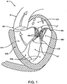
- the left ventricle LV of a normal heart H in systole is illustrated in Fig. 1 .
- the left ventricle LV is contracting and blood flows outwardly through the aortic valve AV, a tricuspid valve in the direction of the arrows.
- Back flow of blood or "regurgitation" through the mitral valve MV is prevented since the mitral valve is configured as a "check valve” which prevents back flow when pressure in the left ventricle is higher than that in the left atrium LA.
- the mitral valve MV comprises a pair of leaflets having free edges FE which meet evenly to close, as illustrated in Fig. 1 .
- the opposite ends of the leaflets LF are attached to the surrounding heart structure along an annular region referred to as the annulus AN.
- the free edges FE of the leaflets LF are secured to the lower portions of the left ventricle LV through chordae tendineae CT (also referred to herein as the chordae) which include a plurality of branching tendons secured over the lower surfaces of each of the valve leaflets LF.
- chordae CT in turn, are attached to the papillary muscles PM which extend upwardly from the lower portions of the left ventricle and interventricular septum IVS.
- a number of structural defects in the heart can cause mitral valve regurgitation.
- Ruptured chordae RCT as shown in Fig. 2 , can cause a valve leaflet LF2 to prolapse since inadequate tension is transmitted to the leaflet via the chordae. While the other leaflet LF 1 maintains a normal profile, the two valve leaflets do not properly meet and leakage from the left ventricle LV into the left atrium LA will occur, as shown by the arrow.
- Regurgitation also occurs in the patients suffering from cardiomyopathy where the heart is dilated and the increased size prevents the valve leaflets LF from meeting properly, as shown in Fig. 3 .
- the enlargement of the heart causes the mitral annulus to become enlarged, making it impossible for the free edges FE to meet during systole.
- the free edges of the anterior and posterior leaflets normally meet along a line of coaptation C as shown in Fig. 3A , but a significant gap G can be left in patients suffering from cardiomyopathy, as shown in Fig. 3B .
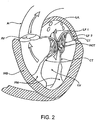
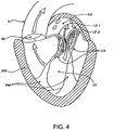
- Mitral valve regurgitation can also occur in patients who have suffered ischemic heart disease where the functioning of the papillary muscles PM is impaired, as illustrated in Fig. 4 .
- the papillary muscles PM do not contract sufficiently to effect proper closure.
- the leaflets LF1 and LF2 then prolapse, as illustrated. Leakage again occurs from the left ventricle LV to the left atrium LA, as shown by the arrow.
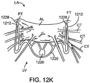
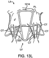
- Fig. 5A more clearly illustrates the anatomy of a mitral valve MV which is a bicuspid valve having an anterior side ANT and a posterior side POST.
- the valve includes an anterior (aortic) leaflet AL and a posterior (mural) leaflet PL.
- Chordae tendineae CT couple the valve leaflets AL, PL with the antero-lateral papillary muscle ALPM and the postero-medial papillary muscle PMPM.
- the valve leaflets AL, PL join one another along a line referred to as the antero-lateral commissure ALC and the posterior-medial commissure PMC.
- the annulus AN circumscribes the valve leaflets, and two regions adjacent an anterior portion of the annulus, on opposite sides of the anterior leaflet are referred to as the left fibrous trigone LFT and also the right fibrous trigone RFT. These areas are indicted generally by the solid triangles.
- Fig. 5B more clearly illustrates the left and right fibrous trigones, LFT, RFT.
- Prosthetic Valve Prosthetic valves have been surgically implanted in the heart as a treatment for mitral regurgitation. Some of these valves have been valves harvested from animals such as porcine valves, and others have been prosthetic mechanical valves with or without a tissue covering. More recently, minimally invasive catheter technology has been used to deliver prosthetic valves to the heart. These valves typically include an anchor for securing the valve to the patient's heart, and a valve mechanism, either a mechanical valve, a valve with animal tissue, or combinations thereof. The prosthetic valve once implanted, takes over for the malfunctioning native valve, thereby reducing or eliminating valvar insufficiency. While some of these valves appear promising, there still is a need for improved valves.
- the following specification discloses exemplary embodiments of a prosthetic valve, a delivery system for the prosthetic valve, and methods of delivering the valve that overcome some of the challenges associated with existing prosthetic valves.
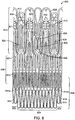
- Fig. 6 illustrates an exemplary embodiment of a prosthetic cardiac valve in the collapsed configuration. Coverings from the frame (e.g. fabric or tissue) have been removed to permit observation of the underlying frame 600. The frame has been unrolled and flattened out.
- the prosthetic valve frame 600 has an atrial region 606, an annular region 608, and a ventricular region 610.
- the frame 600 is formed from a plurality of interconnected struts that form a series of peaks and valleys which can expand and contract relative to one another thereby permitting the frame to be loaded onto a delivery catheter in a collapsed configuration, and then radially expanded at a target treatment site for implantation.
- Preferred embodiments are self-expanding and may be fabricated using superelastic nitinol or other self-expanding materials. Shape memory alloys that spring open above a transition temperature may also be used, and expandable members may also be used to expand the frame when plastic deformation (e.g. balloon expansion) is required to open the frame.
- Atrial region 606 has a skirt 616 which includes a plurality of interconnected struts that form a series of peaks and valleys. In this region, the struts are skewed relative to one another and thus the resulting cell pattern has an enlarged end and the opposite end tapers to a smaller end.
- the anterior portion of the atrial skirt does not have a flanged region like the posterior portion, thus the anterior portion 602 of the atrial region may have shorter struts than the posterior region 604.
- the peaks and valleys in the anterior portion are axially offset from those in the remaining posterior portion of the atrial region.
- the shortened struts and offset peaks and valleys form an alignment element 614 that can assist the physician with visualization of delivery of the prosthetic valve to the mitral valve and also with alignment of the prosthetic valve prior to expansion of the prosthetic valve.
- Optional radiopaque markers 614a are disposed on either side of the offset peaks and valleys and further help with visualization during implantation of the valve.
- the atrial region preferably self-expands to either a cylindrical shape, or it may have a D-shaped cross-section where the anterior portion 602 is substantially flat, and the posterior portion 604 is cylindrically shaped. This allows the atrial skirt to conform to the anatomy of the native mitral valve, thereby preventing obstruction of the left ventricular outflow tract. Additionally, the atrial skirt may also be formed so that upon expansion, the skirt flares outward and forms a flange that can rest against a superior surface of the mitral valve. The flanged region is preferably along the posterior portion of the atrial skirt, and the anterior portion of the atrial skirt remains flangeless. Or, the flange may extend entirely around the atrial skirt.
- the atrial region is connected to the adjacent annular region 608 with connecting struts which are preferably linear and substantially parallel to the longitudinal axis of the frame.
- the annular region 608 is also comprised of a plurality of axially oriented and interconnected struts that form peaks and valleys that allow radial expansion.
- the struts are preferably parallel with one another and parallel with the longitudinal axis of the frame.
- the annular region may also be self-expanding and expand into a cylindrical shape, or more preferably the annular region may expand to have a D-shaped cross-section as described above with respect to the atrial region.
- the annular region may similarly have a flat anterior portion, and a cylindrically shaped posterior portion.
- Connector struts join the annular region with the ventricular region 610.
- the ventricular region 610 also includes a plurality of interconnected struts that form peaks and valleys. Additionally, the struts in the ventricular region form the leaflet commissures 613 which are covered with fabric, pericardial tissue, or other materials to form the prosthetic valve leaflets. Holes in the commissures allow suture to be attached thereto. Struts in the ventricular region also form a ventricular skirt 628 which expands outward to engage the anterior and posterior mitral valve leaflets, and struts in the ventricular region also form the anterior tabs 624 and the posterior tab 630. The anterior tabs are designed to capture the anterior mitral valve leaflet between an inner surface of the anterior tab and outer surface of the ventricular skirt.
- any adjacent chordae tendineae may also be captured therebetween.
- the tip of the anterior tab engages the fibrous trigone on an anterior portion of the mitral valve, one on the left and one on the right side.
- the posterior tab similarly captures the posterior mitral valve leaflet between an inner surface of the posterior tab and an outer surface of the ventricular skirt, along with any adjacent chordae tendineae. This will be described in more detail below.
- strut length or axial position of the anterior or posterior tabs along the frame deployment of the tabs may be controlled.
- the length of the struts in the anterior tabs and posterior tabs 624, 630 as well as their relative position along the frame are the same as one another, when a constraining sheath is retracted away from the tabs, the anterior and posterior tabs will partially spring outward together. As the constraining sheath is further retracted, the remainder of the anterior tabs will self-expand radially outward. Further retraction of the constraining sheath then allows the remainder of the posterior tab to finish its radial expansion, and finally the ventricular skirt will radially expand outward.
- Suture holes 621 are disposed along the struts of the annular region as well as the ventricular region to allow attachment of a cover such as pericardium or a polymer such as Dacron or ePTFE, or another biocompatible material.
- the suture holes may also be disposed along any other part of the frame.
- Barbs 623 are disposed along the ventricular skirt 628 to help anchor the prosthetic valve to adjacent tissue.
- Commissure tabs or tabs 612 are disposed on the tips of the commissures 613 and may be used to releasably couple the commissures with a delivery system as will be described below. This allows the frame to expand first, and then the commissures may be released from the delivery system afterwards.
- strut geometries may be used, and additionally that strut dimensions such as length, width, thickness, etc. may be adjusted in order to provide the prosthesis with the desired mechanical properties such as stiffness, radial crush strength, commissure deflection, etc. Therefore, the illustrated geometry is not intended to be limiting.
- the frame may be formed by electrical discharge machining (EDM), laser cutting, photochemical etching, or other techniques known in the art. Hypodermic tubing or flat sheets may be used to form the frame.
- EDM electrical discharge machining
- Hypodermic tubing or flat sheets may be used to form the frame.
- the prosthetic valve may be loaded onto a delivery catheter in a collapsed configuration and constrained in the collapsed configuration with a constraining sheath. Removal of the constraining sheath will allow the prosthesis to self-expand into its unbiased pre-set shape.
- an expandable member such as a balloon may be used to radially expand the prosthesis into its preferred expanded configuration by plastic deformation.
- Fig. 7 illustrates another exemplary embodiment of a prosthetic cardiac valve in the collapsed configuration, and similar to the previous embodiment with the major difference being the strut lengths in the anterior tabs, posterior tab, and ventricular skirt. Varying the strut lengths allow the sequence of expansion of the anterior and posterior tabs and ventricular skirt to be controlled. Coverings from the frame (e.g. fabric or tissue) has been removed to permit observation of the underlying frame 700. The frame has been unrolled and flattened out.
- the prosthetic valve frame 700 has an atrial region 706, an annular region 708, and a ventricular region 710.
- the frame 700 is formed from a plurality of interconnected struts that form a series of peaks and valleys which can expand and contract relative to one another thereby permitting the frame to be loaded onto a delivery catheter in a collapsed configuration, and then radially expanded at a target treatment site for implantation.
- Preferred embodiments are self-expanding and may be fabricated using superelastic nitinol or other self-expanding materials. Shape memory alloys that spring open above a transition temperature may also be used, and expandable members may also be used to expand the frame when plastic deformation (e.g. balloon expansion) is required to open the frame.
- Atrial region 706 has a skirt 716 which includes a plurality of interconnected struts that form a series of peaks and valleys. In this region, the struts are skewed relative to one another and thus the resulting cell pattern has an enlarged end and the opposite end tapers to a smaller end.
- An anterior portion 702 of the atrial region has shorter struts than the posterior region 704. Thus the peaks and valleys in the anterior portion are axially offset from those in the remaining posterior portion of the atrial region. This allows creation of an alignment element 714 to help the physician deliver the prosthetic valve to the mitral valve and align the prosthetic valve prior to expansion of the prosthetic valve.
- Other aspects of the atrial region 706 are similar to those of the atrial region 606 in Fig.
- Optional radiopaque markers 714a are disposed on either side of the offset peaks and valleys and help with visualization during implantation of the valve.
- the atrial region preferably self-expands to either a cylindrical shape, or it may have a D-shaped cross-section where the anterior portion 702 is substantially flat, and the posterior portion 704 is cylindrically shaped. This allows the atrial skirt to conform to the anatomy of the native mitral valve, thereby preventing obstruction of the left ventricular outflow tract. Additionally, the atrial skirt may also be formed so that upon expansion, the skirt flares outward and forms a flange that can rest against a superior surface of the mitral valve.
- the flanged region is preferably along the posterior portion of the atrial skirt, and the anterior portion of the atrial skirt remains flangeless. Or, the flange may extend entirely around the atrial skirt.
- the atrial region is connected to the adjacent annular region 708 with connecting struts which are preferably linear and substantially parallel to the longitudinal axis of the frame.
- the annular region 708 is also comprised of a plurality of axially oriented and interconnected struts that form peaks and valleys that allow radial expansion.
- the struts are preferably parallel with one another and parallel with the longitudinal axis of the frame.
- the annular region may also be self-expanding and expand into a cylindrical shape, or more preferably the annular region may expand to have a D-shaped cross-section as described above with respect to the atrial region.
- the annular region may similarly have a flat anterior portion, and a cylindrically shaped posterior portion.
- Connector struts join the annular region with the ventricular region 710.
- the ventricular region 710 also includes a plurality of interconnected struts that form peaks and valleys. Additionally, the struts in the ventricular region form the leaflet commissures 713 which are covered with fabric, pericardial tissue, or other materials to form the prosthetic valve leaflets. Holes in the commissures allow suture to be attached thereto. Struts in the ventricular region also form a ventricular skirt 728 which expands outward to engage the anterior and posterior mitral valve leaflets, and struts in the ventricular region also form the anterior tabs 724 and the posterior tab 730. The anterior tabs are designed to capture the anterior mitral valve leaflet between an inner surface of the anterior tab and outer surface of the ventricular skirt.
- any adjacent chordae tendineae may also be captured therebetween.
- the tip of the anterior tab engages the fibrous trigone on an anterior portion of the mitral valve, one on the left and one on the right side.
- the posterior tab similar captures the posterior mitral valve leaflet between an inner surface of the posterior tab and an outer surface of the ventricular skirt, along with any adjacent chordae tendineae. This will be described in more detail below.
- strut length or axial position of the anterior or posterior tabs along the frame deployment of the tabs may be controlled.
- the length of the struts in the anterior tabs and posterior tabs 724, 730 as well as their relative position along the frame are the same as one another, when a constraining sheath is retracted away from the tabs, the anterior and posterior tabs will partially spring outward together. As the constraining sheath is further retracted, the remainder of the anterior tabs will self-expand radially outward because they are the shortest relative to the struts in the ventricular skirt and the posterior tab.
- Suture holes 721 are disposed along the struts of the annular region as well as the ventricular region to allow attachment of a cover such as pericardium or a polymer such as Dacron or ePTFE.
- the suture holes may also be disposed along any other part of the frame.
- Barbs 723 are disposed along the ventricular skirt 728 to help anchor the prosthetic valve to adjacent tissue.
- Commissure tabs or tabs 712 are disposed on the tips of the commissures 713 and may be used to releasably couple the commissures with a delivery system as will be described below. This allows the frame to expand first, and then the commissures may be released from the delivery system afterwards.
- strut geometries may be used, and additionally that strut dimensions such as length, width, thickness, etc. may be adjusted in order to provide the prosthesis with the desired mechanical properties such as stiffness, radial crush strength, commissure deflection, etc. Therefore, the illustrated geometry is not intended to be limiting.
- the frame may be formed similarly as described above with respect to Fig. 6 .
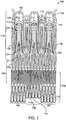
- Fig. 8 illustrates another exemplary embodiment of a prosthetic cardiac valve in the collapsed configuration, and is similar to the previous embodiments, with the major difference being that the posterior tab is designed to expand to form an elongate horizontal section which allows engagement and anchoring of the posterior tab with the sub-annular region between the posterior leaflet and the ventricular wall.
- the elongate horizontal section contacts a larger region of the sub-annular region as compared with a posterior tab that only has a tapered tip formed from a single hinge between struts.
- This provides enhanced anchoring of the prosthetic valve.
- the anterior tabs will completely self-expand first, followed by the posterior tab and then the ventricular skirt. However, in some situations external factors such as the delivery system, anatomy, etc.
- the frame 800 may alter the sequence of expansion, and therefore this is not intended to be limiting. Coverings from the frame (e.g. fabric or tissue) have been removed to permit observation of the underlying frame 800. The frame has been unrolled and flattened out.
- the prosthetic valve frame 800 has an atrial region 806, an annular region 808, and a ventricular region 810.
- the frame 800 is formed from a plurality of interconnected struts that form a series of peaks and valleys which can expand and contract relative to one another thereby permitting the frame to be loaded onto a delivery catheter in a collapsed configuration, and then radially expanded at a target treatment site for implantation.
- Preferred embodiments are self-expanding and may be fabricated using superelastic nitinol or other self-expanding materials. Shape memory alloys that spring open above a transition temperature may also be used, and expandable members may also be used to expand the frame when plastic deformation (e.g. balloon expansion) is required to open the frame.
- Atrial region 806 has a skirt 816 which includes a plurality of interconnected struts that form a series of peaks and valleys. In this region, the struts are skewed relative to one another and thus the resulting cell pattern has an enlarged end and the opposite end tapers to a smaller end.
- An anterior portion 802 of the atrial region has shorter struts than the posterior region 804. Thus the peaks and valleys in the anterior portion are axially offset from those in the remaining posterior portion of the atrial region. This allows creation of an alignment element 814 to help the physician deliver the prosthetic valve to the mitral valve and align the prosthetic valve prior to expansion of the prosthetic valve.
- Other aspects of the atrial region 806 are similar to those of the atrial region 606 in Fig.
- the flanged region is preferably along the posterior portion of the atrial skirt, and the anterior portion of the atrial skirt remains flangeless. Or, the flange may extend entirely around the atrial skirt.
- the atrial region is connected to the adjacent annular region 808 with connecting struts which are preferably linear and substantially parallel to the longitudinal axis of the frame.
- the annular region 808 is also comprised of a plurality of axially oriented and interconnected struts that form peaks and valleys that allow radial expansion.
- the struts are preferably parallel with one another and parallel with the longitudinal axis of the frame.
- the annular region may also be self-expanding and expand into a cylindrical shape, or more preferably the annular region may expand to have a D-shaped cross-section as described above with respect to the atrial region.
- the annular region may similarly have a flat anterior portion, and a cylindrically shaped posterior portion.
- Connector struts join the annular region with the ventricular region 810.
- the ventricular region 810 also includes a plurality of interconnected struts that form peaks and valleys. Additionally, the struts in the ventricular region form the leaflet commissures 813 which are covered with fabric, pericardial tissue, or other materials to form the prosthetic valve leaflets. Holes in the commissures allow suture to be attached thereto. Struts in the ventricular region also form a ventricular skirt 828 which expands outward to engage the anterior and posterior mitral valve leaflets, and struts in the ventricular region also form the anterior tabs 824 and the posterior tab 830. The anterior tabs are designed to capture the anterior mitral valve leaflet between an inner surface of the anterior tab and outer surface of the ventricular skirt.
- the tip of the anterior tab engages the fibrous trigone on an anterior portion of the mitral valve, one on the left and one on the right side.
- the posterior tab similarly captures the posterior mitral valve leaflet between an inner surface of the posterior tab and an outer surface of the ventricular skirt, along with any adjacent chordae tendineae. This will be described in more detail below.
- the posterior tab is similar to the posterior tabs described above in Figs. 6-7 , except that in this embodiment, the posterior tab comprises four interconnected struts as opposed to two interconnected struts. Thus, in this embodiment the plurality of interconnected struts form three hinged regions 836 along the tab.
- the hinged regions Upon expansion of the posterior tab, the hinged regions will also expand, thereby forming an elongate horizontal section which allows engagement and anchoring of the posterior tab with the sub-annular region between the posterior leaflet and the ventricular wall. This may help position and anchor the prosthetic valve better than posterior tabs which only have a smaller footprint or a single tapered tip for engagement with the posterior portion of the mitral valve.
- the posterior tab in this embodiment may be substituted with any of the other posterior tabs described in this specification.
- strut length or axial position of the anterior or posterior tabs along the frame deployment of the tabs may be controlled.
- the length of the struts in the anterior tabs and posterior tabs 824, 830 as well as their relative position along the frame are the same as one another, when a constraining sheath is retracted away from the tabs, the anterior and posterior tabs will partially spring outward together. As the constraining sheath is further retracted, the remainder of the anterior tabs will self-expand radially outward because they are the shortest relative to the struts in the ventricular skirt and the posterior tab.
- Suture holes 821 are disposed along the struts of the annular region as well as the ventricular region to allow attachment of a cover such as pericardium or a polymer such as Dacron or ePTFE.
- the suture holes may also be disposed along any other part of the frame.
- Barbs 823 are disposed along the ventricular skirt 828 to help anchor the prosthetic valve to adjacent tissue.
- Commissure tabs or tabs 812 are disposed on the tips of the commissures 813 and may be used to releasably couple the commissures with a delivery system as will be described below. This allows the frame to expand first, and then the commissures may be released from the delivery system afterwards.
- strut geometries may be used, and additionally strut dimensions such as length, width, thickness, etc. may be adjusted in order to provide the prosthesis with the desired mechanical properties such as stiffness, radial crush strength, commissure deflection, etc. Therefore, the illustrated geometry is not intended to be limiting.
- the frame may be formed similarly as described above.
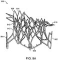
- Fig. 9A illustrates the frame 900 of a prosthetic cardiac valve after it has expanded. Any of the frame embodiments described above may take this form as each of the above frames have similar geometry but they expand in different order.
- the frame includes the atrial skirt 906 with anterior portion 914 and posterior portion 916. A flanged region is formed around the posterior portion and the anterior portion remains flangeless. Additionally, the anterior portion is generally flat, while the posterior portion is cylindrically shaped, thereby forming a D-shaped cross-section which accommodates the mitral valve anatomy.
- Fig. 9B is a top view of the embodiment in Fig. 9A and more clearly illustrates the D-shaped cross-section.
- the frame also includes the annular region 910 and ventricular skirt 912.
- Anterior tabs 904 (only one visible in this view) is fully expanded such that a space exists between the inner surface of the anterior tab and an outer surface of the ventricular skirt. This allows the anterior leaflet and adjacent chordae to be captured therebetween.
- the posterior tab 902 is also fully deployed, with a similar space between the inner surface of the posterior tab 902 and an outer surface of the ventricular skirt. This allows the posterior leaflet and adjacent chordae tendineae to be captured therebetween.
- the commissure posts 908 are also visible and are disposed in the inner channel formed by the frame. The commissure posts are used to form the prosthetic mitral valve leaflets.
- the overall shape of the expanded frame is D-shaped, with the anterior portion flat and the posterior portion cylindrically shaped.
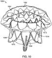
- Fig. 10 illustrates the expanded frame covered with a cover 1002 such as pericardial tissue or a polymer such as ePTFE or a fabric like Dacron attached to the frame, thereby forming the prosthetic cardiac valve 1000.
- the atrial skirt may be entirely covered by a material, or in preferred embodiments, the covering is only disposed between adjacent struts 1012 in adjacent cells in the flanged portion of the atrial skirt.
- the area 1014 between adjacent struts within the same cell remain uncovered. This allows blood flow to remain substantially uninterrupted while the prosthetic valve is being implanted.
- Suture 1010 may be used to attach the cover to the frame. In this view, only the posterior tab 1006 is visible on the posterior portion of the prosthetic valve along with ventricular skirt 1008 and atrial skirt 1004.
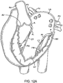
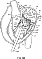
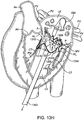
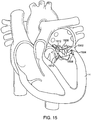
- Fig. 15 illustrates an example of this where the prosthetic valve 1506 which may be any of the embodiments having both anterior and posterior tabs described herein, is successfully anchored to the mitral valve 1502 of a patient's heart H.
- the posterior tab 1508 has successfully engaged the posterior leaflet 1504, and the anterior tab 1510 has successfully engaged the anterior leaflet 1512.
- Proper anterior and posterior anchoring secures the inferior portion of the prosthetic valve and prevents unwanted rotation or pivoting of the prosthetic valve, as well as preventing unwanted axial movement upstream or downstream.
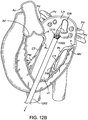
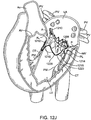
- the posterior tab may not anchor the prosthetic device to the posterior leaflet of native valve. For example, if the physician improperly delivers and deploys the prosthetic valve it may not properly engage the posterior leaflet. Or, in some situations, the posterior leaflet may have an irregular shape or may be fragile and therefore not be strong enough for anchoring with the posterior tab.
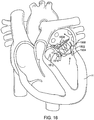
- Fig. 16 which illustrates the prosthetic valve 1506 rotating due to the retrograde blood pressure from the left ventricle of the heart H and exerted on the prosthesis during systole.
- the posterior portion of the prosthesis pivots upward into the left atrium creating a leak around the prosthesis as indicated by the arrows.
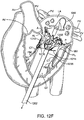
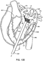
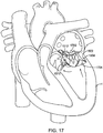
- Fig. 17 illustrates an alternative embodiment of prosthetic valve that helps prevent posterior pivoting.
- the prosthetic valve 1702 in this embodiment is a prosthetic mitral valve and it is implanted in a native mitral valve 1502 of a patient's heart H.
- the prosthetic valve 1702 generally takes the same form as other prosthetic valves described in this specification, with the major exception that it does not have posterior tabs.
- the prosthetic valve includes a foot 1704 which prevents pivoting.
- the foot is an enlarged portion of the prosthetic valve that extends radially outward from the body of the prosthesis sufficiently far so that the cross-sectional area of the ventricular portion of the prosthetic valve is large enough to prevent it from pivoting or rotating up into the atrium.
- the foot may be any number of structures which prevent pivoting of the prosthesis.
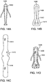
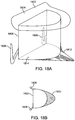
- Figs. 18A-18B illustrate a schematic of a prosthetic valve having an anti-pivoting mechanism.
- Fig. 18A illustrates the prosthetic valve 1802 which is generally the same as any of the other valve embodiments described herein with the major difference being that it does not have a posterior tab.
- the prosthetic valve 1802 may have any of the features described in any other embodiments disclosed herein.
- the prosthetic valve may include an atrial flange 1804, an annular region 1808 and a ventricular region or ventricular skirt 1814.
- the valve preferably also includes two anterior tabs 1806 for engaging the anterior leaflet and the trigones.
- the valve has a foot 1812 which is a wedge shaped region of the prosthesis that extends radially outward.
- Fig. 18B illustrates a top view of the prosthetic valve 1802 seen in Fig. 18A .
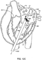
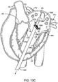
- Fig. 18C illustrates a perspective view of a prosthetic valve 1802 that generally takes the same form as other valve embodiments described herein with the major difference being that instead of having a posterior tab for anchoring to a valve leaflet, the valve has a foot 1812 which anchors the posterior part of the valve to the posterior portion of the native valve.
- the valve includes an atrial flange 1804, anterior trigonal tabs 1806, an annular region 1808, and a ventricular skirt region 1818 that generally take the same form as described in other embodiments.
- the foot 1812 may be any structure which extends radially outward and prevents the prosthetic valve from rotating or pivoting. In some embodiments, the foot may extend radially outward 10 mm or more.
- the foot includes a central element 1812 which has been formed from two struts 1814 that are coupled together with a connector to form a V or U-shaped structure that extends radially outward.
- a cover 1816 such as pericardial tissue, or any of the other cover materials discussed herein is attached to the central element 1812 and to adjacent struts on either side, thereby forming a vestibule similar to that seen on a camping tent, or a cattle pusher on a locomotive engine (sometimes referred to as a pilot).
- This structure has a larger cross-section than the native valve, and thus it prevents the prosthetic valve from rotating through the valve into the atrium (in the case of a mitral valve prosthesis).
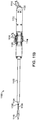
- Fig. 19 illustrates a flat pattern used to cut the prosthetic valve from tubing or a flat sheet which is then rolled and welded into a cylinder. Electrical discharge machining (EDM), laser cutting, or photochemical etching are techniques that may be used to cut the flat pattern.
- the prosthesis 1902 generally takes the same form as other prosthetic valves disclosed herein, and thus not every feature will be described in detail.
- the prosthesis 1902 includes an atrial region 1910 having an atrial skirt, an annular region 1912 and a ventricular region 1914.
- the ventricular region includes anterior tabs 1904 with tips 1908 that engage the fibrous trigones on either side of the anterior leaflet of a mitral valve.
- the anti-pivoting mechanism is formed from an elongate pair of struts 1906 which extend axially further than the struts of the ventricular region.
- the struts 1906 may be formed to flare radially outward upon self-expansion and they may be covered with tissue or synthetic material to form the enlarged area of the foot which prevents pivoting.
- Other aspects of the prosthetic valve such as the atrial flange, the annular region, the ventricular skirt, suture holes, commissure posts, commissure tabs, alignment element, flat anterior shape, cylindrical posterior shape, D-shaped cross-section may generally take the same form as described in other embodiments of this specification.
- the prosthetic valve is preferably formed from shape memory or superelastic nitinol, or it may be made from other self-expanding materials known in the art.
- the valve may also be balloon expandable and be made from materials such as stainless steel, cobalt-chromium, or other materials known in the art.
- the foot may take any number of shapes and may be a combination of metal or fabric and/or polymer features integral with or coupled to the prosthetic valve.
- the anchoring elements on the prosthetic valve may be deployed in any desired order.
- the atrial skirt deploys first and anchors the valve to the atrial floor followed by deployment of the annular region into the annulus, then the anterior tabs capture the valve leaflets, followed by the foot, and then the ventricular skirt, and then the commissures.
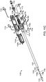
- Figs. 20A-20B illustrate another exemplary embodiment of a prosthetic valve combining features of several previously disclosed embodiments such as the foot and a posterior tab.
- Fig. 20A illustrates a rear view looking head on at a prosthetic valve 2002 which may take the form of any of the embodiments disclosed herein.
- the upper end of the prosthesis includes an atrial flange 2004 which helps anchor the device to the floor of the atrium as previously described.
- the prosthesis also includes a pair of anterior trigonal tabs for anchoring the prosthesis to the fibrous trigones of the anterior portion of the valve annulus.
- the posterior portion of the prosthesis includes a foot 2008 like the foot previously described above, and a posterior tab 2010 which may take the form of any of the previous embodiments.
- Fig. 20B illustrates another side view of the prosthesis 2020, this time rotated about its longitudinal axis to more clearly illustrate one anterior tab (the other is obstructed), as well as the foot and the posterior tab.
- alternative embodiments may also have barbs, texturing or other surface features on the foot, the posterior tab, or adjacent thereto in order to help further anchor the prosthesis into the tissue.
- Fig. 21 illustrates an exemplary embodiment of a prosthesis 2102 having a foot 2110, posterior tab 2106, anterior tab 2106 and barbs 2112.
- the barbs may be pointed protrusions, or they may be textured regions. They may be disposed on the foot, on the posterior tab, or on both portions of the device.
- Other aspects of the prosthesis such as the atrial flange 2104, anterior tab 2106, as well as other features including the annular skirt, ventricular skirt, commissures, etc. may take the form of any embodiment described herein.
- Figs. 11A-11D illustrate an exemplary embodiment of a delivery system that may be used to deliver any of the prosthetic valves disclosed in this specification. While the delivery system is designed to preferably deliver the prosthetic valve transapically, one of skill in the art will appreciate that it may also be modified so that the prosthetic valve may be delivered via a catheter transluminally, such using a transseptal route. One of skill in the art will appreciate that using a transseptal route may require the relative motion of the various shafts to be modified in order to accommodate the position of the delivery system relative to the mitral valve.
- Fig. 11A illustrates a perspective view of delivery system 1100.
- the delivery system 1100 includes a handle 1112 near a proximal end of the delivery system and a distal tissue penetrating tip 1110.
- Four elongate shafts are included in the delivery system and include an outer sheath catheter shaft 1102, a bell catheter shaft 1104 which is slidably disposed in the outer sheath catheter shaft 1102, a hub catheter shaft 1106 which remains stationary relative to the other shafts, but the bell catheter shaft slides relative to the hub shaft, and finally an inner guidewire catheter shaft 1108 which is also fixed relative to the other shafts and has a lumen sized to receive a guidewire which passes therethrough and exits the distal tissue penetrating tip.
- An actuator mechanism 1114 is used to control movement of the various shafts as will be explained in greater detail below, and flush lines 1116, 1118 with luer connectors are used to flush the annular regions between adjacent shafts.
- Flush line 1118 is used to flush the annular space between the outer sheath catheter shaft 1102 and the bell catheter shaft 1104.
- Flush line 1116 is used to flush the annular space between the bell catheter 1104 and the hub catheter 1106.
- the inner guidewire catheter shaft 1108 is stationary relative to the hub catheter 1106 therefore the annular space may be sealed with an o-ring or other material.
- Luer connector 1122 allows flushing of the guidewire lumen and a hemostatic valve such as a Tuohy-Borst may be coupled to the luer connector to allow a guidewire to be advanced through the guidewire catheter shaft while maintaining hemostasis. Screws 1120 keep the handle housing coupled together.
- Fig. 11B illustrates a side view of the delivery system 1100.
- Fig. 11C is a partial exploded view of the delivery system 1100 and more clearly illustrates the components in the handle 1112 and how they interact.
- the handle 1112 includes a housing having two halves 1112a, 1112b which hold all the components.
- the handle is preferably held together with screws 1120 and nuts 1120b, although it may also be sealed using other techniques such as a press fit, snap fit, adhesive bonding, ultrasonic welding, etc.
- Rotation of actuator wheel 1114 is translated into linear motion of threaded insert 1124.
- the outer sheath catheter shaft 1102 is coupled to the threaded insert 1124, therefore rotation of actuator wheel 1114 in one direction will advance the sheath catheter shaft 1102, and rotation in the opposite direction will retract the sheath catheter shaft 1102.
- actuator wheel 1114 retracts threaded insert 1124 enough to bump into pins 1126 which are coupled to insert 1128, thereby also moving insert 1128.
- the bell catheter shaft 1106 is coupled to insert 1128, therefore further rotation of the actuator wheel 1114 will move the outer shaft 1102 and also move the bell catheter shaft 1106.
- Rotation of the actuator wheel in the opposite direction advances the sheath and threaded insert 1124 disengages from pins 1126.
- Spring 1130 returns insert 1128 to its unbiased position, thereby returning the bell catheter shaft to its unbiased position.
- any of the prosthetic cardiac valves disclosed herein may be carried by delivery system 1100.
- the atrial skirt, annular skirt, anterior tabs, posterior tab and ventricular skirt are loaded over the bell catheter shaft and disposed under the outer sheath catheter shaft 1102.
- the ventricular skirt is loaded proximally so that it is closest to the handle 1112 and the atrial skirt is loaded most distally so it is closest to the tip 1110. Therefore, retraction of outer sheath catheter shaft 1102 plays a significant part in controlling deployment of the prosthetic cardiac valve.
- the atrial skirt therefore expands first when the outer sheath catheter is retracted.
- the prosthetic valve commissures may be coupled with a hub 1106a on the distal portion of hub catheter 1106 and then the bell catheter shaft is disposed thereover, thereby releasably engaging the commissures with the delivery catheter. Once other portions of the prosthetic cardiac valve have expanded, the commissures may be released.
- Fig. 11D highlights the distal portion of the delivery system 1100.
- Outer sheath catheter shaft 1102 advances and retracts relative to bell catheter shaft 1104 which is slidably disposed in the outer sheath catheter shaft 1102.
- Hub catheter shaft 1106 is shown slidably disposed in bell catheter shaft 1104 and with bell catheter shaft 1104 retracted so as to expose the hub 1106a having slots 1106b that hold the prosthetic valve commissures.
- Inner guidewire catheter shaft 1108 is the innermost shaft and has a tapered conical section 1130 which provides a smooth transition for the prosthetic valve and prevents unwanted bending or buckling of the prosthetic cardiac valve frame.
- Tissue penetrating tip 1110 is adapted to penetrate tissue, especially in a cardiac transapical procedure.
- a number of methods may be used to deliver a prosthetic cardiac valve to the heart.
- Exemplary methods of delivering a prosthetic mitral valve may include a transluminal delivery route which may also be a transseptal technique which crosses the septum between the right and left sides of the heart, or in more preferred embodiments, a transapical route may be used such as illustrated in Figs. 12A-12L .
- the delivery device previously described above may be used to deliver any of the embodiments of prosthetic valves described herein, or other delivery devices and other prosthetic valves may also be used, such as those disclosed in US Patent Application No. 13/096,572 , previously incorporated herein by reference.
- the prosthetic cardiac valve of Fig. 6 is used so that the anterior tabs deploy first, followed by the posterior tab, and then the ventricular skirt.
- deployment is generally the same, but the foot is expanded instead of the posterior tab.
- Fig. 12A illustrates the basic anatomy of the left side of a patient's heart including the left atrium LA and left ventricle LV.
- Pulmonary veins PV return blood from the lungs to the left atrium and the blood is then pumped from the left atrium into the left ventricle across the mitral valve MV.
- the mitral valve includes an anterior leaflet AL on an anterior side A of the valve and a posterior leaflet PL on a posterior side P of the valve.
- the leaflets are attached to chordae tendineae CT which are subsequently secured to the heart walls with papillary muscles PM.
- the blood is then pumped out of the left ventricle into the aorta Ao with the aortic valve AV preventing regurgitation.
- Fig. 12B illustrates transapical delivery of a delivery system 1202 through the apex of the heart into the left atrium LA via the left ventricle LV.
- the delivery system 1202 may be advanced over a guidewire GW into the left atrium, and a tissue penetrating tip 1204 helps the delivery system pass through the apex of the heart by dilating the tissue and forming a larger channel for the remainder of the delivery system to pass through.
- the delivery catheter carries prosthetic cardiac valve 1208. Once the distal portion of the delivery system has been advanced into the left atrium, the outer sheath 1206 may be retracted proximally (e.g. toward the operator) thereby removing the constraint from the atrial portion of the prosthetic valve 1208.
- the annular region of the prosthetic cardiac valve self-expands next into engagement with the valve annulus.
- the annular region also preferably has the D-shaped geometry, although it may also be cylindrical or have other geometries to match the native anatomy.
- retraction of sheath 1206 eventually allows both the anterior 1212 and posterior 1214 tabs to partially self-expand outward preferably without engaging the anterior or posterior leaflets or the chordae tendineae.
- both the anterior tabs 1212 (only one visible in this view) to complete their self-expansion so that the anterior leaflet is captured between an inner surface of each of the anterior tabs and an outer surface of the ventricular skirt 1216, as illustrated in Fig. 12F .
- the posterior tab 1214 remains partially open, but has not completed its expansion yet. Additionally, the tips of the anterior tabs also anchor into the left and right fibrous trigones of the mitral valve, as will be illustrated in greater detail below.
- Fig. 12G further retraction of the outer sheath 1206 then releases the constraints from the posterior tab 1214 allowing it to complete its self-expansion, thereby capturing the posterior leaflet PL between an inner surface of the posterior tab 1214 and an outer surface of the ventricular skirt 1218.
- Fig. 12H the sheath is retracted further releasing the ventricular skirt 1220 and allowing the ventricular skirt 1220 to radially expand outward, further capturing the anterior and posterior leaflets between the outer surface of the ventricular skirt and their respective anterior or posterior tabs. Expansion of the ventricular skirt also pushes the anterior and posterior leaflets outward, thereby ensuring that the native leaflets do not interfere with any portion of the prosthetic valve or the prosthetic valve leaflets.
- the prosthetic valve is now anchored in position above the mitral valve, along the annulus, to the valve leaflets, and below the mitral valve, thereby securing it in position.
- actuation of the delivery device now retracts the outer sheath 1206 and the bell catheter shaft 1222 so as to remove the constraint from the hub catheter 1224, as illustrated in Fig. 12I .
- the delivery system 1202 and guidewire GW are then removed, leaving the prosthetic valve 1208 in position where it takes over for the native mitral valve, as seen in Fig. 12J .
- Figs. 12K and 12L highlight engagement of the anterior and posterior tabs with the respective anterior and posterior leaflets.
- anterior tabs 1212 after anterior tabs 1212 have been fully expanded, they capture the anterior leaflet AL and may capture adjacent chordae tendineae between an inside surface of the anterior tab and an outer surface of the ventricular skirt 1220.
- the tips 1228 of the anterior tabs 1212 are engaged with the fibrous trigones FT of the anterior side of the mitral valve.
- the fibrous trigones are fibrous regions of the valve thus the anterior tabs further anchor the prosthetic valve into the native mitral valve anatomy.
- One anterior tab anchors into the left fibrous trigone, and the other anterior tabs anchors into the right fibrous trigone.
- Fig. 12L illustrates engagement of the posterior tab 1214 with the posterior leaflet PL which is captured between an inner surface of the posterior tab and an outer surface of the ventricular skirt 1220. Additionally, adjacent chordae tendineae may be captured between the posterior tab and ventricular skirt.
- Figs. 13A-13L illustrate another exemplary embodiment of a delivery method. This embodiment is similar to that previously described, with the major difference being the order in which the prosthetic cardiac valve self-expands into engagement with the mitral valve. Any delivery device or any prosthetic valve disclosed herein may be used, however in preferred embodiments, the embodiment of Fig. 7 is used. Varying the order may allow better positioning of the implant, easier capturing of the valve leaflets, and better anchoring of the implant. This exemplary method also preferably uses a transapical route, although transseptal may also be used.
- Fig. 13A illustrates the basic anatomy of the left side of a patient's heart including the left atrium LA and left ventricle LV.
- Pulmonary veins PV return blood from the lungs to the left atrium and the blood is then pumped from the left atrium into the left ventricle across the mitral valve MV.
- the mitral valve includes an anterior leaflet AL on an anterior side A of the valve and a posterior leaflet PL on a posterior side P of the valve.
- the leaflets are attached to chordae tendineae CT which are subsequently secured to the heart walls with papillary muscles PM.
- the blood is then pumped out of the left ventricle into the aorta AO with the aortic valve AV preventing regurgitation.
- Fig. 13B illustrates transapical delivery of a delivery system 1302 through the apex of the heart into the left atrium LA via the left ventricle LV.
- the delivery system 1302 may be advanced over a guidewire GW into the left atrium, and a tissue penetrating tip 1304 helps the delivery system pass through the apex of the heart by dilating the tissue and forming a larger channel for the remainder of the delivery system to pass through.
- the delivery catheter carries prosthetic cardiac valve 1308. Once the distal portion of the delivery system has been advanced into the left atrium, the outer sheath 1306 may be retracted proximally (e.g. toward the operator) thereby removing the constraint from the atrial portion of the prosthetic valve 1308.
- the atrial skirt 1310 may self-expand radially outward.
- the atrial skirt may have a cylindrical shape or it may be D-shaped as discussed above with a flat anterior portion and a cylindrical posterior portion so as to avoid interfering with the aortic valve and other aspects of the left ventricular outflow tract.
- the prosthesis may be oriented and properly positioned by rotating the prosthesis and visualizing the alignment element previously described.
- the prosthetic cardiac valve may be advanced upstream or downstream to properly position the atrial skirt.
- the atrial skirt forms a flange that rests against a superior surface of the mitral valve and this anchors the prosthetic valve and prevents it from unwanted movement downstream into the left ventricle.
- the annular region of the prosthetic cardiac valve self-expands next into engagement with the valve annulus.
- the annular region also preferably has the D-shaped geometry, although it may also be cylindrical or have other geometries to match the native anatomy.
- retraction of sheath 1306 eventually allows both the anterior 1312 and posterior 1314 tabs to partially self-expand outward preferably without engaging the anterior or posterior leaflets or the chordae tendineae.
- both the anterior tabs 1312 (only one visible in this view) to complete their self-expansion so that the anterior leaflet is captured between an inner surface of each of the anterior tabs and an outer surface of the ventricular skirt 1316, as illustrated in Fig. 13F .
- the posterior tab 1214 remains partially open, but has not completed its expansion yet. Additionally, the tips of the anterior tabs also anchor into the left and right fibrous trigones of the mitral valve, as will be illustrated in greater detail below.
- Fig. 13G further retraction of the outer sheath 1306 then releases the constraint from the ventricular skirt 1320 allowing the ventricular skirt to radially expand. This then further captures the anterior leaflets AL between the anterior tab 1312 and the ventricular skirt 1316. Expansion of the ventricular skirt also pushes the anterior and posterior leaflets outward, thereby ensuring that the native leaflets do not interfere with any portion of the prosthetic valve or the prosthetic valve leaflets. Further retraction of sheath 1306 as illustrated in Fig. 13H releases the constraint from the posterior tab 1314 allowing it to complete its self-expansion, thereby capturing the posterior leaflet PL between an inner surface of the posterior tab 1314 and an outer surface of the ventricular skirt 1318. The prosthetic valve is now anchored in position above the mitral valve, along the annulus, to the valve leaflets, and below the mitral valve, thereby securing it in position.
- actuation of the delivery device now retracts the outer sheath 1306 and the bell catheter shaft 1322 so as to remove the constraint from the hub catheter 1324, as illustrated in Fig. 13I .
- the delivery system 1302 and guidewire GW are then removed, leaving the prosthetic valve 1308 in position where it takes over for the native mitral valve, as seen in Fig. 13J .
- Figs. 13K and 13L highlight engagement of the anterior and posterior tabs with the respective anterior and posterior leaflet.
- anterior tabs 1312 after anterior tabs 1312 have been fully expanded, they capture the anterior leaflet AL and may capture adjacent chordae tendineae between an inside surface of the anterior tab and an outer surface of the ventricular skirt 1320.
- the tips 1328 of the anterior tabs 1312 are engaged with the fibrous trigones FT of the anterior side of the mitral valve.
- the fibrous trigones are fibrous regions of the valve thus the anterior tabs further anchor the prosthetic valve into the native mitral valve anatomy.
- One anterior tab anchors into the left fibrous trigone, and the other anterior tabs anchors into the right fibrous trigone.
- Fig. 13L illustrates engagement of the posterior tab 1314 with the posterior leaflet PL which is captured between an inner surface of the posterior tab and an outer surface of the ventricular skirt 1320. Additionally, adjacent chordae tendineae may also be captured between the posterior tab and ventricular skirt.
- Deployment of a prosthetic valve that includes a foot element instead of, or in conjunction with the posterior anchor element is similar to the two exemplary methods described above. The major difference being that when the prosthesis does not have a posterior anchor, retraction of the outer sheath allows the foot to self-expand to a profile large enough to minimize or prevent pivoting of the prosthesis upstream into or toward the left atrium. In embodiments having both a posterior anchor and a foot element, retraction of the outer sheath allows both structures to expand. Other aspects of the deployment are generally the same as previously described above.
- the tabs are generally narrow and somewhat pointy.
- the embodiment previously described with respect to Fig. 8 includes a horizontal strut on the posterior tab that helps distribute force across a greater area and thereby reduces trauma to the tissue.
- Figs. 14A-14D illustrate another embodiment that is preferably used with the anterior trigonal tabs to help reduce trauma. It may also be used with the posterior tab if desired.
- Fig. 14A illustrates an anterior trigonal tab 1402 having a tip 1404. This tip can be narrow and pointy and thereby induce tissue trauma when deployed into the tissue. Therefore, in some embodiments, it may be desirable to place a cover over the tip to help reduce tissue trauma.
- Fig. 14B illustrates a polymer tab 1406 that may be attached to the trigonal tab 1402. In other embodiments, the tab may be formed from other materials such as fabric, metals, or other materials known in the art.
- the polymer tab may be laser cut from a sheet of polymer and includes a long axial portion 1408 and an enlarged head region 1410. A plurality of suture holes 1412 may be pre-cut into the polymer tab 1406 and the holes are sized to receive suture material.
- Precut holes on the polymer tab may be aligned with pre-cut holes on the trigonal tab and then the polymer tab may be secured to the trigonal tab with sutures, adhesives, or other coupling techniques known in the art.
- a fabric cover 1414 having two symmetric halves separated by a hinged area 1416 is then wrapped around the polymer tab and attached to the polymer tab by sutures, thereby forming a shroud around the trigonal tab.
- the fabric may be Dacron, ePTFE, or any other biocompatible material known in the art.
- the cover increases the surface area of contact between the trigonal tabs and the tissue thereby reducing potential trauma and likelihood of piercing the heart wall. Additionally, the material may allow tissue ingrowth which further helps to anchor the prosthesis. Materials and dimensions are also selected in order to maintain the low profile of the device during delivery in the collapsed configuration.
Abstract
Description
- The present application claims the benefit of
US Provisional Patent Application No. 61/776,566 US Patent Application No. 14/195,576 - The present application is related to
U.S. Patent Application No. 13/096,572 U.S. Patent Application No. 13/679,920 - 1. Field of the Invention. The present invention generally relates to medical devices and methods, and more particularly relates to the treatment of valve insufficiency, such as mitral insufficiency, also referred to as mitral regurgitation. The use of prosthetic valves delivered by traditional surgical implantation methods, or by a less invasive percutaneous catheter or by minimally invasive transapical methods are one possible treatment for valvar insufficiency (also referred to as regurgitation).
- The heart of vertebrate animals is divided into four chambers, and is equipped with four valves (the mitral, aortic, pulmonary and tricuspid valves) that ensure that blood pumped by the heart flows in a forward direction through the cardiovascular system. The mitral valve of a healthy heart prevents the backflow of blood from the left ventricle into the left atrium of the heart, and comprises two flexible leaflets (anterior and posterior) that close when the left ventricle contracts. The leaflets are attached to a fibrous annulus, and their free edges are tethered by subvalvular chordae tendineae to papillary muscles in the left ventricle to prevent them from prolapsing into the left atrium during the contraction of the left ventricle.
- Various cardiac diseases or degenerative changes may cause dysfunction in any of these portions of the mitral valve apparatus, causing the mitral valve to become abnormally narrowed or dilated, or to allow blood to leak (i.e. regurgitate) from the left ventricle back into the left atrium. Any such impairments compromise cardiac sufficiency, and can be debilitating or life threatening.
- Numerous surgical methods and devices have accordingly been developed to treat mitral valve dysfunction, including open-heart surgical techniques for replacing, repairing or re-shaping the native mitral valve apparatus, and the surgical implantation of various prosthetic devices such as annuloplasty rings to modify the anatomy of the native mitral valve. More recently, less invasive transcatheter techniques for the delivery of replacement mitral valve assemblies have been developed. In such techniques, a prosthetic valve is generally mounted in a crimped state on the end of a flexible catheter and advanced through a blood vessel or the body of the patient until the valve reaches the implantation site. The prosthetic valve is then expanded to its functional size at the site of the defective native valve.
- While these devices and methods are promising treatments for valvar insufficiency, they can be difficult to deliver and anchor, expensive to manufacture, or may not be indicated for all patients. Some of these prosthetic valves having anchoring mechanisms that secure the valve to various portions of the valve anatomy. For example, some the valves are anchored to the atrial floor, the valve annulus, a ventricular wall, or to the valve leaflets. However, in some situations, depending on anatomy, skill of the physician, as well as other factors, the prosthetic valve may not always be successfully anchored. For example, in the case of a prosthetic mitral valve with anchors for securing the valve to the native anterior and posterior leaflets, if the anchor(s) do not successfully engage the posterior leaflet, the prosthetic valve may be pushed upward toward the atrium during ventricular contraction due to the force of the blood. This may result in an improperly positioned valve which can prevent the valve from properly functioning. Therefore, it would be desirable to provide improved devices and methods for the treatment of valvar insufficiency such as mitral insufficiency. Such devices preferably have alternative or improved anchoring mechanisms to more securely anchor the prosthesis to the valve structure. At least some of these objectives will be met by the devices and methods disclosed below.
- 2. Description of the Background Art. By way of example, PCT international patent number
PCT/US2008/054410 (published asPCT international publication No. WO2008/103722 ), the disclosure of which is hereby incorporated by reference, describes a transcatheter mitral valve prosthesis that comprises a resilient ring, a plurality of leaflet membranes mounted with respect to the ring so as to permit blood flow therethrough in one direction, and a plurality of tissue-engaging positioning elements movably mounted with respect to the ring and dimensioned to grip the anatomical structure of the heart valve annulus, heart valve leaflets, and/or heart wall. Each of the positioning elements defines respective proximal, intermediate, and distal tissue engaging regions cooperatively configured and dimensioned to simultaneously engage separate corresponding areas of the tissue of an anatomical structure, and may include respective first, second, and third elongate tissue-piercing elements. The valve prosthesis may also include a skirt mounted with respect to the resilient ring for sealing a periphery of the valve prosthesis against a reverse flow of blood around the valve prosthesis. - PCT international patent number
PCT/US2009/041754 (published asPCT international publication No. WO2009/134701 ), the disclosure of which is hereby incorporated by reference, describes a prosthetic mitral valve assembly that comprises an anchor or outer support frame with a flared upper end and a tapered portion to fit the contours of the native mitral valve, and a tissue-based one-way valve mounted therein. The assembly is adapted to expand radially outwardly and into contact with the native heart tissue to create a pressure fit, and further includes tension members anchoring the leaflets of the valve assembly to a suitable location on the heart to function as prosthetic chordae tendineae. - Also known are prosthetic mitral valve assemblies that utilize a claw structure for attachment of the prosthesis to the heart (see, for example, U.S. Patent Publication No.
US2007/0016286 to Hermann et al. , the disclosure of which is hereby incorporated by reference), as are prosthetic mitral valve assemblies that rely on the application of axial rather than radial clamping forces to facilitate the self-positioning and self-anchoring of the prosthesis with respect to the native anatomical structure. - Another method which has been proposed as a treatment of mitral valve regurgitation is the surgical bow tie method, which recently has been adapted into a minimally invasive catheter based treatment where an implant is used to clip the valve leaflets together. This procedure is more fully disclosed in the scientific and patent literature, such as in
U.S. Patent No. 6,629,534 to St. Goar et al. , the entire contents of which are incorporated herein by reference. - Other relevant publications include
U.S. Patent Publication No. 2011/0015731 to Carpentier et al. andWO2011/137531 to Lane et al. While some of these devices and methods are promising, there still is a need for improved devices and methods that will further allow more accurate positioning of a prosthetic valve and that will also more securely anchor the valve in place. At least some of these objectives will be met by the exemplary embodiments disclosed herein. - The present invention generally relates to medical devices and methods, and more particularly prosthetic valves used to treat mitral regurgitation. While the present disclosure focuses on the use of a prosthetic valve for treating mitral regurgitation, this is not intended to be limiting. The prosthetic valves disclosed herein may also be used to treat other body valves including other heart valves or venous valves. Exemplary heart valves include the aortic valve, the tricuspid valve, or the pulmonary valve.
- In a first aspect of the present invention, a prosthetic valve for implanting in a native valve of a patient comprises a self-expanding frame having a first end, a second end opposite the first end, an atrial region near the second end, a ventricular region near the first end, an anterior portion, and a posterior portion. The self-expanding frame has an expanded configuration and a collapsed configuration. The expanded configuration is adapted to engage tissue at a treatment site, and the collapsed configuration is adapted to be delivered to the treatment site. The expandable frame comprises a self-expanding atrial skirt disposed in the atrial region, a self-expanding ventricular skirt disposed in the ventricular region, a self-expanding annular region disposed between the atrial region and the ventricular region, a first self-expanding anterior tab disposed on the anterior portion of the self-expanding frame in the ventricular region, and a self-expanding foot coupled to the ventricular region. The foot is disposed in the posterior portion and extends radially outward from the self-expanding frame and has an outer surface for engaging the tissue thereby facilitating anchoring of the prosthetic valve and minimizing or preventing rotation of the prosthetic valve. Preferably the foot prevents or minimizes rotation of the prosthesis upstream into or toward the left atrium, although it may help anchor the prosthesis and prevent or minimize pivoting in a direction that depends on the anatomy being treated.
- The prosthetic valve may be a prosthetic mitral valve. The atrial skirt may have a collapsed configuration and an expanded configuration. The collapsed configuration may be adapted for delivery to the treatment site, and the expanded configuration may be radially expanded relative to the collapsed configuration and adapted to lie over a superior surface of the patient's native valve, thereby anchoring the atrial skirt against a superior portion of the native valve. The atrial skirt may comprise a plurality of axially oriented struts connected together with a connector element thereby forming a series of peaks and valleys. After self-expansion of the atrial skirt, the atrial skirt may form a flanged region adjacent the second end of the self-expanding frame. The atrial skirt may have an asymmetrically D-shaped cross-section having a substantially flat anterior portion, and a cylindrically shaped posterior portion after self-expansion. The prosthetic valve may further comprise an alignment element coupled to an anterior portion of the atrial skirt. The alignment element may be adapted to be aligned with an aortic root of a patient's heart and may be adapted to be disposed between two fibrous trigones of an anterior leaflet of the patient's mitral valve.
- At least a portion of the ventricular skirt may be covered with tissue or a synthetic material. After self-expanding, the ventricular skirt may comprise an asymmetrically D-shaped cross-section having a substantially flat anterior portion, and a cylindrically shaped posterior portion. The ventricular skirt may have a collapsed configuration and an expanded configuration. The collapsed configuration may be adapted for delivery to the treatment site, and the expanded configuration may be radially expanded relative to the collapsed configuration and may also be adapted to displace native mitral valve leaflets radially outward. The ventricular skirt may further comprise a plurality of barbs coupled thereto. The plurality of barbs may be adapted to anchor the ventricular skirt into the tissue. The ventricular skirt may comprise a plurality of struts connected together with a connector element thereby forming a series of peaks and valleys. Any of the struts in the prosthetic valve may have one or more suture holes extending through the strut and sized to receive a suture.
- The annular region may have a collapsed configuration and an expanded configuration. The collapsed configuration may be adapted for delivery to the treatment site. The expanded configuration may be radially expanded relative to the collapsed configuration and may be adapted to conform with and may be adapted to engage an annulus of the native valve. After self-expanding, the annular region may have an asymmetrically D-shaped cross-section having a substantially flat anterior portion, and may also have a cylindrically shaped posterior portion. The annular region may comprise a plurality of axially oriented struts connected together with a connector element, and that may form a series of peaks and valleys. One or more of the plurality of axially oriented struts may comprise one or more suture holes extending through the strut, and the holes may be sized to receive a suture.
- The first anterior tab may have a tip portion that is adapted to engage a first fibrous trigone on a first side of an anterior leaflet of the patient's mitral valve. The first anterior tab may be adapted to capture the anterior leaflet and adjacent chordae tendineae between the first anterior tab and an outer anterior surface of the ventricular skirt. The prosthetic valve may further comprise a second self-expanding anterior tab disposed on the anterior portion of the self-expanding frame in the ventricular region. The second anterior tab may have a tip portion that is adapted to engage a second fibrous trigone on a second side of the anterior leaflet of the patient's mitral valve opposite the first side of the anterior leaflet. The second anterior tab may be adapted to capture the anterior leaflet and adjacent chordae tendineae between the second anterior tab and the outer surface of the ventricular skirt.
- The prosthetic valve may further comprise a covering disposed over the first or the second anterior tabs. The covering increases contact surface area of the respective first or second anterior tab with the heart or other treatment tissue. The covering may comprise a fabric material disposed over a polymer tab that is coupled to the first or the second anterior tab.
- Rotation of the posterior portion of the prosthetic valve may be minimized or prevented relative to the anterior portion of the prosthetic valve with the foot. Rotation may be minimized or prevented in an upstream direction toward the left atrium of the patient's heart. The foot may be covered with a synthetic material or with tissue. The foot may comprise a wedge shaped element extending radially outward from the self-expanding frame. The foot may comprise a central elongate element and a cover. The cover may be disposed over the central elongate element and the cover may be coupled to a strut on either side thereof. The central elongate element may comprise a pair of struts coupled together to form a U-shape or a V-shape. The foot may form a vestibule on the posterior portion of the prosthetic valve. The foot may comprise barbs, texturing or other surface features for anchoring the foot to tissue.
- The prosthetic valve may further comprise a plurality of prosthetic valve leaflets. Each of the leaflets may have a first end and a free end, and the first end may be coupled with the self-expanding frame and the free end may be opposite of the first end. The prosthetic valve leaflets may have an open configuration in which the free ends of the prosthetic valve leaflets are disposed away from one another to allow antegrade blood flow therepast, and a closed configuration in which the free ends of the prosthetic valve leaflets engage one another and substantially prevent retrograde blood flow therepast. The plurality of prosthetic valve leaflets may form a tricuspid valve. At least a portion of one or more prosthetic valve leaflets may comprise tissue or a synthetic material. One or more of the prosthetic valve leaflets may comprise a commissure post having a commissure tab. The commissure tab may be adapted to be releasably engaged with a delivery device. The prosthetic valve may carry a therapeutic agent that is adapted to being eluted therefrom. The prosthetic valve may further comprise a posterior ventricular anchoring tab disposed on a posterior portion of the self-expanding frame. The posterior ventricular anchor tab may be anchored over a posterior leaflet of the patient's mitral valve such that the posterior ventricular anchoring tab is seated between the posterior leaflet and a ventricular wall of the patient's heart. The posterior ventricular anchoring tab may have barbs, texturing or other surface features disposed thereon, and that are adapted to engage tissue and anchor the posterior ventricular tab to the tissue.
- In another aspect of the present invention, a method for anchoring a prosthetic valve in a native valve of a patient's heart comprises providing a prosthetic valve and advancing the prosthetic valve in a collapsed configuration to the native valve. The prosthetic valve may comprise an expandable frame having a first end, a second end opposite the first end, a first anterior tab on an anterior portion of the expandable frame adjacent the first end, a foot on a posterior portion of the expandable frame adjacent the first end, an atrial skirt adjacent the second end of the expandable frame, and an annular region disposed between the first and second ends. The prosthetic valve also has an expanded configuration for engaging the native valve. The method also includes expanding the first anterior tab, and expanding the foot. The first anterior tab is expanded radially outward such that a tip of the first anterior tab engages a first fibrous trigone on a first side of an anterior leaflet of the native valve. The anterior leaflet may then be disposed between the first anterior tab and an outer surface of the ventricular skirt. The foot is expanded radially outward such that the foot engages a posterior portion of the native valve thereby anchoring the prosthetic valve to a posterior portion of the native valve and preventing or minimizing rotation of the prosthetic valve upstream into or toward the left atrium.
- Providing the prosthetic valve may further comprise providing a delivery device for delivering the prosthetic valve to the native valve, and the prosthetic valve may be releasably coupled to the delivery device.
- Advancing the prosthetic valve may comprise transapically delivering the prosthetic valve from a region outside of the patient to the patient's heart. Advancing the prosthetic valve may comprise transseptally delivering the prosthetic valve from the right atrium to the left atrium of the patient's heart. Advancing the prosthetic valve may comprise positioning the prosthetic valve across the patient's mitral valve so that the second end is superior to the mitral valve and the first end is inferior to the mitral valve.
- Expanding the first anterior tab may comprise retracting a constraining sheath therefrom and allowing the first anterior tab to self-expand radially outward. The prosthetic valve may further comprise a second anterior tab on the anterior portion of the expandable frame, and the method may further comprise expanding the second anterior tab radially outward such that a tip portion of the second anterior tab engages a second fibrous trigone on a second side of the anterior leaflet opposite the first side of the anterior leaflet. The second anterior tab may expand radially outward concurrently with expansion of the first anterior tab. Expanding the second anterior tab may comprise retracting a constraining sheath from the second anterior tab so that the second anterior tab is free to self-expand radially outward. The first and second anterior tabs may both self-expand when a single constraining sheath is retracted.
- Expanding the foot may form a vestibule adjacent the first end of the prosthetic valve, and may increase the size of the first end of the prosthetic valve so that it cannot pass through the native valve. Expanding the foot may comprise retracting a constraint therefrom so that the foot self-expands radially outward. The posterior chordae tendineae may engage the expanded foot. The foot may comprise barbs, texturing, or other surface features. Expanding the foot may engage the barbs, texturing or other surface features with tissue thereby anchoring the foot with the tissue.
- The method may also comprise expanding the ventricular skirt radially outward into engagement with the anterior and posterior leaflets of the native valve. The anterior chordae tendineae may be disposed between the first anterior tab and the outer surface of the ventricular skirt. Expanding the ventricular skirt may comprise retracting a constraining sheath from the ventricular skirt so that the ventricular skirt is free to self-expand radially outward. The ventricular skirt may comprise a plurality of barbs, and expanding the ventricular skirt may comprise anchoring the plurality of barbs into heart tissue. The prosthetic valve may further comprise a plurality of commissures, and expanding the ventricular skirt may displace the anterior and posterior leaflets of the native valve radially outward thereby preventing interference between the commissures and the leaflets. Expanding the ventricular skirt may displace the anterior and posterior leaflets of the native valve radially outward without contacting an inner wall of the left ventricle, and without obstructing a left ventricular outflow tract. Radially expanding the ventricular skirt may expand the ventricular skirt asymmetrically such that an anterior portion of the ventricular skirt is substantially flat, and a posterior portion of the ventricular skirt is cylindrically shaped.
- The method may also include expanding the annular region radially outward so as to engage an annulus of the native valve. Expanding the annular region may comprise retracting a constraining sheath therefrom so that the annular region is free to self-expand radially outward. Expanding the annular region may comprise asymmetrically expanding the annular region such that an anterior portion of the annular region is substantially flat, and a posterior portion of the annular region is cylindrically shaped.
- The native valve may be a mitral valve, and the method may further comprise reducing or eliminating mitral regurgitation. The prosthetic valve may carry a therapeutic agent, and the method may further comprise eluting the therapeutic agent from the prosthetic valve into adjacent tissue.
- The prosthetic valve may comprise an alignment element, the method may further comprise aligning the alignment element with an aortic root and disposing the alignment element between the first and second fibrous trigones. Aligning the alignment element may comprise rotating the prosthetic valve.
- The prosthetic valve may further comprise a plurality of commissures with a covering disposed thereover whereby a plurality of prosthetic valve leaflets are formed. The method may further comprise releasing the plurality of prosthetic valve leaflets from a delivery catheter. The plurality of prosthetic valve leaflets may form a tricuspid valve that has an open configuration and a closed configuration. The plurality of prosthetic valve leaflets are disposed away from one another in the open configuration thereby permitting antegrade blood flow therethrough, and the plurality of prosthetic valve leaflets engage one another in the closed configuration thereby substantially preventing retrograde blood flow therethrough. The prosthetic valve may further comprise an atrial skirt adjacent the second end, and the method may further comprise expanding the atrial skirt radially outward so as to lie over a superior surface of the native valve, and engaging the atrial skirt against the superior surface of the native valve. Expanding the atrial skirt may comprise retracting a constraining sheath from the atrial skirt so that the atrial skirt is free to self-expand radially outward. The method may also comprise moving the prosthetic valve upstream or downstream relative to the native valve to ensure that the atrial skirt engages the superior surface of the native valve. Engaging the atrial skirt against the superior surface may seal the atrial skirt against the superior surface of the native valve to prevent or substantially prevent blood flow therebetween. The prosthetic valve may further comprise a posterior ventricular anchoring tab that is disposed on a posterior portion of the self-expanding frame. The method may further comprise anchoring the posterior ventricular anchoring tab over a posterior leaflet of the patient's mitral valve such that the posterior ventricular anchoring tab is seated between the posterior leaflet and a ventricular wall of the patient. The posterior ventricular tab may comprise barbs, texturing, or other surface features. Anchoring the posterior ventricular tab may comprise engaging the barbs, texturing or other surface features with tissue.
- These and other embodiments are described in further detail in the following description related to the appended drawing figures.
- All publications, patents, and patent applications mentioned in this specification are herein incorporated by reference to the same extent as if each individual publication, patent, or patent application was specifically and individually indicated to be incorporated by reference.
- The novel features of the invention are set forth with particularity in the appended claims. A better understanding of the features and advantages of the present invention will be obtained by reference to the following detailed description that sets forth illustrative embodiments, in which the principles of the invention are utilized, and the accompanying drawings of which:
-
Fig. 1 is a schematic illustration of the left ventricle of a heart showing blood flow during systole with arrows. -
Fig. 2 is a schematic illustration of the left ventricle of a heart having prolapsed leaflets in the mitral valve. -
Fig. 3 is a schematic illustration of a heart in a patient suffering from cardiomyopathy where the heart is dilated and the leaflets do not meet. -
Fig. 3A shows normal closure of the valve leaflets. -
Fig. 3B shows abnormal closure of the valve leaflets. -
Fig. 4 illustrates mitral valve regurgitation in the left ventricle of a heart having impaired papillary muscles. -
Figs. 5A-5B illustrate anatomy of the mitral valve. -
Fig. 6 illustrates an exemplary embodiment of an uncovered frame in a prosthetic cardiac valve, with the frame flattened out and unrolled. -
Fig. 7 illustrates another exemplary embodiment of an uncovered frame in a prosthetic cardiac valve, with the frame flattened out and unrolled. -
Fig. 8 illustrates still another exemplary embodiment of an uncovered frame in a prosthetic cardiac valve, with the frame flattened out and unrolled. -
Fig. 9A illustrates a perspective view of an uncovered frame in a prosthetic cardiac valve after it has expanded. -
Fig. 9B illustrates a top view of the embodiment inFig. 9A . -
Fig. 10 illustrates the frame ofFig. 9A with the covering thereby forming a prosthetic cardiac valve. -
Figs. 11A-11D illustrate an exemplary embodiment of a delivery system used to transapically deliver a prosthetic cardiac valve. -
Figs. 12A-12L illustrate an exemplary method of implanting a prosthetic cardiac valve. -
Figs. 13A-13L illustrate another exemplary method of implanting a prosthetic cardiac valve. -
Figs. 14A-14D illustrate an exemplary embodiment of a tab covering. -
Fig. 15 illustrates a preferred positioning of a prosthetic valve in a native mitral valve. -
Fig. 16 illustrates dislodgement of a prosthetic valve from a native valve. -
Fig. 17 illustrates an alternative embodiment of a prosthetic valve anchored to a native valve. -
Figs. 18A-18B illustrate a schematic diagram of a prosthetic valve with an anti-pivoting mechanism. -
Fig. 18C illustrates a perspective view of a prosthetic valve with an anti-pivoting mechanism. -
Fig. 19 illustrates an exemplary embodiment of an uncovered prosthetic valve flattened out and unrolled. -
Figs. 20A-20B illustrate another exemplary embodiment of a prosthetic valve having an anti-pivoting mechanism and a posterior tab. -
Fig. 21 illustrates an exemplary embodiment of a prosthetic valve having an anti-pivoting mechanism with a posterior tab, and barbs. - Specific embodiments of the disclosed device, delivery system, and method will now be described with reference to the drawings. Nothing in this detailed description is intended to imply that any particular component, feature, or step is essential to the invention.
- Cardiac Anatomy. The left ventricle LV of a normal heart H in systole is illustrated in
Fig. 1 . The left ventricle LV is contracting and blood flows outwardly through the aortic valve AV, a tricuspid valve in the direction of the arrows. Back flow of blood or "regurgitation" through the mitral valve MV is prevented since the mitral valve is configured as a "check valve" which prevents back flow when pressure in the left ventricle is higher than that in the left atrium LA. The mitral valve MV comprises a pair of leaflets having free edges FE which meet evenly to close, as illustrated inFig. 1 . The opposite ends of the leaflets LF are attached to the surrounding heart structure along an annular region referred to as the annulus AN. The free edges FE of the leaflets LF are secured to the lower portions of the left ventricle LV through chordae tendineae CT (also referred to herein as the chordae) which include a plurality of branching tendons secured over the lower surfaces of each of the valve leaflets LF. The chordae CT in turn, are attached to the papillary muscles PM which extend upwardly from the lower portions of the left ventricle and interventricular septum IVS. - Referring now to
Figs. 2-4 , a number of structural defects in the heart can cause mitral valve regurgitation. Ruptured chordae RCT, as shown inFig. 2 , can cause a valve leaflet LF2 to prolapse since inadequate tension is transmitted to the leaflet via the chordae. While theother leaflet LF 1 maintains a normal profile, the two valve leaflets do not properly meet and leakage from the left ventricle LV into the left atrium LA will occur, as shown by the arrow. - Regurgitation also occurs in the patients suffering from cardiomyopathy where the heart is dilated and the increased size prevents the valve leaflets LF from meeting properly, as shown in
Fig. 3 . The enlargement of the heart causes the mitral annulus to become enlarged, making it impossible for the free edges FE to meet during systole. The free edges of the anterior and posterior leaflets normally meet along a line of coaptation C as shown inFig. 3A , but a significant gap G can be left in patients suffering from cardiomyopathy, as shown inFig. 3B . - Mitral valve regurgitation can also occur in patients who have suffered ischemic heart disease where the functioning of the papillary muscles PM is impaired, as illustrated in
Fig. 4 . As the left ventricle LV contracts during systole, the papillary muscles PM do not contract sufficiently to effect proper closure. The leaflets LF1 and LF2 then prolapse, as illustrated. Leakage again occurs from the left ventricle LV to the left atrium LA, as shown by the arrow. -
Fig. 5A more clearly illustrates the anatomy of a mitral valve MV which is a bicuspid valve having an anterior side ANT and a posterior side POST. The valve includes an anterior (aortic) leaflet AL and a posterior (mural) leaflet PL. Chordae tendineae CT couple the valve leaflets AL, PL with the antero-lateral papillary muscle ALPM and the postero-medial papillary muscle PMPM. The valve leaflets AL, PL join one another along a line referred to as the antero-lateral commissure ALC and the posterior-medial commissure PMC. The annulus AN circumscribes the valve leaflets, and two regions adjacent an anterior portion of the annulus, on opposite sides of the anterior leaflet are referred to as the left fibrous trigone LFT and also the right fibrous trigone RFT. These areas are indicted generally by the solid triangles.Fig. 5B more clearly illustrates the left and right fibrous trigones, LFT, RFT. - While various surgical techniques as well as implantable devices have been proposed and appear to be promising treatments for mitral regurgitation, surgical approaches can require a lengthy recovery period, and implantable devices have varying clinical results. Therefore, there still is a need for improved devices and methods for treating mitral regurgitation. While the embodiments disclosed herein are directed to an implantable prosthetic mitral valve for treating mitral regurgitation, one of skill in the art will appreciate that this is not intended to be limiting, and the device and methods disclosed herein may also be used to treat other cardiac valves such as the tricuspid valve, aortic valve, pulmonary valve, etc, as well as other valves in the body such as venous valves.
- Prosthetic Valve. Prosthetic valves have been surgically implanted in the heart as a treatment for mitral regurgitation. Some of these valves have been valves harvested from animals such as porcine valves, and others have been prosthetic mechanical valves with or without a tissue covering. More recently, minimally invasive catheter technology has been used to deliver prosthetic valves to the heart. These valves typically include an anchor for securing the valve to the patient's heart, and a valve mechanism, either a mechanical valve, a valve with animal tissue, or combinations thereof. The prosthetic valve once implanted, takes over for the malfunctioning native valve, thereby reducing or eliminating valvar insufficiency. While some of these valves appear promising, there still is a need for improved valves. Positioning and anchoring the prosthetic valve in the native anatomy remains a challenge. The following specification discloses exemplary embodiments of a prosthetic valve, a delivery system for the prosthetic valve, and methods of delivering the valve that overcome some of the challenges associated with existing prosthetic valves.
-
Fig. 6 illustrates an exemplary embodiment of a prosthetic cardiac valve in the collapsed configuration. Coverings from the frame (e.g. fabric or tissue) have been removed to permit observation of theunderlying frame 600. The frame has been unrolled and flattened out. Theprosthetic valve frame 600 has an atrial region 606, anannular region 608, and aventricular region 610. Theframe 600 is formed from a plurality of interconnected struts that form a series of peaks and valleys which can expand and contract relative to one another thereby permitting the frame to be loaded onto a delivery catheter in a collapsed configuration, and then radially expanded at a target treatment site for implantation. Preferred embodiments are self-expanding and may be fabricated using superelastic nitinol or other self-expanding materials. Shape memory alloys that spring open above a transition temperature may also be used, and expandable members may also be used to expand the frame when plastic deformation (e.g. balloon expansion) is required to open the frame. - Atrial region 606 has a
skirt 616 which includes a plurality of interconnected struts that form a series of peaks and valleys. In this region, the struts are skewed relative to one another and thus the resulting cell pattern has an enlarged end and the opposite end tapers to a smaller end. In preferred embodiments, the anterior portion of the atrial skirt does not have a flanged region like the posterior portion, thus theanterior portion 602 of the atrial region may have shorter struts than theposterior region 604. Thus the peaks and valleys in the anterior portion are axially offset from those in the remaining posterior portion of the atrial region. This may be advantageous as it prevents the struts in the anterior portion of the atrial skirt from protruding upwards potentially impinging against the left atrium and causing perforations. Additionally, the shortened struts and offset peaks and valleys form analignment element 614 that can assist the physician with visualization of delivery of the prosthetic valve to the mitral valve and also with alignment of the prosthetic valve prior to expansion of the prosthetic valve. Optionalradiopaque markers 614a are disposed on either side of the offset peaks and valleys and further help with visualization during implantation of the valve. The atrial region preferably self-expands to either a cylindrical shape, or it may have a D-shaped cross-section where theanterior portion 602 is substantially flat, and theposterior portion 604 is cylindrically shaped. This allows the atrial skirt to conform to the anatomy of the native mitral valve, thereby preventing obstruction of the left ventricular outflow tract. Additionally, the atrial skirt may also be formed so that upon expansion, the skirt flares outward and forms a flange that can rest against a superior surface of the mitral valve. The flanged region is preferably along the posterior portion of the atrial skirt, and the anterior portion of the atrial skirt remains flangeless. Or, the flange may extend entirely around the atrial skirt. The atrial region is connected to the adjacentannular region 608 with connecting struts which are preferably linear and substantially parallel to the longitudinal axis of the frame. - The
annular region 608 is also comprised of a plurality of axially oriented and interconnected struts that form peaks and valleys that allow radial expansion. The struts are preferably parallel with one another and parallel with the longitudinal axis of the frame. The annular region may also be self-expanding and expand into a cylindrical shape, or more preferably the annular region may expand to have a D-shaped cross-section as described above with respect to the atrial region. Thus, the annular region may similarly have a flat anterior portion, and a cylindrically shaped posterior portion. Upon delivery, the annular region is aligned with and expanded into engagement with the mitral valve annulus. Connector struts join the annular region with theventricular region 610. - The
ventricular region 610 also includes a plurality of interconnected struts that form peaks and valleys. Additionally, the struts in the ventricular region form theleaflet commissures 613 which are covered with fabric, pericardial tissue, or other materials to form the prosthetic valve leaflets. Holes in the commissures allow suture to be attached thereto. Struts in the ventricular region also form aventricular skirt 628 which expands outward to engage the anterior and posterior mitral valve leaflets, and struts in the ventricular region also form theanterior tabs 624 and theposterior tab 630. The anterior tabs are designed to capture the anterior mitral valve leaflet between an inner surface of the anterior tab and outer surface of the ventricular skirt. Any adjacent chordae tendineae may also be captured therebetween. Also, the tip of the anterior tab engages the fibrous trigone on an anterior portion of the mitral valve, one on the left and one on the right side. The posterior tab similarly captures the posterior mitral valve leaflet between an inner surface of the posterior tab and an outer surface of the ventricular skirt, along with any adjacent chordae tendineae. This will be described in more detail below. - By controlling strut length or axial position of the anterior or posterior tabs along the frame, deployment of the tabs may be controlled. Thus in this exemplary embodiment, because the length of the struts in the anterior tabs and
posterior tabs - Suture holes 621 are disposed along the struts of the annular region as well as the ventricular region to allow attachment of a cover such as pericardium or a polymer such as Dacron or ePTFE, or another biocompatible material. The suture holes may also be disposed along any other part of the frame.
Barbs 623 are disposed along theventricular skirt 628 to help anchor the prosthetic valve to adjacent tissue. Commissure tabs ortabs 612 are disposed on the tips of thecommissures 613 and may be used to releasably couple the commissures with a delivery system as will be described below. This allows the frame to expand first, and then the commissures may be released from the delivery system afterwards. One of skill in the art will appreciate that a number of strut geometries may be used, and additionally that strut dimensions such as length, width, thickness, etc. may be adjusted in order to provide the prosthesis with the desired mechanical properties such as stiffness, radial crush strength, commissure deflection, etc. Therefore, the illustrated geometry is not intended to be limiting. - The frame may be formed by electrical discharge machining (EDM), laser cutting, photochemical etching, or other techniques known in the art. Hypodermic tubing or flat sheets may be used to form the frame. Once the frame has been cut and formed into a cylinder (if required), it may be radially expanded into a desired geometry and heat treated using known processes to set the shape. Thus, the prosthetic valve may be loaded onto a delivery catheter in a collapsed configuration and constrained in the collapsed configuration with a constraining sheath. Removal of the constraining sheath will allow the prosthesis to self-expand into its unbiased pre-set shape. In other embodiments, an expandable member such as a balloon may be used to radially expand the prosthesis into its preferred expanded configuration by plastic deformation.
-
Fig. 7 illustrates another exemplary embodiment of a prosthetic cardiac valve in the collapsed configuration, and similar to the previous embodiment with the major difference being the strut lengths in the anterior tabs, posterior tab, and ventricular skirt. Varying the strut lengths allow the sequence of expansion of the anterior and posterior tabs and ventricular skirt to be controlled. Coverings from the frame (e.g. fabric or tissue) has been removed to permit observation of theunderlying frame 700. The frame has been unrolled and flattened out. Theprosthetic valve frame 700 has anatrial region 706, anannular region 708, and aventricular region 710. Theframe 700 is formed from a plurality of interconnected struts that form a series of peaks and valleys which can expand and contract relative to one another thereby permitting the frame to be loaded onto a delivery catheter in a collapsed configuration, and then radially expanded at a target treatment site for implantation. Preferred embodiments are self-expanding and may be fabricated using superelastic nitinol or other self-expanding materials. Shape memory alloys that spring open above a transition temperature may also be used, and expandable members may also be used to expand the frame when plastic deformation (e.g. balloon expansion) is required to open the frame. -
Atrial region 706 has askirt 716 which includes a plurality of interconnected struts that form a series of peaks and valleys. In this region, the struts are skewed relative to one another and thus the resulting cell pattern has an enlarged end and the opposite end tapers to a smaller end. Ananterior portion 702 of the atrial region has shorter struts than theposterior region 704. Thus the peaks and valleys in the anterior portion are axially offset from those in the remaining posterior portion of the atrial region. This allows creation of analignment element 714 to help the physician deliver the prosthetic valve to the mitral valve and align the prosthetic valve prior to expansion of the prosthetic valve. Other aspects of theatrial region 706 are similar to those of the atrial region 606 inFig. 6 . Optionalradiopaque markers 714a are disposed on either side of the offset peaks and valleys and help with visualization during implantation of the valve. The atrial region preferably self-expands to either a cylindrical shape, or it may have a D-shaped cross-section where theanterior portion 702 is substantially flat, and theposterior portion 704 is cylindrically shaped. This allows the atrial skirt to conform to the anatomy of the native mitral valve, thereby preventing obstruction of the left ventricular outflow tract. Additionally, the atrial skirt may also be formed so that upon expansion, the skirt flares outward and forms a flange that can rest against a superior surface of the mitral valve. The flanged region is preferably along the posterior portion of the atrial skirt, and the anterior portion of the atrial skirt remains flangeless. Or, the flange may extend entirely around the atrial skirt. The atrial region is connected to the adjacentannular region 708 with connecting struts which are preferably linear and substantially parallel to the longitudinal axis of the frame. - The
annular region 708 is also comprised of a plurality of axially oriented and interconnected struts that form peaks and valleys that allow radial expansion. The struts are preferably parallel with one another and parallel with the longitudinal axis of the frame. The annular region may also be self-expanding and expand into a cylindrical shape, or more preferably the annular region may expand to have a D-shaped cross-section as described above with respect to the atrial region. Thus, the annular region may similarly have a flat anterior portion, and a cylindrically shaped posterior portion. Upon delivery, the annular region is aligned with and expanded into engagement with the mitral valve annulus. Connector struts join the annular region with theventricular region 710. - The
ventricular region 710 also includes a plurality of interconnected struts that form peaks and valleys. Additionally, the struts in the ventricular region form theleaflet commissures 713 which are covered with fabric, pericardial tissue, or other materials to form the prosthetic valve leaflets. Holes in the commissures allow suture to be attached thereto. Struts in the ventricular region also form aventricular skirt 728 which expands outward to engage the anterior and posterior mitral valve leaflets, and struts in the ventricular region also form theanterior tabs 724 and theposterior tab 730. The anterior tabs are designed to capture the anterior mitral valve leaflet between an inner surface of the anterior tab and outer surface of the ventricular skirt. Any adjacent chordae tendineae may also be captured therebetween. Also, the tip of the anterior tab engages the fibrous trigone on an anterior portion of the mitral valve, one on the left and one on the right side. The posterior tab similar captures the posterior mitral valve leaflet between an inner surface of the posterior tab and an outer surface of the ventricular skirt, along with any adjacent chordae tendineae. This will be described in more detail below. - By controlling strut length or axial position of the anterior or posterior tabs along the frame, deployment of the tabs may be controlled. Thus in this exemplary embodiment, because the length of the struts in the anterior tabs and
posterior tabs - Suture holes 721 are disposed along the struts of the annular region as well as the ventricular region to allow attachment of a cover such as pericardium or a polymer such as Dacron or ePTFE. The suture holes may also be disposed along any other part of the frame.
Barbs 723 are disposed along theventricular skirt 728 to help anchor the prosthetic valve to adjacent tissue. Commissure tabs ortabs 712 are disposed on the tips of thecommissures 713 and may be used to releasably couple the commissures with a delivery system as will be described below. This allows the frame to expand first, and then the commissures may be released from the delivery system afterwards. One of skill in the art will appreciate that a number of strut geometries may be used, and additionally that strut dimensions such as length, width, thickness, etc. may be adjusted in order to provide the prosthesis with the desired mechanical properties such as stiffness, radial crush strength, commissure deflection, etc. Therefore, the illustrated geometry is not intended to be limiting. The frame may be formed similarly as described above with respect toFig. 6 . -
Fig. 8 illustrates another exemplary embodiment of a prosthetic cardiac valve in the collapsed configuration, and is similar to the previous embodiments, with the major difference being that the posterior tab is designed to expand to form an elongate horizontal section which allows engagement and anchoring of the posterior tab with the sub-annular region between the posterior leaflet and the ventricular wall. Thus, the elongate horizontal section contacts a larger region of the sub-annular region as compared with a posterior tab that only has a tapered tip formed from a single hinge between struts. This provides enhanced anchoring of the prosthetic valve. In this exemplary embodiment, the anterior tabs will completely self-expand first, followed by the posterior tab and then the ventricular skirt. However, in some situations external factors such as the delivery system, anatomy, etc. may alter the sequence of expansion, and therefore this is not intended to be limiting. Coverings from the frame (e.g. fabric or tissue) have been removed to permit observation of theunderlying frame 800. The frame has been unrolled and flattened out. Theprosthetic valve frame 800 has anatrial region 806, anannular region 808, and aventricular region 810. Theframe 800 is formed from a plurality of interconnected struts that form a series of peaks and valleys which can expand and contract relative to one another thereby permitting the frame to be loaded onto a delivery catheter in a collapsed configuration, and then radially expanded at a target treatment site for implantation. Preferred embodiments are self-expanding and may be fabricated using superelastic nitinol or other self-expanding materials. Shape memory alloys that spring open above a transition temperature may also be used, and expandable members may also be used to expand the frame when plastic deformation (e.g. balloon expansion) is required to open the frame. -
Atrial region 806 has askirt 816 which includes a plurality of interconnected struts that form a series of peaks and valleys. In this region, the struts are skewed relative to one another and thus the resulting cell pattern has an enlarged end and the opposite end tapers to a smaller end. Ananterior portion 802 of the atrial region has shorter struts than theposterior region 804. Thus the peaks and valleys in the anterior portion are axially offset from those in the remaining posterior portion of the atrial region. This allows creation of analignment element 814 to help the physician deliver the prosthetic valve to the mitral valve and align the prosthetic valve prior to expansion of the prosthetic valve. Other aspects of theatrial region 806 are similar to those of the atrial region 606 inFig. 6 . Optionalradiopaque markers 814a are disposed on either side of the offset peaks and valleys and help with visualization during implantation of the valve. The atrial region preferably self-expands to either a cylindrical shape, or it may have a D-shaped cross-section where theanterior portion 802 is substantially flat, and theposterior portion 804 is cylindrically shaped. This allows the atrial skirt to conform to the anatomy of the native mitral valve, thereby preventing obstruction of the left ventricular outflow tract. Additionally, the atrial skirt may also be formed so that upon expansion, the skirt flares outward and forms a flange that can rest against a superior surface of the mitral valve. The flanged region is preferably along the posterior portion of the atrial skirt, and the anterior portion of the atrial skirt remains flangeless. Or, the flange may extend entirely around the atrial skirt. The atrial region is connected to the adjacentannular region 808 with connecting struts which are preferably linear and substantially parallel to the longitudinal axis of the frame. - The
annular region 808 is also comprised of a plurality of axially oriented and interconnected struts that form peaks and valleys that allow radial expansion. The struts are preferably parallel with one another and parallel with the longitudinal axis of the frame. The annular region may also be self-expanding and expand into a cylindrical shape, or more preferably the annular region may expand to have a D-shaped cross-section as described above with respect to the atrial region. Thus, the annular region may similarly have a flat anterior portion, and a cylindrically shaped posterior portion. Upon delivery, the annular region is aligned with and expanded into engagement with the mitral valve annulus. Connector struts join the annular region with theventricular region 810. - The
ventricular region 810 also includes a plurality of interconnected struts that form peaks and valleys. Additionally, the struts in the ventricular region form theleaflet commissures 813 which are covered with fabric, pericardial tissue, or other materials to form the prosthetic valve leaflets. Holes in the commissures allow suture to be attached thereto. Struts in the ventricular region also form aventricular skirt 828 which expands outward to engage the anterior and posterior mitral valve leaflets, and struts in the ventricular region also form theanterior tabs 824 and theposterior tab 830. The anterior tabs are designed to capture the anterior mitral valve leaflet between an inner surface of the anterior tab and outer surface of the ventricular skirt. Any adjacent chordae tendineae may also be captured therebetween. Also, the tip of the anterior tab engages the fibrous trigone on an anterior portion of the mitral valve, one on the left and one on the right side. The posterior tab similarly captures the posterior mitral valve leaflet between an inner surface of the posterior tab and an outer surface of the ventricular skirt, along with any adjacent chordae tendineae. This will be described in more detail below. The posterior tab is similar to the posterior tabs described above inFigs. 6-7 , except that in this embodiment, the posterior tab comprises four interconnected struts as opposed to two interconnected struts. Thus, in this embodiment the plurality of interconnected struts form three hingedregions 836 along the tab. Upon expansion of the posterior tab, the hinged regions will also expand, thereby forming an elongate horizontal section which allows engagement and anchoring of the posterior tab with the sub-annular region between the posterior leaflet and the ventricular wall. This may help position and anchor the prosthetic valve better than posterior tabs which only have a smaller footprint or a single tapered tip for engagement with the posterior portion of the mitral valve. The posterior tab in this embodiment, may be substituted with any of the other posterior tabs described in this specification. - By controlling strut length or axial position of the anterior or posterior tabs along the frame, deployment of the tabs may be controlled. Thus in this exemplary embodiment, because the length of the struts in the anterior tabs and
posterior tabs - Suture holes 821 are disposed along the struts of the annular region as well as the ventricular region to allow attachment of a cover such as pericardium or a polymer such as Dacron or ePTFE. The suture holes may also be disposed along any other part of the frame.
Barbs 823 are disposed along theventricular skirt 828 to help anchor the prosthetic valve to adjacent tissue. Commissure tabs ortabs 812 are disposed on the tips of thecommissures 813 and may be used to releasably couple the commissures with a delivery system as will be described below. This allows the frame to expand first, and then the commissures may be released from the delivery system afterwards. One of skill in the art will appreciate that a number of strut geometries may be used, and additionally strut dimensions such as length, width, thickness, etc. may be adjusted in order to provide the prosthesis with the desired mechanical properties such as stiffness, radial crush strength, commissure deflection, etc. Therefore, the illustrated geometry is not intended to be limiting. The frame may be formed similarly as described above. -
Fig. 9A illustrates theframe 900 of a prosthetic cardiac valve after it has expanded. Any of the frame embodiments described above may take this form as each of the above frames have similar geometry but they expand in different order. The frame includes theatrial skirt 906 withanterior portion 914 andposterior portion 916. A flanged region is formed around the posterior portion and the anterior portion remains flangeless. Additionally, the anterior portion is generally flat, while the posterior portion is cylindrically shaped, thereby forming a D-shaped cross-section which accommodates the mitral valve anatomy.Fig. 9B is a top view of the embodiment inFig. 9A and more clearly illustrates the D-shaped cross-section. - The frame also includes the
annular region 910 andventricular skirt 912. Anterior tabs 904 (only one visible in this view) is fully expanded such that a space exists between the inner surface of the anterior tab and an outer surface of the ventricular skirt. This allows the anterior leaflet and adjacent chordae to be captured therebetween. Similarly, theposterior tab 902 is also fully deployed, with a similar space between the inner surface of theposterior tab 902 and an outer surface of the ventricular skirt. This allows the posterior leaflet and adjacent chordae tendineae to be captured therebetween. The commissure posts 908 are also visible and are disposed in the inner channel formed by the frame. The commissure posts are used to form the prosthetic mitral valve leaflets. The overall shape of the expanded frame is D-shaped, with the anterior portion flat and the posterior portion cylindrically shaped. -
Fig. 10 illustrates the expanded frame covered with acover 1002 such as pericardial tissue or a polymer such as ePTFE or a fabric like Dacron attached to the frame, thereby forming the prostheticcardiac valve 1000. The atrial skirt may be entirely covered by a material, or in preferred embodiments, the covering is only disposed betweenadjacent struts 1012 in adjacent cells in the flanged portion of the atrial skirt. Thearea 1014 between adjacent struts within the same cell remain uncovered. This allows blood flow to remain substantially uninterrupted while the prosthetic valve is being implanted.Suture 1010 may be used to attach the cover to the frame. In this view, only theposterior tab 1006 is visible on the posterior portion of the prosthetic valve along withventricular skirt 1008 andatrial skirt 1004. - As discussed above, preferred embodiments of the device anchor the prosthetic valve to the anterior and posterior valve leaflets.
Fig. 15 illustrates an example of this where theprosthetic valve 1506 which may be any of the embodiments having both anterior and posterior tabs described herein, is successfully anchored to themitral valve 1502 of a patient's heart H. Theposterior tab 1508 has successfully engaged theposterior leaflet 1504, and theanterior tab 1510 has successfully engaged theanterior leaflet 1512. Proper anterior and posterior anchoring secures the inferior portion of the prosthetic valve and prevents unwanted rotation or pivoting of the prosthetic valve, as well as preventing unwanted axial movement upstream or downstream. However, as previously discussed, in certain situations the posterior tab may not anchor the prosthetic device to the posterior leaflet of native valve. For example, if the physician improperly delivers and deploys the prosthetic valve it may not properly engage the posterior leaflet. Or, in some situations, the posterior leaflet may have an irregular shape or may be fragile and therefore not be strong enough for anchoring with the posterior tab. - When the posterior tab fails to anchor the prosthetic valve to the posterior leaflet, the prosthetic valve will only be anchored with the anterior tabs and therefore may pivot or rotate counter-clockwise, or upward into the left atrium as seen in
Fig. 16 which illustrates theprosthetic valve 1506 rotating due to the retrograde blood pressure from the left ventricle of the heart H and exerted on the prosthesis during systole. The posterior portion of the prosthesis pivots upward into the left atrium creating a leak around the prosthesis as indicated by the arrows. -
Fig. 17 illustrates an alternative embodiment of prosthetic valve that helps prevent posterior pivoting. Theprosthetic valve 1702 in this embodiment is a prosthetic mitral valve and it is implanted in a nativemitral valve 1502 of a patient's heart H. Theprosthetic valve 1702 generally takes the same form as other prosthetic valves described in this specification, with the major exception that it does not have posterior tabs. Instead of the posterior tabs, the prosthetic valve includes afoot 1704 which prevents pivoting. The foot is an enlarged portion of the prosthetic valve that extends radially outward from the body of the prosthesis sufficiently far so that the cross-sectional area of the ventricular portion of the prosthetic valve is large enough to prevent it from pivoting or rotating up into the atrium. Thus, blood flows out the left ventricle into the aorta during systole and retrograde flow into the atrium is eliminated or substantially reduced. Leaks around the prosthetic valve are also reduce or eliminated. The foot may be any number of structures which prevent pivoting of the prosthesis. -
Figs. 18A-18B illustrate a schematic of a prosthetic valve having an anti-pivoting mechanism.Fig. 18A illustrates theprosthetic valve 1802 which is generally the same as any of the other valve embodiments described herein with the major difference being that it does not have a posterior tab. Theprosthetic valve 1802 may have any of the features described in any other embodiments disclosed herein. For example, the prosthetic valve may include anatrial flange 1804, anannular region 1808 and a ventricular region orventricular skirt 1814. The valve preferably also includes twoanterior tabs 1806 for engaging the anterior leaflet and the trigones. Also, the valve has afoot 1812 which is a wedge shaped region of the prosthesis that extends radially outward.Fig. 18B illustrates a top view of theprosthetic valve 1802 seen inFig. 18A . -
Fig. 18C illustrates a perspective view of aprosthetic valve 1802 that generally takes the same form as other valve embodiments described herein with the major difference being that instead of having a posterior tab for anchoring to a valve leaflet, the valve has afoot 1812 which anchors the posterior part of the valve to the posterior portion of the native valve. The valve includes anatrial flange 1804, anteriortrigonal tabs 1806, anannular region 1808, and aventricular skirt region 1818 that generally take the same form as described in other embodiments. Thefoot 1812 may be any structure which extends radially outward and prevents the prosthetic valve from rotating or pivoting. In some embodiments, the foot may extend radially outward 10 mm or more. In this embodiment, the foot includes acentral element 1812 which has been formed from twostruts 1814 that are coupled together with a connector to form a V or U-shaped structure that extends radially outward. Acover 1816 such as pericardial tissue, or any of the other cover materials discussed herein is attached to thecentral element 1812 and to adjacent struts on either side, thereby forming a vestibule similar to that seen on a camping tent, or a cattle pusher on a locomotive engine (sometimes referred to as a pilot). This structure has a larger cross-section than the native valve, and thus it prevents the prosthetic valve from rotating through the valve into the atrium (in the case of a mitral valve prosthesis). -
Fig. 19 illustrates a flat pattern used to cut the prosthetic valve from tubing or a flat sheet which is then rolled and welded into a cylinder. Electrical discharge machining (EDM), laser cutting, or photochemical etching are techniques that may be used to cut the flat pattern. Theprosthesis 1902 generally takes the same form as other prosthetic valves disclosed herein, and thus not every feature will be described in detail. Theprosthesis 1902 includes anatrial region 1910 having an atrial skirt, anannular region 1912 and aventricular region 1914. The ventricular region includesanterior tabs 1904 withtips 1908 that engage the fibrous trigones on either side of the anterior leaflet of a mitral valve. The anti-pivoting mechanism is formed from an elongate pair ofstruts 1906 which extend axially further than the struts of the ventricular region. Thestruts 1906 may be formed to flare radially outward upon self-expansion and they may be covered with tissue or synthetic material to form the enlarged area of the foot which prevents pivoting. Other aspects of the prosthetic valve such as the atrial flange, the annular region, the ventricular skirt, suture holes, commissure posts, commissure tabs, alignment element, flat anterior shape, cylindrical posterior shape, D-shaped cross-section may generally take the same form as described in other embodiments of this specification. The prosthetic valve is preferably formed from shape memory or superelastic nitinol, or it may be made from other self-expanding materials known in the art. The valve may also be balloon expandable and be made from materials such as stainless steel, cobalt-chromium, or other materials known in the art. The foot may take any number of shapes and may be a combination of metal or fabric and/or polymer features integral with or coupled to the prosthetic valve. The anchoring elements on the prosthetic valve may be deployed in any desired order. However, in preferred embodiments, the atrial skirt deploys first and anchors the valve to the atrial floor followed by deployment of the annular region into the annulus, then the anterior tabs capture the valve leaflets, followed by the foot, and then the ventricular skirt, and then the commissures. -
Figs. 20A-20B illustrate another exemplary embodiment of a prosthetic valve combining features of several previously disclosed embodiments such as the foot and a posterior tab.Fig. 20A illustrates a rear view looking head on at aprosthetic valve 2002 which may take the form of any of the embodiments disclosed herein. The upper end of the prosthesis includes anatrial flange 2004 which helps anchor the device to the floor of the atrium as previously described. The prosthesis also includes a pair of anterior trigonal tabs for anchoring the prosthesis to the fibrous trigones of the anterior portion of the valve annulus. The posterior portion of the prosthesis includes afoot 2008 like the foot previously described above, and aposterior tab 2010 which may take the form of any of the previous embodiments. Other portions of the prosthesis may take the form of any previous embodiment described herein, including but not limited to the annular region, ventricular region, commissures, etc. Having both a posterior tab and a foot provides a fail safe anchoring mechanism on the prosthesis. Thus, in case the posterior tab fails to anchor the device to the posterior portion of the valve, the foot anchors the device as described before and prevents unwanted pivoting of the prosthesis upward toward the left atrium.Fig. 20B illustrates another side view of the prosthesis 2020, this time rotated about its longitudinal axis to more clearly illustrate one anterior tab (the other is obstructed), as well as the foot and the posterior tab. In addition to having a posterior tab and a foot, alternative embodiments may also have barbs, texturing or other surface features on the foot, the posterior tab, or adjacent thereto in order to help further anchor the prosthesis into the tissue. -
Fig. 21 illustrates an exemplary embodiment of aprosthesis 2102 having afoot 2110,posterior tab 2106,anterior tab 2106 andbarbs 2112. The barbs may be pointed protrusions, or they may be textured regions. They may be disposed on the foot, on the posterior tab, or on both portions of the device. Other aspects of the prosthesis such as theatrial flange 2104,anterior tab 2106, as well as other features including the annular skirt, ventricular skirt, commissures, etc. may take the form of any embodiment described herein. - Delivery System.
Figs. 11A-11D illustrate an exemplary embodiment of a delivery system that may be used to deliver any of the prosthetic valves disclosed in this specification. While the delivery system is designed to preferably deliver the prosthetic valve transapically, one of skill in the art will appreciate that it may also be modified so that the prosthetic valve may be delivered via a catheter transluminally, such using a transseptal route. One of skill in the art will appreciate that using a transseptal route may require the relative motion of the various shafts to be modified in order to accommodate the position of the delivery system relative to the mitral valve. -
Fig. 11A illustrates a perspective view ofdelivery system 1100. Thedelivery system 1100 includes ahandle 1112 near a proximal end of the delivery system and a distaltissue penetrating tip 1110. Four elongate shafts are included in the delivery system and include an outersheath catheter shaft 1102, abell catheter shaft 1104 which is slidably disposed in the outersheath catheter shaft 1102, ahub catheter shaft 1106 which remains stationary relative to the other shafts, but the bell catheter shaft slides relative to the hub shaft, and finally an innerguidewire catheter shaft 1108 which is also fixed relative to the other shafts and has a lumen sized to receive a guidewire which passes therethrough and exits the distal tissue penetrating tip. Anactuator mechanism 1114 is used to control movement of the various shafts as will be explained in greater detail below, andflush lines Flush line 1118 is used to flush the annular space between the outersheath catheter shaft 1102 and thebell catheter shaft 1104.Flush line 1116 is used to flush the annular space between thebell catheter 1104 and thehub catheter 1106. The innerguidewire catheter shaft 1108 is stationary relative to thehub catheter 1106 therefore the annular space may be sealed with an o-ring or other material.Luer connector 1122 allows flushing of the guidewire lumen and a hemostatic valve such as a Tuohy-Borst may be coupled to the luer connector to allow a guidewire to be advanced through the guidewire catheter shaft while maintaining hemostasis.Screws 1120 keep the handle housing coupled together.Fig. 11B illustrates a side view of thedelivery system 1100. -
Fig. 11C is a partial exploded view of thedelivery system 1100 and more clearly illustrates the components in thehandle 1112 and how they interact. Thehandle 1112 includes a housing having twohalves screws 1120 and nuts 1120b, although it may also be sealed using other techniques such as a press fit, snap fit, adhesive bonding, ultrasonic welding, etc. Rotation ofactuator wheel 1114 is translated into linear motion of threadedinsert 1124. The outersheath catheter shaft 1102 is coupled to the threadedinsert 1124, therefore rotation ofactuator wheel 1114 in one direction will advance thesheath catheter shaft 1102, and rotation in the opposite direction will retract thesheath catheter shaft 1102. Further rotation ofactuator wheel 1114 retracts threadedinsert 1124 enough to bump intopins 1126 which are coupled to insert 1128, thereby also movinginsert 1128. Thebell catheter shaft 1106 is coupled to insert 1128, therefore further rotation of theactuator wheel 1114 will move theouter shaft 1102 and also move thebell catheter shaft 1106. Rotation of the actuator wheel in the opposite direction advances the sheath and threadedinsert 1124 disengages from pins 1126.Spring 1130 returns insert 1128 to its unbiased position, thereby returning the bell catheter shaft to its unbiased position. - Any of the prosthetic cardiac valves disclosed herein may be carried by
delivery system 1100. The atrial skirt, annular skirt, anterior tabs, posterior tab and ventricular skirt are loaded over the bell catheter shaft and disposed under the outersheath catheter shaft 1102. The ventricular skirt is loaded proximally so that it is closest to thehandle 1112 and the atrial skirt is loaded most distally so it is closest to thetip 1110. Therefore, retraction of outersheath catheter shaft 1102 plays a significant part in controlling deployment of the prosthetic cardiac valve. The atrial skirt therefore expands first when the outer sheath catheter is retracted. The prosthetic valve commissures may be coupled with ahub 1106a on the distal portion ofhub catheter 1106 and then the bell catheter shaft is disposed thereover, thereby releasably engaging the commissures with the delivery catheter. Once other portions of the prosthetic cardiac valve have expanded, the commissures may be released. -
Fig. 11D highlights the distal portion of thedelivery system 1100. Outersheath catheter shaft 1102 advances and retracts relative tobell catheter shaft 1104 which is slidably disposed in the outersheath catheter shaft 1102.Hub catheter shaft 1106 is shown slidably disposed inbell catheter shaft 1104 and withbell catheter shaft 1104 retracted so as to expose thehub 1106a havingslots 1106b that hold the prosthetic valve commissures. Innerguidewire catheter shaft 1108 is the innermost shaft and has a taperedconical section 1130 which provides a smooth transition for the prosthetic valve and prevents unwanted bending or buckling of the prosthetic cardiac valve frame.Tissue penetrating tip 1110 is adapted to penetrate tissue, especially in a cardiac transapical procedure. - Delivery Method. A number of methods may be used to deliver a prosthetic cardiac valve to the heart. Exemplary methods of delivering a prosthetic mitral valve may include a transluminal delivery route which may also be a transseptal technique which crosses the septum between the right and left sides of the heart, or in more preferred embodiments, a transapical route may be used such as illustrated in
Figs. 12A-12L . The delivery device previously described above may be used to deliver any of the embodiments of prosthetic valves described herein, or other delivery devices and other prosthetic valves may also be used, such as those disclosed inUS Patent Application No. 13/096,572 , previously incorporated herein by reference. However, in this preferred exemplary embodiment, the prosthetic cardiac valve ofFig. 6 is used so that the anterior tabs deploy first, followed by the posterior tab, and then the ventricular skirt. In the embodiment where the prosthetic valve has a foot instead of a posterior tab, deployment is generally the same, but the foot is expanded instead of the posterior tab. -
Fig. 12A illustrates the basic anatomy of the left side of a patient's heart including the left atrium LA and left ventricle LV. Pulmonary veins PV return blood from the lungs to the left atrium and the blood is then pumped from the left atrium into the left ventricle across the mitral valve MV. The mitral valve includes an anterior leaflet AL on an anterior side A of the valve and a posterior leaflet PL on a posterior side P of the valve. The leaflets are attached to chordae tendineae CT which are subsequently secured to the heart walls with papillary muscles PM. The blood is then pumped out of the left ventricle into the aorta Ao with the aortic valve AV preventing regurgitation. -
Fig. 12B illustrates transapical delivery of adelivery system 1202 through the apex of the heart into the left atrium LA via the left ventricle LV. Thedelivery system 1202 may be advanced over a guidewire GW into the left atrium, and atissue penetrating tip 1204 helps the delivery system pass through the apex of the heart by dilating the tissue and forming a larger channel for the remainder of the delivery system to pass through. The delivery catheter carries prostheticcardiac valve 1208. Once the distal portion of the delivery system has been advanced into the left atrium, theouter sheath 1206 may be retracted proximally (e.g. toward the operator) thereby removing the constraint from the atrial portion of theprosthetic valve 1208. This allows theatrial skirt 1210 to self-expand radially outward. InFig. 12C , as the outer sheath is further retracted, the atrial skirt continues to self-expand and peek out, until it fully deploys as seen inFig. 12D . The atrial skirt may have a cylindrical shape or it may be D-shaped as discussed above with a flat anterior portion and a cylindrical posterior portion so as to avoid interfering with the aortic valve and other aspects of the left ventricular outflow tract. The prosthesis may be oriented and properly positioned by rotating the prosthesis and visualizing the alignment element previously described. Also, the prosthetic cardiac valve may be advanced upstream or downstream to properly position the atrial skirt. In preferred embodiments, the atrial skirt forms a flange that rests against a superior surface of the mitral valve and this anchors the prosthetic valve and prevents it from unwanted movement downstream into the left ventricle. - As the
outer sheath 1206 continues to be proximally retracted, the annular region of the prosthetic cardiac valve self-expands next into engagement with the valve annulus. The annular region also preferably has the D-shaped geometry, although it may also be cylindrical or have other geometries to match the native anatomy. InFig. 12E , retraction ofsheath 1206 eventually allows both the anterior 1212 and posterior 1214 tabs to partially self-expand outward preferably without engaging the anterior or posterior leaflets or the chordae tendineae. In this embodiment, further retraction of theouter sheath 1206 then allows both the anterior tabs 1212 (only one visible in this view) to complete their self-expansion so that the anterior leaflet is captured between an inner surface of each of the anterior tabs and an outer surface of theventricular skirt 1216, as illustrated inFig. 12F . Theposterior tab 1214 remains partially open, but has not completed its expansion yet. Additionally, the tips of the anterior tabs also anchor into the left and right fibrous trigones of the mitral valve, as will be illustrated in greater detail below. - In
Fig. 12G , further retraction of theouter sheath 1206 then releases the constraints from theposterior tab 1214 allowing it to complete its self-expansion, thereby capturing the posterior leaflet PL between an inner surface of theposterior tab 1214 and an outer surface of theventricular skirt 1218. InFig. 12H , the sheath is retracted further releasing theventricular skirt 1220 and allowing theventricular skirt 1220 to radially expand outward, further capturing the anterior and posterior leaflets between the outer surface of the ventricular skirt and their respective anterior or posterior tabs. Expansion of the ventricular skirt also pushes the anterior and posterior leaflets outward, thereby ensuring that the native leaflets do not interfere with any portion of the prosthetic valve or the prosthetic valve leaflets. The prosthetic valve is now anchored in position above the mitral valve, along the annulus, to the valve leaflets, and below the mitral valve, thereby securing it in position. - Further actuation of the delivery device now retracts the
outer sheath 1206 and thebell catheter shaft 1222 so as to remove the constraint from thehub catheter 1224, as illustrated inFig. 12I . This permits theprosthetic valve commissures 1226 to be released from the hub catheter, thus the commissures expand to their biased configuration. Thedelivery system 1202 and guidewire GW are then removed, leaving theprosthetic valve 1208 in position where it takes over for the native mitral valve, as seen inFig. 12J . -
Figs. 12K and12L highlight engagement of the anterior and posterior tabs with the respective anterior and posterior leaflets. InFig. 12K , afteranterior tabs 1212 have been fully expanded, they capture the anterior leaflet AL and may capture adjacent chordae tendineae between an inside surface of the anterior tab and an outer surface of theventricular skirt 1220. Moreover, thetips 1228 of theanterior tabs 1212 are engaged with the fibrous trigones FT of the anterior side of the mitral valve. The fibrous trigones are fibrous regions of the valve thus the anterior tabs further anchor the prosthetic valve into the native mitral valve anatomy. One anterior tab anchors into the left fibrous trigone, and the other anterior tabs anchors into the right fibrous trigone. The trigones are on opposite sides of the anterior side of the leaflet.Fig. 12L illustrates engagement of theposterior tab 1214 with the posterior leaflet PL which is captured between an inner surface of the posterior tab and an outer surface of theventricular skirt 1220. Additionally, adjacent chordae tendineae may be captured between the posterior tab and ventricular skirt. -
Figs. 13A-13L illustrate another exemplary embodiment of a delivery method. This embodiment is similar to that previously described, with the major difference being the order in which the prosthetic cardiac valve self-expands into engagement with the mitral valve. Any delivery device or any prosthetic valve disclosed herein may be used, however in preferred embodiments, the embodiment ofFig. 7 is used. Varying the order may allow better positioning of the implant, easier capturing of the valve leaflets, and better anchoring of the implant. This exemplary method also preferably uses a transapical route, although transseptal may also be used. -
Fig. 13A illustrates the basic anatomy of the left side of a patient's heart including the left atrium LA and left ventricle LV. Pulmonary veins PV return blood from the lungs to the left atrium and the blood is then pumped from the left atrium into the left ventricle across the mitral valve MV. The mitral valve includes an anterior leaflet AL on an anterior side A of the valve and a posterior leaflet PL on a posterior side P of the valve. The leaflets are attached to chordae tendineae CT which are subsequently secured to the heart walls with papillary muscles PM. The blood is then pumped out of the left ventricle into the aorta AO with the aortic valve AV preventing regurgitation. -
Fig. 13B illustrates transapical delivery of adelivery system 1302 through the apex of the heart into the left atrium LA via the left ventricle LV. Thedelivery system 1302 may be advanced over a guidewire GW into the left atrium, and atissue penetrating tip 1304 helps the delivery system pass through the apex of the heart by dilating the tissue and forming a larger channel for the remainder of the delivery system to pass through. The delivery catheter carries prostheticcardiac valve 1308. Once the distal portion of the delivery system has been advanced into the left atrium, theouter sheath 1306 may be retracted proximally (e.g. toward the operator) thereby removing the constraint from the atrial portion of theprosthetic valve 1308. This allows theatrial skirt 1310 to self-expand radially outward. InFig. 13C , as the outer sheath is further retracted, the atrial skirt continues to self-expand and peek out, until it fully deploys as seen inFig. 13D . The atrial skirt may have a cylindrical shape or it may be D-shaped as discussed above with a flat anterior portion and a cylindrical posterior portion so as to avoid interfering with the aortic valve and other aspects of the left ventricular outflow tract. The prosthesis may be oriented and properly positioned by rotating the prosthesis and visualizing the alignment element previously described. Also, the prosthetic cardiac valve may be advanced upstream or downstream to properly position the atrial skirt. In preferred embodiments, the atrial skirt forms a flange that rests against a superior surface of the mitral valve and this anchors the prosthetic valve and prevents it from unwanted movement downstream into the left ventricle. - As the
outer sheath 1306 continues to be proximally retracted, the annular region of the prosthetic cardiac valve self-expands next into engagement with the valve annulus. The annular region also preferably has the D-shaped geometry, although it may also be cylindrical or have other geometries to match the native anatomy. InFig. 13E , retraction ofsheath 1306 eventually allows both the anterior 1312 and posterior 1314 tabs to partially self-expand outward preferably without engaging the anterior or posterior leaflets or the chordae tendineae. In this embodiment, further retraction of theouter sheath 1306 then allows both the anterior tabs 1312 (only one visible in this view) to complete their self-expansion so that the anterior leaflet is captured between an inner surface of each of the anterior tabs and an outer surface of theventricular skirt 1316, as illustrated inFig. 13F . Theposterior tab 1214 remains partially open, but has not completed its expansion yet. Additionally, the tips of the anterior tabs also anchor into the left and right fibrous trigones of the mitral valve, as will be illustrated in greater detail below. - In
Fig. 13G , further retraction of theouter sheath 1306 then releases the constraint from theventricular skirt 1320 allowing the ventricular skirt to radially expand. This then further captures the anterior leaflets AL between theanterior tab 1312 and theventricular skirt 1316. Expansion of the ventricular skirt also pushes the anterior and posterior leaflets outward, thereby ensuring that the native leaflets do not interfere with any portion of the prosthetic valve or the prosthetic valve leaflets. Further retraction ofsheath 1306 as illustrated inFig. 13H releases the constraint from theposterior tab 1314 allowing it to complete its self-expansion, thereby capturing the posterior leaflet PL between an inner surface of theposterior tab 1314 and an outer surface of theventricular skirt 1318. The prosthetic valve is now anchored in position above the mitral valve, along the annulus, to the valve leaflets, and below the mitral valve, thereby securing it in position. - Further actuation of the delivery device now retracts the
outer sheath 1306 and thebell catheter shaft 1322 so as to remove the constraint from thehub catheter 1324, as illustrated inFig. 13I . This permits theprosthetic valve commissures 1326 to be released from the hub catheter, thus the commissures expand to their unbiased configuration. Thedelivery system 1302 and guidewire GW are then removed, leaving theprosthetic valve 1308 in position where it takes over for the native mitral valve, as seen inFig. 13J . -
Figs. 13K and13L highlight engagement of the anterior and posterior tabs with the respective anterior and posterior leaflet. InFig. 13K , afteranterior tabs 1312 have been fully expanded, they capture the anterior leaflet AL and may capture adjacent chordae tendineae between an inside surface of the anterior tab and an outer surface of theventricular skirt 1320. Moreover, thetips 1328 of theanterior tabs 1312 are engaged with the fibrous trigones FT of the anterior side of the mitral valve. The fibrous trigones are fibrous regions of the valve thus the anterior tabs further anchor the prosthetic valve into the native mitral valve anatomy. One anterior tab anchors into the left fibrous trigone, and the other anterior tabs anchors into the right fibrous trigone. The trigones are on opposite sides of the anterior side of the leaflet.Fig. 13L illustrates engagement of theposterior tab 1314 with the posterior leaflet PL which is captured between an inner surface of the posterior tab and an outer surface of theventricular skirt 1320. Additionally, adjacent chordae tendineae may also be captured between the posterior tab and ventricular skirt. - Deployment of a prosthetic valve that includes a foot element instead of, or in conjunction with the posterior anchor element is similar to the two exemplary methods described above. The major difference being that when the prosthesis does not have a posterior anchor, retraction of the outer sheath allows the foot to self-expand to a profile large enough to minimize or prevent pivoting of the prosthesis upstream into or toward the left atrium. In embodiments having both a posterior anchor and a foot element, retraction of the outer sheath allows both structures to expand. Other aspects of the deployment are generally the same as previously described above.
- Tab Covering. In the exemplary embodiments described above, the tabs (anterior trigonal tabs and posterior ventricular tab) are generally narrow and somewhat pointy. The embodiment previously described with respect to
Fig. 8 includes a horizontal strut on the posterior tab that helps distribute force across a greater area and thereby reduces trauma to the tissue.Figs. 14A-14D illustrate another embodiment that is preferably used with the anterior trigonal tabs to help reduce trauma. It may also be used with the posterior tab if desired. -
Fig. 14A illustrates an anteriortrigonal tab 1402 having atip 1404. This tip can be narrow and pointy and thereby induce tissue trauma when deployed into the tissue. Therefore, in some embodiments, it may be desirable to place a cover over the tip to help reduce tissue trauma.Fig. 14B illustrates apolymer tab 1406 that may be attached to thetrigonal tab 1402. In other embodiments, the tab may be formed from other materials such as fabric, metals, or other materials known in the art. The polymer tab may be laser cut from a sheet of polymer and includes a longaxial portion 1408 and anenlarged head region 1410. A plurality ofsuture holes 1412 may be pre-cut into thepolymer tab 1406 and the holes are sized to receive suture material. Precut holes on the polymer tab may be aligned with pre-cut holes on the trigonal tab and then the polymer tab may be secured to the trigonal tab with sutures, adhesives, or other coupling techniques known in the art. Afabric cover 1414 having two symmetric halves separated by a hingedarea 1416 is then wrapped around the polymer tab and attached to the polymer tab by sutures, thereby forming a shroud around the trigonal tab. The fabric may be Dacron, ePTFE, or any other biocompatible material known in the art. Thus, the cover increases the surface area of contact between the trigonal tabs and the tissue thereby reducing potential trauma and likelihood of piercing the heart wall. Additionally, the material may allow tissue ingrowth which further helps to anchor the prosthesis. Materials and dimensions are also selected in order to maintain the low profile of the device during delivery in the collapsed configuration. - While preferred embodiments of the present invention have been shown and described herein, it will be obvious to those skilled in the art that such embodiments are provided by way of example only. Numerous variations, changes, and substitutions will now occur to those skilled in the art without departing from the invention. It should be understood that various alternatives to the embodiments of the invention described herein may be employed in practicing the invention. It is intended that the following claims define the scope of the invention and that methods and structures within the scope of these claims and their equivalents be covered thereby.
-
- 1. A prosthetic valve for implanting in a native valve of a patient, said prosthetic valve comprising:
- a self-expanding frame having a first end, a second end opposite the first end, an atrial region near the second end, a ventricular region near the first end, an anterior portion, and a posterior portion,
- wherein the self-expanding frame has an expanded configuration and a collapsed configuration, the expanded configuration adapted to engage tissue at a treatment site, and the collapsed configuration adapted to be delivered to the treatment site, and wherein the expandable frame comprises:
- a self-expanding atrial skirt disposed in the atrial region;
- a self-expanding ventricular skirt disposed in the ventricular region;
- a self-expanding annular region disposed between the atrial region and the ventricular region;
- a first self-expanding anterior tab disposed on the anterior portion of the self-expanding frame in the ventricular region; and
- a self-expanding foot coupled to the ventricular region, wherein the foot is disposed in the posterior portion and extends radially outward from the self-expanding frame and has an outer surface for engaging the tissue thereby facilitating anchoring of the prosthetic valve and minimizing or preventing rotation of the prosthetic valve.
- 2. The prosthetic valve of
clause 1, wherein the prosthetic valve is a prosthetic mitral valve. - 3. The prosthetic valve of
clause 1, wherein the atrial skirt has a collapsed configuration and an expanded configuration, the collapsed configuration adapted for delivery to the treatment site, and the expanded configuration radially expanded relative to the collapsed configuration and adapted to lie over a superior surface of the patient's native valve, thereby anchoring the atrial skirt against a superior portion of the native valve. - 4. The prosthetic valve of
clause 1, wherein the atrial skirt comprises a plurality of axially oriented struts connected together with a connector element, the plurality of interconnected struts forming a series of peaks and valleys. - 5. The prosthetic valve of
clause 1, wherein after self-expansion of the atrial skirt, the atrial skirt forms a flanged region adjacent the second end of the self-expanding frame. - 6. The prosthetic valve of clause 5, wherein after self-expanding, the atrial skirt has an asymmetrically D-shaped cross-section having a substantially flat anterior portion, and a cylindrically shaped posterior portion.
- 7. The prosthetic valve of
clause 1, further comprising an alignment element coupled to an anterior portion of the atrial skirt, wherein the alignment element is adapted to be aligned with an aortic root of a patient's heart and adapted to be disposed between two fibrous trigones of an anterior leaflet of the patient's mitral valve. - 8. The prosthetic valve of
clause 1, wherein at least a portion of the ventricular skirt is covered with tissue or a synthetic material. - 9. The prosthetic valve of
clause 1, wherein after self-expanding, the ventricular skirt comprises an asymmetrically D-shaped cross-section having a substantially flat anterior portion, and a cylindrically shaped posterior portion. - 10. The prosthetic valve of
clause 1, wherein the ventricular skirt has a collapsed configuration and an expanded configuration, the collapsed configuration adapted for delivery to the treatment site, and the expanded configuration radially expanded relative to the collapsed configuration and adapted to displace native mitral valve leaflets radially outward. - 11. The prosthetic valve of
clause 1, wherein the ventricular skirt further comprises a plurality of barbs coupled thereto, the plurality of barbs adapted to anchor the ventricular skirt into the tissue. - 12. The prosthetic valve of
clause 1, wherein the ventricular skirt comprises a plurality of struts connected together with a connector element, the plurality of interconnected struts forming a series of peaks and valleys. - 13. The prosthetic valve of clause 12, wherein one or more of the struts comprise one or more suture holes extending therethrough, the suture holes sized to receive a suture.
- 14. The prosthetic valve of
clause 1, wherein the annular region has a collapsed configuration and an expanded configuration, the collapsed configuration adapted for delivery to the treatment site, and the expanded configuration radially expanded relative to the collapsed configuration and adapted to conform with and adapted to engage an annulus of the native valve. - 15. The prosthetic valve of
clause 1, wherein after self-expanding, the annular region has an asymmetrically D-shaped cross-section having a substantially flat anterior portion, and a cylindrically shaped posterior portion. - 16. The prosthetic valve of
clause 1, wherein the annular region comprises a plurality of axially oriented struts connected together with a connector element, the plurality of interconnected struts forming a series of peaks and valleys. - 17. The prosthetic valve of clause 16, wherein one or more of the plurality of axially oriented struts comprise one or more suture holes extending therethrough, the suture holes sized to receive a suture.
- 18. The prosthetic valve of
clause 1, wherein the first anterior tab has a tip portion adapted to engage a first fibrous trigone on a first side of an anterior leaflet of the patient's mitral valve, and wherein the first anterior tab is adapted to capture the anterior leaflet and adjacent chordae tendineae between the first anterior tab and an outer anterior surface of the ventricular skirt. - 19. The prosthetic valve of clause 18, further comprising a second self-expanding anterior tab disposed on the anterior portion of the self-expanding frame in the ventricular region, and wherein the second anterior tab has a tip portion adapted to engage a second fibrous trigone on a second side of the anterior leaflet of the patient's mitral valve opposite the first side of the anterior leaflet, and wherein the second anterior tab is adapted to capture the anterior leaflet and adjacent chordae tendineae between the second anterior tab and the outer surface of the ventricular skirt.
- 20. The prosthetic valve of clause 19, further comprising a covering disposed over the first or the second anterior tab, the covering increasing contact surface area of the respective first or second anterior tab with the heart tissue.
- 21. The prosthetic valve of clause 20, wherein the covering comprises a fabric material disposed over a polymer tab that is coupled to the first or the second anterior tab.
- 22. The prosthetic valve of
clause 1, wherein rotation of the posterior portion is minimized or prevented relative to the anterior portion of the prosthetic valve. - 23. The prosthetic valve of
clause 1, wherein rotation is minimized or prevented in a direction toward the left atrium of the patient's heart. - 24. The prosthetic valve of
clause 1, wherein the foot is covered with a synthetic material or with tissue. - 25. The prosthetic valve of
clause 1, wherein the foot comprises a wedged shaped element extending radially outward from the self-expanding frame. - 26. The prosthetic valve of
clause 1, wherein the foot comprises a central elongate element and a cover, wherein the cover is disposed over the central elongate element and the cover is coupled to a strut on either side thereof. - 27. The prosthetic valve of clause 26, wherein the central elongate element comprises a pair of struts coupled together to form a U-shape or a V-shape.
- 28. The prosthetic valve of
clause 1, wherein the foot forms a vestibule on the posterior portion. - 29. The prosthetic valve of
clause 1, wherein the foot comprises barbs, texturing or other surface features for anchoring the foot to tissue. - 30. The prosthetic valve of
clause 1, further comprising a plurality of prosthetic valve leaflets, each of the leaflets having a first end and a free end, wherein the first end is coupled with the self-expanding frame and the free end is opposite of the first end, wherein the prosthetic valve leaflets have an open configuration in which the free ends of the prosthetic valve leaflets are disposed away from one another to allow antegrade blood flow therepast, and a closed configuration in which the free ends of the prosthetic valve leaflets engage one another and substantially prevent retrograde blood flow therepast. - 31. The prosthetic valve of clause 30, wherein the plurality of prosthetic valve leaflets form a tricuspid valve.
- 32. The prosthetic valve of clause 30, wherein at least a portion of one or more prosthetic valve leaflets comprises tissue or a synthetic material.
- 33. The prosthetic valve of clause 30, wherein one or more of the prosthetic valve leaflets comprise a commissure post having a commissure tab, the commissure tab adapted to be releasably engaged with a delivery device.
- 34. The prosthetic valve of
clause 1, wherein the prosthetic valve carries a therapeutic agent, the therapeutic agent adapted to being eluted therefrom. - 35. The prosthetic valve of
clause 1, further comprising a posterior ventricular anchoring tab disposed on a posterior portion of the self-expanding frame, wherein the posterior ventricular anchoring tab is adapted to being anchored over a posterior leaflet of the patient's mitral valve, such that the posterior ventricular anchoring tab is seated between the posterior leaflet and a ventricular wall of the patient's heart. - 36. The prosthetic valve of clause 35, further comprising barbs, texturing or other surface features disposed on the posterior ventricular anchoring tab, and adapted to engage tissue and anchor the posterior ventricular tab thereto.
- 37. A method for anchoring a prosthetic valve in a native valve of a patient's heart, said method comprising:
- providing a prosthetic valve, wherein the prosthetic valve comprises an expandable frame having a first end, a second end opposite the first end, a first anterior tab on an anterior portion of the expandable frame adjacent the first end, a foot on a posterior portion of the expandable frame adjacent the first end, a ventricular skirt adjacent the first end of the expandable frame, and an annular region disposed between the first and second ends, and wherein the prosthetic valve has an expanded configuration for engaging the native valve, and a collapsed configuration;
- advancing the prosthetic valve in the collapsed configuration to the native valve;
- expanding the first anterior tab radially outward such that a tip of the first anterior tab engages a first fibrous trigone on a first side of an anterior leaflet of the native valve, and
- wherein the anterior leaflet is disposed between the first anterior tab and an outer surface of the ventricular skirt;
- expanding the foot radially outward such that the foot engages a posterior portion of the native valve thereby anchoring the prosthetic valve to a posterior portion of the native valve and preventing or minimizing rotation of the prosthetic valve.
- 38. The method of clause 37, wherein providing the prosthetic valve further comprises providing a delivery device for delivering the prosthetic valve to the native valve, and wherein the prosthetic valve is releasably coupled to the delivery device.
- 39. The method of clause 37, wherein advancing the prosthetic valve comprises transapically delivering the prosthetic valve from a region outside of the patient to the patient's heart.
- 40. The method of clause 37, wherein advancing the prosthetic valve comprises transseptally delivering the prosthetic valve from the right atrium to the left atrium of the patient's heart.
- 41. The method of clause 37, wherein advancing the prosthetic valve comprises positioning the prosthetic valve across the patient's mitral valve so that the first end is inferior to the mitral valve and the second end is superior to the mitral valve.
- 42. The method of clause 37, wherein expanding the first anterior tab comprises retracting a constraining sheath therefrom and allowing the first anterior tab to self-expand radially outward.
- 43. The method of clause 37, wherein the prosthetic valve further comprises a second anterior tab on the anterior portion of the expandable frame, and the method further comprises expanding the second anterior tab radially outward such that a tip portion of the second anterior tab engages a second fibrous trigone on a second side of the anterior leaflet opposite the fist side of the anterior leaflet.
- 44. The method of clause 43, wherein the second anterior tab expands radially outward concurrently with expansion of the first anterior tab.
- 45. The method of clause 43, wherein expanding the second anterior tab comprises retracting a constraining sheath from the second anterior tab so that the second anterior tab is free to self-expand radially outward.
- 46. The method of clause 37, wherein expanding the foot forms a vestibule adjacent the first end of the prosthetic valve.
- 47. The method of clause 37, wherein expanding the foot increases the size of the first end of the prosthetic valve so that it cannot pass through the native valve.
- 48. The method of clause 37, wherein expanding the foot comprises retracting a constraint therefrom so that the foot self-expands radially outward.
- 49. The method of clause 37, wherein posterior chordae tendineae engage the expanded foot.
- 50. The method of clause 37, wherein the foot comprises barbs, texturing, or other surface features, and wherein expanding the foot engages the barbs, texturing or other surface features with tissue, thereby anchoring the foot with the tissue.
- 51. The method of clause 37, further comprising expanding the ventricular skirt radially outward into engagement with the anterior and posterior leaflets of the native valve.
- 52. The method of clause 51, wherein anterior chordae tendineae are disposed between the first anterior tab and the outer surface of the ventricular skirt.
- 53. The method of clause 51, wherein expanding the ventricular skirt comprises retracting a constraining sheath from the ventricular skirt so that the ventricular skirt is free to self-expand radially outward.
- 54. The method of clause 51, wherein the ventricular skirt comprises a plurality of barbs, and wherein expanding the ventricular skirt comprises anchoring the plurality of barbs into heart tissue.
- 55. The method of clause 37, wherein the prosthetic valve further comprises a plurality of commissures, and wherein expanding the ventricular skirt displaces anterior and posterior leaflets of the native valve radially outward thereby preventing interference between the commissures and the leaflets.
- 56. The method of clause 37, wherein expanding the ventricular skirt displaces anterior and posterior leaflets of the native valve radially outward without contacting an inner wall of the left ventricle, and without obstructing a left ventricular outflow tract.
- 57. The method of clause 37, wherein radially expanding the ventricular skirt expands the ventricular skirt asymmetrically such that an anterior portion of the ventricular skirt is substantially flat, and a posterior portion of the ventricular skirt is cylindrically shaped.
- 58. The method of clause 37, further comprising expanding the annular region radially outward so as to engage an annulus of the native valve.
- 59. The method of clause 58, wherein expanding the annular region comprises retracting a constraining sheath therefrom so that the annular region is free to self-expand radially outward.
- 60. The method of clause 58, wherein expanding the annular region comprises asymmetrically expanding the annular region such that an anterior portion of the annular region is substantially flat, and a posterior portion of the annular region is cylindrically shaped.
- 61. The method of clause 37, wherein the native valve is a mitral valve, the method further comprising reducing or eliminating mitral regurgitation.
- 62. The method of clause 37, wherein the prosthetic valve carries a therapeutic agent, and the method further comprises eluting the therapeutic agent from the prosthetic valve into adjacent tissue.
- 63. The method of clause 37, wherein the prosthetic valve comprises an alignment element, and wherein a second fibrous trigone is disposed on a second side of the anterior leaflet opposite the first side of the anterior leaflet, the method further comprising aligning the alignment element with an aortic root and disposing the alignment element between the first and second fibrous trigones.
- 64. The method of clause 63, wherein aligning the alignment element comprises rotating the prosthetic valve.
- 65. The method of clause 37, wherein the prosthetic valve further comprises a plurality of commissures with a covering disposed thereover whereby a plurality of prosthetic valve leaflets are formed, the method further comprising releasing the plurality of prosthetic valve leaflets from a delivery catheter.
- 66. The method of clause 65, wherein the plurality of prosthetic valve leaflets form a tricuspid valve, the tricuspid valve having an open configuration and a closed configuration, wherein the plurality of prosthetic valve leaflets are disposed away from one another in the open configuration thereby permitting antegrade blood flow therethrough, and wherein the plurality of prosthetic valve leaflets engage one another in the closed configuration thereby substantially preventing retrograde blood flow therethrough.
- 67. The method of clause 37, wherein the prosthetic valve further comprises an atrial skirt adjacent the second end, the method further comprising:
- expanding the atrial skirt radially outward so as to lie over a superior surface of the native valve; and
- engaging the atrial skirt against the superior surface of the native valve.
- 68. The method of clause 67, wherein expanding the atrial skirt comprises retracting a constraining sheath from the atrial skirt so that the atrial skirt is free to self-expand radially outward.
- 69. The method of clause 67, further comprising moving the prosthetic valve upstream or downstream relative to the native valve to ensure that the atrial skirt engages the superior surface of the native valve.
- 70. The method of clause 67, wherein engaging the atrial skirt against the superior surface seals the atrial skirt against the superior surface of the native valve to prevent or substantially prevent blood flow therebetween.
- 71. The method of clause 37, wherein the prosthetic valve further comprises a posterior ventricular anchoring tab disposed on a posterior portion of the self-expanding frame, the method further comprising anchoring the posterior ventricular anchoring tab over a posterior leaflet of the patient's mitral valve, such that the posterior ventricular anchoring tab is seated between the posterior leaflet and a ventricular wall of the patient's heart.
- 72. The method of clause 71, wherein the posterior ventricular tab comprises barbs, texturing or other surface features, and wherein anchoring the posterior ventricular tab comprises engaging the barbs, texturing or other surface features with tissue.
Claims (21)
- A prosthetic valve for implanting in a native valve of a patient, the prosthetic valve comprising:a self-expanding frame comprising a first end, a second end opposite the first end, an atrial region near the second end, a ventricular region near the first end, an anterior portion, and a posterior portion,wherein the self-expanding frame has an expanded configuration and a collapsed configuration, the expanded configuration adapted to engage tissue at a treatment site, and the collapsed configuration adapted to be delivered to the treatment site, and wherein the expandable frame comprises:a self-expanding atrial skirt disposed in the atrial region;a self-expanding ventricular skirt disposed in the ventricular region;a self-expanding annular region disposed between the atrial region and the ventricular region;a first self-expanding anterior tab disposed on the anterior portion of the self-expanding frame in the ventricular region; anda self-expanding foot coupled to the ventricular region, wherein the foot is disposed in the posterior portion and extends radially outward from the self-expanding frame and has an outer surface for engaging the tissue, thereby facilitating anchoring of the prosthetic valve and minimizing or preventing rotation of the prosthetic valve.
- The prosthetic valve of claim 1, further comprising a posterior ventricular anchoring tab disposed on a posterior portion of the self-expanding frame, wherein the posterior ventricular anchoring tab is adapted to being anchored over a posterior leaflet of the patient's mitral valve, such that the posterior ventricular anchoring tab is configured to be seated between the posterior leaflet and a ventricular wall of the patient's heart.
- The prosthetic valve of claim 1 or 2, wherein the foot and ventricular region have a larger cross-section than the native valve.
- The prosthetic valve of claim 1, 2 or 3, wherein the foot comprises a central element formed from two struts coupled together with a connector to form a U- or V-shaped structure.
- The prosthetic valve of claim 4, wherein the two struts extend axially further than struts in the ventricular region.
- The prosthetic valve of claim 4 or 5, wherein the foot comprises a cover attached to the central element and adjacent struts forming a vestibule extending radially outward from the ventricular region.
- The prosthetic valve of any of claims 1 to 3, wherein the foot comprises a central elongate element and a cover, wherein the cover is disposed over the central elongate element and the cover is coupled to a strut on either side thereof.
- The prosthetic element of claim 7, wherein the central elongate element comprises a pair of struts coupled together to form a U-shape.
- The prosthetic valve of any preceding claim, wherein the foot is covered with a synthetic material or with tissue.
- The prosthetic valve of any preceding claim, wherein after self-expansion of the atrial skirt, the atrial skirt forms a flanged region adjacent the second end of the self-expanding frame.
- The prosthetic valve of any preceding claim, wherein, after self-expansion, the atrial region and/or the ventricular region and/or the annular region has a D-shaped cross-section.
- The prosthetic valve of any preceding claim, wherein the rotation is minimized or prevented in a direction toward the left atrium of the patient's heart.
- The prosthetic valve of any preceding claim, wherein:the foot comprises barbs, texturing or other surface features for anchoring the foot to tissue; and/orthe prosthetic valve carries a therapeutic agent, the therapeutic agent adapted to being eluted therefrom; and/orat least a portion of the ventricular skirt is covered with tissue or a synthetic material.
- The prosthetic valve of any preceding claim, wherein the first anterior tab has a tip portion adapted to engage a first fibrous trigone on a first side of an anterior leaflet of the patient's native mitral valve, and wherein the first anterior tab is adapted to capture the anterior leaflet or adjacent chordae tendineae between the first anterior tab and an outer anterior surface of the ventricular skirt.
- The prosthetic valve of any preceding claim, wherein:posterior chordae tendineae can engage the expanded foot; and/orthe first self-expanding anterior tab has a tip, wherein a cover is placed over the tip of the first self-expanding anterior tab for reducing tissue trauma.
- The prosthetic valve of any preceding claim, further comprising a second self-expanding anterior tab disposed on the anterior portion of the self-expanding frame in the ventricular region, and wherein the second anterior tab has a tip portion adapted to engage a second fibrous trigone on a second side of the anterior leaflet of the patient's mitral valve opposite the first side of the anterior leaflet, and wherein the second anterior tab is adapted to capture the anterior leaflet or adjacent chordae tendineae between the second anterior tab and the outer surface of the ventricular skirt.
- The prosthetic valve of any preceding claim, further comprising a plurality of prosthetic valve leaflets, each of the leaflets having a first end and a free end, wherein the first end is coupled with the self-expanding frame and the free end is opposite of the first end, wherein the prosthetic valve leaflets have an open configuration in which the free ends of the prosthetic valve leaflets are disposed away from one another to allow ante grade blood flow therepast, and a closed configuration in which the free ends of the prosthetic valve leaflets engage one another to substantially prevent retrograde blood flow therepast.
- The prosthetic valve of any preceding claim, wherein the atrial skirt has a collapsed configuration and an expanded configuration, the collapsed configuration adapted for delivery to the treatment site, and the expanded configuration radially expanded relative to the collapsed configuration and adapted to lie over a superior surface of the native mitral valve, thereby anchoring the atrial skirt against a superior portion of the native mitral valve.
- The prosthetic valve of any preceding claim, wherein the ventricular skirt has a collapsed configuration and an expanded configuration, the collapsed configuration adapted for delivery to the treatment site, and the expanded configuration radially expanded relative to the collapsed configuration and adapted to displace native mitral valve leaflets radially outward.
- The prosthetic valve of any preceding claim, wherein:the annular region has a collapsed configuration and an expanded configuration, the collapsed configuration adapted for delivery to the treatment site, and the expanded configuration radially expanded relative to the collapsed configuration and adapted to conform with and adapted to engage an annulus of the native mitral valve; and/orthe first anterior tab is self-expandable such that, after self-expanding the first anterior tab, the anterior leaflet of the native mitral valve is disposed between the first anterior tab and an outer surface of the ventricular skirt.
- A prosthetic mitral valve for implanting in a native mitral valve, said prosthetic mitral valve comprising:a self-expanding frame having a first end, a second end opposite the first end, an atrial region near the second end, a ventricular region near the first end, an anterior portion, and a posterior portion,wherein the self-expanding frame has an expanded configuration and a collapsed configuration, the expanded configuration adapted to engage tissue at a treatment site, and the collapsed configuration adapted to be delivered to the treatment site, and wherein the expandable frame comprises:a self-expanding atrial skirt disposed in the atrial region, wherein the atrial skirt has a collapsed configuration and an expanded configuration, the collapsed configuration adapted for delivery to the treatment site, and the expanded configuration radially expanded relative to the collapsed configuration and adapted to lie over a superior surface of the native mitral valve, thereby anchoring the atrial skirt against a superior portion of the native mitral valve;a self-expanding ventricular skirt disposed in the ventricular region, wherein the ventricular skirt has a collapsed configuration and an expanded configuration, the collapsed configuration adapted for delivery to the treatment site, and the expanded configuration radially expanded relative to the collapsed configuration and adapted to displace native mitral valve leaflets radially outward;a self-expanding annular region disposed between the atrial region and the ventricular region, wherein the annular region has a collapsed configuration and an expanded configuration, the collapsed configuration adapted for delivery to the treatment site, and the expanded configuration radially expanded relative to the collapsed configuration and adapted to conform with and adapted to engage an annulus of the native mitral valve;a first self-expanding anterior tab disposed on the anterior portion of the self-expanding frame in the ventricular region;wherein the first anterior tab is self-expandable such that, after self-expanding the first anterior tab, the anterior leaflet of the native mitral valve is disposed between the first anterior tab and an outer surface of the ventricular skirt;a self-expanding foot coupled to the ventricular region, wherein the foot is disposed in the posterior portion and extends radially outward from the self-expanding frame, in order to engage the tissue with its outer surface for facilitating anchoring and minimizing rotation of the prosthetic valve;further comprising a posterior ventricular tab disposed on a posterior portion of the self-expanding frame, wherein the posterior ventricular tab is adapted to being anchored over a posterior leaflet of the native mitral valve, such that the posterior ventricular tab is seated between the posterior leaflet of the native mitral valve and a ventricular wall of the native heart;wherein, after self-expanding, the annular region and/or the atrial region has a D-shaped cross-section.
Applications Claiming Priority (4)
| Application Number | Priority Date | Filing Date | Title |
|---|---|---|---|
| US201361776566P | 2013-03-11 | 2013-03-11 | |
| US14/195,576 US10583002B2 (en) | 2013-03-11 | 2014-03-03 | Prosthetic valve with anti-pivoting mechanism |
| EP14764106.2A EP2967860B1 (en) | 2013-03-11 | 2014-03-06 | Prosthetic valve with anti-pivoting mechanism |
| PCT/CA2014/000188 WO2014138868A1 (en) | 2013-03-11 | 2014-03-06 | Prosthetic valve with anti-pivoting mechanism |
Related Parent Applications (2)
| Application Number | Title | Priority Date | Filing Date |
|---|---|---|---|
| EP14764106.2A Division EP2967860B1 (en) | 2013-03-11 | 2014-03-06 | Prosthetic valve with anti-pivoting mechanism |
| EP14764106.2A Division-Into EP2967860B1 (en) | 2013-03-11 | 2014-03-06 | Prosthetic valve with anti-pivoting mechanism |
Publications (1)
| Publication Number | Publication Date |
|---|---|
| EP3799835A1 true EP3799835A1 (en) | 2021-04-07 |
Family
ID=51488794
Family Applications (2)
| Application Number | Title | Priority Date | Filing Date |
|---|---|---|---|
| EP20189439.1A Pending EP3799835A1 (en) | 2013-03-11 | 2014-03-06 | Prosthetic valve with anti-pivoting mechanism |
| EP14764106.2A Active EP2967860B1 (en) | 2013-03-11 | 2014-03-06 | Prosthetic valve with anti-pivoting mechanism |
Family Applications After (1)
| Application Number | Title | Priority Date | Filing Date |
|---|---|---|---|
| EP14764106.2A Active EP2967860B1 (en) | 2013-03-11 | 2014-03-06 | Prosthetic valve with anti-pivoting mechanism |
Country Status (8)
| Country | Link |
|---|---|
| US (2) | US10583002B2 (en) |
| EP (2) | EP3799835A1 (en) |
| JP (1) | JP6464101B2 (en) |
| CN (3) | CN113599024A (en) |
| AU (1) | AU2014231689B2 (en) |
| CA (2) | CA3128568C (en) |
| DE (1) | DE202014011450U1 (en) |
| WO (1) | WO2014138868A1 (en) |
Families Citing this family (168)
| Publication number | Priority date | Publication date | Assignee | Title |
|---|---|---|---|---|
| CA2881760C (en) | 2005-11-10 | 2017-06-13 | Arshad Quadri | Balloon-expandable, self-expanding, vascular prosthesis connecting stent |
| WO2010004546A1 (en) | 2008-06-16 | 2010-01-14 | Valtech Cardio, Ltd. | Annuloplasty devices and methods of delivery therefor |
| US9883943B2 (en) | 2006-12-05 | 2018-02-06 | Valtech Cardio, Ltd. | Implantation of repair devices in the heart |
| JP2012504031A (en) * | 2008-09-29 | 2012-02-16 | カルディアック バルブ テクノロジーズ,インコーポレーテッド | Heart valve |
| US10517719B2 (en) | 2008-12-22 | 2019-12-31 | Valtech Cardio, Ltd. | Implantation of repair devices in the heart |
| EP3708123A1 (en) | 2009-03-30 | 2020-09-16 | JC Medical, Inc. | Sutureless valve prostheses and devices and methods for delivery |
| WO2010121076A2 (en) | 2009-04-15 | 2010-10-21 | Cardiaq Valve Technologies, Inc. | Vascular implant and delivery system |
| US20210161637A1 (en) | 2009-05-04 | 2021-06-03 | V-Wave Ltd. | Shunt for redistributing atrial blood volume |
| US9180007B2 (en) | 2009-10-29 | 2015-11-10 | Valtech Cardio, Ltd. | Apparatus and method for guide-wire based advancement of an adjustable implant |
| US8870950B2 (en) | 2009-12-08 | 2014-10-28 | Mitral Tech Ltd. | Rotation-based anchoring of an implant |
| US20110224785A1 (en) | 2010-03-10 | 2011-09-15 | Hacohen Gil | Prosthetic mitral valve with tissue anchors |
| US8579964B2 (en) | 2010-05-05 | 2013-11-12 | Neovasc Inc. | Transcatheter mitral valve prosthesis |
| EP2582326B1 (en) | 2010-06-21 | 2016-05-18 | Edwards Lifesciences CardiAQ LLC | Replacement heart valve |
| US11653910B2 (en) | 2010-07-21 | 2023-05-23 | Cardiovalve Ltd. | Helical anchor implantation |
| US9763657B2 (en) | 2010-07-21 | 2017-09-19 | Mitraltech Ltd. | Techniques for percutaneous mitral valve replacement and sealing |
| JP6010545B2 (en) | 2010-12-23 | 2016-10-19 | トゥエルヴ, インコーポレイテッド | System for mitral valve repair and replacement |
| US9308087B2 (en) | 2011-04-28 | 2016-04-12 | Neovasc Tiara Inc. | Sequentially deployed transcatheter mitral valve prosthesis |
| US9554897B2 (en) | 2011-04-28 | 2017-01-31 | Neovasc Tiara Inc. | Methods and apparatus for engaging a valve prosthesis with tissue |
| AU2012272855C1 (en) | 2011-06-21 | 2018-04-05 | Twelve, Inc. | Prosthetic heart valve devices and associated systems and methods |
| WO2013021375A2 (en) | 2011-08-05 | 2013-02-14 | Mitraltech Ltd. | Percutaneous mitral valve replacement and sealing |
| US20140324164A1 (en) | 2011-08-05 | 2014-10-30 | Mitraltech Ltd. | Techniques for percutaneous mitral valve replacement and sealing |
| US8852272B2 (en) * | 2011-08-05 | 2014-10-07 | Mitraltech Ltd. | Techniques for percutaneous mitral valve replacement and sealing |
| WO2013021374A2 (en) | 2011-08-05 | 2013-02-14 | Mitraltech Ltd. | Techniques for percutaneous mitral valve replacement and sealing |
| US9039757B2 (en) | 2011-10-19 | 2015-05-26 | Twelve, Inc. | Prosthetic heart valve devices, prosthetic mitral valves and associated systems and methods |
| US9763780B2 (en) | 2011-10-19 | 2017-09-19 | Twelve, Inc. | Devices, systems and methods for heart valve replacement |
| AU2012325809B2 (en) | 2011-10-19 | 2016-01-21 | Twelve, Inc. | Devices, systems and methods for heart valve replacement |
| US11202704B2 (en) | 2011-10-19 | 2021-12-21 | Twelve, Inc. | Prosthetic heart valve devices, prosthetic mitral valves and associated systems and methods |
| US9655722B2 (en) | 2011-10-19 | 2017-05-23 | Twelve, Inc. | Prosthetic heart valve devices, prosthetic mitral valves and associated systems and methods |
| CN107028685B (en) | 2011-10-19 | 2019-11-15 | 托尔福公司 | Artificial heart valve film device, artificial mitral valve and related systems and methods |
| US9579198B2 (en) | 2012-03-01 | 2017-02-28 | Twelve, Inc. | Hydraulic delivery systems for prosthetic heart valve devices and associated methods |
| US9011515B2 (en) | 2012-04-19 | 2015-04-21 | Caisson Interventional, LLC | Heart valve assembly systems and methods |
| US9427315B2 (en) | 2012-04-19 | 2016-08-30 | Caisson Interventional, LLC | Valve replacement systems and methods |
| US9345573B2 (en) | 2012-05-30 | 2016-05-24 | Neovasc Tiara Inc. | Methods and apparatus for loading a prosthesis onto a delivery system |
| EP3730066A1 (en) | 2012-10-23 | 2020-10-28 | Valtech Cardio, Ltd. | Percutaneous tissue anchor techniques |
| US8628571B1 (en) | 2012-11-13 | 2014-01-14 | Mitraltech Ltd. | Percutaneously-deliverable mechanical valve |
| EP2948103B1 (en) | 2013-01-24 | 2022-12-07 | Cardiovalve Ltd | Ventricularly-anchored prosthetic valves |
| US10583002B2 (en) | 2013-03-11 | 2020-03-10 | Neovasc Tiara Inc. | Prosthetic valve with anti-pivoting mechanism |
| CN105163687B (en) | 2013-03-14 | 2019-08-13 | 心肺医疗股份有限公司 | Embolus protection device and application method |
| US9730791B2 (en) | 2013-03-14 | 2017-08-15 | Edwards Lifesciences Cardiaq Llc | Prosthesis for atraumatically grasping intralumenal tissue and methods of delivery |
| US20140277427A1 (en) | 2013-03-14 | 2014-09-18 | Cardiaq Valve Technologies, Inc. | Prosthesis for atraumatically grasping intralumenal tissue and methods of delivery |
| US11406497B2 (en) | 2013-03-14 | 2022-08-09 | Jc Medical, Inc. | Heart valve prosthesis |
| US9681951B2 (en) | 2013-03-14 | 2017-06-20 | Edwards Lifesciences Cardiaq Llc | Prosthesis with outer skirt and anchors |
| US11259923B2 (en) | 2013-03-14 | 2022-03-01 | Jc Medical, Inc. | Methods and devices for delivery of a prosthetic valve |
| US9572665B2 (en) | 2013-04-04 | 2017-02-21 | Neovasc Tiara Inc. | Methods and apparatus for delivering a prosthetic valve to a beating heart |
| AU2014268631B2 (en) | 2013-05-20 | 2019-08-01 | Twelve, Inc. | Implantable heart valve devices, mitral valve repair devices and associated systems and methods |
| WO2014188279A2 (en) | 2013-05-21 | 2014-11-27 | V-Wave Ltd. | Apparatus and methods for delivering devices for reducing left atrial pressure |
| EP3016595B1 (en) | 2013-07-26 | 2018-12-19 | Edwards Lifesciences CardiAQ LLC | Systems for sealing openings in an anatomical wall |
| US9839511B2 (en) | 2013-10-05 | 2017-12-12 | Sino Medical Sciences Technology Inc. | Device and method for mitral valve regurgitation treatment |
| US9393111B2 (en) * | 2014-01-15 | 2016-07-19 | Sino Medical Sciences Technology Inc. | Device and method for mitral valve regurgitation treatment |
| US9421094B2 (en) | 2013-10-23 | 2016-08-23 | Caisson Interventional, LLC | Methods and systems for heart valve therapy |
| CN106170269B (en) | 2014-02-21 | 2019-01-11 | 爱德华兹生命科学卡迪尔克有限责任公司 | The delivery apparatus of controlled deployment for valve substitutes |
| USD755384S1 (en) | 2014-03-05 | 2016-05-03 | Edwards Lifesciences Cardiaq Llc | Stent |
| AU2015236516A1 (en) * | 2014-03-26 | 2016-09-22 | St. Jude Medical, Cardiology Division, Inc. | Transcatheter mitral valve stent frames |
| WO2015179423A1 (en) | 2014-05-19 | 2015-11-26 | Cardiaq Valve Technologies, Inc. | Replacement mitral valve with annular flap |
| US9532870B2 (en) | 2014-06-06 | 2017-01-03 | Edwards Lifesciences Corporation | Prosthetic valve for replacing a mitral valve |
| US9974647B2 (en) | 2014-06-12 | 2018-05-22 | Caisson Interventional, LLC | Two stage anchor and mitral valve assembly |
| WO2016016899A1 (en) | 2014-07-30 | 2016-02-04 | Mitraltech Ltd. | Articulatable prosthetic valve |
| US9750607B2 (en) | 2014-10-23 | 2017-09-05 | Caisson Interventional, LLC | Systems and methods for heart valve therapy |
| US9750605B2 (en) | 2014-10-23 | 2017-09-05 | Caisson Interventional, LLC | Systems and methods for heart valve therapy |
| WO2016097337A1 (en) * | 2014-12-19 | 2016-06-23 | Transcatheter Technologies Gmbh | Minimally invasive mitral valve replacement with brim |
| US9974651B2 (en) | 2015-02-05 | 2018-05-22 | Mitral Tech Ltd. | Prosthetic valve with axially-sliding frames |
| CN110141399B (en) | 2015-02-05 | 2021-07-27 | 卡迪尔维尔福股份有限公司 | Prosthetic valve with axially sliding frame |
| EP3270827B1 (en) | 2015-03-19 | 2023-12-20 | Caisson Interventional, LLC | Systems for heart valve therapy |
| US10441416B2 (en) | 2015-04-21 | 2019-10-15 | Edwards Lifesciences Corporation | Percutaneous mitral valve replacement device |
| US10376363B2 (en) | 2015-04-30 | 2019-08-13 | Edwards Lifesciences Cardiaq Llc | Replacement mitral valve, delivery system for replacement mitral valve and methods of use |
| ES2742204T5 (en) * | 2015-06-04 | 2023-10-05 | Epygon | Atrioventricular valve stent with native leaflet clamping and clamping mechanism |
| EP3100701A1 (en) * | 2015-06-04 | 2016-12-07 | Epygon Sasu | Mitral valve stent with anterior native leaflet grasping and holding mechanism |
| CA2990872C (en) | 2015-06-22 | 2022-03-22 | Edwards Lifescience Cardiaq Llc | Actively controllable heart valve implant and methods of controlling same |
| US10092400B2 (en) | 2015-06-23 | 2018-10-09 | Edwards Lifesciences Cardiaq Llc | Systems and methods for anchoring and sealing a prosthetic heart valve |
| EP3337428A1 (en) | 2015-08-21 | 2018-06-27 | Twelve Inc. | Implantable heart valve devices, mitral valve repair devices and associated systems and methods |
| US10117744B2 (en) | 2015-08-26 | 2018-11-06 | Edwards Lifesciences Cardiaq Llc | Replacement heart valves and methods of delivery |
| US10575951B2 (en) | 2015-08-26 | 2020-03-03 | Edwards Lifesciences Cardiaq Llc | Delivery device and methods of use for transapical delivery of replacement mitral valve |
| US10350066B2 (en) | 2015-08-28 | 2019-07-16 | Edwards Lifesciences Cardiaq Llc | Steerable delivery system for replacement mitral valve and methods of use |
| US10456243B2 (en) | 2015-10-09 | 2019-10-29 | Medtronic Vascular, Inc. | Heart valves prostheses and methods for percutaneous heart valve replacement |
| CN108992207B (en) | 2015-11-06 | 2021-10-26 | 麦克尔有限公司 | Mitral valve prosthesis |
| EP4309628A3 (en) * | 2015-12-03 | 2024-04-10 | Tendyne Holdings, Inc. | Frame features for prosthetic mitral valves |
| ITUB20159133A1 (en) | 2015-12-15 | 2017-06-15 | Innovheart S R L | Prosthesis for heart valve |
| WO2017117388A1 (en) | 2015-12-30 | 2017-07-06 | Caisson Interventional, LLC | Systems and methods for heart valve therapy |
| US11833034B2 (en) | 2016-01-13 | 2023-12-05 | Shifamed Holdings, Llc | Prosthetic cardiac valve devices, systems, and methods |
| WO2017127939A1 (en) * | 2016-01-29 | 2017-08-03 | Neovasc Tiara Inc. | Prosthetic valve for avoiding obstruction of outflow |
| US10321992B2 (en) * | 2016-02-01 | 2019-06-18 | Medtronic, Inc. | Heart valve prostheses having multiple support arms and methods for percutaneous heart valve replacement |
| US10531866B2 (en) | 2016-02-16 | 2020-01-14 | Cardiovalve Ltd. | Techniques for providing a replacement valve and transseptal communication |
| US9974649B2 (en) * | 2016-03-24 | 2018-05-22 | Medtronic Vascular, Inc. | Stented prosthetic heart valve having wrap and methods of delivery and deployment |
| USD815744S1 (en) | 2016-04-28 | 2018-04-17 | Edwards Lifesciences Cardiaq Llc | Valve frame for a delivery system |
| US10265172B2 (en) | 2016-04-29 | 2019-04-23 | Medtronic Vascular, Inc. | Prosthetic heart valve devices with tethered anchors and associated systems and methods |
| US20170360558A1 (en) * | 2016-06-16 | 2017-12-21 | Jianlu Ma | Method and design for a mitral regurgitation treatment device |
| EP3471628B8 (en) * | 2016-06-20 | 2021-04-21 | Evalve, Inc. | Transapical removal device |
| US10350062B2 (en) | 2016-07-21 | 2019-07-16 | Edwards Lifesciences Corporation | Replacement heart valve prosthesis |
| US20190231525A1 (en) | 2016-08-01 | 2019-08-01 | Mitraltech Ltd. | Minimally-invasive delivery systems |
| USD800908S1 (en) | 2016-08-10 | 2017-10-24 | Mitraltech Ltd. | Prosthetic valve element |
| WO2018029680A1 (en) | 2016-08-10 | 2018-02-15 | Mitraltech Ltd. | Prosthetic valve with concentric frames |
| US10828152B2 (en) | 2016-08-11 | 2020-11-10 | 4C Medical Technologies, Inc. | Heart chamber prosthetic valve implant with base, spring and dome sections with single chamber anchoring for preservation, supplementation and/or replacement of native valve function |
| US10646340B2 (en) | 2016-08-19 | 2020-05-12 | Edwards Lifesciences Corporation | Steerable delivery system for replacement mitral valve |
| CN109843219B (en) | 2016-08-26 | 2022-04-05 | 爱德华兹生命科学公司 | Multi-part replacement heart valve prosthesis |
| CN106175987A (en) * | 2016-08-31 | 2016-12-07 | 上海纽脉医疗科技有限公司 | Cardiac valve prosthesis |
| US10758348B2 (en) | 2016-11-02 | 2020-09-01 | Edwards Lifesciences Corporation | Supra and sub-annular mitral valve delivery system |
| FR3058631B1 (en) * | 2016-11-14 | 2019-01-25 | Laboratoires Invalv | IMPLANT FOR TREATING A BIOLOGICAL VALVE |
| CN113893064A (en) | 2016-11-21 | 2022-01-07 | 内奥瓦斯克迪亚拉公司 | Methods and systems for rapid retrieval of transcatheter heart valve delivery systems |
| US10561495B2 (en) | 2017-01-24 | 2020-02-18 | 4C Medical Technologies, Inc. | Systems, methods and devices for two-step delivery and implantation of prosthetic heart valve |
| US10575950B2 (en) | 2017-04-18 | 2020-03-03 | Twelve, Inc. | Hydraulic systems for delivering prosthetic heart valve devices and associated methods |
| US10702378B2 (en) | 2017-04-18 | 2020-07-07 | Twelve, Inc. | Prosthetic heart valve device and associated systems and methods |
| US10433961B2 (en) | 2017-04-18 | 2019-10-08 | Twelve, Inc. | Delivery systems with tethers for prosthetic heart valve devices and associated methods |
| US10792151B2 (en) | 2017-05-11 | 2020-10-06 | Twelve, Inc. | Delivery systems for delivering prosthetic heart valve devices and associated methods |
| CN110650711B (en) * | 2017-05-22 | 2022-04-01 | 爱德华兹生命科学公司 | Valve anchors and methods of installation |
| US10646338B2 (en) | 2017-06-02 | 2020-05-12 | Twelve, Inc. | Delivery systems with telescoping capsules for deploying prosthetic heart valve devices and associated methods |
| US10709591B2 (en) | 2017-06-06 | 2020-07-14 | Twelve, Inc. | Crimping device and method for loading stents and prosthetic heart valves |
| AU2018280236A1 (en) | 2017-06-07 | 2020-01-16 | Shifamed Holdings, Llc | Intravascular fluid movement devices, systems, and methods of use |
| US10813757B2 (en) | 2017-07-06 | 2020-10-27 | Edwards Lifesciences Corporation | Steerable rail delivery system |
| US10786352B2 (en) | 2017-07-06 | 2020-09-29 | Twelve, Inc. | Prosthetic heart valve devices and associated systems and methods |
| US10729541B2 (en) | 2017-07-06 | 2020-08-04 | Twelve, Inc. | Prosthetic heart valve devices and associated systems and methods |
| US11793633B2 (en) | 2017-08-03 | 2023-10-24 | Cardiovalve Ltd. | Prosthetic heart valve |
| US11246704B2 (en) | 2017-08-03 | 2022-02-15 | Cardiovalve Ltd. | Prosthetic heart valve |
| US10575948B2 (en) | 2017-08-03 | 2020-03-03 | Cardiovalve Ltd. | Prosthetic heart valve |
| US10537426B2 (en) | 2017-08-03 | 2020-01-21 | Cardiovalve Ltd. | Prosthetic heart valve |
| US10888421B2 (en) | 2017-09-19 | 2021-01-12 | Cardiovalve Ltd. | Prosthetic heart valve with pouch |
| EP3672530A4 (en) * | 2017-08-25 | 2021-04-14 | Neovasc Tiara Inc. | Sequentially deployed transcatheter mitral valve prosthesis |
| JP7249332B2 (en) * | 2017-09-01 | 2023-03-30 | トランスミューラル システムズ エルエルシー | Percutaneous shunt device and related methods |
| US11318015B2 (en) | 2017-09-19 | 2022-05-03 | Cardiovalve Ltd. | Prosthetic valve configured to fill a volume between tissue anchors with native valve tissue |
| EP3687451B1 (en) * | 2017-09-27 | 2023-12-13 | Edwards Lifesciences Corporation | Prosthetic valve with expandable frame |
| US9895226B1 (en) | 2017-10-19 | 2018-02-20 | Mitral Tech Ltd. | Techniques for use with prosthetic valve leaflets |
| EP3710076B1 (en) | 2017-11-13 | 2023-12-27 | Shifamed Holdings, LLC | Intravascular fluid movement devices, systems, and methods of use |
| GB201720803D0 (en) | 2017-12-13 | 2018-01-24 | Mitraltech Ltd | Prosthetic Valve and delivery tool therefor |
| CA3081357A1 (en) | 2018-01-07 | 2019-07-11 | Suzhou Jiecheng Medical Technology Co., Ltd. | Prosthetic heart valve delivery system |
| CN110013356B (en) | 2018-01-07 | 2023-08-01 | 苏州杰成医疗科技有限公司 | Heart valve prosthesis delivery system |
| GB201800399D0 (en) | 2018-01-10 | 2018-02-21 | Mitraltech Ltd | Temperature-control during crimping of an implant |
| WO2019142152A1 (en) | 2018-01-20 | 2019-07-25 | V-Wave Ltd. | Devices and methods for providing passage between heart chambers |
| CN117481869A (en) | 2018-01-25 | 2024-02-02 | 爱德华兹生命科学公司 | Delivery system for assisting in recapture and repositioning of replacement valves after deployment |
| US10722631B2 (en) | 2018-02-01 | 2020-07-28 | Shifamed Holdings, Llc | Intravascular blood pumps and methods of use and manufacture |
| US11051934B2 (en) | 2018-02-28 | 2021-07-06 | Edwards Lifesciences Corporation | Prosthetic mitral valve with improved anchors and seal |
| WO2019195860A2 (en) | 2018-04-04 | 2019-10-10 | Vdyne, Llc | Devices and methods for anchoring transcatheter heart valve |
| EP3796876B1 (en) | 2018-05-22 | 2022-07-27 | Boston Scientific Scimed, Inc. | Percutaneous papillary muscle relocation |
| US11857441B2 (en) | 2018-09-04 | 2024-01-02 | 4C Medical Technologies, Inc. | Stent loading device |
| US10779946B2 (en) | 2018-09-17 | 2020-09-22 | Cardiovalve Ltd. | Leaflet-testing apparatus |
| US10321995B1 (en) | 2018-09-20 | 2019-06-18 | Vdyne, Llc | Orthogonally delivered transcatheter heart valve replacement |
| US11344413B2 (en) | 2018-09-20 | 2022-05-31 | Vdyne, Inc. | Transcatheter deliverable prosthetic heart valves and methods of delivery |
| US11071627B2 (en) | 2018-10-18 | 2021-07-27 | Vdyne, Inc. | Orthogonally delivered transcatheter heart valve frame for valve in valve prosthesis |
| US11278437B2 (en) | 2018-12-08 | 2022-03-22 | Vdyne, Inc. | Compression capable annular frames for side delivery of transcatheter heart valve replacement |
| US10595994B1 (en) | 2018-09-20 | 2020-03-24 | Vdyne, Llc | Side-delivered transcatheter heart valve replacement |
| CA3115270A1 (en) | 2018-10-05 | 2020-04-09 | Shifamed Holdings, Llc | Prosthetic cardiac valve devices, systems, and methods |
| US11109969B2 (en) | 2018-10-22 | 2021-09-07 | Vdyne, Inc. | Guidewire delivery of transcatheter heart valve |
| US11737872B2 (en) | 2018-11-08 | 2023-08-29 | Neovasc Tiara Inc. | Ventricular deployment of a transcatheter mitral valve prosthesis |
| US11253359B2 (en) | 2018-12-20 | 2022-02-22 | Vdyne, Inc. | Proximal tab for side-delivered transcatheter heart valves and methods of delivery |
| US11273032B2 (en) | 2019-01-26 | 2022-03-15 | Vdyne, Inc. | Collapsible inner flow control component for side-deliverable transcatheter heart valve prosthesis |
| US11185409B2 (en) | 2019-01-26 | 2021-11-30 | Vdyne, Inc. | Collapsible inner flow control component for side-delivered transcatheter heart valve prosthesis |
| CA3132162A1 (en) | 2019-03-05 | 2020-09-10 | Vdyne, Inc. | Tricuspid regurgitation control devices for orthogonal transcatheter heart valve prosthesis |
| US11173027B2 (en) | 2019-03-14 | 2021-11-16 | Vdyne, Inc. | Side-deliverable transcatheter prosthetic valves and methods for delivering and anchoring the same |
| US11076956B2 (en) | 2019-03-14 | 2021-08-03 | Vdyne, Inc. | Proximal, distal, and anterior anchoring tabs for side-delivered transcatheter mitral valve prosthesis |
| US11471282B2 (en) | 2019-03-19 | 2022-10-18 | Shifamed Holdings, Llc | Prosthetic cardiac valve devices, systems, and methods |
| JP7438236B2 (en) | 2019-04-01 | 2024-02-26 | ニオバスク ティアラ インコーポレイテッド | Controllably deployable prosthetic valve |
| US11612385B2 (en) * | 2019-04-03 | 2023-03-28 | V-Wave Ltd. | Systems and methods for delivering implantable devices across an atrial septum |
| EP3952792A4 (en) | 2019-04-10 | 2023-01-04 | Neovasc Tiara Inc. | Prosthetic valve with natural blood flow |
| JP2022530764A (en) | 2019-05-04 | 2022-07-01 | ブイダイン,インコーポレイテッド | Tightening device and method for deploying a laterally delivered artificial heart valve with a native annulus. |
| EP3972499A1 (en) | 2019-05-20 | 2022-03-30 | V-Wave Ltd. | Systems and methods for creating an interatrial shunt |
| US11779742B2 (en) | 2019-05-20 | 2023-10-10 | Neovasc Tiara Inc. | Introducer with hemostasis mechanism |
| AU2020295566B2 (en) | 2019-06-20 | 2023-07-20 | Neovasc Tiara Inc. | Low profile prosthetic mitral valve |
| US11654275B2 (en) | 2019-07-22 | 2023-05-23 | Shifamed Holdings, Llc | Intravascular blood pumps with struts and methods of use and manufacture |
| JP2022544707A (en) | 2019-08-20 | 2022-10-20 | ブイダイン,インコーポレイテッド | Devices and methods for delivery and retrieval of laterally deliverable transcatheter valve prostheses |
| CN114630665A (en) | 2019-08-26 | 2022-06-14 | 维迪内股份有限公司 | Laterally deliverable transcatheter prosthetic valve and methods of delivery and anchoring thereof |
| US11724089B2 (en) | 2019-09-25 | 2023-08-15 | Shifamed Holdings, Llc | Intravascular blood pump systems and methods of use and control thereof |
| US11234813B2 (en) | 2020-01-17 | 2022-02-01 | Vdyne, Inc. | Ventricular stability elements for side-deliverable prosthetic heart valves and methods of delivery |
| US11931253B2 (en) | 2020-01-31 | 2024-03-19 | 4C Medical Technologies, Inc. | Prosthetic heart valve delivery system: ball-slide attachment |
| IL295253A (en) * | 2020-02-06 | 2022-10-01 | Laplace Interventional Inc | Transcatheter heart valve prosthesis assembled inside heart chambers or blood vessels |
| CN111904662A (en) * | 2020-07-08 | 2020-11-10 | 上海臻亿医疗科技有限公司 | Composite skirt for artificial heart valve and artificial heart valve |
| WO2022116140A1 (en) * | 2020-12-04 | 2022-06-09 | Hangzhou Sequoia Medical Device Co., Ltd | Prosthetic heart valve device, system, and methods |
| DE102021121556A1 (en) * | 2021-08-19 | 2023-02-23 | MitraStream Heart Valve Technology GmbH | heart valve prosthesis |
| US11510777B1 (en) | 2022-02-10 | 2022-11-29 | Laplace Interventional Inc. | Prosthetic heart valves |
| WO2023199267A1 (en) | 2022-04-14 | 2023-10-19 | V-Wave Ltd. | Interatrial shunt with expanded neck region |
| US11638643B1 (en) | 2022-07-20 | 2023-05-02 | Laplace Interventional Inc. | Prosthetic heart valves |
Citations (3)
| Publication number | Priority date | Publication date | Assignee | Title |
|---|---|---|---|---|
| WO2009045338A1 (en) * | 2007-09-28 | 2009-04-09 | St. Jude Medical, Inc. | Collapsible-expandable prosthetic heart valves with structures for clamping native tissue |
| WO2011137531A1 (en) * | 2010-05-05 | 2011-11-10 | Neovasc Inc. | Transcatheter mitral valve prosthesis |
| WO2013120181A1 (en) * | 2012-02-14 | 2013-08-22 | Neovasc Inc. | Methods and apparatus for engaging a valve prosthesis with tissue |
Family Cites Families (679)
| Publication number | Priority date | Publication date | Assignee | Title |
|---|---|---|---|---|
| GB1264471A (en) | 1968-01-12 | 1972-02-23 | ||
| US3671979A (en) | 1969-09-23 | 1972-06-27 | Univ Utah | Catheter mounted artificial heart valve for implanting in close proximity to a defective natural heart valve |
| US3657744A (en) | 1970-05-08 | 1972-04-25 | Univ Minnesota | Method for fixing prosthetic implants in a living body |
| GB1315844A (en) | 1970-05-12 | 1973-05-02 | Nat Res Dev | Prosthetic cardiac valve |
| US3739402A (en) | 1970-10-15 | 1973-06-19 | Cutter Lab | Bicuspid fascia lata valve |
| AR206762A1 (en) | 1976-01-01 | 1976-08-13 | Pisanu A | LOW PROFILE BIOPROTHESIS DERIVED FROM PORCINE HETEROLOGICAL AORTIC VALVE |
| US4056854A (en) | 1976-09-28 | 1977-11-08 | The United States Of America As Represented By The Department Of Health, Education And Welfare | Aortic heart valve catheter |
| GB1603634A (en) | 1977-05-05 | 1981-11-25 | Nat Res Dev | Prosthetic valves |
| US4265694A (en) | 1978-12-14 | 1981-05-05 | The United States Of America As Represented By The Department Of Health, Education And Welfare | Method of making unitized three leaflet heart valve |
| US4222126A (en) | 1978-12-14 | 1980-09-16 | The United States Of America As Represented By The Secretary Of The Department Of Health, Education & Welfare | Unitized three leaflet heart valve |
| US4340977A (en) | 1980-09-19 | 1982-07-27 | Brownlee Richard T | Catenary mitral valve replacement |
| US4339831A (en) | 1981-03-27 | 1982-07-20 | Medtronic, Inc. | Dynamic annulus heart valve and reconstruction ring |
| US4470157A (en) | 1981-04-27 | 1984-09-11 | Love Jack W | Tricuspid prosthetic tissue heart valve |
| DE3128704A1 (en) | 1981-07-21 | 1983-02-10 | Peter Dr. 5012 Bedburg Küpper | Artificial heart valve |
| US4865600A (en) | 1981-08-25 | 1989-09-12 | Baxter International Inc. | Mitral valve holder |
| BR8208063A (en) | 1981-09-16 | 1984-01-10 | Hans Ivar Wallsten | DEVICE FOR APPLICATION IN BLOOD VESSELS OR OTHER DIFFICULT ACCESS PLACES AND THEIR USE |
| EP0084395B1 (en) | 1982-01-20 | 1986-08-13 | Martin Morris Black | Artificial heart valves |
| SE445884B (en) | 1982-04-30 | 1986-07-28 | Medinvent Sa | DEVICE FOR IMPLANTATION OF A RODFORM PROTECTION |
| US4477930A (en) | 1982-09-28 | 1984-10-23 | Mitral Medical International, Inc. | Natural tissue heat valve and method of making same |
| US5190546A (en) | 1983-10-14 | 1993-03-02 | Raychem Corporation | Medical devices incorporating SIM alloy elements |
| US5067957A (en) | 1983-10-14 | 1991-11-26 | Raychem Corporation | Method of inserting medical devices incorporating SIM alloy elements |
| US4733665C2 (en) | 1985-11-07 | 2002-01-29 | Expandable Grafts Partnership | Expandable intraluminal graft and method and apparatus for implanting an expandable intraluminal graft |
| US4777951A (en) | 1986-09-19 | 1988-10-18 | Mansfield Scientific, Inc. | Procedure and catheter instrument for treating patients for aortic stenosis |
| US4950227A (en) | 1988-11-07 | 1990-08-21 | Boston Scientific Corporation | Stent delivery system |
| US4994077A (en) | 1989-04-21 | 1991-02-19 | Dobben Richard L | Artificial heart valve for implantation in a blood vessel |
| US5439446A (en) | 1994-06-30 | 1995-08-08 | Boston Scientific Corporation | Stent and therapeutic delivery system |
| GB2245495A (en) | 1990-05-11 | 1992-01-08 | John Stanley Webber | Artery support insertion instrument |
| DK124690D0 (en) | 1990-05-18 | 1990-05-18 | Henning Rud Andersen | FAT PROTECTION FOR IMPLEMENTATION IN THE BODY FOR REPLACEMENT OF NATURAL FLEET AND CATS FOR USE IN IMPLEMENTING A SUCH FAT PROTECTION |
| US5411552A (en) | 1990-05-18 | 1995-05-02 | Andersen; Henning R. | Valve prothesis for implantation in the body and a catheter for implanting such valve prothesis |
| GB9012716D0 (en) | 1990-06-07 | 1990-08-01 | Frater Robert W M | Mitral heart valve replacements |
| US5163955A (en) | 1991-01-24 | 1992-11-17 | Autogenics | Rapid assembly, concentric mating stent, tissue heart valve with enhanced clamping and tissue alignment |
| US5197978B1 (en) | 1991-04-26 | 1996-05-28 | Advanced Coronary Tech | Removable heat-recoverable tissue supporting device |
| USD484979S1 (en) | 1991-06-28 | 2004-01-06 | Cook Incorporated | Implantable intravascular stent |
| USD390957S (en) | 1992-03-09 | 1998-02-17 | Cook Incorporated | Implantable intravascular stent |
| US5769812A (en) | 1991-07-16 | 1998-06-23 | Heartport, Inc. | System for cardiac procedures |
| US5795325A (en) | 1991-07-16 | 1998-08-18 | Heartport, Inc. | Methods and apparatus for anchoring an occluding member |
| US5370685A (en) | 1991-07-16 | 1994-12-06 | Stanford Surgical Technologies, Inc. | Endovascular aortic valve replacement |
| US5332402A (en) | 1992-05-12 | 1994-07-26 | Teitelbaum George P | Percutaneously-inserted cardiac valve |
| US6336938B1 (en) | 1992-08-06 | 2002-01-08 | William Cook Europe A/S | Implantable self expanding prosthetic device |
| FR2694491B1 (en) | 1992-08-07 | 1994-09-30 | Celsa Lg | Triangular tab filters. |
| US6074417A (en) | 1992-11-16 | 2000-06-13 | St. Jude Medical, Inc. | Total mitral heterologous bioprosthesis to be used in mitral or tricuspid heart replacement |
| US6283127B1 (en) | 1992-12-03 | 2001-09-04 | Wesley D. Sterman | Devices and methods for intracardiac procedures |
| US5474563A (en) | 1993-03-25 | 1995-12-12 | Myler; Richard | Cardiovascular stent and retrieval apparatus |
| US5843167A (en) | 1993-04-22 | 1998-12-01 | C. R. Bard, Inc. | Method and apparatus for recapture of hooked endoprosthesis |
| DE4336899C1 (en) | 1993-10-28 | 1994-12-01 | Novacor Gmbh | Double-leaf heart valve prosthesis |
| EP0657147B1 (en) | 1993-11-04 | 1999-08-04 | C.R. Bard, Inc. | Non-migrating vascular prosthesis |
| US5607444A (en) | 1993-12-02 | 1997-03-04 | Advanced Cardiovascular Systems, Inc. | Ostial stent for bifurcations |
| US5509930A (en) | 1993-12-17 | 1996-04-23 | Autogenics | Stentless heart valve |
| US5522885A (en) | 1994-05-05 | 1996-06-04 | Autogenics | Assembly tooling for an autologous tissue heart valve |
| DE69518435T3 (en) | 1994-06-08 | 2004-07-22 | CardioVascular Concepts, Inc., Portola Valley | A branching graft manufacturing system |
| US5554185A (en) | 1994-07-18 | 1996-09-10 | Block; Peter C. | Inflatable prosthetic cardiovascular valve for percutaneous transluminal implantation of same |
| US5397355A (en) | 1994-07-19 | 1995-03-14 | Stentco, Inc. | Intraluminal stent |
| US5575818A (en) | 1995-02-14 | 1996-11-19 | Corvita Corporation | Endovascular stent with locking ring |
| US5807398A (en) | 1995-04-28 | 1998-09-15 | Shaknovich; Alexander | Shuttle stent delivery catheter |
| US6602281B1 (en) | 1995-06-05 | 2003-08-05 | Avantec Vascular Corporation | Radially expansible vessel scaffold having beams and expansion joints |
| US5713952A (en) | 1995-09-11 | 1998-02-03 | St. Jude Medical, Inc. | Apparatus for attachment of heart valve holder to heart valve prosthesis |
| AU7458596A (en) | 1995-10-20 | 1997-05-07 | Bandula Wijay | Vascular stent |
| US5843117A (en) | 1996-02-14 | 1998-12-01 | Inflow Dynamics Inc. | Implantable vascular and endoluminal stents and process of fabricating the same |
| US6402780B2 (en) | 1996-02-23 | 2002-06-11 | Cardiovascular Technologies, L.L.C. | Means and method of replacing a heart valve in a minimally invasive manner |
| EP1477133B9 (en) | 1996-03-05 | 2007-11-21 | Evysio Medical Devices Ulc | Expandable stent |
| DE69729137T2 (en) | 1996-03-10 | 2005-05-12 | Terumo K.K. | Stent for implantation |
| US8036741B2 (en) | 1996-04-30 | 2011-10-11 | Medtronic, Inc. | Method and system for nerve stimulation and cardiac sensing prior to and during a medical procedure |
| US5855601A (en) | 1996-06-21 | 1999-01-05 | The Trustees Of Columbia University In The City Of New York | Artificial heart valve and method and device for implanting the same |
| DE19625202A1 (en) | 1996-06-24 | 1998-01-02 | Adiam Medizintechnik Gmbh & Co | Prosthetic mitral heart valve |
| DE19624948A1 (en) | 1996-06-24 | 1998-01-02 | Adiam Medizintechnik Gmbh & Co | Prosthetic heart valve |
| US5669919A (en) | 1996-08-16 | 1997-09-23 | Medtronic, Inc. | Annuloplasty system |
| WO1998010719A1 (en) | 1996-09-13 | 1998-03-19 | Medtronic, Inc. | Prosthetic heart valve with suturing member having non-uniform radial width |
| US5954764A (en) | 1996-09-20 | 1999-09-21 | Parodi; Juan Carlos | Device for concurrently placing an endovascular expander with an endovascular prosthesis |
| US5725519A (en) | 1996-09-30 | 1998-03-10 | Medtronic Instent Israel Ltd. | Stent loading device for a balloon catheter |
| NL1004827C2 (en) | 1996-12-18 | 1998-06-19 | Surgical Innovations Vof | Device for regulating blood circulation. |
| US7073504B2 (en) | 1996-12-18 | 2006-07-11 | Ams Research Corporation | Contraceptive system and method of use |
| US6015431A (en) | 1996-12-23 | 2000-01-18 | Prograft Medical, Inc. | Endolumenal stent-graft with leak-resistant seal |
| US5868782A (en) | 1996-12-24 | 1999-02-09 | Global Therapeutics, Inc. | Radially expandable axially non-contracting surgical stent |
| EP0850607A1 (en) | 1996-12-31 | 1998-07-01 | Cordis Corporation | Valve prosthesis for implantation in body channels |
| US8353948B2 (en) | 1997-01-24 | 2013-01-15 | Celonova Stent, Inc. | Fracture-resistant helical stent incorporating bistable cells and methods of use |
| US7241309B2 (en) | 1999-04-15 | 2007-07-10 | Scimed Life Systems, Inc. | Self-aggregating protein compositions and use as sealants |
| US5928281A (en) | 1997-03-27 | 1999-07-27 | Baxter International Inc. | Tissue heart valves |
| US5957949A (en) | 1997-05-01 | 1999-09-28 | World Medical Manufacturing Corp. | Percutaneous placement valve stent |
| US6168616B1 (en) | 1997-06-02 | 2001-01-02 | Global Vascular Concepts | Manually expandable stent |
| US6004328A (en) | 1997-06-19 | 1999-12-21 | Solar; Ronald J. | Radially expandable intraluminal stent and delivery catheter therefore and method of using the same |
| US5810873A (en) | 1997-07-15 | 1998-09-22 | Advanced Cardiovascular Systems, Inc. | Stent crimping tool and method of use |
| US8257725B2 (en) | 1997-09-26 | 2012-09-04 | Abbott Laboratories | Delivery of highly lipophilic agents via medical devices |
| US6042606A (en) | 1997-09-29 | 2000-03-28 | Cook Incorporated | Radially expandable non-axially contracting surgical stent |
| US5992000A (en) | 1997-10-16 | 1999-11-30 | Scimed Life Systems, Inc. | Stent crimper |
| US5935108A (en) | 1997-11-14 | 1999-08-10 | Reflow, Inc. | Recanalization apparatus and devices for use therein and method |
| US6352543B1 (en) | 2000-04-29 | 2002-03-05 | Ventrica, Inc. | Methods for forming anastomoses using magnetic force |
| ES2268854T3 (en) | 1998-03-24 | 2007-03-16 | Chugai Seiyaku Kabushiki Kaisha | VASCULARIZATION INHIBITORS. |
| US20040254635A1 (en) | 1998-03-30 | 2004-12-16 | Shanley John F. | Expandable medical device for delivery of beneficial agent |
| US6520983B1 (en) | 1998-03-31 | 2003-02-18 | Scimed Life Systems, Inc. | Stent delivery system |
| US7713297B2 (en) | 1998-04-11 | 2010-05-11 | Boston Scientific Scimed, Inc. | Drug-releasing stent with ceramic-containing layer |
| US6132458A (en) | 1998-05-15 | 2000-10-17 | American Medical Systems, Inc. | Method and device for loading a stent |
| US6613059B2 (en) | 1999-03-01 | 2003-09-02 | Coalescent Surgical, Inc. | Tissue connector apparatus and methods |
| US6260552B1 (en) | 1998-07-29 | 2001-07-17 | Myocor, Inc. | Transventricular implant tools and devices |
| AU6140299A (en) | 1998-09-10 | 2000-04-03 | Percardia, Inc. | Tmr shunt |
| US6214054B1 (en) | 1998-09-21 | 2001-04-10 | Edwards Lifesciences Corporation | Method for fixation of biological tissues having mitigated propensity for post-implantation calcification and thrombosis and bioprosthetic devices prepared thereby |
| US8257724B2 (en) | 1998-09-24 | 2012-09-04 | Abbott Laboratories | Delivery of highly lipophilic agents via medical devices |
| US6152937A (en) | 1998-11-06 | 2000-11-28 | St. Jude Medical Cardiovascular Group, Inc. | Medical graft connector and methods of making and installing same |
| US6113612A (en) | 1998-11-06 | 2000-09-05 | St. Jude Medical Cardiovascular Group, Inc. | Medical anastomosis apparatus |
| US6322585B1 (en) | 1998-11-16 | 2001-11-27 | Endotex Interventional Systems, Inc. | Coiled-sheet stent-graft with slidable exo-skeleton |
| US6733523B2 (en) | 1998-12-11 | 2004-05-11 | Endologix, Inc. | Implantable vascular graft |
| US6896690B1 (en) | 2000-01-27 | 2005-05-24 | Viacor, Inc. | Cardiac valve procedure methods and devices |
| US7018401B1 (en) | 1999-02-01 | 2006-03-28 | Board Of Regents, The University Of Texas System | Woven intravascular devices and methods for making the same and apparatus for delivery of the same |
| US6425916B1 (en) | 1999-02-10 | 2002-07-30 | Michi E. Garrison | Methods and devices for implanting cardiac valves |
| AU3729400A (en) | 1999-03-09 | 2000-09-28 | St. Jude Medical Cardiovascular Group, Inc. | Medical grafting methods and apparatus |
| US6325825B1 (en) | 1999-04-08 | 2001-12-04 | Cordis Corporation | Stent with variable wall thickness |
| ATE484241T1 (en) | 1999-04-09 | 2010-10-15 | Evalve Inc | METHOD AND DEVICE FOR HEART VALVE REPAIR |
| US8216256B2 (en) | 1999-04-09 | 2012-07-10 | Evalve, Inc. | Detachment mechanism for implantable fixation devices |
| US7147663B1 (en) | 1999-04-23 | 2006-12-12 | St. Jude Medical Atg, Inc. | Artificial heart valve attachment apparatus and methods |
| US6245101B1 (en) | 1999-05-03 | 2001-06-12 | William J. Drasler | Intravascular hinge stent |
| US6712836B1 (en) | 1999-05-13 | 2004-03-30 | St. Jude Medical Atg, Inc. | Apparatus and methods for closing septal defects and occluding blood flow |
| US6858034B1 (en) | 1999-05-20 | 2005-02-22 | Scimed Life Systems, Inc. | Stent delivery system for prevention of kinking, and method of loading and using same |
| US6790229B1 (en) | 1999-05-25 | 2004-09-14 | Eric Berreklouw | Fixing device, in particular for fixing to vascular wall tissue |
| SE514718C2 (en) | 1999-06-29 | 2001-04-09 | Jan Otto Solem | Apparatus for treating defective closure of the mitral valve apparatus |
| US6312465B1 (en) | 1999-07-23 | 2001-11-06 | Sulzer Carbomedics Inc. | Heart valve prosthesis with a resiliently deformable retaining member |
| US6749606B2 (en) | 1999-08-05 | 2004-06-15 | Thomas Keast | Devices for creating collateral channels |
| US20010047200A1 (en) | 1999-10-13 | 2001-11-29 | Raymond Sun | Non-foreshortening intraluminal prosthesis |
| US6440164B1 (en) | 1999-10-21 | 2002-08-27 | Scimed Life Systems, Inc. | Implantable prosthetic valve |
| US6551303B1 (en) | 1999-10-27 | 2003-04-22 | Atritech, Inc. | Barrier device for ostium of left atrial appendage |
| GB9925636D0 (en) | 1999-10-29 | 1999-12-29 | Angiomed Ag | Method of, and device for, installing a stent in a sleeve |
| WO2001034068A1 (en) | 1999-11-10 | 2001-05-17 | Impsa International Incorporated | Prosthetic heart valve |
| US8016877B2 (en) | 1999-11-17 | 2011-09-13 | Medtronic Corevalve Llc | Prosthetic valve for transluminal delivery |
| US20070043435A1 (en) | 1999-11-17 | 2007-02-22 | Jacques Seguin | Non-cylindrical prosthetic valve system for transluminal delivery |
| US8579966B2 (en) | 1999-11-17 | 2013-11-12 | Medtronic Corevalve Llc | Prosthetic valve for transluminal delivery |
| FR2800984B1 (en) | 1999-11-17 | 2001-12-14 | Jacques Seguin | DEVICE FOR REPLACING A HEART VALVE PERCUTANEOUSLY |
| US7018406B2 (en) | 1999-11-17 | 2006-03-28 | Corevalve Sa | Prosthetic valve for transluminal delivery |
| FR2815844B1 (en) | 2000-10-31 | 2003-01-17 | Jacques Seguin | TUBULAR SUPPORT FOR THE PERCUTANEOUS POSITIONING OF A REPLACEMENT HEART VALVE |
| US6458153B1 (en) | 1999-12-31 | 2002-10-01 | Abps Venture One, Ltd. | Endoluminal cardiac and venous valve prostheses and methods of manufacture and delivery thereof |
| US6280466B1 (en) | 1999-12-03 | 2001-08-28 | Teramed Inc. | Endovascular graft system |
| US8241274B2 (en) | 2000-01-19 | 2012-08-14 | Medtronic, Inc. | Method for guiding a medical device |
| US7749245B2 (en) | 2000-01-27 | 2010-07-06 | Medtronic, Inc. | Cardiac valve procedure methods and devices |
| US6872226B2 (en) | 2001-01-29 | 2005-03-29 | 3F Therapeutics, Inc. | Method of cutting material for use in implantable medical device |
| CA2840468C (en) | 2000-01-31 | 2016-07-26 | Cook Biotech Incorporated | Stent valves and uses of same |
| US6797002B2 (en) | 2000-02-02 | 2004-09-28 | Paul A. Spence | Heart valve repair apparatus and methods |
| DE10010074B4 (en) | 2000-02-28 | 2005-04-14 | Fraunhofer-Gesellschaft zur Förderung der angewandten Forschung e.V. | Device for fastening and anchoring heart valve prostheses |
| US6953476B1 (en) | 2000-03-27 | 2005-10-11 | Neovasc Medical Ltd. | Device and method for treating ischemic heart disease |
| IL153753A0 (en) | 2002-12-30 | 2003-07-06 | Neovasc Medical Ltd | Varying-diameter vascular implant and balloon |
| US6454799B1 (en) | 2000-04-06 | 2002-09-24 | Edwards Lifesciences Corporation | Minimally-invasive heart valves and methods of use |
| US6517573B1 (en) | 2000-04-11 | 2003-02-11 | Endovascular Technologies, Inc. | Hook for attaching to a corporeal lumen and method of manufacturing |
| US20020049490A1 (en) | 2000-04-11 | 2002-04-25 | Pollock David T. | Single-piece endoprosthesis with high expansion ratios |
| US6610088B1 (en) | 2000-05-03 | 2003-08-26 | Shlomo Gabbay | Biologically covered heart valve prosthesis |
| CZ20023821A3 (en) | 2000-05-25 | 2003-04-16 | Bioring S. A. | Device for shrinking or reinforcing the heart valvular orifices |
| US8366769B2 (en) | 2000-06-01 | 2013-02-05 | Edwards Lifesciences Corporation | Low-profile, pivotable heart valve sewing ring |
| US6358277B1 (en) | 2000-06-21 | 2002-03-19 | The International Heart Institute Of Montana Foundation | Atrio-ventricular valvular device |
| US6695878B2 (en) | 2000-06-26 | 2004-02-24 | Rex Medical, L.P. | Vascular device for valve leaflet apposition |
| US6676698B2 (en) | 2000-06-26 | 2004-01-13 | Rex Medicol, L.P. | Vascular device with valve for approximating vessel wall |
| US6527800B1 (en) | 2000-06-26 | 2003-03-04 | Rex Medical, L.P. | Vascular device and method for valve leaflet apposition |
| WO2002019951A1 (en) | 2000-09-07 | 2002-03-14 | Viacor, Inc. | Fixation band for affixing a prosthetic heart valve to tissue |
| WO2002022054A1 (en) | 2000-09-12 | 2002-03-21 | Gabbay S | Valvular prosthesis and method of using same |
| US7510572B2 (en) | 2000-09-12 | 2009-03-31 | Shlomo Gabbay | Implantation system for delivery of a heart valve prosthesis |
| DE10046550A1 (en) | 2000-09-19 | 2002-03-28 | Adiam Life Science Ag | Prosthetic mitral heart valve consists of support housing with base ring and two stanchions |
| US7527646B2 (en) | 2000-09-20 | 2009-05-05 | Ample Medical, Inc. | Devices, systems, and methods for retaining a native heart valve leaflet |
| US6893459B1 (en) | 2000-09-20 | 2005-05-17 | Ample Medical, Inc. | Heart valve annulus device and method of using same |
| EP1208816B1 (en) | 2000-10-13 | 2005-12-14 | Medtronic AVE Inc. | Hydraulic stent delivery system |
| US6908477B2 (en) | 2000-10-13 | 2005-06-21 | Rex Medical, L.P. | Methods of implanting covered stents with side branch |
| US6936058B2 (en) | 2000-10-18 | 2005-08-30 | Nmt Medical, Inc. | Over-the-wire interlock attachment/detachment mechanism |
| US6482228B1 (en) | 2000-11-14 | 2002-11-19 | Troy R. Norred | Percutaneous aortic valve replacement |
| US6974476B2 (en) | 2003-05-05 | 2005-12-13 | Rex Medical, L.P. | Percutaneous aortic valve |
| US6929660B1 (en) | 2000-12-22 | 2005-08-16 | Advanced Cardiovascular Systems, Inc. | Intravascular stent |
| US7208002B2 (en) | 2001-01-04 | 2007-04-24 | Boston Scientific Scimed, Inc. | Expansion-assisting delivery system for self-expanding stent |
| US20050182483A1 (en) | 2004-02-11 | 2005-08-18 | Cook Incorporated | Percutaneously placed prosthesis with thromboresistant valve portion |
| US6733525B2 (en) | 2001-03-23 | 2004-05-11 | Edwards Lifesciences Corporation | Rolled minimally-invasive heart valves and methods of use |
| US7556646B2 (en) | 2001-09-13 | 2009-07-07 | Edwards Lifesciences Corporation | Methods and apparatuses for deploying minimally-invasive heart valves |
| US6764505B1 (en) | 2001-04-12 | 2004-07-20 | Advanced Cardiovascular Systems, Inc. | Variable surface area stent |
| DE10121210B4 (en) | 2001-04-30 | 2005-11-17 | Universitätsklinikum Freiburg | Anchoring element for the intraluminal anchoring of a heart valve replacement and method for its production |
| WO2002087474A1 (en) | 2001-05-01 | 2002-11-07 | Imperial Medical Devices Limited | Valve prosthesis |
| ITMI20011012A1 (en) | 2001-05-17 | 2002-11-17 | Ottavio Alfieri | ANNULAR PROSTHESIS FOR MITRAL VALVE |
| US7935145B2 (en) | 2001-05-17 | 2011-05-03 | Edwards Lifesciences Corporation | Annuloplasty ring for ischemic mitral valve insuffuciency |
| US7087088B2 (en) | 2001-05-24 | 2006-08-08 | Torax Medical, Inc. | Methods and apparatus for regulating the flow of matter through body tubing |
| US6926732B2 (en) | 2001-06-01 | 2005-08-09 | Ams Research Corporation | Stent delivery device and method |
| US20030017775A1 (en) | 2001-06-11 | 2003-01-23 | Scimed Life Systems. Inc.. | Composite ePTFE/textile prosthesis |
| US7544206B2 (en) | 2001-06-29 | 2009-06-09 | Medtronic, Inc. | Method and apparatus for resecting and replacing an aortic valve |
| US8771302B2 (en) | 2001-06-29 | 2014-07-08 | Medtronic, Inc. | Method and apparatus for resecting and replacing an aortic valve |
| FR2826863B1 (en) | 2001-07-04 | 2003-09-26 | Jacques Seguin | ASSEMBLY FOR PLACING A PROSTHETIC VALVE IN A BODY CONDUIT |
| US7547322B2 (en) | 2001-07-19 | 2009-06-16 | The Cleveland Clinic Foundation | Prosthetic valve and method for making same |
| FR2828091B1 (en) | 2001-07-31 | 2003-11-21 | Seguin Jacques | ASSEMBLY ALLOWING THE PLACEMENT OF A PROTHETIC VALVE IN A BODY DUCT |
| FR2828263B1 (en) | 2001-08-03 | 2007-05-11 | Philipp Bonhoeffer | DEVICE FOR IMPLANTATION OF AN IMPLANT AND METHOD FOR IMPLANTATION OF THE DEVICE |
| DE10148185B4 (en) | 2001-09-28 | 2005-08-11 | Alveolus, Inc. | Instrument for implanting vascular prostheses |
| DE60236755D1 (en) | 2001-10-04 | 2010-07-29 | Neovasc Medical Ltd | RIVER REDUCING IMPLANT |
| US6893460B2 (en) | 2001-10-11 | 2005-05-17 | Percutaneous Valve Technologies Inc. | Implantable prosthetic valve |
| US7192766B2 (en) | 2001-10-23 | 2007-03-20 | Medtronic Minimed, Inc. | Sensor containing molded solidified protein |
| GB0125925D0 (en) | 2001-10-29 | 2001-12-19 | Univ Glasgow | Mitral valve prosthesis |
| US20030176914A1 (en) | 2003-01-21 | 2003-09-18 | Rabkin Dmitry J. | Multi-segment modular stent and methods for manufacturing stents |
| US7294146B2 (en) | 2001-12-03 | 2007-11-13 | Xtent, Inc. | Apparatus and methods for delivery of variable length stents |
| US20030105517A1 (en) | 2001-12-05 | 2003-06-05 | White Geoffrey Hamilton | Non-foreshortening stent |
| US20080249504A1 (en) | 2007-04-06 | 2008-10-09 | Lattouf Omar M | Instrument port |
| US6682537B2 (en) | 2001-12-20 | 2004-01-27 | The Cleveland Clinic Foundation | Apparatus and method for capturing a wire in a blood vessel |
| US7147661B2 (en) | 2001-12-20 | 2006-12-12 | Boston Scientific Santa Rosa Corp. | Radially expandable stent |
| US7014653B2 (en) | 2001-12-20 | 2006-03-21 | Cleveland Clinic Foundation | Furcated endovascular prosthesis |
| US6641606B2 (en) | 2001-12-20 | 2003-11-04 | Cleveland Clinic Foundation | Delivery system and method for deploying an endovascular prosthesis |
| EP2277474A3 (en) | 2001-12-20 | 2013-11-27 | TriVascular, Inc. | Advanced endovascular graft |
| US8123801B2 (en) | 2001-12-21 | 2012-02-28 | QuickRing Medical Technologies, Ltd. | Implantation system for annuloplasty rings |
| US7201771B2 (en) | 2001-12-27 | 2007-04-10 | Arbor Surgical Technologies, Inc. | Bioprosthetic heart valve |
| US7033390B2 (en) | 2002-01-02 | 2006-04-25 | Medtronic, Inc. | Prosthetic heart valve system |
| US6878168B2 (en) | 2002-01-03 | 2005-04-12 | Edwards Lifesciences Corporation | Treatment of bioprosthetic tissues to mitigate post implantation calcification |
| US20030130729A1 (en) | 2002-01-04 | 2003-07-10 | David Paniagua | Percutaneously implantable replacement heart valve device and method of making same |
| US8308797B2 (en) | 2002-01-04 | 2012-11-13 | Colibri Heart Valve, LLC | Percutaneously implantable replacement heart valve device and method of making same |
| DE60326699D1 (en) | 2002-01-28 | 2009-04-30 | Orbusneich Medical Inc | EXPANDED OSTIUM DOPROTHESIS AND FEEDING SYSTEM |
| US20030199971A1 (en) | 2002-04-23 | 2003-10-23 | Numed, Inc. | Biological replacement valve assembly |
| US8721713B2 (en) | 2002-04-23 | 2014-05-13 | Medtronic, Inc. | System for implanting a replacement valve |
| WO2003092554A1 (en) | 2002-05-03 | 2003-11-13 | The General Hospital Corporation | Involuted endovascular valve and method of construction |
| US20030220683A1 (en) | 2002-05-22 | 2003-11-27 | Zarouhi Minasian | Endoluminal device having barb assembly and method of using same |
| US7666197B2 (en) | 2002-06-19 | 2010-02-23 | Tyco Healthcare Group Lp | Method and apparatus for anastomosis |
| US7044962B2 (en) | 2002-06-25 | 2006-05-16 | Scimed Life Systems, Inc. | Implantable prosthesis with displaceable skirt |
| US7959674B2 (en) | 2002-07-16 | 2011-06-14 | Medtronic, Inc. | Suture locking assembly and method of use |
| US20060106449A1 (en) | 2002-08-08 | 2006-05-18 | Neovasc Medical Ltd. | Flow reducing implant |
| AU2003219503A1 (en) | 2002-08-08 | 2004-02-25 | Neovasc Medical Ltd. | Geometric flow regulator |
| ES2349952T3 (en) | 2002-08-29 | 2011-01-13 | St. Jude Medical, Cardiology Division, Inc. | IMPLANTABLE DEVICES FOR CONTROLLING THE INTERNAL CIRCUMFERENCE OF AN ANATOMICAL ORIFICE OR LUMEN. |
| US6875231B2 (en) | 2002-09-11 | 2005-04-05 | 3F Therapeutics, Inc. | Percutaneously deliverable heart valve |
| CO5500017A1 (en) | 2002-09-23 | 2005-03-31 | 3F Therapeutics Inc | MITRAL PROTESTIC VALVE |
| US6814746B2 (en) | 2002-11-01 | 2004-11-09 | Ev3 Peripheral, Inc. | Implant delivery system with marker interlock |
| US7485143B2 (en) | 2002-11-15 | 2009-02-03 | Abbott Cardiovascular Systems Inc. | Apparatuses and methods for heart valve repair |
| US7608114B2 (en) | 2002-12-02 | 2009-10-27 | Gi Dynamics, Inc. | Bariatric sleeve |
| US8088158B2 (en) | 2002-12-20 | 2012-01-03 | Boston Scientific Scimed, Inc. | Radiopaque ePTFE medical devices |
| US8551162B2 (en) | 2002-12-20 | 2013-10-08 | Medtronic, Inc. | Biologically implantable prosthesis |
| GB2398245B (en) | 2003-02-06 | 2007-03-28 | Great Ormond Street Hospital F | Valve prosthesis |
| US7381210B2 (en) | 2003-03-14 | 2008-06-03 | Edwards Lifesciences Corporation | Mitral valve repair system and method for use |
| WO2004082528A2 (en) | 2003-03-17 | 2004-09-30 | Cook Incorporated | Vascular valve with removable support component |
| US7399315B2 (en) | 2003-03-18 | 2008-07-15 | Edwards Lifescience Corporation | Minimally-invasive heart valve with cusp positioners |
| US8088404B2 (en) | 2003-03-20 | 2012-01-03 | Medtronic Vasular, Inc. | Biocompatible controlled release coatings for medical devices and related methods |
| US7771463B2 (en) | 2003-03-26 | 2010-08-10 | Ton Dai T | Twist-down implant delivery technologies |
| US8118732B2 (en) | 2003-04-01 | 2012-02-21 | Boston Scientific Scimed, Inc. | Force feedback control system for video endoscope |
| US7175656B2 (en) | 2003-04-18 | 2007-02-13 | Alexander Khairkhahan | Percutaneous transcatheter heart valve replacement |
| AU2004233848B2 (en) | 2003-04-24 | 2010-03-04 | Cook Medical Technologies Llc | Artificial valve prosthesis with improved flow dynamics |
| DE602004023350D1 (en) | 2003-04-30 | 2009-11-12 | Medtronic Vascular Inc | Percutaneous inserted provisional valve |
| US8791171B2 (en) | 2003-05-01 | 2014-07-29 | Abbott Cardiovascular Systems Inc. | Biodegradable coatings for implantable medical devices |
| DE602004026858D1 (en) | 2003-05-20 | 2010-06-10 | Cleveland Clinic Foundation | DEVICE FOR REPAIRING HEADLAPS |
| KR20060112705A (en) | 2003-07-08 | 2006-11-01 | 벤터 테크놀로지 리미티드 | Implantable prosthetic devices particularly for transarterial delivery in the treatment of aortic stenosis, and methods of implanting such devices |
| US7201772B2 (en) | 2003-07-08 | 2007-04-10 | Ventor Technologies, Ltd. | Fluid flow prosthetic device |
| CA2533353A1 (en) | 2003-07-21 | 2005-02-03 | The Trustees Of The University Of Pennsylvania | Percutaneous heart valve |
| EP1659992B1 (en) | 2003-07-31 | 2013-03-27 | Cook Medical Technologies LLC | Prosthetic valve devices and methods of making such devices |
| US7735493B2 (en) | 2003-08-15 | 2010-06-15 | Atritech, Inc. | System and method for delivering a left atrial appendage containment device |
| DE10342757A1 (en) | 2003-09-16 | 2005-04-07 | Campus Gmbh & Co. Kg | Stent with terminal anchoring elements |
| US20050075725A1 (en) | 2003-10-02 | 2005-04-07 | Rowe Stanton J. | Implantable prosthetic valve with non-laminar flow |
| US20050075720A1 (en) | 2003-10-06 | 2005-04-07 | Nguyen Tuoc Tan | Minimally invasive valve replacement system |
| US10219899B2 (en) | 2004-04-23 | 2019-03-05 | Medtronic 3F Therapeutics, Inc. | Cardiac valve replacement systems |
| US7604650B2 (en) | 2003-10-06 | 2009-10-20 | 3F Therapeutics, Inc. | Method and assembly for distal embolic protection |
| US7556647B2 (en) | 2003-10-08 | 2009-07-07 | Arbor Surgical Technologies, Inc. | Attachment device and methods of using the same |
| EP1682041A2 (en) | 2003-10-10 | 2006-07-26 | QUADRI, Arshad | System and method for endoluminal grafting of bifurcated and branched vessels |
| US7635382B2 (en) | 2003-10-22 | 2009-12-22 | Medtronic Vascular, Inc. | Delivery system for long self-expanding stents |
| BRPI0416161A (en) | 2003-11-03 | 2007-01-23 | Balloon Ltd B | vascular bifurcation treatment |
| US7740656B2 (en) | 2003-11-17 | 2010-06-22 | Medtronic, Inc. | Implantable heart valve prosthetic devices having intrinsically conductive polymers |
| AU2004305450B2 (en) | 2003-12-09 | 2009-01-08 | Gi Dynamics, Inc. | Intestinal sleeve |
| US7186265B2 (en) | 2003-12-10 | 2007-03-06 | Medtronic, Inc. | Prosthetic cardiac valves and systems and methods for implanting thereof |
| US8128681B2 (en) | 2003-12-19 | 2012-03-06 | Boston Scientific Scimed, Inc. | Venous valve apparatus, system, and method |
| US7261732B2 (en) | 2003-12-22 | 2007-08-28 | Henri Justino | Stent mounted valve |
| US8052749B2 (en) | 2003-12-23 | 2011-11-08 | Sadra Medical, Inc. | Methods and apparatus for endovascular heart valve replacement comprising tissue grasping elements |
| US7959666B2 (en) | 2003-12-23 | 2011-06-14 | Sadra Medical, Inc. | Methods and apparatus for endovascularly replacing a heart valve |
| US8287584B2 (en) | 2005-11-14 | 2012-10-16 | Sadra Medical, Inc. | Medical implant deployment tool |
| US20050137686A1 (en) | 2003-12-23 | 2005-06-23 | Sadra Medical, A Delaware Corporation | Externally expandable heart valve anchor and method |
| EP2529697B1 (en) | 2003-12-23 | 2014-01-29 | Sadra Medical, Inc. | Repositionable heart valve |
| US7381219B2 (en) | 2003-12-23 | 2008-06-03 | Sadra Medical, Inc. | Low profile heart valve and delivery system |
| US7988724B2 (en) | 2003-12-23 | 2011-08-02 | Sadra Medical, Inc. | Systems and methods for delivering a medical implant |
| US7748389B2 (en) | 2003-12-23 | 2010-07-06 | Sadra Medical, Inc. | Leaflet engagement elements and methods for use thereof |
| US20050137691A1 (en) | 2003-12-23 | 2005-06-23 | Sadra Medical | Two piece heart valve and anchor |
| US9526609B2 (en) | 2003-12-23 | 2016-12-27 | Boston Scientific Scimed, Inc. | Methods and apparatus for endovascularly replacing a patient's heart valve |
| US7329279B2 (en) | 2003-12-23 | 2008-02-12 | Sadra Medical, Inc. | Methods and apparatus for endovascularly replacing a patient's heart valve |
| US20120041550A1 (en) | 2003-12-23 | 2012-02-16 | Sadra Medical, Inc. | Methods and Apparatus for Endovascular Heart Valve Replacement Comprising Tissue Grasping Elements |
| US7824443B2 (en) | 2003-12-23 | 2010-11-02 | Sadra Medical, Inc. | Medical implant delivery and deployment tool |
| US8182528B2 (en) | 2003-12-23 | 2012-05-22 | Sadra Medical, Inc. | Locking heart valve anchor |
| US8603160B2 (en) | 2003-12-23 | 2013-12-10 | Sadra Medical, Inc. | Method of using a retrievable heart valve anchor with a sheath |
| US7445631B2 (en) | 2003-12-23 | 2008-11-04 | Sadra Medical, Inc. | Methods and apparatus for endovascularly replacing a patient's heart valve |
| AU2003299404A1 (en) | 2003-12-23 | 2005-08-11 | Laboratoires Perouse | Kit which is intended to be implanted in a conduit |
| US7780725B2 (en) | 2004-06-16 | 2010-08-24 | Sadra Medical, Inc. | Everting heart valve |
| US9005273B2 (en) | 2003-12-23 | 2015-04-14 | Sadra Medical, Inc. | Assessing the location and performance of replacement heart valves |
| US20050137687A1 (en) | 2003-12-23 | 2005-06-23 | Sadra Medical | Heart valve anchor and method |
| US20050137694A1 (en) | 2003-12-23 | 2005-06-23 | Haug Ulrich R. | Methods and apparatus for endovascularly replacing a patient's heart valve |
| US7871435B2 (en) | 2004-01-23 | 2011-01-18 | Edwards Lifesciences Corporation | Anatomically approximate prosthetic mitral heart valve |
| US7597711B2 (en) | 2004-01-26 | 2009-10-06 | Arbor Surgical Technologies, Inc. | Heart valve assembly with slidable coupling connections |
| WO2005076973A2 (en) | 2004-02-05 | 2005-08-25 | Children's Medical Center Corporation | Transcatheter delivery of a replacement heart valve |
| FR2865926B1 (en) | 2004-02-11 | 2006-05-12 | Perouse Laboratoires | TUBULAR PROSTHESIS. |
| US7311730B2 (en) | 2004-02-13 | 2007-12-25 | Shlomo Gabbay | Support apparatus and heart valve prosthesis for sutureless implantation |
| US20090132035A1 (en) | 2004-02-27 | 2009-05-21 | Roth Alex T | Prosthetic Heart Valves, Support Structures and Systems and Methods for Implanting the Same |
| ITTO20040135A1 (en) | 2004-03-03 | 2004-06-03 | Sorin Biomedica Cardio Spa | CARDIAC VALVE PROSTHESIS |
| EP3308744B2 (en) | 2004-03-11 | 2023-08-02 | Percutaneous Cardiovascular Solutions Pty Limited | Percutaneous heart valve prosthesis |
| US8777974B2 (en) | 2004-03-19 | 2014-07-15 | Aga Medical Corporation | Multi-layer braided structures for occluding vascular defects |
| US8349001B2 (en) | 2004-04-07 | 2013-01-08 | Medtronic, Inc. | Pharmacological delivery implement for use with cardiac repair devices |
| JP2007532250A (en) | 2004-04-12 | 2007-11-15 | クック・インコーポレイテッド | Stent graft repair device |
| CA2563426C (en) | 2004-05-05 | 2013-12-24 | Direct Flow Medical, Inc. | Unstented heart valve with formed in place support structure |
| WO2005110280A2 (en) | 2004-05-07 | 2005-11-24 | Valentx, Inc. | Devices and methods for attaching an endolumenal gastrointestinal implant |
| US20060095115A1 (en) | 2004-05-10 | 2006-05-04 | Youssef Bladillah | Stent and method of manufacturing same |
| US8170645B2 (en) | 2004-06-07 | 2012-05-01 | Medtronic, Inc. | Fiducial marker and protective cap |
| US7276078B2 (en) | 2004-06-30 | 2007-10-02 | Edwards Lifesciences Pvt | Paravalvular leak detection, sealing, and prevention |
| US7462191B2 (en) | 2004-06-30 | 2008-12-09 | Edwards Lifesciences Pvt, Inc. | Device and method for assisting in the implantation of a prosthetic valve |
| US7167746B2 (en) | 2004-07-12 | 2007-01-23 | Ats Medical, Inc. | Anti-coagulation and demineralization system for conductive medical devices |
| US20140107761A1 (en) | 2004-07-26 | 2014-04-17 | Abbott Cardiovascular Systems Inc. | Biodegradable stent with enhanced fracture toughness |
| US7919112B2 (en) | 2004-08-26 | 2011-04-05 | Pathak Holdings, Llc | Implantable tissue compositions and method |
| US7566343B2 (en) | 2004-09-02 | 2009-07-28 | Boston Scientific Scimed, Inc. | Cardiac valve, system, and method |
| US20060052867A1 (en) | 2004-09-07 | 2006-03-09 | Medtronic, Inc | Replacement prosthetic heart valve, system and method of implant |
| US8961583B2 (en) | 2004-09-08 | 2015-02-24 | Cordis Corporation | Optimized flex link for expandable stent |
| AU2005284739B2 (en) | 2004-09-14 | 2011-02-24 | Edwards Lifesciences Ag | Device and method for treatment of heart valve regurgitation |
| US7815591B2 (en) | 2004-09-17 | 2010-10-19 | Gi Dynamics, Inc. | Atraumatic gastrointestinal anchor |
| EP2491891A3 (en) | 2004-10-02 | 2013-03-20 | Endoheart AG | Devices for embolic protection and mitral valve repair |
| WO2006047325A1 (en) | 2004-10-21 | 2006-05-04 | Genentech, Inc. | Method for treating intraocular neovascular diseases |
| US7563276B2 (en) | 2004-10-29 | 2009-07-21 | Cook Incorporated | Intraluminal medical device with cannula for controlled retrograde flow |
| DE102004054275A1 (en) | 2004-11-09 | 2006-05-11 | Bühler AG | Device for separating granular material |
| US7771472B2 (en) | 2004-11-19 | 2010-08-10 | Pulmonx Corporation | Bronchial flow control devices and methods of use |
| US8562672B2 (en) | 2004-11-19 | 2013-10-22 | Medtronic, Inc. | Apparatus for treatment of cardiac valves and method of its manufacture |
| US20060122634A1 (en) | 2004-12-03 | 2006-06-08 | Ino Takashi H | Apparatus and method for delivering fasteners during valve replacement |
| DE102005003632A1 (en) | 2005-01-20 | 2006-08-17 | Fraunhofer-Gesellschaft zur Förderung der angewandten Forschung e.V. | Catheter for the transvascular implantation of heart valve prostheses |
| US8155754B2 (en) | 2005-01-25 | 2012-04-10 | Medtronic, Inc. | Method for fabrication of low-polarization implantable stimulation electrode |
| US8731658B2 (en) | 2005-01-31 | 2014-05-20 | Physio-Control, Inc | System and method for using diagnostic pulses in connection with defibrillation therapy |
| EP1848272A2 (en) | 2005-02-08 | 2007-10-31 | B-Balloon Ltd. | Devices and methods for treatment of vascular bifurcations |
| ITTO20050074A1 (en) | 2005-02-10 | 2006-08-11 | Sorin Biomedica Cardio Srl | CARDIAC VALVE PROSTHESIS |
| US8685086B2 (en) | 2006-02-18 | 2014-04-01 | The Cleveland Clinic Foundation | Apparatus and method for replacing a diseased cardiac valve |
| EP1850796B1 (en) | 2005-02-18 | 2015-12-09 | The Cleveland Clinic Foundation | Apparatus for replacing a cardiac valve |
| US8057538B2 (en) | 2005-02-18 | 2011-11-15 | Medtronic, Inc. | Valve holder |
| US8025694B2 (en) | 2005-02-25 | 2011-09-27 | Abbott Laboratories Vascular Enterprises Limited | Modular vascular prosthesis and methods of use |
| US8083793B2 (en) | 2005-02-28 | 2011-12-27 | Medtronic, Inc. | Two piece heart valves including multiple lobe valves and methods for implanting them |
| US7717955B2 (en) | 2005-02-28 | 2010-05-18 | Medtronic, Inc. | Conformable prosthesis for implanting two-piece heart valves and methods for using them |
| US8608797B2 (en) | 2005-03-17 | 2013-12-17 | Valtech Cardio Ltd. | Mitral valve treatment techniques |
| EP1868663B1 (en) | 2005-03-23 | 2011-11-16 | Abbott Laboratories | Delivery of highly lipophilic agents via medical devices |
| US20060224232A1 (en) | 2005-04-01 | 2006-10-05 | Trivascular, Inc. | Hybrid modular endovascular graft |
| US8062359B2 (en) | 2005-04-06 | 2011-11-22 | Edwards Lifesciences Corporation | Highly flexible heart valve connecting band |
| US7513909B2 (en) | 2005-04-08 | 2009-04-07 | Arbor Surgical Technologies, Inc. | Two-piece prosthetic valves with snap-in connection and methods for use |
| US7722666B2 (en) | 2005-04-15 | 2010-05-25 | Boston Scientific Scimed, Inc. | Valve apparatus, system and method |
| EP1893131A1 (en) | 2005-04-20 | 2008-03-05 | The Cleveland Clinic Foundation | Apparatus and method for replacing a cardiac valve |
| SE531468C2 (en) | 2005-04-21 | 2009-04-14 | Edwards Lifesciences Ag | An apparatus for controlling blood flow |
| US20070118207A1 (en) | 2005-05-04 | 2007-05-24 | Aga Medical Corporation | System for controlled delivery of stents and grafts |
| US7824436B2 (en) | 2005-05-13 | 2010-11-02 | Benechill, Inc. | Methods and devices for non-invasive cerebral and systemic cooling |
| US7914569B2 (en) | 2005-05-13 | 2011-03-29 | Medtronics Corevalve Llc | Heart valve prosthesis and methods of manufacture and use |
| CA2607744C (en) | 2005-05-24 | 2015-11-24 | Edwards Lifesciences Corporation | Rapid deployment prosthetic heart valve |
| US8211169B2 (en) | 2005-05-27 | 2012-07-03 | Medtronic, Inc. | Gasket with collar for prosthetic heart valves and methods for using them |
| US7739971B2 (en) | 2005-06-07 | 2010-06-22 | Edwards Lifesciences Corporation | Systems and methods for assembling components of a fabric-covered prosthetic heart valve |
| US8012198B2 (en) | 2005-06-10 | 2011-09-06 | Boston Scientific Scimed, Inc. | Venous valve, system, and method |
| US7780723B2 (en) | 2005-06-13 | 2010-08-24 | Edwards Lifesciences Corporation | Heart valve delivery system |
| US8685083B2 (en) | 2005-06-27 | 2014-04-01 | Edwards Lifesciences Corporation | Apparatus, system, and method for treatment of posterior leaflet prolapse |
| US20060293698A1 (en) | 2005-06-28 | 2006-12-28 | Medtronic Vascular, Inc. | Retainer device for mitral valve leaflets |
| US7776084B2 (en) | 2005-07-13 | 2010-08-17 | Edwards Lifesciences Corporation | Prosthetic mitral heart valve having a contoured sewing ring |
| WO2007013999A2 (en) | 2005-07-21 | 2007-02-01 | Florida International University | Collapsible heart valve with polymer leaflets |
| US8790396B2 (en) | 2005-07-27 | 2014-07-29 | Medtronic 3F Therapeutics, Inc. | Methods and systems for cardiac valve delivery |
| EP1984036B1 (en) | 2005-08-25 | 2010-06-30 | Medtronic Vascular Inc. | 4-aza-caprolactone-based polymeric compositions useful for the manufacture of biodegradable medical devices and as medical device coatings |
| US7455689B2 (en) | 2005-08-25 | 2008-11-25 | Edwards Lifesciences Corporation | Four-leaflet stented mitral heart valve |
| WO2007025028A1 (en) | 2005-08-25 | 2007-03-01 | The Cleveland Clinic Foundation | Percutaneous atrioventricular valve and method of use |
| US7712606B2 (en) | 2005-09-13 | 2010-05-11 | Sadra Medical, Inc. | Two-part package for medical implant |
| BRPI0616331A2 (en) | 2005-09-21 | 2011-06-14 | Balloon Ltd B | fork and stent |
| US7569071B2 (en) | 2005-09-21 | 2009-08-04 | Boston Scientific Scimed, Inc. | Venous valve, system, and method with sinus pocket |
| EP1945142B1 (en) | 2005-09-26 | 2013-12-25 | Medtronic, Inc. | Prosthetic cardiac and venous valves |
| US9011528B2 (en) | 2005-09-30 | 2015-04-21 | Medtronic, Inc. | Flexible annuloplasty prosthesis |
| US20070129794A1 (en) | 2005-10-05 | 2007-06-07 | Fidel Realyvasquez | Method and apparatus for prosthesis attachment using discrete elements |
| US8167932B2 (en) | 2005-10-18 | 2012-05-01 | Edwards Lifesciences Corporation | Heart valve delivery system with valve catheter |
| US7563277B2 (en) | 2005-10-24 | 2009-07-21 | Cook Incorporated | Removable covering for implantable frame projections |
| DE102005051849B4 (en) | 2005-10-28 | 2010-01-21 | JenaValve Technology Inc., Wilmington | Device for implantation and attachment of heart valve prostheses |
| DE102005052628B4 (en) | 2005-11-04 | 2014-06-05 | Jenavalve Technology Inc. | Self-expanding, flexible wire mesh with integrated valvular prosthesis for the transvascular heart valve replacement and a system with such a device and a delivery catheter |
| CA2881760C (en) | 2005-11-10 | 2017-06-13 | Arshad Quadri | Balloon-expandable, self-expanding, vascular prosthesis connecting stent |
| US8764820B2 (en) | 2005-11-16 | 2014-07-01 | Edwards Lifesciences Corporation | Transapical heart valve delivery system and method |
| US20070213813A1 (en) | 2005-12-22 | 2007-09-13 | Symetis Sa | Stent-valves for valve replacement and associated methods and systems for surgery |
| RU2302220C1 (en) | 2005-12-23 | 2007-07-10 | Александр Петрович Мельников | Heart valve prosthetic appliance |
| TW200731980A (en) | 2005-12-29 | 2007-09-01 | Alcon Mfg Ltd | RNAi-mediated inhibition of HIF1A for treatment of ocular angiogenesis |
| WO2007079413A2 (en) | 2005-12-30 | 2007-07-12 | C.R. Bard Inc. | Embolus blood clot filter with bio-resorbable coated filter members |
| US8083792B2 (en) | 2006-01-24 | 2011-12-27 | Cordis Corporation | Percutaneous endoprosthesis using suprarenal fixation and barbed anchors |
| USD553747S1 (en) | 2006-01-25 | 2007-10-23 | Cornova, Inc. | Stent device |
| US7627376B2 (en) | 2006-01-30 | 2009-12-01 | Medtronic, Inc. | Intravascular medical device |
| CA2638012A1 (en) | 2006-02-02 | 2007-08-09 | Releaf Medical Ltd. | Shock-wave generating device, such as for the treatment of calcific aortic stenosis |
| US7637946B2 (en) | 2006-02-09 | 2009-12-29 | Edwards Lifesciences Corporation | Coiled implant for mitral valve repair |
| EP2583640B1 (en) | 2006-02-16 | 2022-06-22 | Venus MedTech (HangZhou), Inc. | Minimally invasive replacement heart valve |
| US7910152B2 (en) | 2006-02-28 | 2011-03-22 | Advanced Cardiovascular Systems, Inc. | Poly(ester amide)-based drug delivery systems with controlled release rate and morphology |
| US8219229B2 (en) | 2006-03-02 | 2012-07-10 | Edwards Lifesciences Corporation | Virtual heart valve |
| US8043673B2 (en) | 2006-03-02 | 2011-10-25 | Boston Scientific Scimed, Inc. | Method to make tube-in-tube balloon |
| EP1998719A1 (en) | 2006-03-10 | 2008-12-10 | Arbor Surgical Technologies, Inc. | Valve introducers and methods for making and using them |
| ITMI20060436A1 (en) | 2006-03-10 | 2007-09-11 | Clay Paky Spa | STAGE PROJECTOR |
| US8075615B2 (en) | 2006-03-28 | 2011-12-13 | Medtronic, Inc. | Prosthetic cardiac valve formed from pericardium material and methods of making same |
| RU2325874C2 (en) | 2006-04-04 | 2008-06-10 | Александр Васильевич Самков | Cardiac valve prosthesis |
| US20070250151A1 (en) | 2006-04-24 | 2007-10-25 | Scimed Life Systems, Inc. | Endovascular aortic repair delivery system with anchor |
| US8551161B2 (en) | 2006-04-25 | 2013-10-08 | Medtronic Vascular, Inc. | Cardiac valve annulus restraining device |
| US8652201B2 (en) | 2006-04-26 | 2014-02-18 | The Cleveland Clinic Foundation | Apparatus and method for treating cardiovascular diseases |
| WO2007127433A2 (en) | 2006-04-28 | 2007-11-08 | Medtronic, Inc. | Method and apparatus for cardiac valve replacement |
| WO2007130880A1 (en) | 2006-04-29 | 2007-11-15 | Arbor Surgical Technologies, Inc | Guide shields for multiple component prosthetic heart valve assemblies and apparatus and methods for using them |
| EP2023860A2 (en) | 2006-04-29 | 2009-02-18 | Arbor Surgical Technologies, Inc. | Multiple component prosthetic heart valve assemblies and apparatus and methods for delivering them |
| CA2651281A1 (en) | 2006-05-05 | 2007-11-15 | Children's Medical Center Corporation | Transcatheter heart valve prostheses |
| GB2437921B (en) | 2006-05-10 | 2011-08-03 | Francis Wells | Heart valve repair |
| US8986713B2 (en) | 2006-05-12 | 2015-03-24 | W. L. Gore & Associates, Inc. | Medical device capable of being compacted and expanded having anti-thrombin III binding activity |
| EP2020964B1 (en) | 2006-05-12 | 2010-12-15 | EV3, Inc. | Implant and delivery system with multiple marker interlocks |
| US8142495B2 (en) | 2006-05-15 | 2012-03-27 | Edwards Lifesciences Ag | System and a method for altering the geometry of the heart |
| FR2901146A1 (en) | 2006-05-18 | 2007-11-23 | Ela Medical Soc Par Actions Si | ACTIVE IMPLANTABLE MEDICAL DEVICE FOR CARDIAC STIMULATION, RESYNCHRONIZATION, CARDIOVERSION AND / OR DEFIBRILLATION, COMPRISING MEANS FOR DETECTING VENTRICULAR NOISE ARTEFACTS |
| US8535368B2 (en) | 2006-05-19 | 2013-09-17 | Boston Scientific Scimed, Inc. | Apparatus for loading and delivering a stent |
| US8753384B2 (en) | 2006-05-19 | 2014-06-17 | Boston Scientific Scimed, Inc. | Apparatus and method for loading and delivering a stent |
| US20090270972A1 (en) | 2006-05-23 | 2009-10-29 | All-Vascular Pty Ltd. | Endovenous valve transfer stent |
| US7959940B2 (en) | 2006-05-30 | 2011-06-14 | Advanced Cardiovascular Systems, Inc. | Polymer-bioceramic composite implantable medical devices |
| US20090188964A1 (en) | 2006-06-01 | 2009-07-30 | Boris Orlov | Membrane augmentation, such as of for treatment of cardiac valves, and fastening devices for membrane augmentation |
| WO2007140470A2 (en) | 2006-06-01 | 2007-12-06 | Edwards Lifesciences Corporation | Prosthetic insert for improving heart valve function |
| CA2653190C (en) | 2006-06-06 | 2015-07-14 | Cook Incorporated | Stent with a crush-resistant zone |
| US8778376B2 (en) | 2006-06-09 | 2014-07-15 | Advanced Cardiovascular Systems, Inc. | Copolymer comprising elastin pentapeptide block and hydrophilic block, and medical device and method of treating |
| US8114150B2 (en) | 2006-06-14 | 2012-02-14 | Advanced Cardiovascular Systems, Inc. | RGD peptide attached to bioabsorbable stents |
| WO2007149933A2 (en) | 2006-06-21 | 2007-12-27 | Aortx, Inc. | Prosthetic valve implantation systems |
| DE102006028533A1 (en) | 2006-06-21 | 2008-01-03 | Iprm Intellectual Property Rights Management Ag | Apparatus and computer program for determining a pulmonary condition of a patient represented by a cardiopulmonary blood volume |
| US8128688B2 (en) | 2006-06-27 | 2012-03-06 | Abbott Cardiovascular Systems Inc. | Carbon coating on an implantable device |
| US8449605B2 (en) | 2006-06-28 | 2013-05-28 | Kardium Inc. | Method for anchoring a mitral valve |
| US20080077231A1 (en) | 2006-07-06 | 2008-03-27 | Prescient Medical, Inc. | Expandable vascular endoluminal prostheses |
| WO2008005666A1 (en) | 2006-07-07 | 2008-01-10 | Boston Scientific Limited | Endoprosthesis delivery system with stent holder |
| US8685430B1 (en) | 2006-07-14 | 2014-04-01 | Abbott Cardiovascular Systems Inc. | Tailored aliphatic polyesters for stent coatings |
| US20080021546A1 (en) | 2006-07-18 | 2008-01-24 | Tim Patz | System for deploying balloon-expandable heart valves |
| GB2440809B (en) | 2006-07-28 | 2011-08-10 | Geoffrey Douglas Tansley | Improved heart valve prosthesis |
| US20090306768A1 (en) | 2006-07-28 | 2009-12-10 | Cardiaq Valve Technologies, Inc. | Percutaneous valve prosthesis and system and method for implanting same |
| US8454684B2 (en) | 2006-08-02 | 2013-06-04 | Medtronic, Inc. | Heart valve holder for use in valve implantation procedures |
| US7871432B2 (en) | 2006-08-02 | 2011-01-18 | Medtronic, Inc. | Heart valve holder for use in valve implantation procedures |
| AU2007294534B2 (en) | 2006-09-08 | 2012-11-01 | Edwards Lifesciences Corporation | Integrated heart valve delivery system |
| US20100179647A1 (en) | 2006-09-11 | 2010-07-15 | Carpenter Judith T | Methods of reducing embolism to cerebral circulation as a consequence of an index cardiac procedure |
| US8460335B2 (en) | 2006-09-11 | 2013-06-11 | Embrella Cardiovascular, Inc. | Method of deflecting emboli from the cerebral circulation |
| US8876895B2 (en) | 2006-09-19 | 2014-11-04 | Medtronic Ventor Technologies Ltd. | Valve fixation member having engagement arms |
| US8834564B2 (en) | 2006-09-19 | 2014-09-16 | Medtronic, Inc. | Sinus-engaging valve fixation member |
| FR2906454B1 (en) | 2006-09-28 | 2009-04-10 | Perouse Soc Par Actions Simpli | IMPLANT INTENDED TO BE PLACED IN A BLOOD CIRCULATION CONDUIT. |
| US20080082165A1 (en) | 2006-09-28 | 2008-04-03 | Heart Leaflet Technologies, Inc. | Delivery Tool For Percutaneous Delivery Of A Prosthesis |
| US7534261B2 (en) | 2006-10-02 | 2009-05-19 | Edwards Lifesciences Corporation | Sutureless heart valve attachment |
| US8029556B2 (en) | 2006-10-04 | 2011-10-04 | Edwards Lifesciences Corporation | Method and apparatus for reshaping a ventricle |
| DK2083901T3 (en) | 2006-10-16 | 2018-02-26 | Medtronic Ventor Tech Ltd | TRANSAPICAL DELIVERY SYSTEM WITH VENTRICULO-ARTERIAL OVERFLOW BYPASS |
| AU2007310953B2 (en) | 2006-10-21 | 2013-05-02 | Celonova Stent, Inc | Deformable lumen support devices and methods of use |
| WO2008073582A2 (en) | 2006-10-27 | 2008-06-19 | Edwards Lifesciences Corporation | Biological tissue for surgical implantation |
| DE102006052564B3 (en) | 2006-11-06 | 2007-12-13 | Georg Lutter | Mitral valve stent for surgical implantation and fixation of heart valve prosthesis to heart, has stent clips arranged distally, where one of stent clips forms section that is externally rolled in unfolded condition of stent |
| AU2007317777B2 (en) | 2006-11-07 | 2012-08-02 | Cook Incorporated | Fenestrations for stent graft arrangements and stent graft including the same |
| WO2008055301A1 (en) | 2006-11-07 | 2008-05-15 | Univ Sydney | Devices and methods for the treatment of heart failure |
| US7615072B2 (en) | 2006-11-14 | 2009-11-10 | Medtronic Vascular, Inc. | Endoluminal prosthesis |
| WO2010004546A1 (en) | 2008-06-16 | 2010-01-14 | Valtech Cardio, Ltd. | Annuloplasty devices and methods of delivery therefor |
| AU2007329243B2 (en) | 2006-12-06 | 2014-04-03 | Medtronic CV Luxembourg S.a.r.l | System and method for transapical delivery of an annulus anchored self-expanding valve |
| FR2909857B1 (en) | 2006-12-14 | 2009-03-06 | Perouse Soc Par Actions Simpli | Endovalve. |
| US8070799B2 (en) | 2006-12-19 | 2011-12-06 | Sorin Biomedica Cardio S.R.L. | Instrument and method for in situ deployment of cardiac valve prostheses |
| EP2094194B1 (en) | 2006-12-19 | 2015-09-02 | St. Jude Medical, Inc. | Prosthetic heart valve including stent structure and tissue leaflets, and related methods |
| EP1935378B1 (en) | 2006-12-19 | 2014-09-17 | Sorin Group Italia S.r.l. | Instrument for in situ positioning of cardiac valve prostheses |
| US8236045B2 (en) | 2006-12-22 | 2012-08-07 | Edwards Lifesciences Corporation | Implantable prosthetic valve assembly and method of making the same |
| WO2008089365A2 (en) | 2007-01-19 | 2008-07-24 | The Cleveland Clinic Foundation | Method for implanting a cardiovascular valve |
| US9510943B2 (en) | 2007-01-19 | 2016-12-06 | Medtronic, Inc. | Stented heart valve devices and methods for atrioventricular valve replacement |
| CA2670589A1 (en) | 2007-02-05 | 2008-08-14 | Boston Scientific Limited | Percutaneous valve, system and method |
| WO2008097589A1 (en) | 2007-02-05 | 2008-08-14 | Boston Scientific Limited | Percutaneous valve, system, and method |
| EP3345572A1 (en) | 2007-02-14 | 2018-07-11 | Edwards Lifesciences Corporation | Suture and method for repairing heart |
| WO2008103280A2 (en) | 2007-02-16 | 2008-08-28 | Medtronic, Inc. | Delivery systems and methods of implantation for replacement prosthetic heart valves |
| US8070802B2 (en) | 2007-02-23 | 2011-12-06 | The Trustees Of The University Of Pennsylvania | Mitral valve system |
| US20080208328A1 (en) | 2007-02-23 | 2008-08-28 | Endovalve, Inc. | Systems and Methods For Placement of Valve Prosthesis System |
| US8303622B2 (en) | 2007-03-14 | 2012-11-06 | St. Jude Medical, Inc. | Heart valve chordae replacement methods and apparatus |
| US8653632B2 (en) | 2007-03-28 | 2014-02-18 | Medtronic Ats Medical Inc. | System and method for conditioning implantable medical devices |
| WO2008125145A1 (en) | 2007-04-13 | 2008-10-23 | Synergio Ag | A tissue penetration device and method |
| US7896915B2 (en) | 2007-04-13 | 2011-03-01 | Jenavalve Technology, Inc. | Medical device for treating a heart valve insufficiency |
| US9138315B2 (en) | 2007-04-13 | 2015-09-22 | Jenavalve Technology Gmbh | Medical device for treating a heart valve insufficiency or stenosis |
| US7806917B2 (en) | 2007-04-17 | 2010-10-05 | Medtronic Vascular, Inc. | Stent graft fixation system and method |
| US8433422B2 (en) | 2007-04-20 | 2013-04-30 | Medtronic, Inc. | Implantable medical electrical lead and connector assembly |
| JP5264264B2 (en) | 2007-04-23 | 2013-08-14 | セント ジョセフズ トランスレーショナル リサーチ インスティテュート インコーポレイテッド | Replacement heart valve and method of manufacturing the same |
| US20080262603A1 (en) | 2007-04-23 | 2008-10-23 | Sorin Biomedica Cardio | Prosthetic heart valve holder |
| US8409274B2 (en) | 2007-04-26 | 2013-04-02 | St. Jude Medical, Inc. | Techniques for attaching flexible leaflets of prosthetic heart valves to supporting structures |
| US8147504B2 (en) | 2007-05-05 | 2012-04-03 | Medtronic, Inc. | Apparatus and methods for delivering fasteners during valve replacement |
| US8480730B2 (en) | 2007-05-14 | 2013-07-09 | Cardiosolutions, Inc. | Solid construct mitral spacer |
| EP2155114B8 (en) * | 2007-06-04 | 2020-05-20 | St. Jude Medical, LLC | Prosthetic heart valves |
| US8425591B1 (en) | 2007-06-11 | 2013-04-23 | Abbott Cardiovascular Systems Inc. | Methods of forming polymer-bioceramic composite medical devices with bioceramic particles |
| US8512398B2 (en) | 2007-06-26 | 2013-08-20 | St. Jude Medical, Inc. | Apparatus and method for implanting collapsible/expandable prosthetic heart valves |
| US8006535B2 (en) | 2007-07-12 | 2011-08-30 | Sorin Biomedica Cardio S.R.L. | Expandable prosthetic valve crimping device |
| US8852620B2 (en) | 2007-07-20 | 2014-10-07 | Medtronic Vascular, Inc. | Medical devices comprising polymeric drug delivery systems with drug solubility gradients |
| US8663318B2 (en) | 2007-07-23 | 2014-03-04 | Hocor Cardiovascular Technologies Llc | Method and apparatus for percutaneous aortic valve replacement |
| US8663319B2 (en) | 2007-07-23 | 2014-03-04 | Hocor Cardiovascular Technologies Llc | Methods and apparatus for percutaneous aortic valve replacement |
| US8828079B2 (en) | 2007-07-26 | 2014-09-09 | Boston Scientific Scimed, Inc. | Circulatory valve, system and method |
| US8182829B2 (en) | 2007-07-27 | 2012-05-22 | Abbott Cardiovascular Systems Inc. | Drug eluting implantable medical device with hemocompatible and/or prohealing topcoat |
| US8961589B2 (en) | 2007-08-01 | 2015-02-24 | Abbott Cardiovascular Systems Inc. | Bioabsorbable coating with tunable hydrophobicity |
| US8747458B2 (en) | 2007-08-20 | 2014-06-10 | Medtronic Ventor Technologies Ltd. | Stent loading tool and method for use thereof |
| EP3081194A3 (en) | 2007-08-21 | 2016-12-07 | Symetis SA | A replacement valve |
| EP2190379B1 (en) | 2007-08-23 | 2016-06-15 | Direct Flow Medical, Inc. | Translumenally implantable heart valve with formed in place support |
| WO2009029199A1 (en) | 2007-08-24 | 2009-03-05 | St. Jude Medical, Inc. | Prosthetic aortic heart valves |
| US20090093876A1 (en) | 2007-08-31 | 2009-04-09 | Edwards Lifesciences Corporation | Recoil inhibitor for prosthetic valve |
| US8114154B2 (en) | 2007-09-07 | 2012-02-14 | Sorin Biomedica Cardio S.R.L. | Fluid-filled delivery system for in situ deployment of cardiac valve prostheses |
| US8906081B2 (en) | 2007-09-13 | 2014-12-09 | W. L. Gore & Associates, Inc. | Stented vascular graft |
| DE102007043830A1 (en) | 2007-09-13 | 2009-04-02 | Lozonschi, Lucian, Madison | Heart valve stent |
| US8220121B2 (en) | 2007-09-14 | 2012-07-17 | Cook Medical Technologies Llc | Device for loading a self-expandable prosthesis into a sheath |
| US8273118B2 (en) | 2007-09-17 | 2012-09-25 | Medtronic, Inc. | Heart valve holder assembly for use in valve implantation procedures |
| US20090076531A1 (en) | 2007-09-18 | 2009-03-19 | Richardson Charles L | Method and apparatus for bypass graft |
| US20090082847A1 (en) | 2007-09-26 | 2009-03-26 | Boston Scientific Corporation | System and method of securing stent barbs |
| US8066755B2 (en) | 2007-09-26 | 2011-11-29 | Trivascular, Inc. | System and method of pivoted stent deployment |
| WO2009045331A1 (en) | 2007-09-28 | 2009-04-09 | St. Jude Medical, Inc. | Two-stage collapsible/expandable prosthetic heart valves and anchoring systems |
| US8998978B2 (en) | 2007-09-28 | 2015-04-07 | Abbott Cardiovascular Systems Inc. | Stent formed from bioerodible metal-bioceramic composite |
| WO2009045334A1 (en) | 2007-09-28 | 2009-04-09 | St. Jude Medical, Inc. | Collapsible/expandable prosthetic heart valves with native calcified leaflet retention features |
| US8180428B2 (en) | 2007-10-03 | 2012-05-15 | Medtronic, Inc. | Methods and systems for use in selecting cardiac pacing sites |
| US9040646B2 (en) | 2007-10-04 | 2015-05-26 | W. L. Gore & Associates, Inc. | Expandable TFE copolymers, methods of making, and porous, expanded articles thereof |
| US20090138079A1 (en) | 2007-10-10 | 2009-05-28 | Vector Technologies Ltd. | Prosthetic heart valve for transfemoral delivery |
| WO2009052188A1 (en) | 2007-10-15 | 2009-04-23 | Edwards Lifesciences Corporation | Transcatheter heart valve with micro-anchors |
| WO2009055286A1 (en) | 2007-10-24 | 2009-04-30 | Edwards Lifesciences Corporation | Percutaneous nitinol stent extraction device |
| BRPI0819217B8 (en) | 2007-10-25 | 2021-06-22 | Symetis Sa | replacement valve for use within a human body, system for replacing a valve within a human body, and heart valve release system with stent |
| US8009887B2 (en) | 2007-11-02 | 2011-08-30 | Siemens Corporation | Method and system for automatic quantification of aortic valve function from 4D computed tomography data using a physiological model |
| EP2455041B2 (en) | 2007-11-05 | 2019-08-14 | St. Jude Medical, LLC | Collapsible/expandable prosthetic heart valves with non-expanding stent posts and retrieval features |
| US8715337B2 (en) | 2007-11-09 | 2014-05-06 | Cook Medical Technologies Llc | Aortic valve stent graft |
| US20090125096A1 (en) | 2007-11-12 | 2009-05-14 | Medtronic Vascular, Inc. | Stent Graft With Pins |
| US20090148491A1 (en) | 2007-12-05 | 2009-06-11 | Abbott Cardiovascular Systems Inc. | Dual-Targeted Drug Carriers |
| US20090149946A1 (en) | 2007-12-05 | 2009-06-11 | Cook Incorporated | Stent having at least one barb and methods of manufacture |
| DK3646822T3 (en) | 2007-12-14 | 2021-09-06 | Edwards Lifesciences Corp | Leaf attachment frame for a prosthetic flap |
| US8357387B2 (en) | 2007-12-21 | 2013-01-22 | Edwards Lifesciences Corporation | Capping bioprosthetic tissue to reduce calcification |
| US9370437B2 (en) | 2007-12-26 | 2016-06-21 | Cook Medical Technologies Llc | Stent having less invasive ends |
| US20090171456A1 (en) | 2007-12-28 | 2009-07-02 | Kveen Graig L | Percutaneous heart valve, system, and method |
| US8926688B2 (en) | 2008-01-11 | 2015-01-06 | W. L. Gore & Assoc. Inc. | Stent having adjacent elements connected by flexible webs |
| US20090182407A1 (en) | 2008-01-14 | 2009-07-16 | Boston Scientific Scimed, Inc. | Luer or clamp-type suture release apparatus and method for loading and delivering a stent |
| WO2009091509A1 (en) | 2008-01-16 | 2009-07-23 | St. Jude Medical, Inc. | Delivery and retrieval systems for collapsible/expandable prosthetic heart valves |
| EP3572044B1 (en) | 2008-01-24 | 2021-07-28 | Medtronic, Inc. | Stents for prosthetic heart valves |
| US9364324B2 (en) | 2008-01-24 | 2016-06-14 | Medtronic Vascular, Inc. | Infundibular reducer device delivery system and related methods |
| WO2009094197A1 (en) | 2008-01-24 | 2009-07-30 | Medtronic, Inc. | Stents for prosthetic heart valves |
| US8157852B2 (en) | 2008-01-24 | 2012-04-17 | Medtronic, Inc. | Delivery systems and methods of implantation for prosthetic heart valves |
| US7993395B2 (en) | 2008-01-25 | 2011-08-09 | Medtronic, Inc. | Set of annuloplasty devices with varying anterior-posterior ratios and related methods |
| GB0803302D0 (en) | 2008-02-22 | 2008-04-02 | Barts & London Nhs Trust | Blood vessel prosthesis and delivery apparatus |
| AU2009219415B2 (en) | 2008-02-25 | 2013-01-17 | Medtronic Vascular Inc. | Infundibular reducer devices |
| US8465540B2 (en) | 2008-02-26 | 2013-06-18 | Jenavalve Technology, Inc. | Stent for the positioning and anchoring of a valvular prosthesis |
| US8968393B2 (en) | 2008-02-28 | 2015-03-03 | Medtronic, Inc. | System and method for percutaneous mitral valve repair |
| EP3915525A1 (en) | 2008-02-28 | 2021-12-01 | Medtronic, Inc. | Prosthetic heart valve systems |
| CA3063001A1 (en) | 2008-02-29 | 2009-09-03 | Edwards Lifesciences Corporation | Expandable member for deploying a prosthetic device |
| US8177836B2 (en) | 2008-03-10 | 2012-05-15 | Medtronic, Inc. | Apparatus and methods for minimally invasive valve repair |
| US8313525B2 (en) | 2008-03-18 | 2012-11-20 | Medtronic Ventor Technologies, Ltd. | Valve suturing and implantation procedures |
| US8377116B2 (en) | 2008-03-20 | 2013-02-19 | Abbott Cardiovascular Systems Inc. | Implantable medical device coatings with improved mechanical stability |
| US7806919B2 (en) | 2008-04-01 | 2010-10-05 | Medtronic Vascular, Inc. | Double-walled stent system |
| US8430927B2 (en) | 2008-04-08 | 2013-04-30 | Medtronic, Inc. | Multiple orifice implantable heart valve and methods of implantation |
| WO2009126629A1 (en) | 2008-04-09 | 2009-10-15 | Georgia Tech Research Corporation | Annuloplasty rings and methods for heart valve repair |
| WO2009140007A2 (en) | 2008-04-14 | 2009-11-19 | Ats Medical, Inc. | Tool for implantation of replacement heart valve |
| FR2930137B1 (en) | 2008-04-18 | 2010-04-23 | Corevalve Inc | TREATMENT EQUIPMENT FOR A CARDIAC VALVE, IN PARTICULAR A MITRAL VALVE. |
| US8312825B2 (en) | 2008-04-23 | 2012-11-20 | Medtronic, Inc. | Methods and apparatuses for assembly of a pericardial prosthetic heart valve |
| EP3967274B1 (en) | 2008-04-23 | 2022-08-24 | Medtronic, Inc. | Stented heart valve devices |
| EP3141219A1 (en) | 2008-04-23 | 2017-03-15 | Medtronic, Inc. | Stented heart valve devices |
| US8136218B2 (en) | 2008-04-29 | 2012-03-20 | Medtronic, Inc. | Prosthetic heart valve, prosthetic heart valve assembly and method for making same |
| US20090276040A1 (en) | 2008-05-01 | 2009-11-05 | Edwards Lifesciences Corporation | Device and method for replacing mitral valve |
| US9061119B2 (en) | 2008-05-09 | 2015-06-23 | Edwards Lifesciences Corporation | Low profile delivery system for transcatheter heart valve |
| EP2119417B2 (en) | 2008-05-16 | 2020-04-29 | Sorin Group Italia S.r.l. | Atraumatic prosthetic heart valve prosthesis |
| US8202529B2 (en) | 2008-05-30 | 2012-06-19 | Abbott Cardiovascular Systems Inc. | Implantable drug delivery devices having alternating hydrophilic and amphiphilic polymer layers |
| SI3476367T1 (en) | 2008-06-06 | 2020-02-28 | Edwards Lifesciences Corporation | Low profile transcatheter heart valve |
| CA2725506C (en) | 2008-06-20 | 2019-03-05 | Vysera Biomedical Limited | A valve |
| US8323335B2 (en) | 2008-06-20 | 2012-12-04 | Edwards Lifesciences Corporation | Retaining mechanisms for prosthetic valves and methods for using |
| US20110160836A1 (en) | 2008-06-20 | 2011-06-30 | Vysera Biomedical Limited | Valve device |
| ES2586111T3 (en) | 2008-07-15 | 2016-10-11 | St. Jude Medical, Inc. | Collapsible and re-expandable prosthetic heart valve sleeve designs and complementary technological applications |
| ES2792354T3 (en) | 2008-07-15 | 2020-11-11 | St Jude Medical Llc | Foldable and re-expandable prosthetic heart valves, with axial anchoring, for various disease states |
| US8652202B2 (en) | 2008-08-22 | 2014-02-18 | Edwards Lifesciences Corporation | Prosthetic heart valve and delivery apparatus |
| CA2734698C (en) | 2008-09-11 | 2012-05-01 | Acist Medical Systems, Inc. | Physiological sensor delivery device and method |
| US20100100174A1 (en) | 2008-09-15 | 2010-04-22 | Gurskis Donnell W | Tools, systems, and methods for remodeling tissue |
| US8998981B2 (en) | 2008-09-15 | 2015-04-07 | Medtronic, Inc. | Prosthetic heart valve having identifiers for aiding in radiographic positioning |
| US8721714B2 (en) | 2008-09-17 | 2014-05-13 | Medtronic Corevalve Llc | Delivery system for deployment of medical devices |
| US9314335B2 (en) | 2008-09-19 | 2016-04-19 | Edwards Lifesciences Corporation | Prosthetic heart valve configured to receive a percutaneous prosthetic heart valve implantation |
| US8287591B2 (en) | 2008-09-19 | 2012-10-16 | Edwards Lifesciences Corporation | Transformable annuloplasty ring configured to receive a percutaneous prosthetic heart valve implantation |
| JP2012504031A (en) | 2008-09-29 | 2012-02-16 | カルディアック バルブ テクノロジーズ,インコーポレーテッド | Heart valve |
| EP2845569A1 (en) | 2008-10-01 | 2015-03-11 | Cardiaq Valve Technologies, Inc. | Delivery system for vascular implant |
| US8690936B2 (en) | 2008-10-10 | 2014-04-08 | Edwards Lifesciences Corporation | Expandable sheath for introducing an endovascular delivery device into a body |
| CN102245256B (en) | 2008-10-10 | 2014-07-23 | 萨德拉医学公司 | Medical devices and delivery systems for delivering medical devices |
| US8790387B2 (en) | 2008-10-10 | 2014-07-29 | Edwards Lifesciences Corporation | Expandable sheath for introducing an endovascular delivery device into a body |
| US8137398B2 (en) | 2008-10-13 | 2012-03-20 | Medtronic Ventor Technologies Ltd | Prosthetic valve having tapered tip when compressed for delivery |
| US8449625B2 (en) | 2009-10-27 | 2013-05-28 | Edwards Lifesciences Corporation | Methods of measuring heart valve annuluses for valve replacement |
| US20100114305A1 (en) | 2008-10-30 | 2010-05-06 | Wei-Chang Kang | Implantable Valvular Prosthesis |
| EP3613383B1 (en) | 2008-11-21 | 2023-08-30 | Percutaneous Cardiovascular Solutions Pty Limited | Heart valve prosthesis |
| WO2010080427A1 (en) | 2008-12-18 | 2010-07-15 | Med Institute, Inc. | Stents and stent grafts |
| US8158187B2 (en) | 2008-12-19 | 2012-04-17 | Medtronic Vascular, Inc. | Dry diazeniumdiolation methods for producing nitric oxide releasing medical devices |
| US8308798B2 (en) | 2008-12-19 | 2012-11-13 | Edwards Lifesciences Corporation | Quick-connect prosthetic heart valve and methods |
| EP2682072A1 (en) | 2008-12-23 | 2014-01-08 | Sorin Group Italia S.r.l. | Expandable prosthetic valve having anchoring appendages |
| AU325341S (en) | 2009-01-08 | 2009-03-25 | Kk Kyoto Iryo Sekkei | Stent |
| AU325342S (en) | 2009-01-08 | 2009-03-25 | Kk Kyoto Iryo Sekkei | Stent |
| GB0902339D0 (en) | 2009-02-12 | 2009-04-01 | St Georges Healthcare Nhs Trus | Percutaneous guidewire |
| US20100217382A1 (en) | 2009-02-25 | 2010-08-26 | Edwards Lifesciences | Mitral valve replacement with atrial anchoring |
| US8740930B2 (en) | 2009-02-25 | 2014-06-03 | Medtronic Vascular, Inc. | Embolic filter device independent of treatment device |
| BRPI1008902A2 (en) | 2009-02-27 | 2016-03-15 | St Jude Medical | prosthetic heart valve. |
| USD635261S1 (en) | 2009-03-12 | 2011-03-29 | Biocore Biotechnologia S/A | Stent |
| US8021420B2 (en) | 2009-03-12 | 2011-09-20 | Medtronic Vascular, Inc. | Prosthetic valve delivery system |
| USD635262S1 (en) | 2009-03-12 | 2011-03-29 | Biocore Biotechnologia S/A | Stent |
| US20100233266A1 (en) | 2009-03-13 | 2010-09-16 | Cleek Robert L | Articles and methods of treating vascular conditions |
| CA2759242A1 (en) | 2009-03-17 | 2010-09-23 | Mitrassist Medical Ltd. | Heart valve prosthesis with collapsible valve and method of delivery thereof |
| US8715207B2 (en) | 2009-03-19 | 2014-05-06 | Sorin Group Italia S.R.L. | Universal valve annulus sizing device |
| EP2410947B1 (en) | 2009-03-26 | 2015-05-20 | Sorin Group USA, Inc. | Annuloplasty sizers for minimally invasive procedures |
| EP3708123A1 (en) | 2009-03-30 | 2020-09-16 | JC Medical, Inc. | Sutureless valve prostheses and devices and methods for delivery |
| US9980818B2 (en) | 2009-03-31 | 2018-05-29 | Edwards Lifesciences Corporation | Prosthetic heart valve system with positioning markers |
| US20100256723A1 (en) | 2009-04-03 | 2010-10-07 | Medtronic Vascular, Inc. | Prosthetic Valve With Device for Restricting Expansion |
| US20100262157A1 (en) | 2009-04-14 | 2010-10-14 | Medtronic Vascular, Inc. | Methods and Systems for Loading a Stent |
| WO2010121076A2 (en) | 2009-04-15 | 2010-10-21 | Cardiaq Valve Technologies, Inc. | Vascular implant and delivery system |
| US8500688B2 (en) | 2009-04-16 | 2013-08-06 | Medtronic, Inc. | Retrograde coronary sinus perfusion cannula and methods of using same |
| US8734484B2 (en) | 2009-04-21 | 2014-05-27 | Medtronic, Inc. | System and method for closure of an internal opening in tissue, such as a trans-apical access opening |
| US8500801B2 (en) | 2009-04-21 | 2013-08-06 | Medtronic, Inc. | Stents for prosthetic heart valves and methods of making same |
| US8876883B2 (en) | 2009-04-24 | 2014-11-04 | Medtronic Vascular, Inc. | Self-flaring active fixation element for a stent graft |
| US9011524B2 (en) | 2009-04-24 | 2015-04-21 | Medtronic, Inc. | Prosthetic heart valves and methods of attaching same |
| US8512397B2 (en) | 2009-04-27 | 2013-08-20 | Sorin Group Italia S.R.L. | Prosthetic vascular conduit |
| WO2010127041A1 (en) | 2009-04-29 | 2010-11-04 | The Cleveland Clinic Foundation | Apparatus and method for replacing a diseased cardiac valve |
| WO2010126404A1 (en) | 2009-04-29 | 2010-11-04 | St. Jude Medical Ab | Implantable coronary perfusion monitoring device |
| US8353953B2 (en) | 2009-05-13 | 2013-01-15 | Sorin Biomedica Cardio, S.R.L. | Device for the in situ delivery of heart valves |
| US8449466B2 (en) | 2009-05-28 | 2013-05-28 | Edwards Lifesciences Corporation | System and method for locating medical devices in vivo using ultrasound Doppler mode |
| US8075611B2 (en) | 2009-06-02 | 2011-12-13 | Medtronic, Inc. | Stented prosthetic heart valves |
| US8348998B2 (en) | 2009-06-26 | 2013-01-08 | Edwards Lifesciences Corporation | Unitary quick connect prosthetic heart valve and deployment system and methods |
| US8475522B2 (en) | 2009-07-14 | 2013-07-02 | Edwards Lifesciences Corporation | Transapical delivery system for heart valves |
| WO2011011443A2 (en) | 2009-07-20 | 2011-01-27 | Micardia Corporation | Adjustable annuloplasty ring with subcutaneous activation port |
| US8119704B2 (en) | 2009-07-21 | 2012-02-21 | Abbott Cardiovascular Systems Inc. | Implantable medical device comprising copolymer of L-lactide with improved fracture toughness |
| US20110022165A1 (en) | 2009-07-23 | 2011-01-27 | Edwards Lifesciences Corporation | Introducer for prosthetic heart valve |
| US8876712B2 (en) | 2009-07-29 | 2014-11-04 | Edwards Lifesciences Corporation | Intracardiac sheath stabilizer |
| PL2470191T3 (en) | 2009-08-24 | 2014-09-30 | Stealth Peptides Int Inc | Methods and compositions for preventing or treating ophthalmic conditions |
| AU2010286587B2 (en) | 2009-08-27 | 2013-10-17 | Medtronic Inc. | Transcatheter valve delivery systems and methods |
| CA2772344C (en) | 2009-08-28 | 2018-05-01 | 3F Therapeutics, Inc. | Crimping device and method of use |
| US8545742B2 (en) | 2009-08-28 | 2013-10-01 | Abbott Cardiovascular Systems Inc. | Method of fabricating a low crystallinity poly(L-lactide) tube |
| US9757107B2 (en) | 2009-09-04 | 2017-09-12 | Corvia Medical, Inc. | Methods and devices for intra-atrial shunts having adjustable sizes |
| WO2011031733A2 (en) | 2009-09-09 | 2011-03-17 | The Cleveland Clinic Foundation | Apparatus and method for delivering an implantable medical device to a diseased cardiac valve |
| EP3042615A1 (en) | 2009-09-15 | 2016-07-13 | Evalve, Inc. | Methods, systems and devices for cardiac valve repair |
| US10034748B2 (en) | 2009-09-18 | 2018-07-31 | The Regents Of The University Of California | Endovascular prosthetic heart valve replacement |
| AU2010295291B2 (en) | 2009-09-21 | 2013-10-24 | Medtronic Inc. | Stented transcatheter prosthetic heart valve delivery system and method |
| WO2011038353A2 (en) | 2009-09-28 | 2011-03-31 | Ryan Timothy J | Charged grafts and methods for using them |
| US9730790B2 (en) | 2009-09-29 | 2017-08-15 | Edwards Lifesciences Cardiaq Llc | Replacement valve and method |
| BR112012010321B8 (en) | 2009-11-02 | 2021-06-22 | Symetis Sa | replacement valve for use on a human body |
| CA3050297A1 (en) | 2009-11-05 | 2011-05-12 | The Trustees Of The University Of Pennsylvania | Valve prosthesis |
| US8449599B2 (en) | 2009-12-04 | 2013-05-28 | Edwards Lifesciences Corporation | Prosthetic valve for replacing mitral valve |
| CN102858272B (en) | 2009-12-15 | 2015-07-15 | 爱德华兹生命科学公司 | Expansion device for treatment of vascular passageways |
| DE102009060228B4 (en) | 2009-12-23 | 2014-12-04 | Acandis Gmbh & Co. Kg | Medical devices |
| US8926693B2 (en) | 2010-02-17 | 2015-01-06 | Medtronic, Inc. | Heart valve delivery catheter with safety button |
| US8475523B2 (en) | 2010-02-17 | 2013-07-02 | Medtronic, Inc. | Distal tip assembly for a heart valve delivery catheter |
| US8518106B2 (en) | 2010-02-17 | 2013-08-27 | Medtronic, Inc. | Catheter assembly with valve crimping accessories |
| US10433956B2 (en) | 2010-02-24 | 2019-10-08 | Medtronic Ventor Technologies Ltd. | Mitral prosthesis and methods for implantation |
| US9522062B2 (en) * | 2010-02-24 | 2016-12-20 | Medtronic Ventor Technologies, Ltd. | Mitral prosthesis and methods for implantation |
| US8795354B2 (en) | 2010-03-05 | 2014-08-05 | Edwards Lifesciences Corporation | Low-profile heart valve and delivery system |
| US8398708B2 (en) | 2010-03-05 | 2013-03-19 | Edwards Lifesciences Corporation | Retaining mechanisms for prosthetic valves |
| US8679404B2 (en) | 2010-03-05 | 2014-03-25 | Edwards Lifesciences Corporation | Dry prosthetic heart valve packaging system |
| US20110224785A1 (en) | 2010-03-10 | 2011-09-15 | Hacohen Gil | Prosthetic mitral valve with tissue anchors |
| US8491650B2 (en) | 2010-04-08 | 2013-07-23 | Medtronic, Inc. | Transcatheter prosthetic heart valve delivery system and method with stretchable stability tube |
| US8998980B2 (en) | 2010-04-09 | 2015-04-07 | Medtronic, Inc. | Transcatheter prosthetic heart valve delivery system with recapturing feature and method |
| US8512400B2 (en) | 2010-04-09 | 2013-08-20 | Medtronic, Inc. | Transcatheter heart valve delivery system with reduced area moment of inertia |
| US8512401B2 (en) | 2010-04-12 | 2013-08-20 | Medtronic, Inc. | Transcatheter prosthetic heart valve delivery system with funnel recapturing feature and method |
| US8740976B2 (en) | 2010-04-21 | 2014-06-03 | Medtronic, Inc. | Transcatheter prosthetic heart valve delivery system with flush report |
| US8623079B2 (en) | 2010-04-23 | 2014-01-07 | Medtronic, Inc. | Stents for prosthetic heart valves |
| US8852271B2 (en) | 2010-04-27 | 2014-10-07 | Medtronic Vascular, Inc. | Transcatheter prosthetic heart valve delivery device with biased release features |
| WO2011139746A1 (en) | 2010-04-27 | 2011-11-10 | Medtronic Inc. | Transcatheter prosthetic heart valve delivery device with passive trigger release |
| IT1400544B1 (en) | 2010-06-09 | 2013-06-11 | Sorin Biomedica Cardio Srl | PROCESS OF DETOXIFICATION OF BIOLOGICAL FABRIC. |
| EP2582326B1 (en) | 2010-06-21 | 2016-05-18 | Edwards Lifesciences CardiAQ LLC | Replacement heart valve |
| US8408214B2 (en) | 2010-07-08 | 2013-04-02 | Benjamin Spenser | Method for implanting prosthetic valve |
| US9526483B2 (en) | 2010-07-15 | 2016-12-27 | Medtronic Vascular Galway | Apical closure system |
| USD665080S1 (en) | 2010-07-16 | 2012-08-07 | Biocore Biotechnologia S/A | Coronary prosthesis |
| USD665079S1 (en) | 2010-07-16 | 2012-08-07 | Biocore Biotechnologia S/A | Coronary prosthesis |
| US8992604B2 (en) * | 2010-07-21 | 2015-03-31 | Mitraltech Ltd. | Techniques for percutaneous mitral valve replacement and sealing |
| US9132009B2 (en) | 2010-07-21 | 2015-09-15 | Mitraltech Ltd. | Guide wires with commissural anchors to advance a prosthetic valve |
| US9326853B2 (en) * | 2010-07-23 | 2016-05-03 | Edwards Lifesciences Corporation | Retaining mechanisms for prosthetic valves |
| FR2964855B1 (en) | 2010-09-17 | 2013-10-18 | Ct Hospitalier Regional Universitaire D Amiens | IMPLANT INTENDED TO BE PLACED IN AURICULO-VENTRICULAR BLOOD PASSAGE |
| EP2618784B1 (en) | 2010-09-23 | 2016-05-25 | Edwards Lifesciences CardiAQ LLC | Replacement heart valves and delivery devices |
| US10321998B2 (en) | 2010-09-23 | 2019-06-18 | Transmural Systems Llc | Methods and systems for delivering prostheses using rail techniques |
| US20120078360A1 (en) | 2010-09-23 | 2012-03-29 | Nasser Rafiee | Prosthetic devices, systems and methods for replacing heart valves |
| US8845720B2 (en) | 2010-09-27 | 2014-09-30 | Edwards Lifesciences Corporation | Prosthetic heart valve frame with flexible commissures |
| CN114209472A (en) | 2010-10-05 | 2022-03-22 | 爱德华兹生命科学公司 | Artificial heart valve |
| JP5995110B2 (en) | 2010-10-21 | 2016-09-21 | メドトロニック,インコーポレイテッド | Intraventricular low profile prosthetic mitral valve |
| US8562663B2 (en) | 2010-10-26 | 2013-10-22 | Medtronic Ventor Technologies Ltd. | Devices and methods for loading a prosthesis onto a delivery system |
| US8584849B2 (en) | 2010-10-28 | 2013-11-19 | Medtronic Ventor Technologies Ltd. | Tray for loading a medical device |
| EP2663355B1 (en) | 2011-01-11 | 2019-08-28 | Symetis SA | Apparatus useful for transcatheter aortic valve implantation |
| CA2827556A1 (en) | 2011-01-11 | 2012-07-19 | Hans Reiner Figulla | Prosthetic valve for replacing an atrioventricular heart valve |
| EP4119095A1 (en) | 2011-03-21 | 2023-01-18 | Cephea Valve Technologies, Inc. | Disk-based valve apparatus |
| US9055937B2 (en) | 2011-04-01 | 2015-06-16 | Edwards Lifesciences Corporation | Apical puncture access and closure system |
| US20120259405A1 (en) | 2011-04-05 | 2012-10-11 | Boston Scientific Scimed, Inc | Radial Radiopaque Markers |
| US9308087B2 (en) | 2011-04-28 | 2016-04-12 | Neovasc Tiara Inc. | Sequentially deployed transcatheter mitral valve prosthesis |
| US8945209B2 (en) | 2011-05-20 | 2015-02-03 | Edwards Lifesciences Corporation | Encapsulated heart valve |
| US9289282B2 (en) | 2011-05-31 | 2016-03-22 | Edwards Lifesciences Corporation | System and method for treating valve insufficiency or vessel dilatation |
| EP2720626B1 (en) | 2011-06-15 | 2017-06-14 | Phraxis Inc. | Anastomotic connector and system for delivery |
| WO2012175483A1 (en) | 2011-06-20 | 2012-12-27 | Jacques Seguin | Prosthetic leaflet assembly for repairing a defective cardiac valve and methods of using the same |
| AU2012272855C1 (en) | 2011-06-21 | 2018-04-05 | Twelve, Inc. | Prosthetic heart valve devices and associated systems and methods |
| WO2012178115A2 (en) | 2011-06-24 | 2012-12-27 | Rosenbluth, Robert | Percutaneously implantable artificial heart valve system and associated methods and devices |
| US8795357B2 (en) | 2011-07-15 | 2014-08-05 | Edwards Lifesciences Corporation | Perivalvular sealing for transcatheter heart valve |
| US10010412B2 (en) | 2011-07-27 | 2018-07-03 | Edwards Lifesciences Corporation | Conical crimper |
| US8852272B2 (en) * | 2011-08-05 | 2014-10-07 | Mitraltech Ltd. | Techniques for percutaneous mitral valve replacement and sealing |
| WO2013021374A2 (en) * | 2011-08-05 | 2013-02-14 | Mitraltech Ltd. | Techniques for percutaneous mitral valve replacement and sealing |
| US20140324164A1 (en) | 2011-08-05 | 2014-10-30 | Mitraltech Ltd. | Techniques for percutaneous mitral valve replacement and sealing |
| US8870947B2 (en) | 2011-09-16 | 2014-10-28 | W.L. Gore & Associates, Inc. | Medical device fixation anchors |
| WO2013131069A1 (en) | 2012-03-02 | 2013-09-06 | Mehr Medical Llc | Prostheses |
| US9039757B2 (en) | 2011-10-19 | 2015-05-26 | Twelve, Inc. | Prosthetic heart valve devices, prosthetic mitral valves and associated systems and methods |
| FR2982763B1 (en) | 2011-11-17 | 2015-07-17 | Ct Hospitalier Regional Universitaire D Amiens | IMPLANT FOR PLACEMENT IN BLOOD CIRCULATION PASSAGE AND TREATMENT DEVICE THEREFOR |
| EP4049625A1 (en) | 2011-12-09 | 2022-08-31 | Edwards Lifesciences Corporation | Prosthetic heart valve having improved commissure supports |
| US9675473B2 (en) | 2011-12-29 | 2017-06-13 | Boston Scientific Scimed, Inc. | Stent with anti-migration features |
| FR2985659B1 (en) | 2012-01-13 | 2015-03-06 | Assist Publ Hopitaux De Paris | DEVICE FOR ANCHORING A PROTHETIC CARDIAC VALVE. |
| EP2806826B1 (en) | 2012-01-25 | 2020-01-08 | Intact Vascular, Inc. | Endoluminal device |
| US20140100651A1 (en) | 2012-02-21 | 2014-04-10 | California Institute Of Technology | Medical Device Fastener Mechanisms |
| US10245042B2 (en) | 2012-03-13 | 2019-04-02 | Medtronic Xomed, Inc. | Check valve vented sterilizable powered surgical handpiece |
| US20130274873A1 (en) | 2012-03-22 | 2013-10-17 | Symetis Sa | Transcatheter Stent-Valves and Methods, Systems and Devices for Addressing Para-Valve Leakage |
| GB2500432A (en) | 2012-03-22 | 2013-09-25 | Stephen Brecker | Replacement heart valve with resiliently deformable securing means |
| US9066800B2 (en) | 2012-03-28 | 2015-06-30 | Medtronic, Inc. | Dual valve prosthesis for transcatheter valve implantation |
| US8926694B2 (en) | 2012-03-28 | 2015-01-06 | Medtronic Vascular Galway Limited | Dual valve prosthesis for transcatheter valve implantation |
| US20130325121A1 (en) | 2012-05-31 | 2013-12-05 | Clemson University | Protein based materials, plastic albumin devices and related methods |
| WO2014022124A1 (en) * | 2012-07-28 | 2014-02-06 | Tendyne Holdings, Inc. | Improved multi-component designs for heart valve retrieval device, sealing structures and stent assembly |
| US11458007B2 (en) | 2012-08-10 | 2022-10-04 | W. L. Gore & Associates, Inc. | Devices and methods for limiting a depth of penetration for an anchor within an anatomy |
| US9232995B2 (en) | 2013-01-08 | 2016-01-12 | Medtronic, Inc. | Valve prosthesis and method for delivery |
| US10206775B2 (en) | 2012-08-13 | 2019-02-19 | Medtronic, Inc. | Heart valve prosthesis |
| DE102012107465A1 (en) | 2012-08-15 | 2014-05-22 | Pfm Medical Ag | Implantable device for use in the human and / or animal body for replacement of an organ flap |
| US9066801B2 (en) | 2013-01-08 | 2015-06-30 | Medtronic, Inc. | Valve prosthesis and method for delivery |
| US9132007B2 (en) | 2013-01-10 | 2015-09-15 | Medtronic CV Luxembourg S.a.r.l. | Anti-paravalvular leakage components for a transcatheter valve prosthesis |
| US9308346B2 (en) | 2013-02-01 | 2016-04-12 | Medtronic, Inc. | Devices and methods for crimping and loading a collapsible device into a delivery system |
| US9675451B2 (en) | 2013-02-01 | 2017-06-13 | Medtronic CV Luxembourg S.a.r.l. | Anti-paravalvular leakage component for a transcatheter valve prosthesis |
| US9439763B2 (en) | 2013-02-04 | 2016-09-13 | Edwards Lifesciences Corporation | Prosthetic valve for replacing mitral valve |
| US10583002B2 (en) | 2013-03-11 | 2020-03-10 | Neovasc Tiara Inc. | Prosthetic valve with anti-pivoting mechanism |
| US9398951B2 (en) | 2013-03-12 | 2016-07-26 | St. Jude Medical, Cardiology Division, Inc. | Self-actuating sealing portions for paravalvular leak protection |
| US9730791B2 (en) | 2013-03-14 | 2017-08-15 | Edwards Lifesciences Cardiaq Llc | Prosthesis for atraumatically grasping intralumenal tissue and methods of delivery |
| US20140277427A1 (en) | 2013-03-14 | 2014-09-18 | Cardiaq Valve Technologies, Inc. | Prosthesis for atraumatically grasping intralumenal tissue and methods of delivery |
| US9681951B2 (en) | 2013-03-14 | 2017-06-20 | Edwards Lifesciences Cardiaq Llc | Prosthesis with outer skirt and anchors |
| US9486306B2 (en) | 2013-04-02 | 2016-11-08 | Tendyne Holdings, Inc. | Inflatable annular sealing device for prosthetic mitral valve |
| WO2014188279A2 (en) | 2013-05-21 | 2014-11-27 | V-Wave Ltd. | Apparatus and methods for delivering devices for reducing left atrial pressure |
| US10524904B2 (en) | 2013-07-11 | 2020-01-07 | Medtronic, Inc. | Valve positioning device |
| US8870948B1 (en) | 2013-07-17 | 2014-10-28 | Cephea Valve Technologies, Inc. | System and method for cardiac valve repair and replacement |
| EP3016595B1 (en) | 2013-07-26 | 2018-12-19 | Edwards Lifesciences CardiAQ LLC | Systems for sealing openings in an anatomical wall |
| US20150209141A1 (en) | 2014-01-24 | 2015-07-30 | St. Jude Medical, Cardiology Division, Inc. | Stationary intra-annular halo designs for paravalvular leak (pvl) reduction-passive channel filling cuff designs |
| CN106170269B (en) | 2014-02-21 | 2019-01-11 | 爱德华兹生命科学卡迪尔克有限责任公司 | The delivery apparatus of controlled deployment for valve substitutes |
| USD755384S1 (en) | 2014-03-05 | 2016-05-03 | Edwards Lifesciences Cardiaq Llc | Stent |
| WO2015179423A1 (en) | 2014-05-19 | 2015-11-26 | Cardiaq Valve Technologies, Inc. | Replacement mitral valve with annular flap |
| WO2015184138A1 (en) | 2014-05-29 | 2015-12-03 | Cardiaq Valve Technologies, Inc. | Prosthesis, delivery device and methods of use |
-
2014
- 2014-03-03 US US14/195,576 patent/US10583002B2/en active Active
- 2014-03-06 DE DE202014011450.1U patent/DE202014011450U1/en not_active Expired - Lifetime
- 2014-03-06 CN CN202110973022.6A patent/CN113599024A/en active Pending
- 2014-03-06 WO PCT/CA2014/000188 patent/WO2014138868A1/en active Application Filing
- 2014-03-06 CA CA3128568A patent/CA3128568C/en active Active
- 2014-03-06 EP EP20189439.1A patent/EP3799835A1/en active Pending
- 2014-03-06 CN CN201811216893.8A patent/CN109259895B/en active Active
- 2014-03-06 CN CN201480014460.8A patent/CN105283149B/en active Active
- 2014-03-06 CA CA2900571A patent/CA2900571C/en active Active
- 2014-03-06 EP EP14764106.2A patent/EP2967860B1/en active Active
- 2014-03-06 AU AU2014231689A patent/AU2014231689B2/en active Active
- 2014-03-06 JP JP2015561839A patent/JP6464101B2/en active Active
-
2020
- 2020-01-15 US US16/743,691 patent/US20200222180A1/en active Pending
Patent Citations (3)
| Publication number | Priority date | Publication date | Assignee | Title |
|---|---|---|---|---|
| WO2009045338A1 (en) * | 2007-09-28 | 2009-04-09 | St. Jude Medical, Inc. | Collapsible-expandable prosthetic heart valves with structures for clamping native tissue |
| WO2011137531A1 (en) * | 2010-05-05 | 2011-11-10 | Neovasc Inc. | Transcatheter mitral valve prosthesis |
| WO2013120181A1 (en) * | 2012-02-14 | 2013-08-22 | Neovasc Inc. | Methods and apparatus for engaging a valve prosthesis with tissue |
Also Published As
| Publication number | Publication date |
|---|---|
| CA3128568C (en) | 2023-11-28 |
| EP2967860A1 (en) | 2016-01-20 |
| DE202014011450U1 (en) | 2020-11-03 |
| US20200222180A1 (en) | 2020-07-16 |
| CN109259895B (en) | 2021-09-10 |
| US20140257467A1 (en) | 2014-09-11 |
| CN105283149B (en) | 2018-11-02 |
| JP2016508858A (en) | 2016-03-24 |
| CN105283149A (en) | 2016-01-27 |
| EP2967860A4 (en) | 2016-11-16 |
| AU2014231689A1 (en) | 2015-08-13 |
| CA2900571C (en) | 2021-10-19 |
| CN109259895A (en) | 2019-01-25 |
| CA3128568A1 (en) | 2014-09-18 |
| JP6464101B2 (en) | 2019-02-06 |
| CA2900571A1 (en) | 2014-09-18 |
| AU2014231689B2 (en) | 2019-01-17 |
| WO2014138868A1 (en) | 2014-09-18 |
| US10583002B2 (en) | 2020-03-10 |
| EP2967860B1 (en) | 2020-09-09 |
| CN113599024A (en) | 2021-11-05 |
Similar Documents
| Publication | Publication Date | Title |
|---|---|---|
| AU2022202174B2 (en) | Sequentially deployed transcatheter mitral valve prosthesis | |
| US20200222180A1 (en) | Prosthetic valve with anti-pivoting mechanism | |
| US11389291B2 (en) | Methods and apparatus for delivering a prosthetic valve to a beating heart |
Legal Events
| Date | Code | Title | Description |
|---|---|---|---|
| PUAI | Public reference made under article 153(3) epc to a published international application that has entered the european phase |
Free format text: ORIGINAL CODE: 0009012 |
|
| STAA | Information on the status of an ep patent application or granted ep patent |
Free format text: STATUS: THE APPLICATION HAS BEEN PUBLISHED |
|
| AC | Divisional application: reference to earlier application |
Ref document number: 2967860 Country of ref document: EP Kind code of ref document: P |
|
| AK | Designated contracting states |
Kind code of ref document: A1 Designated state(s): AL AT BE BG CH CY CZ DE DK EE ES FI FR GB GR HR HU IE IS IT LI LT LU LV MC MK MT NL NO PL PT RO RS SE SI SK SM TR |
|
| STAA | Information on the status of an ep patent application or granted ep patent |
Free format text: STATUS: REQUEST FOR EXAMINATION WAS MADE |
|
| 17P | Request for examination filed |
Effective date: 20211007 |
|
| RBV | Designated contracting states (corrected) |
Designated state(s): AL AT BE BG CH CY CZ DE DK EE ES FI FR GB GR HR HU IE IS IT LI LT LU LV MC MK MT NL NO PL PT RO RS SE SI SK SM TR |
|
| RAP3 | Party data changed (applicant data changed or rights of an application transferred) |
Owner name: NEOVASC TIARA INC. |
|
| P01 | Opt-out of the competence of the unified patent court (upc) registered |
Effective date: 20230526 |
|
| STAA | Information on the status of an ep patent application or granted ep patent |
Free format text: STATUS: EXAMINATION IS IN PROGRESS |
|
| 17Q | First examination report despatched |
Effective date: 20231211 |