EP3799154B1 - Batteriemodul und fahrzeug - Google Patents
Batteriemodul und fahrzeug Download PDFInfo
- Publication number
- EP3799154B1 EP3799154B1 EP20791514.1A EP20791514A EP3799154B1 EP 3799154 B1 EP3799154 B1 EP 3799154B1 EP 20791514 A EP20791514 A EP 20791514A EP 3799154 B1 EP3799154 B1 EP 3799154B1
- Authority
- EP
- European Patent Office
- Prior art keywords
- matching
- end plate
- battery module
- along
- wall
- Prior art date
- Legal status (The legal status is an assumption and is not a legal conclusion. Google has not performed a legal analysis and makes no representation as to the accuracy of the status listed.)
- Active
Links
Images




Classifications
-
- B—PERFORMING OPERATIONS; TRANSPORTING
- B60—VEHICLES IN GENERAL
- B60L—PROPULSION OF ELECTRICALLY-PROPELLED VEHICLES; SUPPLYING ELECTRIC POWER FOR AUXILIARY EQUIPMENT OF ELECTRICALLY-PROPELLED VEHICLES; ELECTRODYNAMIC BRAKE SYSTEMS FOR VEHICLES IN GENERAL; MAGNETIC SUSPENSION OR LEVITATION FOR VEHICLES; MONITORING OPERATING VARIABLES OF ELECTRICALLY-PROPELLED VEHICLES; ELECTRIC SAFETY DEVICES FOR ELECTRICALLY-PROPELLED VEHICLES
- B60L50/00—Electric propulsion with power supplied within the vehicle
- B60L50/50—Electric propulsion with power supplied within the vehicle using propulsion power supplied by batteries or fuel cells
- B60L50/60—Electric propulsion with power supplied within the vehicle using propulsion power supplied by batteries or fuel cells using power supplied by batteries
- B60L50/64—Constructional details of batteries specially adapted for electric vehicles
-
- H—ELECTRICITY
- H01—ELECTRIC ELEMENTS
- H01M—PROCESSES OR MEANS, e.g. BATTERIES, FOR THE DIRECT CONVERSION OF CHEMICAL ENERGY INTO ELECTRICAL ENERGY
- H01M50/00—Constructional details or processes of manufacture of the non-active parts of electrochemical cells other than fuel cells, e.g. hybrid cells
- H01M50/20—Mountings; Secondary casings or frames; Racks, modules or packs; Suspension devices; Shock absorbers; Transport or carrying devices; Holders
- H01M50/204—Racks, modules or packs for multiple batteries or multiple cells
-
- H—ELECTRICITY
- H01—ELECTRIC ELEMENTS
- H01M—PROCESSES OR MEANS, e.g. BATTERIES, FOR THE DIRECT CONVERSION OF CHEMICAL ENERGY INTO ELECTRICAL ENERGY
- H01M50/00—Constructional details or processes of manufacture of the non-active parts of electrochemical cells other than fuel cells, e.g. hybrid cells
- H01M50/20—Mountings; Secondary casings or frames; Racks, modules or packs; Suspension devices; Shock absorbers; Transport or carrying devices; Holders
- H01M50/218—Mountings; Secondary casings or frames; Racks, modules or packs; Suspension devices; Shock absorbers; Transport or carrying devices; Holders characterised by the material
- H01M50/22—Mountings; Secondary casings or frames; Racks, modules or packs; Suspension devices; Shock absorbers; Transport or carrying devices; Holders characterised by the material of the casings or racks
- H01M50/222—Inorganic material
- H01M50/224—Metals
-
- H—ELECTRICITY
- H01—ELECTRIC ELEMENTS
- H01M—PROCESSES OR MEANS, e.g. BATTERIES, FOR THE DIRECT CONVERSION OF CHEMICAL ENERGY INTO ELECTRICAL ENERGY
- H01M50/00—Constructional details or processes of manufacture of the non-active parts of electrochemical cells other than fuel cells, e.g. hybrid cells
- H01M50/20—Mountings; Secondary casings or frames; Racks, modules or packs; Suspension devices; Shock absorbers; Transport or carrying devices; Holders
- H01M50/244—Secondary casings; Racks; Suspension devices; Carrying devices; Holders characterised by their mounting method
-
- H—ELECTRICITY
- H01—ELECTRIC ELEMENTS
- H01M—PROCESSES OR MEANS, e.g. BATTERIES, FOR THE DIRECT CONVERSION OF CHEMICAL ENERGY INTO ELECTRICAL ENERGY
- H01M50/00—Constructional details or processes of manufacture of the non-active parts of electrochemical cells other than fuel cells, e.g. hybrid cells
- H01M50/20—Mountings; Secondary casings or frames; Racks, modules or packs; Suspension devices; Shock absorbers; Transport or carrying devices; Holders
- H01M50/249—Mountings; Secondary casings or frames; Racks, modules or packs; Suspension devices; Shock absorbers; Transport or carrying devices; Holders specially adapted for aircraft or vehicles, e.g. cars or trains
-
- H—ELECTRICITY
- H01—ELECTRIC ELEMENTS
- H01M—PROCESSES OR MEANS, e.g. BATTERIES, FOR THE DIRECT CONVERSION OF CHEMICAL ENERGY INTO ELECTRICAL ENERGY
- H01M50/00—Constructional details or processes of manufacture of the non-active parts of electrochemical cells other than fuel cells, e.g. hybrid cells
- H01M50/20—Mountings; Secondary casings or frames; Racks, modules or packs; Suspension devices; Shock absorbers; Transport or carrying devices; Holders
- H01M50/262—Mountings; Secondary casings or frames; Racks, modules or packs; Suspension devices; Shock absorbers; Transport or carrying devices; Holders with fastening means, e.g. locks
-
- H—ELECTRICITY
- H01—ELECTRIC ELEMENTS
- H01M—PROCESSES OR MEANS, e.g. BATTERIES, FOR THE DIRECT CONVERSION OF CHEMICAL ENERGY INTO ELECTRICAL ENERGY
- H01M50/00—Constructional details or processes of manufacture of the non-active parts of electrochemical cells other than fuel cells, e.g. hybrid cells
- H01M50/20—Mountings; Secondary casings or frames; Racks, modules or packs; Suspension devices; Shock absorbers; Transport or carrying devices; Holders
- H01M50/296—Mountings; Secondary casings or frames; Racks, modules or packs; Suspension devices; Shock absorbers; Transport or carrying devices; Holders characterised by terminals of battery packs
-
- H—ELECTRICITY
- H01—ELECTRIC ELEMENTS
- H01M—PROCESSES OR MEANS, e.g. BATTERIES, FOR THE DIRECT CONVERSION OF CHEMICAL ENERGY INTO ELECTRICAL ENERGY
- H01M50/00—Constructional details or processes of manufacture of the non-active parts of electrochemical cells other than fuel cells, e.g. hybrid cells
- H01M50/50—Current conducting connections for cells or batteries
- H01M50/543—Terminals
-
- H—ELECTRICITY
- H01—ELECTRIC ELEMENTS
- H01M—PROCESSES OR MEANS, e.g. BATTERIES, FOR THE DIRECT CONVERSION OF CHEMICAL ENERGY INTO ELECTRICAL ENERGY
- H01M50/00—Constructional details or processes of manufacture of the non-active parts of electrochemical cells other than fuel cells, e.g. hybrid cells
- H01M50/50—Current conducting connections for cells or batteries
- H01M50/543—Terminals
- H01M50/564—Terminals characterised by their manufacturing process
- H01M50/567—Terminals characterised by their manufacturing process by fixing means, e.g. screws, rivets or bolts
-
- B—PERFORMING OPERATIONS; TRANSPORTING
- B60—VEHICLES IN GENERAL
- B60L—PROPULSION OF ELECTRICALLY-PROPELLED VEHICLES; SUPPLYING ELECTRIC POWER FOR AUXILIARY EQUIPMENT OF ELECTRICALLY-PROPELLED VEHICLES; ELECTRODYNAMIC BRAKE SYSTEMS FOR VEHICLES IN GENERAL; MAGNETIC SUSPENSION OR LEVITATION FOR VEHICLES; MONITORING OPERATING VARIABLES OF ELECTRICALLY-PROPELLED VEHICLES; ELECTRIC SAFETY DEVICES FOR ELECTRICALLY-PROPELLED VEHICLES
- B60L2270/00—Problem solutions or means not otherwise provided for
- B60L2270/10—Emission reduction
- B60L2270/14—Emission reduction of noise
- B60L2270/145—Structure borne vibrations
-
- H—ELECTRICITY
- H01—ELECTRIC ELEMENTS
- H01M—PROCESSES OR MEANS, e.g. BATTERIES, FOR THE DIRECT CONVERSION OF CHEMICAL ENERGY INTO ELECTRICAL ENERGY
- H01M2220/00—Batteries for particular applications
- H01M2220/20—Batteries in motive systems, e.g. vehicle, ship, plane
-
- H—ELECTRICITY
- H01—ELECTRIC ELEMENTS
- H01M—PROCESSES OR MEANS, e.g. BATTERIES, FOR THE DIRECT CONVERSION OF CHEMICAL ENERGY INTO ELECTRICAL ENERGY
- H01M50/00—Constructional details or processes of manufacture of the non-active parts of electrochemical cells other than fuel cells, e.g. hybrid cells
- H01M50/20—Mountings; Secondary casings or frames; Racks, modules or packs; Suspension devices; Shock absorbers; Transport or carrying devices; Holders
- H01M50/233—Mountings; Secondary casings or frames; Racks, modules or packs; Suspension devices; Shock absorbers; Transport or carrying devices; Holders characterised by physical properties of casings or racks, e.g. dimensions
- H01M50/242—Mountings; Secondary casings or frames; Racks, modules or packs; Suspension devices; Shock absorbers; Transport or carrying devices; Holders characterised by physical properties of casings or racks, e.g. dimensions adapted for protecting batteries against vibrations, collision impact or swelling
-
- H—ELECTRICITY
- H01—ELECTRIC ELEMENTS
- H01M—PROCESSES OR MEANS, e.g. BATTERIES, FOR THE DIRECT CONVERSION OF CHEMICAL ENERGY INTO ELECTRICAL ENERGY
- H01M50/00—Constructional details or processes of manufacture of the non-active parts of electrochemical cells other than fuel cells, e.g. hybrid cells
- H01M50/50—Current conducting connections for cells or batteries
-
- Y—GENERAL TAGGING OF NEW TECHNOLOGICAL DEVELOPMENTS; GENERAL TAGGING OF CROSS-SECTIONAL TECHNOLOGIES SPANNING OVER SEVERAL SECTIONS OF THE IPC; TECHNICAL SUBJECTS COVERED BY FORMER USPC CROSS-REFERENCE ART COLLECTIONS [XRACs] AND DIGESTS
- Y02—TECHNOLOGIES OR APPLICATIONS FOR MITIGATION OR ADAPTATION AGAINST CLIMATE CHANGE
- Y02E—REDUCTION OF GREENHOUSE GAS [GHG] EMISSIONS, RELATED TO ENERGY GENERATION, TRANSMISSION OR DISTRIBUTION
- Y02E60/00—Enabling technologies; Technologies with a potential or indirect contribution to GHG emissions mitigation
- Y02E60/10—Energy storage using batteries
-
- Y—GENERAL TAGGING OF NEW TECHNOLOGICAL DEVELOPMENTS; GENERAL TAGGING OF CROSS-SECTIONAL TECHNOLOGIES SPANNING OVER SEVERAL SECTIONS OF THE IPC; TECHNICAL SUBJECTS COVERED BY FORMER USPC CROSS-REFERENCE ART COLLECTIONS [XRACs] AND DIGESTS
- Y02—TECHNOLOGIES OR APPLICATIONS FOR MITIGATION OR ADAPTATION AGAINST CLIMATE CHANGE
- Y02T—CLIMATE CHANGE MITIGATION TECHNOLOGIES RELATED TO TRANSPORTATION
- Y02T10/00—Road transport of goods or passengers
- Y02T10/60—Other road transportation technologies with climate change mitigation effect
- Y02T10/70—Energy storage systems for electromobility, e.g. batteries
Definitions
- the present application relates to the technical field of energy storage device, in particular, to a battery module and a vehicle.
- the battery module includes an output pole base for providing insulation protection for the output pole connecting piece and the module connecting piece.
- the output pole base is located at the end of the battery module along the length direction and is fixed with the end plate.
- the specific means is that a processing groove is provided on the end plate, and at the same time, a bump is arranged at the bottom of the output pole base to match with the processing groove, so as to make the output pole base connects with the end plate therebetween by the means of the contour complementary matching.
- this connection means is adopted, there is a gap between the bump of the output pole base and the processing groove of the end plate, and they cannot be completely fixed.
- the battery module When the vibration of the battery module is occurred, it drives the output pole base to vibrate, which will lead to fracture of the sampling structure connected to the output pole connecting piece, and cause fracture failure between the output pole connecting piece and the pole column, and as a result, the battery module fails to work normally.
- CN207345536U relates to a battery package low pressure pencil connector fixed knot construct, include the low pressure pencil connector of pegging graft with the low pressure plug - in components of battery module, the fixed knot structure still includes buckle structure, low pressure pencil connector passes through the end plate joint of buckle structure and battery module.
- the connector includes mount pad and connecting terminal.
- Connecting terminal has: first connecting portion extend along width direction, the second connecting portion extend and set up along direction of height and first connecting portion interval along width direction, the first portion that keeps connects in first connecting portion and second connecting portion.
- the first portion of keeping buries underground in the mount pad, and first connecting portion and second connecting portion directly support on the mount pad, and first connecting portion pass through the retaining member to be connected with first connection piece, and the second connecting portion pass through the retaining member and are connected with the second connection piece.
- CN207896173U relates to an energy storage device technical field especially relates to a battery module, including end plate, output stage base, first spacing subassembly, first spacing subassembly is including the draw -in groove and the elasticity portion that mutually support, the draw -in groove with in the elasticity portion, one set up in the end plate, another person set up in the output stage base, elasticity portion has along the perpendicular to at least the elastic force of the direction of the installation direction of output stage base, the installation direction with battery module's direction of height is non -zero included angle.
- CN208674174U relates to a battery technology field especially relates to a battery module, and this battery module includes the box, a plurality of cell, the holding is in the cavity of box, the output electrode subassembly sets up on the box to be connected with cell's output electricity, the end cover is connected on the box to set the at least some output electrode subassembly of gland to.
- the embodiments of the present application provide a battery module and a vehicle to solve the problem in the prior art that the battery module cannot work normally since the output pole base and the end plate cannot be completely fixed.
- the embodiments of the present application provide a battery module, including: a unit battery; an end plate, located at an end of the battery module along a length direction; an output pole base, including a mounting part and a matching part which are fixedly connected, where the matching part is made of metal material and is fixedly connected to the end plate to limit the freedom degree of movement of the output pole base relative to the end plate along the height direction, the width direction and the length direction.
- the matching part and the end plate have an interference fit, or; the matching part and the end plate have a hardness difference, so that the matching part can penetrate into the end plate or a portion of the end plate can penetrate into the matching part.
- the end plate includes a matching wall that is made of metal material; the matching part includes one or more claws which are made of metal material and at least partially penetrate into the matching wall.
- both sides of the matching wall are provided with the claws;
- the matching part also includes a first connecting plate, and two ends of the first connecting plate along the width direction W are connected to the claws located on two sides of the matching wall.
- the claw is inclined with respect to the matching wall and an inclination direction is upward.
- the mounting part is provided with a mounting groove
- the matching part is located in the mounting groove
- the side wall of the mounting groove has a clamping groove
- the bottom wall of the mounting groove has a first limiting portion
- the clamping groove and the first limiting portion are distributed along the height direction; along the height direction, one end of the matching part is clamped in the clamping groove, and the other end abuts against the first limiting portion.
- the side wall of the mounting groove also has a second limiting portion, and the matching part is clamped to the second limiting portion to limit the freedom degree of movement of the matching part along the length direction.
- the end plate has a first matching cavity, and the first matching cavity is located on both sides of the matching wall along the width direction; the side wall of the mounting groove is located in the first matching cavity, and the side wall of the mounting groove is matched with the first matching cavity.
- the mounting part further includes a guide portion, the end plate has a second matching cavity, and the guide portion matches the second matching cavity.
- the inner wall of the second matching cavity along the length direction L is provided with an end plate boss.
- the guide portion has a first end and a second end, and the size of the second end along the length direction L is smaller than that of the first end along the length direction.
- the mounting part has one or more convex ribs, and the convex ribs extend along the height direction; a cross section of the convex rib is one or more of a triangle, a diamond and a cone.
- the mounting part further includes a bump that is located above the convex rib.
- Embodiments of the present application also provide a vehicle, which includes any of the battery modules described above.
- the plastic structure of the output pole base is added a matching part made of metal material therein, and is fixedly connected to the end plate by the matching part, so as to achieve the complete fixing between the output pole base and the end plate and reduce the risk of relative movement between the output pole base and the end plate during the vibration process of the battery module, thereby reducing the risk of the sampling structure fracture, improving the connection reliability between the output pole connecting piece and the unit battery pole column and prolonging the service life of the battery module.
- both the matching part and the end plate are made of metal material, it is less likely to form a gap between the both during long-term operation, thus further prolonging the service life of the battery module.
- FIG. 1 is a partial structural diagram of a battery module provided by the present application in a specific embodiment
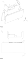
- FIG. 2 is a structural diagram showing matching between the end plate and the output pole base in FIG. 1
- FIG. 3 is a front view of FIG. 2
- FIG. 4 is a bottom view of FIG. 2
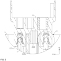
- FIG. 5 is a partial cross-sectional view of FIG. 3
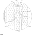
- FIG. 6 is a partial enlarged view of part I in FIG. 5
- FIG. 7 is a structural diagram of the output pole base in FIG. 2
- FIG. 8 is a front view of FIG. 7
- FIG. 9 is a bottom view of FIG. 8
- FIG. 10 is a partial enlarged view of part II in FIG. 7
- FIG. 11 is a structural diagram that the matching part is removed in FIG. 10
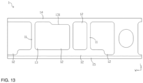
- FIG. 12 is a structural diagram of the end plate in FIG. 2
- FIG. 13 is a top view of FIG. 12 .
- the embodiment of the present application provides a battery module, which includes a housing (not shown in the figure) with an inner cavity; further includes one or more unit batteries (not shown in the figure).
- the battery module includes a plurality of unit batteries
- each unit battery is stacked in the inner cavity of the housing according to a preset rule.
- the stacking direction of each unit battery is the length direction L of the battery module.
- the housing includes two end plates 1 and two side plates, and the end plate 1 and side plate are fixedly connected to form the housing of the battery module, which function as protecting each unit battery.
- the pole column of the outermost unit battery is connected to the output pole connecting piece 3.
- the output pole connecting piece 3 of the adjacent battery module is connected to the module connecting piece 4.
- the battery module also includes an output pole base 2. As shown in FIG. 1 , both the above output pole connecting piece 3 and module connecting piece 4 are connected to the output pole base 2, which is used to provide insulation protection for the output pole connecting piece 3 and module connecting piece 4.
- the output pole base 2 includes a body 21 that has a nut arranged therein.
- the output pole connecting piece 3 and the module connecting piece 4 are all provided with bolt holes, during the connection, the bolt 5 passes through both bolt holes and is fixedly connected to the nut in the body 21.
- the output pole base 2 is located at the end of the battery module along the longitudinal direction L and is fixed to the end plate 1.
- the specific means is that a processing groove is provided on the end plate 1 (e.g., a dovetail groove), and at the same time, a bump (e.g., a dovetail bump) is arranged at the bottom of the output pole base 2 to match with the processing groove, so that the output pole base 2 and the end plate 1 are connected therebetween by means of the contour complementary matching.
- a processing groove is provided on the end plate 1 (e.g., a dovetail groove)
- a bump e.g., a dovetail bump
- this connection means there is a gap between the bump of the output pole base 2 and the processing groove of the end plate 1, and the output pole base 2 and the end plate 1 cannot be completely fixed along the length direction L, width direction W and height direction H.
- the end plate 1 is made of metal material and the output pole base 2 is made of plastic material, when the both are connected by means of contour complementary matching, the gap between the both gradually increases, which leads to the decrease of the connection reliability between the both.
- the vibration of the battery module when the vibration of the battery module is occurred, it drives the output pole base 2 to vibrate, which leads to fracture of the sampling structure connected to the output pole connecting piece 3, and causes the battery module cannot be sampled normally.
- the vibration displacement of the output pole base 2 along the height direction H is large, the connection reliability between the output pole connecting piece 3 and the unit battery pole column is decreased, thereby causing the fracture failure, and as a result, the battery module fails to work normally.
- the present application mainly solves the above technical problems by optimizing the structure of the output pole base 2.
- the output pole base 2 includes a body 21, a mounting part 22 and a matching part 23 which are fixedly connected, where the body 21 is provided with threaded holes for connecting with the output pole connecting piece 3 and the module connecting piece 4 through bolts 5, and the body 21 is made of plastic material, thus providing insulation protection for the output pole connecting piece 3 and the module connecting piece 4.
- the mounting part 22 is integrated with the body 21 and is also made of plastic material.
- the mounting part 22 is used for mounting a matching part 23 that is made of metal material, and the matching part 23 is used for fixedly connecting to the end plate 1, to limit the freedom degree of movement of the output pole base 2 relative to the end plate 1 along the height direction H, the length direction I and the width direction.
- the plastic structure of the output pole base 2 is added a matching part 23 made of metal material therein, and is fixedly connected to the end plate 1 by the matching part 23, so as to achieve the complete fixing between the output pole base 2 and the end plate 1 and reduce the risk of relative movement between the output pole base 2 and the end plate 1 during the vibration process of the battery module, thereby reducing the risk of the sampling structure fracture, improving the connection reliability between the output pole connecting piece 3 and the unit battery pole column and prolonging the service life of the battery module.
- both the matching part 23 and the end plate 1 are made of metal material, it is less likely to form a gap between the both during long-term operation, thus further prolonging the service life of the battery module.
- the fixing connection means between the above matching part 23 and the end plate 1 may be: the matching part 23 and the end plate 1 have an interference fit, so that the fixing connection between the end plate 1 and the output pole base 2 can be realized. And compared with the contour complementary matching connection between the plastic part (the output pole base) and the metal part (the end plate) in the prior art, the interference fit between the two metal parts have higher connection reliability.
- the above fixing connection means between the matching part 23 and the end plate 1 may also be: as shown in FIG. 5 , the matching 23 and the end plate 1 are both made of metal material and there is a hardness difference between the both.
- the hardness of the matching part 23 is greater than that of the end plate 1, so that the matching part 23 can penetrate into the end plate 1, or the hardness of the end plate 1 is greater than that of the matching part 23, so that the end plate 1 can penetrate into the matching part 23.
- connection reliability between the matching part 23 and the end plate 1 can be further improved by connection means of penetrating between the matching part 23 and the end plate 1, and the relative displacement between the matching part 23 and the end plate 1 along the height direction H can be reduced after the matching part 23 penetrates into the end plate 1, thereby reducing the risk of vibration of the output pole base 2 along the height direction H and improving the connection reliability between the output pole connecting piece 3 and the unit battery pole column.
- the end plate 1 includes a matching wall 11 made of metal material
- the matching part 23 includes one or more claws 231 which are made of metal material and can penetrate into the matching wall 11, that is, the hardness of the claws 231 is greater than that of the matching wall 11.
- the fixing connection between the output pole base 2 and the end plate 1 can be realized by the claws 231 and the matching wall 11.
- the matching part 23 includes two claws 231 and a first connecting plate 232, the two claws 231 are located on both sides of the matching wall 11 along the width direction W, and two ends of the first connecting plate 232 along the width direction W is connected to the two claws 231, thereby connecting the claws 231 on both sides of the matching wall 11 into a whole, improving the integrity of the matching part 23 and improving the connection reliability between the matching part 23 and the end plate 1.
- the connection reliability between the matching part 23 and the end plate 1 can be further improved, and the structures on both sides of the matching part 23 are symmetrical with respect to the matching wall 11 for each other, so that stress on the connection position between the matching part 23 and the end plate 1 can be more uniform, the risk of stress concentration can be reduced, and the service life of each component can be prolonged.
- the output pole base 2 is provided with a plurality of above matching parts 23 along the width direction W, and correspondingly, the end plate 1 is provided with a plurality of above matching walls 11, thereby further improving the connection reliability between the output pole base 2 and the end plate 1.
- the output pole base 2 includes two matching parts 23 along the width direction W, and the end plate 1 includes two matching walls 11 along the width direction W.
- the output pole base 2 is mounted above the end plate 1, and the claw 231 is inclined with respect to the matching wall 11, and the inclination direction is upward.
- the output pole base 2 when the battery module is assembled, the output pole base 2 is press-mounted to the end plate 1 from top to bottom. During the press-mounted process, the claw 231 of the output pole base 2 penetrates into the matching wall 11 of the end plate 1, and after penetration, the claw 231 is still inclined upward. When the output pole base 2 vibrates, it can prevent the claw 231 from coming out of the matching wall 11, thus improving the connection reliability between the both.
- the thickness of the end of the claw 231 is small, which forms the tip of the claw 231.
- the stress of the tip on the matching wall 11 is greater, thus promoting the penetration of the claw 231 into the matching wall 11.
- the claw 231 has one or more above tips, and each tip is distributed along the length direction L and is connected into a whole through the first connecting plate 232.
- the claw 231 has four above tips along the length direction L, and each tip can penetrate into the matching wall 11. It can be understood that in the present embodiment, the number of tips in the claws 231 can be set according to the size of the matching wall 11. When the size of the matching wall 11 along the length direction L is larger, the number of tips increases, and when the size of the matching wall 11 along the length direction L is smaller, the number of tips decreases. Therefore, in the present application, the number of the above tips is not limited.
- the above matching part 23 is mounted on the mounting part 22 of the output pole base 2, where as shown in FIG. 10 and FIG. 11 , the mounting part 22 is provided with a mounting groove 221 where the matching part 23 is located in the mounting groove 221 and is along the width direction W.
- the mounting groove 221 has two side walls 221a arranged opposite, and the two side walls 221a are connected therebetween by a bottom wall 221b.
- the bottom of the side wall 221a of the mounting groove 221 has a clamping groove 221c, and the bottom wall 221b of the mounting groove 221 has a first limiting portion 221d. Therefore, along the height direction H, one end of the matching part 23 is clamped in the clamping groove 221c, and the other end abuts against the first limiting portion 221d.
- the freedom degree of movement of the matching part 23 relative to the mounting part 22 along the height direction H can be limited, thereby preventing the matching part 23 from coming out of the mounting part 22 along the height direction H.
- the clamping groove 221c is inclined with respect to the height direction H, that is, there is a clamping angle between the bottom wall of the clamping groove 221c and the height direction H, and the side wall of the clamping groove 221c is not parallel with the height direction H, meanwhile, the bottom of the matching part 23 also includes a third connecting plate 234 which is inclined with respect to the height direction H, so that the third connecting plate 234 can be clamped within the clamping groove 221c and the claw 231 is inclined with respect to the height direction H.
- the first limiting portion 221d can be specifically a flange arranged at the bottom wall 221b of the mounting groove 221, and the flange protrudes toward the inside of the mounting groove 221 and extends along the longitudinal direction L, so that it can abut against the first connecting plate 232 of the matching part 23.
- the side wall 221a of the mounting groove 221 also has a second limiting portion 221e.
- the claw 231 includes two second connecting plates 233 along the length direction L, and there is a gap between the two second connecting plates 233 along the length direction L, so that the second limiting portion 221e is clamped between the two second connecting plates 223 to limit the freedom degree of the movement of the matching part 23 along the length direction L, thereby preventing the matching part 23 from coming out of the mounting part 22 along the length direction L.
- the second limiting portion 221e specifically can be a bump arranged at the side wall 221a of the mounting groove 221, and the bump protrudes toward the inside of the mounting groove 221.
- the matching part 23 is located in the mounting groove 221 of the mounting part 22, so that the freedom degree of movement of the matching part 23 along the width direction W can be limited by the two side walls 221a of the mounting groove 221, thereby preventing the matching part 23 from coming out of the mounting part 22 along the width direction W.
- the matching part 23 can be achieved to be mounted on the mounting part 22; and by the above structure, the connection reliability between the both is enabled to be higher.
- the end plate 1 has a plurality of first matching cavities 12, and both sides of the matching wall 11 have the first matching cavities 12 along the width direction W.
- the two side walls 221a of the above mounting groove 221 are respectively located inside the two first matching cavities 12, and the two portions of structures of the matching part 23 along the width direction are respectively located inside the first matching cavities 12.
- the end plate 1 includes an inner plate 14 and an outer plate 15 distributed along the length direction L, and the both are connected therebetween by the above matching wall 11.
- the inner plate 14, the outer plate 15 and the matching wall 11 enclose the first matching cavity 12.
- the end plate 1 includes a plurality of mutually spaced hollow cavity structures, so that it can reduce the weight of the end plate 1 while ensuring its high strength and rigidity, thereby improving the energy density of the battery module.
- the mounting part 22 also includes a guide portion 222.
- the end plate 1 has a second matching cavity 13, and the guide portion 222 matches with the second matching cavity 13.
- the guide portion 222 and the second matching cavity 13 function as guiding the output pole base 2, so as to achieve the mounting of the output pole base 2 and the end plate 1.
- the guide portion 222 is located between two matching parts 23, and correspondingly, the second matching cavity 13 is located between two first matching cavities 12.
- the above first matching cavity 12 and the second matching cavity 13 are arranged in the middle of the end plate 1 along the width direction W, and the second matching cavity 13 is in communication with the first matching cavity 12.
- the matching wall 11 can also be arranged between the second matching cavity 13 and the first matching cavity 12 to separate the two matching cavities and further improve the strength and rigidity of the end plate 1.
- the inner wall of the second matching cavity 13 is provided with an end plate boss 131, and the end plate boss 131 protrudes toward the inside of the second matching cavity 13 and the end plate boss 131 is provided on the inner plate 14 or the outer plate 15 of the end plate 1.
- the guide portion 222 is located between the inner plate 14 and the end plate boss 131 and is mounted with the above.
- the side wall 221a of the mounting groove 221 in the mounting part 22 is located in the first matching cavity 12 and matches the side wall of the first matching cavity 12. Therefore, in the output pole base 2 and the end plate 1, the both are in the relative position shown in FIG. 4 (the output pole base 2 is placed forward), it can achieved to be mounted.
- the guide portion 222 has a first end 222a and a second end 222b along the width direction W, where the size of the second end 222b is smaller than that of the first end 222a, and the both are connected therebetween through an inclined arc structure, so that the guide portion 222 is of a dovetail structure, and the guide portion 222 of the dovetail structure can match with an end plate provided with a dovetail groove in the prior art. It can also match with the end plate 1 provided with a square groove (as shown in FIG. 4 ) in the prior art. Therefore, the guide portion 222 of this structure makes the output pole base 2 to have higher applicability.
- the mounting part 22 has one or more convex ribs 223, and each convex rib 223 extends along the height direction H, where each convex rib 223 are arranged on the side wall 221a of the mounting groove 221 and the guide portion 222, the convex ribs 223 arranged on the side wall 221a of the mounting groove 221 abut against the inner wall of the first matching cavity 12, and the convex ribs 223 arranged on the guide portion 222 abut against the inner wall of the second matching cavity 13. Therefore, in the process of mounting the output pole base 2 and the end plate 1, the output pole base 2 is manually mounted on the end plate 1, and the abutting convex ribs 223 can play a guiding role with the inner wall of the corresponding matching cavity.
- the mounting part 22 also includes a bump 224, and the bump 224 is located above the convex rib 223.
- the bump 224 abuts against the upper end face of the end plate 1 as the output pole base 2 is mounted, so that manual operation cannot make the output pole base 2 continue to move.
- the output pole base 2 can be continuously pressed down by mechanical tooling, and the bump 224 can be flattened to realize the interference fit between the mounting part 22 and the end plate 1.
- the distributed mounting of the output pole base 2 can be achieved through the above convex ribs 223 and bumps 224, that is, the position of the output pole base 2 can be achieved to be fixed through manual pre-mounting, and then press-mounting can be receiving through tooling.
- the above mounting process can absorb the manufacturing errors of the output pole base 2 and the end plate 1, thus contributing to improving the mounting reliability.
- the cross section of the above convex rib 223 is one or more of a triangle, a diamond and a cone. At this time, the matching surface between the convex rib 223 and the inner wall of the matching cavity is small, thus reducing the friction between the both during manual mounting.
- the side wall 221a and the guide portion 222 of the mounting groove 221 in the mounting part 22 have interference fit with the matching cavity in the end plate 1.
- the interference fit structure can withstand the torque in the mounting process, and can prevent the connection reliability between the output pole base 2 and the end plate 1 from being lowered due to the torque action.
- Embodiments of the present application also provide a vehicle, which includes the battery module described in the above embodiments.
- each embodiment or implementation is described in a progressive manner, and each embodiment focuses on the differences from other embodiments, so the same and similar parts between the various embodiments can be referred to each other.
Landscapes
- Chemical & Material Sciences (AREA)
- Chemical Kinetics & Catalysis (AREA)
- Electrochemistry (AREA)
- General Chemical & Material Sciences (AREA)
- Engineering & Computer Science (AREA)
- Inorganic Chemistry (AREA)
- Aviation & Aerospace Engineering (AREA)
- Life Sciences & Earth Sciences (AREA)
- Manufacturing & Machinery (AREA)
- Sustainable Development (AREA)
- Sustainable Energy (AREA)
- Power Engineering (AREA)
- Transportation (AREA)
- Mechanical Engineering (AREA)
- Battery Mounting, Suspending (AREA)
- Connection Of Batteries Or Terminals (AREA)
Claims (12)
- Batteriemodul, dadurch gekennzeichnet, dass es Folgendes umfasst:ein Gehäuse mit einem inneren Hohlraum;eine Vielzahl von Einzelbatterien, die in dem inneren Hohlraum gestapelt sind, wobei eine Stapelrichtung der Einzelbatterien eine Längsrichtung des Batteriemoduls ist;eine Endplatte (1), die sich an einem Ende des Batteriemoduls entlang der Längsrichtung befindet, wobei die Endplatte (1) eine passende Wand (11) einschließt, die aus einem Metallmaterial hergestellt ist, eine innere Platte (14) und eine äußere Platte (15), die entlang der Längsrichtung des Batteriemoduls verteilt sind, und die beide durch die passende Wand (11) dazwischen verbunden sind;eine Ausgangspolbasis (2), die oberhalb der Endplatte (1) in einer Höhenrichtung montiert ist und aus einem Kunststoffmaterial hergestellt ist, wobei die Ausgangspolbasis (2) ein Montageteil (22) und ein passendes Teil (23) umfasst, die fest verbunden sind, wobei das Montageteil (22) konfiguriert ist, um das passende Teil (23) an der Ausgangspolbasis (2) zu montieren, das passende Teil (23) aus Metallmaterial hergestellt ist und fest mit der Endplatte (1) verbunden ist, um einen Freiheitsgrad der Bewegung der Ausgangspolbasis (2) relativ zu der Endplatte (1) entlang der Höhenrichtung, einer Breitenrichtung und der Längenrichtung zu begrenzen, wobei die Breitenrichtung eine Erstreckungsrichtung der Endplatte (1) ist;das Montageteil (22) mit einer Montagenut (221) versehen ist, das passende Teil (23) sich in der Montagenut (221) befindet, Seitenwände (221a) der Montagenut (221) eine Klemmnut (221c) haben, eine untere Wand (221b) der Montagenut (221) einen ersten begrenzenden Abschnitt (221d) hat, und die Klemmnut (221c) und der erste begrenzende Abschnitt (221d) entlang der Höhenrichtung verteilt sind;entlang der Höhenrichtung ein Ende des passenden Teils (23) in der Klemmnut (221c) eingeklemmt ist und das andere Ende gegen den ersten begrenzenden Abschnitt (221d) stößt;die Endplatte (1) erste passende Hohlräume (12) hat, die sich auf beiden Seiten der passenden Wand (11) entlang der Breitenrichtung befinden; die innere Platte (14), die äußere Platte (15) und die passende Wand (11) die ersten passenden Hohlräume (12) umschließen; unddie Seitenwände (221a) der Montagenut (221) sich in den ersten passenden Hohlräumen (12) befinden und zu den ersten passenden Hohlräumen (12) passen.
- Batteriemodul nach Anspruch 1, dadurch gekennzeichnet, dass das passende Teil (23) und die Endplatte (1) eine Presspassung haben, oder
das passende Teil (23) und die Endplatte (1) einen Härteunterschied haben, so dass das passende Teil (23) in die Endplatte (1) eindringt oder ein Abschnitt der Endplatte (1) in das passende Teil (23) eindringen kann. - Batteriemodul nach Anspruch 1 oder 2, dadurch gekennzeichnet, dass die Endplatte (1) eine passende Wand (11) umfasst, die aus Metallmaterial hergestellt ist; das passende Teil (23) eine oder mehrere Klauen (231) umfasst, die aus Metallmaterial hergestellt sind und mindestens teilweise in die passende Wand (11) eindringen.
- Batteriemodul nach Anspruch 3, dadurch gekennzeichnet, dass beide Seiten der passenden Wand (11) mit den Klauen (231) entlang der Breitenrichtung des Batteriemoduls versehen sind;
das passende Teil (23) auch eine erste Verbindungsplatte umfasst, und zwei Enden der ersten Verbindungsplatte entlang der Breitenrichtung mit den Klauen (231) verbunden sind, die sich auf zwei Seiten der passenden Wand (11) befinden. - Batteriemodul nach einem der Ansprüche 3 bis 4, dadurch gekennzeichnet, dass ein Ende der Klaue (231) eine oder mehrere Spitzen hat.
- Batteriemodul nach Anspruch 1, dadurch gekennzeichnet, dass die Seitenwände (221a) der Montagenut (221) ferner einen zweiten Begrenzungsabschnitt (221e) haben und das passende Teil (23) an dem zweiten Begrenzungsabschnitt (221e) festgeklemmt ist, um den Freiheitsgrad der Bewegung des passenden Teils (23) entlang der Längsrichtung zu begrenzen.
- Batteriemodul nach einem der Ansprüche 1 bis 6, dadurch gekennzeichnet, dass das Montageteil (22) ferner einen Führungsabschnitt (222) umfasst, die Endplatte (1) einen zweiten passenden Hohlraum (13) hat, und der Führungsabschnitt (222) zu dem zweiten passenden Hohlraum (13) passt.
- Batteriemodul nach Anspruch 7, dadurch gekennzeichnet, dass eine innere Wand des zweiten passenden Hohlraums (13) entlang der Längsrichtung mit einem Endplattenvorsprung (131) versehen ist.
- Batteriemodul nach Anspruch 7 oder 8, dadurch gekennzeichnet, dass der Führungsabschnitt (222) entlang der Breitenrichtung ein erstes Ende (222a) und ein zweites Ende (222b) hat, und dass die Größe des zweiten Endes (222b) entlang der Längenrichtung kleiner ist als die des ersten Endes (222a) entlang der Längenrichtung.
- Batteriemodul nach einem der Ansprüche 1 bis 9, dadurch gekennzeichnet, dass das Montageteil (22) eine oder mehrere konvexe Rippen (223) hat, die sich entlang der Höhenrichtung erstrecken;
ein Querschnitt der konvexen Rippe (223) eines oder mehrere von einem Dreieck, einer Raute und einem Kegel ist. - Batteriemodul nach Anspruch 10, dadurch gekennzeichnet, dass das Montageteil (22) ferner einen Höcker (224) umfasst, der sich oberhalb der konvexen Rippe (223) befindet.
- Fahrzeug, dadurch gekennzeichnet, dass es ein Batteriemodul nach einem der Ansprüche 1 bis 11 umfasst.
Applications Claiming Priority (2)
| Application Number | Priority Date | Filing Date | Title |
|---|---|---|---|
| CN201910298777.3A CN111834560B (zh) | 2019-04-15 | 2019-04-15 | 一种电池模组 |
| PCT/CN2020/084060 WO2020211694A1 (zh) | 2019-04-15 | 2020-04-09 | 一种电池模组及车辆 |
Publications (3)
| Publication Number | Publication Date |
|---|---|
| EP3799154A1 EP3799154A1 (de) | 2021-03-31 |
| EP3799154A4 EP3799154A4 (de) | 2021-10-06 |
| EP3799154B1 true EP3799154B1 (de) | 2025-03-26 |
Family
ID=72838013
Family Applications (1)
| Application Number | Title | Priority Date | Filing Date |
|---|---|---|---|
| EP20791514.1A Active EP3799154B1 (de) | 2019-04-15 | 2020-04-09 | Batteriemodul und fahrzeug |
Country Status (4)
| Country | Link |
|---|---|
| US (1) | US12199297B2 (de) |
| EP (1) | EP3799154B1 (de) |
| CN (1) | CN111834560B (de) |
| WO (1) | WO2020211694A1 (de) |
Families Citing this family (6)
| Publication number | Priority date | Publication date | Assignee | Title |
|---|---|---|---|---|
| CN113314808A (zh) * | 2021-06-04 | 2021-08-27 | 厦门海辰新能源科技有限公司 | 一种电池极柱、动力电池及其电池模组 |
| CN116315464B (zh) * | 2021-12-13 | 2025-09-19 | 宁德时代新能源科技股份有限公司 | 一种输出极底座、电池及用电装置 |
| WO2024082298A1 (zh) * | 2022-10-21 | 2024-04-25 | 宁德时代新能源科技股份有限公司 | 电池模组、电池及用电设备 |
| CN116014367B (zh) * | 2023-01-10 | 2024-07-23 | 厦门海辰储能科技股份有限公司 | 输出极组件、电池模组、储能装置及用电设备 |
| CN116130854B (zh) * | 2023-03-03 | 2025-01-07 | 厦门海辰储能科技股份有限公司 | 电池模组与用电设备 |
| CN220895760U (zh) * | 2023-08-31 | 2024-05-03 | 惠州亿纬锂能股份有限公司 | 电池模组及电池包 |
Family Cites Families (24)
| Publication number | Priority date | Publication date | Assignee | Title |
|---|---|---|---|---|
| KR100904373B1 (ko) * | 2004-12-24 | 2009-06-25 | 주식회사 엘지화학 | 이차전지 모듈용 방열 구조물, 및 그것을 포함하는 스위칭보드 및 이차전지 모듈 |
| CN101047288A (zh) * | 2007-04-28 | 2007-10-03 | 博罗立峰开关实业有限公司 | 电池弹片模组 |
| JP2013020855A (ja) * | 2011-07-12 | 2013-01-31 | Sanyo Electric Co Ltd | 電源装置及び電源装置を備える車両 |
| JP6001360B2 (ja) * | 2012-07-05 | 2016-10-05 | 株式会社デンソー | 電池ユニット |
| CN103490024B (zh) * | 2013-09-17 | 2015-09-09 | 东风汽车公司 | 一种集成式动力电池组件 |
| FR3010834B1 (fr) * | 2013-09-18 | 2017-01-27 | Valeo Systemes Thermiques | Dispositif de regulation thermique d'un pack-batterie |
| KR101696314B1 (ko) * | 2014-08-22 | 2017-01-13 | 주식회사 엘지화학 | 배터리 모듈 및 이를 포함하는 배터리 팩 |
| JP6651457B2 (ja) * | 2014-11-07 | 2020-02-19 | 三洋電機株式会社 | 電源装置 |
| US9583747B2 (en) * | 2015-01-08 | 2017-02-28 | Ford Global Technologies, Llc | Retention assembly for traction battery cell array |
| CN204858060U (zh) * | 2015-07-29 | 2015-12-09 | 苏州纽东精密制造科技有限公司 | 一种下连片 |
| CN106531913B (zh) * | 2015-09-15 | 2022-12-13 | 北京普莱德新能源电池科技有限公司 | 一种方形电池模组 |
| CN204991808U (zh) * | 2015-09-15 | 2016-01-20 | 北京普莱德新能源电池科技有限公司 | 一种方形电池模组 |
| CN206727133U (zh) * | 2017-05-15 | 2017-12-08 | 宁德时代新能源科技股份有限公司 | 电池模组 |
| CN206947426U (zh) * | 2017-05-16 | 2018-01-30 | 芜湖天量电池系统有限公司 | 输出极绝缘装置及具有其的锂电池模组 |
| CN109273650B (zh) * | 2017-07-18 | 2021-06-04 | 宁德时代新能源科技股份有限公司 | 电池模组 |
| CN207345536U (zh) * | 2017-09-28 | 2018-05-11 | 奇瑞汽车股份有限公司 | 一种电池包低压线束接插件固定结构 |
| CN108023044B (zh) * | 2017-12-01 | 2021-08-27 | 李龙德 | 新能源车型蓄电池及bmu组件 |
| CN207743290U (zh) * | 2018-01-31 | 2018-08-17 | 宁德时代新能源科技股份有限公司 | 电池模组 |
| CN207896173U (zh) * | 2018-03-23 | 2018-09-21 | 宁德时代新能源科技股份有限公司 | 电池模组 |
| CN208336330U (zh) * | 2018-06-22 | 2019-01-04 | 宁德时代新能源科技股份有限公司 | 隔离板组件及电池模组 |
| CN208507805U (zh) * | 2018-08-15 | 2019-02-15 | 宁德时代新能源科技股份有限公司 | 连接器及电池产品 |
| CN109192891A (zh) * | 2018-08-31 | 2019-01-11 | 西华大学 | 一种电动汽车用电池防震装置 |
| CN208674174U (zh) * | 2018-09-26 | 2019-03-29 | 宁德时代新能源科技股份有限公司 | 电池模组 |
| CN208819951U (zh) * | 2018-10-17 | 2019-05-03 | 宁德时代新能源科技股份有限公司 | 电池模组及其保护组件 |
-
2019
- 2019-04-15 CN CN201910298777.3A patent/CN111834560B/zh active Active
-
2020
- 2020-04-09 EP EP20791514.1A patent/EP3799154B1/de active Active
- 2020-04-09 WO PCT/CN2020/084060 patent/WO2020211694A1/zh not_active Ceased
-
2021
- 2021-10-15 US US17/502,452 patent/US12199297B2/en active Active
Also Published As
| Publication number | Publication date |
|---|---|
| EP3799154A4 (de) | 2021-10-06 |
| CN111834560B (zh) | 2021-12-07 |
| US12199297B2 (en) | 2025-01-14 |
| US20220037729A1 (en) | 2022-02-03 |
| CN111834560A (zh) | 2020-10-27 |
| EP3799154A1 (de) | 2021-03-31 |
| WO2020211694A1 (zh) | 2020-10-22 |
Similar Documents
| Publication | Publication Date | Title |
|---|---|---|
| EP3799154B1 (de) | Batteriemodul und fahrzeug | |
| US5308716A (en) | Battery pack retention apparatus | |
| EP2571078B1 (de) | Batteriemodul | |
| EP3599652B1 (de) | Isolationsplattenanordnung und batteriemodul | |
| US9929427B2 (en) | Battery module having reinforcing barrier with metal member | |
| EP2624376B1 (de) | Steckverbinder zur erkennung einer zellspannung | |
| EP3886205B1 (de) | Batteriemodul | |
| KR20170068261A (ko) | 엔드 플레이트의 구조가 개선된 배터리 모듈 및 이를 위한 엔드 플레이트 부재 | |
| EP2892105B1 (de) | Prüfstand | |
| KR20220085396A (ko) | 배터리 팩 및 이 배터리 팩의 제조 방법 | |
| CN113140773A (zh) | 燃料电池模块 | |
| KR20230028525A (ko) | 지지 구조 | |
| CN107607746B (zh) | 夹式探针装置 | |
| KR102852014B1 (ko) | 개선된 결합 구조를 갖는 배터리 팩 및 이를 포함하는 자동차 | |
| KR102745977B1 (ko) | 돌기 구조가 형성된 홀드다운 브라켓을 포함하는 전지팩 | |
| CN223820490U (zh) | 一种电池包稳定连接结构及电动工具 | |
| JP2010192323A (ja) | 二次電池、及び二次電池の製造方法 | |
| CN215630647U (zh) | 一种阳光房的框架连接结构 | |
| CN219626863U (zh) | 铜排保护盖及电池包 | |
| CN219739221U (zh) | 一种电池模组及其工具电池包 | |
| CN210110985U (zh) | 电池顶针 | |
| CN221487030U (zh) | 分线装置 | |
| CN222146523U (zh) | 电池、电池模组及用电设备 | |
| CN103542027A (zh) | 预压弹簧片及其组合结构与风扇 | |
| CN221363427U (zh) | 浮动压紧装置及顶升压紧机构 |
Legal Events
| Date | Code | Title | Description |
|---|---|---|---|
| STAA | Information on the status of an ep patent application or granted ep patent |
Free format text: STATUS: THE INTERNATIONAL PUBLICATION HAS BEEN MADE |
|
| PUAI | Public reference made under article 153(3) epc to a published international application that has entered the european phase |
Free format text: ORIGINAL CODE: 0009012 |
|
| STAA | Information on the status of an ep patent application or granted ep patent |
Free format text: STATUS: REQUEST FOR EXAMINATION WAS MADE |
|
| 17P | Request for examination filed |
Effective date: 20201223 |
|
| AK | Designated contracting states |
Kind code of ref document: A1 Designated state(s): AL AT BE BG CH CY CZ DE DK EE ES FI FR GB GR HR HU IE IS IT LI LT LU LV MC MK MT NL NO PL PT RO RS SE SI SK SM TR |
|
| AX | Request for extension of the european patent |
Extension state: BA ME |
|
| REG | Reference to a national code |
Ref country code: DE Free format text: PREVIOUS MAIN CLASS: H01M0002100000 Ref country code: DE Ref legal event code: R079 Ref document number: 602020048374 Country of ref document: DE Free format text: PREVIOUS MAIN CLASS: H01M0002100000 Ipc: H01M0050200000 |
|
| A4 | Supplementary search report drawn up and despatched |
Effective date: 20210906 |
|
| RIC1 | Information provided on ipc code assigned before grant |
Ipc: H01M 50/296 20210101ALI20210831BHEP Ipc: H01M 50/249 20210101ALI20210831BHEP Ipc: H01M 50/204 20210101ALI20210831BHEP Ipc: B60L 50/64 20190101ALI20210831BHEP Ipc: H01M 50/50 20210101ALI20210831BHEP Ipc: H01M 50/20 20210101AFI20210831BHEP |
|
| DAV | Request for validation of the european patent (deleted) | ||
| DAX | Request for extension of the european patent (deleted) | ||
| STAA | Information on the status of an ep patent application or granted ep patent |
Free format text: STATUS: EXAMINATION IS IN PROGRESS |
|
| 17Q | First examination report despatched |
Effective date: 20240102 |
|
| RAP1 | Party data changed (applicant data changed or rights of an application transferred) |
Owner name: CONTEMPORARY AMPEREX TECHNOLOGY(HONG KONG) LIMITED |
|
| REG | Reference to a national code |
Ref country code: DE Ref legal event code: R079 Free format text: PREVIOUS MAIN CLASS: H01M0050200000 Ipc: H01M0050224000 Ref country code: DE Ref legal event code: R079 Ref document number: 602020048374 Country of ref document: DE Free format text: PREVIOUS MAIN CLASS: H01M0050200000 Ipc: H01M0050224000 |
|
| GRAP | Despatch of communication of intention to grant a patent |
Free format text: ORIGINAL CODE: EPIDOSNIGR1 |
|
| STAA | Information on the status of an ep patent application or granted ep patent |
Free format text: STATUS: GRANT OF PATENT IS INTENDED |
|
| RIC1 | Information provided on ipc code assigned before grant |
Ipc: H01M 50/244 20210101ALI20241125BHEP Ipc: H01M 50/567 20210101ALI20241125BHEP Ipc: H01M 50/296 20210101ALI20241125BHEP Ipc: H01M 50/249 20210101ALI20241125BHEP Ipc: H01M 50/204 20210101ALI20241125BHEP Ipc: B60L 50/64 20190101ALI20241125BHEP Ipc: H01M 50/50 20210101ALI20241125BHEP Ipc: H01M 50/20 20210101ALI20241125BHEP Ipc: H01M 50/543 20210101ALI20241125BHEP Ipc: H01M 50/224 20210101AFI20241125BHEP |
|
| INTG | Intention to grant announced |
Effective date: 20241204 |
|
| GRAS | Grant fee paid |
Free format text: ORIGINAL CODE: EPIDOSNIGR3 |
|
| GRAA | (expected) grant |
Free format text: ORIGINAL CODE: 0009210 |
|
| STAA | Information on the status of an ep patent application or granted ep patent |
Free format text: STATUS: THE PATENT HAS BEEN GRANTED |
|
| AK | Designated contracting states |
Kind code of ref document: B1 Designated state(s): AL AT BE BG CH CY CZ DE DK EE ES FI FR GB GR HR HU IE IS IT LI LT LU LV MC MK MT NL NO PL PT RO RS SE SI SK SM TR |
|
| REG | Reference to a national code |
Ref country code: GB Ref legal event code: FG4D |
|
| REG | Reference to a national code |
Ref country code: CH Ref legal event code: EP |
|
| REG | Reference to a national code |
Ref country code: DE Ref legal event code: R096 Ref document number: 602020048374 Country of ref document: DE |
|
| REG | Reference to a national code |
Ref country code: IE Ref legal event code: FG4D |
|
| P01 | Opt-out of the competence of the unified patent court (upc) registered |
Free format text: CASE NUMBER: APP_19239/2025 Effective date: 20250422 |
|
| PG25 | Lapsed in a contracting state [announced via postgrant information from national office to epo] |
Ref country code: RS Free format text: LAPSE BECAUSE OF FAILURE TO SUBMIT A TRANSLATION OF THE DESCRIPTION OR TO PAY THE FEE WITHIN THE PRESCRIBED TIME-LIMIT Effective date: 20250626 |
|
| PG25 | Lapsed in a contracting state [announced via postgrant information from national office to epo] |
Ref country code: FI Free format text: LAPSE BECAUSE OF FAILURE TO SUBMIT A TRANSLATION OF THE DESCRIPTION OR TO PAY THE FEE WITHIN THE PRESCRIBED TIME-LIMIT Effective date: 20250326 |
|
| PGFP | Annual fee paid to national office [announced via postgrant information from national office to epo] |
Ref country code: DE Payment date: 20250417 Year of fee payment: 6 |
|
| REG | Reference to a national code |
Ref country code: LT Ref legal event code: MG9D |
|
| PG25 | Lapsed in a contracting state [announced via postgrant information from national office to epo] |
Ref country code: NO Free format text: LAPSE BECAUSE OF FAILURE TO SUBMIT A TRANSLATION OF THE DESCRIPTION OR TO PAY THE FEE WITHIN THE PRESCRIBED TIME-LIMIT Effective date: 20250626 |
|
| PG25 | Lapsed in a contracting state [announced via postgrant information from national office to epo] |
Ref country code: HR Free format text: LAPSE BECAUSE OF FAILURE TO SUBMIT A TRANSLATION OF THE DESCRIPTION OR TO PAY THE FEE WITHIN THE PRESCRIBED TIME-LIMIT Effective date: 20250326 |
|
| PG25 | Lapsed in a contracting state [announced via postgrant information from national office to epo] |
Ref country code: LV Free format text: LAPSE BECAUSE OF FAILURE TO SUBMIT A TRANSLATION OF THE DESCRIPTION OR TO PAY THE FEE WITHIN THE PRESCRIBED TIME-LIMIT Effective date: 20250326 |
|
| PGFP | Annual fee paid to national office [announced via postgrant information from national office to epo] |
Ref country code: FR Payment date: 20250429 Year of fee payment: 6 |
|
| PG25 | Lapsed in a contracting state [announced via postgrant information from national office to epo] |
Ref country code: BG Free format text: LAPSE BECAUSE OF FAILURE TO SUBMIT A TRANSLATION OF THE DESCRIPTION OR TO PAY THE FEE WITHIN THE PRESCRIBED TIME-LIMIT Effective date: 20250326 Ref country code: GR Free format text: LAPSE BECAUSE OF FAILURE TO SUBMIT A TRANSLATION OF THE DESCRIPTION OR TO PAY THE FEE WITHIN THE PRESCRIBED TIME-LIMIT Effective date: 20250627 |
|
| REG | Reference to a national code |
Ref country code: NL Ref legal event code: MP Effective date: 20250326 |
|
| PG25 | Lapsed in a contracting state [announced via postgrant information from national office to epo] |
Ref country code: NL Free format text: LAPSE BECAUSE OF FAILURE TO SUBMIT A TRANSLATION OF THE DESCRIPTION OR TO PAY THE FEE WITHIN THE PRESCRIBED TIME-LIMIT Effective date: 20250326 |
|
| PG25 | Lapsed in a contracting state [announced via postgrant information from national office to epo] |
Ref country code: SE Free format text: LAPSE BECAUSE OF FAILURE TO SUBMIT A TRANSLATION OF THE DESCRIPTION OR TO PAY THE FEE WITHIN THE PRESCRIBED TIME-LIMIT Effective date: 20250326 |
|
| REG | Reference to a national code |
Ref country code: AT Ref legal event code: MK05 Ref document number: 1779885 Country of ref document: AT Kind code of ref document: T Effective date: 20250326 |
|
| PG25 | Lapsed in a contracting state [announced via postgrant information from national office to epo] |
Ref country code: SM Free format text: LAPSE BECAUSE OF FAILURE TO SUBMIT A TRANSLATION OF THE DESCRIPTION OR TO PAY THE FEE WITHIN THE PRESCRIBED TIME-LIMIT Effective date: 20250326 |
|
| PG25 | Lapsed in a contracting state [announced via postgrant information from national office to epo] |
Ref country code: ES Free format text: LAPSE BECAUSE OF FAILURE TO SUBMIT A TRANSLATION OF THE DESCRIPTION OR TO PAY THE FEE WITHIN THE PRESCRIBED TIME-LIMIT Effective date: 20250326 Ref country code: PT Free format text: LAPSE BECAUSE OF FAILURE TO SUBMIT A TRANSLATION OF THE DESCRIPTION OR TO PAY THE FEE WITHIN THE PRESCRIBED TIME-LIMIT Effective date: 20250728 |
|
| PG25 | Lapsed in a contracting state [announced via postgrant information from national office to epo] |
Ref country code: PL Free format text: LAPSE BECAUSE OF FAILURE TO SUBMIT A TRANSLATION OF THE DESCRIPTION OR TO PAY THE FEE WITHIN THE PRESCRIBED TIME-LIMIT Effective date: 20250326 Ref country code: IT Free format text: LAPSE BECAUSE OF FAILURE TO SUBMIT A TRANSLATION OF THE DESCRIPTION OR TO PAY THE FEE WITHIN THE PRESCRIBED TIME-LIMIT Effective date: 20250326 |
|
| PG25 | Lapsed in a contracting state [announced via postgrant information from national office to epo] |
Ref country code: AT Free format text: LAPSE BECAUSE OF FAILURE TO SUBMIT A TRANSLATION OF THE DESCRIPTION OR TO PAY THE FEE WITHIN THE PRESCRIBED TIME-LIMIT Effective date: 20250326 |
|
| PG25 | Lapsed in a contracting state [announced via postgrant information from national office to epo] |
Ref country code: EE Free format text: LAPSE BECAUSE OF FAILURE TO SUBMIT A TRANSLATION OF THE DESCRIPTION OR TO PAY THE FEE WITHIN THE PRESCRIBED TIME-LIMIT Effective date: 20250326 |
|
| PG25 | Lapsed in a contracting state [announced via postgrant information from national office to epo] |
Ref country code: RO Free format text: LAPSE BECAUSE OF FAILURE TO SUBMIT A TRANSLATION OF THE DESCRIPTION OR TO PAY THE FEE WITHIN THE PRESCRIBED TIME-LIMIT Effective date: 20250326 |
|
| PG25 | Lapsed in a contracting state [announced via postgrant information from national office to epo] |
Ref country code: SK Free format text: LAPSE BECAUSE OF FAILURE TO SUBMIT A TRANSLATION OF THE DESCRIPTION OR TO PAY THE FEE WITHIN THE PRESCRIBED TIME-LIMIT Effective date: 20250326 |
|
| PG25 | Lapsed in a contracting state [announced via postgrant information from national office to epo] |
Ref country code: IS Free format text: LAPSE BECAUSE OF FAILURE TO SUBMIT A TRANSLATION OF THE DESCRIPTION OR TO PAY THE FEE WITHIN THE PRESCRIBED TIME-LIMIT Effective date: 20250726 |
|
| REG | Reference to a national code |
Ref country code: CH Ref legal event code: H13 Free format text: ST27 STATUS EVENT CODE: U-0-0-H10-H13 (AS PROVIDED BY THE NATIONAL OFFICE) Effective date: 20251125 |
|
| PG25 | Lapsed in a contracting state [announced via postgrant information from national office to epo] |
Ref country code: LU Free format text: LAPSE BECAUSE OF NON-PAYMENT OF DUE FEES Effective date: 20250409 |
|
| PG25 | Lapsed in a contracting state [announced via postgrant information from national office to epo] |
Ref country code: MC Free format text: LAPSE BECAUSE OF FAILURE TO SUBMIT A TRANSLATION OF THE DESCRIPTION OR TO PAY THE FEE WITHIN THE PRESCRIBED TIME-LIMIT Effective date: 20250326 |
|
| REG | Reference to a national code |
Ref country code: BE Ref legal event code: MM Effective date: 20250430 |
|
| REG | Reference to a national code |
Ref country code: DE Ref legal event code: R097 Ref document number: 602020048374 Country of ref document: DE |
|
| PG25 | Lapsed in a contracting state [announced via postgrant information from national office to epo] |
Ref country code: DK Free format text: LAPSE BECAUSE OF FAILURE TO SUBMIT A TRANSLATION OF THE DESCRIPTION OR TO PAY THE FEE WITHIN THE PRESCRIBED TIME-LIMIT Effective date: 20250326 |
|
| PG25 | Lapsed in a contracting state [announced via postgrant information from national office to epo] |
Ref country code: BE Free format text: LAPSE BECAUSE OF NON-PAYMENT OF DUE FEES Effective date: 20250430 |
|
| PG25 | Lapsed in a contracting state [announced via postgrant information from national office to epo] |
Ref country code: CH Free format text: LAPSE BECAUSE OF NON-PAYMENT OF DUE FEES Effective date: 20250430 |
|
| PG25 | Lapsed in a contracting state [announced via postgrant information from national office to epo] |
Ref country code: CZ Free format text: LAPSE BECAUSE OF FAILURE TO SUBMIT A TRANSLATION OF THE DESCRIPTION OR TO PAY THE FEE WITHIN THE PRESCRIBED TIME-LIMIT Effective date: 20250326 |
|
| PLBE | No opposition filed within time limit |
Free format text: ORIGINAL CODE: 0009261 |
|
| STAA | Information on the status of an ep patent application or granted ep patent |
Free format text: STATUS: NO OPPOSITION FILED WITHIN TIME LIMIT |
|
| REG | Reference to a national code |
Ref country code: CH Ref legal event code: L10 Free format text: ST27 STATUS EVENT CODE: U-0-0-L10-L00 (AS PROVIDED BY THE NATIONAL OFFICE) Effective date: 20260211 |
|
| 26N | No opposition filed |
Effective date: 20260105 |
|
| PGFP | Annual fee paid to national office [announced via postgrant information from national office to epo] |
Ref country code: GB Payment date: 20260327 Year of fee payment: 7 |
|
| PG25 | Lapsed in a contracting state [announced via postgrant information from national office to epo] |
Ref country code: IE Free format text: LAPSE BECAUSE OF NON-PAYMENT OF DUE FEES Effective date: 20250409 |