EP3797088B1 - Improved lithium ion battery using high surface area nanotubes - Google Patents
Improved lithium ion battery using high surface area nanotubes Download PDFInfo
- Publication number
- EP3797088B1 EP3797088B1 EP19737276.6A EP19737276A EP3797088B1 EP 3797088 B1 EP3797088 B1 EP 3797088B1 EP 19737276 A EP19737276 A EP 19737276A EP 3797088 B1 EP3797088 B1 EP 3797088B1
- Authority
- EP
- European Patent Office
- Prior art keywords
- surface area
- carbon nanotubes
- composition
- nanotubes
- poly
- Prior art date
- Legal status (The legal status is an assumption and is not a legal conclusion. Google has not performed a legal analysis and makes no representation as to the accuracy of the status listed.)
- Active
Links
Images






Classifications
-
- C—CHEMISTRY; METALLURGY
- C01—INORGANIC CHEMISTRY
- C01B—NON-METALLIC ELEMENTS; COMPOUNDS THEREOF; METALLOIDS OR COMPOUNDS THEREOF NOT COVERED BY SUBCLASS C01C
- C01B32/00—Carbon; Compounds thereof
- C01B32/15—Nano-sized carbon materials
- C01B32/158—Carbon nanotubes
- C01B32/168—After-treatment
- C01B32/174—Derivatisation; Solubilisation; Dispersion in solvents
-
- C—CHEMISTRY; METALLURGY
- C08—ORGANIC MACROMOLECULAR COMPOUNDS; THEIR PREPARATION OR CHEMICAL WORKING-UP; COMPOSITIONS BASED THEREON
- C08K—Use of inorganic or non-macromolecular organic substances as compounding ingredients
- C08K3/00—Use of inorganic substances as compounding ingredients
- C08K3/02—Elements
- C08K3/04—Carbon
-
- C—CHEMISTRY; METALLURGY
- C08—ORGANIC MACROMOLECULAR COMPOUNDS; THEIR PREPARATION OR CHEMICAL WORKING-UP; COMPOSITIONS BASED THEREON
- C08K—Use of inorganic or non-macromolecular organic substances as compounding ingredients
- C08K3/00—Use of inorganic substances as compounding ingredients
- C08K3/02—Elements
- C08K3/04—Carbon
- C08K3/041—Carbon nanotubes
-
- C—CHEMISTRY; METALLURGY
- C08—ORGANIC MACROMOLECULAR COMPOUNDS; THEIR PREPARATION OR CHEMICAL WORKING-UP; COMPOSITIONS BASED THEREON
- C08K—Use of inorganic or non-macromolecular organic substances as compounding ingredients
- C08K3/00—Use of inorganic substances as compounding ingredients
- C08K3/02—Elements
- C08K3/04—Carbon
- C08K3/042—Graphene or derivatives, e.g. graphene oxides
-
- C—CHEMISTRY; METALLURGY
- C08—ORGANIC MACROMOLECULAR COMPOUNDS; THEIR PREPARATION OR CHEMICAL WORKING-UP; COMPOSITIONS BASED THEREON
- C08K—Use of inorganic or non-macromolecular organic substances as compounding ingredients
- C08K3/00—Use of inorganic substances as compounding ingredients
- C08K3/02—Elements
- C08K3/04—Carbon
- C08K3/045—Fullerenes
-
- H—ELECTRICITY
- H01—ELECTRIC ELEMENTS
- H01M—PROCESSES OR MEANS, e.g. BATTERIES, FOR THE DIRECT CONVERSION OF CHEMICAL ENERGY INTO ELECTRICAL ENERGY
- H01M4/00—Electrodes
- H01M4/02—Electrodes composed of, or comprising, active material
- H01M4/62—Selection of inactive substances as ingredients for active masses, e.g. binders, fillers
- H01M4/621—Binders
-
- H—ELECTRICITY
- H01—ELECTRIC ELEMENTS
- H01M—PROCESSES OR MEANS, e.g. BATTERIES, FOR THE DIRECT CONVERSION OF CHEMICAL ENERGY INTO ELECTRICAL ENERGY
- H01M4/00—Electrodes
- H01M4/02—Electrodes composed of, or comprising, active material
- H01M4/62—Selection of inactive substances as ingredients for active masses, e.g. binders, fillers
- H01M4/621—Binders
- H01M4/622—Binders being polymers
-
- H—ELECTRICITY
- H01—ELECTRIC ELEMENTS
- H01M—PROCESSES OR MEANS, e.g. BATTERIES, FOR THE DIRECT CONVERSION OF CHEMICAL ENERGY INTO ELECTRICAL ENERGY
- H01M4/00—Electrodes
- H01M4/02—Electrodes composed of, or comprising, active material
- H01M4/62—Selection of inactive substances as ingredients for active masses, e.g. binders, fillers
- H01M4/624—Electric conductive fillers
- H01M4/625—Carbon or graphite
-
- H—ELECTRICITY
- H01—ELECTRIC ELEMENTS
- H01M—PROCESSES OR MEANS, e.g. BATTERIES, FOR THE DIRECT CONVERSION OF CHEMICAL ENERGY INTO ELECTRICAL ENERGY
- H01M50/00—Constructional details or processes of manufacture of the non-active parts of electrochemical cells other than fuel cells, e.g. hybrid cells
- H01M50/40—Separators; Membranes; Diaphragms; Spacing elements inside cells
- H01M50/409—Separators, membranes or diaphragms characterised by the material
- H01M50/411—Organic material
- H01M50/414—Synthetic resins, e.g. thermoplastics or thermosetting resins
-
- H—ELECTRICITY
- H01—ELECTRIC ELEMENTS
- H01M—PROCESSES OR MEANS, e.g. BATTERIES, FOR THE DIRECT CONVERSION OF CHEMICAL ENERGY INTO ELECTRICAL ENERGY
- H01M50/00—Constructional details or processes of manufacture of the non-active parts of electrochemical cells other than fuel cells, e.g. hybrid cells
- H01M50/40—Separators; Membranes; Diaphragms; Spacing elements inside cells
- H01M50/409—Separators, membranes or diaphragms characterised by the material
- H01M50/431—Inorganic material
-
- H—ELECTRICITY
- H01—ELECTRIC ELEMENTS
- H01M—PROCESSES OR MEANS, e.g. BATTERIES, FOR THE DIRECT CONVERSION OF CHEMICAL ENERGY INTO ELECTRICAL ENERGY
- H01M50/00—Constructional details or processes of manufacture of the non-active parts of electrochemical cells other than fuel cells, e.g. hybrid cells
- H01M50/40—Separators; Membranes; Diaphragms; Spacing elements inside cells
- H01M50/409—Separators, membranes or diaphragms characterised by the material
- H01M50/44—Fibrous material
-
- H—ELECTRICITY
- H01—ELECTRIC ELEMENTS
- H01M—PROCESSES OR MEANS, e.g. BATTERIES, FOR THE DIRECT CONVERSION OF CHEMICAL ENERGY INTO ELECTRICAL ENERGY
- H01M50/00—Constructional details or processes of manufacture of the non-active parts of electrochemical cells other than fuel cells, e.g. hybrid cells
- H01M50/40—Separators; Membranes; Diaphragms; Spacing elements inside cells
- H01M50/409—Separators, membranes or diaphragms characterised by the material
- H01M50/446—Composite material consisting of a mixture of organic and inorganic materials
-
- C—CHEMISTRY; METALLURGY
- C01—INORGANIC CHEMISTRY
- C01P—INDEXING SCHEME RELATING TO STRUCTURAL AND PHYSICAL ASPECTS OF SOLID INORGANIC COMPOUNDS
- C01P2004/00—Particle morphology
- C01P2004/01—Particle morphology depicted by an image
- C01P2004/03—Particle morphology depicted by an image obtained by SEM
-
- C—CHEMISTRY; METALLURGY
- C01—INORGANIC CHEMISTRY
- C01P—INDEXING SCHEME RELATING TO STRUCTURAL AND PHYSICAL ASPECTS OF SOLID INORGANIC COMPOUNDS
- C01P2006/00—Physical properties of inorganic compounds
- C01P2006/12—Surface area
-
- C—CHEMISTRY; METALLURGY
- C01—INORGANIC CHEMISTRY
- C01P—INDEXING SCHEME RELATING TO STRUCTURAL AND PHYSICAL ASPECTS OF SOLID INORGANIC COMPOUNDS
- C01P2006/00—Physical properties of inorganic compounds
- C01P2006/40—Electric properties
-
- C—CHEMISTRY; METALLURGY
- C08—ORGANIC MACROMOLECULAR COMPOUNDS; THEIR PREPARATION OR CHEMICAL WORKING-UP; COMPOSITIONS BASED THEREON
- C08K—Use of inorganic or non-macromolecular organic substances as compounding ingredients
- C08K2201/00—Specific properties of additives
- C08K2201/002—Physical properties
- C08K2201/006—Additives being defined by their surface area
-
- H—ELECTRICITY
- H01—ELECTRIC ELEMENTS
- H01M—PROCESSES OR MEANS, e.g. BATTERIES, FOR THE DIRECT CONVERSION OF CHEMICAL ENERGY INTO ELECTRICAL ENERGY
- H01M10/00—Secondary cells; Manufacture thereof
- H01M10/05—Accumulators with non-aqueous electrolyte
- H01M10/052—Li-accumulators
- H01M10/0525—Rocking-chair batteries, i.e. batteries with lithium insertion or intercalation in both electrodes; Lithium-ion batteries
-
- H—ELECTRICITY
- H01—ELECTRIC ELEMENTS
- H01M—PROCESSES OR MEANS, e.g. BATTERIES, FOR THE DIRECT CONVERSION OF CHEMICAL ENERGY INTO ELECTRICAL ENERGY
- H01M10/00—Secondary cells; Manufacture thereof
- H01M10/06—Lead-acid accumulators
-
- H—ELECTRICITY
- H01—ELECTRIC ELEMENTS
- H01M—PROCESSES OR MEANS, e.g. BATTERIES, FOR THE DIRECT CONVERSION OF CHEMICAL ENERGY INTO ELECTRICAL ENERGY
- H01M10/00—Secondary cells; Manufacture thereof
- H01M10/24—Alkaline accumulators
- H01M10/30—Nickel accumulators
-
- H—ELECTRICITY
- H01—ELECTRIC ELEMENTS
- H01M—PROCESSES OR MEANS, e.g. BATTERIES, FOR THE DIRECT CONVERSION OF CHEMICAL ENERGY INTO ELECTRICAL ENERGY
- H01M6/00—Primary cells; Manufacture thereof
- H01M6/14—Cells with non-aqueous electrolyte
- H01M6/16—Cells with non-aqueous electrolyte with organic electrolyte
-
- Y—GENERAL TAGGING OF NEW TECHNOLOGICAL DEVELOPMENTS; GENERAL TAGGING OF CROSS-SECTIONAL TECHNOLOGIES SPANNING OVER SEVERAL SECTIONS OF THE IPC; TECHNICAL SUBJECTS COVERED BY FORMER USPC CROSS-REFERENCE ART COLLECTIONS [XRACs] AND DIGESTS
- Y02—TECHNOLOGIES OR APPLICATIONS FOR MITIGATION OR ADAPTATION AGAINST CLIMATE CHANGE
- Y02E—REDUCTION OF GREENHOUSE GAS [GHG] EMISSIONS, RELATED TO ENERGY GENERATION, TRANSMISSION OR DISTRIBUTION
- Y02E60/00—Enabling technologies; Technologies with a potential or indirect contribution to GHG emissions mitigation
- Y02E60/10—Energy storage using batteries
Definitions
- the present invention is directed to a composition for use as a binder material, an electrolyte material or a separator film material of an energy storage or collection device, to a battery, to uses of carbon nanotubes, and to uses of the composition.
- Many energy storage devices like batteries, capacitors and photovoltaics can utilize a binder and/or an electrolyte and separator film to provide enhanced performances in mechanical stabilization, improved electrical conduction of the powder used in cathodes or electrodes and ion transport in the electro-or photoactive material and electrolyte.
- Lithium ion batteries are used extensively for portable electronic equipment and batteries such as lithium ion and lead-acid are increasingly being used to provide electrical back-up for wind and solar energy.
- the salts for the cathode materials in lithium ion batteries are generally known to have poor electrical conductivity and poor electrochemical stability which results in poor cycling (charge/discharge) ability.
- Both cathode and anode materials in many battery types such as lithium ion based batteries exhibit swelling and deswelling as the battery is charged and discharged. This spatial movement leads to further separation of some of the particles and increased electrical resistance.
- the high internal resistance of the batteries, particularly in large arrays of lithium ion batteries such as used in electric vehicles, can result in excessive heat generation leading to runaway chemical reactions and fires due to the organic liquid electrolyte.
- Lithium primary batteries consist, for example, of lithium, poly(carbon monofluoride) and lithium tetrafluoroborate together with a solvent such as gamma-butyrolactone as an electrolyte. These lithium primary batteries have excellent storage lifetimes, but suffer from only being able to provide low current and the capacity is about one tenth of what is theoretically possible. This is ascribed to the poor electrical conductivity of the poly(carbon monofluoride). In some cases a portion manganese dioxide is added to aid in the electrical conductivity and power of the lithium battery.
- Binders such as polyacrylic acid (PAA), for cathodes, poly(styrene butadiene), carboxymethylcellulose (CMC), styrene-butadiene (SBR), for anodes, and particularly polyvinylidene fluoride (PVDF) for cathodes and anodes, are used in lithium based batteries to hold the active material particles together and to maintain contact with the current collectors i.e., the aluminum (Al) or the copper (Cu) foil.
- PAA and SBR are used as aqueous suspensions or solutions and are considered more environmentally benign than organic solvent based systems such as n-methyl 2 pyrrolidone (NMP) with PVDF.
- a cathode electrode of a lithium ion battery is typically made by mixing active material powder, such as lithium iron phosphate, binder powder, i.e., high molecular weight PVDF, solvent such as NMP if using PVDF, and additives such as carbon black, into a slurry (paste) and pumping this slurry to a coating machine.
- active material powder such as lithium iron phosphate
- binder powder i.e., high molecular weight PVDF, solvent such as NMP if using PVDF, and additives such as carbon black
- An anode electrode for a lithium ion battery is made similarly by typically mixing graphite, or other materials such as silicon, as the active material, together with the binder, solvent and additives.
- the coating machines spread the mixed slurry (paste) on both sides of the Al foil for the cathode and Cu foil for the anode.
- the coated foil is subsequently calendared to make the electrode thickness more uniform, followed by a slitting operation for
- the positive electrode can consist of a wet powder mix of manganese dioxide, a powdered carbon black and electrolyte such as ammonium chloride and water.
- the carbon black can add electrical conductivity to the manganese dioxide particles, but is needed at high weight percentages in the range about 10 to 50% by weight of manganese dioxide. These high amounts of carbon black needed for improved electrical conductivity, or reduced impedance of the battery, diminish the capacity per unit volume of the battery as less manganese dioxide can be employed per unit volume of the positive paste mix.
- the anode can be made from carbon particles together with a binder to provide higher specific capacity (capacity per unit weight).
- the anode of a zinc-carbon battery is often a carbon rod typically made of compressed carbon particles, graphite and a binder such as pitch.
- the carbon particle anodes tend to have poor mechanical strength leading to fracture under conditions of vibration and mechanical shock.
- the characteristics of the binder material are important for both manufacturing and performance of the battery. Some of these characteristics of relevance are electrical and ionic conductivity, tensile strength and extensibility, adhesion to particles as well as the foils, and swelling of electrolyte. Improvement of electrical and ionic conductivity is needed for improved battery capacity and power. Materials such as lithium manganese oxide for cathodes and silicon particles for anodes exhibit much lower practical specific capacity than theoretically available. A higher electrical and ionic conductivity binder material would be most beneficial to achieve specific capacities closer to their theoretical values. It is desirable to improve the tensile and adhesive strength of binders so that less binder material can be employed and also improve the battery cycling lifetime.
- the layer thickness of the binder can be as thin as 50 to 100 nanometers. This layer thickness precludes uniform distributions of particles of sizes larger than the binder layer thickness.
- multiwall carbon nanotubes as usually made in a gas phase reactor consist of bundles with diameters ranging from about 50 to 500 microns in diameter and would therefor reside only at the interstitial spaces between the particles.
- Impurities such as non-lithium salts, iron, and manganese to name a few
- the binder can also be highly deleterious to battery performance.
- high purity of the binder material, and other additives comprising the binder material is an important factor to minimize unwanted side reactions in the electrochemical process.
- the total iron in the manganese dioxide is less than 100 ppm to prevent hydrogen gassing at the anode.
- the impurity residue of the nanotubes employed herein may be less than about 5 weight percent, or less than about 2 weight percent, or less than about 1 weight percent.
- lines of conductive paste ink are screen-printed onto solar panel modules.
- the binders are usually polymer based for improved printability, such as ETHOCEL TM (Dow Chemical Company). During the burning off of the polymer and cooling the lines can crack due to shrinkage forces and so increase impedance. It is highly desirable to have a more robust conductive paste ink to prevent cracking during heating and cooling.
- ionic liquids for example, ethyl-methyl-imidazolium bis-(trifluoromethanesulfonyl)-imide (EMI-TFSI), and solid polymer, sometimes with additional additives, for example, polyethylene oxide with titanium dioxide nanoparticles, or inorganic solid electrolytes such as a ceramic or glass of the type glass ceramics, Li 1 + x + y Ti 2 - x Al x Si y P 3 - y O 12 (LTAP).
- the electrical conductivity values of organic liquid electrolytes are in the general range of 10 -2 to 10 -1 S/cm.
- Polymer electrolytes have electrical conductivity values in the range of about 10 -7 to 10 -4 S/cm, dependent on temperature, whereas inorganic solid electrolytes generally have values in the range 10 -8 to 10 -5 S/cm. At room temperature most polymer electrolytes have electrical conductivity values around 10 -5 S/cm.
- the low ionic conductivities of polymer and inorganic solid electrolytes are presently a limitation to their general use in energy storage and collection devices. It is thus highly desirable to improve the conductivity of electrolytes, and particularly with polymer and inorganic electrolytes because of their improved flammability characteristics relative to organic liquids. Also, it is desirable to improve the mechanical strength of solid electrolytes in battery applications requiring durability in high vibration or mechanical shock environments, as well as in their ease of device fabrication.
- the electrolyte In alkaline batteries the electrolyte is typically potassium hydroxide. Alkaline batteries are known to have significantly poorer capacity on high current discharge than low current discharge. Electrolyte ion transport limitations as well as polarization of the zinc anode are known reasons for this. An increase in the electrolyte ion transport is highly desirable.
- DSSCs dye sensitized solar cells
- One of the most serious drawbacks of the present DSSCs technology is the use of liquid and corrosive electrolytes which strongly limit their commercial development.
- An example of an electrolyte currently used for DSSCs is potassium iodide/iodine. Replacement of the presently used electrolytes is desirable, but candidate electrolytes have poor ion transport.
- Typical electrolytic capacitors are made of tantalum, aluminum, or ceramic with electrolyte systems such as boric acid, sulfuric acid or solid electrolytes such as polypyrrole. Improvements desired include higher rates of charge and discharge which is limited by ion transport of the electrolyte.
- a separator film is often added in batteries or capacitors with liquid electrolytes to perform the function of electrical insulation between the electrodes yet allowing ion transport.
- the separator film is a porous polymer film, the polymer being, for example a polyethylene, polypropylene, or polyvinylidene fluoride. Porosity can be introduced, for example, by using a matt of spun fibers or by solvent and/or film stretching techniques.
- the separator film is conventionally a glass fiber matt.
- the polymer separator film comprising high-surface area carbon nanotubes of this invention can improve ion transport yet still provide the necessary electrical insulation between the electrodes.
- Carbon nanotubes can be classified by the number of walls in the tube, single-wall, double wall and multiwall. Carbon nanotubes are currently manufactured as agglomerated nanotube balls, bundles or forests attached to substrates. Once removed from the substrate, manufactured nanotubes often form tight "tree-trunk” like arrangements. The use of carbon nanotubes as a reinforcing agent in composites is an area in which carbon nanotubes are predicted to have significant utility. However, utilization of carbon nanotubes in these applications has been hampered due to the general inability to reliably produce higher-surface area carbon nanotubes and the ability to disperse carbon nanotubes in a matrix.
- US-A-2017/114210 describes a composite comprising at least one epoxy resin and a plurality of discrete oxidized carbon nanotubes.
- US-A-2017/292063 describes a composition comprising discrete, individualized oxidized carbon nanotubes, at least one degradative molecule that is attached on the interior or exterior surface of the plurality of discrete carbon nanotubes, and at least one polymer.
- US-A- 2016/095940 describes a composition comprising a plurality of functionalized discrete carbon nanotubes, and at least one type of payload molecule comprising paclitaxel, and a polymer.
- US-A-2012/328940 describes a composition for lead battery comprising a plurality of discrete carbon nanotube fibers, at least one polymer, and at least one surfactant or dispersing aid.
- F. Pico et al., Single-Walled Carbon Nanotubes as Electrodes in Supercapacitors, Journal of The Electrochemical Society, 2004, 151, 6, 831-837 discloses a composition comprising oxidized single-wall nanotubes and polyvinylidene fluoride (PVDF).
- PVDF polyvinylidene fluoride
- High-surface area carbon nanotubes are formed by fibrillation of manufactured or purchased nanotubes. This fibrillation of nanotube is caused by a combination of targeted oxidation, and shear forces, such as generated by sonication. Fibrillation of the tree-truck agglomerates causes the nanotubes to loosen, exposing the surface or a greater number of nanotubes and/or a greater portion of the surface the nanotubes to the surrounding environment. This allows for increased interaction between the surrounding materials and the exposed surface of the nanotubes.
- Functionalized carbon nanotubes of the present disclosure generally refer to the chemical modification of any of the carbon nanotube types described hereinabove. Such modifications can involve the nanotube ends, sidewalls, or both. Chemical modifications may include, but are not limited to covalent bonding, ionic bonding, chemisorption, intercalation, surfactant interactions, polymer wrapping, cutting, solvation, and combinations thereof. In some embodiments, the carbon nanotubes may be functionalized before, during and after being exfoliated partially or fully.
- a plurality of carbon nanotubes comprising single wall carbon nanotubes having an aspect ratio of at least 50, or at least 100, or at least 250, or at least 500, or at least 700, or at least 1,000, or at least 1,500, or at least or 2,000 up to 6000, or up to 5000, and an overall (total) oxidation level of from about 0.1 weight percent to about 15 weight percent, preferably from 0.5 weight percent to 10 weight percent, more preferably from 1 weight percent to 5 weight percent, more preferably from 1 weight percent to 3 weight percent, or from 0.1 weight percent to 5 weight percent.
- the oxidation level is defined as the amount by weight of oxygenated species covalently bound to the carbon nanotube.
- the oxidation level may be 0, or at least 0.01 weight percent up to 2 weight percent. In other embodiments the oxidation level may be from at least 2 weight percent up to 5 weight percent.
- the thermogravimetric method for the determination of the percent weight of oxygenated species on the carbon nanotube involves taking 7-15 mg of the dried oxidized carbon nanotube and heating at 5 °C/minute from 100 degrees centigrade to 700 degrees centigrade in a dry nitrogen atmosphere. The percentage weight loss from 200 to 600 degrees centigrade is taken as the percent weight loss of oxygenated species.
- the oxygenated species can also be quantified using Fourier transform infra-red spectroscopy, FTIR, particularly in the wavelength range 1730-1680 cm -1 . In some embodiments the oxidation level may be 0%.
- the carbon nanotubes can have oxidation species comprising carboxylic acid or derivative carbonyl containing species.
- the derivative carbonyl species can include phenols, ketones, quaternary amines, amides, esters, acyl halogens, monovalent metal salts and the like, and can vary between the inner and outer surfaces of the tubes.
- one or more types of acid can be used to oxidize the tubes exterior surfaces, followed by water washing and the induced shear, thereby breaking and/or partially separating the tubes.
- the formed nanotubes or high-surface area bundles, having essentially no (or zero) interior tube wall oxidation can be further oxidized with a different oxidizing agent, or even the same oxidizing agent as that used for the tubes' exterior wall surfaces at a different concentration, resulting in differing amounts - and/or differing types - of interior and surface oxidation.
- the high-surface area nanotubes have at least 10% greater surface area after treatment than before. In other embodiments, the high-surface area nanotubes have at least 20%, at least 30%, at least 50%, at least 75%, or at least 100% greater surface area after treatment than before. In some embodiments, the high-surface area nanotubes have at least 2.5x, at least 3x, at least 5x, at least 7x, at least 10x, or at least 20x greater surface area after treatment than before.
- BET surface area of nanotubes may be measured using N 2 BET isotherms according to ASTM D6556-16.
- the BET surface area of the nanotubes herein may vary depending upon the type of nanotubes, treatment methods, and desired applications.
- the single and double walled nanotubes treated with shear, oxidation, or both that are described herein have a BET surface area of or at least 700 m 2 /g, or at least 750 m 2 /g, or at least 800 m 2 /g, or at least 850 m 2 /g, or at least 900 m 2 /g, or at least 1000 m 2 /g, or at least 1100 m 2 /g, or at least 1200 m 2 /g, or at least 1300 m 2 /g, or at least 1400 m 2 /g.
- Nanotube surface area may be measured using known methods including but not limited to gas adsorption techniques such as, for example, BET analysis, nitrogen, argon, and/or carbon dioxide adsorption. These measurements may be conducted isothermally.
- gas adsorption techniques such as, for example, BET analysis, nitrogen, argon, and/or carbon dioxide adsorption. These measurements may be conducted isothermally.
- the high-surface area nanotubes have a measured surface after being treated 25%, 40%, 55%, 80%, or 95% greater than the measured surface area prior to treatment.
- the high-surface area nanotubes have a measured surface after being treated 2x, 3x, 4x, 5x, 7x, 10x, or 15x greater than the measured surface area prior to treatment.
- high-surface area carbon nanotubes have a surface area greater than 300m 2 /g, 500m 2 /g, 700m 2/ g or 1000m 2 /g. In other embodiments, high-surface area carbon nanotubes have a surface area less than 1000 m 2 /g or 1500m 2 /g.
- As-made carbon nanotubes using metal catalysts such as iron, aluminum or cobalt can retain a significant amount of the catalyst associated or entrapped within the structure of the carbon nanotubes, as much as five weight percent or more. These residual metals can be deleterious in such applications as electronic devices because of enhanced corrosion or can interfere with the vulcanization process in curing elastomer composites. Furthermore, these divalent or multivalent metal ions can associate with carboxylic acid groups on the carbon nanotube and interfere with the loosening and/or dispersion processes.
- metal catalysts such as iron, aluminum or cobalt
- the oxidized carbon nanotubes comprise a residual metal concentration of less than 10,000 parts per million, ppm, less than 5,000 ppm, less than 3,000 ppm, less than 1,000 ppm, or be substantially free from residual metals.
- the metals can be conveniently determined using energy dispersive X-ray spectroscopy or thermogravimetric methods.
- Bosnyak et al. in various patent applications (e.g., US 2012-0183770 A1 and US 2011-0294013 A1 ), have made discrete carbon nanotubes through judicious and substantially simultaneous use of oxidation and shear forces, thereby oxidizing both the inner and outer surface of the nanotubes, typically to approximately the same oxidation level on the inner and outer surfaces, resulting in individual or discrete tubes.
- the present inventions differ from those earlier Bosnyak et al. applications and disclosures.
- the present inventions describe a composition of high-surface area carbon nanotubes having targeted, or selective, oxidation levels and/or content on the exterior and/or interior of the tube walls.
- Such novel carbon nanotubes can have little to no inner tube surface oxidation, or differing amounts and/or types of oxidation between the tubes' inner and outer surfaces.
- These new nanotubes are useful in many applications, including binder material, electrolyte material, separator film material, and or composites for energy storage devices for the improvement of mechanical, electrical, and thermal properties.
- compositions comprising a plurality of high-surface area carbon nanotubes, wherein the high-surface area carbon nanotubes comprise an interior and exterior surface, each surface comprising an interior surface oxidized species content and an exterior surface oxidized species content, wherein the interior surface oxidized species content differs from the exterior surface oxidized species content by at least 20%, and as high as 100%, preferably wherein the interior surface oxidized species content is less than the exterior surface oxidized species content.
- the interior surface oxidized species content can be up to 3 weight percent relative to carbon nanotube weight, preferably from 0.01 to 3 weight percent relative to carbon nanotube weight, more preferably from 0.01 to 2, most preferably from 0.01 to 1. Especially preferred interior surface oxidized species content is from zero to 0.01 weight percent relative to carbon nanotube weight.
- the exterior surface oxidized species content can be from 1 to 6 weight percent relative to carbon nanotube weight, preferably from 1 to 4, more preferably from 1 to 2 weight percent relative to carbon nanotube weight. This is determined by comparing the exterior oxidized species content for a given plurality of nanotubes against the total weight of that plurality of nanotubes.
- the interior and exterior surface oxidized species content totals can be from 1 to 9 weight percent relative to carbon nanotube weight.
- compositions comprising a plurality of high-surface area carbon nanotubes, wherein the high-surface area carbon nanotubes comprise an interior and exterior surface, each surface comprising an interior surface and an exterior surface oxidized species content, wherein the interior surface oxidized species content comprises from 0.01 to less than 1 percent relative to carbon nanotube weight and the exterior surface oxidized species content comprises more than 1 to 3 percent relative to carbon nanotube weight.
- compositions comprising a plurality of high-surface area carbon nanotubes, wherein at least a portion of the high-surface area carbon nanotubes are open ended, wherein the composition comprises a binder material, an electrolyte material a separator film, or a composite material for an energy storage or collection device.
- the composition comprises a plurality of high-surface area carbon nanotubes in which at least a portion of the carbon nanotubes are open ended and ion conducting.
- the composition can further comprise at least one polymer.
- the polymer is selected from the group consisting of vinyl polymers, preferably poly(styrene-butadiene), partially or fully hydrogenated poly(styrene butadiene) containing copolymers, functionalized poly(styrene butadiene) copolymers such as carboxylated poly(styrene butadiene) and the like, poly(styrene-isoprene), poly(methacrylic acid), poly(acrylic acid), poly(vinylalcohols), and poly(vinylacetates), fluorinated polymers, preferably poly(vinylidine difluoride) and poly(vinylidene difluoride) copolymers, conductive polymers, preferably poly(acetylene), poly(phenylene), poly(
- polymers that may be employed include, for example, carboxymethyl cellulose or a salt thereof such as an alkali metal salt or an alkaline earth metal salt and in particular the sodium salt, cellulose-based polymers, hydrophilic polymers with aqueous solubility over 1% w/v, polystyrene sulfonate or a salt thereof such as an alkali metal salt or an alkaline earth metal salt and in particular the sodium salt. Hydrophilic polymers may be preferable in some embodiments.
- the plurality of high-surface area carbon nanotubes are further functionalized, preferably the functional group comprises a molecule of mass greater than 50g/mole, and more preferably the functional group comprises carboxylate, hydroxyl, ester, ether, or amide moieties, or mixtures thereof.
- the composition comprises a plurality of high-surface area carbon nanotubes and at least one dispersion aid.
- the plurality of carbon nanotubes may further comprise additional inorganic structures comprising of elements of the groups two through fourteen of the Periodic Table of Elements.
- These inorganic structures can be in the form of particles, layers or as continuous media.
- Preferred inorganic structures include electrically conducting inorganic structures such as, but not limited to, silver or copper, magnetic inorganic structures such as, but not limited to, iron oxide and low melting point inorganic structures such as, but not limited to, indium-tin alloys
- the composition may comprise a plurality of carbon wherein the composition has a flexural strength of at least ten percent higher than a comparative composition made without the plurality of high-surface area carbon nanotubes.
- a binder, electrolyte or separator film composition comprising a plurality of high-surface area carbon nanotubes having a portion of carbon nanotubes that are open ended and ion conducting.
- the composition further comprises other carbon structures.
- the other carbon structures may comprise components selected from the group consisting of carbon black, graphite, graphene, oxidized graphene, fullerenes and mixtures thereof.
- the graphene or oxidized graphene have at least a portion of high-surface area carbon nanotubes interspersed between the graphene or oxidized graphene platelets.
- composition comprising a plurality of high-surface area carbon nanotubes where the binder material has an impedance of less than or equal to one billion (1 ⁇ 10 9 ) ohm-m and the electrolyte material has a charge transfer resistance of less than or equal to 10 million (1 ⁇ 10 7 ) ohm-m.
- an electrolyte or separator film composition comprising a plurality of high-surface area carbon nanotubes wherein the carbon nanotubes are oriented.
- the orientation is accomplished by fabrication techniques such as in a sheet, micro-layer, micro-layer with vertical film orientation, film, molding, extrusion, or fiber spinning fabrication method.
- the orientation may also be made via post fabrication methods, such as tentering, uniaxial orientation, biaxial orientation and thermoforming.
- the orientation may also be introduced by 3-D printing techniques.
- the oriented carbon nanotubes may be extracted from the oriented fiber or sheet containing the oriented carbon nanotubes by removal of the matrix material, such as, but not limited to, using a liquid solvent to dissolve a polymer matrix, acid to dissolve an inorganic matrix or degradation of the matrix by chemical means.
- the composition may comprise a plurality of high-surface area carbon nanotubes wherein the portion of open ended tubes comprise electrolyte.
- the polymer is preferred to comprise a molecular weight of the polymer less than 10,000 daltons, such that the polymer can enter within the tube.
- the electrolyte may contain liquids.
- the composition includes a plurality of high-surface area carbon nanotubes, and wherein at least a portion of the high-surface area carbon nanotubes are open ended.
- the disclosed high-surface area nanotubes include increased length and diameter bundles wherein at least 5% of the nanotubes have a portion of their outer surface exposed to the surrounding environment.
- Such high-surface area nanotubes include defribillated bundles.
- the bundles may have an average length of at least 400nm, 800nm, 1 ⁇ m, 10 ⁇ m, 50 ⁇ m, 100 ⁇ m, 500 ⁇ m, 1,000 ⁇ m, 1,250 ⁇ m, 1,400 ⁇ m, 1,500 ⁇ m, 1,600 ⁇ m, 1,800 ⁇ m, 2,000 ⁇ m, 3,000 ⁇ m, or 5,000 ⁇ m.
- Such bundles may have a diameter of 1 ⁇ m, or 3 ⁇ m, or 5 ⁇ m, or 7 ⁇ m, or 8 ⁇ m, or 9 ⁇ m, or 10 ⁇ m, or 12 ⁇ m.
- the high-surface area carbon nanotubes are bundles of singled walled nanotubes with individual aspect ratios of at least 50, at least 100, at least 300, at least 500, at least 700, at least 900, at least 1,000, at least 1,200, at least 1,500, or at least 2,000.
- a bimodal distribution is a continuous probability distribution with two different modes. These appear as distinct peaks (local maxima) in the probability density function. More generally, a multimodal distribution is a continuous probability distribution with two or more modes.
- the high-surface area carbon nanotubes can have a unimodal, bimodal or multimodal distribution of diameters and/or lengths both for the individual nanotubes which make up a high-surface area bundle and for the high-surface area bundles themselves. These compositions are useful in binders and electrolytes.
- an electrode paste preferably an anode paste, for a lead acid battery
- the paste comprising high-surface area carbon nanotubes having an average length and/or high-surface area bundle length of at least 1 ⁇ m, 5 ⁇ m, 10 ⁇ m, 50 ⁇ m, 100 ⁇ m, 500 ⁇ m, 1,000 ⁇ m, 1,250 ⁇ m, 1,400 ⁇ m, 1,500 ⁇ m.
- the embodiment further comprising, dispersing aids such as, but not limited to, polyvinyl alcohol, water, lead oxide and/or sulfuric acid.
- the carbon nanotubes, dispersing aid, and water form a dispersion, and the dispersion is then contacted with lead oxide followed by sulfuric acid to form the electrode paste.
- suitable solvents include, for example, renewable solvents such as cyrene (Dihydrolevoglucosenone) or solvents miscible with, for example, deionized water.
- composition consisting of high-surface area carbon nanotubes, wherein the high-surface area carbon nanotubes are coated with water, oils, waxes, nitric acid, or sulfuric acid. This coating reduces and/or prevents the formation of Van der Waals, electrical, or electrostatic forces between the carbon nanotubes, thereby preventing the high-surface area carbon nanotubes from agglomerating into a tight bundle, thereby reducing the exposed surface area of the carbon nanotubes, CNT.
- the composition may comprise as much as 99% composite material and as little as 0.025% carbon nanotubes by weight, or as little as 1% carbon nanotubes by weight. In other embodiments, the composition may contain as much as 2% CNTs, or as much as 3% CNTs, or as much as 5% CNTs, or as much as 7% CNTs, or as much as 10% CNTs, or as much as 15% CNTs, or as much as 25% CNTs by weight. Removing the water or other coating material from the composite by drying could lead to the formation of anhydride, Van der Waals, electrostatic, or other bonds between the carbon nanotubes.
- the high-surface area carbon nanotubes of any composition embodiment above comprise a plurality of open ended tubes, preferably the plurality of high-surface area carbon nanotubes comprise a plurality of open ended tubes.
- the high-surface area carbon nanotubes of any composition embodiment above are especially preferred wherein the inner and outer surface oxidation difference is at least 0.2 weight percent.
- compositions described herein can be used as an ion transport.
- Various species or classes of compounds/drugs/chemicals which demonstrate this ion transport effect can be used, including ionic, some non-ionic compounds, hydrophobic or hydrophilic compounds.
- the new carbon nanotubes disclosed herein are also useful in ground water remediation.
- compositions comprising the novel high-surface area targeted oxidized carbon nanotubes can also be used as a component in, or as, a sensor.
- compositions disclosed herein can also be used as a component in, or as, drug delivery or controlled release formulations.
- compositions disclosed herein may be used as a structural scaffolding for catalysts.
- catalysts, enzymes, proteins, peptides or other small or large molecules may be attached to the exterior of the disclosed carbon nanotubes.
- the disclosed nanotube scaffolding may be useful for positioning the attached catalysts within a matrix, positioning multiple catalytic proteins or molecules with respect to each other.
- Magnetic particles may be bound or attached to the carbon nanotubes disclosed herein.
- the bound magnetic particles may be used to influence the orientation, location, or position of the carbon nanotube to which the magnetic particle is attached. Applying a magnetic field to carbon nanotubes bound to magnetic particles may allow the carbon nanotube to be moved to a particular location.
- Magnetic fields may be generated by natural magnets or electro-magnetic devices including at least, MRI, fMRI, or pulsed electromagnetic field generator devices. Additionally, a single magnetic field generation device may be utilized or multiple magnetic field generation devices may be used.
- an array of EMF generators may be used to move CNTs bound to magnetic particles and/or cause such CNTs to vibrate, rotate, oscillate, or to direct CNTs from one specific position to another.
- More than one species of magnetic particle may be bound to a single carbon nanotube.
- the distinct species of magnetic particle may behave differently in the same magnetic field, thus creating an increased variety of possibilities for impacting the behavior of carbon nanotubes attached to more than one species of magnetic particle.
- Magnetic particles bound to carbon nanotubes may comprise 0.001 weight percent relative to carbon nanotube weight, or may comprise 0.01 weight percent relative to carbon nanotube weight, or may comprise 0.1 weight percent relative to carbon nanotube weight, or may comprise 1 weight percent relative to carbon nanotube weight, or may comprise 10 weight percent relative to carbon nanotube weight, or may comprise up to 50 weight percent relative to carbon nanotube weight, or may comprise up to 90 weight percent relative to carbon nanotube weight.
- Carbon nanotubes bound to magnetic particles may additionally contain a payload molecule as discussed above or have peptides, small molecules, nucleic acids, or other drugs or molecules attached to their exterior. These combinations may allow the nanotube, along with its associated payload or substantially non-magnetic attached molecule to be directed to a particular location where the payload molecule of the attached molecule may be desired. In this manner, targeted molecules could be delivered to a particular location using a controlled magnetic field.
- magnetic fields may be used in order to flex or distort carbon nanotubes or a network, matrix, or scaffold of carbon nanotubes. If an open ended, payload carrying nanotube is flexed or distorted as described, this may increase the rate at which the interior payload molecule is emptied into the surrounding environment thereby enabling the controlled, targeted, and/or timed release of payload molecules. Similarly, the described flexing of a network of carbon nanotubes may increase the rate at which payload molecules are loaded into the interior of open ended nanotubes or allow molecules to be entrapped within the interior spaces of the nanotube network itself while remaining external to any particular nanotube.
- Batteries comprising the compositions disclosed herein are also useful. Such batteries include lithium. Also disclosed are batteries including nickel, cadmium, or lead acid types.
- Formulations comprising the compositions disclosed herein can further comprise molecules comprising an epoxide moiety, or a urethane moiety, or an ether moiety, or an amide moiety, an alkane moiety, or a vinyl moiety.
- the molecules may be in a rigid or elastomeric or fluid state at room temperature.
- Such formulations can be in the form of a dispersion.
- the formulations can also include nanoplate structures.
- compositions can further comprise at least one hydrophobic material in contact with at least one interior surface.
- the present invention relates to a composition
- a composition comprising a plurality of high-surface area carbon nanotubes and a plasticizer wherein the high-surface area carbon nanotubes are functionalized with oxygen species on their outermost wall surface.
- the high-surface area carbon nanotubes comprise an interior and exterior surface, each surface comprising an interior surface and exterior surface oxidized species content wherein the interior surface oxidized species content comprises from 0.01 to less than 1 percent relative to carbon nanotube weight and the exterior surface oxidized species content comprises more than 1 to 3 percent relative to carbon nanotube weight.
- the oxygen species can comprise carboxylic acids, phenols, or combinations thereof.
- the composition can further comprise a plasticizer selected from the group consisting of dicarboxylic/tricarboxylic esters, timellitates, adipates, sebacates, maleates, glycols and polyethers, polymeric plasticizers, bio-based plasticizers and mixtures thereof.
- the composition can comprise plasticizers comprising a process oil selected from the group consisting of naphthenic oils, paraffin oils, paraben oils, aromatic oils, vegetable oils, seed oils, and mixtures thereof.
- the composition can further comprise a plasticizer selected from the group of water immiscible solvents consisting of but not limited to xylene, pentane, methylethyl ketone, hexane, heptane, ethyl acetate, ethers, dicloromethane, dichloroethane, cyclohexane, chloroform, carbon tetrachloride, butyl acetate butanol, benzene, cresol or mixtures thereof.
- a plasticizer selected from the group of water immiscible solvents consisting of but not limited to xylene, pentane, methylethyl ketone, hexane, heptane, ethyl acetate, ethers, dicloromethane, dichloroethane, cyclohexane, chloroform, carbon tetrachloride, butyl acetate butanol, benzene, cresol
- composition is further comprises an inorganic filler selected from the group consisting of silica, nano-clays, carbon black, graphene, glass fibers, and mixtures thereof.
- composition in the form of free flowing particles.
- the composition comprises a plurality of high-surface area carbon nanotubes and a plasticizer wherein the high-surface area carbon nanotubes comprise from 10 weight percent to 90 weight percent, preferably 10 weight percent to 40 weight percent, most preferably 10 to 20 weight percent.
- Another embodiment is the composition of high-surface area carbon nanotubes in a plasticizer further mixed with a least one rubber.
- the rubber can be natural or synthetic rubbers and is preferably selected from the from the group consisting of natural rubbers, polyisobutylene, polybutadiene and styrene-butadiene rubber, butyl rubber, polyisoprene, styrene-isoprene rubbers, styrene-isoprene rubbers, ethylene, propylene diene rubbers, silicones, polyurethanes, polyester-polyethers, hydrogenated and non-hydrogenated nitrile rubbers, halogen modified elastomers, flouro-elastomers, and combinations thereof.
- thermoplastic can be selected from but is not limited to acrylics, polyamides, polyethylenes, polystyrenes, polycarbonates, methacrylics, phenols, polypropylene, polyolefins, such as polyolefin plastomers and elastomers, EPDM, and copolymers of ethylene, propylene and functional monomers.
- thermoset polymers preferably an epoxy, or a polyurethane.
- the thermoset polymers can be selected from but is not limited to epoxy, polyurethane, or unsaturated polyester resins.
- compositions containing high-surface area carbon nanotubes for the improved performance of energy storage devices, including, and limited to lithium ion battery technology.
- single layer pouch cells in silicon containing anodes show tremendous cycle life improvement when carbon nanotubes such as produced by OCSiAl are treated according to the disclosed processes to create high-surface area single wall nanotubes.
- Nanotubes that may be suitable for use in the applications described herein include, for example, Southwest Nanotechnologies, Zeonano or Zeon, CNano Technology, Nanocyl, ACS Materials, American Elements, Chasm Technologies, Haoxin Technology, Hanwha Nanotech Group, Hyperion Catalysis, KH Chemical, Klean Commodities, LG Chem, Nano-C, NTP Shenzhen Nanotech Port, Nikkiso, Raymor, Saratoga Energy, SK Global, Solid Carbon Products, Sigma Aldrich, Sun Nanotech, Thomas Swan, TimesNano, Tokyo Chemical Industry, XF Nano, and OCSiAl.
- samples may be subjected to intensely disruptive forces generated by shear (turbulent) and/or cavitation with process equipment capable of producing energy densities as high as of 10 6 to 10 8 Joules/m 3 .
- Equipment that meets this specification includes but is not limited to ultrasonicators, cavitators, mechanical homogenizers, pressure homogenizers and microfluidizers (Table 3).
- One such homogenizer is shown in U.S. Patent 756,953 .
- Additional shearing equipment includes, but is not limited to, HAAKE TM mixers, Brabender mixers, Omni mixers, Silverson mixers, Gaullin homogenizers, and/or twin-screw extruders. After shear processing, the carbon nanotubes bundles have been loosened, thereby exposing the surface of a greater number of nanotubes and/or a greater portion of the surface of the nanotubes to the surrounding environment.
- a plurality of high-surface area oxidized carbon nanotubes results from this process, preferably at least 60%, more preferably at least 75%, most preferably at least 95% and as high as 100%, with the minority of the tubes, usually the vast minority of the tubes remaining tightly bundled and with the surface of such tightly bundled nanotubes substantially inaccessible.
- nitric acid Thirty-five grams of >64% nitric acid is heated to 95 degrees C. To the acid, 15 grams of as-received, single-walled carbon nanotubes (Tuball TM ) are added. The as-received tubes have the morphology of tightly bundled tree-trunks. The mixture of acid and carbon nanotubes are mixed while the solution is kept at about 95 degrees for 5 hours and is labeled "oSWCNT-82-2". At the end of the reaction period, the oSWCNT 82-2 are filtered to remove the acid and washed with reverse osmosis (RO) water to pH of 3-4. The resulting CNTs were oxidized to about 3.6% and contained about 4.4% metal residue.
- RO reverse osmosis
- Samples oxidized by MAO process e.g. 35 g HNO 3 (65%)/15 g Tuball TM , 95°C oxidation.
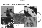
- Optical Microscopy shown in Figure 1 , shows a progression from wetcake to rotor shearing 8 cycles shearing with a high shear rate mixer.
- R/S performs the initial breakup of the bundles and this is significantly furthered by passing through a shearing device.
- the experimental results described throughout are expected to be obtainable using multiple shearing devices including those described in Table 3 as well as HAAKE TM mixers, Brabender mixers, Omni mixers, Silverson mixers, Gaullin homogenizers, and/or twin-screw extruders and/or the Netzch Omega ® Economic Dispersionionizer and/or the Sonolator from Sonic Corp.
- OCSiAl source TUBALL TM single wall carbon nanotubes. Batch number 01RW01.N1.257 production date: 20.12.2016.
- Sample 180418-MF-1 Measured 0.34% solids (17 g sample size) ⁇ 500 g sample recovered.
- the oxidized and non-oxidized OCSiAl cells were formed into Li ion battery single layer pouch cells - cell details below: NCM523 Cathode//Anode
- Figure 2 shows a comparison of a control vs. OcSiAl Tuball TM Batt product (PVP dispersion) vs. the effect of oxidation and processing (shearing, sonication, etc.).
- the control shows very low cycle life. End of cycle life in the industry is generally regarded as the point at which the capacity has faded to 80% of the original capacity - i.e., the cell can now only be charged to 80% of its initial capacity - it will not accept any more charge.
- the major culprit is loss of electrical connectivity is due to cracking of the silicon particles which swell upon charging (they get loaded with Lithium from the cathode) and discharging (Li moves back to the cathode). When they swell they push the graphite particles closer together but these do not move back upon de-swell resulting in gaps and particles that are now electrically isolated.
- FIG. 3 shows Optical Microscopy (all images at - same magnification).
- the center electron micrograph shows the "as received" OCSiAl dry powder. It is a ribbon or tree trunk type structure with a very small amount of fibrillation and low surface area. In this structure the majority of the tubes surface area is not exposed as it is protected by surrounding tubes.
- the top left image shows effect of putting a dilute (-0.15%) solution in water through a rotor/stator at 9900 rpm for 10 minutes. Clearly this process has some effect on breaking up the ribbons and causing some level of fibrillation thus increasing the surface area (SA).
- the bottom left image of Figure 3 shows effect of putting the above material through a shear treatment - further increasing the fibrillation and thus increasing the exposed surface area.
- Top right shows oxidized OCSiAl through the shearing treatment - again increasing the fibrillation and thus surface area. Oxidation introduces functionality to the material and significantly reduces the amount of residual metal contamination.
- Bottom right shows the effect of adding surfactant to the oxidized sheared material followed by sonication. Sonication resulted in further increase in fibrillation and surface area.
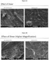
- Figures 4A and 4B electron micrographs show side by side comparisons of unoxidized vs. oxidized shear treated OCSiAl.
- Figure 4A shows 2,500X magnification while Figure 4B shows 25,000X magnification. Both levels of magnification show significantly more fibrillation for the oxidized vs. non-oxidized sheared materials.
- Figure 5 shows a comparison of dry powder OCSiAl vs. PSS (polystyrene sulfonate) dispersion of oxidized OCSiAl
- Figure 6 shows that it is possible to get the ribbons defibrillated down to single tubes in some instances.
- Figure 7 an electron micrograph, shows oxidized carbon nanotubes and O-OCSiAl mixed and put through a shearing treatment together to make intimate Molecular Rebar ® (MR) mixture.
- This micrograph shows a synergy in that the MR forms a coating on the SiOx particles and interacts intimately with the carbon black while the "tree trunk" Ox-OCSiAl MR is long enough to span the length of the SiOx particle and is long enough to span the gaps that are too large for MR to bridge.
- Figure 7 shows the tree trunk covering the entire length of the SiOx particle. Such lengths are easily capable of spanning the gaps between SiOx and graphite.
- MR particles may be too short to accomplish this but, as shown in Figure 7 , MR particles cover the surface of the SiOx in a "cage type" structure.
- the oxidized OCSiAl structures are capable of having electroactive material, e.g. Li attached to the functional groups.
- Electroactive materials include, but are not limited to, graphite, lithium cobalt oxide, lithium iron phosphate, and/or lithium manganese oxide.
- Table 4 Sample 4.12 N load 2.16 N Load Reading ( ⁇ ) Ave ( ⁇ ) SEM ( ⁇ ) Reading ( ⁇ ) Ave ( ⁇ ) SEM ( ⁇ ) Bare Cu plates 0.0048 0.0054 0.0006 0.0106 0.0139 0.0017 0.0066 0.0154 0.0048 0.0157 Cu with 2 sided C coat 0.971 1.083 0.172 2.315 2.045 0.188 1.420 2.138 0.857 1.683 Cu with 1 sided C coat 0.792 0.822 0.025 0.945 1.064 0.060 0.872 1.106 0.803 1.140 Cu foil (no C coat) 0.272 0.478 0.128 0.808 0.879 0.042 0.450 0.874 0.712 0.954 Si080-1 non-Calendered 1.786 1.493 0.149 2.141 1.865 0.149 1.296 1.63 1.398 1.824 Calendered 0.728 0.669 0.025 0.816 0.8
- High purity OCSiAl SWCNT was determined by TGA analysis to have 1.3% oxidation level and 0.6% residuals (metallic impurities) compared to low purity OCSiAl SWCNT which has 0.6% oxidation level and 17.7% Residuals as received.
- a sample of 2.8 g of high purity OCSiAl SWCNT was diluted with deionized water to 650 g total (0.43% solids) and subjected to 10 minutes of processing using a Rotor Stator. This material was then subjected to shearing force at 1.37.10 7 Pa (2000 psi) for a single pass through the device. The pressure was increased to 5.51.10 7 Pa (8000 psi) and passed through the shear device an additional 8 times.
- Example 8 Aqueous dispersion of high purity OCSiAl Tuball SWCNT and Sodium Carboxymethyl Cellulose
- a total of 2 grams of high purity OCSiAl Tuball SWCNT was diluted to 0.4% solids with deionized water.
- the mixture was subjected to Rotor Stator processing for 5 minutes at 10,000 rpm.
- the sample was diluted to 0.2% and sheared for 2 passes through the shearing device at 5.86.10 7 -6.20.10 7 Pa (8500-9000 psi).
- 105 grams of 3.79% solids Walocel CRT 30 PA sodium carboxymethylcellulose (CMC) in deionized water was added.
- the mixture was then passed through the shearing device for another 8 passes while keeping the temperature of the mixture below 40°C.
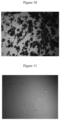
- Figures 10-11 Optical microscopy of the SWCNT through the Rotor Stator compared to the final dispersion are shown in Figures 10-11.
- Figure 10 shows high purity OCSiAl Tuball SWCNT before shearing
- Figure 11 shows high purity OCSiAl Tuball SWCNT after shearing device and addition of CMC. Both are at 11.25X magnification.
- the lack of any apparent particles in the optical image after dispersion means the fibrils are less than 1 millimeter in size (scale bar is 1 millimeter.).
- Example 9 Aqueous dispersion of oxidized Zeonano SWCNT and Sodium Carboxymethyl Cellulose
- An aqueous mixture of 0.77% oxidized Zeonano SWCNT in deionized water was processed using a Rotor Stator for 25 minutes at 10,000 rpm. The oxidation was previously described. The mixture was maintained at 27-31°C during processing. The material was diluted to 0.17% solids. The mixture was passed through a shear device 5 times. The first pass was sheared at 4.13.10 7 Pa (6000 psi) and the subsequent passes at 5.51.10 7 -6.20.107 Pa (8000-9000 psi). The pH was adjusted to pH 7 after pass 4. After pass 5, Walocel CRT 30 PA sodium carboxymethyl cellulose (CMC) was added in a mass ratio of 1 SWCNT to 1 CMC.
- CMC carboxymethyl cellulose
- Example 10 Aqueous dispersion of un-oxidized Zeonano SWCNT and Sodium Carboxymethyl Cellulose
- a concentration of 0.3% high purity OCSiAl was added to cyrene and sonicated in a sonic bath for 150 minutes to create a dispersion of SWCNT in cyrene.
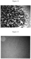
- Figure 16 shows High purity OCSiAl SWCNT after 30 minutes sonication (169X magnification).
- Figure 17 shows High purity OCSiAl SWCNT after 150 minutes sonication (169X magnification).
Landscapes
- Chemical & Material Sciences (AREA)
- Chemical Kinetics & Catalysis (AREA)
- General Chemical & Material Sciences (AREA)
- Electrochemistry (AREA)
- Organic Chemistry (AREA)
- Engineering & Computer Science (AREA)
- Materials Engineering (AREA)
- Nanotechnology (AREA)
- Inorganic Chemistry (AREA)
- Health & Medical Sciences (AREA)
- Medicinal Chemistry (AREA)
- Polymers & Plastics (AREA)
- Composite Materials (AREA)
- Carbon And Carbon Compounds (AREA)
- Battery Electrode And Active Subsutance (AREA)
- Cell Separators (AREA)
- Manufacturing & Machinery (AREA)
- Electric Double-Layer Capacitors Or The Like (AREA)
Applications Claiming Priority (2)
| Application Number | Priority Date | Filing Date | Title |
|---|---|---|---|
| US201862674874P | 2018-05-22 | 2018-05-22 | |
| PCT/US2019/033764 WO2019226902A1 (en) | 2018-05-22 | 2019-05-23 | Improved lithium ion battery using high surface area nanotubes |
Publications (2)
| Publication Number | Publication Date |
|---|---|
| EP3797088A1 EP3797088A1 (en) | 2021-03-31 |
| EP3797088B1 true EP3797088B1 (en) | 2024-08-21 |
Family
ID=67211804
Family Applications (1)
| Application Number | Title | Priority Date | Filing Date |
|---|---|---|---|
| EP19737276.6A Active EP3797088B1 (en) | 2018-05-22 | 2019-05-23 | Improved lithium ion battery using high surface area nanotubes |
Country Status (5)
| Country | Link |
|---|---|
| EP (1) | EP3797088B1 (https=) |
| JP (2) | JP7759727B2 (https=) |
| KR (2) | KR20250117735A (https=) |
| CN (1) | CN112533867A (https=) |
| WO (1) | WO2019226902A1 (https=) |
Families Citing this family (7)
| Publication number | Priority date | Publication date | Assignee | Title |
|---|---|---|---|---|
| EP3660086A1 (en) * | 2018-11-30 | 2020-06-03 | SABIC Global Technologies B.V. | Polymer compositions including functionalized carbon nanotubes and exhibiting reduced sloughing |
| US20220416225A1 (en) * | 2019-11-29 | 2022-12-29 | Sanyo Electric Co., Ltd. | Electrode plate for non-aqueous electrolyte secondary battery, and non-aqueous electrolyte secondary battery |
| ES2937882B2 (es) * | 2020-09-01 | 2024-11-12 | Cabot Corp | Aceptación de carga dinámica en baterías de plomo y ácido |
| JP7833656B2 (ja) * | 2020-12-23 | 2026-03-23 | パナソニックIpマネジメント株式会社 | 電極スラリー用カーボンナノチューブ分散液、負極スラリー、非水電解質二次電池、及び、電極スラリー用カーボンナノチューブ分散液の製造方法 |
| CN116569354A (zh) * | 2020-12-23 | 2023-08-08 | 松下知识产权经营株式会社 | 电极浆料用碳纳米管分散液、负极浆料、非水电解质二次电池、以及电极浆料用碳纳米管分散液的制造方法 |
| JP7473584B2 (ja) * | 2022-04-20 | 2024-04-23 | プライムプラネットエナジー&ソリューションズ株式会社 | 正極板の製造方法 |
| EP4447147A4 (en) * | 2022-10-21 | 2025-05-21 | LG Energy Solution, Ltd. | NEGATIVE ELECTRODE COMPOSITION, NEGATIVE ELECTRODE FOR LITHIUM SECONDARY BATTERY COMPRISING SAME, AND LITHIUM SECONDARY BATTERY COMPRISING A NEGATIVE ELECTRODE |
Family Cites Families (14)
| Publication number | Priority date | Publication date | Assignee | Title |
|---|---|---|---|---|
| US756953A (en) | 1902-09-30 | 1904-04-12 | Auguste Gaulin | System for intimately mixing milk. |
| ES2957854T3 (es) | 2008-12-18 | 2024-01-26 | Molecular Rebar Design Llc | Nanotubos de carbono exfoliados, métodos para la producción de los mismos y productos obtenidos de estos |
| CN104192818A (zh) * | 2008-12-30 | 2014-12-10 | 独立行政法人产业技术综合研究所 | 取向单层碳纳米管集合体、块状取向单层碳纳米管集合体、粉体状取向单层碳纳米管集合体、及其制造方法 |
| WO2011163129A2 (en) * | 2010-06-22 | 2011-12-29 | Designed Nanotubes, LLC | Modified carbon nanotubes, methods for production thereof and products obtained therefrom |
| JP6004198B2 (ja) * | 2011-05-25 | 2016-10-05 | パナソニックIpマネジメント株式会社 | 電極、その製造方法、それを含むエネルギーデバイス、電子機器および輸送デバイス |
| JP6088500B2 (ja) * | 2011-06-23 | 2017-03-01 | モレキュラー レバー デザイン,エルエルシー | 離散的カーボンナノチューブを含有する鉛酸バッテリー配合物 |
| US8808909B2 (en) * | 2011-06-23 | 2014-08-19 | Melecular Rebar Design, LLC | Lithium ion batteries using discrete carbon nanotubes, methods for production thereof and products obtained therefrom |
| KR20140069014A (ko) * | 2011-09-06 | 2014-06-09 | 사우스웨스트 나노테크놀로지스, 인크. | 단일벽 탄소 나노튜브 정제 방법 및 개선된 단일벽 탄소 나노튜브 |
| AU2013278063B2 (en) * | 2012-06-21 | 2016-07-07 | Molecular Rebar Design, Llc | Binders, electrolytes and separator films for energy storage and collection devices using discrete carbon nanotubes |
| EP3052442B1 (en) * | 2013-09-30 | 2020-02-12 | Molecular Rebar Design, LLC | High carbon nanotube content fluids |
| EP3107581A1 (en) * | 2014-02-21 | 2016-12-28 | Molecular Rebar Design LLC | Payload molecule delivery using functionalized discrete carbon nanotubes |
| KR102305509B1 (ko) * | 2014-07-22 | 2021-09-28 | 씨-나노 테크놀로지 리미티드 | 배터리용 전극 조성물 |
| JP2016054113A (ja) * | 2014-09-04 | 2016-04-14 | 日本ゼオン株式会社 | 二次電池電極用複合体の製造方法、二次電池電極用複合体、二次電池用電極および二次電池 |
| WO2017177176A1 (en) * | 2016-04-07 | 2017-10-12 | Molecular Rebar Design, Llc | Nanotube mediation of degradative chemicals for oil-field applications |
-
2019
- 2019-05-23 JP JP2020564914A patent/JP7759727B2/ja active Active
- 2019-05-23 EP EP19737276.6A patent/EP3797088B1/en active Active
- 2019-05-23 CN CN201980049039.3A patent/CN112533867A/zh active Pending
- 2019-05-23 KR KR1020257025136A patent/KR20250117735A/ko active Pending
- 2019-05-23 WO PCT/US2019/033764 patent/WO2019226902A1/en not_active Ceased
- 2019-05-23 KR KR1020207036421A patent/KR20210158747A/ko not_active Ceased
-
2025
- 2025-02-21 JP JP2025026481A patent/JP2025087733A/ja active Pending
Non-Patent Citations (1)
| Title |
|---|
| F. PICO ET AL: "Single-Walled Carbon Nanotubes as Electrodes in Supercapacitors", JOURNAL OF THE ELECTROCHEMICAL SOCIETY, vol. 151, no. 6, 1 January 2004 (2004-01-01), pages A831, XP055679715, ISSN: 0013-4651, DOI: 10.1149/1.1738678 * |
Also Published As
| Publication number | Publication date |
|---|---|
| WO2019226902A1 (en) | 2019-11-28 |
| JP2021527295A (ja) | 2021-10-11 |
| JP2025087733A (ja) | 2025-06-10 |
| KR20250117735A (ko) | 2025-08-05 |
| KR20210158747A (ko) | 2021-12-31 |
| CN112533867A (zh) | 2021-03-19 |
| JP7759727B2 (ja) | 2025-10-24 |
| EP3797088A1 (en) | 2021-03-31 |
Similar Documents
| Publication | Publication Date | Title |
|---|---|---|
| US12583750B2 (en) | Lithium ion battery using high surface area nanotubes | |
| EP3797088B1 (en) | Improved lithium ion battery using high surface area nanotubes | |
| US20250320368A1 (en) | Dispersions comprising individualized carbon nanotubes | |
| US10608282B2 (en) | Binders, electrolytes and separator films for energy storage and collection devices using discrete carbon nanotubes | |
| US12162758B2 (en) | Lithium ion battery using high surface area nanotubes | |
| Wang et al. | Fabrication of high‐performance flexible alkaline batteries by implementing multiwalled carbon nanotubes and copolymer separator | |
| US9912009B2 (en) | Binders, electrolytes and separator films for energy storage and collection devices using discrete carbon nanotubes | |
| CN106029564B (zh) | 高碳纳米管含量流体 | |
| US20200313162A1 (en) | Method of producing graphene-encapsulated graphite-supported anode active material for lithium-ion batteries | |
| US20200313170A1 (en) | Graphene-encapsulated graphite-supported anode active material for lithium-ion batteries | |
| Okafor et al. | Surface modification of carbon nanotubes and their nanocomposites for fuel cell applications: A review. | |
| EP3780157A1 (en) | Energy storage device electrode and energy storage device | |
| WO2022183049A1 (en) | Dispersions comprising high surface area nanotubes and discrete carbon nanotubes | |
| KR20260043227A (ko) | 전극 제조 방법, 이에 의해 제조된 전극, 및 이를 포함하는 리튬 이차 전지 | |
| BR112014032138B1 (pt) | Composição de uma bateria ou célula eletrolítica para uso como um material ligante, um material eletrolítico ou um material de película de separação de um dispositivo de armazenamento ou coleta de energia |
Legal Events
| Date | Code | Title | Description |
|---|---|---|---|
| STAA | Information on the status of an ep patent application or granted ep patent |
Free format text: STATUS: UNKNOWN |
|
| STAA | Information on the status of an ep patent application or granted ep patent |
Free format text: STATUS: THE INTERNATIONAL PUBLICATION HAS BEEN MADE |
|
| PUAI | Public reference made under article 153(3) epc to a published international application that has entered the european phase |
Free format text: ORIGINAL CODE: 0009012 |
|
| STAA | Information on the status of an ep patent application or granted ep patent |
Free format text: STATUS: REQUEST FOR EXAMINATION WAS MADE |
|
| 17P | Request for examination filed |
Effective date: 20201214 |
|
| AK | Designated contracting states |
Kind code of ref document: A1 Designated state(s): AL AT BE BG CH CY CZ DE DK EE ES FI FR GB GR HR HU IE IS IT LI LT LU LV MC MK MT NL NO PL PT RO RS SE SI SK SM TR |
|
| AX | Request for extension of the european patent |
Extension state: BA ME |
|
| DAV | Request for validation of the european patent (deleted) | ||
| DAX | Request for extension of the european patent (deleted) | ||
| STAA | Information on the status of an ep patent application or granted ep patent |
Free format text: STATUS: EXAMINATION IS IN PROGRESS |
|
| 17Q | First examination report despatched |
Effective date: 20231220 |
|
| GRAP | Despatch of communication of intention to grant a patent |
Free format text: ORIGINAL CODE: EPIDOSNIGR1 |
|
| STAA | Information on the status of an ep patent application or granted ep patent |
Free format text: STATUS: GRANT OF PATENT IS INTENDED |
|
| RIC1 | Information provided on ipc code assigned before grant |
Ipc: H01M 50/44 20210101ALI20240227BHEP Ipc: H01M 50/431 20210101ALI20240227BHEP Ipc: H01M 10/30 20060101ALI20240227BHEP Ipc: H01M 10/06 20060101ALI20240227BHEP Ipc: H01M 10/0525 20100101ALI20240227BHEP Ipc: H01M 6/16 20060101ALI20240227BHEP Ipc: C01B 32/174 20170101ALI20240227BHEP Ipc: C01B 32/159 20170101ALI20240227BHEP Ipc: C01B 32/17 20170101ALI20240227BHEP Ipc: H01M 4/62 20060101ALI20240227BHEP Ipc: C08K 3/04 20060101ALI20240227BHEP Ipc: C01B 32/158 20170101AFI20240227BHEP |
|
| INTG | Intention to grant announced |
Effective date: 20240327 |
|
| RIN1 | Information on inventor provided before grant (corrected) |
Inventor name: COLE, EMILY BARTON Inventor name: HENDERSON, NANCY Inventor name: BHAT, VINAY Inventor name: GAZDA, JERZY Inventor name: BOSNYAK, CLIVE P. Inventor name: FINLAYSON, MALCOLM FRANCIS |
|
| GRAS | Grant fee paid |
Free format text: ORIGINAL CODE: EPIDOSNIGR3 |
|
| GRAA | (expected) grant |
Free format text: ORIGINAL CODE: 0009210 |
|
| STAA | Information on the status of an ep patent application or granted ep patent |
Free format text: STATUS: THE PATENT HAS BEEN GRANTED |
|
| AK | Designated contracting states |
Kind code of ref document: B1 Designated state(s): AL AT BE BG CH CY CZ DE DK EE ES FI FR GB GR HR HU IE IS IT LI LT LU LV MC MK MT NL NO PL PT RO RS SE SI SK SM TR |
|
| REG | Reference to a national code |
Ref country code: GB Ref legal event code: FG4D |
|
| REG | Reference to a national code |
Ref country code: CH Ref legal event code: EP |
|
| REG | Reference to a national code |
Ref country code: IE Ref legal event code: FG4D |
|
| REG | Reference to a national code |
Ref country code: DE Ref legal event code: R096 Ref document number: 602019057393 Country of ref document: DE |
|
| REG | Reference to a national code |
Ref country code: LT Ref legal event code: MG9D |
|
| REG | Reference to a national code |
Ref country code: NL Ref legal event code: MP Effective date: 20240821 |
|
| PG25 | Lapsed in a contracting state [announced via postgrant information from national office to epo] |
Ref country code: NO Free format text: LAPSE BECAUSE OF FAILURE TO SUBMIT A TRANSLATION OF THE DESCRIPTION OR TO PAY THE FEE WITHIN THE PRESCRIBED TIME-LIMIT Effective date: 20241121 |
|
| REG | Reference to a national code |
Ref country code: AT Ref legal event code: MK05 Ref document number: 1715355 Country of ref document: AT Kind code of ref document: T Effective date: 20240821 |
|
| PG25 | Lapsed in a contracting state [announced via postgrant information from national office to epo] |
Ref country code: NL Free format text: LAPSE BECAUSE OF FAILURE TO SUBMIT A TRANSLATION OF THE DESCRIPTION OR TO PAY THE FEE WITHIN THE PRESCRIBED TIME-LIMIT Effective date: 20240821 Ref country code: FI Free format text: LAPSE BECAUSE OF FAILURE TO SUBMIT A TRANSLATION OF THE DESCRIPTION OR TO PAY THE FEE WITHIN THE PRESCRIBED TIME-LIMIT Effective date: 20240821 Ref country code: PL Free format text: LAPSE BECAUSE OF FAILURE TO SUBMIT A TRANSLATION OF THE DESCRIPTION OR TO PAY THE FEE WITHIN THE PRESCRIBED TIME-LIMIT Effective date: 20240821 Ref country code: GR Free format text: LAPSE BECAUSE OF FAILURE TO SUBMIT A TRANSLATION OF THE DESCRIPTION OR TO PAY THE FEE WITHIN THE PRESCRIBED TIME-LIMIT Effective date: 20241122 Ref country code: PT Free format text: LAPSE BECAUSE OF FAILURE TO SUBMIT A TRANSLATION OF THE DESCRIPTION OR TO PAY THE FEE WITHIN THE PRESCRIBED TIME-LIMIT Effective date: 20241223 |
|
| PG25 | Lapsed in a contracting state [announced via postgrant information from national office to epo] |
Ref country code: BG Free format text: LAPSE BECAUSE OF FAILURE TO SUBMIT A TRANSLATION OF THE DESCRIPTION OR TO PAY THE FEE WITHIN THE PRESCRIBED TIME-LIMIT Effective date: 20240821 |
|
| PG25 | Lapsed in a contracting state [announced via postgrant information from national office to epo] |
Ref country code: LV Free format text: LAPSE BECAUSE OF FAILURE TO SUBMIT A TRANSLATION OF THE DESCRIPTION OR TO PAY THE FEE WITHIN THE PRESCRIBED TIME-LIMIT Effective date: 20240821 |
|
| PG25 | Lapsed in a contracting state [announced via postgrant information from national office to epo] |
Ref country code: IS Free format text: LAPSE BECAUSE OF FAILURE TO SUBMIT A TRANSLATION OF THE DESCRIPTION OR TO PAY THE FEE WITHIN THE PRESCRIBED TIME-LIMIT Effective date: 20241221 Ref country code: AT Free format text: LAPSE BECAUSE OF FAILURE TO SUBMIT A TRANSLATION OF THE DESCRIPTION OR TO PAY THE FEE WITHIN THE PRESCRIBED TIME-LIMIT Effective date: 20240821 |
|
| PG25 | Lapsed in a contracting state [announced via postgrant information from national office to epo] |
Ref country code: HR Free format text: LAPSE BECAUSE OF FAILURE TO SUBMIT A TRANSLATION OF THE DESCRIPTION OR TO PAY THE FEE WITHIN THE PRESCRIBED TIME-LIMIT Effective date: 20240821 |
|
| PG25 | Lapsed in a contracting state [announced via postgrant information from national office to epo] |
Ref country code: RS Free format text: LAPSE BECAUSE OF FAILURE TO SUBMIT A TRANSLATION OF THE DESCRIPTION OR TO PAY THE FEE WITHIN THE PRESCRIBED TIME-LIMIT Effective date: 20241121 Ref country code: ES Free format text: LAPSE BECAUSE OF FAILURE TO SUBMIT A TRANSLATION OF THE DESCRIPTION OR TO PAY THE FEE WITHIN THE PRESCRIBED TIME-LIMIT Effective date: 20240821 |
|
| PG25 | Lapsed in a contracting state [announced via postgrant information from national office to epo] |
Ref country code: RS Free format text: LAPSE BECAUSE OF FAILURE TO SUBMIT A TRANSLATION OF THE DESCRIPTION OR TO PAY THE FEE WITHIN THE PRESCRIBED TIME-LIMIT Effective date: 20241121 Ref country code: PT Free format text: LAPSE BECAUSE OF FAILURE TO SUBMIT A TRANSLATION OF THE DESCRIPTION OR TO PAY THE FEE WITHIN THE PRESCRIBED TIME-LIMIT Effective date: 20241223 Ref country code: PL Free format text: LAPSE BECAUSE OF FAILURE TO SUBMIT A TRANSLATION OF THE DESCRIPTION OR TO PAY THE FEE WITHIN THE PRESCRIBED TIME-LIMIT Effective date: 20240821 Ref country code: NO Free format text: LAPSE BECAUSE OF FAILURE TO SUBMIT A TRANSLATION OF THE DESCRIPTION OR TO PAY THE FEE WITHIN THE PRESCRIBED TIME-LIMIT Effective date: 20241121 Ref country code: NL Free format text: LAPSE BECAUSE OF FAILURE TO SUBMIT A TRANSLATION OF THE DESCRIPTION OR TO PAY THE FEE WITHIN THE PRESCRIBED TIME-LIMIT Effective date: 20240821 Ref country code: LV Free format text: LAPSE BECAUSE OF FAILURE TO SUBMIT A TRANSLATION OF THE DESCRIPTION OR TO PAY THE FEE WITHIN THE PRESCRIBED TIME-LIMIT Effective date: 20240821 Ref country code: IS Free format text: LAPSE BECAUSE OF FAILURE TO SUBMIT A TRANSLATION OF THE DESCRIPTION OR TO PAY THE FEE WITHIN THE PRESCRIBED TIME-LIMIT Effective date: 20241221 Ref country code: HR Free format text: LAPSE BECAUSE OF FAILURE TO SUBMIT A TRANSLATION OF THE DESCRIPTION OR TO PAY THE FEE WITHIN THE PRESCRIBED TIME-LIMIT Effective date: 20240821 Ref country code: GR Free format text: LAPSE BECAUSE OF FAILURE TO SUBMIT A TRANSLATION OF THE DESCRIPTION OR TO PAY THE FEE WITHIN THE PRESCRIBED TIME-LIMIT Effective date: 20241122 Ref country code: FI Free format text: LAPSE BECAUSE OF FAILURE TO SUBMIT A TRANSLATION OF THE DESCRIPTION OR TO PAY THE FEE WITHIN THE PRESCRIBED TIME-LIMIT Effective date: 20240821 Ref country code: ES Free format text: LAPSE BECAUSE OF FAILURE TO SUBMIT A TRANSLATION OF THE DESCRIPTION OR TO PAY THE FEE WITHIN THE PRESCRIBED TIME-LIMIT Effective date: 20240821 Ref country code: BG Free format text: LAPSE BECAUSE OF FAILURE TO SUBMIT A TRANSLATION OF THE DESCRIPTION OR TO PAY THE FEE WITHIN THE PRESCRIBED TIME-LIMIT Effective date: 20240821 Ref country code: AT Free format text: LAPSE BECAUSE OF FAILURE TO SUBMIT A TRANSLATION OF THE DESCRIPTION OR TO PAY THE FEE WITHIN THE PRESCRIBED TIME-LIMIT Effective date: 20240821 |
|
| PG25 | Lapsed in a contracting state [announced via postgrant information from national office to epo] |
Ref country code: RO Free format text: LAPSE BECAUSE OF FAILURE TO SUBMIT A TRANSLATION OF THE DESCRIPTION OR TO PAY THE FEE WITHIN THE PRESCRIBED TIME-LIMIT Effective date: 20240821 Ref country code: SM Free format text: LAPSE BECAUSE OF FAILURE TO SUBMIT A TRANSLATION OF THE DESCRIPTION OR TO PAY THE FEE WITHIN THE PRESCRIBED TIME-LIMIT Effective date: 20240821 Ref country code: DK Free format text: LAPSE BECAUSE OF FAILURE TO SUBMIT A TRANSLATION OF THE DESCRIPTION OR TO PAY THE FEE WITHIN THE PRESCRIBED TIME-LIMIT Effective date: 20240821 |
|
| PG25 | Lapsed in a contracting state [announced via postgrant information from national office to epo] |
Ref country code: EE Free format text: LAPSE BECAUSE OF FAILURE TO SUBMIT A TRANSLATION OF THE DESCRIPTION OR TO PAY THE FEE WITHIN THE PRESCRIBED TIME-LIMIT Effective date: 20240821 |
|
| PG25 | Lapsed in a contracting state [announced via postgrant information from national office to epo] |
Ref country code: CZ Free format text: LAPSE BECAUSE OF FAILURE TO SUBMIT A TRANSLATION OF THE DESCRIPTION OR TO PAY THE FEE WITHIN THE PRESCRIBED TIME-LIMIT Effective date: 20240821 |
|
| PG25 | Lapsed in a contracting state [announced via postgrant information from national office to epo] |
Ref country code: SK Free format text: LAPSE BECAUSE OF FAILURE TO SUBMIT A TRANSLATION OF THE DESCRIPTION OR TO PAY THE FEE WITHIN THE PRESCRIBED TIME-LIMIT Effective date: 20240821 |
|
| REG | Reference to a national code |
Ref country code: DE Ref legal event code: R097 Ref document number: 602019057393 Country of ref document: DE |
|
| PLBE | No opposition filed within time limit |
Free format text: ORIGINAL CODE: 0009261 |
|
| STAA | Information on the status of an ep patent application or granted ep patent |
Free format text: STATUS: NO OPPOSITION FILED WITHIN TIME LIMIT |
|
| PGFP | Annual fee paid to national office [announced via postgrant information from national office to epo] |
Ref country code: DE Payment date: 20250325 Year of fee payment: 7 |
|
| PGFP | Annual fee paid to national office [announced via postgrant information from national office to epo] |
Ref country code: IT Payment date: 20250422 Year of fee payment: 7 |
|
| PGFP | Annual fee paid to national office [announced via postgrant information from national office to epo] |
Ref country code: FR Payment date: 20250401 Year of fee payment: 7 |
|
| 26N | No opposition filed |
Effective date: 20250522 |
|
| PG25 | Lapsed in a contracting state [announced via postgrant information from national office to epo] |
Ref country code: SE Free format text: LAPSE BECAUSE OF FAILURE TO SUBMIT A TRANSLATION OF THE DESCRIPTION OR TO PAY THE FEE WITHIN THE PRESCRIBED TIME-LIMIT Effective date: 20240821 |
|
| REG | Reference to a national code |
Ref country code: CH Ref legal event code: H13 Free format text: ST27 STATUS EVENT CODE: U-0-0-H10-H13 (AS PROVIDED BY THE NATIONAL OFFICE) Effective date: 20251223 |
|
| PG25 | Lapsed in a contracting state [announced via postgrant information from national office to epo] |
Ref country code: LU Free format text: LAPSE BECAUSE OF NON-PAYMENT OF DUE FEES Effective date: 20250523 |
|
| PG25 | Lapsed in a contracting state [announced via postgrant information from national office to epo] |
Ref country code: CH Free format text: LAPSE BECAUSE OF NON-PAYMENT OF DUE FEES Effective date: 20250531 |
|
| REG | Reference to a national code |
Ref country code: BE Ref legal event code: MM Effective date: 20250531 |
|
| PG25 | Lapsed in a contracting state [announced via postgrant information from national office to epo] |
Ref country code: MC Free format text: LAPSE BECAUSE OF FAILURE TO SUBMIT A TRANSLATION OF THE DESCRIPTION OR TO PAY THE FEE WITHIN THE PRESCRIBED TIME-LIMIT Effective date: 20240821 |
|
| PGFP | Annual fee paid to national office [announced via postgrant information from national office to epo] |
Ref country code: GB Payment date: 20260313 Year of fee payment: 8 |
|
| PG25 | Lapsed in a contracting state [announced via postgrant information from national office to epo] |
Ref country code: IE Free format text: LAPSE BECAUSE OF NON-PAYMENT OF DUE FEES Effective date: 20250523 |
|
| PG25 | Lapsed in a contracting state [announced via postgrant information from national office to epo] |
Ref country code: BE Free format text: LAPSE BECAUSE OF NON-PAYMENT OF DUE FEES Effective date: 20250531 |