EP3796346B1 - Ausgleichsblock für luftdrosselspulen - Google Patents
Ausgleichsblock für luftdrosselspulen Download PDFInfo
- Publication number
- EP3796346B1 EP3796346B1 EP19198956.5A EP19198956A EP3796346B1 EP 3796346 B1 EP3796346 B1 EP 3796346B1 EP 19198956 A EP19198956 A EP 19198956A EP 3796346 B1 EP3796346 B1 EP 3796346B1
- Authority
- EP
- European Patent Office
- Prior art keywords
- compensation block
- block
- air
- compensation
- spider arm
- Prior art date
- Legal status (The legal status is an assumption and is not a legal conclusion. Google has not performed a legal analysis and makes no representation as to the accuracy of the status listed.)
- Active
Links
Images

Classifications
-
- H—ELECTRICITY
- H01—ELECTRIC ELEMENTS
- H01F—MAGNETS; INDUCTANCES; TRANSFORMERS; SELECTION OF MATERIALS FOR THEIR MAGNETIC PROPERTIES
- H01F27/00—Details of transformers or inductances, in general
- H01F27/28—Coils; Windings; Conductive connections
- H01F27/32—Insulating of coils, windings, or parts thereof
- H01F27/324—Insulation between coil and core, between different winding sections, around the coil; Other insulation structures
-
- H—ELECTRICITY
- H01—ELECTRIC ELEMENTS
- H01F—MAGNETS; INDUCTANCES; TRANSFORMERS; SELECTION OF MATERIALS FOR THEIR MAGNETIC PROPERTIES
- H01F37/00—Fixed inductances not covered by group H01F17/00
- H01F37/005—Fixed inductances not covered by group H01F17/00 without magnetic core
-
- H—ELECTRICITY
- H01—ELECTRIC ELEMENTS
- H01F—MAGNETS; INDUCTANCES; TRANSFORMERS; SELECTION OF MATERIALS FOR THEIR MAGNETIC PROPERTIES
- H01F27/00—Details of transformers or inductances, in general
- H01F27/28—Coils; Windings; Conductive connections
- H01F27/30—Fastening or clamping coils, windings, or parts thereof together; Fastening or mounting coils or windings on core, casing, or other support
- H01F27/306—Fastening or mounting coils or windings on core, casing or other support
Definitions
- the invention relates to a compensation block for air choke coils, wherein the compensation block comprises a sandwich structure with an upper insulating block, a lower insulating block and an elastomer block located therebetween.
- the invention further relates to a method for assembling such a compensation block and to an air choke coil with such a compensation block.
- Such a compensation block is from the EN 10 2008 010548 A1
- the compensation block shown there has a sandwich-like structure.
- the DE 201 05 608 U1 describes an air choke coil that is also equipped with a compensation block.
- the compensation block is arranged between a star arm and the air choke coil.
- Dry-insulated air reactors are used, for example, in electrical systems for energy transmission and in power supply systems of industrial plants to protect these systems or to increase their performance.
- current limiting chokes are used to limit short-circuit currents in areas of power grids which, due to their low network impedance, have very high short-circuit currents in the event of a fault, such as in substations in the area of multiple-fed busbars.
- the task of the current limiting chokes connected in series is to limit the short-circuit power in power grids by means of the additional impedance introduced so that circuit breakers can safely interrupt the short-circuit current in the event of a fault.
- a typical air choke coil as used in the WO 2009/126977 has concentric winding layers which are held at their upper and lower axial ends by a holding star which is composed of several arms arranged radially in a star shape, so-called star leaves.
- a large number of individual star blades can be used, which are only located in the area below and above the winding layers in order to save star blade material.
- the opposing holding stars or star blades are tensioned against each other using spacer strips or tension bandages running between the winding layers in order to hold the winding layers.
- the star blades and spacer bars are used simultaneously as winding aids by first clamping the lower star blades onto a rotating device and then building up the winding layers on top of them, with a set of spacer bars being mounted between each one.
- the invention is therefore based on the object of improving the design of air choke coils so that gap formation due to settlement can be reduced.
- the current limiting choke according to Fig.1 has concentrically arranged windings reinforced with glass fiber reinforced epoxy resin, of which only the outer winding layer is visible.
- the windings are fixed by star holders, the arms of which extend radially from the coil axis beyond the radius of the outer winding.
- a compensating block is now inserted between one winding end and an upper star arm of the air choke coil.
- this compensation block has a sandwich structure with an upper insulating block, a lower insulating block and an elastomer block in between.
- the upper star arms of the air choke coil and the compensation blocks are positively connected by means of a comb connection.
- the star arms have a rectangular recess whose width corresponds to the width of the compensation blocks and whose height corresponds to part of the height of the upper insulating block of the compensation blocks.
- the compensation blocks have a counterpart groove to accommodate the section of the star arms above the rectangular recess.
- This positive connection fixes the compensation blocks in their position and prevents them from slipping.
- the clamping device can, for example, consist of threaded pins which protrude through the sandwich structure of the compensation block and press the compensation blocks together by means of screws.
- clamping devices based on clamps, rivet connections or snap fasteners are also conceivable.
Landscapes
- Engineering & Computer Science (AREA)
- Power Engineering (AREA)
- Transformers For Measuring Instruments (AREA)
- Coils Or Transformers For Communication (AREA)
- Coils Of Transformers For General Uses (AREA)
- Insulating Of Coils (AREA)
Description
- Die Erfindung betrifft einen Ausgleichsblock für Luftdrosselspulen, wobei der Ausgleichsblock eine Sandwichstruktur mit einem oberen Isolierstoffblock, einem unteren Isolierstoffblock und einen dazwischen liegenden Elastomerblock umfasst.
- Die Erfindung betrifft ferner ein Verfahren zur Montage eines solchen Ausgleichsblocks sowie eine Luftdrosselspule mit einem solchen Ausgleichsblock.
- Ein solcher Ausgleichsblock ist aus der
DE 10 2008 010548 A1 bekannt. Der dort gezeigte Ausgleichsblock verfügt über einen sandwichartigen Aufbau. - Die
DE 201 05 608 U1 beschreibt Luftdrosselspule, die ebenfalls mit einem Ausgleichsblock ausgerüstet ist. Dabei ist der Ausgleichsblock zwischen einem Sternarm und der Luftdrosselspule angeordnet. - Weiterer Stand der Technik ist in der
WO 2009/126977 A1 , derEP O 084 412 A1 DE 29 34 719 A1 beschrieben. - Trockenisolierte Luftdrosselspulen werden beispielsweise in elektrischen Systemen zur Energieübertragung und in Stromversorgungssystemen von Industrieanlagen eingesetzt, um diese Systeme zu schützen oder um deren Leistungsfähigkeit zu erhöhen.
- Da keine Isolieröle zum Einsatz kommen, sind sie umweltfreundlich und es gibt kein erhöhtes Risiko durch Brandgefahr. Darüber hinaus sind trockenisolierte Luftdrosselspulen weitgehend wartungsfrei.
- Als Strombegrenzungsdrossel dienen sie zur Begrenzung von Kurzschlussströmen in Bereichen von Stromnetzen, welche durch ihre niedrige Netzimpedanz im Fehlerfall sehr hohe Kurzschlussströme aufweisen wie beispielsweise in Umspannwerken im Bereich von mehrfach gespeisten Sammelschienen.
- Die Aufgabe der in Reihe geschalteten Strombegrenzungsdrosseln besteht dabei darin, durch die zusätzlich eingebrachte Impedanz in Stromnetzen die Kurzschlussleistung so zu begrenzen, dass Leistungsschalter den Kurzschlussstrom im Fehlerfall sicher unterbrechen können.
- Weiterhin werden sie beispielsweise bei Hochspannungsgleichstromübertragungsanlagen als Glättungsdrosseln eingesetzt.
- Eine typische Luftdrosselspule, wie sie in der
WO 2009/126977 beschrieben ist, weist konzentrische Wicklungslagen auf, welche an ihren oberen und unteren axialen Enden jeweils von einem Haltestern gehalten werden, der sich aus mehreren sternförmig radial angeordneten Armen, sog. Sternblättern, zusammensetzt. - Anstelle eines einteiligen Haltesterns kann jeweils auch eine Vielzahl einzelner Sternblätter verwendet werden, die nur im Bereich unter und über den Wicklungslagen liegen, um Sternblattmaterial einzusparen. Die einander gegenüberliegenden Haltesterne bzw. Sternblätter werden dabei mithilfe von zwischen den Wicklungslagen verlaufenden Abstandshalteleisten oder Zugbandagen gegeneinander gespannt, um die Wicklungslagen zu halten.
- Beim Wickeln der Spule werden die Sternblätter und Abstandshalteleisten gleichzeitig als Wickelhilfen verwendet, indem zunächst die unteren Sternblätter auf einer Drehvorrichtung aufgespannt und dann darauf die Wicklungslagen aufgebaut werden, wobei dazwischen jeweils ein Satz Abstandshalteleisten montiert wird.
- Aus der
EP 2973 621 B1 ist es bekannt, zum Ausgleich unterschiedlicher Bauhöhen der einzelnen Wicklungslagen aufgrund unterschiedlicher Leiterquerschnitte einen Wicklungslagen-Steigungsausgleich vorzusehen, bei dem zwischen den einander axial gegenüberliegenden Sternblättern und der zwischenliegenden Wicklungslage Ausgleichsblätter eingelegt werden, welche die Wicklungslagen gegenüber den Sternblättern abstützen und in Axialrichtung zentrieren. - Nach dem Herstellungsvorgang und im Betrieb der Luftdrosselspulen kommt es aufgrund thermischer und mechanischer Betriebslasten zu einer Setzung der Wicklungskörper und damit zu Spaltbildungen, vor allem an den Wicklungsenden.
- Diese Spalten müssen aufwändig mit geeignetem Füllmaterial ausgeglichen werden, was im laufenden Betrieb zu vorübergehenden Abschaltungen der Anlage führt.
- Der Erfindung liegt daher die Aufgabe zugrunde, den Aufbau von Luftdrosselspulen so zu verbessern, dass Spaltbildungen durch Setzungen reduziert werden können.
- Erfindungsgemäß geschieht dies mit einer Luftdrosselspule gemäß Anspruch 1, einem Ausgleichsblock gemäß Anspruch 2 sowie einem Verfahren gemäß Anspruch 3.
- Die Erfindung wird anhand von Figuren näher erläutert.
- Es zeigen beispielhaft:
-
Fig.1 eine Strombegrenzungsdrossel mit konzentrisch angeordneten Wicklungen, die mittels glasfaserverstärktem Epoxidharz verstärkt worden sind. -
Fig.2 eine Detailansicht eines oberen Wicklungsendes mit einem erfindungsgemäßen Ausgleichsblock. -
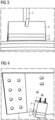
Fig.3 einen Arm eines Sternhalters mit einem erfindungsgemäßen Ausgleichsblock und -
Fig.4 einen Arm eines Sternhalters und eine Spannvorrichtung zur Komprimierung eines Ausgleichsblocks während des Montagevorgangs. - Die Strombegrenzungsdrossel gemäß
Fig.1 weist konzentrisch angeordnete, mittels glasfaserverstärktem Epoxidharz verstärkte Wicklungen auf, von denen lediglich die äußere Wicklungslage sichtbar ist. - An den oberen und unteren Enden werden die Wicklungen durch Sternhalter fixiert, deren Arme sich in radialer Richtung von der Spulenachse über den Radius der äußeren Wicklung hinaus erstrecken.
- Es wird nun zwischen ein Wicklungsende und einem oberen Sternarm der Luftdrosselspule ein Ausgleichsblock eingefügt.
- Wie aus den
Figuren 2 ,3 und 4 ersichtlich, weist dieser Ausgleichsblock eine Sandwichstruktur mit einem oberen Isolierstoffblock, einem unteren Isolierstoffblock und einen dazwischen liegenden Elastomerblock auf. - Dabei sind die oberen Sternarme der Luftdrosselspule und die Ausgleichsblöcke mittels Kammverbindung formschlüssig verbunden.
- Dazu weisen die Sternarme eine rechteckige Ausnehmung auf, deren Breite der Breite der Ausgleichsblöcke entspricht und deren Höhe einem Teil der Höhe des oberen Isolierstoffblocks der Ausgleichsblöcke entspricht.
- Die Ausgleichsblöcke weisen als Gegenstück eine Nut zur Aufnahme des Abschnitts der Sternarme oberhalb der rechteckigen Ausnehmung auf.
- Durch diese formschlüssige Verbindung werden die Ausgleichsblöcke in ihrer Lage fixiert und ein Verrutschen verhindert.
- Die Montage der Ausgleichsblöcke geschieht wie folgt:
- der Ausgleichsblock wird mittels Spannvorrichtung komprimiert;
- er wird in die vorgesehene Position zwischen einem Wicklungsende und einem oberen Sternarm der Luftdrosselspule eingefügt, die Spannvorrichtung wird gelöst.
- Die Spannvorrichtung kann beispielsweise aus Gewindestiften bestehen, welche durch die Sandwichstruktur des Ausgleichsblocks hindurchragen und mittels Schrauben die Ausgleichsblöcke zusammenpressen.
- Alternativ sind auch Spannvorrichtungen auf Basis von Klammern, Nietverbindungen oder mit Schnappverschlüssen denkbar.
-
- 1
- äußere Wicklungslage
- 2
- Arm des oberen Sternhalters
- 3
- Ausgleichsblock
- 4
- Oberer Isolierstoffblock
- 5
- Elastomerblock
- 6
- unterer Isolierstoffblock
- 7
- Spannvorrichtung
Claims (3)
- Luftdrosselspule mit einem Ausgleichsblock zwischen einem Wicklungsende und einem oberen Sternarm der Drosselspule, dadurch gekennzeichnet, dass der Aus-gleichsblock (3) eine Sandwichstruktur mit einem oberen Isolierstoffblock (4), einem unteren Isolierstoffblock (6) und einem dazwischen liegenden Elastomerblock (5) umfasst, wobei der obere Sternarm der Luftdrosselspule und der Ausgleichsblock (3) mittels Kammverbindung formschlüssig verbunden sind, wobei der Sternarm eine rechteckige Ausnehmung aufweist, deren Breite der Breite des Ausgleichsblocks entspricht und deren Höhe einem Teil der Höhe des oberen Isolierstoffblocks des Ausgleichsblocks entspricht, und der Ausgleichsblock als Gegenstück eine Nut zur Aufnahme des Abschnitts des Sternarms oberhalb der rechteckigen Ausnehmung aufweist.
- Ausgleichsblock (3) konfiguriert für eine Luftdrosselspule, der eine Sandwichstruktur mit einem oberen Isolierstoffblock (4), einem unteren Isolierstoffblock (6) und einem dazwischen liegenden Elastomerblock (5) umfasst, wobei der Ausgleichsblock (3) eine Nut aufweist, wobei der Ausgleichsblock (3) mittels Kammverbindung mit einem oberen Sternarm der Luftdrosselspule formschlüssig verbindbar ist, wobei der obere Sternarm eine rechteckige Ausnehmung aufweist, deren Breite der Breite des Ausgleichsblocks entspricht und deren Höhe einem Teil der Höhe des oberen Isolierstoffblocks des Ausgleichsblocks entspricht, so dass der Ausgleichsblock (3) zwischen einem Wicklungsende und dem oberen Sternarm (2) der Luftdrosselspule anordenbar ist und wobei die Nut zur Aufnahme des Abschnitts des Sternarms oberhalb der rechteckigen Ausnehmung ausgebildet ist.
- Verfahren zur Montage eines Ausgleichsblocks (3) in einer Luftdrosselspule nach Anspruch 1, mit folgenden Verfahrensschritten:- der Ausgleichsblock (3) wird mittels einer Spannvorrichtung (7) komprimiert,- er wird in die vorgesehene Position zwischen einem Wicklungsende und einem oberen Sternarm (2) der Luftdrosselspule eingefügt, so dass der obere Sternarm (2) der Luftdrosselspule und der Ausgleichsblock mittels der Kammverbindung formschlüssig verbunden sind,- die Spannvorrichtung (7) wird gelöst.
Priority Applications (5)
| Application Number | Priority Date | Filing Date | Title |
|---|---|---|---|
| EP19198956.5A EP3796346B1 (de) | 2019-09-23 | 2019-09-23 | Ausgleichsblock für luftdrosselspulen |
| CN202080074476.3A CN114631160B (zh) | 2019-09-23 | 2020-08-31 | 用于空气扼流线圈和变压器的补偿块 |
| BR112022005367A BR112022005367A2 (pt) | 2019-09-23 | 2020-08-31 | Bloco de compensação para reatores e transformadores com núcleo de ar |
| PCT/EP2020/074201 WO2021058229A1 (de) | 2019-09-23 | 2020-08-31 | Ausgleichsblock für luftdrosselspulen und transformatoren |
| US17/762,818 US12437914B2 (en) | 2019-09-23 | 2020-08-31 | Compensation block for air-core reactors and transformers |
Applications Claiming Priority (1)
| Application Number | Priority Date | Filing Date | Title |
|---|---|---|---|
| EP19198956.5A EP3796346B1 (de) | 2019-09-23 | 2019-09-23 | Ausgleichsblock für luftdrosselspulen |
Publications (2)
| Publication Number | Publication Date |
|---|---|
| EP3796346A1 EP3796346A1 (de) | 2021-03-24 |
| EP3796346B1 true EP3796346B1 (de) | 2024-08-21 |
Family
ID=68051708
Family Applications (1)
| Application Number | Title | Priority Date | Filing Date |
|---|---|---|---|
| EP19198956.5A Active EP3796346B1 (de) | 2019-09-23 | 2019-09-23 | Ausgleichsblock für luftdrosselspulen |
Country Status (5)
| Country | Link |
|---|---|
| US (1) | US12437914B2 (de) |
| EP (1) | EP3796346B1 (de) |
| CN (1) | CN114631160B (de) |
| BR (1) | BR112022005367A2 (de) |
| WO (1) | WO2021058229A1 (de) |
Families Citing this family (1)
| Publication number | Priority date | Publication date | Assignee | Title |
|---|---|---|---|---|
| US12169476B2 (en) | 2021-10-15 | 2024-12-17 | Lognovations Holdings, Llc | Encoding / decoding system and method |
Family Cites Families (19)
| Publication number | Priority date | Publication date | Assignee | Title |
|---|---|---|---|---|
| GB1007569A (en) * | 1962-05-29 | 1965-10-13 | Anthony Barclay Trench | Current limiting reactor |
| JPS5534403A (en) * | 1978-08-31 | 1980-03-11 | Hitachi Ltd | Molded transformer |
| CA1170321A (en) * | 1982-01-20 | 1984-07-03 | Richard F. Dudley | Low loss spider support for coil of an inductive apparatus |
| CN2227869Y (zh) * | 1995-02-05 | 1996-05-22 | 马春秋 | 新型户外干式空心并联电抗器 |
| JP3620270B2 (ja) | 1997-03-25 | 2005-02-16 | 富士電機システムズ株式会社 | ガス絶縁変圧器 |
| JP2001023831A (ja) * | 1999-07-06 | 2001-01-26 | Hitachi Ltd | 静止誘導電器巻線 |
| DE20105608U1 (de) * | 2001-03-27 | 2001-11-08 | Siemens AG, 80333 München | Abstützvorrichtung für ein elektrisches Bauteil in Form einer Spule |
| CN201054300Y (zh) * | 2007-06-22 | 2008-04-30 | 哈尔滨理工大学 | 新型户外空心干式电抗器 |
| DE102008010548A1 (de) | 2008-02-22 | 2009-08-27 | Abb Technology Ag | Zwei- oder mehrphasiger Transformator |
| AT507164B1 (de) | 2008-04-18 | 2010-03-15 | Trench Austria Gmbh | Elektrostatische abschirmung für einen hgü-bauteil |
| CN201608015U (zh) * | 2009-12-31 | 2010-10-13 | 山东哈大电气有限公司 | 新型调感干式空心滤波电抗器 |
| CN105684148A (zh) | 2013-03-13 | 2016-06-15 | 惠普发展公司,有限责任合伙企业 | 具有掺杂剂补偿切换的忆阻器 |
| AT514282B1 (de) | 2013-03-15 | 2015-10-15 | Trench Austria Gmbh | Wicklungslagen-Steigungsausgleich für eine Luftdrosselspule |
| EP3065150B1 (de) | 2015-03-05 | 2017-11-29 | Siemens Aktiengesellschaft | Transformator |
| DE102015208470A1 (de) | 2015-05-07 | 2016-11-10 | Siemens Aktiengesellschaft | Elektrische Spuleneinrichtung zur Strombegrenzung |
| CN206277067U (zh) * | 2016-11-23 | 2017-06-27 | 天津经纬正能电气设备有限公司 | 星形臂焊接工装 |
| CN211062567U (zh) * | 2019-08-16 | 2020-07-21 | 西安合容电力设备有限公司 | 一种干式空心电抗器 |
| EP4222762A1 (de) * | 2020-10-20 | 2023-08-09 | Siemens Energy Global GmbH & Co. KG | Strukturelle anordnung zur befestigung von leiterwickelpaketen in einem luftkernreaktor |
| CN115410809A (zh) * | 2022-08-11 | 2022-11-29 | 北京电力设备总厂有限公司 | 一种轻型干式空心电抗器及其制造方法 |
-
2019
- 2019-09-23 EP EP19198956.5A patent/EP3796346B1/de active Active
-
2020
- 2020-08-31 WO PCT/EP2020/074201 patent/WO2021058229A1/de not_active Ceased
- 2020-08-31 CN CN202080074476.3A patent/CN114631160B/zh active Active
- 2020-08-31 US US17/762,818 patent/US12437914B2/en active Active
- 2020-08-31 BR BR112022005367A patent/BR112022005367A2/pt unknown
Also Published As
| Publication number | Publication date |
|---|---|
| US20220344094A1 (en) | 2022-10-27 |
| CN114631160B (zh) | 2025-04-29 |
| US12437914B2 (en) | 2025-10-07 |
| WO2021058229A1 (de) | 2021-04-01 |
| BR112022005367A2 (pt) | 2022-06-14 |
| CN114631160A (zh) | 2022-06-14 |
| EP3796346A1 (de) | 2021-03-24 |
Similar Documents
| Publication | Publication Date | Title |
|---|---|---|
| EP2588754B1 (de) | Maschinenhausverkleidung für gondel einer windturbine | |
| DE3123800A1 (de) | Stabwicklung des stators einer elektrischen maschine | |
| EP2501002B1 (de) | Querdemontagemodul für eine Schaltanlage | |
| WO2015062838A1 (de) | Trockentransformatorspule und trockentransformator | |
| EP3796346B1 (de) | Ausgleichsblock für luftdrosselspulen | |
| EP1959459B1 (de) | Verfahren zur Herstellung eines Ringkerns | |
| WO1999044209A1 (de) | Mehrfachparallelleiter für elektrische maschinen und geräte | |
| WO2012092942A1 (de) | Transformatorwicklung | |
| DE102008064500B4 (de) | Elektrische Maschine mit Abstützung der Wicklungsschaltung am Statorblechpaket | |
| EP2801140B1 (de) | Vorrichtung zur beeinflussung von blindleistungsflüssen | |
| EP3501882B1 (de) | Transformatorvorrichtung für eine ladestation zum elektrischen laden von fahrzeugen mit wenigstens zwei ladepunkten | |
| WO2003025391A1 (de) | Windparkfläche unterteilung | |
| WO2009146835A2 (de) | Transformator | |
| DD295431A5 (de) | Sammelschienenkomponente fuer feststoff-gasisolierte schaltanlagen | |
| EP1722996B1 (de) | Magnetpol für magnetschwebefahrzeuge | |
| EP2764521A1 (de) | Überspannungsableiter | |
| EP1454396A2 (de) | Durchführung | |
| EP0051715B1 (de) | Sicherungseinrichtung für Hochspannungs-Kondensator-Durchführungen | |
| DE4445049C1 (de) | Isolier- und Abstützanordnung für Wicklungen von Transformatoren und Drosselspulen | |
| DE3036159C2 (de) | Drehstromtransformator mit Stufenschalteinrichtung und außenliegenden Feinstufenwicklungen | |
| EP3001437B1 (de) | Durchführungssystem | |
| WO2009138099A1 (de) | Koppelung von transformatorwicklungsmodulen | |
| DE2942769A1 (de) | Trennschalter | |
| EP3685411B1 (de) | Wicklungsanordnung | |
| DE19608289C2 (de) | Aus Scheibenspulen bestehende Hochspannungswicklung für Transformatoren und Drosselspulen |
Legal Events
| Date | Code | Title | Description |
|---|---|---|---|
| PUAI | Public reference made under article 153(3) epc to a published international application that has entered the european phase |
Free format text: ORIGINAL CODE: 0009012 |
|
| STAA | Information on the status of an ep patent application or granted ep patent |
Free format text: STATUS: THE APPLICATION HAS BEEN PUBLISHED |
|
| AK | Designated contracting states |
Kind code of ref document: A1 Designated state(s): AL AT BE BG CH CY CZ DE DK EE ES FI FR GB GR HR HU IE IS IT LI LT LU LV MC MK MT NL NO PL PT RO RS SE SI SK SM TR |
|
| AX | Request for extension of the european patent |
Extension state: BA ME |
|
| STAA | Information on the status of an ep patent application or granted ep patent |
Free format text: STATUS: REQUEST FOR EXAMINATION WAS MADE |
|
| 17P | Request for examination filed |
Effective date: 20210924 |
|
| RBV | Designated contracting states (corrected) |
Designated state(s): AL AT BE BG CH CY CZ DE DK EE ES FI FR GB GR HR HU IE IS IT LI LT LU LV MC MK MT NL NO PL PT RO RS SE SI SK SM TR |
|
| STAA | Information on the status of an ep patent application or granted ep patent |
Free format text: STATUS: EXAMINATION IS IN PROGRESS |
|
| 17Q | First examination report despatched |
Effective date: 20230315 |
|
| GRAP | Despatch of communication of intention to grant a patent |
Free format text: ORIGINAL CODE: EPIDOSNIGR1 |
|
| STAA | Information on the status of an ep patent application or granted ep patent |
Free format text: STATUS: GRANT OF PATENT IS INTENDED |
|
| INTG | Intention to grant announced |
Effective date: 20240311 |
|
| RAP1 | Party data changed (applicant data changed or rights of an application transferred) |
Owner name: HSP HOCHSPANNUNGSGERAETE GMBH |
|
| GRAS | Grant fee paid |
Free format text: ORIGINAL CODE: EPIDOSNIGR3 |
|
| GRAA | (expected) grant |
Free format text: ORIGINAL CODE: 0009210 |
|
| STAA | Information on the status of an ep patent application or granted ep patent |
Free format text: STATUS: THE PATENT HAS BEEN GRANTED |
|
| AK | Designated contracting states |
Kind code of ref document: B1 Designated state(s): AL AT BE BG CH CY CZ DE DK EE ES FI FR GB GR HR HU IE IS IT LI LT LU LV MC MK MT NL NO PL PT RO RS SE SI SK SM TR |
|
| REG | Reference to a national code |
Ref country code: GB Ref legal event code: FG4D Free format text: NOT ENGLISH |
|
| P01 | Opt-out of the competence of the unified patent court (upc) registered |
Free format text: CASE NUMBER: APP_43391/2024 Effective date: 20240724 |
|
| REG | Reference to a national code |
Ref country code: CH Ref legal event code: EP |
|
| REG | Reference to a national code |
Ref country code: IE Ref legal event code: FG4D Free format text: LANGUAGE OF EP DOCUMENT: GERMAN |
|
| REG | Reference to a national code |
Ref country code: DE Ref legal event code: R096 Ref document number: 502019011922 Country of ref document: DE |
|
| REG | Reference to a national code |
Ref country code: SE Ref legal event code: TRGR Ref country code: LT Ref legal event code: MG9D |
|
| REG | Reference to a national code |
Ref country code: NL Ref legal event code: MP Effective date: 20240821 |
|
| PG25 | Lapsed in a contracting state [announced via postgrant information from national office to epo] |
Ref country code: NO Free format text: LAPSE BECAUSE OF FAILURE TO SUBMIT A TRANSLATION OF THE DESCRIPTION OR TO PAY THE FEE WITHIN THE PRESCRIBED TIME-LIMIT Effective date: 20241121 |
|
| PG25 | Lapsed in a contracting state [announced via postgrant information from national office to epo] |
Ref country code: NL Free format text: LAPSE BECAUSE OF FAILURE TO SUBMIT A TRANSLATION OF THE DESCRIPTION OR TO PAY THE FEE WITHIN THE PRESCRIBED TIME-LIMIT Effective date: 20240821 Ref country code: PL Free format text: LAPSE BECAUSE OF FAILURE TO SUBMIT A TRANSLATION OF THE DESCRIPTION OR TO PAY THE FEE WITHIN THE PRESCRIBED TIME-LIMIT Effective date: 20240821 Ref country code: FI Free format text: LAPSE BECAUSE OF FAILURE TO SUBMIT A TRANSLATION OF THE DESCRIPTION OR TO PAY THE FEE WITHIN THE PRESCRIBED TIME-LIMIT Effective date: 20240821 Ref country code: GR Free format text: LAPSE BECAUSE OF FAILURE TO SUBMIT A TRANSLATION OF THE DESCRIPTION OR TO PAY THE FEE WITHIN THE PRESCRIBED TIME-LIMIT Effective date: 20241122 Ref country code: PT Free format text: LAPSE BECAUSE OF FAILURE TO SUBMIT A TRANSLATION OF THE DESCRIPTION OR TO PAY THE FEE WITHIN THE PRESCRIBED TIME-LIMIT Effective date: 20241223 |
|
| PG25 | Lapsed in a contracting state [announced via postgrant information from national office to epo] |
Ref country code: LV Free format text: LAPSE BECAUSE OF FAILURE TO SUBMIT A TRANSLATION OF THE DESCRIPTION OR TO PAY THE FEE WITHIN THE PRESCRIBED TIME-LIMIT Effective date: 20240821 |
|
| PG25 | Lapsed in a contracting state [announced via postgrant information from national office to epo] |
Ref country code: IS Free format text: LAPSE BECAUSE OF FAILURE TO SUBMIT A TRANSLATION OF THE DESCRIPTION OR TO PAY THE FEE WITHIN THE PRESCRIBED TIME-LIMIT Effective date: 20241221 |
|
| PG25 | Lapsed in a contracting state [announced via postgrant information from national office to epo] |
Ref country code: HR Free format text: LAPSE BECAUSE OF FAILURE TO SUBMIT A TRANSLATION OF THE DESCRIPTION OR TO PAY THE FEE WITHIN THE PRESCRIBED TIME-LIMIT Effective date: 20240821 |
|
| PG25 | Lapsed in a contracting state [announced via postgrant information from national office to epo] |
Ref country code: RS Free format text: LAPSE BECAUSE OF FAILURE TO SUBMIT A TRANSLATION OF THE DESCRIPTION OR TO PAY THE FEE WITHIN THE PRESCRIBED TIME-LIMIT Effective date: 20241121 Ref country code: ES Free format text: LAPSE BECAUSE OF FAILURE TO SUBMIT A TRANSLATION OF THE DESCRIPTION OR TO PAY THE FEE WITHIN THE PRESCRIBED TIME-LIMIT Effective date: 20240821 |
|
| PG25 | Lapsed in a contracting state [announced via postgrant information from national office to epo] |
Ref country code: RS Free format text: LAPSE BECAUSE OF FAILURE TO SUBMIT A TRANSLATION OF THE DESCRIPTION OR TO PAY THE FEE WITHIN THE PRESCRIBED TIME-LIMIT Effective date: 20241121 Ref country code: PT Free format text: LAPSE BECAUSE OF FAILURE TO SUBMIT A TRANSLATION OF THE DESCRIPTION OR TO PAY THE FEE WITHIN THE PRESCRIBED TIME-LIMIT Effective date: 20241223 Ref country code: PL Free format text: LAPSE BECAUSE OF FAILURE TO SUBMIT A TRANSLATION OF THE DESCRIPTION OR TO PAY THE FEE WITHIN THE PRESCRIBED TIME-LIMIT Effective date: 20240821 Ref country code: NO Free format text: LAPSE BECAUSE OF FAILURE TO SUBMIT A TRANSLATION OF THE DESCRIPTION OR TO PAY THE FEE WITHIN THE PRESCRIBED TIME-LIMIT Effective date: 20241121 Ref country code: NL Free format text: LAPSE BECAUSE OF FAILURE TO SUBMIT A TRANSLATION OF THE DESCRIPTION OR TO PAY THE FEE WITHIN THE PRESCRIBED TIME-LIMIT Effective date: 20240821 Ref country code: LV Free format text: LAPSE BECAUSE OF FAILURE TO SUBMIT A TRANSLATION OF THE DESCRIPTION OR TO PAY THE FEE WITHIN THE PRESCRIBED TIME-LIMIT Effective date: 20240821 Ref country code: IS Free format text: LAPSE BECAUSE OF FAILURE TO SUBMIT A TRANSLATION OF THE DESCRIPTION OR TO PAY THE FEE WITHIN THE PRESCRIBED TIME-LIMIT Effective date: 20241221 Ref country code: HR Free format text: LAPSE BECAUSE OF FAILURE TO SUBMIT A TRANSLATION OF THE DESCRIPTION OR TO PAY THE FEE WITHIN THE PRESCRIBED TIME-LIMIT Effective date: 20240821 Ref country code: GR Free format text: LAPSE BECAUSE OF FAILURE TO SUBMIT A TRANSLATION OF THE DESCRIPTION OR TO PAY THE FEE WITHIN THE PRESCRIBED TIME-LIMIT Effective date: 20241122 Ref country code: FI Free format text: LAPSE BECAUSE OF FAILURE TO SUBMIT A TRANSLATION OF THE DESCRIPTION OR TO PAY THE FEE WITHIN THE PRESCRIBED TIME-LIMIT Effective date: 20240821 Ref country code: ES Free format text: LAPSE BECAUSE OF FAILURE TO SUBMIT A TRANSLATION OF THE DESCRIPTION OR TO PAY THE FEE WITHIN THE PRESCRIBED TIME-LIMIT Effective date: 20240821 |
|
| PGFP | Annual fee paid to national office [announced via postgrant information from national office to epo] |
Ref country code: CH Payment date: 20241128 Year of fee payment: 6 |
|
| PG25 | Lapsed in a contracting state [announced via postgrant information from national office to epo] |
Ref country code: RO Free format text: LAPSE BECAUSE OF FAILURE TO SUBMIT A TRANSLATION OF THE DESCRIPTION OR TO PAY THE FEE WITHIN THE PRESCRIBED TIME-LIMIT Effective date: 20240821 Ref country code: DK Free format text: LAPSE BECAUSE OF FAILURE TO SUBMIT A TRANSLATION OF THE DESCRIPTION OR TO PAY THE FEE WITHIN THE PRESCRIBED TIME-LIMIT Effective date: 20240821 Ref country code: SM Free format text: LAPSE BECAUSE OF FAILURE TO SUBMIT A TRANSLATION OF THE DESCRIPTION OR TO PAY THE FEE WITHIN THE PRESCRIBED TIME-LIMIT Effective date: 20240821 |
|
| PG25 | Lapsed in a contracting state [announced via postgrant information from national office to epo] |
Ref country code: EE Free format text: LAPSE BECAUSE OF FAILURE TO SUBMIT A TRANSLATION OF THE DESCRIPTION OR TO PAY THE FEE WITHIN THE PRESCRIBED TIME-LIMIT Effective date: 20240821 |
|
| PG25 | Lapsed in a contracting state [announced via postgrant information from national office to epo] |
Ref country code: CZ Free format text: LAPSE BECAUSE OF FAILURE TO SUBMIT A TRANSLATION OF THE DESCRIPTION OR TO PAY THE FEE WITHIN THE PRESCRIBED TIME-LIMIT Effective date: 20240821 |
|
| PG25 | Lapsed in a contracting state [announced via postgrant information from national office to epo] |
Ref country code: SK Free format text: LAPSE BECAUSE OF FAILURE TO SUBMIT A TRANSLATION OF THE DESCRIPTION OR TO PAY THE FEE WITHIN THE PRESCRIBED TIME-LIMIT Effective date: 20240821 |
|
| PG25 | Lapsed in a contracting state [announced via postgrant information from national office to epo] |
Ref country code: LU Free format text: LAPSE BECAUSE OF NON-PAYMENT OF DUE FEES Effective date: 20240923 |
|
| REG | Reference to a national code |
Ref country code: DE Ref legal event code: R097 Ref document number: 502019011922 Country of ref document: DE |
|
| PLBE | No opposition filed within time limit |
Free format text: ORIGINAL CODE: 0009261 |
|
| STAA | Information on the status of an ep patent application or granted ep patent |
Free format text: STATUS: NO OPPOSITION FILED WITHIN TIME LIMIT |
|
| PG25 | Lapsed in a contracting state [announced via postgrant information from national office to epo] |
Ref country code: MC Free format text: LAPSE BECAUSE OF FAILURE TO SUBMIT A TRANSLATION OF THE DESCRIPTION OR TO PAY THE FEE WITHIN THE PRESCRIBED TIME-LIMIT Effective date: 20240821 |
|
| REG | Reference to a national code |
Ref country code: BE Ref legal event code: MM Effective date: 20240930 |
|
| PG25 | Lapsed in a contracting state [announced via postgrant information from national office to epo] |
Ref country code: BE Free format text: LAPSE BECAUSE OF NON-PAYMENT OF DUE FEES Effective date: 20240930 |
|
| GBPC | Gb: european patent ceased through non-payment of renewal fee |
Effective date: 20241121 |
|
| PG25 | Lapsed in a contracting state [announced via postgrant information from national office to epo] |
Ref country code: IE Free format text: LAPSE BECAUSE OF NON-PAYMENT OF DUE FEES Effective date: 20240923 |
|
| 26N | No opposition filed |
Effective date: 20250522 |
|
| REG | Reference to a national code |
Ref country code: CH Ref legal event code: U11 Free format text: ST27 STATUS EVENT CODE: U-0-0-U10-U11 (AS PROVIDED BY THE NATIONAL OFFICE) Effective date: 20251001 |
|
| PGFP | Annual fee paid to national office [announced via postgrant information from national office to epo] |
Ref country code: DE Payment date: 20250929 Year of fee payment: 7 |
|
| PGFP | Annual fee paid to national office [announced via postgrant information from national office to epo] |
Ref country code: IT Payment date: 20250919 Year of fee payment: 7 |
|
| PG25 | Lapsed in a contracting state [announced via postgrant information from national office to epo] |
Ref country code: GB Free format text: LAPSE BECAUSE OF NON-PAYMENT OF DUE FEES Effective date: 20241121 |
|
| PGFP | Annual fee paid to national office [announced via postgrant information from national office to epo] |
Ref country code: BG Payment date: 20250917 Year of fee payment: 7 |
|
| PGFP | Annual fee paid to national office [announced via postgrant information from national office to epo] |
Ref country code: FR Payment date: 20250925 Year of fee payment: 7 Ref country code: AT Payment date: 20250929 Year of fee payment: 7 |
|
| PGFP | Annual fee paid to national office [announced via postgrant information from national office to epo] |
Ref country code: SE Payment date: 20250927 Year of fee payment: 7 |