EP3795340B1 - Hochdruckbehälter und verfahren zu dessen herstellung - Google Patents
Hochdruckbehälter und verfahren zu dessen herstellung Download PDFInfo
- Publication number
- EP3795340B1 EP3795340B1 EP19460050.8A EP19460050A EP3795340B1 EP 3795340 B1 EP3795340 B1 EP 3795340B1 EP 19460050 A EP19460050 A EP 19460050A EP 3795340 B1 EP3795340 B1 EP 3795340B1
- Authority
- EP
- European Patent Office
- Prior art keywords
- carbon
- winding
- carbon filament
- casing
- filament bundles
- Prior art date
- Legal status (The legal status is an assumption and is not a legal conclusion. Google has not performed a legal analysis and makes no representation as to the accuracy of the status listed.)
- Active
Links
Images
Classifications
-
- B—PERFORMING OPERATIONS; TRANSPORTING
- B29—WORKING OF PLASTICS; WORKING OF SUBSTANCES IN A PLASTIC STATE IN GENERAL
- B29C—SHAPING OR JOINING OF PLASTICS; SHAPING OF MATERIAL IN A PLASTIC STATE, NOT OTHERWISE PROVIDED FOR; AFTER-TREATMENT OF THE SHAPED PRODUCTS, e.g. REPAIRING
- B29C70/00—Shaping composites, i.e. plastics material comprising reinforcements, fillers or preformed parts, e.g. inserts
- B29C70/04—Shaping composites, i.e. plastics material comprising reinforcements, fillers or preformed parts, e.g. inserts comprising reinforcements only, e.g. self-reinforcing plastics
- B29C70/06—Fibrous reinforcements only
- B29C70/08—Fibrous reinforcements only comprising combinations of different forms of fibrous reinforcements incorporated in matrix material, forming one or more layers, and with or without non-reinforced layers
- B29C70/081—Combinations of fibres of continuous or substantial length and short fibres
-
- B—PERFORMING OPERATIONS; TRANSPORTING
- B29—WORKING OF PLASTICS; WORKING OF SUBSTANCES IN A PLASTIC STATE IN GENERAL
- B29C—SHAPING OR JOINING OF PLASTICS; SHAPING OF MATERIAL IN A PLASTIC STATE, NOT OTHERWISE PROVIDED FOR; AFTER-TREATMENT OF THE SHAPED PRODUCTS, e.g. REPAIRING
- B29C53/00—Shaping by bending, folding, twisting, straightening or flattening; Apparatus therefor
- B29C53/005—Shaping by bending, folding, twisting, straightening or flattening; Apparatus therefor characterised by the choice of material
-
- B—PERFORMING OPERATIONS; TRANSPORTING
- B29—WORKING OF PLASTICS; WORKING OF SUBSTANCES IN A PLASTIC STATE IN GENERAL
- B29C—SHAPING OR JOINING OF PLASTICS; SHAPING OF MATERIAL IN A PLASTIC STATE, NOT OTHERWISE PROVIDED FOR; AFTER-TREATMENT OF THE SHAPED PRODUCTS, e.g. REPAIRING
- B29C70/00—Shaping composites, i.e. plastics material comprising reinforcements, fillers or preformed parts, e.g. inserts
- B29C70/04—Shaping composites, i.e. plastics material comprising reinforcements, fillers or preformed parts, e.g. inserts comprising reinforcements only, e.g. self-reinforcing plastics
- B29C70/28—Shaping operations therefor
- B29C70/30—Shaping by lay-up, i.e. applying fibres, tape or broadsheet on a mould, former or core; Shaping by spray-up, i.e. spraying of fibres on a mould, former or core
- B29C70/32—Shaping by lay-up, i.e. applying fibres, tape or broadsheet on a mould, former or core; Shaping by spray-up, i.e. spraying of fibres on a mould, former or core on a rotating mould, former or core
-
- B—PERFORMING OPERATIONS; TRANSPORTING
- B29—WORKING OF PLASTICS; WORKING OF SUBSTANCES IN A PLASTIC STATE IN GENERAL
- B29C—SHAPING OR JOINING OF PLASTICS; SHAPING OF MATERIAL IN A PLASTIC STATE, NOT OTHERWISE PROVIDED FOR; AFTER-TREATMENT OF THE SHAPED PRODUCTS, e.g. REPAIRING
- B29C70/00—Shaping composites, i.e. plastics material comprising reinforcements, fillers or preformed parts, e.g. inserts
- B29C70/68—Shaping composites, i.e. plastics material comprising reinforcements, fillers or preformed parts, e.g. inserts by incorporating or moulding on preformed parts, e.g. inserts or layers, e.g. foam blocks
- B29C70/86—Incorporated in coherent impregnated reinforcing layers, e.g. by winding
-
- B—PERFORMING OPERATIONS; TRANSPORTING
- B29—WORKING OF PLASTICS; WORKING OF SUBSTANCES IN A PLASTIC STATE IN GENERAL
- B29C—SHAPING OR JOINING OF PLASTICS; SHAPING OF MATERIAL IN A PLASTIC STATE, NOT OTHERWISE PROVIDED FOR; AFTER-TREATMENT OF THE SHAPED PRODUCTS, e.g. REPAIRING
- B29C53/00—Shaping by bending, folding, twisting, straightening or flattening; Apparatus therefor
- B29C53/56—Winding and joining, e.g. winding spirally
- B29C53/58—Winding and joining, e.g. winding spirally helically
- B29C53/60—Winding and joining, e.g. winding spirally helically using internal forming surfaces, e.g. mandrels
- B29C53/602—Winding and joining, e.g. winding spirally helically using internal forming surfaces, e.g. mandrels for tubular articles having closed or nearly closed ends, e.g. vessels, tanks, containers
- B29C53/605—Winding and joining, e.g. winding spirally helically using internal forming surfaces, e.g. mandrels for tubular articles having closed or nearly closed ends, e.g. vessels, tanks, containers by polar winding
Definitions
- the subject of the invention is a high pressure container for pressurized liquids and gases, and a method of its manufacture.
- the invention relates to a composite vessel comprising an inner casing, also called a tank, vessel or liner, and outer reinforcing layer made of the filament bundles wound around the outer surface of the casing and fixed with cured resin, wherein the casing is made of metal or plastic.
- British patent GB1134033 (A) published 1968-11-20 discloses a method of making a pressure container comprising the provision of an inflatable bladder, surrounding the bladder with several layers of reinforcing strands impregnated with a heat curable material, inflating the bladder to a degree causing the reinforcing strands to be tensioned, and then heating the resulting body to cure the impregnating material.
- the strands of fibers preferably glass fibers are stretched meridionally or helically between the two ends of the bladder on its entire surface. Hoop windings may also be applied either directly on to the meridional strands or in a preformed tube into which the body is slid. A cord or wire is wrapped circumferentially around the bladder to secure the strands in position.
- EP0203631 (A2) published 1986-12-03 an inner tank is surrounded by a wire extending continuously, impregnated or not with resin. This winding can be done in different ways, namely polar, hemi-axial or radial.
- a pressure vessel of fiber-reinforced plastic has an essentially cylindrical central portion and two end portions and is preferably provided with a gas-tight liner.
- the central portion comprises a tangential winding of the fiber material, and an axial winding of fiber material, located outside said tangential winding, and the fiber material of which extends out into and forms a reinforcement of the fiber material in the end portions.
- the central portion including its tangential winding and its axial winding, in each of its parts located nearest to an end portion, is formed with a diameter which decreases in the direction towards the end portion.
- a composite pressure vessel has a plastic liner, which is reinforced with a fiber winding.
- the reinforcing wrap consists of a fiber reinforcement such as carbon, aramid, glass, boron, Al 2 O 3 fibers or mixtures (hybrid yarns) thereof, in a matrix of thermosetting resins, e.g. epoxy or phenolic resins, or in thermoplastics, like PA12, PA6, PP etc.
- the fiber composite material consisting of fibers and polymers is applied in both the axial and tangential directions of the container, or the orientation of the fiber longitudinal axes have only a small angle (0° to 25°) relative to the container longitudinal axis in the case of the axial wrapping in the cylindrical container part.
- EP1586807 A2
- the composite tank consists of an inner part and a two-piece collar connected with the inner part, and is covered with eight layers of composite material made of carbon fibers (inner layers) and glass fibers (outer layers).
- Three methods of winding are applied: 1) cross method consisting in simultaneous rotation of the container or the winding head around the container and shift of the head alongside the length of the container reaching an angle of inclination falling within the range from 49° up to 59°; 2) polar method according to which fiber is wound when the winding head moves between the poles of the container; and 3) helical method, consisting in reinforcement of cylindrical part of the container.
- Individual packages of fibers are separated with a layer of resin from the set of polyester or epoxy resins. Depending on the kind of the resin used, the container wrapped with fibers passes to the furnace to harden resin or to initiate chemical reaction resulting in hardening of laminate.
- European patent application EP3094914 (A1) published 2016-11-23 also discloses a high pressure composite vessel having an outer composite layer fabricated by making a load-bearing wound wraps of bundles of reinforcing filaments according to three winding patterns: helical, polar, and hoop, followed by thermal hardening.
- the pressure vessel comprises a blow-molded one piece liner having an outer surface defined by a cylindrical sidewall and oblate ellipsoidal ends.
- the liner defines at least one access opening into the vessel and the access opening has a cylindrical neck portion and a liner flange extending radially outwardly from an open distal end of the neck portion.
- a cylindrical reinforcement member surrounds the cylindrical neck portion and has a supporting flange at one end thereof, which engages and annular face of the liner flange.
- the reinforcement member has a radially extending supporting foot at the other end thereof, which contacts the outer surface of the liner.
- the reinforcement member comprises a plurality of separable arcuate segments so that it may be assembled around the cylindrical neck portion of the liner.
- a resin-impregnated filament-winding covers the liner and the supporting foot of the reinforcement member.
- European patent application EP0465252 (A1) published 1992-01-08 discloses a container or conduit for compressed gas and/or cryogenic gas constructed with a gas impermeable synthetic polymer forming a gas barrier (liner), and a structural component that provides structural integrity to the container or conduit.
- the structural overwrap is made of a composite material and surrounds and may be bonded to or be in contact with the inner liner.
- the composite material is made of structural fibers which are consolidated within a matrix resin.
- Such structural fibers may be made of graphite, carbon, aramid (e. g., Kelvar), S2 glass, E glass, Boron, LCP's, and ultrahigh molecular weight polyethylene. These fibers are consolidated within matrices of thermoplastic or thermosetting matrix resins.
- Thermosetting matrix resins are most popular and include epoxy, polyester, phenolic, bismaleimide (BMI), and polyimide resins.
- the composite material of the structural overwrap may be made by any technique for making composites, for example, hand lay-up, tape laying, braiding, or filament winding. Filament winding of continuous fibers, however, is preferred.
- the gas impermeable synthetic polymer is preferably a thermotropic liquid crystal polymer.
- thermoset technique wet filament winding, and there are essentially three winding techniques: circumferencial or hoop winding, helical winding, and polar winding.
- the first technique involves wrapping the materials in either a single band or multiple repeating bands.
- Resin matrix used in production of composite vessels is often fiber reinforced.
- European patent application EP0553728 (A1) published 1993-08-04 combination of lightness in weight and resistance to failure in composite containers is possible due to the high specific strengths of the reinforcing fibers or filaments (carbon, glass, aramid, etc.) suspended in resin which, in the construction of pressure vessels, are typically oriented in the direction of the principal forces.
- a composition includes a carbon nanotube (CNT) yarn or sheet and a plurality of carbon nanostructures (CNSs) infused to a surface of the CNT yarn or sheet, wherein the CNSs are disposed substantially radially from the surface of the CNT yarn or outwardly from the sheet.
- CNSs carbon nanostructures
- the CNT- infused carbon fiber materials can be passed through a resin bath and wound on a mandrel or spool. The resulting carbon fiber material/resin combination locks the CNTs on the carbon fiber material allowing for easier handling and composite fabrication.
- CNT infusion is used to provide improved filament winding.
- CNTs formed on carbon fibers such as carbon tow, are passed through a resin bath to produce resin-impregnated, CNT-infused carbon tow.
- the carbon tow can be positioned on the surface of a rotating mandrel by a delivery head. The tow can then be wound onto the mandrel in a precise geometric pattern in known fashion.
- a high pressure container comprises a hollow liner capable of being sealed, its outer surface being covered with a reinforcement layer including composite carbon fiber bundles wound in laminated multiple layers. These carbon fiber bundles are fixed by a cured product of thermosetting resin.
- the reinforcement layer contains the cured product of thermosetting resin and a plurality of CNTs between a carbon fiber contained in one composite carbon fiber bundle and a carbon fiber contained in other composite carbon fiber bundle. CNTs suspended in the resin matrix adhere to the surfaces of the carbon fibers.
- Each of the plurality of continuous carbon fibers contained in the composite carbon fiber bundle is in contact with another carbon fiber via a cured product of thermosetting resin, and the plurality of CNTs. Since a plurality of CNTs are adhered to the surface of each of the plurality of carbon fibers, adhesive force between the carbon fiber and the cured product of thermosetting resin is enhanced due to anchor effects. As a result of that, peeling strength of the interface between the carbon fiber and the cured product of thermosetting resin increases.
- the method for manufacturing a high pressure container comprises the steps of: winding a composite carbon fiber bundle impregnated with a thermosetting resin enriched with CNTs around the outer surface of the hollow liner while applying a tensile load to the composite carbon fiber bundle, and forming the reinforcement layer by curing the thermosetting resin. Helical and hoop windings are applied.
- micro- and nanobubbles present in resin and filled with various gases like air or vapors of water and organic solvents reduce the reinforcing properties of the composite outer layer.
- solvents used for example as suspension media of CNTs are problematic because the vapor bubbles are created in elevated temperature, i.e. during the phase of resin hardening. Also the air bubbles expand as the temperature increases.
- the resulting micro- and nanobubbles are freezed in the composite reinforcing layer and reduce its strength.
- the method of manufacturing a highpressure container having a casing reinforced with an outer composite reinforcing layer comprises subsequent stages;
- the resin composition consists of at least 75 wt.%, preferably 75-95 wt.% of bis- [4- (2,3-epoxypropoxy) phenyl] propane, and up to 25 wt.%, preferably 5-25 wt.% of 1,4-bis (2,3-epoxypropoxy) butane.
- the nanoadditive consists of at least 80 wt.% of graphene nanotubes (GNTs), at most 15 wt.% of iron (Fe) nanoparticles, and at most 5% of other allotropic forms of carbon such as graphene flakes or fullerenes, and some moisture.
- GNTs in the form of single-walled graphene nanotubes are used.
- SWGNTs have a diameter of 1-2 nm and a length of at most 20 micrometers, and length-to-diameter ratio of at least 100.
- slightly different values can be applied as well, but in any case the SWCNTs diameter should be less than 10 nm.
- MWCNTs multi-walled carbon nanotubes
- the impregnating mixture contains 99.9-99.99 wt.% of the resin composition, and 0.01-0.1 wt.% of the nanoadditive.
- pressure in the mixing device is set below 500 hPa, preferably 50-500 hPa.
- the lower the pressure the more efficiently the gas dissolved in resin is removed. This is very important to combine reduced pressure and mixing of the impregnating mixture of a resin composition and a nanoadditive, because only during mixing dissolved gases and vapors have easy contact with the mixture surface. In other words, the mean distance of a bubble to surface is significantly reduced.
- mixing of the impregnating mixture consists of three stages:
- the proposed circumferential speed of the disperser blade in stage "a” was experimentally selected to be high enough to trigger cavitation in the mixed material at the blade edges. It is recommended to combine both stages “a” and “b” into one stage, because combination of ultrasonic and mechanical stirring increases efficiency of cavitation which contributes to higher homogeneity of the mixture, helps in eliminating dissolved gases and prevents from diffusing gases from the outside into the mixture.
- the curing agent which is added directly to the resin bath consists of 20-70 wt.% of polyoxypropylene diamine, 20-70 wt.% of diamino-methylcyclohexane, and at most 20 wt.% of 2-methylcyclohexane-1,3-diamine.
- diameter of the carbon filament bundles equals to 4-10 micrometers, and tension of the carbon filament bundles in the winding machine is set to at least 10 N.
- the winding patterns differ in angles of winding and a degree of surface coverage, they include helical, polar, and hoop patterns.
- Thermal hardenin is a final operation of cured resin hardening, and can consist of subsequent stages:
- a high pressure container manufactured with the use of the above described method comprises a casing and an outer composite reinforcing layer made of the carbon filament bundles wound around the outer surface of the casing and fixed with cured impregnating mixture of a resin composition and a nanoadditive.
- the resin composition consists of at least 75 wt.%, preferably 75-95 wt.% of bis- [4- (2,3-epoxypropoxy) phenyl] propane, and up to 25 wt.%, preferably 5-25 wt.% of 1,4-bis (2,3-epoxypropoxy) butane.
- the nanoadditive consists of at least 80 wt.% of graphene nanotubes (GNTs), at most 15 wt.% of iron (Fe) nanoparticles, and at most 5% of other allotropic forms of carbon such as graphene flakes or fullerenes, and moisture.
- GNTs are single-walled graphene nanotubes (SWGNTs) and have diameter of 1-2 nm and length of at most 20 micrometers, and length-to-diameter ratio of at least 100.
- the impregnating mixture contains 99.9-99.99 wt.% of the resin composition, and 0.01-0.1 wt.% of the nanoadditive.
- the outer composite reinforcing layer is wrapped using filament winding with at least 6 different winding patterns, and wherein each carbon filament bundle contains at least 4 thousands, preferably 24 to 36 thousands of carbon filaments.
- curing agent consists of 20-70 wt.% of polyoxypropylene diamine, 20-70 wt.% of diamino-methylcyclohexane, and at most 20 wt.% of 2-methylcyclohexane-1,3-diamine.
- diameter of the carbon filament bundles equals to 4-10 micrometers and the carbon filament bundles are wound on the casing by wrapping impregnated carbon filament bundles in at least 6 winding patterns differing in angles of winding and a degree of surface coverage, preferably including helical, polar, and hoop patterns.
- 6 reinforcing layers are sufficient, however in more demanding embodiments 10 layers are applied.
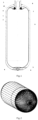
- An embodiment of the high pressure container according to the proposed invention looks the same as in the drawing of the prior art document EP3094914 (A1), the only difference being in the structure and composition of the reinforcing layer.
- the figures in this drawing illustrate the container structure and winding patterns:
- the composite high pressure container for storing pressurized liquids and gases is manufactured in a sequence of operations: i) blow molding a plastic preform into final shape of the casing 1, ii) connecting the casing with a connection fitting 3 having a retaining collar 7 and an external annular boss 8, iii) connecting the casing with a bottom unit 4 having branched wings 5 and annular bosses 6, and iv) strengthening the container according to the claimed method by making a composite reinforcement 2 on the casing surface.
- the casing is immobilized in the connection fitting by gaskets (not shown) placed in a sealing groove 9 and a fixing groove 10.
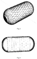
- the composite reinforcing layer is fabricated by winding a bundle of filaments according to three winding patterns: helical, polar, and hoop.
- the sequence of winding in this embodiment of the invention follows the scheme: four wraps in polar pattern, three wraps in helical pattern, three wraps in hoop pattern, and finally one wrap in polar pattern.
Landscapes
- Engineering & Computer Science (AREA)
- Mechanical Engineering (AREA)
- Chemical & Material Sciences (AREA)
- Composite Materials (AREA)
- Moulding By Coating Moulds (AREA)
- Pressure Vessels And Lids Thereof (AREA)
- Filling Or Discharging Of Gas Storage Vessels (AREA)
Claims (12)
- Verfahren zur Herstellung eines Hochdruckbehälters mit einem Gehäuse (1), das mit einer äußeren Verbundstoff-Verstärkungsschicht (2) verstärkt ist, das folgende Schritte umfasst:A) die Außenfläche des Gehäuses (1) des Behälters wird mit einer dünnen Antihaftschicht bedeckt, die verhindert, dass sich die Verstärkungsschicht (2) mit dem Gehäuse (1) verbindet;B) ein Imprägnierungsgemisch aus einer Harzzusammensetzung und einem Nanoadditiv wird in einer Mischvorrichtung bei einem Druck hergestellt, der unter einem Normaldruck von 1013 hPa liegt;C) das Imprägnierungsgemisch wird in eine Harzschale einer Wickelmaschine gegossen;D) mindestens eine Spule aus Kohlenstofffaserbündeln, wobei jedes Kohlenstofffaserbündel mindestens 4 tausend, vorzugsweise 24 bis 36 tausend Kohlenstofffilamente enthält, ist auf der Wickelmaschine montiert;E) ein Härter wird dem Imprägnierungsgemisch in einem Verhältnis von 29-30 Gew.-% des Imprägnierungsgemisches zugesetzt;F) die Kohlenstofffaserbündel werden in einem Harzbad unter Verwendung der Harzwanne so imprägniert, dass das imprägnierte Kohlenstofffaserbündel mindestens 65 Gew.-% der Kohlenstofffilamente und höchstens 35 Gew.-% der Zusammensetzung des Imprägnierungsgemisches und des Härters enthält;G) die Kohlenstofffaserbündel werden auf das Gehäuse (1) gewickelt, indem die imprägnierten Kohlenstofffaserbündel in mindestens 6 verschiedenen Wickelmustern gewickelt werden;H) die entstehende Verbundstoff-Verstärkungsschicht (2) wird thermisch ausgehärtet,und wobei die zur Herstellung des Imprägnierungsgemisches verwendete Harzzusammensetzung aus mindestens 75 Gew.-%, vorzugsweise 75-95 Gew.-% Bis-[4-(2,3-epoxypropoxy)phenyl]propan und bis zu 25 Gew.-% Bis-[4-(2,3-epoxypropoxy)phenyl]propan, vorzugsweise 5-25 Gew.% 1,4-Bis(2,3-epoxypropoxy)butan besteht, das Nanoadditiv besteht zu mindestens 80 Gew.% aus Graphen-Nanoröhren GNTs, höchstens 15 Gew.% aus Eisen (Fe) Nanopartikel und höchstens 5 % anderer allotroper Formen von Kohlenstoff wie Graphenflocken oder Fullerene und Feuchtigkeit, wobei GNTs einwandige Graphen-Nanoröhren (SWGNTs) sind und einen Durchmesser von 1-2 nm und eine Länge von höchstens 20 Mikrometern aufweisen, und Länge-zu-Durchmesser-Verhältnis von mindestens 100, und wobei das Imprägnierungsgemisch 99,9-99,99 Gew.-% der Harzzusammensetzung und 0,01-0,1 Gew.-% des Nanoadditivs enthält.
- Verfahren nach Anspruch 1, dadurch gekennzeichnet, dass der Druck in der Mischvorrichtung auf unter 500 hPa, vorzugsweise 50-500 hPa, eingestellt wird.
- Verfahren nach einem der Ansprüche 1 bis 2, dadurch gekennzeichnet, dass das Mischen des Imprägnierungsgemisches aus drei Schritten besteht:a) Rühren in der Mischvorrichtung mit Dispergierschaufel, die mit einer Umfangsgeschwindigkeit von 7-15 m/s rotiert, für mindestens 2,5 min/kg Gemisch;b) Rühren in der Mischvorrichtung mit einem Ultraschallrührer mit einer Nennleistung von mindestens 130 W und einer Nennfrequenz von mindestens 20 kHz für mindestens 2,5 Minuten/kg Gemisch;c) stetiger Druckanstieg in der Mischvorrichtung auf Normaldruck von 1013 hPa für 5 bis 60 Sekunden.
- Verfahren nach einem der Ansprüche 1 bis 3, dadurch gekennzeichnet, dass der Härter aus 20-70 Gew.-% Polyoxypropylendiamin, 20-70 Gew.-% Diaminomethylcyclohexan und höchstens 20 Gew.-% 2-Methylcyclohexan -1,3-Diamin besteht.
- Verfahren nach einem der Ansprüche 1 bis 4, dadurch gekennzeichnet, dass die Antihaftschicht aus stark hydrodesulfuriertem Benzin besteht.
- Verfahren nach einem der Ansprüche 1 bis 5, dadurch gekennzeichnet, dass der Durchmesser der Kohlenstofffaserbündel 4-10 Mikrometer beträgt und die Spannung der Kohlenstofffaserbündel in der Wickelmaschine auf mindestens 10 N eingestellt ist.
- Verfahren nach einem der Ansprüche 1 bis 6, dadurch gekennzeichnet, dass sich die Wickelmuster in den Wickelwinkeln und dem Grad der Flächenbedeckung voneinander unterscheiden.
- Verfahren nach einem der Ansprüche 1 bis 7, dadurch gekennzeichnet, dass die Wickelmuster Spiral-, Polar- und Ringmuster umfassen.
- Verfahren nach einem der Ansprüche 1 bis 8, dadurch gekennzeichnet, dass die thermische Härtung aus folgenden Schritten besteht:1) 24 h bei Raumtemperatur von 20-23 °C;2) 2 h bei Raumtemperatur steigend bis 45 °C;3) 4 h bei Temperatur von 45 °C;4) 8 h bei Raumtemperatur steigend bis 85 °C;5) 12 h bei Temperatur von 85 °C;6) freie Kühlung auf Umgebungstemperatur.
- Hochdruckbehälter, erhalten durch das Verfahren nach Anspruch 1 und umfassend ein Gehäuse (1) und eine äußere Verbundstoff-Verstärkungsschicht (2), die aus Kohlenstofffaserbündeln besteht, die um die Außenfläche des Gehäuses (1) gewickelt und mit einem ausgehärteten Imprägnierungsgemisch aus Harzzusammensetzung und Nanoadditiv, dadurch gekennzeichnet, dass die zur Herstellung des Imprägnierungsgemisches verwendete Harzzusammensetzung zu mindestens 75 Gew.-%, vorzugsweise 75-95 Gew.-% aus Bis-[4-(2,3-epoxypropoxy)phenyl]propan besteht, und bis zu 25 Gew.-%, vorzugsweise 5-25 Gew.-% 1,4-Bis(2,3-epoxypropoxy)butan, das Nanoadditiv zu mindestens 80 Gew.-% aus Graphen-Nanoröhrchen GNTs, höchstens 15 Gew.-% aus Eisen (Fe)-Nanopartikeln und höchstens 5 % aus anderen allotropen Formen von Kohlenstoff wie Graphenflocken oder Fullerenen und Feuchtigkeit besteht, wobei GNTs einwandige Graphen-Nanoröhren (SWGNTs) sind und einen Durchmesser von 1-2 nm und eine Länge von höchstens 20 Mikrometer und ein Länge-zu-Durchmesser-Verhältnis von mindestens 100, aufweisen und dass das Imprägnierungsgemisch 99,9-99,99 Gew.-% der Harzzusammensetzung und 0,01-0,1 Gew.-% des Nanoadditivs enthält, und auch darin die äußere Verbundstoff-Verstärkungsschicht (2) durch Faserwickeln mit mindestens 6 verschiedenen Wickelmustern umwickelt ist und wobei jedes Kohlenstofffaserbündel mindestens 4 tausend, vorzugsweise 24 bis 36 tausend Kohlenstofffasern enthält.
- Hochdruckbehälter nach Anspruch 10, dadurch gekennzeichnet, dass der Härter aus 20-70 Gew.-% Polyoxypropylendiamin, 20-70 Gew.-% Diaminomethylcyclohexan und höchstens 20 Gew.-% 2-Methylcyclohexan -1,3-Diamin besteht.
- Hochdruckbehälter nach Anspruch 10 oder 11, dadurch gekennzeichnet, dass der Durchmesser der Kohlenstofffaserbündel 4 bis 10 Mikrometer beträgt und die Kohlenstofffaserbündel auf das Gehäuse (1) gewickelt sind, indem die imprägnierten Kohlenstofffaserbündel in mindestens 6 Wickelmustern gewickelt werden, die sich in Wicklungswinkeln und Grad der Oberflächenbedeckung unterscheiden, vorzugsweise sind es Spiral-, Polar- und Ringmuster.
Priority Applications (3)
| Application Number | Priority Date | Filing Date | Title |
|---|---|---|---|
| EP19460050.8A EP3795340B1 (de) | 2019-09-23 | 2019-09-23 | Hochdruckbehälter und verfahren zu dessen herstellung |
| DK19460050.8T DK3795340T3 (en) | 2019-09-23 | 2019-09-23 | High pressure container and method of its manufacture |
| PL19460050.8T PL3795340T3 (pl) | 2019-09-23 | 2019-09-23 | Pojemnik wysokociśnieniowy i sposób jego wytwarzania |
Applications Claiming Priority (1)
| Application Number | Priority Date | Filing Date | Title |
|---|---|---|---|
| EP19460050.8A EP3795340B1 (de) | 2019-09-23 | 2019-09-23 | Hochdruckbehälter und verfahren zu dessen herstellung |
Publications (2)
| Publication Number | Publication Date |
|---|---|
| EP3795340A1 EP3795340A1 (de) | 2021-03-24 |
| EP3795340B1 true EP3795340B1 (de) | 2024-10-30 |
Family
ID=68289900
Family Applications (1)
| Application Number | Title | Priority Date | Filing Date |
|---|---|---|---|
| EP19460050.8A Active EP3795340B1 (de) | 2019-09-23 | 2019-09-23 | Hochdruckbehälter und verfahren zu dessen herstellung |
Country Status (3)
| Country | Link |
|---|---|
| EP (1) | EP3795340B1 (de) |
| DK (1) | DK3795340T3 (de) |
| PL (1) | PL3795340T3 (de) |
Families Citing this family (5)
| Publication number | Priority date | Publication date | Assignee | Title |
|---|---|---|---|---|
| CN113370552B (zh) * | 2021-05-26 | 2021-12-14 | 南京航空航天大学 | 一种基于变曲率异形回转体的三维编织机离散化芯模系统 |
| CN115355439B (zh) * | 2022-09-20 | 2024-04-30 | 北京天海氢能装备有限公司 | 一种车用高压气瓶的铺层方法 |
| EP4552704B1 (de) * | 2023-11-09 | 2025-12-31 | Dräger Safety AG & Co. KGaA | Beatmungsvorrichtung, druckbehälter und zugehörige verfahren zur herstellung |
| GB2637472A (en) * | 2023-12-11 | 2025-07-30 | Viritech Ltd | A method of manufacturing a composite pressure vessel and a composite pressure vessel |
| CN119036721B (zh) * | 2024-09-25 | 2025-10-28 | 杭州恒峰塑料制品有限公司 | 一种耐热型多层阻隔复合瓶制备工艺 |
Family Cites Families (14)
| Publication number | Priority date | Publication date | Assignee | Title |
|---|---|---|---|---|
| US3282757A (en) | 1962-12-14 | 1966-11-01 | Structural Fibers | Method of making a filament reinforced pressure vessel |
| BE902543A (nl) | 1985-05-30 | 1985-09-16 | Duktrad Internat | Halsafsluitring voor kunststof druktanks. |
| CA1326832C (fr) | 1987-07-21 | 1994-02-08 | Claude Leon Hembert | Reservoir de fluide et son procede de fabrication |
| SE463834B (sv) | 1988-03-15 | 1991-01-28 | Asea Plast Ab | Tryckkaerl |
| US5150812A (en) * | 1990-07-05 | 1992-09-29 | Hoechst Celanese Corporation | Pressurized and/or cryogenic gas containers and conduits made with a gas impermeable polymer |
| US5253778A (en) | 1992-01-28 | 1993-10-19 | Edo Canada Ltd. | Fluid pressure vessel boss-liner attachment system |
| DE19526154C2 (de) | 1995-07-10 | 1997-04-17 | Mannesmann Ag | Composite-Druckbehälter zur Speicherung von gasförmigen Medien unter Druck mit einem Liner aus Kunststoff |
| US5568878A (en) * | 1996-01-11 | 1996-10-29 | Essef Corporation | Filament wound pressure vessel having a reinforced access opening |
| PL203938B1 (pl) | 2004-04-13 | 2009-11-30 | Stako Irena Staniuk Jacek Stan | Zbiornik kompozytowy i sposób jego wytwarzania |
| EP2112423A1 (de) | 2008-04-25 | 2009-10-28 | Sakowsky, Jon | Mehrschichtiger Behälter zur Flüssigkeit- und Gasaufbewahrung unter erhöhtem Druck und Herstellungsverfahren dafür |
| PL228200B1 (pl) | 2008-11-18 | 2018-02-28 | Adam Saferna | Pojemnik wysokocisnieniowy |
| JP2015528068A (ja) * | 2012-06-05 | 2015-09-24 | アプライド ナノストラクチャード ソリューションズ リミテッド ライアビリティー カンパニーApplied Nanostructuredsolutions, Llc | Cns導入カーボン・ナノ材料及びそのためのプロセス |
| PL226196B1 (pl) | 2014-01-15 | 2017-06-30 | Techplast Spółka Z Ograniczoną Odpowiedzialnością | Kompozytowy zbiornik wysokocisnieniowy oraz sposob wytwarzania kompozytowego zbiornika wysokocisnieniowego |
| JP2017115938A (ja) | 2015-12-22 | 2017-06-29 | ニッタ株式会社 | 高圧容器および高圧容器の製造方法 |
-
2019
- 2019-09-23 EP EP19460050.8A patent/EP3795340B1/de active Active
- 2019-09-23 DK DK19460050.8T patent/DK3795340T3/da active
- 2019-09-23 PL PL19460050.8T patent/PL3795340T3/pl unknown
Also Published As
| Publication number | Publication date |
|---|---|
| PL3795340T3 (pl) | 2025-03-31 |
| EP3795340A1 (de) | 2021-03-24 |
| DK3795340T3 (en) | 2025-01-27 |
Similar Documents
| Publication | Publication Date | Title |
|---|---|---|
| EP3795340B1 (de) | Hochdruckbehälter und verfahren zu dessen herstellung | |
| Peters | Composite filament winding | |
| JP5426806B2 (ja) | 繊維強化圧力容器 | |
| US5188872A (en) | Composite structural member with high bending strength | |
| USRE35081E (en) | Composite structural member with high bending strength | |
| JP4588307B2 (ja) | 耐圧容器製造方法 | |
| US20150192251A1 (en) | High pressure carbon composite pressure vessel | |
| JP5238577B2 (ja) | 複合容器及び複合容器の製造方法 | |
| CN101784703B (zh) | 热固性树脂纤维 | |
| WO2010135159A1 (en) | High pressure storage device and method | |
| US20150292677A1 (en) | Method of manufacturing a compressed gas cylinder | |
| EP4220002A1 (de) | Druckbehälter | |
| JP2016142349A (ja) | 圧力容器 | |
| JP4578068B2 (ja) | シェル用積層体及びこれを用いた圧力容器 | |
| WO2003020535A2 (en) | Reinforced carbon fiber comprising spoke for bicycle wheel | |
| JP2000035196A (ja) | 圧力容器およびその製造方法 | |
| JP2005113963A (ja) | 耐圧容器製造方法 | |
| JP4431351B2 (ja) | 耐圧容器製造方法 | |
| JP2004502573A (ja) | コア入り賦形複合構造部材及びその製造方法 | |
| CN100398303C (zh) | 纤维增强塑料成形体和制造该成形体的方法 | |
| JP3156130B2 (ja) | 大きな曲げ強さを持つ複合構造部材並びに製造方法 | |
| EP2788664A1 (de) | Verbunddruckbehälter und herstellungsverfahren dafür | |
| JP2002031277A (ja) | 連続長のコンポジット輸送管 | |
| CN117957395B (zh) | 具有优化的外部复合结构的压力容器 | |
| JPH05508115A (ja) | 大きな曲げ強さを持つ複合構造部材並びに製造方法 |
Legal Events
| Date | Code | Title | Description |
|---|---|---|---|
| PUAI | Public reference made under article 153(3) epc to a published international application that has entered the european phase |
Free format text: ORIGINAL CODE: 0009012 |
|
| STAA | Information on the status of an ep patent application or granted ep patent |
Free format text: STATUS: THE APPLICATION HAS BEEN PUBLISHED |
|
| AK | Designated contracting states |
Kind code of ref document: A1 Designated state(s): AL AT BE BG CH CY CZ DE DK EE ES FI FR GB GR HR HU IE IS IT LI LT LU LV MC MK MT NL NO PL PT RO RS SE SI SK SM TR |
|
| AX | Request for extension of the european patent |
Extension state: BA ME |
|
| STAA | Information on the status of an ep patent application or granted ep patent |
Free format text: STATUS: REQUEST FOR EXAMINATION WAS MADE |
|
| 17P | Request for examination filed |
Effective date: 20210430 |
|
| RBV | Designated contracting states (corrected) |
Designated state(s): AL AT BE BG CH CY CZ DE DK EE ES FI FR GB GR HR HU IE IS IT LI LT LU LV MC MK MT NL NO PL PT RO RS SE SI SK SM TR |
|
| RAP1 | Party data changed (applicant data changed or rights of an application transferred) |
Owner name: TECHPLAST SPOLKA Z O.O. |
|
| RIN1 | Information on inventor provided before grant (corrected) |
Inventor name: SAFERNA, PIOTR Inventor name: SAFERNA, ADAM |
|
| STAA | Information on the status of an ep patent application or granted ep patent |
Free format text: STATUS: EXAMINATION IS IN PROGRESS |
|
| 17Q | First examination report despatched |
Effective date: 20230911 |
|
| RIC1 | Information provided on ipc code assigned before grant |
Ipc: B29C 53/60 20060101ALI20240312BHEP Ipc: B29C 53/56 20060101ALI20240312BHEP Ipc: B29C 53/00 20060101ALI20240312BHEP Ipc: B29C 70/86 20060101ALI20240312BHEP Ipc: B29C 70/32 20060101ALI20240312BHEP Ipc: B29C 70/08 20060101AFI20240312BHEP |
|
| GRAP | Despatch of communication of intention to grant a patent |
Free format text: ORIGINAL CODE: EPIDOSNIGR1 |
|
| STAA | Information on the status of an ep patent application or granted ep patent |
Free format text: STATUS: GRANT OF PATENT IS INTENDED |
|
| INTG | Intention to grant announced |
Effective date: 20240626 |
|
| GRAS | Grant fee paid |
Free format text: ORIGINAL CODE: EPIDOSNIGR3 |
|
| GRAA | (expected) grant |
Free format text: ORIGINAL CODE: 0009210 |
|
| STAA | Information on the status of an ep patent application or granted ep patent |
Free format text: STATUS: THE PATENT HAS BEEN GRANTED |
|
| AK | Designated contracting states |
Kind code of ref document: B1 Designated state(s): AL AT BE BG CH CY CZ DE DK EE ES FI FR GB GR HR HU IE IS IT LI LT LU LV MC MK MT NL NO PL PT RO RS SE SI SK SM TR |
|
| REG | Reference to a national code |
Ref country code: GB Ref legal event code: FG4D |
|
| REG | Reference to a national code |
Ref country code: CH Ref legal event code: EP |
|
| REG | Reference to a national code |
Ref country code: DE Ref legal event code: R096 Ref document number: 602019061074 Country of ref document: DE |
|
| REG | Reference to a national code |
Ref country code: IE Ref legal event code: FG4D |
|
| REG | Reference to a national code |
Ref country code: DK Ref legal event code: T3 Effective date: 20250121 |
|
| REG | Reference to a national code |
Ref country code: LT Ref legal event code: MG9D |
|
| REG | Reference to a national code |
Ref country code: NL Ref legal event code: MP Effective date: 20241030 |
|
| PG25 | Lapsed in a contracting state [announced via postgrant information from national office to epo] |
Ref country code: PT Free format text: LAPSE BECAUSE OF FAILURE TO SUBMIT A TRANSLATION OF THE DESCRIPTION OR TO PAY THE FEE WITHIN THE PRESCRIBED TIME-LIMIT Effective date: 20250228 Ref country code: IS Free format text: LAPSE BECAUSE OF FAILURE TO SUBMIT A TRANSLATION OF THE DESCRIPTION OR TO PAY THE FEE WITHIN THE PRESCRIBED TIME-LIMIT Effective date: 20250228 Ref country code: HR Free format text: LAPSE BECAUSE OF FAILURE TO SUBMIT A TRANSLATION OF THE DESCRIPTION OR TO PAY THE FEE WITHIN THE PRESCRIBED TIME-LIMIT Effective date: 20241030 |
|
| PG25 | Lapsed in a contracting state [announced via postgrant information from national office to epo] |
Ref country code: FI Free format text: LAPSE BECAUSE OF FAILURE TO SUBMIT A TRANSLATION OF THE DESCRIPTION OR TO PAY THE FEE WITHIN THE PRESCRIBED TIME-LIMIT Effective date: 20241030 Ref country code: NL Free format text: LAPSE BECAUSE OF FAILURE TO SUBMIT A TRANSLATION OF THE DESCRIPTION OR TO PAY THE FEE WITHIN THE PRESCRIBED TIME-LIMIT Effective date: 20241030 |
|
| REG | Reference to a national code |
Ref country code: AT Ref legal event code: MK05 Ref document number: 1736520 Country of ref document: AT Kind code of ref document: T Effective date: 20241030 |
|
| PG25 | Lapsed in a contracting state [announced via postgrant information from national office to epo] |
Ref country code: BG Free format text: LAPSE BECAUSE OF FAILURE TO SUBMIT A TRANSLATION OF THE DESCRIPTION OR TO PAY THE FEE WITHIN THE PRESCRIBED TIME-LIMIT Effective date: 20241030 |
|
| PG25 | Lapsed in a contracting state [announced via postgrant information from national office to epo] |
Ref country code: ES Free format text: LAPSE BECAUSE OF FAILURE TO SUBMIT A TRANSLATION OF THE DESCRIPTION OR TO PAY THE FEE WITHIN THE PRESCRIBED TIME-LIMIT Effective date: 20241030 |
|
| PG25 | Lapsed in a contracting state [announced via postgrant information from national office to epo] |
Ref country code: NO Free format text: LAPSE BECAUSE OF FAILURE TO SUBMIT A TRANSLATION OF THE DESCRIPTION OR TO PAY THE FEE WITHIN THE PRESCRIBED TIME-LIMIT Effective date: 20250130 |
|
| PG25 | Lapsed in a contracting state [announced via postgrant information from national office to epo] |
Ref country code: AT Free format text: LAPSE BECAUSE OF FAILURE TO SUBMIT A TRANSLATION OF THE DESCRIPTION OR TO PAY THE FEE WITHIN THE PRESCRIBED TIME-LIMIT Effective date: 20241030 Ref country code: GR Free format text: LAPSE BECAUSE OF FAILURE TO SUBMIT A TRANSLATION OF THE DESCRIPTION OR TO PAY THE FEE WITHIN THE PRESCRIBED TIME-LIMIT Effective date: 20250131 Ref country code: LV Free format text: LAPSE BECAUSE OF FAILURE TO SUBMIT A TRANSLATION OF THE DESCRIPTION OR TO PAY THE FEE WITHIN THE PRESCRIBED TIME-LIMIT Effective date: 20241030 |
|
| PGFP | Annual fee paid to national office [announced via postgrant information from national office to epo] |
Ref country code: FR Payment date: 20250331 Year of fee payment: 7 |
|
| PG25 | Lapsed in a contracting state [announced via postgrant information from national office to epo] |
Ref country code: RS Free format text: LAPSE BECAUSE OF FAILURE TO SUBMIT A TRANSLATION OF THE DESCRIPTION OR TO PAY THE FEE WITHIN THE PRESCRIBED TIME-LIMIT Effective date: 20250130 |
|
| PG25 | Lapsed in a contracting state [announced via postgrant information from national office to epo] |
Ref country code: SM Free format text: LAPSE BECAUSE OF FAILURE TO SUBMIT A TRANSLATION OF THE DESCRIPTION OR TO PAY THE FEE WITHIN THE PRESCRIBED TIME-LIMIT Effective date: 20241030 |
|
| PG25 | Lapsed in a contracting state [announced via postgrant information from national office to epo] |
Ref country code: EE Free format text: LAPSE BECAUSE OF FAILURE TO SUBMIT A TRANSLATION OF THE DESCRIPTION OR TO PAY THE FEE WITHIN THE PRESCRIBED TIME-LIMIT Effective date: 20241030 |
|
| PG25 | Lapsed in a contracting state [announced via postgrant information from national office to epo] |
Ref country code: RO Free format text: LAPSE BECAUSE OF FAILURE TO SUBMIT A TRANSLATION OF THE DESCRIPTION OR TO PAY THE FEE WITHIN THE PRESCRIBED TIME-LIMIT Effective date: 20241030 |
|
| PG25 | Lapsed in a contracting state [announced via postgrant information from national office to epo] |
Ref country code: SK Free format text: LAPSE BECAUSE OF FAILURE TO SUBMIT A TRANSLATION OF THE DESCRIPTION OR TO PAY THE FEE WITHIN THE PRESCRIBED TIME-LIMIT Effective date: 20241030 |
|
| PG25 | Lapsed in a contracting state [announced via postgrant information from national office to epo] |
Ref country code: CZ Free format text: LAPSE BECAUSE OF FAILURE TO SUBMIT A TRANSLATION OF THE DESCRIPTION OR TO PAY THE FEE WITHIN THE PRESCRIBED TIME-LIMIT Effective date: 20241030 |
|
| REG | Reference to a national code |
Ref country code: DE Ref legal event code: R097 Ref document number: 602019061074 Country of ref document: DE |
|
| PLBE | No opposition filed within time limit |
Free format text: ORIGINAL CODE: 0009261 |
|
| STAA | Information on the status of an ep patent application or granted ep patent |
Free format text: STATUS: NO OPPOSITION FILED WITHIN TIME LIMIT |
|
| PG25 | Lapsed in a contracting state [announced via postgrant information from national office to epo] |
Ref country code: SE Free format text: LAPSE BECAUSE OF FAILURE TO SUBMIT A TRANSLATION OF THE DESCRIPTION OR TO PAY THE FEE WITHIN THE PRESCRIBED TIME-LIMIT Effective date: 20241030 |
|
| 26N | No opposition filed |
Effective date: 20250731 |
|
| PGFP | Annual fee paid to national office [announced via postgrant information from national office to epo] |
Ref country code: DK Payment date: 20250909 Year of fee payment: 7 Ref country code: DE Payment date: 20250822 Year of fee payment: 7 |
|
| PGFP | Annual fee paid to national office [announced via postgrant information from national office to epo] |
Ref country code: PL Payment date: 20250820 Year of fee payment: 7 Ref country code: TR Payment date: 20250808 Year of fee payment: 7 Ref country code: IT Payment date: 20250910 Year of fee payment: 7 |
|
| PGFP | Annual fee paid to national office [announced via postgrant information from national office to epo] |
Ref country code: GB Payment date: 20250729 Year of fee payment: 7 |