EP3795294A1 - Dispositif pivotant pour broche de pièce d'une machine-outil, porte-outil pour machine-outil et machine-outil - Google Patents
Dispositif pivotant pour broche de pièce d'une machine-outil, porte-outil pour machine-outil et machine-outil Download PDFInfo
- Publication number
- EP3795294A1 EP3795294A1 EP20184180.6A EP20184180A EP3795294A1 EP 3795294 A1 EP3795294 A1 EP 3795294A1 EP 20184180 A EP20184180 A EP 20184180A EP 3795294 A1 EP3795294 A1 EP 3795294A1
- Authority
- EP
- European Patent Office
- Prior art keywords
- workpiece
- spindle
- tool
- machine tool
- workpiece spindle
- Prior art date
- Legal status (The legal status is an assumption and is not a legal conclusion. Google has not performed a legal analysis and makes no representation as to the accuracy of the status listed.)
- Pending
Links
- 238000003754 machining Methods 0.000 claims abstract description 72
- 239000000463 material Substances 0.000 claims abstract description 21
- 239000002184 metal Substances 0.000 claims abstract description 9
- 229910052751 metal Inorganic materials 0.000 claims abstract description 9
- 238000003801 milling Methods 0.000 claims description 24
- 238000000227 grinding Methods 0.000 claims description 19
- 239000011265 semifinished product Substances 0.000 claims description 5
- 230000001939 inductive effect Effects 0.000 claims description 3
- 230000001419 dependent effect Effects 0.000 claims description 2
- 239000000969 carrier Substances 0.000 description 4
- 238000005520 cutting process Methods 0.000 description 4
- 238000012546 transfer Methods 0.000 description 4
- 238000000151 deposition Methods 0.000 description 2
- 238000005553 drilling Methods 0.000 description 2
- 238000012986 modification Methods 0.000 description 2
- 230000004048 modification Effects 0.000 description 2
- 238000003860 storage Methods 0.000 description 2
- 230000001360 synchronised effect Effects 0.000 description 2
- 208000012886 Vertigo Diseases 0.000 description 1
- 238000010276 construction Methods 0.000 description 1
- 238000013461 design Methods 0.000 description 1
- 238000006073 displacement reaction Methods 0.000 description 1
- 238000000034 method Methods 0.000 description 1
- 238000012806 monitoring device Methods 0.000 description 1
- 238000012544 monitoring process Methods 0.000 description 1
- 238000012549 training Methods 0.000 description 1
- 238000007514 turning Methods 0.000 description 1
Images


Classifications
-
- B—PERFORMING OPERATIONS; TRANSPORTING
- B23—MACHINE TOOLS; METAL-WORKING NOT OTHERWISE PROVIDED FOR
- B23Q—DETAILS, COMPONENTS, OR ACCESSORIES FOR MACHINE TOOLS, e.g. ARRANGEMENTS FOR COPYING OR CONTROLLING; MACHINE TOOLS IN GENERAL CHARACTERISED BY THE CONSTRUCTION OF PARTICULAR DETAILS OR COMPONENTS; COMBINATIONS OR ASSOCIATIONS OF METAL-WORKING MACHINES, NOT DIRECTED TO A PARTICULAR RESULT
- B23Q39/00—Metal-working machines incorporating a plurality of sub-assemblies, each capable of performing a metal-working operation
- B23Q39/04—Metal-working machines incorporating a plurality of sub-assemblies, each capable of performing a metal-working operation the sub-assemblies being arranged to operate simultaneously at different stations, e.g. with an annular work-table moved in steps
- B23Q39/048—Metal-working machines incorporating a plurality of sub-assemblies, each capable of performing a metal-working operation the sub-assemblies being arranged to operate simultaneously at different stations, e.g. with an annular work-table moved in steps the work holder of a work station transfers directly its workpiece to the work holder of a following work station
-
- B—PERFORMING OPERATIONS; TRANSPORTING
- B23—MACHINE TOOLS; METAL-WORKING NOT OTHERWISE PROVIDED FOR
- B23Q—DETAILS, COMPONENTS, OR ACCESSORIES FOR MACHINE TOOLS, e.g. ARRANGEMENTS FOR COPYING OR CONTROLLING; MACHINE TOOLS IN GENERAL CHARACTERISED BY THE CONSTRUCTION OF PARTICULAR DETAILS OR COMPONENTS; COMBINATIONS OR ASSOCIATIONS OF METAL-WORKING MACHINES, NOT DIRECTED TO A PARTICULAR RESULT
- B23Q1/00—Members which are comprised in the general build-up of a form of machine, particularly relatively large fixed members
- B23Q1/25—Movable or adjustable work or tool supports
- B23Q1/44—Movable or adjustable work or tool supports using particular mechanisms
- B23Q1/50—Movable or adjustable work or tool supports using particular mechanisms with rotating pairs only, the rotating pairs being the first two elements of the mechanism
- B23Q1/52—Movable or adjustable work or tool supports using particular mechanisms with rotating pairs only, the rotating pairs being the first two elements of the mechanism a single rotating pair
-
- B—PERFORMING OPERATIONS; TRANSPORTING
- B23—MACHINE TOOLS; METAL-WORKING NOT OTHERWISE PROVIDED FOR
- B23B—TURNING; BORING
- B23B3/00—General-purpose turning-machines or devices, e.g. centre lathes with feed rod and lead screw; Sets of turning-machines
- B23B3/30—Turning-machines with two or more working-spindles, e.g. in fixed arrangement
-
- B—PERFORMING OPERATIONS; TRANSPORTING
- B23—MACHINE TOOLS; METAL-WORKING NOT OTHERWISE PROVIDED FOR
- B23Q—DETAILS, COMPONENTS, OR ACCESSORIES FOR MACHINE TOOLS, e.g. ARRANGEMENTS FOR COPYING OR CONTROLLING; MACHINE TOOLS IN GENERAL CHARACTERISED BY THE CONSTRUCTION OF PARTICULAR DETAILS OR COMPONENTS; COMBINATIONS OR ASSOCIATIONS OF METAL-WORKING MACHINES, NOT DIRECTED TO A PARTICULAR RESULT
- B23Q2210/00—Machine tools incorporating a specific component
- B23Q2210/004—Torque motors
-
- B—PERFORMING OPERATIONS; TRANSPORTING
- B23—MACHINE TOOLS; METAL-WORKING NOT OTHERWISE PROVIDED FOR
- B23Q—DETAILS, COMPONENTS, OR ACCESSORIES FOR MACHINE TOOLS, e.g. ARRANGEMENTS FOR COPYING OR CONTROLLING; MACHINE TOOLS IN GENERAL CHARACTERISED BY THE CONSTRUCTION OF PARTICULAR DETAILS OR COMPONENTS; COMBINATIONS OR ASSOCIATIONS OF METAL-WORKING MACHINES, NOT DIRECTED TO A PARTICULAR RESULT
- B23Q2220/00—Machine tool components
- B23Q2220/006—Spindle heads
-
- B—PERFORMING OPERATIONS; TRANSPORTING
- B23—MACHINE TOOLS; METAL-WORKING NOT OTHERWISE PROVIDED FOR
- B23Q—DETAILS, COMPONENTS, OR ACCESSORIES FOR MACHINE TOOLS, e.g. ARRANGEMENTS FOR COPYING OR CONTROLLING; MACHINE TOOLS IN GENERAL CHARACTERISED BY THE CONSTRUCTION OF PARTICULAR DETAILS OR COMPONENTS; COMBINATIONS OR ASSOCIATIONS OF METAL-WORKING MACHINES, NOT DIRECTED TO A PARTICULAR RESULT
- B23Q2707/00—Automatic supply or removal of metal workpieces
- B23Q2707/003—Automatic supply or removal of metal workpieces in a lathe
Definitions
- the present invention relates to a swivel device for a workpiece spindle of a machine tool, a tool carrier for a machine tool and a machine tool for machining workpieces, in particular bar material.
- the present invention also relates to a loading and unloading system for a machine tool for supplying workpieces to be machined and / or removing workpieces machined by the machine tool.
- Machine tools for machining workpieces are known in which both ends of the workpiece can be machined in one machine tool, i.e. two-sided machining of the workpiece can be carried out.
- a lathe of this type described is mounted in each of two headstocks so that a workpiece spindle can be driven in a rotating manner.
- Each headstock carries a tool holder on the side opposite the workpiece spindle.
- the tools received therein are used to machine the workpiece clamped on the workpiece spindle of the other headstock.
- the workpiece is picked up in the vertical alignment of the first workpiece spindle by its workpiece clamping device from a horizontal support, after this first workpiece spindle has been swiveled into the horizontal, it is processed by the tools that sit in the tool holder of the second headstock and then transferred to the chuck of the second workpiece spindle.
- the second side of the workpiece is then machined by the tools provided on the first headstock and, after pivoting the second workpiece spindle into the vertical position, placed on a workpiece support surface.
- each headstock carries both a workpiece spindle and tools, and both headstocks are involved in the machining process during machining, only one workpiece can be machined during the machining time and no other workpiece can be handled during this time.
- the time from picking up an initial workpiece to depositing a completely machined workpiece is therefore comparatively long and the throughput of such lathes is rather low.
- horizontal supports for workpieces are provided below the workpiece clamping means, which can be pivoted vertically downwards with the workpiece spindles, the workpiece spindles for machining the workpieces held in the workpiece clamping means being designed in a hanging arrangement with a vertical axis of rotation and a tool holder being arranged below the hanging workpiece clamping means on the machine bed.
- the second workpiece spindle can be pivoted about a pivot axis running transversely to the second spindle axis, namely from a position in which the second spindle axis runs parallel or coaxially to the first spindle axis to a position in which the second spindle axis is transverse to the first Spindle axis is aligned.
- first tool carrier equipped with at least one tool for machining a workpiece held in the first workpiece spindle on one side
- a second tool carrier equipped with at least one tool for machining a workpiece held in the second workpiece spindle on the other side.
- the first and second workpiece spindles with facing workpiece holders can be moved into a transfer position of the workpiece spindles for the direct transfer of the workpiece machined on one side from one of the workpiece holders to the other workpiece holder.
- the spindle axes are aligned coaxially to one another and in Movable in the direction of the axes, wherein the first workpiece spindle for loading the raw workpiece is assigned a bar feeder.
- the finished workpiece can be transferred from the second workpiece spindle with the second spindle axis running transversely to the first spindle axis to a workpiece removal device.
- the lathe described has the problem, however, that when the workpiece is delivered by the second workpiece spindle to the downstream workpiece removal device, the workpiece can only be positioned imprecisely on the workpiece removal device, in particular a carrier element of the workpiece removal device, whereby the position in the lathe and alignment information about the workpiece is lost when it is transferred to the workpiece removal device.
- the invention is based on the object of providing a machine tool that is capable of overlapping machining and handling operations on the one hand in order to minimize the time from picking up an initial workpiece to depositing a completely machined workpiece, and on the other hand, inclined machining on an in To perform a workpiece recorded on a workpiece spindle with high precision and a high degree of freedom. Furthermore, the provided machine tool should be able to carry out milling work with high cutting forces and to make the position and orientation information about the machined workpiece available for downstream machining steps and at the same time to realize a compact and inherently rigid construction in order to avoid unnecessary vibrations that could impair the machining result.
- a swivel device for a workpiece spindle of a machine tool in particular a lathe, according to claim 1.
- the invention provides a tool carrier for a machine tool, in particular a lathe, according to claim 10 and a machine tool, in particular lathe, according to claim 13.
- the present invention also relates to a loading and unloading system for a machine tool for supplying workpieces to be machined and / or removing workpieces machined by the machine tool.
- One of the core ideas of the present invention is a swivel device for a workpiece spindle to provide a machine tool in which the pivoting movement and / or rotary movement is driven by a torque motor or a master-slave gear drive, whereby a high position accuracy and a high drive torque or holding torque can be provided for the pivoting device and the workpiece spindle can be brought into any desired angular position and can be fixed in this.
- a workpiece spindle can be provided which enables an inclined workpiece machining of a workpiece held in the workpiece spindle.
- Due to the very high holding torque provided by the torque motor, a machine tool equipped with the pivoting device according to the invention is capable of machining workpieces, in particular milling work, with extremely high cutting forces.
- a swivel device for a workpiece spindle of a machine tool in particular a lathe, for machining a workpiece, in particular bar material, which is preferably at least partially made of metal or the like, has: a housing for attaching the swivel device to a machine tool , a carrier device for receiving a workpiece spindle of the machine tool, which is rotatably mounted in the housing, and a drive provided on the housing, in particular in the housing, for driving a pivoting and / or rotary movement of the carrier device about a pivot axis relative to the housing, the drive is a torque motor or a master-slave gear drive.
- a safety axis with fixation can be provided, which enables a work piece spindle to be swiveled continuously about a desired swivel axis.
- the swivel output as a torque motor and / or master-slave gear drive
- a high torque can be achieved with a high holding torque at the same time.
- the infinitely variable pivoting of the workpiece spindle makes it possible to carry out machining operations, in particular machining operations, in any angular or inclined position on the workpiece held in the workpiece spindle. This means that special tools can be avoided and machining in undercuts can be carried out without special tools.
- the high holding torque provided enables workpiece machining, in particular milling work, to be carried out with extremely high cutting forces.
- the torque motor is a motor with a holding torque of more than 100 Nm and is preferably designed as a direct drive, and / or the drive is set up to use a step angle of ⁇ 50 angular seconds, preferably ⁇ 10 angular seconds, more preferably ⁇ 50 arc seconds to be realized.
- the torque motor is preferably designed as a synchronous motor with a maximum torque in the range from 200 to 400 Nm and a speed in the range from 0 to 5000 rpm.
- the master-slave gear drive consists of two drives, a master drive and a slave drive, which are also preferably designed as synchronous motors, and both are operatively connected to a common drive shaft via a gear drive.
- the two drives each have a drive pinion that would come with a main gear that is attached to the drive shaft.
- the carrier device has a hollow shaft which serves as the drive shaft of the torque motor or the master-slave gear drive.
- the torque motor is designed as a central rotary drive so that both ends of a / the drive shaft are exposed, the two ends of the drive shaft preferably being rotatably mounted in the housing.
- the carrier device has a spindle carrier to which the workpiece spindle is attached in such a way that a spindle axis of a workpiece holder, which is rotatable about the spindle axis, is transverse, in particular perpendicular, to the pivot axis.
- the workpiece spindle is mounted on the spindle carrier so as to be displaceable parallel to the spindle axis by means of a guide device, in particular a slide system.
- the workpiece spindle can be rotated or pivoted about an initial position by means of the pivoting device at least by an angle of ⁇ 50 °, in particular at least by an angle of ⁇ 95 °, the initial position preferably being a vertical position of the workpiece spindle.
- the pivoting device has a clamping device, in particular a safety clamping device, which is preferably pneumatic or is hydraulically actuated.
- the safety clamping device is to be understood as meaning that the clamping device is closed in a non-actuated state, that is to say in a clamping state, and is only released by actuation, in particular by applying a pneumatic or hydraulic pressure. This can ensure that the pivot axis is clamped in the event of a fault or emergency.
- the clamping device it is possible to clamp the swivel device, in particular the workpiece spindle, steplessly, whereby a fixation with an even greater holding torque is realized.
- the swivel device has a measuring system, in particular an inductive angle measuring device. It is preferred here that the measuring system has a measuring accuracy of up to ⁇ 1 angular second.
- the pivoting device can be positioned and fixed with a very high degree of angular accuracy, as a result of which machining operations can be carried out in any angular position on the workpiece held in the pivoting device, in particular in the workpiece spindle which is attached to the pivoting device.
- a main bearing of the torque motor which is preferably arranged on the side of the drive shaft facing the carrier device, is designed as an axial / radial bearing, in particular a YRTC bearing.
- the measuring system is designed in the vicinity of the main bearing, as a result of which possible angle errors due to torsional stresses on the drive shaft can be reduced.
- the present invention further relates to a tool carrier for a machine tool, in particular a lathe, more preferably the one described below Machine tool according to the present invention, for machining a workpiece, in particular bar material, which is preferably formed at least in sections from metal or the like, comprising: a turret head comprising a plurality of tool holders for holding tools and a steady rest which is set up to hold workpieces, which are processed in a machine tool provided with the tool carrier.
- a tool carrier can be provided which enables a machine tool in which it is provided or installed to additionally support workpieces that are received in one or in two workpiece spindles, in particular their workpiece holders. This makes it possible to machine longer workpieces or workpieces with a smaller diameter without reducing the machining quality due to undesired displacements of the workpiece during machining.
- the tool carrier has a guide device, in particular a slide system, by means of which the turret head can be moved parallel to an axis of rotation of the turret head and / or a further guide device, in particular a slide system, by means of which the turret head is transverse, in particular perpendicular, to the axis of rotation of the Turret head is movable, has.
- the axis of rotation of the turret head is parallel to an axis of rotation of a workpiece that can be supported by the steady rest.
- the present invention further relates to a machine tool, in particular a lathe, for machining a workpiece, in particular bar material, which is preferably formed at least in sections from metal or the like, comprising: a Machine frame, a workpiece spindle arranged on the machine frame with a workpiece holder that can be rotated about a spindle axis, another workpiece spindle arranged on the machine frame with another workpiece holder that can be rotated about another spindle axis, a first tool carrier that can be equipped with at least one tool for machining a workpiece held in the workpiece spindle on one side , and a swivel device for swiveling and / or rotating the workpiece spindle about a swivel axis which is aligned approximately parallel to a base area on which the machine frame is set up, the workpiece spindle being steplessly reversed by means of the swivel device, in particular the swivel device according to the invention described above an initial position
- the workpiece spindle can be rotated or pivoted about an initial position by means of the pivoting device at least through an angle of ⁇ 50 °, in particular at least through an angle of ⁇ 95 °, the initial position preferably being a vertical position of the workpiece spindle.
- the pivotable workpiece spindle is arranged in front of or behind the further workpiece spindle in the machining flow direction.
- the machine tool furthermore has a second tool carrier that can be equipped with at least one tool for machining a workpiece held in the further workpiece spindle on another side, in particular the rear, with the first tool carrier and / or the second tool carrier preferably being the one above described tool carrier according to the invention is / are.
- the machine tool has a milling and / or grinding device with a tool spindle for milling and / or grinding a workpiece held in the workpiece spindle and / or in the further workpiece spindle.
- the milling and / or grinding device also has a guide device, in particular a slide system, by means of which the tool spindle can be moved transversely, in particular perpendicularly, to a spindle axis of the tool spindle, the tool spindle preferably being oriented vertically and the guide device moving enables parallel to the pivot axis of the pivoting device in a so-called Y-direction.
- a guide device in particular a slide system
- the swivel device and / or the guide device are set up in such a way that a workpiece held in the workpiece spindle can be brought into a machining area of the tool spindle, with the spindle axis of the tool spindle in particular in an oblique orientation with respect to the spindle axis of the tool spindle can be brought.
- the first tool carrier and / or the second tool carrier also has a guide device, in particular a slide system, by means of which a / the turret of the tool holder can be moved transversely, in particular perpendicularly, to the respective spindle axis, the guide device preferably moving in parallel allows for the pivot axis of the pivot device in a so-called Y direction.
- a guide device in particular a slide system, by means of which a / the turret of the tool holder can be moved transversely, in particular perpendicularly, to the respective spindle axis, the guide device preferably moving in parallel allows for the pivot axis of the pivot device in a so-called Y direction.
- first workpiece spindle and / or the second workpiece spindle is / are designed as a direct drive with a hollow shaft, in which the unmachined workpiece is preferably driven by a Hollow shaft of the direct drive can be fed to the workpiece holder.
- the first workpiece spindle and / or the second workpiece spindle is assigned a bar feed device, in particular a bar loader, with which a material bar can be fed through the hollow shaft of the direct drive to the workpiece holder.
- the machine tool has a further guide device, in particular a slide system, on which the swivel device sits and by means of which the swivel device can be moved transversely, in particular perpendicularly, to the swivel axis, in particular a movement in a so-called X direction is enabled.
- a further guide device in particular a slide system, on which the swivel device sits and by means of which the swivel device can be moved transversely, in particular perpendicularly, to the swivel axis, in particular a movement in a so-called X direction is enabled.
- the machine tool has a further guide device, in particular a slide system, on which the second tool carrier sits and can be moved parallel to the spindle axis of the second workpiece spindle, the guide device of the swivel device and the guide device of the second tool carrier preferably using common guide rails .
- the machine tool has a loading and / or unloading system
- the loading and unloading system has at least one handling system, a shuttle, a drag frame belt, a pallet belt and / or a robot
- the loading and / or Unloading system is preferably provided for loading the machine tool with material bars and / or semi-finished products and / or blanks and / or for unloading machined workpieces or partially machined or finished workpieces. It is preferably the loading and unloading system around the loading and / or unloading system according to the invention described below.
- the present invention relates to a loading and / or unloading system, comprising: at least one handling system, a shuttle, a drag frame belt, a pallet belt and / or a robot, the loading and / or unloading system preferably for loading the machine tool with material bars and / or semi-finished products and / or blanks and / or for unloading machined workpieces or partially machined or finished workpieces.
- the handling system of the loading and / or unloading system has a first guide device, in particular a slide system, which is positioned horizontally above a machining area of the machine tool, in particular above the first workpiece spindle and / or the second workpiece spindle of the machine tool, in particular in a so-called X-direction, a gripping device, which is set up to grip a workpiece machined and / or to be machined by the first workpiece spindle and / or the second workpiece spindle, and a second guide device, in particular a slide system, which on the first guide device sits and carries the gripping device, wherein the gripping device can be moved transversely, in particular perpendicularly, to the X-direction of the first guide device, in particular a movement is made possible vertically in a so-called Z-direction.
- a first guide device in particular a slide system, which is positioned horizontally above a machining area of the machine tool, in particular above the first workpiece
- the gripping device has a gripper pivoting device by means of which the gripper can be pivoted about a horizontal pivot axis, in particular pivotable through an angle of ⁇ 90 degrees.
- the dragging frame belt for the supply / removal of workpieces to / from a Machine tool, having a chain drive with a revolving chain for the transport of a large number of dragging frames, which revolve endlessly on an upper side of the dragging frame belt, and a lifting table which is set up in a storage / pick-up direction of the workpieces to be transported, which is perpendicular to a base area , on which the towing frame belt stands, to be movably mounted.
- the lifting table has a movable body and a base plate firmly connected to the dragging frame belt, the movable body against adjustable stop screws, preferably four countersunk screws, via at least two pressure springs, preferably four pressure springs, which are attached to the base plate, which serve as a stop for the movable body, is pressed, whereby the movable body can be positioned and fixed in an upper position.
- a base plate of the movable body has four bores, in particular countersunk bores, through which the adjustable stop screws protrude, whereby the movable body is guided transversely to its direction of movement, which corresponds to the storage / pick-up direction of the workpieces.
- the lifting table is set up in such a way that a workpiece support surface of the lifting table, which is an upper side of the movable body, can be aligned approximately level with the upper side of the dragging frame belt, the alignment being able to be carried out using the adjustable stop screws.
- the lifting table has a pressure monitoring device, by means of which a pressure path in the direction of the direction of movement of the movable body runs, can be monitored, the monitoring is preferably carried out by means of two Hall sensors.
- Fig. 1 shows a schematic perspective view of a lathe according to the prior art.
- the lathe shown has a machine bed 1 and two workpiece spindles 5 and 6.
- the machine bed 1 is designed as a frame, which carries bed guides 1b on its upper side.
- the bed slides 2 carry cross slides 3, on which longitudinal slides 4 are in turn guided.
- Pivoting mounts 5d and 6d are pivotably attached to the longitudinal slide 4 and each carry a workpiece spindle 5 and 6 designed as an integrated motor spindle.
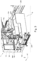
- Fig. 2 shows a schematic perspective view of a further lathe according to the prior art.
- the lathe shown comprises a machine frame designated as a whole by 10, which rises above a base surface 12 and has a machine bed 14 on which a first workpiece spindle 20 is held, which has a first workpiece holder 26.
- the first workpiece spindle 20 is assigned a rod feed device 30 with which a material rod 32 can be fed to the workpiece spindle 20 of the first workpiece holder 26 through a hollow shaft of a spindle motor 24.
- the first workpiece spindle 20 is assigned a first tool carrier 40 which comprises a rotatable turret head 44 in which a multiplicity of first tools 46 are arranged.
- the relative movement between the first tool 46A and the workpiece WR can be achieved, for example, in that the first tool carrier 40 sits on a slide system which, opposite the machine bed 14, is parallel to the first spindle axis 28 in a Z direction and perpendicular to the first spindle axis in an X direction.
- Direction is movable.
- a second workpiece spindle 50 which likewise has a second workpiece holder 56, is also arranged on the machine bed 14.
- the second workpiece holder 56 serves to hold the workpiece W processed on its front side V in the first workpiece spindle 20 with the Take up front V and edit on its back R.
- the second workpiece spindle 50 can be aligned coaxially to the first workpiece spindle 20 and can be moved in the direction of the first workpiece spindle 20.
- the second workpiece spindle 50 is held in a second spindle carrier, designated as a whole by 60, which can be displaced parallel to the Z direction via longitudinal guides 68, 70.
- the second workpiece spindle 50 can also be pivoted in the second spindle carrier 60 about a pivot axis 72 which runs perpendicular to a movement plane E which is spanned by the two directions X and Z.
- the second workpiece spindle 50 is from a position that is coaxial with the first workpiece spindle 20 into an in Fig. 2
- the position shown in phantom, in which the second workpiece receptacle 56 faces the base surface 12, can be pivoted.
- the position of the second workpiece spindle 50 shown in dash-dotted lines corresponds to an unloading position in which there is the possibility of transferring the workpiece W processed on the rear side R to a workpiece removal device 74.
- a second tool carrier 90 For machining the workpiece W on the rear side R in the second workpiece spindle 50, a second tool carrier 90 is provided which has a turret 94 on which second tools 96 are arranged.
- the second tool carrier 90 is also arranged on a second slide system 98, which is movable in the Z direction and in the X direction.
- Fig. 3 shows a schematic perspective view of a machine tool according to a first embodiment of the present invention.
- the machine tool 1 shown has a machine frame 110, a workpiece spindle 30 arranged on the machine frame 110 and having a workpiece holder 31 rotatable about a spindle axis S 1.
- the drive of the workpiece spindle 30 is designed as a direct drive.
- the machine tool 1 has a further workpiece spindle 120 arranged on the machine frame 110 with a further workpiece holder 121 rotatable about a further spindle axis S 2.
- the machining flow direction is in the viewing direction Fig. 3 left to right.
- the machine tool 1 For the supply of the workpieces W to be machined, the machine tool 1 has on the left in FIG Fig. 3 a shuttle 220, by means of which workpieces W to be processed automatically, in particular material bars and / or semi-finished products, are fed to the machine tool 1.
- a drag frame belt 230 On the right side of the machine tool 1, that is to say arranged downstream of the machine tool 1 in the machining flow direction, a drag frame belt 230 is provided for removing workpieces W machined by the machine tool 1.
- the machine tool 1 shown also has a pivoting device 10 according to the invention, which is provided to support the first workpiece spindle 30 in a rotatable or pivotable manner, the workpiece spindle 30 being pivotable in particular about a pivot axis Y 1 relative to a housing 1 of the pivoting device 10, the Pivot axis Y 1 is arranged parallel to a base G on which the machine tool 1 is set up.
- the workpiece spindle 30 is correspondingly in FIG Fig. 3 can be swiveled horizontally when viewed.
- the machine tool 1 has a first with at least one tool tool carrier 130 that can be equipped for machining a workpiece W held in the workpiece spindle 30 on one side V, in particular on a front side of the workpiece W, and a second tool carrier 140 that can be equipped with at least one tool for machining a workpiece W held in the further workpiece spindle 120 on another Side R, in particular on a rear side of the workpiece W.
- the first, pivotable workpiece spindle 30 together with the associated tool carrier 130 is arranged in front of the further workpiece spindle 120 with the associated tool carrier 140 in the machining flow direction.
- Fig. 3 an XYZ coordinate system is also specified, the X direction in Fig. 3 corresponds to a horizontal direction in the machining flow direction, the Y direction corresponds to a depth direction (in the viewing direction), and the Z direction corresponds to a vertical direction from bottom to top in Fig. 3 corresponds to.
- Fig. 4 shows a schematic perspective sectional view of a pivoting device according to an embodiment of the present invention.
- the pivoting device 10 shown has a housing 11 for attaching or fastening the pivoting device 10 to a machine tool 1, like the Fig. 3 can be removed, the housing 11 can be movably attached to the machine tool 1 by means of a guide device 160 of the pivoting device 10, in particular can be attached horizontally movably.
- the pivoting device 10 has a carrier device 20 for receiving the workpiece spindle 30 of the machine tool 1, which is rotatably mounted in or on the housing 11, whereby the workpiece spindle 30 is rotatably or pivotably mounted.
- the drive 12 for the pivoting and / or rotary movement of the carrier device 20 and thus the workpiece spindle 30 is designed as a direct drive which is provided in the housing 11.
- the rotary and / or swivel drive 12 is designed as a torque motor in a hollow shaft design, which sits directly on a hollow shaft 21 of the carrier device 20, which serves as the drive shaft of the torque motor.
- the hollow shaft 21 of the carrier device 20 is supported twice in the housing 11 and the torque motor is provided between the two bearing points which are arranged at two opposite ends of the housing 11.
- the workpiece spindle 30 can be rotated and / or pivoted about the aforementioned pivot axis Y 1.
- the carrier device 20 also has a spindle carrier 22 on which the workpiece spindle 30 is attached in such a way that the spindle axis S 1 of the workpiece holder 31, which can be rotatably driven about the spindle axis S 1 , is perpendicular to the pivot axis Y 1 .
- the spindle axis S 1 is oriented vertically, which corresponds to an initial position in which main machining operations can be carried out on the workpiece accommodated in the workpiece holder 31.
- main machining operations are understood to mean machining operations, in particular machining operations, which are carried out without inclining the workpiece spindle 30.
- FIG. 11 shows a schematic perspective view of the machine tool 1 according to the first embodiment in the state in which the first workpiece spindle 30 is brought into an inclined orientation by means of the pivoting device 10, in particular in FIG Fig. 5 viewed in a downward right-facing position. Due to the downward-facing position, the workpiece W received in the workpiece holder 31 can be machined by a tool that is received in the tool carrier 50, 130 arranged below the pivoting device 10 or below the workpiece spindle 30. As a result, an inclined workpiece machining of the workpiece W received in the workpiece spindle 30 is possible. In the in Fig. 5 In the illustrated state, an inclined hole is provided on the workpiece W. Among other things, drilling, turning, milling and grinding operations can be carried out on the workpiece W here.
- the swivel device 10 is also provided with a guide device 40, in particular a slide system, by means of which the workpiece spindle 30 is attached to the spindle carrier 22 in a displaceable or displaceable manner.
- a guide device 40 in particular a slide system
- the workpiece spindle 30 can be displaced parallel to the spindle axis S 1 of the workpiece spindle 30 and can thus be brought into a machining area of the first tool carrier 50, 130.
- Fig. 6 13 shows a schematic perspective view of the machine tool 1 according to the first embodiment in the state in which the partially machined workpiece W is transferred by the first workpiece spindle 30 to the second workpiece spindle 120 in order to enable the rear side of the workpiece W to be machined.
- the workpiece W can be reclamped and, on the other hand, an unnecessary tool change in the respective tool carriers 50, 130, 140 may be avoided.
- the tool spindle 30 can be infeed to the tool spindle 120 for workpiece transfer using the guide device 160 of the pivoting device 10 and / or the guide device 40 of the spindle carrier 22.
- the Fig. 5 can be removed, the guide device 160 of the pivoting device 10 and the guide device 170 of the second tool carrier 140 share the same guide rails 161, which are attached to the machine frame 110.
- the two tool carriers 130, 140 each have a turret head comprising a multiplicity of tool holders for holding tools, which can each be driven rotatably about a horizontal axis of rotation X 2 , X 3.
- the first tool carrier 50, 130 is arranged below the first workpiece spindle 30 and the second tool carrier 140 is arranged above the second workpiece spindle 120.
- Fig. 7 shows a schematic perspective view of a machine tool 1 according to a second embodiment of the present invention in the state in which a workpiece W held by the first and second workpiece spindles 30, 120 is supported by a steady rest 54 of a further tool carrier 50 in this case.
- the first tool carrier 130 and / or the second tool carrier 140 instead of a further tool carrier 50 as a tool carrier 50 with a steady rest 54.
- the further tool carrier 50 likewise has a turret head 51 comprising a multiplicity of tool receptacles 52 for receiving tools 53.
- a steady rest 54 is seated on the turret head 51, which steady rest is set up to hold the workpiece W received in the two workpiece spindles 30, 120 to support. This makes it possible for the workpiece W to be machined by the two workpiece carriers 140 while it is being supported by the steady rest 54. Thus, longer workpieces W or workpieces W with a smaller diameter can be machined without the machining quality being reduced by the influence of force during machining. This is achieved in particular by the opposite arrangement of the steady rest 54 and the second tool carrier 140.
- Fig. 7 can be further removed, the further tool carrier 50, whereby the machine tool 1 according to this embodiment has three tool carriers 50, 130, 140, sits below the second, stationary workpiece spindle 120.
- the further tool carrier can have a guide device 55, which, in the embodiment shown, is designed as a slide system by means of which the turret 51 can be moved parallel to the axis of rotation X 1 of the turret 51. In this way, the tool received in the further tool carrier 50 or the steady rest 54 can be moved along the longitudinal extension of the workpiece W in the X direction.
- the further tool carrier 50 has a further guide device 56, which is also designed as a slide system and by means of which the turret 51 can be moved perpendicular to the axis of rotation X1 of the turret 51 and thus perpendicular to the longitudinal extension of the workpiece W, in particular to the workpiece W. is employable.
- the further guide device 56 can carry out the infeed movement.
- axis of rotation X 1 of the turret 51 is parallel to a Axis of rotation S 1 -S 2 of a workpiece W that can be supported by steady rest 54 is formed.
- FIG. 11 shows a schematic perspective view of a machine tool 1 of a third embodiment of the present invention in the state in which a workpiece W received in the first workpiece spindle 30 is being machined with the aid of a milling and / or grinding device 150.
- the milling and / or grinding device 150 has a tool spindle 151 for milling and / or grinding. It is also possible to arrange the milling and / or grinding device 150 in the machine tool 1 in such a way that a workpiece W accommodated in the second workpiece spindle 120 can be machined by means of the milling and / or grinding device 150. In this case, by moving the first workpiece spindle 30, it may also be possible, by means of the one milling and / or grinding device 150, to machine workpieces that are received in one of the two workpiece spindles 30, 120.
- the milling and / or grinding device 150 has a guide device 155, which is designed as a slide system, by means of which the tool spindle 151 can be moved perpendicular to a spindle axis Z 1 of the tool spindle 151, the tool spindle 151 being preferred as shown is oriented vertically and the guide device 155 enables a movement parallel to the pivot axis Y 1 of the pivot device 10 in the Y direction.
- first and / or second tool carrier 130, 140 can also sit on a guide device 57, in particular a slide system, which enables a movement of the respective tool carrier 130, 140 allows in the Y direction.
- the workpiece W accommodated in the workpiece spindle 30 is to be machined by the milling and / or grinding device, then, as in FIG Fig. 8 is shown, with the aid of the swivel device 10, the guide device 40 of the spindle carrier 22 and the guide device 160 of the swivel device 10, the workpiece W received in the workpiece spindle 30 is brought into a machining area of the tool spindle 151.
- Fig. 9 shows a schematic perspective view of a machine tool 1 of a fourth embodiment of the present invention in the state in which a workpiece W received in the second workpiece spindle 120 is removed by means of a loading and / or unloading system, in particular a handling system 210.
- the illustrated handling system 210 has a first guide device 211 which is designed as a slide system which is arranged above a machining area of the machine tool 1, in particular above the first workpiece spindle 30 and above the second workpiece spindle 120, running horizontally in the X direction.
- a gripping device 212 is provided, which is set up to grip a workpiece W processed and / or to be processed by the first workpiece spindle 30 and / or the second workpiece spindle 120.
- the gripping device 212 has a gripper pivoting device, a gripper and gripping arms. Furthermore, a second guide device 213 is provided, which is also designed, for example, as a slide system, which is mounted on the first guide device 211 sits and the gripping device 212 carries.
- the gripping device 212 can be moved perpendicular to the X direction of the first guide device 213. In other words, using the first and second guide devices 211, 213, a 2-axis portal is created which enables the gripper to move in the Y-direction and Z-direction.
- Fig. 10 shows a schematic perspective view of the in Fig. 9 shown loading and / or unloading system in the state in which the removed workpiece W is to be placed on a dragging frame belt 230.
- the workpiece W has already been brought out of the machining area of the machine tool 1 by means of the two guide devices 211, 213 and positioned above the dragging frame belt 230.
- the gripping device 212 is moved vertically downwards in the direction of the dragging frame belt 230 by means of the second guide device 213, the workpiece W picked up is brought into a horizontal position by 90 degrees using the gripper pivoting device and then placed on the dragging frame belt 230.
- the gripping arms of the gripping device 212 are opened and the workpiece W is released.
- Fig. 11 shows a schematic perspective view of a further embodiment of the loading and unloading system in the state in which the machine tool 1 is loaded with workpieces W to be processed by means of a shuttle 220.
- Fig. 11 can be removed, to remove the workpiece to be processed from the shuttle 220, the workpiece spindle 30 is brought into a vertical orientation, the starting position, and by means of the guide device 160 of the pivoting device 30 and the guide device 40 of the spindle carrier 22 in a receiving position of the workpiece W above the Shuttle 220 will be brought.
- Fig. 12 shows a schematic perspective view of an alternative embodiment of the loading and unloading system in the state in which the machine tool 1 is loaded with workpieces W to be processed by means of a dragging frame belt 230.
Landscapes
- Engineering & Computer Science (AREA)
- Mechanical Engineering (AREA)
- Turning (AREA)
Applications Claiming Priority (1)
| Application Number | Priority Date | Filing Date | Title |
|---|---|---|---|
| DE102019209850.9A DE102019209850A1 (de) | 2019-07-04 | 2019-07-04 | Schwenkvorrichtung für Werkstückspindel einer Werkzeugmaschine, Werkzeugträger für eine Werkzeugmaschine und Werkzeugmaschine |
Publications (1)
| Publication Number | Publication Date |
|---|---|
| EP3795294A1 true EP3795294A1 (fr) | 2021-03-24 |
Family
ID=71515045
Family Applications (1)
| Application Number | Title | Priority Date | Filing Date |
|---|---|---|---|
| EP20184180.6A Pending EP3795294A1 (fr) | 2019-07-04 | 2020-07-06 | Dispositif pivotant pour broche de pièce d'une machine-outil, porte-outil pour machine-outil et machine-outil |
Country Status (2)
| Country | Link |
|---|---|
| EP (1) | EP3795294A1 (fr) |
| DE (1) | DE102019209850A1 (fr) |
Cited By (1)
| Publication number | Priority date | Publication date | Assignee | Title |
|---|---|---|---|---|
| CN114799233A (zh) * | 2022-04-18 | 2022-07-29 | 沈阳航天新光集团有限公司 | 一种过滤器的收口装置及收口方法 |
Citations (5)
| Publication number | Priority date | Publication date | Assignee | Title |
|---|---|---|---|---|
| DE19521846A1 (de) | 1995-06-16 | 1996-12-19 | Gildemeister Ag | Numerisch gesteuerte Bearbeitungsmaschine |
| DE19904859A1 (de) | 1999-02-05 | 2000-08-17 | Gildemeister Drehmaschinen Gmb | Drehmaschine mit zwei Werkstückspindeln |
| DE102004004019A1 (de) * | 2004-01-20 | 2005-08-11 | Index-Werke Gmbh & Co. Kg Hahn & Tessky | Drehmaschine |
| DE102011077571A1 (de) * | 2011-06-15 | 2012-12-20 | Gildemeister Italiana S.P.A. | Werkzeugmaschine |
| DE102012107295A1 (de) * | 2012-08-08 | 2014-02-13 | Index-Werke Gmbh & Co. Kg Hahn & Tessky | Werkzeugmaschine |
Family Cites Families (4)
| Publication number | Priority date | Publication date | Assignee | Title |
|---|---|---|---|---|
| DE102007031703A1 (de) * | 2007-07-06 | 2009-01-08 | Satisloh Gmbh | Maschine zur Bearbeitung von optischen Werkstücken, insbesondere von Kunststoff-Brillengläsern |
| DE102009013067A1 (de) * | 2009-03-16 | 2010-10-07 | Mag Europe Gmbh | Werkzeugmaschine und Verfahren zur Bearbeitung von Werkstücken |
| DE102015221719A1 (de) * | 2015-11-05 | 2017-05-11 | Emco Magdeburg Gmbh | Mittendrehaggregat und Vertikaldrehmaschine mit einem solchen Mittendrehaggregat |
| DE102016006791A1 (de) * | 2016-06-07 | 2017-12-07 | Satisloh Ag | Maschine zur Bearbeitung von Werkstücken in optischer Qualität |
-
2019
- 2019-07-04 DE DE102019209850.9A patent/DE102019209850A1/de active Pending
-
2020
- 2020-07-06 EP EP20184180.6A patent/EP3795294A1/fr active Pending
Patent Citations (6)
| Publication number | Priority date | Publication date | Assignee | Title |
|---|---|---|---|---|
| DE19521846A1 (de) | 1995-06-16 | 1996-12-19 | Gildemeister Ag | Numerisch gesteuerte Bearbeitungsmaschine |
| DE19904859A1 (de) | 1999-02-05 | 2000-08-17 | Gildemeister Drehmaschinen Gmb | Drehmaschine mit zwei Werkstückspindeln |
| DE102004004019A1 (de) * | 2004-01-20 | 2005-08-11 | Index-Werke Gmbh & Co. Kg Hahn & Tessky | Drehmaschine |
| DE102004004019B4 (de) | 2004-01-20 | 2008-04-10 | Index-Werke Gmbh & Co. Kg Hahn & Tessky | Drehmaschine |
| DE102011077571A1 (de) * | 2011-06-15 | 2012-12-20 | Gildemeister Italiana S.P.A. | Werkzeugmaschine |
| DE102012107295A1 (de) * | 2012-08-08 | 2014-02-13 | Index-Werke Gmbh & Co. Kg Hahn & Tessky | Werkzeugmaschine |
Cited By (2)
| Publication number | Priority date | Publication date | Assignee | Title |
|---|---|---|---|---|
| CN114799233A (zh) * | 2022-04-18 | 2022-07-29 | 沈阳航天新光集团有限公司 | 一种过滤器的收口装置及收口方法 |
| CN114799233B (zh) * | 2022-04-18 | 2023-10-20 | 沈阳航天新光集团有限公司 | 一种过滤器的收口装置及收口方法 |
Also Published As
| Publication number | Publication date |
|---|---|
| DE102019209850A1 (de) | 2021-01-07 |
Similar Documents
| Publication | Publication Date | Title |
|---|---|---|
| DE3035451C2 (fr) | ||
| DE69907283T2 (de) | Maschine zum bohren von öllöchern in kurbelwellen und dessen methode | |
| DE10029749C2 (de) | Vorrichtung und Verfahren zum Beschicken und/oder Entnehmen von Werkstücken an einer Werkzeugmaschine | |
| EP1418019B2 (fr) | Machine-outil avec au moins deux tourettes revolver à outils, comprenant chacune un dispositif porte-pièce | |
| EP1634676B1 (fr) | Tour vertical | |
| EP3641972B1 (fr) | Systeme de déplacement et machine à tailler les engrenages | |
| CH695442A5 (de) | Verfahren und Vorrichtung zur Rundum-Bearbeitung eines Rohlings in einer Fräsmaschine. | |
| DE2853949A1 (de) | Be- und entladeeinrichtung fuer werkzeugmaschinen | |
| EP1260307A2 (fr) | Machine-outil et procédé d'usinage d'une pièce en forme de barre | |
| EP0885686A1 (fr) | Centre d'usinage | |
| DE2904088A1 (de) | Be- und/oder entladeeinrichtung fuer werkzeugmaschinen, insbesondere drehautomaten | |
| EP1712329B1 (fr) | Ligne de production avec système de charge et transport de pièce | |
| EP0130309B1 (fr) | Machines à travailler le bois | |
| EP1651381B1 (fr) | Machine-outil avec systeme de fixation des deux cotes | |
| DE10311762A1 (de) | Vertikal-Bearbeitungszentrum | |
| DE4022458C2 (fr) | ||
| EP3795294A1 (fr) | Dispositif pivotant pour broche de pièce d'une machine-outil, porte-outil pour machine-outil et machine-outil | |
| EP1647358A1 (fr) | Machine de traitement plusieurs faces de la pièce et dispositif pour le positionnement de la pièce | |
| DE10025614A1 (de) | Vorrichtung zum Greifen und Transportieren von Werkstücken in Drehmaschinen | |
| EP0913226B1 (fr) | Centre d'usinage dans lequel les porte-pièces sont pourvus d'un module de couplage ainsi que d'une connexion multiple | |
| DE102017127116B4 (de) | Werkzeugmaschine, Fertigungszelle sowie Verfahren zum Betreiben einer Fertigungszelle | |
| DE102008045069B4 (de) | Vertikalbearbeitungsmaschine mit Werkzeugeinheit und Verfahren hierfür | |
| EP3159102B1 (fr) | Machine-outil avec dispositif de commande et procédé pour machine-outil | |
| EP0637277B1 (fr) | Dispositif pour l'usinage de metaux par enlevement de copeaux | |
| EP2161099B1 (fr) | Affûteuse |
Legal Events
| Date | Code | Title | Description |
|---|---|---|---|
| PUAI | Public reference made under article 153(3) epc to a published international application that has entered the european phase |
Free format text: ORIGINAL CODE: 0009012 |
|
| STAA | Information on the status of an ep patent application or granted ep patent |
Free format text: STATUS: THE APPLICATION HAS BEEN PUBLISHED |
|
| AK | Designated contracting states |
Kind code of ref document: A1 Designated state(s): AL AT BE BG CH CY CZ DE DK EE ES FI FR GB GR HR HU IE IS IT LI LT LU LV MC MK MT NL NO PL PT RO RS SE SI SK SM TR |
|
| AX | Request for extension of the european patent |
Extension state: BA ME |
|
| STAA | Information on the status of an ep patent application or granted ep patent |
Free format text: STATUS: REQUEST FOR EXAMINATION WAS MADE |
|
| 17P | Request for examination filed |
Effective date: 20210426 |
|
| RBV | Designated contracting states (corrected) |
Designated state(s): AL AT BE BG CH CY CZ DE DK EE ES FI FR GB GR HR HU IE IS IT LI LT LU LV MC MK MT NL NO PL PT RO RS SE SI SK SM TR |
|
| STAA | Information on the status of an ep patent application or granted ep patent |
Free format text: STATUS: EXAMINATION IS IN PROGRESS |
|
| 17Q | First examination report despatched |
Effective date: 20230704 |
|
| STAA | Information on the status of an ep patent application or granted ep patent |
Free format text: STATUS: THE APPLICATION IS DEEMED TO BE WITHDRAWN |