EP3795294A1 - Machine tool; pivoting device for workpiece spindle of a machine tool and tool holder for a machine tool - Google Patents
Machine tool; pivoting device for workpiece spindle of a machine tool and tool holder for a machine tool Download PDFInfo
- Publication number
- EP3795294A1 EP3795294A1 EP20184180.6A EP20184180A EP3795294A1 EP 3795294 A1 EP3795294 A1 EP 3795294A1 EP 20184180 A EP20184180 A EP 20184180A EP 3795294 A1 EP3795294 A1 EP 3795294A1
- Authority
- EP
- European Patent Office
- Prior art keywords
- workpiece
- spindle
- tool
- machine tool
- workpiece spindle
- Prior art date
- Legal status (The legal status is an assumption and is not a legal conclusion. Google has not performed a legal analysis and makes no representation as to the accuracy of the status listed.)
- Pending
Links
Images


Classifications
-
- B—PERFORMING OPERATIONS; TRANSPORTING
- B23—MACHINE TOOLS; METAL-WORKING NOT OTHERWISE PROVIDED FOR
- B23Q—DETAILS, COMPONENTS, OR ACCESSORIES FOR MACHINE TOOLS, e.g. ARRANGEMENTS FOR COPYING OR CONTROLLING; MACHINE TOOLS IN GENERAL CHARACTERISED BY THE CONSTRUCTION OF PARTICULAR DETAILS OR COMPONENTS; COMBINATIONS OR ASSOCIATIONS OF METAL-WORKING MACHINES, NOT DIRECTED TO A PARTICULAR RESULT
- B23Q39/00—Metal-working machines incorporating a plurality of sub-assemblies, each capable of performing a metal-working operation
- B23Q39/04—Metal-working machines incorporating a plurality of sub-assemblies, each capable of performing a metal-working operation the sub-assemblies being arranged to operate simultaneously at different stations, e.g. with an annular work-table moved in steps
- B23Q39/048—Metal-working machines incorporating a plurality of sub-assemblies, each capable of performing a metal-working operation the sub-assemblies being arranged to operate simultaneously at different stations, e.g. with an annular work-table moved in steps the work holder of a work station transfers directly its workpiece to the work holder of a following work station
-
- B—PERFORMING OPERATIONS; TRANSPORTING
- B23—MACHINE TOOLS; METAL-WORKING NOT OTHERWISE PROVIDED FOR
- B23Q—DETAILS, COMPONENTS, OR ACCESSORIES FOR MACHINE TOOLS, e.g. ARRANGEMENTS FOR COPYING OR CONTROLLING; MACHINE TOOLS IN GENERAL CHARACTERISED BY THE CONSTRUCTION OF PARTICULAR DETAILS OR COMPONENTS; COMBINATIONS OR ASSOCIATIONS OF METAL-WORKING MACHINES, NOT DIRECTED TO A PARTICULAR RESULT
- B23Q1/00—Members which are comprised in the general build-up of a form of machine, particularly relatively large fixed members
- B23Q1/25—Movable or adjustable work or tool supports
- B23Q1/44—Movable or adjustable work or tool supports using particular mechanisms
- B23Q1/50—Movable or adjustable work or tool supports using particular mechanisms with rotating pairs only, the rotating pairs being the first two elements of the mechanism
- B23Q1/52—Movable or adjustable work or tool supports using particular mechanisms with rotating pairs only, the rotating pairs being the first two elements of the mechanism a single rotating pair
-
- B—PERFORMING OPERATIONS; TRANSPORTING
- B23—MACHINE TOOLS; METAL-WORKING NOT OTHERWISE PROVIDED FOR
- B23B—TURNING; BORING
- B23B3/00—General-purpose turning-machines or devices, e.g. centre lathes with feed rod and lead screw; Sets of turning-machines
- B23B3/30—Turning-machines with two or more working-spindles, e.g. in fixed arrangement
-
- B—PERFORMING OPERATIONS; TRANSPORTING
- B23—MACHINE TOOLS; METAL-WORKING NOT OTHERWISE PROVIDED FOR
- B23Q—DETAILS, COMPONENTS, OR ACCESSORIES FOR MACHINE TOOLS, e.g. ARRANGEMENTS FOR COPYING OR CONTROLLING; MACHINE TOOLS IN GENERAL CHARACTERISED BY THE CONSTRUCTION OF PARTICULAR DETAILS OR COMPONENTS; COMBINATIONS OR ASSOCIATIONS OF METAL-WORKING MACHINES, NOT DIRECTED TO A PARTICULAR RESULT
- B23Q2210/00—Machine tools incorporating a specific component
- B23Q2210/004—Torque motors
-
- B—PERFORMING OPERATIONS; TRANSPORTING
- B23—MACHINE TOOLS; METAL-WORKING NOT OTHERWISE PROVIDED FOR
- B23Q—DETAILS, COMPONENTS, OR ACCESSORIES FOR MACHINE TOOLS, e.g. ARRANGEMENTS FOR COPYING OR CONTROLLING; MACHINE TOOLS IN GENERAL CHARACTERISED BY THE CONSTRUCTION OF PARTICULAR DETAILS OR COMPONENTS; COMBINATIONS OR ASSOCIATIONS OF METAL-WORKING MACHINES, NOT DIRECTED TO A PARTICULAR RESULT
- B23Q2220/00—Machine tool components
- B23Q2220/006—Spindle heads
-
- B—PERFORMING OPERATIONS; TRANSPORTING
- B23—MACHINE TOOLS; METAL-WORKING NOT OTHERWISE PROVIDED FOR
- B23Q—DETAILS, COMPONENTS, OR ACCESSORIES FOR MACHINE TOOLS, e.g. ARRANGEMENTS FOR COPYING OR CONTROLLING; MACHINE TOOLS IN GENERAL CHARACTERISED BY THE CONSTRUCTION OF PARTICULAR DETAILS OR COMPONENTS; COMBINATIONS OR ASSOCIATIONS OF METAL-WORKING MACHINES, NOT DIRECTED TO A PARTICULAR RESULT
- B23Q2707/00—Automatic supply or removal of metal workpieces
- B23Q2707/003—Automatic supply or removal of metal workpieces in a lathe
Definitions
- the present invention relates to a swivel device for a workpiece spindle of a machine tool, a tool carrier for a machine tool and a machine tool for machining workpieces, in particular bar material.
- the present invention also relates to a loading and unloading system for a machine tool for supplying workpieces to be machined and / or removing workpieces machined by the machine tool.
- Machine tools for machining workpieces are known in which both ends of the workpiece can be machined in one machine tool, i.e. two-sided machining of the workpiece can be carried out.
- a lathe of this type described is mounted in each of two headstocks so that a workpiece spindle can be driven in a rotating manner.
- Each headstock carries a tool holder on the side opposite the workpiece spindle.
- the tools received therein are used to machine the workpiece clamped on the workpiece spindle of the other headstock.
- the workpiece is picked up in the vertical alignment of the first workpiece spindle by its workpiece clamping device from a horizontal support, after this first workpiece spindle has been swiveled into the horizontal, it is processed by the tools that sit in the tool holder of the second headstock and then transferred to the chuck of the second workpiece spindle.
- the second side of the workpiece is then machined by the tools provided on the first headstock and, after pivoting the second workpiece spindle into the vertical position, placed on a workpiece support surface.
- each headstock carries both a workpiece spindle and tools, and both headstocks are involved in the machining process during machining, only one workpiece can be machined during the machining time and no other workpiece can be handled during this time.
- the time from picking up an initial workpiece to depositing a completely machined workpiece is therefore comparatively long and the throughput of such lathes is rather low.
- horizontal supports for workpieces are provided below the workpiece clamping means, which can be pivoted vertically downwards with the workpiece spindles, the workpiece spindles for machining the workpieces held in the workpiece clamping means being designed in a hanging arrangement with a vertical axis of rotation and a tool holder being arranged below the hanging workpiece clamping means on the machine bed.
- the second workpiece spindle can be pivoted about a pivot axis running transversely to the second spindle axis, namely from a position in which the second spindle axis runs parallel or coaxially to the first spindle axis to a position in which the second spindle axis is transverse to the first Spindle axis is aligned.
- first tool carrier equipped with at least one tool for machining a workpiece held in the first workpiece spindle on one side
- a second tool carrier equipped with at least one tool for machining a workpiece held in the second workpiece spindle on the other side.
- the first and second workpiece spindles with facing workpiece holders can be moved into a transfer position of the workpiece spindles for the direct transfer of the workpiece machined on one side from one of the workpiece holders to the other workpiece holder.
- the spindle axes are aligned coaxially to one another and in Movable in the direction of the axes, wherein the first workpiece spindle for loading the raw workpiece is assigned a bar feeder.
- the finished workpiece can be transferred from the second workpiece spindle with the second spindle axis running transversely to the first spindle axis to a workpiece removal device.
- the lathe described has the problem, however, that when the workpiece is delivered by the second workpiece spindle to the downstream workpiece removal device, the workpiece can only be positioned imprecisely on the workpiece removal device, in particular a carrier element of the workpiece removal device, whereby the position in the lathe and alignment information about the workpiece is lost when it is transferred to the workpiece removal device.
- the invention is based on the object of providing a machine tool that is capable of overlapping machining and handling operations on the one hand in order to minimize the time from picking up an initial workpiece to depositing a completely machined workpiece, and on the other hand, inclined machining on an in To perform a workpiece recorded on a workpiece spindle with high precision and a high degree of freedom. Furthermore, the provided machine tool should be able to carry out milling work with high cutting forces and to make the position and orientation information about the machined workpiece available for downstream machining steps and at the same time to realize a compact and inherently rigid construction in order to avoid unnecessary vibrations that could impair the machining result.
- a swivel device for a workpiece spindle of a machine tool in particular a lathe, according to claim 1.
- the invention provides a tool carrier for a machine tool, in particular a lathe, according to claim 10 and a machine tool, in particular lathe, according to claim 13.
- the present invention also relates to a loading and unloading system for a machine tool for supplying workpieces to be machined and / or removing workpieces machined by the machine tool.
- One of the core ideas of the present invention is a swivel device for a workpiece spindle to provide a machine tool in which the pivoting movement and / or rotary movement is driven by a torque motor or a master-slave gear drive, whereby a high position accuracy and a high drive torque or holding torque can be provided for the pivoting device and the workpiece spindle can be brought into any desired angular position and can be fixed in this.
- a workpiece spindle can be provided which enables an inclined workpiece machining of a workpiece held in the workpiece spindle.
- Due to the very high holding torque provided by the torque motor, a machine tool equipped with the pivoting device according to the invention is capable of machining workpieces, in particular milling work, with extremely high cutting forces.
- a swivel device for a workpiece spindle of a machine tool in particular a lathe, for machining a workpiece, in particular bar material, which is preferably at least partially made of metal or the like, has: a housing for attaching the swivel device to a machine tool , a carrier device for receiving a workpiece spindle of the machine tool, which is rotatably mounted in the housing, and a drive provided on the housing, in particular in the housing, for driving a pivoting and / or rotary movement of the carrier device about a pivot axis relative to the housing, the drive is a torque motor or a master-slave gear drive.
- a safety axis with fixation can be provided, which enables a work piece spindle to be swiveled continuously about a desired swivel axis.
- the swivel output as a torque motor and / or master-slave gear drive
- a high torque can be achieved with a high holding torque at the same time.
- the infinitely variable pivoting of the workpiece spindle makes it possible to carry out machining operations, in particular machining operations, in any angular or inclined position on the workpiece held in the workpiece spindle. This means that special tools can be avoided and machining in undercuts can be carried out without special tools.
- the high holding torque provided enables workpiece machining, in particular milling work, to be carried out with extremely high cutting forces.
- the torque motor is a motor with a holding torque of more than 100 Nm and is preferably designed as a direct drive, and / or the drive is set up to use a step angle of ⁇ 50 angular seconds, preferably ⁇ 10 angular seconds, more preferably ⁇ 50 arc seconds to be realized.
- the torque motor is preferably designed as a synchronous motor with a maximum torque in the range from 200 to 400 Nm and a speed in the range from 0 to 5000 rpm.
- the master-slave gear drive consists of two drives, a master drive and a slave drive, which are also preferably designed as synchronous motors, and both are operatively connected to a common drive shaft via a gear drive.
- the two drives each have a drive pinion that would come with a main gear that is attached to the drive shaft.
- the carrier device has a hollow shaft which serves as the drive shaft of the torque motor or the master-slave gear drive.
- the torque motor is designed as a central rotary drive so that both ends of a / the drive shaft are exposed, the two ends of the drive shaft preferably being rotatably mounted in the housing.
- the carrier device has a spindle carrier to which the workpiece spindle is attached in such a way that a spindle axis of a workpiece holder, which is rotatable about the spindle axis, is transverse, in particular perpendicular, to the pivot axis.
- the workpiece spindle is mounted on the spindle carrier so as to be displaceable parallel to the spindle axis by means of a guide device, in particular a slide system.
- the workpiece spindle can be rotated or pivoted about an initial position by means of the pivoting device at least by an angle of ⁇ 50 °, in particular at least by an angle of ⁇ 95 °, the initial position preferably being a vertical position of the workpiece spindle.
- the pivoting device has a clamping device, in particular a safety clamping device, which is preferably pneumatic or is hydraulically actuated.
- the safety clamping device is to be understood as meaning that the clamping device is closed in a non-actuated state, that is to say in a clamping state, and is only released by actuation, in particular by applying a pneumatic or hydraulic pressure. This can ensure that the pivot axis is clamped in the event of a fault or emergency.
- the clamping device it is possible to clamp the swivel device, in particular the workpiece spindle, steplessly, whereby a fixation with an even greater holding torque is realized.
- the swivel device has a measuring system, in particular an inductive angle measuring device. It is preferred here that the measuring system has a measuring accuracy of up to ⁇ 1 angular second.
- the pivoting device can be positioned and fixed with a very high degree of angular accuracy, as a result of which machining operations can be carried out in any angular position on the workpiece held in the pivoting device, in particular in the workpiece spindle which is attached to the pivoting device.
- a main bearing of the torque motor which is preferably arranged on the side of the drive shaft facing the carrier device, is designed as an axial / radial bearing, in particular a YRTC bearing.
- the measuring system is designed in the vicinity of the main bearing, as a result of which possible angle errors due to torsional stresses on the drive shaft can be reduced.
- the present invention further relates to a tool carrier for a machine tool, in particular a lathe, more preferably the one described below Machine tool according to the present invention, for machining a workpiece, in particular bar material, which is preferably formed at least in sections from metal or the like, comprising: a turret head comprising a plurality of tool holders for holding tools and a steady rest which is set up to hold workpieces, which are processed in a machine tool provided with the tool carrier.
- a tool carrier can be provided which enables a machine tool in which it is provided or installed to additionally support workpieces that are received in one or in two workpiece spindles, in particular their workpiece holders. This makes it possible to machine longer workpieces or workpieces with a smaller diameter without reducing the machining quality due to undesired displacements of the workpiece during machining.
- the tool carrier has a guide device, in particular a slide system, by means of which the turret head can be moved parallel to an axis of rotation of the turret head and / or a further guide device, in particular a slide system, by means of which the turret head is transverse, in particular perpendicular, to the axis of rotation of the Turret head is movable, has.
- the axis of rotation of the turret head is parallel to an axis of rotation of a workpiece that can be supported by the steady rest.
- the present invention further relates to a machine tool, in particular a lathe, for machining a workpiece, in particular bar material, which is preferably formed at least in sections from metal or the like, comprising: a Machine frame, a workpiece spindle arranged on the machine frame with a workpiece holder that can be rotated about a spindle axis, another workpiece spindle arranged on the machine frame with another workpiece holder that can be rotated about another spindle axis, a first tool carrier that can be equipped with at least one tool for machining a workpiece held in the workpiece spindle on one side , and a swivel device for swiveling and / or rotating the workpiece spindle about a swivel axis which is aligned approximately parallel to a base area on which the machine frame is set up, the workpiece spindle being steplessly reversed by means of the swivel device, in particular the swivel device according to the invention described above an initial position
- the workpiece spindle can be rotated or pivoted about an initial position by means of the pivoting device at least through an angle of ⁇ 50 °, in particular at least through an angle of ⁇ 95 °, the initial position preferably being a vertical position of the workpiece spindle.
- the pivotable workpiece spindle is arranged in front of or behind the further workpiece spindle in the machining flow direction.
- the machine tool furthermore has a second tool carrier that can be equipped with at least one tool for machining a workpiece held in the further workpiece spindle on another side, in particular the rear, with the first tool carrier and / or the second tool carrier preferably being the one above described tool carrier according to the invention is / are.
- the machine tool has a milling and / or grinding device with a tool spindle for milling and / or grinding a workpiece held in the workpiece spindle and / or in the further workpiece spindle.
- the milling and / or grinding device also has a guide device, in particular a slide system, by means of which the tool spindle can be moved transversely, in particular perpendicularly, to a spindle axis of the tool spindle, the tool spindle preferably being oriented vertically and the guide device moving enables parallel to the pivot axis of the pivoting device in a so-called Y-direction.
- a guide device in particular a slide system
- the swivel device and / or the guide device are set up in such a way that a workpiece held in the workpiece spindle can be brought into a machining area of the tool spindle, with the spindle axis of the tool spindle in particular in an oblique orientation with respect to the spindle axis of the tool spindle can be brought.
- the first tool carrier and / or the second tool carrier also has a guide device, in particular a slide system, by means of which a / the turret of the tool holder can be moved transversely, in particular perpendicularly, to the respective spindle axis, the guide device preferably moving in parallel allows for the pivot axis of the pivot device in a so-called Y direction.
- a guide device in particular a slide system, by means of which a / the turret of the tool holder can be moved transversely, in particular perpendicularly, to the respective spindle axis, the guide device preferably moving in parallel allows for the pivot axis of the pivot device in a so-called Y direction.
- first workpiece spindle and / or the second workpiece spindle is / are designed as a direct drive with a hollow shaft, in which the unmachined workpiece is preferably driven by a Hollow shaft of the direct drive can be fed to the workpiece holder.
- the first workpiece spindle and / or the second workpiece spindle is assigned a bar feed device, in particular a bar loader, with which a material bar can be fed through the hollow shaft of the direct drive to the workpiece holder.
- the machine tool has a further guide device, in particular a slide system, on which the swivel device sits and by means of which the swivel device can be moved transversely, in particular perpendicularly, to the swivel axis, in particular a movement in a so-called X direction is enabled.
- a further guide device in particular a slide system, on which the swivel device sits and by means of which the swivel device can be moved transversely, in particular perpendicularly, to the swivel axis, in particular a movement in a so-called X direction is enabled.
- the machine tool has a further guide device, in particular a slide system, on which the second tool carrier sits and can be moved parallel to the spindle axis of the second workpiece spindle, the guide device of the swivel device and the guide device of the second tool carrier preferably using common guide rails .
- the machine tool has a loading and / or unloading system
- the loading and unloading system has at least one handling system, a shuttle, a drag frame belt, a pallet belt and / or a robot
- the loading and / or Unloading system is preferably provided for loading the machine tool with material bars and / or semi-finished products and / or blanks and / or for unloading machined workpieces or partially machined or finished workpieces. It is preferably the loading and unloading system around the loading and / or unloading system according to the invention described below.
- the present invention relates to a loading and / or unloading system, comprising: at least one handling system, a shuttle, a drag frame belt, a pallet belt and / or a robot, the loading and / or unloading system preferably for loading the machine tool with material bars and / or semi-finished products and / or blanks and / or for unloading machined workpieces or partially machined or finished workpieces.
- the handling system of the loading and / or unloading system has a first guide device, in particular a slide system, which is positioned horizontally above a machining area of the machine tool, in particular above the first workpiece spindle and / or the second workpiece spindle of the machine tool, in particular in a so-called X-direction, a gripping device, which is set up to grip a workpiece machined and / or to be machined by the first workpiece spindle and / or the second workpiece spindle, and a second guide device, in particular a slide system, which on the first guide device sits and carries the gripping device, wherein the gripping device can be moved transversely, in particular perpendicularly, to the X-direction of the first guide device, in particular a movement is made possible vertically in a so-called Z-direction.
- a first guide device in particular a slide system, which is positioned horizontally above a machining area of the machine tool, in particular above the first workpiece
- the gripping device has a gripper pivoting device by means of which the gripper can be pivoted about a horizontal pivot axis, in particular pivotable through an angle of ⁇ 90 degrees.
- the dragging frame belt for the supply / removal of workpieces to / from a Machine tool, having a chain drive with a revolving chain for the transport of a large number of dragging frames, which revolve endlessly on an upper side of the dragging frame belt, and a lifting table which is set up in a storage / pick-up direction of the workpieces to be transported, which is perpendicular to a base area , on which the towing frame belt stands, to be movably mounted.
- the lifting table has a movable body and a base plate firmly connected to the dragging frame belt, the movable body against adjustable stop screws, preferably four countersunk screws, via at least two pressure springs, preferably four pressure springs, which are attached to the base plate, which serve as a stop for the movable body, is pressed, whereby the movable body can be positioned and fixed in an upper position.
- a base plate of the movable body has four bores, in particular countersunk bores, through which the adjustable stop screws protrude, whereby the movable body is guided transversely to its direction of movement, which corresponds to the storage / pick-up direction of the workpieces.
- the lifting table is set up in such a way that a workpiece support surface of the lifting table, which is an upper side of the movable body, can be aligned approximately level with the upper side of the dragging frame belt, the alignment being able to be carried out using the adjustable stop screws.
- the lifting table has a pressure monitoring device, by means of which a pressure path in the direction of the direction of movement of the movable body runs, can be monitored, the monitoring is preferably carried out by means of two Hall sensors.
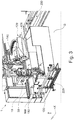
- Fig. 1 shows a schematic perspective view of a lathe according to the prior art.
- the lathe shown has a machine bed 1 and two workpiece spindles 5 and 6.
- the machine bed 1 is designed as a frame, which carries bed guides 1b on its upper side.
- the bed slides 2 carry cross slides 3, on which longitudinal slides 4 are in turn guided.
- Pivoting mounts 5d and 6d are pivotably attached to the longitudinal slide 4 and each carry a workpiece spindle 5 and 6 designed as an integrated motor spindle.
- Fig. 2 shows a schematic perspective view of a further lathe according to the prior art.
- the lathe shown comprises a machine frame designated as a whole by 10, which rises above a base surface 12 and has a machine bed 14 on which a first workpiece spindle 20 is held, which has a first workpiece holder 26.
- the first workpiece spindle 20 is assigned a rod feed device 30 with which a material rod 32 can be fed to the workpiece spindle 20 of the first workpiece holder 26 through a hollow shaft of a spindle motor 24.
- the first workpiece spindle 20 is assigned a first tool carrier 40 which comprises a rotatable turret head 44 in which a multiplicity of first tools 46 are arranged.
- the relative movement between the first tool 46A and the workpiece WR can be achieved, for example, in that the first tool carrier 40 sits on a slide system which, opposite the machine bed 14, is parallel to the first spindle axis 28 in a Z direction and perpendicular to the first spindle axis in an X direction.
- Direction is movable.
- a second workpiece spindle 50 which likewise has a second workpiece holder 56, is also arranged on the machine bed 14.
- the second workpiece holder 56 serves to hold the workpiece W processed on its front side V in the first workpiece spindle 20 with the Take up front V and edit on its back R.
- the second workpiece spindle 50 can be aligned coaxially to the first workpiece spindle 20 and can be moved in the direction of the first workpiece spindle 20.
- the second workpiece spindle 50 is held in a second spindle carrier, designated as a whole by 60, which can be displaced parallel to the Z direction via longitudinal guides 68, 70.
- the second workpiece spindle 50 can also be pivoted in the second spindle carrier 60 about a pivot axis 72 which runs perpendicular to a movement plane E which is spanned by the two directions X and Z.
- the second workpiece spindle 50 is from a position that is coaxial with the first workpiece spindle 20 into an in Fig. 2
- the position shown in phantom, in which the second workpiece receptacle 56 faces the base surface 12, can be pivoted.
- the position of the second workpiece spindle 50 shown in dash-dotted lines corresponds to an unloading position in which there is the possibility of transferring the workpiece W processed on the rear side R to a workpiece removal device 74.
- a second tool carrier 90 For machining the workpiece W on the rear side R in the second workpiece spindle 50, a second tool carrier 90 is provided which has a turret 94 on which second tools 96 are arranged.
- the second tool carrier 90 is also arranged on a second slide system 98, which is movable in the Z direction and in the X direction.
- Fig. 3 shows a schematic perspective view of a machine tool according to a first embodiment of the present invention.
- the machine tool 1 shown has a machine frame 110, a workpiece spindle 30 arranged on the machine frame 110 and having a workpiece holder 31 rotatable about a spindle axis S 1.
- the drive of the workpiece spindle 30 is designed as a direct drive.
- the machine tool 1 has a further workpiece spindle 120 arranged on the machine frame 110 with a further workpiece holder 121 rotatable about a further spindle axis S 2.
- the machining flow direction is in the viewing direction Fig. 3 left to right.
- the machine tool 1 For the supply of the workpieces W to be machined, the machine tool 1 has on the left in FIG Fig. 3 a shuttle 220, by means of which workpieces W to be processed automatically, in particular material bars and / or semi-finished products, are fed to the machine tool 1.
- a drag frame belt 230 On the right side of the machine tool 1, that is to say arranged downstream of the machine tool 1 in the machining flow direction, a drag frame belt 230 is provided for removing workpieces W machined by the machine tool 1.
- the machine tool 1 shown also has a pivoting device 10 according to the invention, which is provided to support the first workpiece spindle 30 in a rotatable or pivotable manner, the workpiece spindle 30 being pivotable in particular about a pivot axis Y 1 relative to a housing 1 of the pivoting device 10, the Pivot axis Y 1 is arranged parallel to a base G on which the machine tool 1 is set up.
- the workpiece spindle 30 is correspondingly in FIG Fig. 3 can be swiveled horizontally when viewed.
- the machine tool 1 has a first with at least one tool tool carrier 130 that can be equipped for machining a workpiece W held in the workpiece spindle 30 on one side V, in particular on a front side of the workpiece W, and a second tool carrier 140 that can be equipped with at least one tool for machining a workpiece W held in the further workpiece spindle 120 on another Side R, in particular on a rear side of the workpiece W.
- the first, pivotable workpiece spindle 30 together with the associated tool carrier 130 is arranged in front of the further workpiece spindle 120 with the associated tool carrier 140 in the machining flow direction.
- Fig. 3 an XYZ coordinate system is also specified, the X direction in Fig. 3 corresponds to a horizontal direction in the machining flow direction, the Y direction corresponds to a depth direction (in the viewing direction), and the Z direction corresponds to a vertical direction from bottom to top in Fig. 3 corresponds to.
- Fig. 4 shows a schematic perspective sectional view of a pivoting device according to an embodiment of the present invention.
- the pivoting device 10 shown has a housing 11 for attaching or fastening the pivoting device 10 to a machine tool 1, like the Fig. 3 can be removed, the housing 11 can be movably attached to the machine tool 1 by means of a guide device 160 of the pivoting device 10, in particular can be attached horizontally movably.
- the pivoting device 10 has a carrier device 20 for receiving the workpiece spindle 30 of the machine tool 1, which is rotatably mounted in or on the housing 11, whereby the workpiece spindle 30 is rotatably or pivotably mounted.
- the drive 12 for the pivoting and / or rotary movement of the carrier device 20 and thus the workpiece spindle 30 is designed as a direct drive which is provided in the housing 11.
- the rotary and / or swivel drive 12 is designed as a torque motor in a hollow shaft design, which sits directly on a hollow shaft 21 of the carrier device 20, which serves as the drive shaft of the torque motor.
- the hollow shaft 21 of the carrier device 20 is supported twice in the housing 11 and the torque motor is provided between the two bearing points which are arranged at two opposite ends of the housing 11.
- the workpiece spindle 30 can be rotated and / or pivoted about the aforementioned pivot axis Y 1.
- the carrier device 20 also has a spindle carrier 22 on which the workpiece spindle 30 is attached in such a way that the spindle axis S 1 of the workpiece holder 31, which can be rotatably driven about the spindle axis S 1 , is perpendicular to the pivot axis Y 1 .
- the spindle axis S 1 is oriented vertically, which corresponds to an initial position in which main machining operations can be carried out on the workpiece accommodated in the workpiece holder 31.
- main machining operations are understood to mean machining operations, in particular machining operations, which are carried out without inclining the workpiece spindle 30.
- FIG. 11 shows a schematic perspective view of the machine tool 1 according to the first embodiment in the state in which the first workpiece spindle 30 is brought into an inclined orientation by means of the pivoting device 10, in particular in FIG Fig. 5 viewed in a downward right-facing position. Due to the downward-facing position, the workpiece W received in the workpiece holder 31 can be machined by a tool that is received in the tool carrier 50, 130 arranged below the pivoting device 10 or below the workpiece spindle 30. As a result, an inclined workpiece machining of the workpiece W received in the workpiece spindle 30 is possible. In the in Fig. 5 In the illustrated state, an inclined hole is provided on the workpiece W. Among other things, drilling, turning, milling and grinding operations can be carried out on the workpiece W here.
- the swivel device 10 is also provided with a guide device 40, in particular a slide system, by means of which the workpiece spindle 30 is attached to the spindle carrier 22 in a displaceable or displaceable manner.
- a guide device 40 in particular a slide system
- the workpiece spindle 30 can be displaced parallel to the spindle axis S 1 of the workpiece spindle 30 and can thus be brought into a machining area of the first tool carrier 50, 130.
- Fig. 6 13 shows a schematic perspective view of the machine tool 1 according to the first embodiment in the state in which the partially machined workpiece W is transferred by the first workpiece spindle 30 to the second workpiece spindle 120 in order to enable the rear side of the workpiece W to be machined.
- the workpiece W can be reclamped and, on the other hand, an unnecessary tool change in the respective tool carriers 50, 130, 140 may be avoided.
- the tool spindle 30 can be infeed to the tool spindle 120 for workpiece transfer using the guide device 160 of the pivoting device 10 and / or the guide device 40 of the spindle carrier 22.
- the Fig. 5 can be removed, the guide device 160 of the pivoting device 10 and the guide device 170 of the second tool carrier 140 share the same guide rails 161, which are attached to the machine frame 110.
- the two tool carriers 130, 140 each have a turret head comprising a multiplicity of tool holders for holding tools, which can each be driven rotatably about a horizontal axis of rotation X 2 , X 3.
- the first tool carrier 50, 130 is arranged below the first workpiece spindle 30 and the second tool carrier 140 is arranged above the second workpiece spindle 120.
- Fig. 7 shows a schematic perspective view of a machine tool 1 according to a second embodiment of the present invention in the state in which a workpiece W held by the first and second workpiece spindles 30, 120 is supported by a steady rest 54 of a further tool carrier 50 in this case.
- the first tool carrier 130 and / or the second tool carrier 140 instead of a further tool carrier 50 as a tool carrier 50 with a steady rest 54.
- the further tool carrier 50 likewise has a turret head 51 comprising a multiplicity of tool receptacles 52 for receiving tools 53.
- a steady rest 54 is seated on the turret head 51, which steady rest is set up to hold the workpiece W received in the two workpiece spindles 30, 120 to support. This makes it possible for the workpiece W to be machined by the two workpiece carriers 140 while it is being supported by the steady rest 54. Thus, longer workpieces W or workpieces W with a smaller diameter can be machined without the machining quality being reduced by the influence of force during machining. This is achieved in particular by the opposite arrangement of the steady rest 54 and the second tool carrier 140.
- Fig. 7 can be further removed, the further tool carrier 50, whereby the machine tool 1 according to this embodiment has three tool carriers 50, 130, 140, sits below the second, stationary workpiece spindle 120.
- the further tool carrier can have a guide device 55, which, in the embodiment shown, is designed as a slide system by means of which the turret 51 can be moved parallel to the axis of rotation X 1 of the turret 51. In this way, the tool received in the further tool carrier 50 or the steady rest 54 can be moved along the longitudinal extension of the workpiece W in the X direction.
- the further tool carrier 50 has a further guide device 56, which is also designed as a slide system and by means of which the turret 51 can be moved perpendicular to the axis of rotation X1 of the turret 51 and thus perpendicular to the longitudinal extension of the workpiece W, in particular to the workpiece W. is employable.
- the further guide device 56 can carry out the infeed movement.
- axis of rotation X 1 of the turret 51 is parallel to a Axis of rotation S 1 -S 2 of a workpiece W that can be supported by steady rest 54 is formed.
- FIG. 11 shows a schematic perspective view of a machine tool 1 of a third embodiment of the present invention in the state in which a workpiece W received in the first workpiece spindle 30 is being machined with the aid of a milling and / or grinding device 150.
- the milling and / or grinding device 150 has a tool spindle 151 for milling and / or grinding. It is also possible to arrange the milling and / or grinding device 150 in the machine tool 1 in such a way that a workpiece W accommodated in the second workpiece spindle 120 can be machined by means of the milling and / or grinding device 150. In this case, by moving the first workpiece spindle 30, it may also be possible, by means of the one milling and / or grinding device 150, to machine workpieces that are received in one of the two workpiece spindles 30, 120.
- the milling and / or grinding device 150 has a guide device 155, which is designed as a slide system, by means of which the tool spindle 151 can be moved perpendicular to a spindle axis Z 1 of the tool spindle 151, the tool spindle 151 being preferred as shown is oriented vertically and the guide device 155 enables a movement parallel to the pivot axis Y 1 of the pivot device 10 in the Y direction.
- first and / or second tool carrier 130, 140 can also sit on a guide device 57, in particular a slide system, which enables a movement of the respective tool carrier 130, 140 allows in the Y direction.
- the workpiece W accommodated in the workpiece spindle 30 is to be machined by the milling and / or grinding device, then, as in FIG Fig. 8 is shown, with the aid of the swivel device 10, the guide device 40 of the spindle carrier 22 and the guide device 160 of the swivel device 10, the workpiece W received in the workpiece spindle 30 is brought into a machining area of the tool spindle 151.
- Fig. 9 shows a schematic perspective view of a machine tool 1 of a fourth embodiment of the present invention in the state in which a workpiece W received in the second workpiece spindle 120 is removed by means of a loading and / or unloading system, in particular a handling system 210.
- the illustrated handling system 210 has a first guide device 211 which is designed as a slide system which is arranged above a machining area of the machine tool 1, in particular above the first workpiece spindle 30 and above the second workpiece spindle 120, running horizontally in the X direction.
- a gripping device 212 is provided, which is set up to grip a workpiece W processed and / or to be processed by the first workpiece spindle 30 and / or the second workpiece spindle 120.
- the gripping device 212 has a gripper pivoting device, a gripper and gripping arms. Furthermore, a second guide device 213 is provided, which is also designed, for example, as a slide system, which is mounted on the first guide device 211 sits and the gripping device 212 carries.
- the gripping device 212 can be moved perpendicular to the X direction of the first guide device 213. In other words, using the first and second guide devices 211, 213, a 2-axis portal is created which enables the gripper to move in the Y-direction and Z-direction.
- Fig. 10 shows a schematic perspective view of the in Fig. 9 shown loading and / or unloading system in the state in which the removed workpiece W is to be placed on a dragging frame belt 230.
- the workpiece W has already been brought out of the machining area of the machine tool 1 by means of the two guide devices 211, 213 and positioned above the dragging frame belt 230.
- the gripping device 212 is moved vertically downwards in the direction of the dragging frame belt 230 by means of the second guide device 213, the workpiece W picked up is brought into a horizontal position by 90 degrees using the gripper pivoting device and then placed on the dragging frame belt 230.
- the gripping arms of the gripping device 212 are opened and the workpiece W is released.
- Fig. 11 shows a schematic perspective view of a further embodiment of the loading and unloading system in the state in which the machine tool 1 is loaded with workpieces W to be processed by means of a shuttle 220.
- Fig. 11 can be removed, to remove the workpiece to be processed from the shuttle 220, the workpiece spindle 30 is brought into a vertical orientation, the starting position, and by means of the guide device 160 of the pivoting device 30 and the guide device 40 of the spindle carrier 22 in a receiving position of the workpiece W above the Shuttle 220 will be brought.
- Fig. 12 shows a schematic perspective view of an alternative embodiment of the loading and unloading system in the state in which the machine tool 1 is loaded with workpieces W to be processed by means of a dragging frame belt 230.
Abstract
Die Erfindung stellt eine Schwenkvorrichtung 10 für eine Werkstückspindel einer Werkzeugmaschine 1, insbesondere einer Drehmaschine, zur Bearbeitung eines Werkstücks W, insbesondere von Stangenmaterial, das bevorzugt zumindest abschnittsweise aus Metall oder dergleichen ausgebildet ist, bereit. Die erfindungsgemäße Schwenkvorrichtung 10 weist ein Gehäuse 11 zum Anbringen der Schwenkvorrichtung 10 an einer Werkzeugmaschine 1, eine Trägervorrichtung 20 zur Aufnahme einer Werkstückspindel 30 der Werkzeugmaschine 1, die drehbar in dem Gehäuse 1 gelagert ist, und einen am Gehäuse 11, insbesondere im Gehäuse 11, vorgesehenen Antrieb 12 zum Antreiben einer Schwenk- und/oder Drehbewegung der Trägervorrichtung 20 um eine Schwenkachse Y1 relativ zum Gehäuse 11, auf, wobei der Antrieb ein Torquemotor oder ein Master-Slave Zahnradantrieb ist. Überdies stellt die Erfindung einen Werkzeugträger 50 für eine Werkzeugmaschine und eine Werkzeugmaschine, welche insbesondere die erfindungsgemäße Schwenkvorrichtung 10 und gegebenenfalls den erfindungsgemäßen Werkzeugträger 50 aufweist.

Description
Die vorliegende Erfindung betrifft eine Schwenkvorrichtung für eine Werkstückspindel einer Werkzeugmaschine, einen Werkzeugträger für eine Werkzeugmaschine und eine Werkzeugmaschine zur Bearbeitung von Werkstücken, insbesondere Stangenmaterial. Ferner betrifft die vorliegende Erfindung ein Be- und Entladesystem für eine Werkzeugmaschine für die Zufuhr von zu bearbeitenden Werkstücken und/oder Abfuhr von durch die Werkzeugmaschine bearbeiteten Werkstücken.The present invention relates to a swivel device for a workpiece spindle of a machine tool, a tool carrier for a machine tool and a machine tool for machining workpieces, in particular bar material. The present invention also relates to a loading and unloading system for a machine tool for supplying workpieces to be machined and / or removing workpieces machined by the machine tool.
Bekannt sind Werkzeugmaschinen zur Bearbeitung von Werkstücken, bei denen in einer Werkzeugmaschine beide Enden des Werkstücks bearbeitet werden können, d.h. eine Zweiseitenbearbeitung des Werkstücks durchgeführt werden kann.Machine tools for machining workpieces are known in which both ends of the workpiece can be machined in one machine tool, i.e. two-sided machining of the workpiece can be carried out.
Bei der in
Da jeder Spindelstock sowohl eine Werkstückspindel als auch Werkzeuge trägt, und während der Bearbeitung jeweils beide Spindelstöcke am Bearbeitungsvorgang beteiligt sind, kann während der Bearbeitungszeit immer nur ein Werkstück bearbeitet werden, und während dieser Zeit kann auch kein anderes Werkstück gehandhabt werden. Die Zeit von der Aufnahme eines Ausgangswerkstücks bis zur Ablage eines vollständig bearbeiteten Werkstücks ist deshalb vergleichsweise lang und der Durchsatz derartiger Drehmaschinen eher niedrig.Since each headstock carries both a workpiece spindle and tools, and both headstocks are involved in the machining process during machining, only one workpiece can be machined during the machining time and no other workpiece can be handled during this time. The time from picking up an initial workpiece to depositing a completely machined workpiece is therefore comparatively long and the throughput of such lathes is rather low.
Aus den genannten Gründen besteht daher schon länger das Bestreben Drehmaschinen bereitzustellen, bei denen Bearbeitungsvorgänge und Handhabungsvorgänge einander zeitlich überlappen können.For the reasons mentioned, there has been an endeavor for a long time to provide lathes in which machining processes and handling processes can overlap in time.
Hierzu lehrt beispielsweise die
Ferner beschreibt die
Ferner beschrieben ist ein erster mit mindestens einem Werkzeug bestückter Werkzeugträger zur Bearbeitung eines in der ersten Werkstückspindel gehaltenen Werkstücks auf einer Seite, ein zweiter mit mindestens einem Werkzeug bestückter Werkzeugträger zur Bearbeitung eines in der zweiten Werkstückspindel gehaltenen Werkstücks auf einer anderen Seite. Die erste und die zweite Werkstückspindel mit einander zugewandten Werkstückaufnahmen sind zur direkten Übergabe des auf der einen Seite bearbeiteten Werkstücks von einer der Werkstückaufnahmen in die jeweils andere Werkstückaufnahme in eine Übergabestellung der Werkstückspindeln bewegbar. Hierbei sind die Spindelachsen koaxial zueinander ausgerichtet und in Richtung der Achsen bewegbar, wobei der ersten Werkstückspindel zum Laden des rohen Werkstücks eine Stangenzuführeinrichtung zugeordnet ist. Das fertig bearbeitete Werkstück kann von der zweiten Werkstückspindel mit quer zur ersten Spindelachse verlaufender zweiter Spindelachse einer Werkstückabfuhreinrichtung übergeben werden.Also described is a first tool carrier equipped with at least one tool for machining a workpiece held in the first workpiece spindle on one side, and a second tool carrier equipped with at least one tool for machining a workpiece held in the second workpiece spindle on the other side. The first and second workpiece spindles with facing workpiece holders can be moved into a transfer position of the workpiece spindles for the direct transfer of the workpiece machined on one side from one of the workpiece holders to the other workpiece holder. Here, the spindle axes are aligned coaxially to one another and in Movable in the direction of the axes, wherein the first workpiece spindle for loading the raw workpiece is assigned a bar feeder. The finished workpiece can be transferred from the second workpiece spindle with the second spindle axis running transversely to the first spindle axis to a workpiece removal device.
Die geschilderte Drehmaschine ist jedoch mit dem Problem behaftet, dass bei der Abgabe des Werkstücks durch die zweite Werkstückspindel an die nachgeschaltete Werkstückabfuhreinrichtung das Werkstück lediglich ungenau auf der Werkstückabfuhreinrichtung, insbesondere einem Trägerelement der Werkstückabfuhreinrichtung, positioniert werden kann, wodurch die in der Drehmaschine vorhandenen Lage- und Ausrichtungsinformationen über das Werkstück bei der Übergabe an die Werkstückabfuhreinrichtung verloren gehen.The lathe described has the problem, however, that when the workpiece is delivered by the second workpiece spindle to the downstream workpiece removal device, the workpiece can only be positioned imprecisely on the workpiece removal device, in particular a carrier element of the workpiece removal device, whereby the position in the lathe and alignment information about the workpiece is lost when it is transferred to the workpiece removal device.
Ferner besteht schon länger das Bestreben, Werkzeugmaschinen, insbesondere Drehmaschinen, bereitzustellen, die an einem in einer Werkstückspindel aufgenommenen Werkstück schräge Werkstückbearbeitungen, wie zum Beispiel Bohrungen oder Fräsarbeiten, vornehmen können. Des Weiteren besteht der Bedarf, Werkzeugmaschinen bereitzustellen, die Fräsarbeiten durchführen können, welche größere Zerspankräfte benötigen als Werkzeuge an einem herkömmlichen Werkzeugrevolver bereitstellen können. Außerdem besteht das Bestreben, Werkzeugmaschinen, insbesondere Drehmaschinen, bereitzustellen, die in der Lage sind, Stangenmaterial mit besonders großer Länge und/oder besonders geringem Durchmesser zuverlässig, insbesondere mit hoher Bearbeitungsqualität / Bearbeitungsgüte, bearbeiten zu können.Furthermore, there has been an endeavor for a long time to provide machine tools, in particular lathes, which can carry out inclined workpiece machining, such as, for example, drilling or milling, on a workpiece held in a workpiece spindle. Furthermore, there is a need to provide machine tools that can perform milling work that require greater cutting forces than tools can provide on a conventional tool turret. In addition, there is an effort to provide machine tools, in particular lathes, which are able to reliably machine bar material with a particularly great length and / or a particularly small diameter, in particular with a high machining quality / machining quality.
Aufgrund der Tatsache, dass obig beschriebene Werkzeugmaschinen, insbesondere Werkzeugmaschinen mit einer oder mehreren schwenkbaren Werkstückspindeln, in der Anschaffung äußerst teuer sind, besteht das Bestreben, Werkzeugmaschinen zu schaffen, die sämtliche oben genannten Anforderungen in einer Werkzeugmaschine erfüllen.Due to the fact that the above-described machine tools, in particular machine tools with one or more pivotable workpiece spindles, in the Are extremely expensive to purchase, there is an effort to create machine tools that meet all of the above-mentioned requirements in a machine tool.
Der Erfindung liegt die Aufgabe zu Grunde, eine Werkzeugmaschine bereitzustellen, die in der Lage ist, einerseits Bearbeitungsvorgänge und Handhabungsvorgänge einander zeitlich zu überlappen, um die Zeit von der Aufnahme eines Ausgangswerkstücks bis zur Ablage eines vollständig bearbeiteten Werkstücks zu minimieren, andererseits Schrägbearbeitungen an einem in einer Werkstückspindel aufgenommenen Werkstück mit hoher Präzision und hohem Freiheitsgrad durchzuführen. Ferner soll die bereitgestellte Werkzeugmaschine in der Lage sein, Fräsarbeiten mit hohen Zerspankräften durchführen zu können und die in der Werkzeugmaschine gewonnenen Lage- und Ausrichtungsinformationen über das bearbeitete Werkstück für nachgeschaltete Bearbeitungsschritte verfügbar zu machen und gleichzeitig eine kompakte und in sich steife Bauweise zu realisieren, um unnötige Schwingungen die das Bearbeitungsergebnis beeinträchtigen könnten zu vermeiden.The invention is based on the object of providing a machine tool that is capable of overlapping machining and handling operations on the one hand in order to minimize the time from picking up an initial workpiece to depositing a completely machined workpiece, and on the other hand, inclined machining on an in To perform a workpiece recorded on a workpiece spindle with high precision and a high degree of freedom. Furthermore, the provided machine tool should be able to carry out milling work with high cutting forces and to make the position and orientation information about the machined workpiece available for downstream machining steps and at the same time to realize a compact and inherently rigid construction in order to avoid unnecessary vibrations that could impair the machining result.
Diese Aufgabe wird gelöst durch eine Schwenkvorrichtung für eine Werkstückspindel einer Werkzeugmaschine, insbesondere einer Drehmaschine, nach Anspruch 1. Überdies stellt die Erfindung einen Werkzeugträger für eine Werkzeugmaschine, insbesondere eine Drehmaschine, nach Anspruch 10 und eine Werkzeugmaschine, insbesondere Drehmaschine, nach Anspruch 13 bereit. Ferner betrifft die vorliegende Erfindung ein Be- und Entladesystem für eine Werkzeugmaschine für die Zufuhr von zu bearbeitenden Werkstücken und/oder Abfuhr von durch die Werkzeugmaschine bearbeiteten Werkstücken.This object is achieved by a swivel device for a workpiece spindle of a machine tool, in particular a lathe, according to
Hierbei ist einer der Kerngedanken der vorliegenden Erfindung, eine Schwenkvorrichtung für eine Werkstückspindel einer Werkzeugmaschine bereitzustellen, bei welcher die Schwenkbewegung und/oder Drehbewegung durch einen Torquemotor oder einen Master-Slave Zahnradantrieb angetrieben wird, wodurch eine hohe Positionsgenauigkeit und ein hohes Antriebsmoment bzw. Haltemoment für die Schwenkvorrichtung bereitgestellt werden kann und die Werkstückspindel in jegliche gewünschte Winkelposition gebracht und in dieser fixiert werden kann.One of the core ideas of the present invention is a swivel device for a workpiece spindle to provide a machine tool in which the pivoting movement and / or rotary movement is driven by a torque motor or a master-slave gear drive, whereby a high position accuracy and a high drive torque or holding torque can be provided for the pivoting device and the workpiece spindle can be brought into any desired angular position and can be fixed in this.
Auf diese Weise kann eine Werkstückspindel bereitgestellt werden, welche eine schräge Werkstückbearbeitung eines in der Werkstückspindel aufgenommenen Werkstücks ermöglicht. Hierdurch können Sonderwerkzeuge vermieden und Bearbeitungen in Hinterschneidungen ohne Spezialwerkzeug durchgeführt werden. Aufgrund des bereitgestellten, sehr hohen Haltemoments durch den Torquemotor, ist eine mit der erfindungsgemäßen Schwenkvorrichtung ausgestattete Werkzeugmaschine in der Lage, Werkstückbearbeitungen, insbesondere Fräsarbeiten, mit äußerst großen Zerspankräften durchzuführen.In this way, a workpiece spindle can be provided which enables an inclined workpiece machining of a workpiece held in the workpiece spindle. This means that special tools can be avoided and machining in undercuts can be carried out without special tools. Due to the very high holding torque provided by the torque motor, a machine tool equipped with the pivoting device according to the invention is capable of machining workpieces, in particular milling work, with extremely high cutting forces.
Gemäß einer Ausführungsform der vorliegenden Erfindung weist eine Schwenkvorrichtung für eine Werkstückspindel einer Werkzeugmaschine, insbesondere einer Drehmaschine, zur Bearbeitung eines Werkstücks, insbesondere von Stangenmaterial, das bevorzugt zumindest abschnittsweise aus Metall oder dergleichen ausgebildet ist, auf: ein Gehäuse zum Anbringen der Schwenkvorrichtung an einer Werkzeugmaschine, eine Trägervorrichtung zur Aufnahme einer Werkstückspindel der Werkzeugmaschine, die drehbar in dem Gehäuse gelagert ist, und einen am Gehäuse, insbesondere im Gehäuse, vorgesehenen Antrieb zum Antreiben einer Schwenk- und/oder Drehbewegung der Trägervorrichtung um eine Schwenkachse relativ zum Gehäuse, wobei der Antrieb ein Torquemotor oder ein Master-Slave Zahnradantrieb ist.According to one embodiment of the present invention, a swivel device for a workpiece spindle of a machine tool, in particular a lathe, for machining a workpiece, in particular bar material, which is preferably at least partially made of metal or the like, has: a housing for attaching the swivel device to a machine tool , a carrier device for receiving a workpiece spindle of the machine tool, which is rotatably mounted in the housing, and a drive provided on the housing, in particular in the housing, for driving a pivoting and / or rotary movement of the carrier device about a pivot axis relative to the housing, the drive is a torque motor or a master-slave gear drive.
Hierdurch kann eine Sicherheitsachse mit Fixierung bereitgestellt werden, welche ein stufenloses schwenken einer Werkstückspindel um eine gewünschte Schwenkachse ermöglicht. Durch die Ausbildung des Schwenkabtriebs als ein Torquemotor und/oder Master-Slave Zahnradantrieb kann ein hohes Drehmoment bei gleichzeitigem hohen Haltemoment realisiert werden. Durch das stufenlose Schwenken der Werkstückspindel wird es ermöglicht, an dem in der Werkstückspindel aufgenommenen Werkstück Bearbeitungen, insbesondere spanende Bearbeitungen, in jeglicher Winkelstellung oder Schrägstellung auszuführen. Hierdurch können Sonderwerkzeuge vermieden und Bearbeitungen in Hinterschneidungen ohne Spezialwerkzeug durchgeführt werden. Ferner ermöglicht das bereitgestellte, hohe Haltemoment, Werkstückbearbeitungen, insbesondere Fräsarbeiten, mit äußerst großen Zerspankräften durchzuführen.In this way, a safety axis with fixation can be provided, which enables a work piece spindle to be swiveled continuously about a desired swivel axis. By designing the swivel output as a torque motor and / or master-slave gear drive, a high torque can be achieved with a high holding torque at the same time. The infinitely variable pivoting of the workpiece spindle makes it possible to carry out machining operations, in particular machining operations, in any angular or inclined position on the workpiece held in the workpiece spindle. This means that special tools can be avoided and machining in undercuts can be carried out without special tools. Furthermore, the high holding torque provided enables workpiece machining, in particular milling work, to be carried out with extremely high cutting forces.
Ferner ist es vorteilhaft, wenn der Torquemotor ein Motor mit einem Haltemoment von mehr als 100 Nm ist und bevorzugt als ein Direktantrieb ausgebildet ist, und/oder der Antrieb dazu eingerichtet ist, einen Schrittwinkel von ± 50 Winkelsekunden, bevorzugt ± 10 Winkelsekunden, weiter bevorzugt ± 50 Winkelsekunden, zu realisieren.It is also advantageous if the torque motor is a motor with a holding torque of more than 100 Nm and is preferably designed as a direct drive, and / or the drive is set up to use a step angle of ± 50 angular seconds, preferably ± 10 angular seconds, more preferably ± 50 arc seconds to be realized.
Hierbei ist der Torquemotor bevorzugt als ein Synchronmotor mit einem maximalen Drehmoment im Bereich von 200 bis 400 Nm und einer Drehzahl im Bereich von 0 bis 5000 U/min ausgebildet.The torque motor is preferably designed as a synchronous motor with a maximum torque in the range from 200 to 400 Nm and a speed in the range from 0 to 5000 rpm.
Darüber hinaus besteht der Master-Slave Zahnradantrieb aus zwei Antrieben, einem Masterantrieb und einem Slaveantrieb, welche ebenfalls bevorzugt als Synchronmotoren ausgebildet sind, und beide über ein Zahngetriebe mit einer gemeinsamen Antriebswelle wirkverbunden sind. Hierzu weisen die beiden Antriebe jeweils ein Antriebsritzel auf, das mit einem Hauptzahnrad, das an der Antriebswelle befestigt ist, kämen. Durch die Ausbildung mit einem Master- und einem Slaveantrieb ist es möglich, den Antrieb spielfrei zu gestalten. Des Weiteren ist es aufgrund der Untersetzung des Motordrehmoments anhand des Zahnradgetriebes möglich, ein hohes Antriebs- und/oder Haltemoment zu realisieren.In addition, the master-slave gear drive consists of two drives, a master drive and a slave drive, which are also preferably designed as synchronous motors, and both are operatively connected to a common drive shaft via a gear drive. For this purpose, the two drives each have a drive pinion that would come with a main gear that is attached to the drive shaft. By training with a master and a slave drive it is possible to make the drive backlash-free. Furthermore, due to the reduction of the motor torque using the gear drive, it is possible to achieve a high drive and / or holding torque.
Des Weiteren ist es bevorzugt, dass der die Trägervorrichtung eine Hohlwelle aufweist, welche als Antriebswelle des Torquemotors oder des Master-Slave Zahnradantriebs dient.Furthermore, it is preferred that the carrier device has a hollow shaft which serves as the drive shaft of the torque motor or the master-slave gear drive.
Weiterhin ist es vorteilhaft, wenn der Torquemotor als ein Mittendrehantrieb ausgebildet ist, so dass beide Enden einer/der Antriebswelle freiliegen, wobei bevorzugt die beiden Enden der Antriebswelle in dem Gehäuse drehbar gelagert sind.Furthermore, it is advantageous if the torque motor is designed as a central rotary drive so that both ends of a / the drive shaft are exposed, the two ends of the drive shaft preferably being rotatably mounted in the housing.
Ferner ist es bevorzugt, dass die Trägervorrichtung einen Spindelträger aufweist, an dem die Werkstückspindel derart angebracht ist, dass eine Spindelachse einer Werkstückaufnahme, die um die Spindelachse drehbar ist, quer, insbesondere senkrecht, zur Schwenkachse ist.Furthermore, it is preferred that the carrier device has a spindle carrier to which the workpiece spindle is attached in such a way that a spindle axis of a workpiece holder, which is rotatable about the spindle axis, is transverse, in particular perpendicular, to the pivot axis.
Des Weiteren ist es vorteilhaft, dass die Werkstückspindel mittels einer Führungseinrichtung, insbesondere einem Schlittensystem, an dem Spindelträger parallel zur Spindelachse verschiebbar gelagert ist.Furthermore, it is advantageous that the workpiece spindle is mounted on the spindle carrier so as to be displaceable parallel to the spindle axis by means of a guide device, in particular a slide system.
Gemäß einer weiteren Ausführungsform der vorliegenden Erfindung ist die Werkstückspindel mittels der Schwenkvorrichtung zumindest um einen Winkel von ± 50°, insbesondere zumindest um einen Winkel von ± 95°, um eine Ausgangsstellung dreh- oder schwenkbar, wobei bevorzugt die Ausgangsstellung eine Vertikalstellung der Werkstückspindel ist.According to a further embodiment of the present invention, the workpiece spindle can be rotated or pivoted about an initial position by means of the pivoting device at least by an angle of ± 50 °, in particular at least by an angle of ± 95 °, the initial position preferably being a vertical position of the workpiece spindle.
Es ist ebenfalls bevorzugt, dass die Schwenkvorrichtung eine Klemmeinrichtung aufweist, insbesondere eine Sicherheitsklemmeinrichtung, welche bevorzugt pneumatisch oder hydraulisch betätigbar ist. Hierbei ist unter Sicherheitsklemmeinrichtung zu verstehen, dass die Klemmeinrichtung in einem unbetätigten Zustand geschlossen, also in einem Klemmzustand ist, und erst durch ein Betätigen, insbesondere durch Anlegen eines pneumatischen oder hydraulischen Drucks, gelöst wird. Hierdurch kann sichergestellt werden, dass in einem Stör- oder Notfall die Schwenkachse geklemmt wird. Anhand der Klemmeinrichtung ist es möglich, die Schwenkvorrichtung, insbesondere die Werkstückspindel, stufenlos zu klemmen, wodurch eine Fixierung mit noch größerem Haltemoment realisiert wird.It is also preferred that the pivoting device has a clamping device, in particular a safety clamping device, which is preferably pneumatic or is hydraulically actuated. Here, the safety clamping device is to be understood as meaning that the clamping device is closed in a non-actuated state, that is to say in a clamping state, and is only released by actuation, in particular by applying a pneumatic or hydraulic pressure. This can ensure that the pivot axis is clamped in the event of a fault or emergency. Using the clamping device, it is possible to clamp the swivel device, in particular the workpiece spindle, steplessly, whereby a fixation with an even greater holding torque is realized.
Des Weiteren ist es vorteilhaft, wenn die Schwenkvorrichtung ein Messsystem, insbesondere ein Induktiv-Winkelmessgerät aufweist. Hierbei ist es bevorzugt, dass das Messsystem eine Messgenauigkeit von bis zu ± 1 Winkelsekunde aufweist. Auf diese Weise kann die Schwenkvorrichtung mit einer sehr hohen Winkelgenauigkeit positioniert und fixiert werden, wodurch an dem in der Schwenkvorrichtung, insbesondere in der Werkstückspindel, welche an der Schwenkvorrichtung befestigt ist, aufgenommenen Werkstück Bearbeitungen in jeglicher Winkelstellung vorgenommen werden können.Furthermore, it is advantageous if the swivel device has a measuring system, in particular an inductive angle measuring device. It is preferred here that the measuring system has a measuring accuracy of up to ± 1 angular second. In this way, the pivoting device can be positioned and fixed with a very high degree of angular accuracy, as a result of which machining operations can be carried out in any angular position on the workpiece held in the pivoting device, in particular in the workpiece spindle which is attached to the pivoting device.
Darüber hinaus ist es bevorzugt, dass ein Hauptlager des Torquemotors, welches bevorzugt an der der Trägervorrichtung zugewandten Seite der Antriebswelle angeordnet ist, als ein Axial-Radiallager, insbesondere ein YRTC-Lager, ausgebildet ist.In addition, it is preferred that a main bearing of the torque motor, which is preferably arranged on the side of the drive shaft facing the carrier device, is designed as an axial / radial bearing, in particular a YRTC bearing.
Des Weiteren ist es bevorzugt, dass das Messsystem in der Nähe des Hauptlagers ausgebildet ist, wodurch mögliche Winkelfehler infolge von Torsionsbeanspruchungen der Antriebswelle reduziert werden können.Furthermore, it is preferred that the measuring system is designed in the vicinity of the main bearing, as a result of which possible angle errors due to torsional stresses on the drive shaft can be reduced.
Ferner betrifft die vorliegende Erfindung einen Werkzeugträger für eine Werkzeugmaschine, insbesondere einer Drehmaschine, weiter bevorzugt die nachstehend beschriebene Werkzeugmaschine gemäß der vorliegenden Erfindung, zur Bearbeitung eines Werkstücks, insbesondere von Stangenmaterial, das bevorzugt zumindest abschnittsweise aus Metall oder dergleichen ausgebildet ist, aufweisend: einen Revolverkopf umfassend eine Vielzahl von Werkzeugaufnahmen zur Aufnahme von Werkzeugen und eine Lünette, die dazu eingerichtet ist, Werkstücke, die in einer mit dem Werkzeugträger versehenen Werkzeugmaschine bearbeitet werden, abzustützen.The present invention further relates to a tool carrier for a machine tool, in particular a lathe, more preferably the one described below Machine tool according to the present invention, for machining a workpiece, in particular bar material, which is preferably formed at least in sections from metal or the like, comprising: a turret head comprising a plurality of tool holders for holding tools and a steady rest which is set up to hold workpieces, which are processed in a machine tool provided with the tool carrier.
Auf diese Weise kann ein Werkzeugträger bereitgestellt werden, welcher es einer Werkzeugmaschine, in welcher er vorgesehen bzw. installiert ist, ermöglicht, Werkstücke, die in einer oder in zwei Werkstückspindeln, insbesondere deren Werkstückaufnahmen, aufgenommen sind, zusätzlich abzustützen. Hierdurch wird es ermöglicht, längere Werkstücke bzw. Werkstücke mit geringerem Durchmesser spanend zu bearbeiten, ohne aufgrund von unerwünschten Verlagerungen des Werkstücks während der Bearbeitung die Bearbeitungsqualität zu mindern.In this way, a tool carrier can be provided which enables a machine tool in which it is provided or installed to additionally support workpieces that are received in one or in two workpiece spindles, in particular their workpiece holders. This makes it possible to machine longer workpieces or workpieces with a smaller diameter without reducing the machining quality due to undesired displacements of the workpiece during machining.
Ferner ist es bevorzugt, dass der Werkzeugträger eine Führungseinrichtung, insbesondere ein Schlittensystem, mittels welcher der Revolverkopf parallel zu einer Drehachse des Revolverkopfs verfahrbar ist und/oder eine weitere Führungseinrichtung, insbesondere Schlittensystem, mittels welcher der Revolverkopf quer, insbesondere senkrecht, zu der Drehachse des Revolverkopfs verfahrbar ist, aufweist.Furthermore, it is preferred that the tool carrier has a guide device, in particular a slide system, by means of which the turret head can be moved parallel to an axis of rotation of the turret head and / or a further guide device, in particular a slide system, by means of which the turret head is transverse, in particular perpendicular, to the axis of rotation of the Turret head is movable, has.
Weiterhin ist es vorteilhaft, wenn die Drehachse des Revolverkopfs parallel zu einer Drehachse eines durch die Lünette abstützbaren Werkstücks ist.Furthermore, it is advantageous if the axis of rotation of the turret head is parallel to an axis of rotation of a workpiece that can be supported by the steady rest.
Des Weiteren betrifft die vorliegende Erfindung eine Werkzeugmaschine, insbesondere Drehmaschine, zur Bearbeitung eines Werkstücks, insbesondere von Stangenmaterial, das bevorzugt zumindest abschnittsweise aus Metall oder dergleichen ausgebildet ist, aufweisend: ein Maschinengestell, eine am Maschinengestell angeordnete Werkstückspindel mit einer um eine Spindelachse drehbaren Werkstückaufnahme, eine weitere am Maschinengestell angeordnete Werkstückspindel mit einer um eine weitere Spindelachse drehbaren weiteren Werkstückaufnahme, einen ersten mit mindestens einem Werkzeug bestückbaren Werkzeugträger zur Bearbeitung eines in der Werkstückspindel gehaltenen Werkstücks auf einer Seite, und eine Schwenkvorrichtung zum Schwenken und/oder Drehen der Werkstückspindel um eine Schwenkachse, die in etwa parallel zu einer Grundfläche, auf der das Maschinengestell aufgestellt ist, ausgerichtet ist, wobei die Werkstückspindel mittels der Schwenkvorrichtung, insbesondere der oben beschriebenen erfindungsgemäßen Schwenkvorrichtung, stufenlos um eine Ausgangsstellung dreh- oder schwenkbar ist.The present invention further relates to a machine tool, in particular a lathe, for machining a workpiece, in particular bar material, which is preferably formed at least in sections from metal or the like, comprising: a Machine frame, a workpiece spindle arranged on the machine frame with a workpiece holder that can be rotated about a spindle axis, another workpiece spindle arranged on the machine frame with another workpiece holder that can be rotated about another spindle axis, a first tool carrier that can be equipped with at least one tool for machining a workpiece held in the workpiece spindle on one side , and a swivel device for swiveling and / or rotating the workpiece spindle about a swivel axis which is aligned approximately parallel to a base area on which the machine frame is set up, the workpiece spindle being steplessly reversed by means of the swivel device, in particular the swivel device according to the invention described above an initial position is rotatable or pivotable.
Ferner ist es bevorzugt, dass die Werkstückspindel mittels der Schwenkvorrichtung zumindest um einen Winkel von ± 50°, insbesondere zumindest um einen Winkel von ± 95°, um eine Ausgangsstellung dreh- oder schwenkbar ist, wobei bevorzugt die Ausgangsstellung eine Vertikalstellung der Werkstückspindel ist.Furthermore, it is preferred that the workpiece spindle can be rotated or pivoted about an initial position by means of the pivoting device at least through an angle of ± 50 °, in particular at least through an angle of ± 95 °, the initial position preferably being a vertical position of the workpiece spindle.
Gemäß einer weiteren Ausführungsform der vorliegenden Erfindung ist die schwenkbare Werkstückspindel in Bearbeitungsflussrichtung vor oder hinter der weiteren Werkstückspindel angeordnet.According to a further embodiment of the present invention, the pivotable workpiece spindle is arranged in front of or behind the further workpiece spindle in the machining flow direction.
Des Weiteren ist es bevorzugt, dass die Werkzeugmaschine ferner einen zweiten mit mindestens einem Werkzeug bestückbaren Werkzeugträger zur Bearbeitung eines in der weiteren Werkstückspindel gehaltenen Werkstücks auf einer anderen Seite, insbesondere Rückseite, aufweist, wobei bevorzugt der erste Werkzeugträger und/oder der zweite Werkzeugträger der oben beschriebene erfindungsgemäße Werkzeugträger ist/sind.Furthermore, it is preferred that the machine tool furthermore has a second tool carrier that can be equipped with at least one tool for machining a workpiece held in the further workpiece spindle on another side, in particular the rear, with the first tool carrier and / or the second tool carrier preferably being the one above described tool carrier according to the invention is / are.
Ferner ist es vorteilhaft, wenn die Werkzeugmaschine eine Fräs- und/oder Schleifeinrichtung mit einer Werkzeugspindel zur Fräs- und/oder Schleifbearbeitung eines in der Werkstückspindel und/oder in der weiteren Werkstückspindel gehaltenen Werkstücks aufweist.It is also advantageous if the machine tool has a milling and / or grinding device with a tool spindle for milling and / or grinding a workpiece held in the workpiece spindle and / or in the further workpiece spindle.
Es ist ebenfalls bevorzugt, die Fräs- und/oder Schleifeinrichtung ferner eine Führungseinrichtung aufweist, insbesondere ein Schlittensystem, mittels welcher die Werkzeugspindel quer, insbesondere senkrecht, zu einer Spindelachse der Werkzeugspindel verfahrbar ist, wobei die Werkzeugspindel bevorzugt vertikal ausgerichtet ist und die Führungseinrichtung eine Bewegung parallel zur Schwenkachse der Schwenkvorrichtung in einer sogenannten Y-Richtung ermöglicht.It is also preferred that the milling and / or grinding device also has a guide device, in particular a slide system, by means of which the tool spindle can be moved transversely, in particular perpendicularly, to a spindle axis of the tool spindle, the tool spindle preferably being oriented vertically and the guide device moving enables parallel to the pivot axis of the pivoting device in a so-called Y-direction.
Weiterhin ist es vorteilhaft, wenn die Schwenkvorrichtung und/oder die Führungseinrichtung so eingerichtet sind, dass ein in der Werkstückspindel aufgenommenes Werkstück in einen Bearbeitungsbereich der Werkzeugspindel gebracht werden kann, wobei insbesondere die Spindelachse der Werkzeugspindel in eine schräge Ausrichtung in Bezug auf die Spindelachse der Werkzeugspindel bringbar ist.It is also advantageous if the swivel device and / or the guide device are set up in such a way that a workpiece held in the workpiece spindle can be brought into a machining area of the tool spindle, with the spindle axis of the tool spindle in particular in an oblique orientation with respect to the spindle axis of the tool spindle can be brought.
Gemäß einer weiteren Ausführungsform weist der erste Werkzeugträger und/oder der zweite Werkzeugträger ferner eine Führungseinrichtung auf, insbesondere ein Schlittensystem, mittels welcher ein/der Revolverkopf des Werkzeugträgers quer, insbesondere senkrecht, zu der jeweiligen Spindelachse verfahrbar ist, wobei die Führungseinrichtung bevorzugt eine Bewegung parallel zur Schwenkachse der Schwenkvorrichtung in einer sogenannten Y-Richtung ermöglicht.According to a further embodiment, the first tool carrier and / or the second tool carrier also has a guide device, in particular a slide system, by means of which a / the turret of the tool holder can be moved transversely, in particular perpendicularly, to the respective spindle axis, the guide device preferably moving in parallel allows for the pivot axis of the pivot device in a so-called Y direction.
Des Weiteren ist es bevorzugt, dass die erste Werkstückspindel und/oder die zweite Werkstückspindel als ein Direktantrieb mit einer Hohlwelle ausgebildet ist/sind, bei dem das unbearbeitete Werkstück bevorzugt durch eine Hohlwelle des Direktantriebs zu der Werkstückaufnahme zuführbar ist.Furthermore, it is preferred that the first workpiece spindle and / or the second workpiece spindle is / are designed as a direct drive with a hollow shaft, in which the unmachined workpiece is preferably driven by a Hollow shaft of the direct drive can be fed to the workpiece holder.
Ferner ist es vorteilhaft, dass der ersten Werkstückspindel und/oder der zweiten Werkstückspindel eine Stangenzuführeinrichtung, insbesondere ein Stangenlader, zugeordnet ist, mit welcher eine Werkstoffstange durch die Hohlwelle des Direktantriebs der Werkstückaufnahme zuführbar ist.Furthermore, it is advantageous that the first workpiece spindle and / or the second workpiece spindle is assigned a bar feed device, in particular a bar loader, with which a material bar can be fed through the hollow shaft of the direct drive to the workpiece holder.
Weiterhin ist es bevorzugt, dass die Werkzeugmaschine eine weitere Führungseinrichtung, insbesondere Schlittensystem, aufweist, auf der die Schwenkvorrichtung sitzt und anhand der die Schwenkvorrichtung quer, insbesondere senkrecht, zu der Schwenkachse verfahrbar ist, insbesondere eine Bewegung in einer sogenannten X-Richtung ermöglicht ist.Furthermore, it is preferred that the machine tool has a further guide device, in particular a slide system, on which the swivel device sits and by means of which the swivel device can be moved transversely, in particular perpendicularly, to the swivel axis, in particular a movement in a so-called X direction is enabled.
Des Weiteren ist es vorteilhaft, wenn die Werkzeugmaschine eine weitere Führungseinrichtung, insbesondere Schlittensystem, aufweist, auf welcher der zweite Werkzeugträger sitzt und parallel zu der Spindelachse der zweiten Werkstückspindel verfahrbar ist, wobei bevorzugt die Führungseinrichtung der Schwenkreinrichtung und die Führungseinrichtung des zweiten Werkzeugträgers gemeinsame Führungsschienen verwenden.Furthermore, it is advantageous if the machine tool has a further guide device, in particular a slide system, on which the second tool carrier sits and can be moved parallel to the spindle axis of the second workpiece spindle, the guide device of the swivel device and the guide device of the second tool carrier preferably using common guide rails .
Gemäß einer weiteren Ausführungsform weist die Werkzeugmaschine ein Be- und/oder Entladesystem auf, wobei das Be- und Entladesystem zumindest ein Handling-System, ein Shuttle, ein Schlepprahmenband, ein Palettenband und/oder einen Roboter aufweist, und das Be- und/oder Entladesystem bevorzugt zur Beladung der Werkzeugmaschine mit Werkstoffstangen und/oder Halbzeugen und/oder Rohlingen und/oder zur Entladung von bearbeiteten Werkstücken bzw. teil bearbeiteten oder fertig bearbeiteten Werkstücken vorgesehen ist. Bevorzugt handelt es sich bei dem Be- und Entladesystem um das nachstehend beschriebene erfindungsgemäße Be- und/oder Entladesystem.According to a further embodiment, the machine tool has a loading and / or unloading system, wherein the loading and unloading system has at least one handling system, a shuttle, a drag frame belt, a pallet belt and / or a robot, and the loading and / or Unloading system is preferably provided for loading the machine tool with material bars and / or semi-finished products and / or blanks and / or for unloading machined workpieces or partially machined or finished workpieces. It is preferably the loading and unloading system around the loading and / or unloading system according to the invention described below.
Ferner betrifft die vorliegende Erfindung ein Be- und/oder Entladesystem, aufweisend: zumindest ein Handling-System, ein Shuttle, ein Schlepprahmenband, ein Palettenband und/oder einen Roboter, wobei das Be- und/oder Entladesystem bevorzugt zur Beladung der Werkzeugmaschine mit Werkstoffstangen und/oder Halbzeugen und/oder Rohlingen und/oder zur Entladung von bearbeiteten Werkstücken bzw. zum Teil bearbeiteten oder fertig bearbeiteten Werkstücken vorgesehen ist.Furthermore, the present invention relates to a loading and / or unloading system, comprising: at least one handling system, a shuttle, a drag frame belt, a pallet belt and / or a robot, the loading and / or unloading system preferably for loading the machine tool with material bars and / or semi-finished products and / or blanks and / or for unloading machined workpieces or partially machined or finished workpieces.
Des Weiteren ist es bevorzugt, dass das Handling-System des Be- und/oder Entladesystems eine erste Führungseinrichtung, insbesondere ein Schlittensystem, welche oberhalb eines Bearbeitungsraums der Werkzeugmaschine, insbesondere oberhalb der ersten Werkstückspindel und/oder der zweiten Werkstückspindel der Werkzeugmaschine horizontal, insbesondere in einer sogenannten X-Richtung, verlaufend angeordnet ist, eine Greifeinrichtung, die dazu eingerichtet ist, ein durch die erste Werkstückspindel und/oder die zweite Werkstückspindel bearbeitetes und/oder zu bearbeitendes Werkstück zu greifen, und eine zweite Führungseinrichtung, insbesondere ein Schlittensystem, welche auf der ersten Führungseinrichtung sitzt und die Greifeinrichtung trägt, wobei die Greifeinrichtung quer, insbesondere senkrecht, zu der X-Richtung der ersten Führungseinrichtung verfahrbar ist, insbesondere eine Bewegung vertikal in einer sogenannten Z-Richtung ermöglicht ist, aufweist.Furthermore, it is preferred that the handling system of the loading and / or unloading system has a first guide device, in particular a slide system, which is positioned horizontally above a machining area of the machine tool, in particular above the first workpiece spindle and / or the second workpiece spindle of the machine tool, in particular in a so-called X-direction, a gripping device, which is set up to grip a workpiece machined and / or to be machined by the first workpiece spindle and / or the second workpiece spindle, and a second guide device, in particular a slide system, which on the first guide device sits and carries the gripping device, wherein the gripping device can be moved transversely, in particular perpendicularly, to the X-direction of the first guide device, in particular a movement is made possible vertically in a so-called Z-direction.
Weiterhin ist es bevorzugt, dass die Greifeinrichtung eine Greifer-Schwenkvorrichtung aufweist, anhand welcher der Greifer um eine horizontale Schwenkachse schwenkbar ist, insbesondere um einen Winkel von ± 90 Grad schwenkbar ist.Furthermore, it is preferred that the gripping device has a gripper pivoting device by means of which the gripper can be pivoted about a horizontal pivot axis, in particular pivotable through an angle of ± 90 degrees.
Ferner ist es bevorzugt, dass das Schlepprahmenband, für die Zufuhr/Abfuhr von Werkstücken an/von einer/der Werkzeugmaschine, aufweisend einen Kettentrieb mit umlaufender Kette für den Transport einer Vielzahl von Schlepprahmen, die auf einer Oberseite des Schlepprahmenbands endlos umlaufen, und einen Hubtisch, der dazu eingerichtet ist, in einer Ablage/Aufnahmerichtung der zu transportierenden Werkstücke, die senkrecht zu einer Grundfläche ist, auf der das Schlepprahmenband steht, beweglich gelagert zu sein.Furthermore, it is preferred that the dragging frame belt, for the supply / removal of workpieces to / from a Machine tool, having a chain drive with a revolving chain for the transport of a large number of dragging frames, which revolve endlessly on an upper side of the dragging frame belt, and a lifting table which is set up in a storage / pick-up direction of the workpieces to be transported, which is perpendicular to a base area , on which the towing frame belt stands, to be movably mounted.
Des Weiteren ist es vorteilhaft, wenn der Hubtisch einen beweglichen Körper und eine fest mit dem Schlepprahmenband verbundene Grundplatte aufweist, wobei der bewegliche Körper über zumindest zwei Andruckfedern, bevorzugt vier Andruckfedern, die an der Grundplatte befestigt sind, gegen einstellbare Anschlagschrauben, bevorzugt vier Senkschrauben, die als Anschlag für den beweglichen Körper dienen, gedrückt wird, wodurch der bewegliche Körper in einer oberen Position positionierbar und fixierbar ist.Furthermore, it is advantageous if the lifting table has a movable body and a base plate firmly connected to the dragging frame belt, the movable body against adjustable stop screws, preferably four countersunk screws, via at least two pressure springs, preferably four pressure springs, which are attached to the base plate, which serve as a stop for the movable body, is pressed, whereby the movable body can be positioned and fixed in an upper position.
Gemäß einer Ausführungsform der vorliegender Erfindung weist eine Bodenplatte des beweglichen Körpers vier Bohrungen, insbesondere Senkbohrungen, auf, durch welche die einstellbaren Anschlagschrauben hindurchstehen, wodurch der bewegliche Körper quer zu seiner Bewegungsrichtung, welche der Ablage/Aufnahmerichtung der Werkstücke entspricht, geführt ist.According to one embodiment of the present invention, a base plate of the movable body has four bores, in particular countersunk bores, through which the adjustable stop screws protrude, whereby the movable body is guided transversely to its direction of movement, which corresponds to the storage / pick-up direction of the workpieces.
Des Weiteren ist es bevorzugt, dass der Hubtisch so eingerichtet ist, dass eine Werkstückauflagefläche des Hubtischs, die eine Oberseite des beweglichen Körpers ist, in etwa eben zu der Oberseite des Schlepprahmenbands ausrichtbar ist, wobei die Ausrichtung anhand der einstellbaren Anschlagschrauben vornehmbar ist.Furthermore, it is preferred that the lifting table is set up in such a way that a workpiece support surface of the lifting table, which is an upper side of the movable body, can be aligned approximately level with the upper side of the dragging frame belt, the alignment being able to be carried out using the adjustable stop screws.
Weiterhin ist es vorteilhaft, wenn der Hubtisch eine Andrücküberwachung aufweist, mittels welcher ein Andrückweg, der in Richtung der Bewegungsrichtung des beweglichen Körpers verläuft, überwacht werden kann, bevorzugt erfolgt die Überwachung mittels zweier Hall-Sensoren.Furthermore, it is advantageous if the lifting table has a pressure monitoring device, by means of which a pressure path in the direction of the direction of movement of the movable body runs, can be monitored, the monitoring is preferably carried out by means of two Hall sensors.
-
Fig. 1 zeigt eine schematische perspektivische Ansicht einer Drehmaschine gemäß dem Stand der Technik,Fig. 1 shows a schematic perspective view of a lathe according to the prior art, -
Fig. 2 zeigt eine schematische perspektivische Ansicht einer weiteren Drehmaschine gemäß dem Stand der Technik,Fig. 2 shows a schematic perspective view of a further lathe according to the prior art, -
Fig. 3 zeigt eine schematische perspektivische Ansicht einer Werkzeugmaschine gemäß einer ersten Ausführungsform der vorliegenden Erfindung,Fig. 3 shows a schematic perspective view of a machine tool according to a first embodiment of the present invention, -
Fig. 4 zeigt eine schematische perspektivische Schnittansicht einer Schwenkvorrichtung gemäß einer Ausführungsform der vorliegenden Erfindung,Fig. 4 shows a schematic perspective sectional view of a pivoting device according to an embodiment of the present invention, -
Fig. 5 zeigt eine schematische perspektivische Ansicht der Werkzeugmaschine gemäß der ersten Ausführungsform in dem Zustand, in dem die erste Werkstückspindel anhand der Schwenkvorrichtung in eine schräge Ausrichtung gebracht ist,Fig. 5 shows a schematic perspective view of the machine tool according to the first embodiment in the state in which the first workpiece spindle is brought into an oblique orientation by means of the pivoting device, -
Fig. 6 zeigt eine schematische perspektivische Ansicht der Werkzeugmaschine gemäß der ersten Ausführungsform in dem Zustand, in dem das zum Teil bearbeitete Werkstück durch die erste Werkstückspindel an die zweite Werkstückspindel übergeben wird,Fig. 6 shows a schematic perspective view of the machine tool according to the first embodiment in the state in which the partially machined workpiece is transferred by the first workpiece spindle to the second workpiece spindle, -
Fig. 7 zeigt eine schematische perspektivische Ansicht einer Werkzeugmaschine gemäß einer zweiten Ausführungsform der vorliegenden Erfindung in dem Zustand, in dem ein durch die erste und die zweite Werkstückspindel gehaltenes Werkstück durch eine Lünette eines Werkzeugträgers abgestützt ist,Fig. 7 shows a schematic perspective view of a machine tool according to a second embodiment of the present invention in the state in which a workpiece held by the first and the second workpiece spindle is supported by a steady rest of a tool carrier, -
Fig. 8 zeigt eine schematische perspektivische Ansicht einer Werkzeugmaschine einer dritten Ausführungsform der vorliegenden Erfindung in dem Zustand, in dem ein in der ersten Werkstückspindel aufgenommenes Werkstück anhand einer Fräs- und/oder Schleifeinrichtung bearbeitet wird,Fig. 8 shows a schematic perspective view of a machine tool of a third embodiment of the present invention in the state in which a workpiece held in the first workpiece spindle is being machined using a milling and / or grinding device, -
Fig. 9 zeigt eine schematische perspektivische Ansicht einer Werkzeugmaschine einer vierten Ausführungsform der vorliegenden Erfindung in dem Zustand, in dem mittels eines Be- und/oder Entladesystems ein in der zweiten Werkstückspindel aufgenommenes Werkstück entnommen wird,Fig. 9 FIG. 11 shows a schematic perspective view of a machine tool of a fourth embodiment of FIG present invention in the state in which a workpiece held in the second workpiece spindle is removed by means of a loading and / or unloading system, -
Fig. 10 zeigt eine schematische perspektivische Ansicht des inFig. 9 dargestellten Be- und/oder Entladesystems in dem Zustand, in dem das entnommene Werkstück auf einem Schlepprahmenband abgelegt wird,Fig. 10 shows a schematic perspective view of the inFig. 9 shown loading and / or unloading system in the state in which the removed workpiece is placed on a dragging frame belt, -
Fig. 11 zeigt eine schematische perspektivische Ansicht einer weiteren Ausführungsform des Be- und Entladesystems in dem Zustand, in dem die Werkzeugmaschine mittels eines Shuttles mit zu bearbeitenden Werkstücken beladen wird, undFig. 11 shows a schematic perspective view of a further embodiment of the loading and unloading system in the state in which the machine tool is loaded with workpieces to be processed by means of a shuttle, and -
Fig. 12 zeigt eine schematische perspektivische Ansicht einer alternativen Ausführungsform des Be- und Entladesystems in dem Zustand, in dem die Werkzeugmaschine mittels eines Schlepprahmenbands mit zu bearbeitenden Werkstücken beladen wird.Fig. 12 shows a schematic perspective view of an alternative embodiment of the loading and unloading system in the state in which the machine tool is loaded with workpieces to be processed by means of a drag frame belt.
Nachfolgend werden anhand der beigefügten Figuren bevorzugte Ausführungsformen der vorliegenden Erfindung im Detail beschrieben. Weitere in diesem Zusammenhang genannte Modifikationen bestimmter Merkmale können jeweils einzeln miteinander kombiniert werden, um weitere Ausführungsformen auszubilden.In the following, preferred embodiments of the present invention are described in detail with reference to the accompanying figures. Further modifications of certain features mentioned in this context can each be individually combined with one another in order to form further embodiments.
Dabei sind in den verschiedenen Figuren gleiche oder entsprechende Elemente jeweils mit den gleichen oder ähnlichen Bezugszeichen bezeichnet.Identical or corresponding elements are each designated by the same or similar reference symbols in the various figures.
Die Relativbewegung zwischen dem ersten Werkzeug 46A und dem Werkstück WR ist beispielsweise dadurch erreichbar, dass der erste Werkzeugträger 40 auf einem Schlittensystem sitzt, welches gegenüber dem Maschinenbett 14 parallel zur ersten Spindelachse 28 in einer Z-Richtung und senkrecht zur ersten Spindelachse in einer X-Richtung bewegbar ist.The relative movement between the
Auf dem Maschinenbett 14 ist ferner eine zweite Werkstückspindel 50 angeordnet, welche ebenfalls eine zweite Werkstückaufnahme 56 aufweist. Die zweite Werkstückaufnahme 56 dient dabei dazu, das in der ersten Werkstückspindel 20 auf seiner Vorderseite V bearbeitete Werkstück W mit der Vorderseite V aufzunehmen und auf seiner Rückseite R zu bearbeiten.A
Zum Übernehmen des auf der Vorderseite V bearbeiten Werkstücks W von der ersten Werkstückspindel 20 ist die zweite Werkstückspindel 50 koaxial zur ersten Werkstückspindel 20 ausrichtbar und in Richtung der ersten Werkstückspindel 20 bewegbar.In order to take over the workpiece W processed on the front side V from the
Hierzu ist die zweite Werkstückspindel 50 in einem als Ganzes mit 60 bezeichneten zweiten Spindelträger gehalten, welcher über Längsführungen 68, 70 parallel zur Z-Richtung verschiebbar ist. Die zweite Werkstückspindel 50 ist ferner in dem zweiten Spindelträger 60 um eine Schwenkachse 72 schwenkbar, welche senkrecht zu einer Bewegungsebene E verläuft, die durch die beiden Richtungen X und Z aufgespannt ist. Dadurch ist die zweite Werkstückspindel 50 von einer zur ersten Werkstückspindel 20 koaxialen Stellung in eine in
Die in
Zur Bearbeitung des Werkstücks W auf der Rückseite R in der zweiten Werkstückspindel 50 ist ein zweiter Werkzeugträger 90 vorgesehen, welcher einen Revolverkopf 94 aufweist, an welchem zweite Werkzeuge 96 angeordnet sind. Der zweite Werkzeugträger 90 ist ebenfalls auf einem zweiten Schlittensystem 98 angeordnet, welches in der Z-Richtung und in der X-Richtung bewegbar ist.For machining the workpiece W on the rear side R in the
Die in
Wie der
Um die nachfolgende Beschreibung, insbesondere in Bezug auf Richtungen und Achsen verständlicher zu machen, ist in der
Wie der
Bei der gezeigten Schwenkvorrichtung 10 weist die Trägervorrichtung 20 ferner einen Spindelträger 22 auf, an dem die Werkstückspindel 30 derart angebracht ist, dass die Spindelachse S1 der Werkstückaufnahme 31, die um die Spindelachse S1 drehbar antreibbar ist, senkrecht zur Schwenkachse Y1 ist. In den
In der gezeigten Ausführungsform ist die Schenkvorrichtung 10 ferner mit einer Führungseinrichtung 40, insbesondere einem Schlittensystem, versehen, mittels der die Werkstückspindel 30 verschiebbar bzw. verlagerbar an dem Spindelträger 22 angebracht ist. Auf diese Weise ist die Werkstückspindel 30 zusätzlich zu der Dreh- und/oder Schwenkbewegung parallel zur Spindelachse S1 der Werkstückspindel 30 verschiebbar und kann somit in einen Bearbeitungsbereich des ersten Werkzeugträgers 50, 130 gebracht werden.In the embodiment shown, the
Wie der
Wie der
Wie der
Wie der
Der
Soll eine Bearbeitung des in der Werkstückspindel 30 aufgenommenen Werkstücks W durch die Fräs- und/oder Schleifeinrichtung durchgeführt werden, muss wie in
Aus der vorhergehenden Beschreibung erkennt der Fachmann, dass verschiedene Modifikationen und Variationen der Vorrichtung der Erfindung durchgeführt werden können, ohne den Umfang der Erfindung zu verlassen.From the foregoing description, those skilled in the art will recognize that various modifications and variations of the device of the invention can be made without departing from the scope of the invention.
Ferner wurde die Erfindung in Bezug auf bestimmte Ausführungsformen beschrieben, die jedoch nur zum besseren Verständnis der Erfindung dienen sollen, und diese nicht einschränken sollen. Der Fachmann erkennt auch sofort, dass viele verschiedene Kombinationen der Elemente zur Ausführung der vorliegenden Erfindung verwendet werden können.Furthermore, the invention has been described with reference to specific embodiments, which, however, are only intended to provide a better understanding of the invention and are not intended to restrict it. Those skilled in the art will also readily recognize that many different combinations of the elements can be used in practicing the present invention.
Auch wenn in den zuvor beschriebenen Ausführungsformen eine bestimmte Anzahl von Komponenten genannt sind, kann gemäß weiterer Ausführungsformen eine andere Anzahl dieser Komponenten zur Anwendung kommen.Even if a certain number of components are mentioned in the embodiments described above, a different number of these components can be used according to further embodiments.
Weitere Aspekte der Erfindung:
- Aspekt 1: Schwenkvorrichtung (10) für eine Werkstückspindel einer Werkzeugmaschine (1), insbesondere einer Drehmaschine, zur Bearbeitung eines Werkstücks (W), insbesondere von Stangenmaterial, das bevorzugt zumindest abschnittsweise aus Metall oder dergleichen ausgebildet ist, umfassend:
- ein Gehäuse (11) zum Anbringen der Schwenkvorrichtung (10) an einer Werkzeugmaschine (1),
- eine Trägervorrichtung (20) zur Aufnahme einer Werkstückspindel (30) der Werkzeugmaschine (1), die drehbar in dem Gehäuse (11) gelagert ist, und
- einen am Gehäuse (11), insbesondere im Gehäuse (11), vorgesehenen Antrieb (12) zum Antreiben einer Schwenk- und/oder Drehbewegung der Trägervorrichtung (20) um eine Schwenkachse (Y1) relativ zum Gehäuse (11),
- dadurch gekennzeichnet, dass der Antrieb ein Torquemotor oder ein Master-Slave Zahnradantrieb ist.
- Aspekt 2: Schwenkvorrichtung (10)
nach Aspekt 1, bei welcher der Torquemotor ein Motor mit einem Haltemoment von mehr als 100 Nm ist und bevorzugt als ein Direktantrieb ausgebildet ist, und/oder der Antrieb (12) dazu eingerichtet ist, einen Schrittwinkel von ± 50 Winkelsekunden, bevorzugt ± 10 Winkelsekunden, weiter bevorzugt ± 50 Winkelsekunden, zu realisieren. - Aspekt 3: Schwenkvorrichtung (10)
nach Aspekt 1oder 2, bei der die Trägervorrichtung (20) eine Hohlwelle (21) aufweist, welche als Antriebswelle des Torquemotors oder der Master-Slave Zahnradantriebs dient, wobei bevorzugt der Torquemotor direkt auf der Hohlwelle (21) oder Antriebswelle sitzt. - Aspekt 4: Schwenkvorrichtung (10) nach einem der vorhergehenden Aspekte, bei welcher der Torquemotor als ein Mittendrehantrieb ausgebildet ist, so dass beide Enden einer/der Antriebswelle freiliegen, wobei bevorzugt die beiden Enden der Antriebswelle (21) in dem Gehäuse (11) drehbar gelagert sind.
- Aspekt 5: Schwenkvorrichtung (10) nach einem der vorhergehenden Aspekte, bei der die Trägervorrichtung (20) einen Spindelträger (22) aufweist, an dem die Werkstückspindel (30) derart angebracht ist, dass eine Spindelachse (S1) einer Werkstückaufnahme (31), die um die Spindelachse (S1) drehbar ist, quer, insbesondere senkrecht, zur Schwenkachse (Y1) ist.
- Aspekt 6: Schwenkvorrichtung (10) nach Aspekt 5, bei der die Werkstückspindel (30) mittels einer Führungseinrichtung (40), insbesondere einem Schlittensystem, an dem Spindelträger (22) parallel zur Spindelachse (S1) verschiebbar gelagert ist.
- Aspekt 7: Schwenkvorrichtung (10) nach einem der vorhergehenden Aspekte, bei der die Werkstückspindel (30) mittels der Schwenkvorrichtung (10) zumindest um einen Winkel von ± 50°, insbesondere zumindest um einen Winkel von ± 95°, um eine Ausgangsstellung dreh- oder schwenkbar ist, wobei bevorzugt die Ausgangsstellung eine Vertikalstellung der Werkstückspindel (30) ist.
- Aspekt 8: Schwenkvorrichtung (10) nach einem der vorhergehenden Aspekte, ferner umfassend eine Klemmeinrichtung, insbesondere eine Sicherheitsklemmeinrichtung, welche bevorzugt pneumatisch oder hydraulisch betätigbar ist.
- Aspekt 9: Schwenkvorrichtung (10) nach einem der vorhergehenden Aspekte, ferner umfassend ein Messsystem, insbesondere ein Induktiv-Winkelmessgerät, mit einer Messgenauigkeit von bis zu ± 1 Winkelsekunde.
- Aspekt 10: Werkzeugträger (50) für eine Werkzeugmaschine (1), insbesondere einer Drehmaschine, zur Bearbeitung eines Werkstücks (W), insbesondere von Stangenmaterial, das bevorzugt zumindest abschnittsweise aus Metall oder dergleichen ausgebildet ist, umfassend:
- einen Revolverkopf (51) umfassend eine Vielzahl von Werkzeugaufnahmen (52) zur Aufnahme von Werkzeugen (53), und
- eine Lünette (54), die dazu eingerichtet ist, Werkstücke (W), die in einer mit dem Werkzeugträger (50) versehenen Werkzeugmaschine (1) bearbeitet werden, abzustützen.
- Aspekt 11: Werkzeugträger (50)
nach Aspekt 10, ferner umfassend:- eine Führungseinrichtung (55), insbesondere ein Schlittensystem, mittels welcher der Revolverkopf (51) parallel zu einer Drehachse (X1) des Revolverkopfs (51) verfahrbar ist, und/oder
- eine weitere Führungseinrichtung (56), insbesondere Schlittensystem) mittels welcher der Revolverkopf (51) quer, insbesondere senkrecht, zu der Drehachse (X1) des Revolverkopfs (51) verfahrbar ist.
- Aspekt 12: Werkzeugträger (50)
nach Aspekt 10oder 11, wobei die Drehachse (X1) des Revolverkopfs (51) parallel zu einer Drehachse (S1-S2) eines durch die Lünette (54) abstützbaren Werkstücks (W) ist. - Aspekt 13: Werkzeugmaschine (1), insbesondere Drehmaschine, zur Bearbeitung eines Werkstücks (W), insbesondere von Stangenmaterial, das bevorzugt zumindest abschnittsweise aus Metall oder dergleichen ausgebildet ist, umfassend:
- ein Maschinengestell (110),
- eine am Maschinengestell (110) angeordnete Werkstückspindel (30) mit einer um eine Spindelachse (S1) drehbaren Werkstückaufnahme (31),
- eine weitere am Maschinengestell (110) angeordnete Werkstückspindel (120) mit einer um eine weitere Spindelachse (S2) drehbaren weiteren Werkstückaufnahme (121),
- einen ersten mit mindestens einem Werkzeug bestückbaren Werkzeugträger (130) zur Bearbeitung eines in der Werkstückspindel (30) gehaltenen Werkstücks (W) auf einer Seite (V), und
- eine Schwenkvorrichtung zum Schwenken und/oder Drehen der Werkstückspindel (30) um eine Schwenkachse (Y1), die in etwa parallel zu einer Grundfläche (G), auf der das Maschinengestell (110) aufgestellt ist, ausgerichtet ist, dadurch gekennzeichnet, dass die Werkstückspindel (30) mittels der Schwenkvorrichtung, insbesondere der Schwenkvorrichtung (10) nach einem der Aspekte 1 bis 9, stufenlos um eine Ausgangsstellung dreh- oder schwenkbar ist.
- Aspekt 14: Werkzeugmaschine (1) nach Aspekt 13, bei der die Werkstückspindel (30) mittels der Schwenkvorrichtung (10) zumindest um einen Winkel von ± 50°, insbesondere zumindest um einen Winkel von ± 95°, um eine Ausgangsstellung dreh- oder schwenkbar ist, wobei bevorzugt die Ausgangsstellung eine Vertikalstellung der Werkstückspindel (30) ist.
- Aspekt 15: Werkzeugmaschine (1) nach Aspekt 13
oder 14, bei der die schwenkbare Werkstückspindel (30) in Bearbeitungsflussrichtung vor oder hinter der weiteren Werkstückspindel (120) angeordnet ist. - Aspekt 16: Werkzeugmaschine (1) nach einem der Aspekte 13 bis 15, ferner umfassend einen zweiten mit mindestens einem Werkzeug bestückbaren Werkzeugträger (140) zur Bearbeitung eines in der weiteren Werkstückspindel (120) gehaltenen Werkstücks (W) auf einer anderen Seite (R), wobei bevorzugt der erste Werkzeugträger (130) und/oder der zweite Werkzeugträger (140) der Werkzeugträger (50) nach einem der Aspekt 10
bis 12 ist/sind. - Aspekt 17: Werkzeugmaschine (1) nach einem der Aspekte 13 bis 16, ferner umfassend eine Fräs- und/oder Schleifeinrichtung (150) mit einer Werkzeugspindel (151) zur Fräs- und/oder Schleifbearbeitung eines in der Werkstückspindel (30) und/oder in der weiteren Werkstückspindel (130) gehaltenen Werkstücks (W).
- Aspekt 18: Werkzeugmaschine (1) nach Aspekt 17, bei der die Fräs- und/oder Schleifeinrichtung (150) ferner eine Führungseinrichtung (155) aufweist, insbesondere ein Schlittensystem, mittels welcher die Werkzeugspindel (151) quer, insbesondere senkrecht, zu einer Spindelachse (Z1) der Werkzeugspindel (151) verfahrbar ist, wobei die Werkzeugspindel (151) bevorzugt vertikal ausgerichtet ist und die Führungseinrichtung (155) eine Bewegung parallel zur Schwenkachse (Y1) der Schwenkvorrichtung (10) in einer sogenannten Y-Richtung ermöglicht.
- Aspekt 19: Werkzeugmaschine (1) nach Aspekt 17 oder 18, bei der die Schwenkvorrichtung (10) und/oder die Führungseinrichtung (40) so eingerichtet sind, dass ein in der Werkstückspindel (30) aufgenommenes Werkstück (W) in einen Bearbeitungsbereich der Werkzeugspindel (151) gebracht werden kann, wobei insbesondere die Spindelachse (S1) der Werkstückspindel (30) in eine schräge Ausrichtung in Bezug auf die Spindelachse (Z1) der Werkzeugspindel (151) bringbar ist.
- Aspekt 20: Werkzeugmaschine (1) nach einem der Aspekte 13 bis 19, bei welcher der erste Werkzeugträger (130) und/oder der zweite Werkzeugträger (140) ferner eine Führungseinrichtung (57) aufweist, insbesondere ein Schlittensystem, mittels welcher ein/der Revolverkopf des Werkzeugträgers (130, 140) quer, insbesondere senkrecht, zu der jeweiligen Spindelachse (S1, S2) verfahrbar ist, wobei die Führungseinrichtung (57) bevorzugt eine Bewegung parallel zur Schwenkachse (Y1) der Schwenkvorrichtung (10) in einer sogenannten Y-Richtung ermöglicht.
- Aspekt 21: Werkzeugmaschine (1) nach einem der Aspekte 13
bis 20, bei welcher die erste Werkstückspindel (30) und/oder die zweite Werkstückspindel (120) als ein Direktantrieb mit einer Hohlwelle ausgebildet ist, bei dem das unbearbeitete Werkstück (W) bevorzugt durch eine Hohlwelle des Direktantriebs zu der Werkstückaufnahme (31, 121) zuführbar ist. - Aspekt 22: Werkzeugmaschine (1)
nach Aspekt 21, bei welcher der ersten Werkstückspindel (30) und/oder der zweiten Werkstückspindel (120) eine Stangenzuführeinrichtung, insbesondere ein Stangenlader, zugeordnet ist, mit welcher eine Werkstoffstange durch die Hohlwelle des Direktantriebs der Werkstückaufnahme (31, 122) zuführbar ist. - Aspekt 23: Werkzeugmaschine (1) nach einem der Aspekte 13
bis 22, ferner umfassend einen weitere Führungseinrichtung (160), insbesondere Schlittensystem, auf der die Schwenkvorrichtung (10) sitzt und anhand der die Schwenkvorrichtung (10) quer, insbesondere senkrecht, zu der Schwenkachse (Y1) verfahrbar ist, insbesondere eine Bewegung in einer sogenannten X-Richtung ermöglicht ist. - Aspekt 24: Werkzeugmaschine (1) nach einem der Aspekte 17 bis 23, der auf den Anspruch 16 rückbezogen ist, ferner umfassend eine weitere Führungseinrichtung (170), insbesondere Schlittensystem, auf welcher der zweite Werkzeugträger (140) sitzt und parallel zu der Spindelachse (S2) der zweiten Werkstückspindel (120) verfahrbar ist, wobei bevorzugt die Führungseinrichtung (160) der Schwenkreinrichtung (10) und die Führungseinrichtung (170) des zweiten Werkzeugträgers (140) gemeinsame Führungsschienen (161) verwenden.
- Aspekt 25: Werkzeugmaschine (1) nach einem der Aspekte 13 bis 24, ferner umfassend ein Be- und/oder Entladesystem, wobei das Be- und Entladesystem zumindest ein Handling-System (210), ein Shuttle (220), ein Schlepprahmenband (230), ein Palettenband und/oder einen Roboter aufweist, und das Be- und/oder Entladesystem bevorzugt zur Beladung der Werkzeugmaschine mit Werkstoffstangen und/oder Halbzeugen und/oder Rohlingen und/oder zur Entladung von bearbeiteten Werkstücken vorgesehen ist.
- Aspekt 26: Werkzeugmaschine (1) nach Aspekt 25, wobei das Handling-System (210) des Be- und/oder Entladesystems umfasst:
- eine erste Führungseinrichtung (211), insbesondere ein Schlittensystem, welche oberhalb eines Bearbeitungsraums der Werkzeugmaschine (1), insbesondere oberhalb der ersten Werkstückspindel (30) und/oder der zweiten Werkstückspindel (120) der Werkzeugmaschine (1) horizontal, insbesondere in einer sogenannten X-Richtung, verlaufend angeordnet ist,
- eine Greifeinrichtung (212), die dazu eingerichtet ist, ein durch die erste Werkstückspindel (30) und/oder die zweite Werkstückspindel (120) bearbeitetes und/oder zu bearbeitendes Werkstück (W) zu greifen, und
- eine zweite Führungseinrichtung (213), insbesondere ein Schlittensystem, welche auf der ersten Führungseinrichtung (211) sitzt und die Greifeinrichtung (212) trägt, wobei die Greifeinrichtung (212) quer, insbesondere senkrecht, zu der X-Richtung der ersten Führungseinrichtung (213) verfahrbar ist, insbesondere eine Bewegung vertikal in einer sogenannten Z-Richtung ermöglicht ist.
- Aspekt 27: Werkzeugmaschine (1)
nach Aspekt 26, bei der die Greifeinrichtung (212) eine Greifer-Schwenkvorrichtung aufweist, anhand welcher der Greifer um eine horizontale Schwenkachse (Y2) schwenkbar ist, insbesondere um einen Winkel von ± 90 Grad schwenkbar ist.
- Aspect 1: Swiveling device (10) for a workpiece spindle of a machine tool (1), in particular a lathe, for machining a workpiece (W), in particular bar material, which is preferably formed at least in sections from metal or the like, comprising:
- a housing (11) for attaching the swivel device (10) to a machine tool (1),
- a carrier device (20) for receiving a workpiece spindle (30) of the machine tool (1), which is rotatably mounted in the housing (11), and
- a drive (12) provided on the housing (11), in particular in the housing (11), for driving a pivoting and / or rotating movement of the carrier device (20) about a pivot axis (Y 1 ) relative to the housing (11),
- characterized in that the drive is a torque motor or a master-slave gear drive.
- Aspect 2: Pivoting device (10) according to
aspect 1, in which the torque motor is a motor with a holding torque of more than 100 Nm and is preferably designed as a direct drive, and / or the drive (12) is set up to have a step angle of ± 50 angular seconds, preferably ± 10 angular seconds, more preferably ± 50 angular seconds, to be realized. - Aspect 3: Pivoting device (10) according to
aspect - Aspect 4: Pivoting device (10) according to one of the preceding aspects, in which the torque motor is designed as a central rotary drive so that both ends of a drive shaft are exposed, the two ends of the drive shaft (21) preferably being rotatable in the housing (11) are stored.
- Aspect 5: Pivoting device (10) according to one of the preceding aspects, in which the carrier device (20) has a spindle carrier (22) on which the workpiece spindle (30) is attached in such a way that a spindle axis (S 1 ) is a The workpiece holder (31), which can be rotated about the spindle axis (S 1 ), is transverse, in particular perpendicular, to the pivot axis (Y 1 ).
- Aspect 6: Pivoting device (10) according to aspect 5, in which the workpiece spindle (30) is mounted on the spindle carrier (22) so as to be displaceable parallel to the spindle axis (S 1) by means of a guide device (40), in particular a slide system.
- Aspect 7: swivel device (10) according to one of the preceding aspects, in which the workpiece spindle (30) can be rotated by means of the swivel device (10) at least by an angle of ± 50 °, in particular at least by an angle of ± 95 °, about an initial position. or is pivotable, the starting position preferably being a vertical position of the workpiece spindle (30).
- Aspect 8: The pivoting device (10) according to one of the preceding aspects, further comprising a clamping device, in particular a safety clamping device, which can preferably be actuated pneumatically or hydraulically.
- Aspect 9: Pivoting device (10) according to one of the preceding aspects, further comprising a measuring system, in particular an inductive angle measuring device, with a measuring accuracy of up to ± 1 angular second.
- Aspect 10: Tool carrier (50) for a machine tool (1), in particular a lathe, for machining a workpiece (W), in particular bar material, which is preferably formed at least in sections from metal or the like, comprising:
- a turret head (51) comprising a plurality of tool holders (52) for holding tools (53), and
- a steady rest (54) which is set up to support workpieces (W) which are machined in a machine tool (1) provided with the tool carrier (50).
- Aspect 11: The tool carrier (50) according to
aspect 10, further comprising:- a guide device (55), in particular a slide system, by means of which the turret head (51) can be moved parallel to an axis of rotation (X 1 ) of the turret head (51), and / or
- a further guide device (56), in particular a slide system) by means of which the turret head (51) can be moved transversely, in particular perpendicularly, to the axis of rotation (X 1 ) of the turret head (51).
- Aspect 12: Tool carrier (50) according to
aspect - Aspect 13: Machine tool (1), in particular lathe, for machining a workpiece (W), in particular bar material, which is preferably formed at least in sections from metal or the like, comprising:
- a machine frame (110),
- a workpiece spindle (30) arranged on the machine frame (110) with a workpiece holder (31) rotatable about a spindle axis (S 1),
- a further workpiece spindle (120) arranged on the machine frame (110) with a further workpiece holder (121) rotatable about a further spindle axis (S 2),
- a first tool carrier (130) that can be equipped with at least one tool for machining one in the Workpiece spindle (30) held workpiece (W) on one side (V), and
- a pivoting device for pivoting and / or rotating the workpiece spindle (30) about a pivot axis (Y 1 ) which is aligned approximately parallel to a base surface (G) on which the machine frame (110) is set up, characterized in that the The workpiece spindle (30) can be continuously rotated or pivoted about an initial position by means of the pivoting device, in particular the pivoting device (10) according to one of
aspects 1 to 9.
- Aspect 14: Machine tool (1) according to aspect 13, in which the workpiece spindle (30) can be rotated or pivoted about an initial position by means of the pivoting device (10) at least by an angle of ± 50 °, in particular at least by an angle of ± 95 ° is, wherein the starting position is preferably a vertical position of the workpiece spindle (30).
- Aspect 15: Machine tool (1) according to
aspect 13 or 14, in which the pivotable workpiece spindle (30) is arranged in front of or behind the further workpiece spindle (120) in the machining flow direction. - Aspect 16: Machine tool (1) according to one of aspects 13 to 15, further comprising a second tool carrier (140) that can be equipped with at least one tool for machining a workpiece (W) held in the further workpiece spindle (120) on another side (R) , wherein preferably the first tool carrier (130) and / or the second tool carrier (140) is / are the tool carrier (50) according to one of the
aspects 10 to 12. - Aspect 17: Machine tool (1) according to one of aspects 13 to 16, further comprising a milling and / or grinding device (150) with a tool spindle (151) for milling and / or grinding one in the workpiece spindle (30) and / or in the other Workpiece spindle (130) held workpiece (W).
- Aspect 18: Machine tool (1) according to aspect 17, in which the milling and / or grinding device (150) also has a guide device (155), in particular a slide system, by means of which the tool spindle (151) is transverse, in particular perpendicular, to a spindle axis (Z 1 ) the tool spindle (151) can be moved, the tool spindle (151) preferably being oriented vertically and the guide device (155) enabling a movement parallel to the pivot axis (Y 1 ) of the pivoting device (10) in a so-called Y direction.
- Aspect 19: Machine tool (1) according to aspect 17 or 18, in which the swivel device (10) and / or the guide device (40) are set up so that a workpiece (W) accommodated in the workpiece spindle (30) enters a machining area of the tool spindle (151) can be brought, in particular the spindle axis (S 1 ) of the workpiece spindle (30) can be brought into an oblique alignment with respect to the spindle axis (Z 1 ) of the tool spindle (151).
- Aspect 20: Machine tool (1) according to one of aspects 13 to 19, in which the first tool carrier (130) and / or the second tool carrier (140) furthermore has a guide device (57), in particular a slide system, by means of which a turret head of the tool carrier (130, 140) transversely, in particular perpendicular, to the respective spindle axis (S 1 , S 2 ) can be moved, the guide device (57) preferably enabling a movement parallel to the pivot axis (Y 1 ) of the pivot device (10) in a so-called Y direction.
- Aspect 21: Machine tool (1) according to one of aspects 13 to 20, in which the first workpiece spindle (30) and / or the second workpiece spindle (120) is designed as a direct drive with a hollow shaft, in which the unmachined workpiece (W) is preferred can be fed through a hollow shaft of the direct drive to the workpiece holder (31, 121).
- Aspect 22: Machine tool (1) according to
aspect 21, in which the first workpiece spindle (30) and / or the second workpiece spindle (120) is assigned a bar feed device, in particular a bar loader, with which a material bar is fed through the hollow shaft of the direct drive of the workpiece holder ( 31, 122) can be supplied. - Aspect 23: Machine tool (1) according to one of aspects 13 to 22, further comprising a further guide device (160), in particular a slide system, on which the swivel device (10) sits and on the basis of which the swivel device (10) is transverse, in particular perpendicular, to the The pivot axis (Y 1 ) can be moved, in particular a movement in a so-called X direction is enabled.
- Aspect 24: Machine tool (1) according to one of aspects 17 to 23, which is dependent on claim 16, further comprising a further guide device (170), in particular a slide system, on which the second tool carrier (140) sits and is parallel to the spindle axis ( S 2 ) the second Workpiece spindle (120) can be moved, the guide device (160) of the swivel device (10) and the guide device (170) of the second tool carrier (140) preferably using common guide rails (161).
- Aspect 25: Machine tool (1) according to one of aspects 13 to 24, further comprising a loading and / or unloading system, the loading and unloading system at least one handling system (210), a shuttle (220), a dragging frame belt (230 ), a pallet belt and / or a robot, and the loading and / or unloading system is preferably provided for loading the machine tool with material bars and / or semi-finished products and / or blanks and / or for unloading processed workpieces.
- Aspect 26: Machine tool (1) according to aspect 25, wherein the handling system (210) of the loading and / or unloading system comprises:
- a first guide device (211), in particular a slide system, which moves horizontally above a machining area of the machine tool (1), in particular above the first workpiece spindle (30) and / or the second workpiece spindle (120) of the machine tool (1), in particular in a so-called X -Direction, is arranged running,
- a gripping device (212) which is set up to grip a workpiece (W) that has been machined and / or to be machined by the first workpiece spindle (30) and / or the second workpiece spindle (120), and
- a second guide device (213), in particular a carriage system, which sits on the first guide device (211) and carries the gripping device (212), wherein the gripping device (212) is transverse, in particular perpendicular, to the X-direction of the first guide device (213) is movable, in particular a movement vertically in a so-called Z-direction is enabled.
- Aspect 27: Machine tool (1) according to
aspect 26, in which the gripping device (212) has a gripper pivoting device by means of which the gripper can be pivoted about a horizontal pivot axis (Y 2 ), in particular pivotable by an angle of ± 90 degrees.
Claims (15)
die Trägervorrichtung (20) eine Hohlwelle (21) aufweist, welche als Antriebswelle des Torquemotors oder der Master-Slave Zahnradantriebs dient, wobei bevorzugt der Torquemotor direkt auf der Hohlwelle (21) oder Antriebswelle sitzt, und/oder der Torquemotor als ein Mittendrehantrieb ausgebildet ist, so dass beide Enden einer/der Antriebswelle freiliegen, wobei bevorzugt die beiden Enden der Antriebswelle (21) in dem Gehäuse (11) drehbar gelagert sind.Pivoting device (10) according to claim 1 or 2, in which
the carrier device (20) has a hollow shaft (21) which serves as the drive shaft of the torque motor or the master-slave gear drive, the torque motor preferably sitting directly on the hollow shaft (21) or drive shaft, and / or the torque motor being designed as a central rotary drive , so that both ends of a / the drive shaft are exposed, the two ends of the drive shaft (21) preferably being rotatably mounted in the housing (11).
eine Klemmeinrichtung, insbesondere eine Sicherheitsklemmeinrichtung, welche bevorzugt pneumatisch oder hydraulisch betätigbar ist, und/oder
ein Messsystem, insbesondere ein Induktiv-Winkelmessgerät, mit einer Messgenauigkeit von bis zu ± 1 Winkelsekunde.Pivoting device (10) according to one of the preceding claims, further comprising
a clamping device, in particular a safety clamping device, which can preferably be actuated pneumatically or hydraulically, and / or
a measuring system, in particular an inductive angle measuring device, with a measuring accuracy of up to ± 1 angular second.
die Werkstückspindel (30) mittels der Schwenkvorrichtung (10) zumindest um einen Winkel von ± 50°, insbesondere zumindest um einen Winkel von ± 95°, um eine Ausgangsstellung dreh- oder schwenkbar ist, wobei bevorzugt die Ausgangsstellung eine Vertikalstellung der Werkstückspindel (30) ist, und/oder
die schwenkbare Werkstückspindel (30) in Bearbeitungsflussrichtung vor oder hinter der weiteren Werkstückspindel (120) angeordnet ist.Machine tool (1) according to Claim 7, in which
the workpiece spindle (30) can be rotated or pivoted about an initial position by means of the pivoting device (10) at least through an angle of ± 50 °, in particular at least through an angle of ± 95 °, the initial position preferably being a vertical position of the workpiece spindle (30) is, and / or
the pivotable workpiece spindle (30) is arranged in front of or behind the further workpiece spindle (120) in the machining flow direction.
eine Fräs- und/oder Schleifeinrichtung (150) mit einer Werkzeugspindel (151) zur Fräs- und/oder Schleifbearbeitung eines in der Werkstückspindel (30) und/oder in der weiteren Werkstückspindel (130) gehaltenen Werkstücks (W).Machine tool (1) according to claim 7 or 8, further comprising a second tool carrier (140) that can be equipped with at least one tool for machining a workpiece (W) held in the further workpiece spindle (120) on another side (R), the first preferably Tool carrier (130) and / or the second tool carrier (140) is / are the tool carrier (50) according to one of Claims 10 to 12, and / or
a milling and / or grinding device (150) with a tool spindle (151) for milling and / or grinding a workpiece (W) held in the workpiece spindle (30) and / or in the further workpiece spindle (130).
die Schwenkvorrichtung (10) und/oder die Führungseinrichtung (40) so eingerichtet sind, dass ein in der Werkstückspindel (30) aufgenommenes Werkstück (W) in einen Bearbeitungsbereich der Werkzeugspindel (151) gebracht werden kann, wobei insbesondere die Spindelachse (S1) der Werkstückspindel (30) in eine schräge Ausrichtung in Bezug auf die Spindelachse (Z1) der Werkzeugspindel (151) bringbar ist, und/oder
der erste Werkzeugträger (130) und/oder der zweite Werkzeugträger (140) ferner eine Führungseinrichtung (57) aufweist, insbesondere ein Schlittensystem, mittels welcher ein/der Revolverkopf des Werkzeugträgers (130, 140) quer, insbesondere senkrecht, zu der jeweiligen Spindelachse (S1, S2) verfahrbar ist, wobei die Führungseinrichtung (57) bevorzugt eine Bewegung parallel zur Schwenkachse (Y1) der Schwenkvorrichtung (10) in einer sogenannten Y-Richtung ermöglicht.Machine tool (1) according to Claim 9 or 10, in which
the pivoting device (10) and / or the guide device (40) are set up in such a way that a workpiece (W) accommodated in the workpiece spindle (30) can be brought into a machining area of the tool spindle (151), with the spindle axis (S 1 ) in particular the workpiece spindle (30) can be brought into an oblique alignment with respect to the spindle axis (Z 1 ) of the tool spindle (151), and / or
the first tool carrier (130) and / or the second tool carrier (140) furthermore has a guide device (57), in particular a slide system, by means of which a / the turret of the tool carrier (130, 140) is transverse, in particular perpendicular, to the respective spindle axis ( S 1 , S 2 ), the guide device (57) preferably enabling a movement parallel to the pivot axis (Y 1 ) of the pivot device (10) in a so-called Y direction.
die erste Werkstückspindel (30) und/oder die zweite Werkstückspindel (120) als ein Direktantrieb mit einer Hohlwelle ausgebildet ist, bei dem das unbearbeitete Werkstück (W) bevorzugt durch eine Hohlwelle des Direktantriebs zu der Werkstückaufnahme (31, 121) zuführbar ist, und/oder
der ersten Werkstückspindel (30) und/oder der zweiten Werkstückspindel (120) eine Stangenzuführeinrichtung, insbesondere ein Stangenlader, zugeordnet ist, mit welcher eine Werkstoffstange durch die Hohlwelle des Direktantriebs der Werkstückaufnahme (31, 122) zuführbar ist, und/oder
ferner umfassend einen weitere Führungseinrichtung (160), insbesondere Schlittensystem, auf der die Schwenk-vorrichtung (10) sitzt und anhand der die Schwenkvorrichtung (10) quer, insbesondere senkrecht, zu der Schwenkachse (Y1) verfahrbar ist, insbesondere eine Bewegung in einer sogenannten X-Richtung ermöglicht ist.Machine tool (1) according to one of Claims 7 to 11, in which
the first workpiece spindle (30) and / or the second workpiece spindle (120) is designed as a direct drive with a hollow shaft, in which the unmachined Workpiece (W) can preferably be fed to the workpiece holder (31, 121) through a hollow shaft of the direct drive, and / or
the first workpiece spindle (30) and / or the second workpiece spindle (120) is assigned a bar feed device, in particular a bar loader, with which a material bar can be fed through the hollow shaft of the direct drive to the workpiece holder (31, 122), and / or
further comprising a further guide device (160), in particular a slide system, on which the swivel device (10) sits and by means of which the swivel device (10) can be moved transversely, in particular perpendicular, to the swivel axis (Y 1 ), in particular a movement in one so-called X-direction is enabled.
Applications Claiming Priority (1)
| Application Number | Priority Date | Filing Date | Title |
|---|---|---|---|
| DE102019209850.9A DE102019209850A1 (en) | 2019-07-04 | 2019-07-04 | Swiveling device for workpiece spindle of a machine tool, tool carrier for a machine tool and machine tool |
Publications (1)
| Publication Number | Publication Date |
|---|---|
| EP3795294A1 true EP3795294A1 (en) | 2021-03-24 |
Family
ID=71515045
Family Applications (1)
| Application Number | Title | Priority Date | Filing Date |
|---|---|---|---|
| EP20184180.6A Pending EP3795294A1 (en) | 2019-07-04 | 2020-07-06 | Machine tool; pivoting device for workpiece spindle of a machine tool and tool holder for a machine tool |
Country Status (2)
| Country | Link |
|---|---|
| EP (1) | EP3795294A1 (en) |
| DE (1) | DE102019209850A1 (en) |
Cited By (1)
| Publication number | Priority date | Publication date | Assignee | Title |
|---|---|---|---|---|
| CN114799233A (en) * | 2022-04-18 | 2022-07-29 | 沈阳航天新光集团有限公司 | Closing device and closing method of filter |
Citations (5)
| Publication number | Priority date | Publication date | Assignee | Title |
|---|---|---|---|---|
| DE19521846A1 (en) | 1995-06-16 | 1996-12-19 | Gildemeister Ag | Numerically controlled double-spindle lathe |
| DE19904859A1 (en) | 1999-02-05 | 2000-08-17 | Gildemeister Drehmaschinen Gmb | Automatic turret lathe with two spindles working in vertical position with workpiece holding unit located below |
| DE102004004019A1 (en) * | 2004-01-20 | 2005-08-11 | Index-Werke Gmbh & Co. Kg Hahn & Tessky | Lathe for turning workpiece, has rod feeding equipment assigned to one of two workpiece spindles to store raw workpiece, where spindles are tiltable around swivel axis that runs transverse to spindle axes |
| DE102011077571A1 (en) * | 2011-06-15 | 2012-12-20 | Gildemeister Italiana S.P.A. | Machine tool, particularly turning machine, has machine frame with carrier sides, where machine frame has carrier portions and central carrier portion arranged between former and latter carrier portion |
| DE102012107295A1 (en) * | 2012-08-08 | 2014-02-13 | Index-Werke Gmbh & Co. Kg Hahn & Tessky | Machine tool for processing workpiece, has workpiece spindle movement system which guides workpiece spindle unit to guide portion on machine base element which is not overlapped with another guide portion |
Family Cites Families (4)
| Publication number | Priority date | Publication date | Assignee | Title |
|---|---|---|---|---|
| DE102007031703A1 (en) * | 2007-07-06 | 2009-01-08 | Satisloh Gmbh | Machine for processing optical workpieces, in particular plastic spectacle lenses |
| DE102009013067A1 (en) * | 2009-03-16 | 2010-10-07 | Mag Europe Gmbh | Machine tool and method for machining workpieces |
| DE102015221719A1 (en) * | 2015-11-05 | 2017-05-11 | Emco Magdeburg Gmbh | Center lathe and vertical lathe with such a center lathe |
| DE102016006791A1 (en) * | 2016-06-07 | 2017-12-07 | Satisloh Ag | Machine for machining workpieces in optical quality |
-
2019
- 2019-07-04 DE DE102019209850.9A patent/DE102019209850A1/en active Pending
-
2020
- 2020-07-06 EP EP20184180.6A patent/EP3795294A1/en active Pending
Patent Citations (6)
| Publication number | Priority date | Publication date | Assignee | Title |
|---|---|---|---|---|
| DE19521846A1 (en) | 1995-06-16 | 1996-12-19 | Gildemeister Ag | Numerically controlled double-spindle lathe |
| DE19904859A1 (en) | 1999-02-05 | 2000-08-17 | Gildemeister Drehmaschinen Gmb | Automatic turret lathe with two spindles working in vertical position with workpiece holding unit located below |
| DE102004004019A1 (en) * | 2004-01-20 | 2005-08-11 | Index-Werke Gmbh & Co. Kg Hahn & Tessky | Lathe for turning workpiece, has rod feeding equipment assigned to one of two workpiece spindles to store raw workpiece, where spindles are tiltable around swivel axis that runs transverse to spindle axes |
| DE102004004019B4 (en) | 2004-01-20 | 2008-04-10 | Index-Werke Gmbh & Co. Kg Hahn & Tessky | lathe |
| DE102011077571A1 (en) * | 2011-06-15 | 2012-12-20 | Gildemeister Italiana S.P.A. | Machine tool, particularly turning machine, has machine frame with carrier sides, where machine frame has carrier portions and central carrier portion arranged between former and latter carrier portion |
| DE102012107295A1 (en) * | 2012-08-08 | 2014-02-13 | Index-Werke Gmbh & Co. Kg Hahn & Tessky | Machine tool for processing workpiece, has workpiece spindle movement system which guides workpiece spindle unit to guide portion on machine base element which is not overlapped with another guide portion |
Cited By (2)
| Publication number | Priority date | Publication date | Assignee | Title |
|---|---|---|---|---|
| CN114799233A (en) * | 2022-04-18 | 2022-07-29 | 沈阳航天新光集团有限公司 | Closing device and closing method of filter |
| CN114799233B (en) * | 2022-04-18 | 2023-10-20 | 沈阳航天新光集团有限公司 | Closing-in device and closing-in method of filter |
Also Published As
| Publication number | Publication date |
|---|---|
| DE102019209850A1 (en) | 2021-01-07 |
Similar Documents
| Publication | Publication Date | Title |
|---|---|---|
| DE3035451C2 (en) | ||
| DE69907283T2 (en) | MACHINE FOR DRILLING OIL HOLES IN CRANKSHAFT AND ITS METHOD | |
| DE10029749C2 (en) | Device and method for loading and / or removing workpieces on a machine tool | |
| EP1418019B2 (en) | Machine tool with at least two tool turrets comprising each a workholder | |
| EP1634676B1 (en) | Vertical Lathe | |
| EP3641972B1 (en) | Moving system and gear-cutting machine | |
| CH695442A5 (en) | Method and apparatus for round-machining a blank in a milling machine. | |
| DE2853949A1 (en) | LOADING AND UNLOADING DEVICE FOR MACHINE TOOLS | |
| EP1260307A2 (en) | Machine tool and method of working an elongated workpiece | |
| EP0885686A1 (en) | Machining centre | |
| DE2904088A1 (en) | LOADING AND / OR UNLOADING DEVICE FOR MACHINE TOOLS, ESPECIALLY TURNING MACHINES | |
| EP1712329B1 (en) | Production line with a workpiece load and transport device | |
| EP0130309B1 (en) | Wood-working machines | |
| EP1651381B1 (en) | Machine tool comprising a clamping device on both sides | |
| DE10311762A1 (en) | Vertical Machining Center | |
| DE4022458C2 (en) | ||
| EP3795294A1 (en) | Machine tool; pivoting device for workpiece spindle of a machine tool and tool holder for a machine tool | |
| EP1647358A1 (en) | Processing machine for working several sides of a work piece and workpiece positioning device | |
| DE10025614A1 (en) | Device for gripping and transporting workpieces in lathes | |
| EP0913226B1 (en) | Machining centre in which workpiece holders have a coupling module as well as a multiple connector | |
| EP3159102B1 (en) | Machine tool with a control device and method for a machine tool | |
| EP0637277B1 (en) | Device for cutting metal-machining | |
| EP2161099B1 (en) | Grinding machine | |
| EP3722046A2 (en) | Machine tool and drag frame belt for the delivery of workpieces | |
| DE102004004019B4 (en) | lathe |
Legal Events
| Date | Code | Title | Description |
|---|---|---|---|
| PUAI | Public reference made under article 153(3) epc to a published international application that has entered the european phase |
Free format text: ORIGINAL CODE: 0009012 |
|
| STAA | Information on the status of an ep patent application or granted ep patent |
Free format text: STATUS: THE APPLICATION HAS BEEN PUBLISHED |
|
| AK | Designated contracting states |
Kind code of ref document: A1 Designated state(s): AL AT BE BG CH CY CZ DE DK EE ES FI FR GB GR HR HU IE IS IT LI LT LU LV MC MK MT NL NO PL PT RO RS SE SI SK SM TR |
|
| AX | Request for extension of the european patent |
Extension state: BA ME |
|
| STAA | Information on the status of an ep patent application or granted ep patent |
Free format text: STATUS: REQUEST FOR EXAMINATION WAS MADE |
|
| 17P | Request for examination filed |
Effective date: 20210426 |
|
| RBV | Designated contracting states (corrected) |
Designated state(s): AL AT BE BG CH CY CZ DE DK EE ES FI FR GB GR HR HU IE IS IT LI LT LU LV MC MK MT NL NO PL PT RO RS SE SI SK SM TR |
|
| STAA | Information on the status of an ep patent application or granted ep patent |
Free format text: STATUS: EXAMINATION IS IN PROGRESS |
|
| 17Q | First examination report despatched |
Effective date: 20230704 |