EP3722046A2 - Machine tool and drag frame belt for the delivery of workpieces - Google Patents
Machine tool and drag frame belt for the delivery of workpieces Download PDFInfo
- Publication number
- EP3722046A2 EP3722046A2 EP20164144.6A EP20164144A EP3722046A2 EP 3722046 A2 EP3722046 A2 EP 3722046A2 EP 20164144 A EP20164144 A EP 20164144A EP 3722046 A2 EP3722046 A2 EP 3722046A2
- Authority
- EP
- European Patent Office
- Prior art keywords
- workpiece
- spindle
- tool
- machine tool
- machine
- Prior art date
- Legal status (The legal status is an assumption and is not a legal conclusion. Google has not performed a legal analysis and makes no representation as to the accuracy of the status listed.)
- Pending
Links
Images


Classifications
-
- B—PERFORMING OPERATIONS; TRANSPORTING
- B23—MACHINE TOOLS; METAL-WORKING NOT OTHERWISE PROVIDED FOR
- B23Q—DETAILS, COMPONENTS, OR ACCESSORIES FOR MACHINE TOOLS, e.g. ARRANGEMENTS FOR COPYING OR CONTROLLING; MACHINE TOOLS IN GENERAL CHARACTERISED BY THE CONSTRUCTION OF PARTICULAR DETAILS OR COMPONENTS; COMBINATIONS OR ASSOCIATIONS OF METAL-WORKING MACHINES, NOT DIRECTED TO A PARTICULAR RESULT
- B23Q39/00—Metal-working machines incorporating a plurality of sub-assemblies, each capable of performing a metal-working operation
- B23Q39/04—Metal-working machines incorporating a plurality of sub-assemblies, each capable of performing a metal-working operation the sub-assemblies being arranged to operate simultaneously at different stations, e.g. with an annular work-table moved in steps
- B23Q39/048—Metal-working machines incorporating a plurality of sub-assemblies, each capable of performing a metal-working operation the sub-assemblies being arranged to operate simultaneously at different stations, e.g. with an annular work-table moved in steps the work holder of a work station transfers directly its workpiece to the work holder of a following work station
-
- B—PERFORMING OPERATIONS; TRANSPORTING
- B23—MACHINE TOOLS; METAL-WORKING NOT OTHERWISE PROVIDED FOR
- B23B—TURNING; BORING
- B23B3/00—General-purpose turning-machines or devices, e.g. centre lathes with feed rod and lead screw; Sets of turning-machines
- B23B3/16—Turret lathes for turning individually-chucked workpieces
- B23B3/167—Turret lathes for turning individually-chucked workpieces lathe with two or more toolslides carrying turrets
- B23B3/168—Arrangements for performing other machining operations, e.g. milling, drilling
-
- B—PERFORMING OPERATIONS; TRANSPORTING
- B23—MACHINE TOOLS; METAL-WORKING NOT OTHERWISE PROVIDED FOR
- B23B—TURNING; BORING
- B23B3/00—General-purpose turning-machines or devices, e.g. centre lathes with feed rod and lead screw; Sets of turning-machines
- B23B3/30—Turning-machines with two or more working-spindles, e.g. in fixed arrangement
-
- B—PERFORMING OPERATIONS; TRANSPORTING
- B23—MACHINE TOOLS; METAL-WORKING NOT OTHERWISE PROVIDED FOR
- B23Q—DETAILS, COMPONENTS, OR ACCESSORIES FOR MACHINE TOOLS, e.g. ARRANGEMENTS FOR COPYING OR CONTROLLING; MACHINE TOOLS IN GENERAL CHARACTERISED BY THE CONSTRUCTION OF PARTICULAR DETAILS OR COMPONENTS; COMBINATIONS OR ASSOCIATIONS OF METAL-WORKING MACHINES, NOT DIRECTED TO A PARTICULAR RESULT
- B23Q7/00—Arrangements for handling work specially combined with or arranged in, or specially adapted for use in connection with, machine tools, e.g. for conveying, loading, positioning, discharging, sorting
- B23Q7/14—Arrangements for handling work specially combined with or arranged in, or specially adapted for use in connection with, machine tools, e.g. for conveying, loading, positioning, discharging, sorting co-ordinated in production lines
- B23Q7/1426—Arrangements for handling work specially combined with or arranged in, or specially adapted for use in connection with, machine tools, e.g. for conveying, loading, positioning, discharging, sorting co-ordinated in production lines with work holders not rigidly fixed to the transport devices
- B23Q7/1447—Arrangements for handling work specially combined with or arranged in, or specially adapted for use in connection with, machine tools, e.g. for conveying, loading, positioning, discharging, sorting co-ordinated in production lines with work holders not rigidly fixed to the transport devices using endless conveyors
-
- B—PERFORMING OPERATIONS; TRANSPORTING
- B65—CONVEYING; PACKING; STORING; HANDLING THIN OR FILAMENTARY MATERIAL
- B65G—TRANSPORT OR STORAGE DEVICES, e.g. CONVEYORS FOR LOADING OR TIPPING, SHOP CONVEYOR SYSTEMS OR PNEUMATIC TUBE CONVEYORS
- B65G15/00—Conveyors having endless load-conveying surfaces, i.e. belts and like continuous members, to which tractive effort is transmitted by means other than endless driving elements of similar configuration
- B65G15/60—Arrangements for supporting or guiding belts, e.g. by fluid jets
-
- B—PERFORMING OPERATIONS; TRANSPORTING
- B65—CONVEYING; PACKING; STORING; HANDLING THIN OR FILAMENTARY MATERIAL
- B65G—TRANSPORT OR STORAGE DEVICES, e.g. CONVEYORS FOR LOADING OR TIPPING, SHOP CONVEYOR SYSTEMS OR PNEUMATIC TUBE CONVEYORS
- B65G21/00—Supporting or protective framework or housings for endless load-carriers or traction elements of belt or chain conveyors
-
- B—PERFORMING OPERATIONS; TRANSPORTING
- B23—MACHINE TOOLS; METAL-WORKING NOT OTHERWISE PROVIDED FOR
- B23B—TURNING; BORING
- B23B13/00—Arrangements for automatically conveying or chucking or guiding stock
- B23B13/02—Arrangements for automatically conveying or chucking or guiding stock for turning-machines with a single working-spindle
- B23B13/021—Feeding device having intermittent movement
-
- B—PERFORMING OPERATIONS; TRANSPORTING
- B23—MACHINE TOOLS; METAL-WORKING NOT OTHERWISE PROVIDED FOR
- B23Q—DETAILS, COMPONENTS, OR ACCESSORIES FOR MACHINE TOOLS, e.g. ARRANGEMENTS FOR COPYING OR CONTROLLING; MACHINE TOOLS IN GENERAL CHARACTERISED BY THE CONSTRUCTION OF PARTICULAR DETAILS OR COMPONENTS; COMBINATIONS OR ASSOCIATIONS OF METAL-WORKING MACHINES, NOT DIRECTED TO A PARTICULAR RESULT
- B23Q7/00—Arrangements for handling work specially combined with or arranged in, or specially adapted for use in connection with, machine tools, e.g. for conveying, loading, positioning, discharging, sorting
- B23Q7/005—Lifting devices
-
- B—PERFORMING OPERATIONS; TRANSPORTING
- B23—MACHINE TOOLS; METAL-WORKING NOT OTHERWISE PROVIDED FOR
- B23Q—DETAILS, COMPONENTS, OR ACCESSORIES FOR MACHINE TOOLS, e.g. ARRANGEMENTS FOR COPYING OR CONTROLLING; MACHINE TOOLS IN GENERAL CHARACTERISED BY THE CONSTRUCTION OF PARTICULAR DETAILS OR COMPONENTS; COMBINATIONS OR ASSOCIATIONS OF METAL-WORKING MACHINES, NOT DIRECTED TO A PARTICULAR RESULT
- B23Q7/00—Arrangements for handling work specially combined with or arranged in, or specially adapted for use in connection with, machine tools, e.g. for conveying, loading, positioning, discharging, sorting
- B23Q7/04—Arrangements for handling work specially combined with or arranged in, or specially adapted for use in connection with, machine tools, e.g. for conveying, loading, positioning, discharging, sorting by means of grippers
- B23Q7/047—Arrangements for handling work specially combined with or arranged in, or specially adapted for use in connection with, machine tools, e.g. for conveying, loading, positioning, discharging, sorting by means of grippers the gripper supporting the workpiece during machining
-
- B—PERFORMING OPERATIONS; TRANSPORTING
- B65—CONVEYING; PACKING; STORING; HANDLING THIN OR FILAMENTARY MATERIAL
- B65G—TRANSPORT OR STORAGE DEVICES, e.g. CONVEYORS FOR LOADING OR TIPPING, SHOP CONVEYOR SYSTEMS OR PNEUMATIC TUBE CONVEYORS
- B65G2207/00—Indexing codes relating to constructional details, configuration and additional features of a handling device, e.g. Conveyors
- B65G2207/40—Safety features of loads, equipment or persons
Definitions
- the present invention relates to a machine tool, in particular a lathe, for processing workpieces, in particular for processing bar material.
- the present invention also relates to a dragging frame belt for supplying workpieces to be processed to a machine tool or for removing workpieces processed by the machine tool.
- Lathes for machining workpieces are known in which both ends of the workpiece can be machined in one machine tool, i. a two-sided machining of the workpiece can be carried out.
- a lathe of this type described is mounted in each of two headstocks so that a workpiece spindle can be driven to rotate.
- Each headstock carries a tool holder on the side opposite the workpiece spindle.
- the tools received therein are used to machine the workpiece clamped on the workpiece spindle of the other headstock.
- the workpiece is picked up in the vertical alignment of the first workpiece spindle by its workpiece clamping means from a horizontal support, after this first workpiece spindle has been pivoted into the horizontal by the Machined tools that sit in the tool holder of the second headstock and then transferred to the chuck of the second workpiece spindle.
- the second side of the workpiece is then machined by the tools provided on the first headstock and, after the second workpiece spindle has been pivoted into the vertical position, placed on a workpiece support surface.
- each headstock carries both a workpiece spindle and tools, and both headstocks are involved in the machining process during machining, only one workpiece can be machined during the machining time and no other workpiece can be handled during this time.
- the time from picking up an initial workpiece to depositing a completely machined workpiece is therefore comparatively long and the throughput of such lathes is rather low.
- the workpiece spindles are designed in such a way that their axes of rotation are aligned during the transfer of a workpiece from one workpiece spindle to the other.
- the Workpiece spindles for processing the workpieces held in the workpiece clamping means are designed in a hanging arrangement with a vertical axis of rotation and a tool holder is arranged below the hanging workpiece clamping means on the machine bed.
- the DE 10 2004 004 019 B4 a lathe comprising a first workpiece spindle arranged on a machine frame with a first workpiece holder rotatable about a first spindle axis and a second workpiece spindle arranged on the machine frame with a second workpiece holder rotatable about a second spindle axis.
- the second workpiece spindle can be pivoted about a pivot axis running transversely to the second spindle axis, from a position in which the second spindle axis runs parallel or coaxially to the first spindle axis to a position in which the second spindle axis is transverse to the first Spindle axis is aligned.
- first tool holder equipped with at least one tool for machining a workpiece held in the first workpiece spindle on one side
- a second tool holder equipped with at least one tool for machining a workpiece held in the second workpiece spindle on the other side.
- the first and second workpiece spindles with facing workpiece holders can be moved into a transfer position of the workpiece spindles for the direct transfer of the workpiece processed on one side from one of the workpiece holders to the other workpiece holder.
- the spindle axes are aligned coaxially to one another and can be moved in the direction of the axes, a bar feed device being assigned to the first workpiece spindle for loading the raw workpiece.
- the finished workpiece can be taken from the second workpiece spindle with the second spindle running transversely to the first spindle axis Spindle axis are transferred to a workpiece removal device.
- the lathe described has the problem, however, that when the workpiece is delivered by the second workpiece spindle to the downstream workpiece removal device, the workpiece can only be positioned imprecisely on the workpiece removal device, in particular a carrier element of the workpiece removal device, whereby the position in the lathe and alignment information about the workpiece is lost when it is transferred to the workpiece removal device.
- the invention is based on the object of providing a machine tool which is capable of overlapping machining processes and handling processes on the one hand in order to minimize the time from picking up an initial workpiece to storing a completely machined workpiece, and on the other hand that in the machine tool To make the position and alignment information obtained about the machined workpiece available for subsequent machining steps and at the same time to implement a compact and inherently rigid construction in order to avoid unnecessary vibrations that could impair the machining result.
- a machine tool in particular a lathe, according to claim 1 or 2.
- the invention provides a dragging frame belt with a lifting table for the supply / removal of workpieces to / from a machine tool, which is set up for the purpose of the machine tool Transferring position and orientation information to downstream processing steps.
- One of the core ideas of the present invention is to provide a machine tool which has two workpiece spindles, of which the workpiece spindle later arranged in the machining flow of the machine tool can be brought into at least a vertical orientation, i.e. the workpiece spindle has at least one position in which a spindle axis of the same is perpendicular to a base surface on which a machine frame of the machine tool stands, and this workpiece spindle can be moved in this vertical direction using a slide system.
- the workpiece spindle which carries out the final machining of the workpiece within the machine tool, can assume a position in which the workpiece spindle is vertically aligned and can also be displaced in the vertical direction, it is possible, for example, to deliver the finished workpiece to a downstream transport device without losing the position and alignment information about the tool obtained in the machine tool.
- this workpiece spindle to pick up an already machined workpiece, which is fed to the machine tool with position and orientation information, without losing this position and orientation information.
- a machine tool for processing workpieces, in particular for processing bar material, has: a machine frame, a first workpiece spindle arranged on the machine frame with a first workpiece holder rotatable about a first spindle axis, a second arranged on the machine frame Workpiece spindle with a second workpiece holder rotatable about a second spindle axis, a first with at least one tool equipped tool carrier for machining a workpiece held in the first workpiece spindle on one side, and a second tool carrier equipped with at least one tool for machining a workpiece held in the second workpiece spindle on the other side, the second workpiece spindle being arranged on a spindle carrier which is over a first slide system is movable opposite the machine frame parallel to the first spindle axis in a so-called X direction and transversely, in particular perpendicular, to the first spindle axis in a
- a machine tool for processing workpieces, in particular for processing bar material, has: a machine frame, a first workpiece spindle arranged on the machine frame with a first workpiece holder rotatable about a first spindle axis, a second on the Machine frame arranged workpiece spindle with a second workpiece holder rotatable about a second spindle axis, a first tool carrier equipped with at least one tool for machining a workpiece held in the first workpiece spindle on one side, and a second tool carrier equipped with at least one tool for machining one in the second workpiece spindle held workpiece on another side, wherein the second workpiece spindle is arranged on a spindle carrier, which is parallel to the machine frame via a first slide system r first spindle axis is movable in a so-called X-direction and transversely, in particular perpendicularly, to the first spindle
- the second tool carrier can also be moved in the Z 2 direction and / or parallel to the pivot axis, which runs in a so-called Y direction, with respect to the machine frame with the aid of the second slide system.
- the second tool carrier has a third workpiece holder by means of which the workpiece machined in the first workpiece spindle can be picked up and transferred to the second workpiece spindle for further processing.
- the third workpiece holder is realized by a chuck which is integrated in a turret disk of a turret of the second tool carrier.
- the first tool carrier sits on a third slide system which can be moved in relation to the machine frame parallel to the first spindle axis in the X direction and transversely, in particular perpendicular, to the first spindle axis in a so-called Z 1 direction.
- the direction of movement Z 1 direction of the third slide system of the first tool carrier is at an angle of approximately 30 ° to 60 °, preferably 45 °, with a base on which the machine frame stands.
- the third slide system and the first slide system use common guide rails in the X direction.
- a bar feed device in particular a bar loader, is arranged on the first workpiece spindle for loading the unprocessed workpiece.
- the first workpiece spindle is designed as a direct drive with a hollow shaft, in which the unmachined workpiece can be fed to the first workpiece holder through the hollow shaft of the direct drive.
- first workpiece spindle and / or the second workpiece spindle is or is designed as a direct drive, preferably a synchronous motor, with a maximum torque in the range from 200 to 400 Nm and a speed in the range from 0 to 5000 rpm. are.
- the first workpiece spindle is designed as a stationary workpiece spindle.
- the guide carriage is provided within the machine frame, in particular below the guide rails.
- the second workpiece spindle or the second tool carrier can be pivoted into a coaxial position in which the first workpiece holder is coaxial with the second workpiece holder or the first workpiece holder is coaxial with the third workpiece holder.
- pivoting device is also preferred to design the pivoting device as a turntable.
- the machine tool has a transport device, in particular a workpiece removal device, with the aid of which workpieces processed by the machine tool can be transported away and / or fed to a further processing device.
- a transport device in particular a workpiece removal device
- workpieces in particular workpieces that have already been processed
- the second workpiece spindle in a vertical orientation in which it is perpendicular to the first spindle axis and perpendicular to the base, assumes an unloading position in which there is the possibility of removing the workpiece processed on the rear side or the finished workpiece of the transport device to hand over.
- the transport device is designed as a dragging frame belt, a pallet conveyor with indexing or a shuttle.
- the transport device is designed as a dragging frame belt with a lifting table, the lifting table being set up to be movably supported in a storage / receiving direction of the second workpiece spindle that is perpendicular to the base area.
- the present invention relates to a dragging frame belt for the supply / removal of workpieces to / from a machine tool, in particular a machine tool according to one of the preceding claims, having: a chain drive with a circulating chain for the transport of a plurality of dragging frames, which on a Revolve the top of the dragging frame belt endlessly, and a lifting table which is set up to be movably supported in a storage / receiving direction of the workpieces to be transported that is perpendicular to a base area on which the dragging frame belt stands.
- the lifting table has a movable body and a base plate firmly connected to the towing frame belt, the movable body against adjustable stop screws, preferably four countersunk screws, via at least two pressure springs, preferably four pressure springs, which are attached to the base plate, which serve as a stop for the movable body, is pressed, whereby the movable body can be positioned and fixed in an upper position.
- a base plate of the movable body has four bores, in particular countersunk bores, through which the adjustable stop screws protrude, whereby the movable body is guided transversely to its direction of movement, which corresponds to the storage / pick-up direction of the workpieces.
- the lifting table is set up in such a way that a workpiece support surface of the lifting table, which is an upper side of the movable body, can be aligned approximately level with the upper side of the dragging frame belt, the alignment being able to be carried out using the adjustable stop screws.
- the lifting table has a pressure monitoring device, by means of which a pressure path that runs in the direction of movement of the movable body can be monitored; monitoring preferably takes place by means of two Hall sensors.
- Fig. 1 shows a schematic perspective view of a lathe according to the prior art.
- the lathe shown has a machine bed 1 and two workpiece spindles 5 and 6.
- the machine bed 1 is designed as a frame which carries bed guides 1b on its upper side.
- the bed slides 2 carry cross slides 3 on which in turn longitudinal slides 4 are guided. Swivel mountings 5d and 6d are pivotably attached to the longitudinal slide 4, each of which carries a workpiece spindle 5 and 6 designed as an integrated motor spindle.
- the cross slide 3 are designed as consoles, on the underside of which plan guides 3a are provided.
- the flat guides 3a slide in guide shoes on the top of the bed slide 2.
- longitudinal guides 3b are provided, in which the longitudinal slide 4 can be moved in the vertical direction.
- the feed drives for the carriages 2, 3 and 4 are not shown.
- the workpiece spindles 5 and 6 each movable in the three spatial directions X, Y and Z and pivotable about a pivot axis which is parallel to the Y axis.
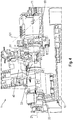
- Fig. 2 shows a schematic perspective view of a further lathe according to the prior art.
- the lathe shown comprises a machine frame designated as a whole by 10, which rises above a base surface 12 and has a machine bed 14 on which a first workpiece spindle 20 is held, which has a first workpiece holder 26.
- the first workpiece spindle 20 is assigned a rod feeding device 30 with which a material rod 32 can be fed to the workpiece spindle 20 of the first workpiece holder 26 through a hollow shaft of a spindle motor 24.
- the first workpiece spindle 20 is assigned a first tool carrier 40 which comprises a rotatable turret head 44 in which a multiplicity of first tools 46 are arranged.
- the relative movement between the first tool 46A and the workpiece WR can be achieved, for example, in that the first tool carrier 40 is seated on a slide system which, opposite the machine bed 14, is parallel to the first spindle axis 28 in a Z direction and perpendicular to the first spindle axis in an X direction.
- Direction is movable.
- a second workpiece spindle 50 which likewise has a second workpiece holder 56, is also arranged on the machine bed 14.
- the second workpiece holder 56 serves to receive the workpiece W, which has been machined on its front side V in the first workpiece spindle 20, and to machine it on its rear side R.
- the second workpiece spindle 50 can be aligned coaxially to first workpiece spindle 20 and can be moved in the direction of first workpiece spindle 20.
- the second workpiece spindle 50 is held in a second spindle carrier, designated as a whole by 60, which can be displaced parallel to the Z-direction via longitudinal guides 68, 70.
- the second workpiece spindle 50 can also be pivoted in the second spindle carrier 60 about a pivot axis 72 which runs perpendicular to a plane of movement E which is spanned by the two directions X and Z.
- the second workpiece spindle 50 is from a position coaxial with the first workpiece spindle 20 into an in Fig. 2
- the position shown in phantom, in which the second workpiece holder 56 faces the base surface 12, can be pivoted.
- the position of the second workpiece spindle 50 shown in phantom corresponds to an unloading position, in which there is the possibility of transferring the workpiece W processed on the rear side R to a workpiece removal device 74.
- a second tool carrier 90 For machining the workpiece W on the rear side R in the second workpiece spindle 50, a second tool carrier 90 is provided which has a turret 94 on which second tools 96 are arranged.
- the second tool carrier 90 is also arranged on a second slide system 98 which can be moved in the Z direction and in the X direction.
- Fig. 3 shows a schematic perspective view of a lathe 1 according to a first embodiment of the present invention.
- the lathe 1 shown has a machine frame 10, a first one on the machine frame 10 in the direction of view Fig. 3 workpiece spindle 20 arranged on the left and one in the direction of view of Fig. 3 arranged on the right second workpiece spindle 30.
- Both workpiece spindles 20, 30 are each provided with workpiece holders 22, 32, which can be rotated about spindle axes 21, 31 of the workpiece spindles 20, 30.
- the workpiece holders 22, 32 are preferably designed as chucks.
- the lathe 1 shown has a first tool carrier 40, which is designed as a turret in order to accommodate a multiplicity of tools and to provide them for machining the workpiece W accommodated in the first workpiece spindle.
- Fig. 3 can also be removed, the top of the machine frame 10 is beveled at the front, the bevel preferably having an angle of 45 degrees.
- the first workpiece spindle 20, which is designed as a stationary workpiece spindle 20 with a horizontally aligned spindle axis 21, to be attached to the machine frame 10 at an angle of 45 degrees, so that the chips occurring during the turning process can be easily removed because they are attached the bevel of the machine frame 10 slide down and can be collected, for example, in a collecting container, not shown.
- the first workpiece spindle 20 has a direct drive, which is designed as a hollow shaft drive. In this way it is possible to load the first workpiece holder 22 by means of a bar loader 200 from the side in which Fig. 3 from the right, to be supplied with raw bar material through the hollow shaft of the direct drive.
- the first tool carrier 40 sits on a third slide system 110, which is also arranged at an angle of 45 degrees upwards, that is to say parallel to the bevel of the machine frame 10.
- the third slide system 110 consists of two guide slides, the first guide slide enabling a movement parallel to the first spindle axis 21 in a so-called X direction and the second guide slide allowing a movement perpendicular to the first spindle axis in a so-called Z 1 direction.
- the Z 1 direction forms a 45 degree angle with a base G on which the machine frame 10 is set up.
- the two guide rails 71 of the first guide carriage are mounted on the top of the machine frame.
- the lathe 1 shown also has a second tool carrier 50, which is also designed as a turret and accommodates a large number of tools which are kept ready for machining a workpiece W held in the second workpiece spindle 30. Again Fig. 3 can be removed, the second tool carrier 50 is arranged on the right of the machine frame 10 and below the spindle carrier 60.
- the second workpiece spindle 30 is arranged on a spindle carrier 60, which can be displaced in the X direction relative to the machine frame 10 parallel to the first spindle axis 21 via a first slide system 70. Furthermore, the first slide system 70 enables a movement of the second workpiece spindle 30 perpendicular to the first spindle axis 21 in a so-called Z 2 direction, which in the position shown runs in the vertical direction, ie perpendicular to the base G.
- the first slide system 70 in turn consists of two guide slides, the first guide slide using the same guide rails 71 as the first guide slide of the third slide system 110.
- the first guide slide carries a bracket 61 of the spindle carrier 60 on which a second bracket 62 can be pivoted by means of a pivot device 80, in particular a rotating assembly (not shown), about a pivot axis 81 which runs perpendicular to a plane of movement E, which is spanned by the X direction and the Z 2 direction.
- a second slide is arranged on the second bracket 62, on which the second workpiece spindle 30 is seated and can thus be moved in two directions and pivoted about an axis, namely the pivot axis 81.
- the second workpiece spindle 30 can, for example, be perpendicular to the first spindle axis 21 (as in FIG Fig. 3 shown) or parallel to the first spindle axis 21 (as in Fig. 4 shown) can be aligned and moved.
- the second tool carrier 50 has a guide slide 55 which, opposite the machine frame 10, is parallel to the pivot axis 81, which runs in a so-called Y direction, ie in the depth direction of the Fig. 3 , is movable.
- a transport device in particular a workpiece removal device, which enables the workpieces W machined by the lathe 1 to be transported away automatically.
- the bevel of the machine frame 10 at the front has a further advantage, namely that it allows the second bracket 62 to be brought closer to the second tool carrier 50, thereby increasing the rigidity of the spindle carrier 60 and thus the machining accuracy of the second Workpiece spindle 30 is improved.
- the guide carriage 55 of the second tool carrier is also in the Machine frame arranged, in particular below the spindle support 60 or the guide rails 71, which also makes it possible to make the lathe 1 more compact.
- Fig. 4 shows a schematic perspective view of a lathe 1 according to a second or alternative embodiment of the present invention.
- the second embodiment has substantially the same structure as that above with respect to FIG Fig. 1 described first embodiment of the present invention.
- the main difference is only that the second workpiece spindle 30 is not designed to be pivotable.
- the second workpiece spindle is oriented vertically so that the required installation space of the lathe 1 can be kept as small as possible.
- the lathe according to the second embodiment has a second tool carrier that sits on a second slide system 90 which is at least opposite the machine frame 10 is movable in the X direction, ie parallel to the first spindle axis 21. Furthermore, the second tool carrier 50 can be pivoted on the second slide system 90 by means of a pivot device 100 about a pivot axis 101 which runs perpendicular to a movement plane E which is defined by the X direction and the Z 2 direction.
- the second tool carrier 50 can also be moved in the Z 2 direction by means of the second slide system 90, which makes it possible to move the second tool carrier 50 in the direction of the second workpiece spindle 30 in order to machine a clamped workpiece.
- the second tool carrier 50 has a third workpiece holder 51 which, in the present embodiment, is implemented as a chuck integrated in a turret disk of a turret of the second tool carrier 50.
- Fig. 5 shows the lathe 1 according to the first embodiment in the state in which the first workpiece spindle 20 is loaded with a raw workpiece using a bar loader 200.
- Fig. 6 also shows the lathe 1 according to the first embodiment, but in the state in which the workpiece W machined by the first workpiece spindle 20 is transferred to the second workpiece spindle 30.
- the workpiece W clamped in the first workpiece spindle 20 can only be machined on the exposed side V.
- FIG. 13 shows the lathe 1 according to the first embodiment in the state in which the second workpiece spindle 30 is pivoted back into the vertical orientation and the workpiece W is swiveled by a tool of FIG second tool holder 50 is processed.
- the second workpiece spindle 30, which is seated on the spindle carrier 60 is brought into a lowermost position on the second slide of the first slide system 70, as shown, in order to bring the workpiece W picked up into a machining area of the second tool holder 50.
- the workpiece W becomes as in FIG Fig. 8 is shown, based on the second workpiece spindle 30, which is located in a vertically aligned position, transferred to a downstream transport device 210.
- the second workpiece spindle 30 is brought into an upper position by means of the spindle carrier 60, in particular the second carriage of the first carriage system 70, in which the workpiece W can be brought over the transport device 210 and, if necessary, on a workpiece carrier, not shown, which is on the transport device 210 is provided for transporting the workpiece W, are deposited.
- the transport device 210 which according to the first embodiment of the present invention is designed as a dragging frame belt, has a lifting table 220 which, in the storage direction of the second workpiece spindle 30, which in Fig. 9 is vertical, is movably mounted. This makes it possible to compensate for tolerances between the workpiece carrier and the delivery position of the second workpiece spindle 30 in the vertical direction.
- Fig. 10 shows a perspective detailed view of the lifting table 220 of the dragging frame belt 210.
- the dragging frame belt 210 has a chain drive (not shown) with a circulating chain, on the basis of which a plurality of dragging frames (not shown) are mounted on one Upper side 211 of the dragging frame belt 210 can be transported endlessly, ie in closed circulation.
- the lifting table 220 has a movable body 221 and a base plate 222 fixedly connected to the towing frame belt 210, the movable body 221 against adjustable stop screws 224, which are designed as four countersunk screws, via four pressure springs 223 which are attached to the base plate 222, is pressed, whereby the movable body 221 is positioned and fixed in an upper position.
- a workpiece support surface 227 of the lifting table 220 which is an upper side of the movable body 221, is aligned approximately level with the upper side 211 of the dragging frame belt 210 in the upper position of the lifting table 220, the alignment being carried out using the adjustable stop screws 224.
- the workpiece support surface 227 can move downwards due to the resilient mounting of the movable body 221.
- the second workpiece spindle 30 presses the movable body 221 downwards, whereby the four countersunk heads of the countersunk screws 224 from four countersunk bores 226, which are provided on the top of a base plate 225 of the movable body 221, loosen and the base plate 225 along the four countersunk screws 224 out, especially in the transverse direction, slides down.
- the movable body 221 of the lifting table 220 is pressed back into the upper position by the four pressure springs 223, whereby the base plate 225 moves upwards again along the countersunk screws 224 and the countersunk heads of the countersunk screws 224 find back into the countersinks of the countersunk bores 226, whereby the bottom plate 225 and thus the movable body 221 is centered.
- the illustrated lifting table 220 has a pressure monitoring, by means of which a pressure path running in the direction of movement B of the movable body 221 can be monitored, the monitoring being carried out by means of two Hall sensors.
Abstract
Die Erfindung stellt eine Werkzeugmaschine 1 zur Bearbeitung von Werkstücken bereit, die ein Maschinengestell 10, eine erste am Maschinengestell 10 angeordnete Werkstückspindel 20 mit einer um eine erste Spindelachse 21 drehbaren ersten Werkstückaufnahme 22, eine zweite am Maschinengestell 10 angeordnete Werkstückspindel 30 mit einer um eine zweite Spindelachse 31 drehbaren zweiten Werkstückaufnahme 32, einen ersten Werkzeugträger 40 zur Bearbeitung eines in der ersten Werkstückspindel 20 gehaltenen Werkstücks W auf einer Seite V, und einen zweiten Werkzeugträger 50 zur Bearbeitung eines in der zweiten Werkstückspindel 30 gehaltenen Werkstücks W auf einer anderen Seite R aufweist. Die zweite Werkstückspindel ist auf einem Spindelträger 60 angeordnet, welcher über ein erstes Schlittensystem 70 gegenüber dem Maschinengestell 10 parallel und quer zur ersten Spindelachse 31 bewegbar ist, die zweite Werkstückspindel 30 ist auf dem Spindelträger 60 mittels einer Schwenkeinrichtung 80 um eine Schwenkachse 81, welche senkrecht zu einer Bewegungsebene E verläuft, schwenkbar, und der zweite Werkzeugträger 50 sitzt auf einem Führungsschlitten 55, der gegenüber dem Maschinengestell 10 parallel zu der Schwenkachse 81 bewegbar ist. Überdies stellt die Erfindung ein Schlepprahmenband mit einem Hubtisch bereit, mit dem Werkstücke zu einer Werkzeugmaschine zugeführt oder von dieser abtransportiert werden können.The invention provides a machine tool 1 for machining workpieces, which has a machine frame 10, a first workpiece spindle 20 arranged on the machine frame 10 with a first workpiece holder 22 rotatable about a first spindle axis 21, a second workpiece spindle 30 arranged on the machine frame 10 with a second workpiece spindle 30 Spindle axis 31 rotatable second workpiece holder 32, a first tool carrier 40 for machining a workpiece W held in the first workpiece spindle 20 on one side V, and a second tool carrier 50 for machining a workpiece W held in the second workpiece spindle 30 on another side R. The second workpiece spindle is arranged on a spindle carrier 60, which can be moved via a first slide system 70 relative to the machine frame 10 parallel and transversely to the first spindle axis 31; the second workpiece spindle 30 is on the spindle carrier 60 by means of a swivel device 80 about a swivel axis 81, which is perpendicular runs to a movement plane E, pivotable, and the second tool carrier 50 sits on a guide slide 55 which can be moved relative to the machine frame 10 parallel to the pivot axis 81. In addition, the invention provides a dragging frame belt with a lifting table with which workpieces can be fed to a machine tool or transported away from it.
Description
Die vorliegende Erfindung betrifft eine Werkzeugmaschine, insbesondere eine Drehmaschine, zur Bearbeitung von Werkstücken, insbesondere zur Bearbeitung von Stangenmaterial. Ferner betrifft die vorliegende Erfindung ein Schlepprahmenband für die Zufuhr von zu bearbeitenden Werkstücken zu einer Werkzeugmaschine oder für die Abfuhr von durch die Werkzeugmaschine bearbeitete Werkstücke.The present invention relates to a machine tool, in particular a lathe, for processing workpieces, in particular for processing bar material. The present invention also relates to a dragging frame belt for supplying workpieces to be processed to a machine tool or for removing workpieces processed by the machine tool.
Bekannt sind Drehmaschinen zur Bearbeitung von Werkstücken, bei denen in einer Werkzeugmaschine beide Enden des Werkstücks bearbeitet werden können, d.h. eine Zweiseitenbearbeitung des Werkstücks durchgeführt werden kann.Lathes for machining workpieces are known in which both ends of the workpiece can be machined in one machine tool, i. a two-sided machining of the workpiece can be carried out.
Bei der in
Da jeder Spindelstock sowohl eine Werkstückspindel als auch Werkzeuge trägt, und während der Bearbeitung jeweils beide Spindelstöcke am Bearbeitungsvorgang beteiligt sind, kann während der Bearbeitungszeit immer nur ein Werkstück bearbeitet werden, und während dieser Zeit kann auch kein anderes Werkstück gehandhabt werden. Die Zeit von der Aufnahme eines Ausgangswerkstücks bis zur Ablage eines vollständig bearbeiteten Werkstücks ist deshalb vergleichsweise lang und der Durchsatz derartiger Drehmaschinen eher niedrig.Since each headstock carries both a workpiece spindle and tools, and both headstocks are involved in the machining process during machining, only one workpiece can be machined during the machining time and no other workpiece can be handled during this time. The time from picking up an initial workpiece to depositing a completely machined workpiece is therefore comparatively long and the throughput of such lathes is rather low.
Aus den genannten Gründen besteht daher schon länger das Bestreben Drehmaschinen bereitzustellen, bei denen Bearbeitungsvorgänge und Handhabungsvorgänge einander zeitlich überlappen können.For the reasons mentioned, there has been an endeavor for a long time to provide lathes in which machining processes and handling processes can overlap in time.
Hierzu lehrt beispielsweise die
Ferner beschreibt die
Ferner beschrieben ist ein erster mit mindestens einem Werkzeug bestückter Werkzeugträger zur Bearbeitung eines in der ersten Werkstückspindel gehaltenen Werkstücks auf einer Seite, ein zweiter mit mindestens einem Werkzeug bestückter Werkzeugträger zur Bearbeitung eines in der zweiten Werkstückspindel gehaltenen Werkstücks auf einer anderen Seite. Die erste und die zweite Werkstückspindel mit einander zugewandten Werkstückaufnahmen sind zur direkten Übergabe des auf der einen Seite bearbeiteten Werkstücks von einer der Werkstückaufnahmen in die jeweils andere Werkstückaufnahme in eine Übergabestellung der Werkstückspindeln bewegbar. Hierbei sind die Spindelachsen koaxial zueinander ausgerichtet und in Richtung der Achsen bewegbar, wobei der ersten Werkstückspindel zum Laden des rohen Werkstücks eine Stangenzuführeinrichtung zugeordnet ist. Das fertig bearbeitete Werkstück kann von der zweiten Werkstückspindel mit quer zur ersten Spindelachse verlaufender zweiter Spindelachse einer Werkstückabfuhreinrichtung übergeben werden.Also described is a first tool holder equipped with at least one tool for machining a workpiece held in the first workpiece spindle on one side, and a second tool holder equipped with at least one tool for machining a workpiece held in the second workpiece spindle on the other side. The first and second workpiece spindles with facing workpiece holders can be moved into a transfer position of the workpiece spindles for the direct transfer of the workpiece processed on one side from one of the workpiece holders to the other workpiece holder. Here, the spindle axes are aligned coaxially to one another and can be moved in the direction of the axes, a bar feed device being assigned to the first workpiece spindle for loading the raw workpiece. The finished workpiece can be taken from the second workpiece spindle with the second spindle running transversely to the first spindle axis Spindle axis are transferred to a workpiece removal device.
Die geschilderte Drehmaschine ist jedoch mit dem Problem behaftet, dass bei der Abgabe des Werkstücks durch die zweite Werkstückspindel an die nachgeschaltete Werkstückabfuhreinrichtung das Werkstück lediglich ungenau auf der Werkstückabfuhreinrichtung, insbesondere einem Trägerelement der Werkstückabfuhreinrichtung, positioniert werden kann, wodurch die in der Drehmaschine vorhandenen Lage- und Ausrichtungsinformationen über das Werkstück bei der Übergabe an die Werkstückabfuhreinrichtung verloren gehen.The lathe described has the problem, however, that when the workpiece is delivered by the second workpiece spindle to the downstream workpiece removal device, the workpiece can only be positioned imprecisely on the workpiece removal device, in particular a carrier element of the workpiece removal device, whereby the position in the lathe and alignment information about the workpiece is lost when it is transferred to the workpiece removal device.
Der Erfindung liegt die Aufgabe zu Grunde, eine Werkzeugmaschine bereitzustellen, die in der Lage ist, einerseits Bearbeitungsvorgänge und Handhabungsvorgänge einander zeitlich zu überlappen, um die Zeit von der Aufnahme eines Ausgangswerkstücks bis zur Ablage eines vollständig bearbeiteten Werkstücks zu minimieren, andererseits die in der Werkzeugmaschine gewonnenen Lage- und Ausrichtungsinformationen über das bearbeitete Werkstück für nachgeschaltete Bearbeitungsschritte verfügbar zu machen und gleichzeitig eine kompakte und in sich steife Bauweise zu realisieren, um unnötige Schwingungen die das Bearbeitungsergebnis beeinträchtigen könnten zu vermeiden.The invention is based on the object of providing a machine tool which is capable of overlapping machining processes and handling processes on the one hand in order to minimize the time from picking up an initial workpiece to storing a completely machined workpiece, and on the other hand that in the machine tool To make the position and alignment information obtained about the machined workpiece available for subsequent machining steps and at the same time to implement a compact and inherently rigid construction in order to avoid unnecessary vibrations that could impair the machining result.
Diese Aufgabe wird gelöst durch eine Werkzeugmaschine, insbesondre Drehmaschine, nach Anspruch 1 oder 2. Überdies stellt die Erfindung ein Schlepprahmenband mit einem Hubtisch für die Zufuhr/Abfuhr von Werkstücken an/von einer Werkzeugmaschine bereit, das dazu eingerichtet ist, die von der Werkzeugmaschine gewonnen Lage- und Ausrichtungsinformationen an nachgeschaltete Bearbeitungsschritte zu übertragen.This object is achieved by a machine tool, in particular a lathe, according to
Hierbei ist einer der Kerngedanken der vorliegenden Erfindung, eine Werkzeugmaschine bereitzustellen, welche zwei Werkstückspindeln aufweist, von denen die im Bearbeitungsfluss der Werkzeugmaschine später angeordnete Werkstückspindel zumindest in eine vertikale Ausrichtung bringbar ist, d.h. die Werkstückspindel zumindest eine Stellung aufweist, in der eine Spindelachse selbiger senkrecht zu einer Grundfläche, auf der ein Maschinengestell der Werkzeugmaschine steht, senkrecht ist, und diese Werkstückspindel anhand eines Schlittensystems in dieser vertikalen Richtung bewegbar ist.One of the core ideas of the present invention is to provide a machine tool which has two workpiece spindles, of which the workpiece spindle later arranged in the machining flow of the machine tool can be brought into at least a vertical orientation, i.e. the workpiece spindle has at least one position in which a spindle axis of the same is perpendicular to a base surface on which a machine frame of the machine tool stands, and this workpiece spindle can be moved in this vertical direction using a slide system.
Dadurch, dass die Werkstückspindel, welche die Endbearbeitung des Werkstücks innerhalb der Werkzeugmaschine durchführt eine Stellung annehmen kann, in welcher die Werkstückspindel vertikal ausgerichtet ist, und zudem in der vertikalen Richtung verlagerbar ist, ist es möglich, das fertigbearbeitete Werkstück beispielsweise an eine nachgeschaltete Transporteinrichtung zu übergeben, ohne die in der Werkzeugmaschine gewonnenen Lage und Ausrichtungsinformationen über das Werkzeug zu verlieren.Because the workpiece spindle, which carries out the final machining of the workpiece within the machine tool, can assume a position in which the workpiece spindle is vertically aligned and can also be displaced in the vertical direction, it is possible, for example, to deliver the finished workpiece to a downstream transport device without losing the position and alignment information about the tool obtained in the machine tool.
Ferner ist es auch denkbar, anhand dieser Werkstückspindel ein bereits bearbeitetes Werkstück, welches mit Lage- und Ausrichtungsinformationen der Werkzeugmaschine zugeführt wird, aufzunehmen, ohne diese Lage- und Ausrichtungsinformationen zu verlieren.Furthermore, it is also conceivable to use this workpiece spindle to pick up an already machined workpiece, which is fed to the machine tool with position and orientation information, without losing this position and orientation information.
Gemäß einer Ausführungsform der vorliegenden Erfindung weist eine Werkzeugmaschine, insbesondere Drehmaschine, zur Bearbeitung von Werkstücken, insbesondere zur Bearbeitung von Stangenmaterial, auf: ein Maschinengestell, eine erste am Maschinengestell angeordnete Werkstückspindel mit einer um eine erste Spindelachse drehbaren ersten Werkstückaufnahme, eine zweite am Maschinengestell angeordnete Werkstückspindel mit einer um eine zweite Spindelachse drehbaren zweiten Werkstückaufnahme, einen ersten mit mindestens einem Werkzeug bestückten Werkzeugträger zur Bearbeitung eines in der ersten Werkstückspindel gehaltenen Werkstücks auf einer Seite, und einen zweiten mit mindestens einem Werkzeug bestückten Werkzeugträger zur Bearbeitung eines in der zweiten Werkstückspindel gehaltenen Werkstücks auf einer anderen Seite, wobei die zweite Werkstückspindel auf einem Spindelträger angeordnet ist, welcher über ein erstes Schlittensystem gegenüber dem Maschinengestell parallel zur ersten Spindelachse in einer sogenannten X-Richtung und quer, insbesondere senkrecht, zur ersten Spindelachse in einer sogenannten Z2-Richtung bewegbar ist, die zweite Werkstückspindel auf dem Spindelträger mittels einer Schwenkeinrichtung um eine Schwenkachse, welche senkrecht zu einer Bewegungsebene verläuft, die durch die X-Richtung und die Z2-Richtung definiert ist, schwenkbar ist, und der zweite Werkzeugträger auf einem Führungsschlitten sitzt, der gegenüber dem Maschinengestell parallel zu der Schwenkachse, die in einer sogenannten Y-Richtung verläuft, bewegbar ist.According to one embodiment of the present invention, a machine tool, in particular a lathe, for processing workpieces, in particular for processing bar material, has: a machine frame, a first workpiece spindle arranged on the machine frame with a first workpiece holder rotatable about a first spindle axis, a second arranged on the machine frame Workpiece spindle with a second workpiece holder rotatable about a second spindle axis, a first with at least one tool equipped tool carrier for machining a workpiece held in the first workpiece spindle on one side, and a second tool carrier equipped with at least one tool for machining a workpiece held in the second workpiece spindle on the other side, the second workpiece spindle being arranged on a spindle carrier which is over a first slide system is movable opposite the machine frame parallel to the first spindle axis in a so-called X direction and transversely, in particular perpendicular, to the first spindle axis in a so-called Z 2 direction, the second workpiece spindle on the spindle carrier by means of a swivel device about a swivel axis which is perpendicular runs to a movement plane which is defined by the X-direction and the Z 2 -direction, is pivotable, and the second tool carrier sits on a guide carriage which is opposite the machine frame parallel to the pivot axis, which is in a so-called Y -Direction runs, is movable.
Gemäß einer alternativen Ausführungsform der vorliegenden Erfindung weist eine Werkzeugmaschine, insbesondere eine Drehmaschine, zur Bearbeitung von Werkstücken, insbesondere zur Bearbeitung von Stangenmaterial, auf: ein Maschinengestell, eine erste am Maschinengestell angeordnete Werkstückspindel mit einer um eine erste Spindelachse drehbaren ersten Werkstückaufnahme, eine zweite am Maschinengestell angeordnete Werkstückspindel mit einer um eine zweite Spindelachse drehbaren zweiten Werkstückaufnahme, einen ersten mit mindestens einem Werkzeug bestückten Werkzeugträger zur Bearbeitung eines in der ersten Werkstückspindel gehaltenen Werkstücks auf einer Seite, und einen zweiten mit mindestens einem Werkzeug bestückten Werkzeugträger zur Bearbeitung eines in der zweiten Werkstückspindel gehaltenen Werkstücks auf einer anderen Seite, wobei die zweite Werkstückspindel auf einem Spindelträger angeordnet ist, welcher über ein erstes Schlittensystem gegenüber dem Maschinengestell parallel zur ersten Spindelachse in einer sogenannten X-Richtung und quer, insbesondere senkrecht, zur ersten Spindelachse in einer sogenannten Z2-Richtung bewegbar ist, der zweite Werkzeugträger auf einem zweiten Schlittensystem sitzt, welches gegenüber dem Maschinengestell zumindest in der X-Richtung bewegbar ist, und der zweite Werkzeugträger auf dem zweiten Schlittensystem mittels einer Schwenkeinrichtung um eine Schwenkachse, welche senkrecht zu einer Bewegungsebene verläuft, die durch die X-Richtung und die Z2-Richtung definiert ist, schwenkbar ist.According to an alternative embodiment of the present invention, a machine tool, in particular a lathe, for processing workpieces, in particular for processing bar material, has: a machine frame, a first workpiece spindle arranged on the machine frame with a first workpiece holder rotatable about a first spindle axis, a second on the Machine frame arranged workpiece spindle with a second workpiece holder rotatable about a second spindle axis, a first tool carrier equipped with at least one tool for machining a workpiece held in the first workpiece spindle on one side, and a second tool carrier equipped with at least one tool for machining one in the second workpiece spindle held workpiece on another side, wherein the second workpiece spindle is arranged on a spindle carrier, which is parallel to the machine frame via a first slide system r first spindle axis is movable in a so-called X-direction and transversely, in particular perpendicularly, to the first spindle axis in a so-called Z 2 -direction, the second tool carrier sits on a second slide system, which is movable with respect to the machine frame at least in the X-direction, and the second tool carrier can be pivoted on the second slide system by means of a pivot device about a pivot axis which runs perpendicular to a plane of movement which is defined by the X direction and the Z 2 direction.
Ferner ist es vorteilhaft, wenn der zweite Werkzeugträger anhand des zweiten Schlittensystems gegenüber dem Maschinengestell zusätzlich in der Z2-Richtung und/oder parallel zur Schwenkachse, die in einer sogenannten Y-Richtung verläuft, bewegbar ist.Furthermore, it is advantageous if the second tool carrier can also be moved in the Z 2 direction and / or parallel to the pivot axis, which runs in a so-called Y direction, with respect to the machine frame with the aid of the second slide system.
Des Weiteren ist es bevorzugt, dass der zweite Werkzeugträger eine dritte Werkstückaufnahme aufweist, anhand der das in der ersten Werkstückspindel bearbeitete Werkstück aufgenommen und an die zweite Werkstückspindel zur Weiterberarbeitung übergeben werden kann.Furthermore, it is preferred that the second tool carrier has a third workpiece holder by means of which the workpiece machined in the first workpiece spindle can be picked up and transferred to the second workpiece spindle for further processing.
Weiterhin ist es vorteilhaft, wenn die dritte Werkstückaufnahme durch ein Spannfutter, das in einer Revolverscheibe eines Revolvers des zweiten Werkzeugträgers integriert ist, realisiert ist.Furthermore, it is advantageous if the third workpiece holder is realized by a chuck which is integrated in a turret disk of a turret of the second tool carrier.
Ferner ist es bevorzugt, dass der erste Werkzeugträger auf einem dritten Schlittensystem sitzt, welches gegenüber dem Maschinengestell parallel zur ersten Spindelachse in der X-Richtung und quer, insbesondere senkrecht, zur ersten Spindelachse in einer sogenannten Z1-Richtung bewegbar ist.Furthermore, it is preferred that the first tool carrier sits on a third slide system which can be moved in relation to the machine frame parallel to the first spindle axis in the X direction and transversely, in particular perpendicular, to the first spindle axis in a so-called Z 1 direction.
Des Weiteren ist es vorteilhaft, dass die Bewegungsrichtung Z1-Richtung des dritten Schlittensystems des ersten Werkzeugträgers einen Winkel von etwa 30° bis 60°, bevorzugt 45°, mit einer Grundfläche, auf der das Maschinengestell steht, bildet.Furthermore, it is advantageous that the direction of movement Z 1 direction of the third slide system of the first tool carrier is at an angle of approximately 30 ° to 60 °, preferably 45 °, with a base on which the machine frame stands.
Gemäß einer weiteren Ausführungsform der vorliegenden Erfindung verwenden das dritte Schlittensystem und das erste Schlittensystem in der X-Richtung gemeinsame Führungsschienen.According to a further embodiment of the present invention, the third slide system and the first slide system use common guide rails in the X direction.
Ferner ist es bevorzugt, dass an der ersten Werkstückspindel zum Laden des unbearbeiteten Werkstücks eine Stangenzuführeinrichtung, insbesondere ein Stangenlader, angeordnet ist.Furthermore, it is preferred that a bar feed device, in particular a bar loader, is arranged on the first workpiece spindle for loading the unprocessed workpiece.
Weiterhin ist es vorteilhaft, wenn die erste Werkstückspindel als ein Direktantrieb mit einer Hohlwelle ausgebildet ist, bei dem das unbearbeitete Werkstück durch die Hohlwelle des Direktantriebs zu der ersten Werkstückaufnahme zuführbar ist.It is also advantageous if the first workpiece spindle is designed as a direct drive with a hollow shaft, in which the unmachined workpiece can be fed to the first workpiece holder through the hollow shaft of the direct drive.
Ferner ist es bevorzugt, dass die erste Werkstückspindel und/oder die zweite Werkstückspindel als ein Direktantrieb, bevorzugt ein Synchronmotor, mit einem maximalen Drehmoment im Bereich von 200 bis 400 Nm und einer Drehzahl im Bereich von 0 bis 5000 U/min ausgebildet ist bzw. sind.Furthermore, it is preferred that the first workpiece spindle and / or the second workpiece spindle is or is designed as a direct drive, preferably a synchronous motor, with a maximum torque in the range from 200 to 400 Nm and a speed in the range from 0 to 5000 rpm. are.
Gemäß einer weiteren Ausführungsform der vorliegenden Erfindung ist die erste Werkstückspindel als eine stationäre Werkstückspindel ausgebildet.According to a further embodiment of the present invention, the first workpiece spindle is designed as a stationary workpiece spindle.
Des Weiteren ist es bevorzugt, dass der Führungsschlitten innerhalb des Maschinengestells, insbesondere unterhalb der Führungsschienen, vorgesehen ist.Furthermore, it is preferred that the guide carriage is provided within the machine frame, in particular below the guide rails.
Ferner ist es vorteilhaft, wenn die zweite Werkstückspindel oder der zweite Werkzeugträger in eine Koaxialstellung, in der die erste Werkstückaufnahme mit der zweiten Werkstückaufnahme oder die erste Werkstückaufnahme mit der dritten Werkstückaufnahme koaxial ist, schwenkbar ist.It is also advantageous if the second workpiece spindle or the second tool carrier can be pivoted into a coaxial position in which the first workpiece holder is coaxial with the second workpiece holder or the first workpiece holder is coaxial with the third workpiece holder.
Es ist ebenfalls bevorzugt, die Schwenkeinrichtung als einen Drehkranz auszubilden.It is also preferred to design the pivoting device as a turntable.
Weiterhin ist es vorteilhaft, wenn die Werkzeugmaschine eine Transporteinrichtung, insbesondere eine Werkstückabfuhreinrichtung, aufweist, anhand der durch die Werkzeugmaschine bearbeite Werkstücke abtransportiert und/oder einer weiteren Bearbeitungsvorrichtung zugeführt werden können. Es ist jedoch auch möglich, anhand der Transporteinrichtung der Werkezugmaschine Werkstücke, insbesondere bereits bearbeitete Werkstücke, zuzuführen.Furthermore, it is advantageous if the machine tool has a transport device, in particular a workpiece removal device, with the aid of which workpieces processed by the machine tool can be transported away and / or fed to a further processing device. However, it is also possible to use the transport device to feed workpieces, in particular workpieces that have already been processed, to the machine tool.
Gemäß einer weiteren Ausführungsform nimmt die zweite Werkstückspindel in einer vertikalen Ausrichtung, in der sie senkrecht zur ersten Spindelachse und senkrecht zur Grundfläche ist, eine Entladestellung ein, in welcher die Möglichkeit besteht, das auf der Rückseite bearbeitete Werkstück bzw. das fertig bearbeitete Werkstück der Transporteinrichtung zu übergeben.According to a further embodiment, the second workpiece spindle in a vertical orientation, in which it is perpendicular to the first spindle axis and perpendicular to the base, assumes an unloading position in which there is the possibility of removing the workpiece processed on the rear side or the finished workpiece of the transport device to hand over.
Des Weiteren ist es bevorzugt, wenn die Transporteinrichtung als ein Schlepprahmenband, ein Pallettenförderer mit Indexierung oder ein Shuttle ausgebildet ist.Furthermore, it is preferred if the transport device is designed as a dragging frame belt, a pallet conveyor with indexing or a shuttle.
Ferner ist es vorteilhaft, dass die Transporteinrichtung als ein Schlepprahmenband mit Hubtisch ausgebildet ist, wobei der Hubtisch dazu eingerichtet ist, in einer Ablage-/Aufnahmerichtung der zweiten Werkstückspindel, die senkrecht zur Grundfläche ist, beweglich gelagert zu sein.Furthermore, it is advantageous that the transport device is designed as a dragging frame belt with a lifting table, the lifting table being set up to be movably supported in a storage / receiving direction of the second workpiece spindle that is perpendicular to the base area.
Ferner betrifft die vorliegende Erfindung ein Schlepprahmenband, für die Zufuhr/Abfuhr von Werkstücken an/von einer Werkzeugmaschine, insbesondere einer Werkzeugmaschine nach einem der vorhergehenden Ansprüche, aufweisen: einen Kettentrieb mit umlaufender Kette für den Transport einer Vielzahl von Schlepprahmen, die auf einer Oberseite des Schlepprahmenbands endlos umlaufen, und einen Hubtisch, der dazu eingerichtet ist, in einer Ablage/Aufnahmerichtung der zu transportierenden Werkstücke, die senkrecht zu einer Grundfläche ist, auf der das Schlepprahmenband steht, beweglich gelagert zu sein.Furthermore, the present invention relates to a dragging frame belt for the supply / removal of workpieces to / from a machine tool, in particular a machine tool according to one of the preceding claims, having: a chain drive with a circulating chain for the transport of a plurality of dragging frames, which on a Revolve the top of the dragging frame belt endlessly, and a lifting table which is set up to be movably supported in a storage / receiving direction of the workpieces to be transported that is perpendicular to a base area on which the dragging frame belt stands.
Des Weiteren ist es vorteilhaft, wenn der Hubtisch einen beweglichen Körper und eine fest mit dem Schlepprahmenband verbundene Grundplatte aufweist, wobei der bewegliche Körper über zumindest zwei Andruckfedern, bevorzugt vier Andruckfedern, die an der Grundplatte befestigt sind, gegen einstellbare Anschlagschrauben, bevorzugt vier Senkschrauben, die als Anschlag für den beweglichen Körper dienen, gedrückt wird, wodurch der bewegliche Körper in einer oberen Position positionierbar und fixierbar ist.Furthermore, it is advantageous if the lifting table has a movable body and a base plate firmly connected to the towing frame belt, the movable body against adjustable stop screws, preferably four countersunk screws, via at least two pressure springs, preferably four pressure springs, which are attached to the base plate, which serve as a stop for the movable body, is pressed, whereby the movable body can be positioned and fixed in an upper position.
Gemäß einer Ausführungsform der vorliegender Erfindung weist eine Bodenplatte des beweglichen Körpers vier Bohrungen, insbesondere Senkbohrungen, auf, durch welche die einstellbaren Anschlagschrauben hindurchstehen, wodurch der bewegliche Körper quer zu seiner Bewegungsrichtung, welche der Ablage/Aufnahmerichtung der Werkstücke entspricht, geführt ist.According to one embodiment of the present invention, a base plate of the movable body has four bores, in particular countersunk bores, through which the adjustable stop screws protrude, whereby the movable body is guided transversely to its direction of movement, which corresponds to the storage / pick-up direction of the workpieces.
Des Weiteren ist es bevorzugt, dass der Hubtisch so eingerichtet ist, dass eine Werkstückauflagefläche des Hubtischs, die eine Oberseite des beweglichen Körpers ist, in etwa eben zu der Oberseite des Schlepprahmenbands ausrichtbar ist, wobei die Ausrichtung anhand der einstellbaren Anschlagschrauben vornehmbar ist.Furthermore, it is preferred that the lifting table is set up in such a way that a workpiece support surface of the lifting table, which is an upper side of the movable body, can be aligned approximately level with the upper side of the dragging frame belt, the alignment being able to be carried out using the adjustable stop screws.
Weiterhin ist es vorteilhaft, wenn der Hubtisch eine Andrücküberwachung aufweist, mittels welcher ein Andrückweg, der in Richtung der Bewegungsrichtung des beweglichen Körpers verläuft, überwacht werden kann, bevorzugt erfolgt die Überwachung mittels zweier Hall-Sensoren.Furthermore, it is advantageous if the lifting table has a pressure monitoring device, by means of which a pressure path that runs in the direction of movement of the movable body can be monitored; monitoring preferably takes place by means of two Hall sensors.
-
Fig. 1 zeigt eine schematische perspektivische Ansicht einer Drehmaschine gemäß dem Stand der Technik,Fig. 1 shows a schematic perspective view of a lathe according to the prior art, -
Fig. 2 zeigt eine schematische perspektivische Ansicht einer weiteren Drehmaschine gemäß dem Stand der Technik,Fig. 2 shows a schematic perspective view of a further lathe according to the prior art, -
Fig. 3 zeigt eine schematische perspektivische Ansicht einer Drehmaschine gemäß einer ersten Ausführungsform der vorliegenden Erfindung,Fig. 3 shows a schematic perspective view of a lathe according to a first embodiment of the present invention, -
Fig. 4 zeigt eine schematische perspektivische Ansicht einer Drehmaschine gemäß einer zweiten Ausführungsform der vorliegenden Erfindung,Fig. 4 shows a schematic perspective view of a lathe according to a second embodiment of the present invention, -
Fig. 5 zeigt eine schematische perspektivische Ansicht der Drehmaschine gemäß der ersten Ausführungsform in dem Zustand, in dem die erste Werkstückspindel anhand eines Stangenladers mit einem Rohwerkstück beladen wird,Fig. 5 shows a schematic perspective view of the lathe according to the first embodiment in the state in which the first workpiece spindle is loaded with a raw workpiece using a bar loader, -
Fig. 6 zeigt eine schematische perspektivische Ansicht der Drehmaschine gemäß der ersten Ausführungsform in dem Zustand, in dem das durch die erste Werkstückspindel bearbeitete Werkstück an die zweite Werkstückspindel übergeben wird,Fig. 6 shows a schematic perspective view of the lathe according to the first embodiment in the state in which the workpiece machined by the first workpiece spindle is transferred to the second workpiece spindle, -
Fig. 7 zeigt eine schematische perspektivische Ansicht der Drehmaschine gemäß der ersten Ausführungsform in dem Zustand, in dem die zweite Werkstückspindel zurück in die vertikale Ausrichtung geschwenkt ist und das Werkstück durch ein Werkzeug der zweiten Werkzeugaufnahme bearbeitet wird,Fig. 7 shows a schematic perspective view of the lathe according to the first embodiment in the state in which the second workpiece spindle is pivoted back into the vertical orientation and the workpiece is being machined by a tool of the second tool holder, -
Fig. 8 zeigt eine schematische perspektivische Ansicht der Drehmaschine gemäß der ersten Ausführungsform in dem Zustand, in dem das fertigbearbeitete Werkstück anhand der zweiten Werkstückspindel an eine nachgeschaltete Transporteinrichtung übergeben wird,Fig. 8 shows a schematic perspective view of the lathe according to the first embodiment in the state in which the finished workpiece is transferred to a downstream transport device using the second workpiece spindle, -
Fig. 9 zeigt einen perspektivische Detailansicht der nachgeschalteten Transporteinrichtung, die als ein Schlepprahmenband mit Hubtisch ausgebildet ist,Fig. 9 shows a perspective detailed view of the downstream transport device, which is designed as a dragging frame belt with lifting table, -
Fig. 10 zeigt eine perspektivische Detailansicht des Hubtischs des Schlepprahmenbands.Fig. 10 shows a perspective detailed view of the lifting table of the dragging frame belt.
Nachfolgend werden anhand der beigefügten Figuren bevorzugte Ausführungsformen der vorliegenden Erfindung im Detail beschrieben. Weitere in diesem Zusammenhang genannte Modifikationen bestimmter Merkmale können jeweils einzeln miteinander kombiniert werden, um weitere Ausführungsformen auszubilden.In the following, preferred embodiments of the present invention are described in detail with reference to the accompanying figures. Further modifications of certain features mentioned in this context can each be individually combined with one another in order to form further embodiments.
Dabei sind in den verschiedenen Figuren gleiche oder entsprechende Elemente jeweils mit den gleichen oder ähnlichen Bezugszeichen bezeichnet.Identical or corresponding elements are each designated by the same or similar reference symbols in the various figures.
Die Planschlitten 3 sind als Konsolen ausgeführt, an deren Unterseite Planführungen 3a vorgesehen sind. Die Planführungen 3a gleiten in Führungsschuhen auf der Oberseite des Bettschlittens 2. An den Frontseiten der Planschlitten 3 sind Längsführungen 3b vorgesehen, in denen der Längsschlitten 4 in vertikaler Richtung verfahrbar ist. Die Vorschubantriebe für die Schlitten 2, 3 und 4 sind nicht dargestellt. Auf diese Weise sind die Werkstückspindeln 5 und 6 jeweils in den drei Raumrichtungen X, Y und Z verfahrbar sowie um eine Schwenkachse, die parallel zur Y-Achse ist, schwenkbar.The cross slide 3 are designed as consoles, on the underside of which plan guides 3a are provided. The
Die Relativbewegung zwischen dem ersten Werkzeug 46A und dem Werkstück WR ist beispielsweise dadurch erreichbar, dass der erste Werkzeugträger 40 auf einem Schlittensystem sitzt, welches gegenüber dem Maschinenbett 14 parallel zur ersten Spindelachse 28 in einer Z-Richtung und senkrecht zur ersten Spindelachse in einer X-Richtung bewegbar ist.The relative movement between the
Auf dem Maschinenbett 14 ist ferner eine zweite Werkstückspindel 50 angeordnet, welche ebenfalls eine zweite Werkstückaufnahme 56 aufweist. Die zweite Werkstückaufnahme 56 dient dabei dazu, das in der ersten Werkstückspindel 20 auf seiner Vorderseite V bearbeitete Werkstück W mit der Vorderseite V aufzunehmen und auf seiner Rückseite R zu bearbeiten.A
Zum Übernehmen des auf der Vorderseite V bearbeiten Werkstücks W von der ersten Werkstückspindel 20 ist die zweite Werkstückspindel 50 koaxial zur ersten Werkstückspindel 20 ausrichtbar und in Richtung der ersten Werkstückspindel 20 bewegbar.To take over the workpiece W processed on the front side V from the
Hierzu ist die zweite Werkstückspindel 50 in einem als Ganzes mit 60 bezeichneten zweiten Spindelträger gehalten, welcher über Längsführungen 68, 70 parallel zur Z-Richtung verschiebbar ist. Die zweite Werkstückspindel 50 ist ferner in dem zweiten Spindelträger 60 um eine Schwenkachse 72 schwenkbar, welche senkrecht zu einer Bewegungsebene E verläuft, die durch die beiden Richtungen X und Z aufgespannt ist. Dadurch ist die zweite Werkstückspindel 50 von einer zur ersten Werkstückspindel 20 koaxialen Stellung in eine in
Die in
Zur Bearbeitung des Werkstücks W auf der Rückseite R in der zweiten Werkstückspindel 50 ist ein zweiter Werkzeugträger 90 vorgesehen, welcher einen Revolverkopf 94 aufweist, an welchem zweite Werkzeuge 96 angeordnet sind. Der zweite Werkzeugträger 90 ist ebenfalls auf einem zweiten Schlittensystem 98 angeordnet, welches in der Z-Richtung und in der X-Richtung bewegbar ist.For machining the workpiece W on the rear side R in the
Wie der
Ferner weist die erste Werkstückspindel 20 einen Direktantrieb auf, welcher als Hohlwellenantrieb ausgebildet ist. Auf diese Weise ist es möglich, die erste Werkstückaufnahme 22 mittels eines Stangenladers 200 von der Seite, in der
Des Weiteren sitzt der erste Werkzeugträger 40 auf einem dritten Schlittensystem 110, welches ebenfalls in einem Winkel von 45 Grad nach oben, also parallel zu der Abschrägung des Maschinengestells 10, angeordnet ist. Hierdurch kann die Breite bzw. Tiefe der Werkzeugmaschine 1 reduziert werden, da das Schlittensystem 110 den freien Raum in vertikaler Richtung ausnützt. Das dritte Schlittensystem 110 besteht aus zwei Führungsschlitten, wobei der erste Führungsschlitten eine Bewegung parallel zur ersten Spindelachse 21 in einer sogenannten X-Richtung ermöglicht und der zweite Führungsschlitten eine Bewegung senkrecht zur ersten Spindelachse in einer sogenannten Z1-Richtung ermöglicht. Die Z1-Richtung bildet in der dargestellten Ausführungsform wie oben bereits geschildert einen 45 Grad Winkel mit einer Grundfläche G auf welcher das Maschinengestell 10 aufgestellt ist. Die zwei Führungsschienen 71 des ersten Führungsschlitten sind an der Oberseite des Maschinengestells montiert.Furthermore, the
Ferner weist die dargestellte Drehmaschine 1 einen zweiten Werkzeugträger 50 auf, welcher ebenfalls als Revolver ausgebildet ist und eine Vielzahl an Werkzeugen aufnimmt, welche zur Bearbeitung eines in der zweiten Werkstückspindel 30 gehaltenen Werkstücks W bereitgehalten werden. Wie der
Die zweite Werkstückspindel 30 ist auf einem Spindelträger 60 angeordnet, welcher über ein erstes Schlittensystem 70 gegenüber dem Maschinengestellt 10 parallel zur ersten Spindelachse 21 in der X-Richtung verschiebbar ist. Ferner ermöglicht das erste Schlittensystem 70 eine Bewegung der zweiten Werkstückspindel 30 senkrecht zur ersten Spindelachse 21 in einer sogenannten Z2-Richtung, welche in der dargestellten Stellung in vertikaler Richtung verläuft, d.h. senkrecht zur Grundfläche G.The
Das erste Schlittensystem 70 besteht wiederum aus zwei Führungsschlitten, wobei der erste Führungsschlitten die gleichen Führungsschienen 71 nutzt, wie der erste Führungsschlitten des dritten Schlittensystems 110. Der erste Führungsschlitten trägt eine Konsole 61 des Spindelträgers 60 an dem eine zweite Konsole 62 mittels einer Schwenkeinrichtung 80, insbesondere einem nicht dargestellten Drehkranz, um eine Schwenkachse 81, welche senkrecht zu einer Bewegungsebene E verläuft, die durch die X-Richtung und die Z2-Richtung aufgespannt ist, schwenkbar ist. Auf der zweiten Konsole 62 ist ein zweiter Schlitten angeordnet, auf dem die zweite Werkstückspindel 30 sitzt und somit in zwei Richtungen bewegbar und um eine Achse, nämlich die Schwenkachse 81, schwenkbar ist. Abhängig von der Schwenkstellung der zweiten Konsole 62 kann beispielsweise die zweite Werkstückspindel 30 senkrecht zur ersten Spindelachse 21 (wie in
Wie der
Der
Der
In der dargestellten Ausführungsform ist ferner der Führungsschlitten 55 des zweiten Werkzeugträgers in dem Maschinengestell angeordnet, insbesondere unterhalb des Spindelträgers 60 bzw. der Führungsschienen 71, wodurch es ebenfalls ermöglicht wird, die Drehmaschine 1 kompakter zu gestallten.In the embodiment shown, the
Um dennoch in der Lage zu sein, eine automatische Werkstückübergabe von der ersten Werkstückspindel 20 zu der zweiten Werkstückspindel 30 zu realisieren, weist die Drehmaschine gemäß der zweiten Ausführungsform einen zweiten Werkzeugträger auf, der auf einem zweiten Schlittensystem 90 sitzt, welches gegenüber dem Maschinengestell 10 zumindest in der X-Richtung, d.h. parallel zu der ersten Spindelachse 21, bewegbar ist. Ferner ist der zweite Werkzeugträger 50 auf dem zweiten Schlittensystem 90 mittels einer Schwenkeinrichtung 100 um eine Schwenkachse 101, welche senkrecht zu einer Bewegungsebene E verläuft, die durch die X-Richtung und die Z2-Richtung definiert ist, schwenkbar.In order to still be able to implement an automatic workpiece transfer from the
Wie der
Zur Übergabe des Werkstücks von der ersten Werkstückspindel 20 zu der zweiten Werkstückspindel 30 weist der zweite Werkzeugträger 50 eine dritte Werkstückaufnahme 51 auf, welche in der vorliegenden Ausführungsform als ein Spanfutter, das in einer Revolverscheibe eines Revolvers des zweiten Werkzeugträgers 50 integriert ist, realisiert ist.To transfer the workpiece from the
Nach der erfolgten Bearbeitung der Rückseite R des Werkstücks W in der zweiten Werkstückspindel 30 wird das Werkstück W wie in
Um die Übergabe von der zweiten Werkstückspindel 30 auf die Transporteinrichtung 210, insbesondere auf den Werkstückträger, zu vereinfachen, weist die Transporteinrichtung 210, welche gemäß der ersten Ausführungsform vorliegender Erfindung als ein Schlepprahmenband ausgebildet ist, einen Hubtisch 220 auf, der in Ablagerichtung der zweiten Werkstückspindel 30, welche in
In order to simplify the transfer from the
Der Hubtisch 220 weist einen beweglichen Körper 221 und eine fest mit dem Schlepprahmenband 210 verbundene Grundplatte 222 auf, wobei der bewegliche Körper 221 über vier Andruckfedern 223, die an der Grundplatte 222 befestigt sind, gegen einstellbare Anschlagschrauben 224, die als vier Senkschrauben ausgebildet sind, gedrückt wird, wodurch der bewegliche Körper 221 in einer oberen Position positioniert und fixiert ist.The lifting table 220 has a
Eine Werkstückauflagefläche 227 des Hubtischs 220, die eine Oberseite des beweglichen Körpers 221 ist, ist in der oberen Position des Hubtischs 220 in etwa eben zu der Oberseite 211 des Schlepprahmenbands 210 ausgerichtet, wobei die Ausrichtung anhand der einstellbaren Anschlagschrauben 224 vorgenommen wird.A
Wird nun mittels der zweiten Werkstückspindel 30 das fertig bearbeitete Werkstück W auf der Werkstückauflagefläche 227 des Hubtisches 220 abgelegt und hierbei die Unterseite des Werkstücks W, welche der Vorderseite V des Werkstücks entspricht, absichtlich oder unabsichtlich gegen die Werkstückauflagefläche 227 gedrückt (sogenanntes Überfahren der Ablageposition), kann die Werkstückauflagefläche 227 aufgrund der federnden Lagerung des beweglichen Körpers 221 nach unten ausweichen. Hierbei drückt die zweite Werkstückspindel 30 den beweglichen Körper 221 nach unten, wodurch sich die vier Senkköpfe der Senkschrauben 224 aus vier Senkbohrungen 226, welche auf der Oberseite einer Bodenplatte 225 des beweglichen Körpers 221 vorgesehen sind, lösen und die Bodenplatte 225 entlang der vier Senkschrauben 224 geführt, insbesondere in Querrichtung, nach unten gleitet.If the finished workpiece W is now placed on the
Öffnet die zweite Werkstückspindel 30 ihre zweite Werkstückaufnahme 32, wird der bewegliche Körper 221 des Hubtischs 220 durch die vier Andruckfedern 223 wieder zurück in die obere Position gedrückt, wodurch die Bodenplatte 225 sich entlang der Senkschrauben 224 wieder nach oben bewegt und die Senkköpfe der Senkschrauben 224 zurück in die Senkungen der Senkbohrungen 226 finden, wodurch die Bodenplatte 225 und somit der bewegliche Körper 221 zentriert wird.If the
Wie der
Aus der vorhergehenden Beschreibung erkennt der Fachmann, dass verschiedene Modifikationen und Variationen der Vorrichtung der Erfindung durchgeführt werden können, ohne den Umfang der Erfindung zu verlassen.
Ferner wurde die Erfindung in Bezug auf bestimmte Ausführungsformen beschrieben, die jedoch nur zum besseren Verständnis der Erfindung dienen sollen, und diese nicht einschränken sollen. Der Fachmann erkennt auch sofort, dass viele verschiedene Kombinationen der Elemente zur Ausführung der vorliegenden Erfindung verwendet werden können.From the foregoing description, those skilled in the art will recognize that various modifications and variations of the device of the invention can be made without departing from the scope of the invention.
Furthermore, the invention has been described with reference to specific embodiments which, however, are only intended to provide a better understanding of the invention and are not intended to restrict it. Those skilled in the art will also readily recognize that many different combinations of the elements can be used in practicing the present invention.
Auch wenn in den zuvor beschriebenen Ausführungsformen eine bestimmte Anzahl von Komponenten genannt sind, kann gemäß weiterer Ausführungsformen eine andere Anzahl dieser Komponenten zur Anwendung kommen.Even if a certain number of components are mentioned in the embodiments described above, a different number of these components can be used according to further embodiments.
Claims (24)
Applications Claiming Priority (1)
| Application Number | Priority Date | Filing Date | Title |
|---|---|---|---|
| DE102019203790.9A DE102019203790A1 (en) | 2019-03-20 | 2019-03-20 | Machine tool and dragging frame conveyor for the supply / removal of workpieces |
Publications (2)
| Publication Number | Publication Date |
|---|---|
| EP3722046A2 true EP3722046A2 (en) | 2020-10-14 |
| EP3722046A3 EP3722046A3 (en) | 2021-03-03 |
Family
ID=69846292
Family Applications (1)
| Application Number | Title | Priority Date | Filing Date |
|---|---|---|---|
| EP20164144.6A Pending EP3722046A3 (en) | 2019-03-20 | 2020-03-19 | Machine tool and drag frame belt for the delivery of workpieces |
Country Status (3)
| Country | Link |
|---|---|
| US (1) | US20200298314A1 (en) |
| EP (1) | EP3722046A3 (en) |
| DE (1) | DE102019203790A1 (en) |
Families Citing this family (1)
| Publication number | Priority date | Publication date | Assignee | Title |
|---|---|---|---|---|
| CN113245457B (en) * | 2021-04-15 | 2022-11-01 | 上海工程技术大学 | Automatic feeding and automatic guiding trolley for profile bending equipment |
Citations (3)
| Publication number | Priority date | Publication date | Assignee | Title |
|---|---|---|---|---|
| DE19521846A1 (en) | 1995-06-16 | 1996-12-19 | Gildemeister Ag | Numerically controlled double-spindle lathe |
| DE19904859A1 (en) | 1999-02-05 | 2000-08-17 | Gildemeister Drehmaschinen Gmb | Automatic turret lathe with two spindles working in vertical position with workpiece holding unit located below |
| DE102004004019B4 (en) | 2004-01-20 | 2008-04-10 | Index-Werke Gmbh & Co. Kg Hahn & Tessky | lathe |
Family Cites Families (41)
| Publication number | Priority date | Publication date | Assignee | Title |
|---|---|---|---|---|
| US1706313A (en) * | 1924-08-11 | 1929-03-19 | Norton A Newdick | Loading machine |
| US3214004A (en) * | 1962-12-12 | 1965-10-26 | Hydromation Engineering Compan | Conveyor system |
| US3796116A (en) * | 1972-11-07 | 1974-03-12 | Warner Swasey Co | Machine with tailstock |
| SE425951B (en) * | 1978-11-13 | 1982-11-29 | Smt Machine Co Ab | DETAIL EXCHANGE AT REPLY |
| DE3043687A1 (en) * | 1980-11-19 | 1982-06-03 | Gildemeister Ag, 4800 Bielefeld | WORKPIECE HANDLING DEVICE FOR GRIPING AND HANDLING WORKPIECES |
| AT383530B (en) * | 1984-12-10 | 1987-07-10 | Heid Ag Maschf | TOOL HOLDER |
| AT390023B (en) * | 1987-10-05 | 1990-03-12 | Cerny Anton | METHOD FOR PRODUCING OR ALL-SIDED WORKPIECE WORKPIECES AND MACHINING CENTER FOR IMPLEMENTING THE PROCESS |
| DE3818903A1 (en) * | 1988-06-03 | 1989-12-14 | Stama Maschinenfabrik Gmbh | DRILLING AND MILLING PLANT |
| US5127140A (en) * | 1989-12-18 | 1992-07-07 | Hitachi Seiki Co., Ltd. | Numerically-controlled lathe, numerically-controlled device therefor and processing procedure thereby |
| AU657852B2 (en) * | 1992-04-10 | 1995-03-23 | Emag Holding Gmbh | Machining centre constructed from assemblies |
| US5765456A (en) * | 1993-09-11 | 1998-06-16 | Index-Werke Gmbh & Co. Hahn & Tessky | Process for the machining of a workpiece on a CNC automatic lathe as well as a CNC automatic lathe |
| US5471900A (en) * | 1994-04-25 | 1995-12-05 | Cincinnati Milacron Inc. | Method for turning a workpiece |
| JP2788231B2 (en) * | 1996-09-04 | 1998-08-20 | 川崎重工業株式会社 | Long bar material processing apparatus and processing method |
| DE19740379A1 (en) * | 1997-09-13 | 1999-04-01 | Index Werke Kg Hahn & Tessky | Tool turret for a machine tool and lathe with such a tool turret |
| DE19904860C2 (en) * | 1999-02-05 | 2003-11-13 | Gildemeister Drehmaschinen Gmb | Vertical Lathe |
| DE19959961A1 (en) * | 1999-12-13 | 2001-06-28 | Index Werke Kg Hahn & Tessky | Duplex lathe with two workpiece spindles, stand of which has two machine beds |
| DE10040224A1 (en) * | 2000-08-17 | 2002-03-07 | Index Werke Kg Hahn & Tessky | machine tool |
| EP1160052B1 (en) * | 2000-05-31 | 2003-10-08 | Index-Werke Gmbh & Co. Kg Hahn & Tessky | Lathe |
| JP4426706B2 (en) * | 2000-08-11 | 2010-03-03 | 森精機興産株式会社 | Workpiece placement device for spindle-driven vertical machine tools |
| US20020079022A1 (en) * | 2000-12-27 | 2002-06-27 | Colle Paolo M. | Machining systems and methods for forming non-metallic parts |
| DE50212129D1 (en) * | 2001-05-17 | 2008-06-05 | Chiron Werke Gmbh | Machine tool for machining a rod-shaped workpiece |
| EP1260307B1 (en) * | 2001-05-17 | 2007-10-24 | Chiron-Werke GmbH & Co. KG | Machine tool and method of working an elongated workpiece |
| DE10130446A1 (en) * | 2001-06-23 | 2003-01-09 | Sauter Kg Feinmechanik | tool turret |
| DE10224347A1 (en) * | 2002-05-29 | 2003-12-11 | Emag Maschfab Gmbh | Machine tool with swiveling workpiece spindle |
| DE102005039089A1 (en) * | 2005-08-10 | 2007-02-15 | Index-Werke Gmbh & Co. Kg Hahn & Tessky | lathe |
| DE102006013418B4 (en) * | 2006-03-14 | 2016-11-10 | Stama Maschinenfabrik Gmbh | Machine tool for machining workpieces, in particular metallic workpieces |
| JP5372320B2 (en) * | 2006-08-04 | 2013-12-18 | シチズンホールディングス株式会社 | Work machine control program and work machine control apparatus for executing the control program |
| DE102007051904B3 (en) * | 2007-10-29 | 2009-02-12 | Emag Holding Gmbh | Machine tool for processing rotationally symmetrical workpieces transports workpieces from a workpiece feeding position to a workpiece spindle by moving carriages and pivoting revolving disks about horizontal pivoting axes |
| EP2073085B1 (en) * | 2007-12-19 | 2011-04-27 | Klingelnberg AG | Production or automation facility with signal generation by means of a direct drive and method for generating signals in such a facility |
| DE102010044781A1 (en) * | 2010-03-02 | 2011-09-08 | Grob-Werke Gmbh & Co. Kg | Processing machine with drive shaft |
| EP2380699B1 (en) * | 2010-04-26 | 2013-03-20 | Tornos SA | Indexing of a multispindle lathe |
| DE102010035268B4 (en) * | 2010-08-24 | 2014-10-23 | Emag Holding Gmbh | Machine tool and method for picking up workpieces on this machine tool |
| DE102011013253B4 (en) * | 2011-03-07 | 2014-01-30 | Emag Holding Gmbh | Loading device for a vertical turning machine |
| DE102011077571B4 (en) * | 2011-06-15 | 2014-06-18 | Gildemeister Italiana S.P.A. | MACHINE TOOL |
| DE102012107295A1 (en) * | 2012-08-08 | 2014-02-13 | Index-Werke Gmbh & Co. Kg Hahn & Tessky | Machine tool for processing workpiece, has workpiece spindle movement system which guides workpiece spindle unit to guide portion on machine base element which is not overlapped with another guide portion |
| CN104175316B (en) * | 2013-05-28 | 2016-06-08 | 上银科技股份有限公司 | Mechanical arm |
| CN104669055A (en) * | 2015-02-10 | 2015-06-03 | 华电曹妃甸重工装备有限公司 | Revolving platform |
| DE202016002857U1 (en) * | 2016-04-04 | 2016-05-19 | Nagel Maschinen- Und Werkzeugfabrik Gmbh | Honing machine with several workstations |
| CN110520686B (en) * | 2017-03-14 | 2021-01-15 | 苏州科爱佳自动化科技有限公司 | Aerospace-grade ball grid precision machining system |
| DE102017115734A1 (en) * | 2017-07-13 | 2019-02-07 | Stama Maschinenfabrik Gmbh | Method for machining workpieces and machine tool for carrying out the method |
| EP3616832B1 (en) * | 2018-08-29 | 2023-07-19 | Gildemeister Italiana S.r.l. | Machine tool, in particular lathe |
-
2019
- 2019-03-20 DE DE102019203790.9A patent/DE102019203790A1/en active Pending
-
2020
- 2020-03-18 US US16/822,648 patent/US20200298314A1/en not_active Abandoned
- 2020-03-19 EP EP20164144.6A patent/EP3722046A3/en active Pending
Patent Citations (3)
| Publication number | Priority date | Publication date | Assignee | Title |
|---|---|---|---|---|
| DE19521846A1 (en) | 1995-06-16 | 1996-12-19 | Gildemeister Ag | Numerically controlled double-spindle lathe |
| DE19904859A1 (en) | 1999-02-05 | 2000-08-17 | Gildemeister Drehmaschinen Gmb | Automatic turret lathe with two spindles working in vertical position with workpiece holding unit located below |
| DE102004004019B4 (en) | 2004-01-20 | 2008-04-10 | Index-Werke Gmbh & Co. Kg Hahn & Tessky | lathe |
Also Published As
| Publication number | Publication date |
|---|---|
| US20200298314A1 (en) | 2020-09-24 |
| DE102019203790A1 (en) | 2020-09-24 |
| EP3722046A3 (en) | 2021-03-03 |
Similar Documents
| Publication | Publication Date | Title |
|---|---|---|
| EP1765550B1 (en) | Machine tool | |
| EP2263827B1 (en) | Machine tool for processing workpieces | |
| EP2060359A2 (en) | Grinding machine | |
| EP1616661B1 (en) | Machine tool with workpiece changing device | |
| DE19904859A1 (en) | Automatic turret lathe with two spindles working in vertical position with workpiece holding unit located below | |
| DE19521846A1 (en) | Numerically controlled double-spindle lathe | |
| EP2753454B1 (en) | Machine tool | |
| DE19744157A1 (en) | Machine tool group with two opposing processing units | |
| EP1413395A1 (en) | Machine tool | |
| EP1712329B1 (en) | Production line with a workpiece load and transport device | |
| EP2753453B1 (en) | Machine tool, and tool replacement method | |
| DE102011081717B4 (en) | Machine tool for machining workpieces | |
| EP1647358B1 (en) | Processing machine for working several sides of a work piece and workpiece positioning device | |
| EP1294530A2 (en) | Machine tool for processing work pieces on at least three axes | |
| EP3722046A2 (en) | Machine tool and drag frame belt for the delivery of workpieces | |
| EP3740344B1 (en) | Machine tool for machining workpieces, and method for changing a pallet in a machine tool | |
| DE10058627A1 (en) | Double spindle industrial lathe, comprising area for temporary depositing of workpiece before being picked-up by second spindle | |
| DE102015121925A1 (en) | machine tool | |
| DE102004054247C5 (en) | Method and device for feeding a machine tool | |
| EP3159102B1 (en) | Machine tool with a control device and method for a machine tool | |
| EP3795294A1 (en) | Machine tool; pivoting device for workpiece spindle of a machine tool and tool holder for a machine tool | |
| DE102004059054B4 (en) | Device with at least two juxtaposed processing machines | |
| DE102011111677A1 (en) | Processing device for processing workpiece, has workpiece receiving zone and workpiece delivering zone that are provided on right and left sides of processing zones that are separated from each other | |
| DE19747995A1 (en) | Spindles of machining center e.g. for accommodating a machining tool or for transporting items to be processed | |
| DE102017127116A1 (en) | Machine tool, manufacturing cell and method for operating a production cell |
Legal Events
| Date | Code | Title | Description |
|---|---|---|---|
| PUAI | Public reference made under article 153(3) epc to a published international application that has entered the european phase |
Free format text: ORIGINAL CODE: 0009012 |
|
| STAA | Information on the status of an ep patent application or granted ep patent |
Free format text: STATUS: THE APPLICATION HAS BEEN PUBLISHED |
|
| AK | Designated contracting states |
Kind code of ref document: A2 Designated state(s): AL AT BE BG CH CY CZ DE DK EE ES FI FR GB GR HR HU IE IS IT LI LT LU LV MC MK MT NL NO PL PT RO RS SE SI SK SM TR |
|
| AX | Request for extension of the european patent |
Extension state: BA ME |
|
| PUAL | Search report despatched |
Free format text: ORIGINAL CODE: 0009013 |
|
| AK | Designated contracting states |
Kind code of ref document: A3 Designated state(s): AL AT BE BG CH CY CZ DE DK EE ES FI FR GB GR HR HU IE IS IT LI LT LU LV MC MK MT NL NO PL PT RO RS SE SI SK SM TR |
|
| AX | Request for extension of the european patent |
Extension state: BA ME |
|
| RIC1 | Information provided on ipc code assigned before grant |
Ipc: B23Q 7/04 20060101ALI20210125BHEP Ipc: B65G 21/00 20060101ALI20210125BHEP Ipc: B65G 15/60 20060101ALI20210125BHEP Ipc: B23Q 7/00 20060101ALI20210125BHEP Ipc: B23Q 39/04 20060101AFI20210125BHEP Ipc: B23B 3/30 20060101ALI20210125BHEP Ipc: B23Q 7/14 20060101ALI20210125BHEP |
|
| STAA | Information on the status of an ep patent application or granted ep patent |
Free format text: STATUS: REQUEST FOR EXAMINATION WAS MADE |
|
| 17P | Request for examination filed |
Effective date: 20210826 |
|
| RBV | Designated contracting states (corrected) |
Designated state(s): AL AT BE BG CH CY CZ DE DK EE ES FI FR GB GR HR HU IE IS IT LI LT LU LV MC MK MT NL NO PL PT RO RS SE SI SK SM TR |
|
| STAA | Information on the status of an ep patent application or granted ep patent |
Free format text: STATUS: EXAMINATION IS IN PROGRESS |
|
| 17Q | First examination report despatched |
Effective date: 20230703 |